r&m engineering, inc. 6205 glacier hwy. «» … · r&m engineering, inc. 6205 glacier hwy....
TRANSCRIPT
R&M ENGINEERING, INC. 6205 GLACIER HWY. «» JUNEAU, ALASKA 99801 ENGINEERS PHONE: 907-780-6060 «» FAX: 907-780-4611 GEOLOGISTS EMAIL: [email protected] SURVEYORS
SERVING SOUTHEASTERN ALASKA FOR OVER 40 YEARS
June 19, 2009 Mr. Joe Castillo, P.E. City and Borough of Juneau Engineering Department 155 South Seward Street Juneau, AK 99801 Re: North Douglas Sewer, Phase II, Area E Geotechnical Investigation Letter Report R&M Project No. 061311.3 Dear Mr. Castillo, Under Phase II of the North Douglas Sewer project, the City and Borough of Juneau (CBJ) intends to provide municipal sewer service between the Juneau-Douglas Bridge and Falls Creek. Per CBJ Contract No. RFP E98-244, Amendment No. 15 amended April 4, 2007, R&M Engineering, Inc. (R&M) conducted geotechnical investigations along the tideland of Gastineau Channel within the proposed Area E project. The invest-igations included digging one test pit, drilling twenty test holes, and recording one field observation in the vicinity of the proposed lift station and manholes according to R&M’s preliminary design of the sewer system based on aerial mapping, not a field survey. The field work was accomplished between April 21 and May 3, 2007. This letter report summarizes R&M’s investigation methods, findings, conclusions, and recommendations. WORK PURPOSE Area E of the Phase II project includes constructing a gravity sewer system with one lift station on the tidelands of Gastineau Channel between the upland property owned by Andrew and Judy Campbell, located at 4420 North Douglas Highway, and the upland property owned by Patrick and Shelley Harmon, located at 5734 North Douglas Highway. A service to each property along the beach will connect to the gravity main lines. The force main would be from the proposed lift station near Eagle Creek to the existing manhole constructed in Phase III below the Campbell property at 4420 North Douglas Highway. The investigation purpose was to evaluate the existing soil conditions at the proposed lift station site and in the vicinity of each proposed manhole. GENERAL SITE CONDITION The proposed sewer system is located on the southwest shore of Gastineau Channel within areas influenced by tidal action. As shown in the photos below, the project alignment is generally covered with gravel and sand deposits and fine sediments (i.e.,
North Douglas Sewer, Phase II, Area E Geotechnical Investigation Letter Report June 19, 2009 Page 2 of 11
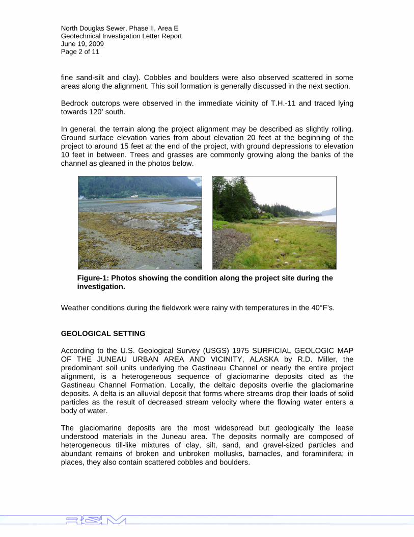
fine sand-silt and clay). Cobbles and boulders were also observed scattered in some areas along the alignment. This soil formation is generally discussed in the next section. Bedrock outcrops were observed in the immediate vicinity of T.H.-11 and traced lying towards 120’ south. In general, the terrain along the project alignment may be described as slightly rolling. Ground surface elevation varies from about elevation 20 feet at the beginning of the project to around 15 feet at the end of the project, with ground depressions to elevation 10 feet in between. Trees and grasses are commonly growing along the banks of the channel as gleaned in the photos below.
Figure-1: Photos showing the condition along the project site during the investigation.
Weather conditions during the fieldwork were rainy with temperatures in the 40°F’s. GEOLOGICAL SETTING According to the U.S. Geological Survey (USGS) 1975 SURFICIAL GEOLOGIC MAP OF THE JUNEAU URBAN AREA AND VICINITY, ALASKA by R.D. Miller, the predominant soil units underlying the Gastineau Channel or nearly the entire project alignment, is a heterogeneous sequence of glaciomarine deposits cited as the Gastineau Channel Formation. Locally, the deltaic deposits overlie the glaciomarine deposits. A delta is an alluvial deposit that forms where streams drop their loads of solid particles as the result of decreased stream velocity where the flowing water enters a body of water. The glaciomarine deposits are the most widespread but geologically the lease understood materials in the Juneau area. The deposits normally are composed of heterogeneous till-like mixtures of clay, silt, sand, and gravel-sized particles and abundant remains of broken and unbroken mollusks, barnacles, and foraminifera; in places, they also contain scattered cobbles and boulders.
North Douglas Sewer, Phase II, Area E Geotechnical Investigation Letter Report June 19, 2009 Page 3 of 11
The glaciomarine diamictons1 are subdivided into four units, of which only three are recognizable mappable materials. The three recognized units are designated as glaciomarine deposits, (first phase); glaciomarine deposits, (second phase); and glaciomarine deposits, (third phase). These deposits are generally described as follows:
Glaciomarine deposits, (first phase) – consists of gray to light gray cohesive generally dense or hard diamictons. They are heterogeneous mixtures of sand, silt, gravel, and clay which contains pebbles, cobbles, and boulders. They also contain broken and whole shells of marine mollusks, some of which are articulated. Glaciomarine deposits, (second phase) – are very hard compact cohesive diamictons that are gray when dry and very dark gray when moist. Texturally, they are heterogeneous and consist dominantly of gravel, with lesser amounts of sand, silt and clay that contain boulders as large as 15 inches in diameter. Fragments of shells are widely scattered through the deposit. Gravel is the principal size of material in the 1 ½-inch or smaller sizes in the glaciomarine deposits, second phase, although the sand content may be nearly as high. Glaciomarine deposits, (third phase) – The third phase of glaciomarine deposits consists of light gray massive compact to punky diamicton; specifically it is a heterogeneous mixture, in order of abundance, of sand, silt, clay, and gravel. Isolated cobbles and boulders are scattered throughout the deposits locally.
Deltaic deposits, those sediments that form a delta, are divided into younger and older delta deposits. Younger delta deposits are those sediments in modern deltas, whereas the older delta deposits are those sediments that formed deltas during the time when the land was still depressed and now may be found several hundreds of feet above modern sea level. The younger delta deposits range from fine to coarse material. Slate, greenstone, and granite are the most common rock types. The younger delta deposits are generally overlain by intertidal silts or fill material. Deltas mapped along Gastineau Channel, Fritz Cove and Mendenhall Lake have a typically triangular or fan shape. SUBSURFACE INVESTIGATION The subsurface investigation was carried-out by drilling, digging, or observing twenty two test hole locations. Two test holes, namely T.H.1 and T.H.2 were drilled at the proximity of the proposed lift station while the twenty other test hole locations were aligned with preliminary manhole locations, which changed in final design. All test holes were drilled except:
• T.H.15 was excavated; and • T.h.11 location served as an observatory point to determine the extent of the
bedrock outcropping at the surface.
1 A diamicton is a poorly sorted or unsorted sediment that consists of particles larger than sand in a matrix of sand, silt, and clay-sized particles.

North Douglas Sewer, Phase II, Area E Geotechnical Investigation Letter Report June 19, 2009 Page 4 of 11
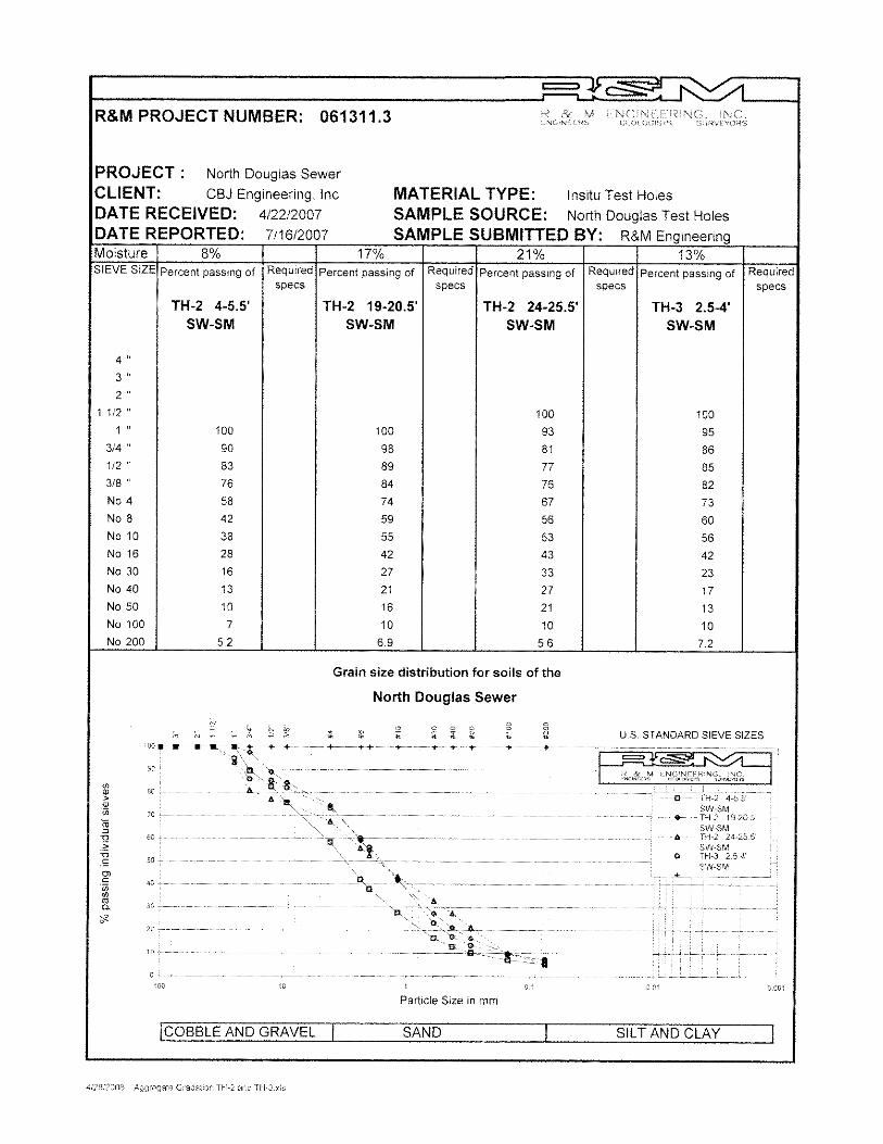
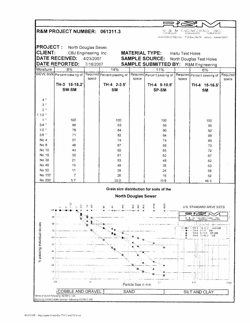
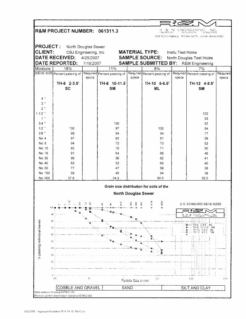
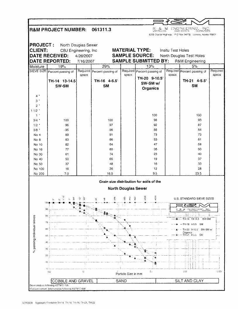
The test holes were terminated after hitting refusal and/or at depths below the planned bottom elevation of the proposed manholes. At the manhole locations, the depths of the boreholes ranged from 5.5 feet to 16.5 feet. In the lift station area, both test holes was drilled down to 25.5 ft., the deepest boreholes. The twenty test holes were drilled with a skid mounted CME-45 drill, while the test pit (T.H.15) was dug with a Hitachi EX80 excavator down to 5.5 feet deep. The test pit was resorted to when the drilling operation was pre-terminated due to thick cobbles and gravel. The location of the test holes and the soil layers encountered is reflected in the attached location map. The ground water level observed in the test holes while drilling is marked as W.D. in the test hole logs. Water depths fluctuate in between boreholes as may be expected due to the influence of tidal action at the time of drilling operation. The water level was encountered as shallow as at ground surface level to a depth of approximately 6.0 ft. RESULTS AND FINDINGS Test hole logs and laboratory test results are presented as attachment with this report. The laboratory soil testing was limited to the evaluation of general index properties. Samples were analyzed for moisture content and grain size distribution. Since sample recovery is generally low, plasticity index test were not carried-out on the plastic fines. For this condition the sample was described and classified by visual-manual procedure (ASTM D 2488). From the foregoing field and laboratory test results, the project site may be generally described to have three (3) distinct subsoil conditions to wit: Loose to Medium dense, gray Gravelly Sand and Sandy Gravel, including sand-sized cemented shale flakes and little cobbles: This is the uppermost soil deposits lying almost entirely at the project site. This layer was found thickest at the proposed Lift Station site where it extended down to 25.5 feet below ground surface. N-values generally ranged from 2 to 15. Tested samples falls under the SW-SM, SP-SM and SM category in the Unified Soil Classification System (USCS). Samples are mostly wet. This layer represents the recent deposits in the area. Dense to very dense, gray to dark gray consisting of a mixture of gravel, sand silt and clay (Glacial Till): This till layer is generally covered by the recent deposits mentioned above. Based on the tested samples, this layer is classified under the SM and ML category in the USCS. Blow counts generally hit refusals (N>60), except in few depths where N-blow counts is 16 to 24 only. Moisture contents ranged from low of 5% to a high of 13%, with mean of 8% indicating that this layer is in dry in-situ condition. Bedrock or Boulders: The bedrock or boulder was presumed hit at the bottom of some of the test holes by the bouncing movement of the sampler driven by the 140-lb hammer, and as noted in the test holes logs. Outcrop of bedrock was observed isolated between the proposed BMH18 and BMH19 (Sta. 74+00 to Sta. 77+00). Thickness was not verified during the investigation.
North Douglas Sewer, Phase II, Area E Geotechnical Investigation Letter Report June 19, 2009 Page 5 of 11
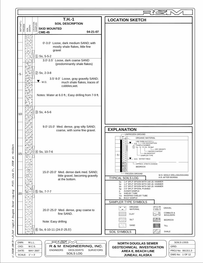
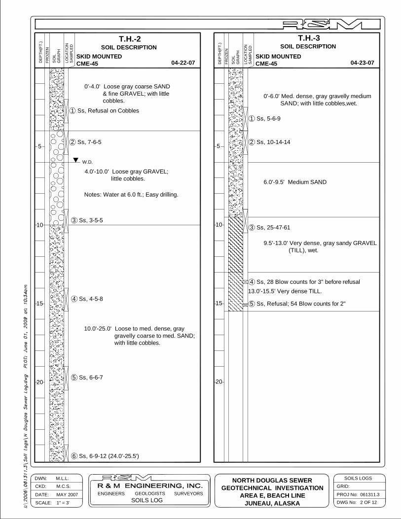
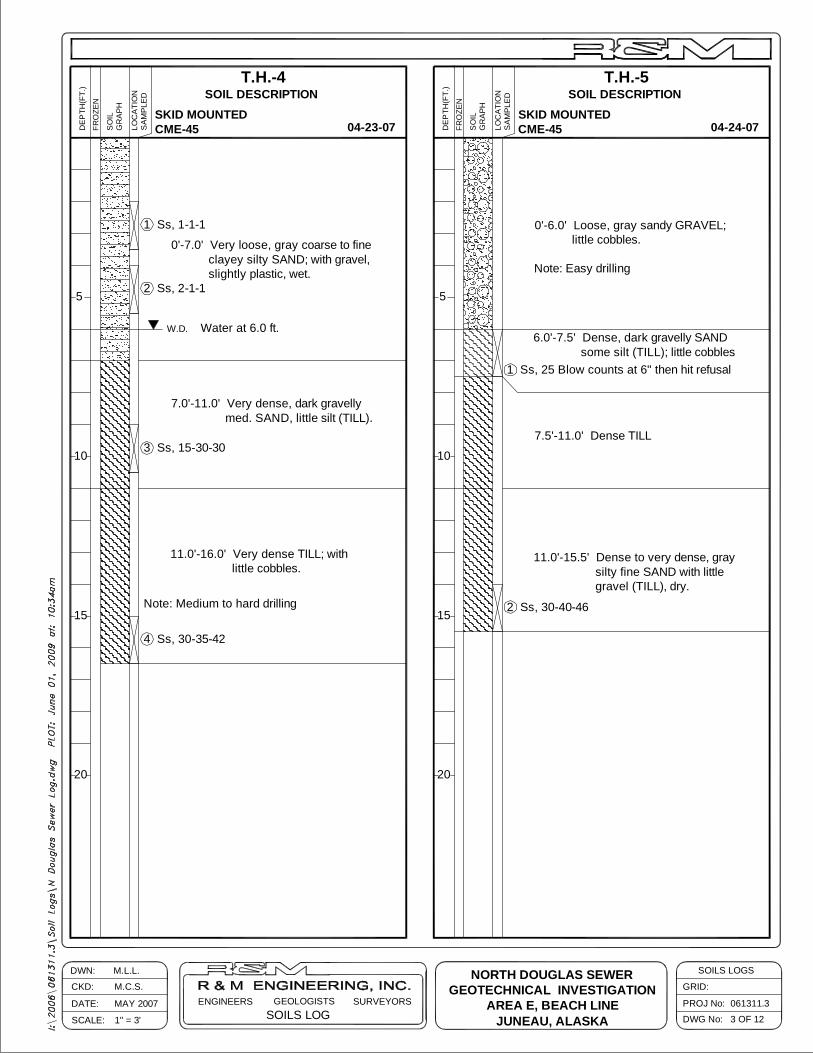
The said distinct subsoil conditions are further discussed in relation to the test holes as follows: Lift Station This site is basically covered by the loose to medium dense, gray gravelly sand and sandy gravel, little cobbles as mentioned above. Sand-sized shale flakes are dominant composition of the sand materials. Two test holes for this site, TH-1 and TH-2, were both drilled to a depth of 25.5 feet below the ground line. The drilling at TH-1 was relatively easy as the drill passed through layers of coarse and medium sand and shale-like material, with some gravel throughout the length of the hole. Some cobbles were encountered from 3.5 feet to 9 feet below the ground line, with a heavier band of cobbles from 7 feet to 9 feet below the ground line. Six samples were obtained at different levels throughout the hole which required an average split spoon sampler blow count of 6 blows per six inches, with a range of 2 to 11 blows per six inches and generally increasing with depth. The laboratory test analysis reflects the silt content (percent passing No. 200 sieve) varying from 3% to 23%, with no correlation to depth. Like TH-1, the drilling at TH-2 was also relatively easy with coarse sand and gravel throughout the length of the hole and a few cobbles. Six samples were obtained at different levels throughout the hole which required an average split spoon sampler blow count of 6 blows per six inches, with a range of 3 to 12 blows per six inches and no correlation to depth. The laboratory test analysis reflects the silt content varying from 5% to 7%, also with no correlation to depth. Pipes and Manholes Generally the manhole locations are covered with loose to med. dense sandy gravel and/or gravelly sand deposits, followed by the underlying dense to very dense glacial till, and lastly by the bedrock. Eleven of the test holes, TH-3, TH-4, TH-5, TH-6, TH-7 TH-9, TH-10, TH-12, TH-13, TH-24, & TH-25, encountered the dense or firm glacial till. Among these holes, TH-7, TH-12, TH-13, & TH-25, were presumed to hit bedrock or boulders at the bottom of the hole. Rock outcrops was observed at the surface of TH-11. The other test holes were generally covered by the uppermost loose to medium dense sands and gravels deposits. Drilling operation through this layer is noted as easy. Test holes had varying depths from 5.5 feet to 16.5 feet below the ground line. About 5.5 feet thick of mostly gravel and cobbles was uncovered in the location of BMH-9. An excavator was use in order to penetrate through the layer as drilling attempts was not successful. The test pit (TH-15) was dug to 5.5 feet below the ground line. The silt content varied from 6% to 62%. A band of siltier material generally existed from 4 feet to 6.5 feet below the ground line throughout the length of the project but was found as shallow as 2 feet and as deep as 16.5 feet below the ground line.
North Douglas Sewer, Phase II, Area E Geotechnical Investigation Letter Report June 19, 2009 Page 6 of 11
CONCLUSIONS AND RECOMMENDATIONS Pipes and Manholes Bearing Capacity and Settlement Based on the test holes logs, the bottom elevation of the lift station and manholes including sewer pipes is to bear either on the medium dense gravelly Sand or on the dense to very dense Till layer. These layers as supported by test results could very well sustain the anticipated light loads of the said proposed structures. Thus, bearing capacity and settlement should not be a problem in the design of the project. Settlement is expected to be purely elastic and the majority is expected to take effect immediately during application of load and during construction. In order to prevent unwarranted settlement, organic matters and pockets of soft clay, or silt that may be observed within the foundation level shall be removed and replaced with select granular fill in compacted lifts. Excavation Supports and Dewatering The high ground water level at the project site would entail dewatering works and the selection of an appropriate trench support for the project. Excavation depth of around 5 feet to over 10 feet below water level is anticipated at different areas. Lowering of the ground water level, or dewatering works, shall be carefully planned by the Contractor. Improperly dewatered trenches in granular soils could result in quick conditions (i.e., effective stress become zero) and a complete loss of shear strength of the soil. In other words, the soil (gravel and sand) becomes unstable and tends to collapse after the water is pumped-out inside the trench if not properly shored. It is also of great importance to prevent the foundation bed from inundation especially if the foundation soil is the dense till. It should be remember that the till layer, even dense in natural state, if become saturated could turn into unmanageable slurry resulting in rapid deterioration in stability. In this condition, the Contractor shall ensure that the water level has brought down to the desired (bottom) level before excavation. Monitoring wells may be established at selected points outside the excavation area to allow confirmation of the water level. In the absence of specific tests and the varying deposition of the soil layers, It may be cited that the precise permeability of the soils at the site is difficult to obtain. Somehow, the published permeability coefficients in several geotechnical engineering books may be assumed to determine the preliminary pumping requirements.
North Douglas Sewer, Phase II, Area E Geotechnical Investigation Letter Report June 19, 2009 Page 7 of 11
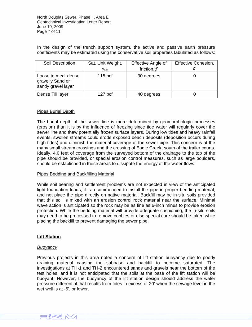
In the design of the trench support system, the active and passive earth pressure coefficients may be estimated using the conservative soil properties tabulated as follows:
Soil Description Sat. Unit Weight, γsat
Effective Angle of friction,φ’
Effective Cohesion, c’
Loose to med. dense gravelly Sand or sandy gravel layer
115 pcf 30 degrees 0
Dense Till layer 127 pcf 40 degrees 0 Pipes Burial Depth The burial depth of the sewer line is more determined by geomorphologic processes (erosion) than it is by the influence of freezing since tide water will regularly cover the sewer line and thaw potentially frozen surface layers. During low tides and heavy rainfall events, swollen streams could erode exposed beach deposits (deposition occurs during high tides) and diminish the material coverage of the sewer pipe. This concern is at the many small stream crossings and the crossing of Eagle Creek, south of the trailer courts. Ideally, 4.0 feet of coverage from the surveyed bottom of the drainage to the top of the pipe should be provided, or special erosion control measures, such as large boulders, should be established in these areas to dissipate the energy of the water flows. Pipes Bedding and Backfilling Material While soil bearing and settlement problems are not expected in view of the anticipated light foundation loads, it is recommended to install the pipe in proper bedding material, and not place the pipe directly on native material. Backfill may be in-situ soils provided that this soil is mixed with an erosion control rock material near the surface. Minimal wave action is anticipated so the rock may be as fine as 6-inch minus to provide erosion protection. While the bedding material will provide adequate cushioning, the in-situ soils may need to be processed to remove cobbles or else special care should be taken while placing the backfill to prevent damaging the sewer pipe. Lift Station Buoyancy Previous projects in this area noted a concern of lift station buoyancy due to poorly draining material causing the subbase and backfill to become saturated. The investigations at TH-1 and TH-2 encountered sands and gravels near the bottom of the test holes, and it is not anticipated that the soils at the base of the lift station will be buoyant. However, the buoyancy of the lift station design should address the water pressure differential that results from tides in excess of 20’ when the sewage level in the wet well is at -5’, or lower.
North Douglas Sewer, Phase II, Area E Geotechnical Investigation Letter Report June 19, 2009 Page 8 of 11
If the final design of the lift station requires excavation to an elevation lower than explored during this investigation, the soils at the bottom of the excavation should be evaluated for soil buoyancy. If poorly draining material is found, it is recommended that engineering solutions addressing soil buoyancy be considered since free drainage of the groundwater may prove difficult. Temporary Shoring Using Steel Sheet Piles Construction of the lift station requires a deep excavation in a tidal area. It has to be reiterated that appropriate excavation supports (sheet piles and struts) and dewatering system is extremely important. Tidal cycles should be noted to determine peak water level while scheduling this work. In addition, some of the manholes and sewer pipe also may require sheet piles, struts and dewatering; where located in the loose sand and gravel material and near the toe of embankment slopes that support improvements above. To support the deep and narrow excavations under water, the use of driven interlocking sheet piles is suggested. Interlocking sheet piles consists of steel pilings that can be reused many times and offer the additional advantage of being watertight. Each individual sheet piling is lowered by crane into a template that holds it in position. Then the piling is driven into place with a pile driver. The stability of the sheet piling is being maintained by means of struts acting as braces to help support the metal sheets. The struts and braces are being installed as excavation proceeds. The adequacy of the piling, bracing, shoring and dewatering is especially important during construction to maintain safety and prevent damage. Failure of a braced wall is normally due to the initial failure of one of the struts, resulting in the progressive failure of the whole system. Piling should be driven to such a depth as may be required to prevent soil boil in the dewatered excavation and provide lateral resistance at the toe of the dewatered excavation. In determining the length of a sheet pile, a 30% increase in the theoretical embedment length is normally to be taken into account for the safety factor. For example and as a guide, in the lift station, the total length of the sheet pile was estimated to be around 29 feet long reckoned from the average ground surface level of TH-1 and TH-2. This was derived from the assumed depth of excavation = 19.5’ + theoretical embedment depth = 7.0’ + 30% of theoretical embedment depth = 2.5’. Selection of the appropriate size (section modulus) of the sheet piles is left to the engineer/designer or contractor, to design for this project. Driving of sheet piles is expected to be generally easy due to the typically loose to medium density of the soil layer. Occasional resistance during driving, however, may occur due to the coarse gravel, or cobbles layer, that could be encountered during driving. Since the sheet piles is to penetrate below the foundation level, pile tips should be located horizontally from the foundation as practical to prevent the soil under the foundation from disturbance during vibration and pull-out of piles. As a guide, the sheet
North Douglas Sewer, Phase II, Area E Geotechnical Investigation Letter Report June 19, 2009 Page 9 of 11
piles should be located at a distant equivalent to the pile tip penetration below the closest foundation edge. It is recommended that piling be extended from the ground surface, or high tide elevation, to prevent the sea water from overflowing into the excavation during high tide and to avoid surface water getting into the excavation during downpour. Some of the advantages of preventing water from flowing into the excavation is to maintain the water inside the excavation at manageable level for quick pumping/dewatering, to have continuous work at all times, and to avoid accumulation of fines (silt and clay soil) carried by surface water during rains. For this condition, the required sheet pile length is longer than the theoretical length mentioned above. After shoring or sheet piling has been completed, removal of soil may proceed by using an excavator capable of reaching the anticipated excavation depth. An excavator with extended boom or mounted with extended stick is suggested. When the excavation reaches the foundation level, care should be taken to avoid over excavation as this may cause further soil disturbance below the foundation level. In this case, a bucket with flat edge may be use for good leveling and avoid over excavation. If over excavation of soil below the foundation level permits, it should be backfilled and compacted to at least equivalent to the in-situ density. Another alternative is a slide rail system that has been used locally on at least four wet well installation in the Juneau area. Dewatering pumps should be installed to maintain the water at manageable level or to maintain below the foundation bed during construction. Sump pits may be design and constructed to collect excess water and pumped out from the excavation. Other Geotechnical Concerns Concrete Foundation For concrete foundation that will be exposed to salt water, it is recommended that concrete mix be design to resist sulfate attack. Trenching and Excavation Generally, excavation through the upper loose to medium dense gray gravelly sand and/or sandy gravel is expected to be easy. On the other hand in areas where dense till or bedrock layer is to be excavated, large excavators, hydraulic breakers, other digging methods; or drilling/blasting may be required. Blasting may be resorted to speed up the excavation. However, the Contractor shall get necessary approval from the CBJ prior to commencing drilling and blasting operation. From the logs, the thickness of hard excavation varies from 3 feet to 10 feet. The areas where it was assessed that large excavators and/or drilling and blasting are anticipated are:

North Douglas Sewer, Phase II, Area E Geotechnical Investigation Letter Report June 19, 2009 Page 10 of 11
1. At the south end of the project between proposed manholes BMH-1 and BMH-3;
2. Possibly to the south of the proposed lift station site in the vicinity of proposed manhole BMH-9; and
3. In the vicinity of proposed manhole BMH-19, where bedrock outcrops was observed.
In general, a trench box will be required throughout the project due to:
• Proximity to property lines; • Proximity to toe of slopes and for retaining structures; • Proximity of the access road; and • Loose soils prone to caving.
Dewatering may be required in some locations due to groundwater and typically for tidal influence. Trench walls will require support prior to dewatering where soils are gravels or sands. Boulders are noted in some of the test holes which would suggest that a larger or wider excavation may be necessary to remove the oversize boulders that obstruct during the excavation. Access Road An access/maintenance road adjacent to the sewer system is recommended for moving equipment along the beach surface. The road should be 12 feet wide, 2.5 feet to 4 feet thick, and comprised of 12-inch minus shot rock. In order to conceal the road, it is recommended to construct it 4 inches to 6 inches below the natural ground line and replace the native surface material to match the existing adjacent beach slope. The contractor may elect to use a fabric layer to minimize the rock depth. Liquefaction Considerations Liquefaction is the tendency of some soil (especially non-plastic fine to medium sand) to compact due to cyclic stresses (earthquake). The tendency of soil to compact (decrease in volume) will lead to the increase in porewater pressure causing transient loss in shear strength as well as bearing capacity. The possibility that an earthquake may occur in a given area at the present state-of-the art, is essentially a probabilistic exercise based upon the past earthquake history of the area. Since it is accepted with some certainty that there is an earthquake risk in the Juneau area, the susceptibility of some loose cohesionless fine-grained soil to potential disturbance from earthquake induced shear stress must be evaluated. In our project site, although liquefaction is not totally disregarded, the presence of coarse gravel and cobbles and the insignificant thickness (generally less than 10 feet) of the loose layer, it may be concluded that liquefaction, if any, may be generally non-destructive.
North Douglas Sewer, Phase II, Area E Geotechnical Investigation Letter Report June 19, 2009 Page 11 of 11
At present there is no known liquefaction related damaged reported in Juneau, Alaska. LIMITATIONS This report has been prepared to aid in the design of this proposed sewer system. Its scope is limited to the project and location described herein and represents our understanding of the soil/rock conditions at the site, at the time of the investigation. Should there be appreciable differences found in the soil/rock conditions during the construction phase, or should there be any differences in our understanding of the project requirements, we should be immediately notified so that supplemental recommendations can be provided. Should these recommendations be utilized for design efforts, we request the opportunity to review the design for conformance to our recommendations. If you have any questions or concerns, please feel free to contact our office at (907) 780-6060. If you would like additional copies of this report, do not hesitate to contact us. Sincerely, R&M ENGINEERING, INC. Edmon SB. Cruz Michael C. Story, P.E. Engineering Geologist Civil Engineer Attachments: Geotechnical Investigation Location Map
Soil Logs Laboratory Test Data Sheets Cc: Donald Beard, P.E., Tetra Tech I:\2006\061311.3\Geotech Report\090619, Area E Geotech Report.doc
LOCATION SKETCH
FROZEN GROUND
APPROX. STRATA CHANGE
UNFROZEN GROUND
SAMPLE NUMBERSs, 72, 57.1%, 85.9pcf
BEDROCK
Little Visible Ice 0-10 V
ORGANIC MATERIAL
MODIFIED SHELBY TUBE
AUGER SAMPLE2.5" SPLIT SPOON, PUSHED2.5" SPLIT SPOON WITH 340 LB. HAMMER1.4" SPLIT SPOON WITH 340 LB. HAMMER1.4" SPLIT SPOON WITH 140 LB. HAMMER
MATERIALORGANIC
SAMPLER TYPE SYMBOLS
TYPICAL SOILS LOG
A
SCALE:
DATE:
CKD:
DWN:
SURVEYORSENGINEERS GEOLOGISTSSOILS LOG
SOIL SYMBOLS
SAND
SILT
CLAY
BULK SAMPLE
SHELBY TUBE
BsTmTs
10
1
SpShSzSs
W.D.
5
EXPLANATION
A.B.
5
LOC
ATI
ON
SA
MP
LED
DEP
TH(F
T.)
FRO
ZEN
SO
ILG
RA
PH
04-21-07
T.H.-1SOIL DESCRIPTION
1 OF 12
061311.3
SOILS LOGS
DWG No:
PROJ No:
GRID:
COBBLES &BOULDERS
BEDROCK
GRAVEL
W.D.-WHILE DRILLING/DIGGINGA.B.-AFTER BORING
WATER CONTENTDRY DENSITY
WATER TABLE
SAMPLER TYPEBLOWS/FOOT
ICE DESCRIPTIONx
20
15
1" = 3'
M.L.L.
M.C.S.
MAY 2007
2 Ss, 2-3-8
1 Ss, 5-5-2
3 Ss, 4-5-6
4 Ss, 10-7-6
5 Ss, 7-7-7
6 Ss, 6-10-11 (24.0'-25.5')
W.D.3.5'-9.0' Loose, gray gravelly SAND; much shale flakes, traces of cobbles,wet.
3.0'-3.5' Loose, dark coarse SAND (predominantly shale flakes)
0'-3.0' Loose, dark medium SAND; with mostly shale flakes, little fine gravel
9.0'-15.0' Med. dense, gray silty SAND; coarse, with some fine gravel.
15.0'-20.0' Med. dense dark med. SAND; little gravel, becoming gravelly at the bottom.
20.0'-25.0' Med. dense, gray coarse to fine SAND.
TILL
SHALE
"E"-SKID MOUNTEDCME-45
NORTH DOUGLAS SEWERGEOTECHNICAL INVESTIGATION
AREA E, BEACH LINEJUNEAU, ALASKA
Notes: Water at 6.0 ft.; Easy drilling from 7-9 ft.
Note: Easy drilling
10
1" = 3'SCALE:
M.L.L.DWN:
MAY 2007
M.C.S.CKD:
DATE:
20
15
PROJ No:
DWG No:
SOILS LOGS
SOILS LOGGEOLOGISTSENGINEERS SURVEYORS
GRID:
2 OF 12
061311.3
5
GR
AP
HS
OIL
FRO
ZEN
DEP
TH(F
T.)
SA
MP
LED
LOC
ATI
ON SOIL DESCRIPTION
T.H.-2
04-22-07
20
15
10
5
SA
MP
LED
LOC
ATI
ON
GR
AP
HS
OIL
FRO
ZEN
DEP
TH(F
T.)
3 Ss, 3-5-5
1 Ss, Refusal on Cobbles
W.D.
2 Ss, 7-6-5
4 Ss, 4-5-8
T.H.-3SOIL DESCRIPTION
04-23-07
0'-4.0' Loose gray coarse SAND & fine GRAVEL; with little cobbles.
10.0'-25.0' Loose to med. dense, gray gravelly coarse to med. SAND; with little cobbles.
4.0'-10.0' Loose gray GRAVEL; little cobbles.
5 Ss, 6-6-7
6 Ss, 6-9-12 (24.0'-25.5')
0'-6.0' Med. dense, gray gravelly medium SAND; with little cobbles,wet.
6.0'-9.5' Medium SAND
9.5'-13.0' Very dense, gray sandy GRAVEL (TILL), wet.
13.0'-15.5' Very dense TILL.
1 Ss, 5-6-9
2 Ss, 10-14-14
3 Ss, 25-47-61
4 Ss, 28 Blow counts for 3" before refusal
5 Ss, Refusal; 54 Blow counts for 2"
-LINESKID MOUNTEDCME-45
SKID MOUNTEDCME-45
NORTH DOUGLAS SEWERGEOTECHNICAL INVESTIGATION
AREA E, BEACH LINEJUNEAU, ALASKA
Notes: Water at 6.0 ft.; Easy drilling.
DATE: MAY 2007
SCALE: 1" = 3'
CKD: M.C.S.
DWN: M.L.L.
ENGINEERS GEOLOGISTSSOILS LOG
SURVEYORS
3 OF 12
061311.3PROJ No:
DWG No:
GRID:
SOILS LOGS
T.H.-5SOIL DESCRIPTION
DEP
TH(F
T.)
FRO
ZEN
SO
ILG
RA
PH
LOC
ATI
ON
SA
MP
LED
15
10
5
04-24-07
20
W.D.
T.H.-4
10
5
SA
MP
LED
LOC
ATI
ON
GR
AP
HS
OIL
FRO
ZEN
DEP
TH(F
T.)
SOIL DESCRIPTION
04-23-07
20
15
0'-7.0' Very loose, gray coarse to fine clayey silty SAND; with gravel, slightly plastic, wet.
7.0'-11.0' Very dense, dark gravelly med. SAND, little silt (TILL).
11.0'-16.0' Very dense TILL; with little cobbles.
0'-6.0' Loose, gray sandy GRAVEL; little cobbles.
Note: Easy drilling
6.0'-7.5' Dense, dark gravelly SAND some silt (TILL); little cobbles
7.5'-11.0' Dense TILL
11.0'-15.5' Dense to very dense, gray silty fine SAND with little gravel (TILL), dry.
1 Ss, 1-1-1
2 Ss, 2-1-1
3 Ss, 15-30-30
4 Ss, 30-35-42
1 Ss, 25 Blow counts at 6" then hit refusal
2 Ss, 30-40-46
ESKID MOUNTEDCME-45
SKID MOUNTEDCME-45
NORTH DOUGLAS SEWERGEOTECHNICAL INVESTIGATION
AREA E, BEACH LINEJUNEAU, ALASKA
Water at 6.0 ft.
Note: Medium to hard drilling

SOILS LOGGEOLOGISTSDATE: MAY 2007 ENGINEERS
SCALE: 1" = 3'
DWN: M.L.L.
CKD: M.C.S.SURVEYORS PROJ No: 061311.3
DWG No: 4 OF 12
GRID:
SOILS LOGS
20 20
15 15
T.H.-6
10
5
10
5
SOIL DESCRIPTIOND
EPTH
(FT.
)
FRO
ZEN
SO
ILG
RA
PH
LOC
ATI
ON
SA
MP
LED
04-24-07 SA
MP
LED
LOC
ATI
ON
GR
AP
HS
OIL
FRO
ZEN
DEP
TH(F
T.)
0'-3.5' Loose silty GRAVEL.
Easy Drilling
3.5'-10.0' Dense to very dense silty med. SAND with little gravel (TILL); trace of cobbles
1 Ss, 15-18-12
2 Ss, 20-30-24
T.H.-7SOIL DESCRIPTION
04-24-07
0'-3.0' Coarse to med. SAND; with little gravel.
3.0'-7.0' Dense to med. dense, gray med. to fine SAND; with coarse to fine gravel.Note: Water at 4.0 ft.
1 Ss, 13-16-24
2 Ss, 5-8-16
7.0'-9.0' Loose TILL; with gravel
9.0'-12.0' Very stiff, gray sandy SILT (TILL); med. plastic.
SKID MOUNTEDCME-45
SKID MOUNTEDCME-45
NORTH DOUGLAS SEWERGEOTECHNICAL INVESTIGATION
AREA E, BEACH LINEJUNEAU, ALASKA
Refusal at 12.0 ft.; Split-spoon samplerbounced
W.D.

SOILS LOGGEOLOGISTSDATE: MAY 2007 ENGINEERS
SCALE: 1" = 3'
DWN: M.L.L.
CKD: M.C.S.SURVEYORS PROJ No: 061311.3
DWG No: 5 OF 12
GRID:
SOILS LOGS
20 20
15 15
T.H.-8
10
5
10
5
SOIL DESCRIPTIOND
EPTH
(FT.
)
FRO
ZEN
SO
ILG
RA
PH
LOC
ATI
ON
SA
MP
LED
04-25-07 SA
MP
LED
LOC
ATI
ON
GR
AP
HS
OIL
FRO
ZEN
DEP
TH(F
T.)
0'-3.5' Loose, gray clayey fine SAND; medium plastic.
3.5'-10.5' Med. dense, fine SAND & SILT; with trace of fine gravel
Note: Easy drilling
1 Ss, 1-2-1
2 Ss, 5-9-10
T.H.-9SOIL DESCRIPTION
04-25-07
0'-4.0' Loose, gray clayey med. SAND; slight to med. plastic, little gravel, wet.
4.0'-9.5' Stiff to very stiff, dark sandy SILT with little gravel (TILL); dry. slighly plastic when wet
1 Ss, 1-3-2
2 Ss, 8-7-9
10.5'-11.5' Med. dense, dark silty SAND; mostly shale flakes, some fine gravel.
Note: Easy drilling
3 Ss, 20-20-8
W.D.
SKID MOUNTEDCME-45
SKID MOUNTEDCME-45
NORTH DOUGLAS SEWERGEOTECHNICAL INVESTIGATION
AREA E, BEACH LINEJUNEAU, ALASKA
SOILS LOGGEOLOGISTSDATE: MAY 2007 ENGINEERS
SCALE: 1" = 3'
DWN: M.L.L.
CKD: M.C.S.SURVEYORS PROJ No: 061311.3
DWG No: 6 OF 12
GRID:
SOILS LOGS
20 20
15 15
T.H.-10
10
5
10
5
SOIL DESCRIPTIOND
EPTH
(FT.
)
FRO
ZEN
SO
ILG
RA
PH
LOC
ATI
ON
SA
MP
LED
04-25-07 SA
MP
LED
LOC
ATI
ON
GR
AP
HS
OIL
FRO
ZEN
DEP
TH(F
T.)
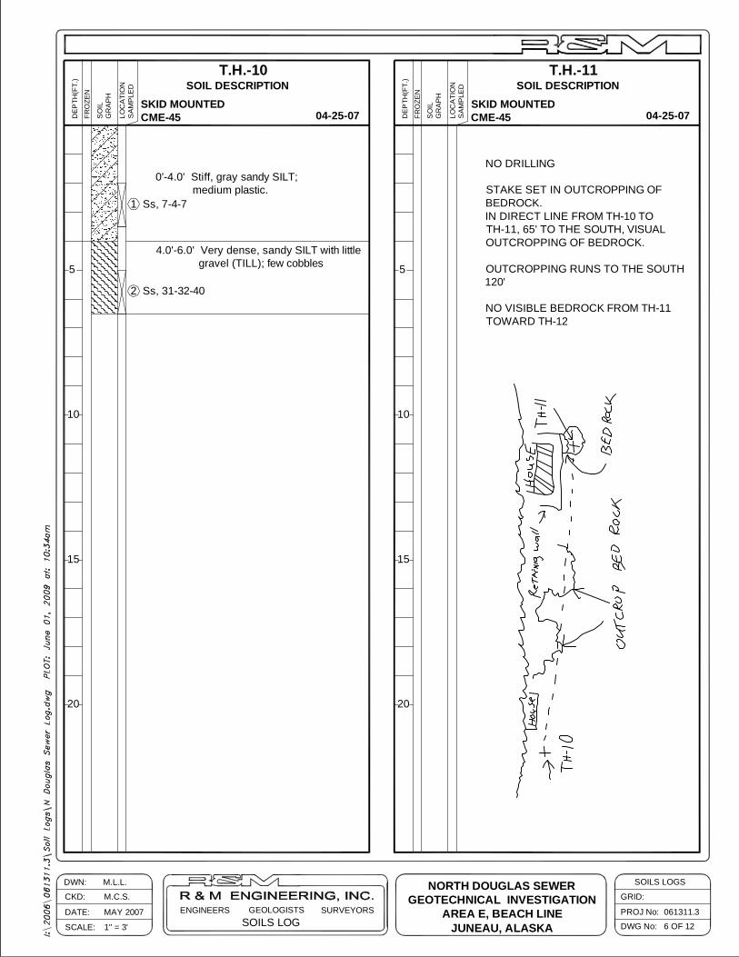
0'-4.0' Stiff, gray sandy SILT; medium plastic.
4.0'-6.0' Very dense, sandy SILT with little gravel (TILL); few cobbles
1 Ss, 7-4-7
2 Ss, 31-32-40
T.H.-11SOIL DESCRIPTION
04-25-07
NO DRILLING
STAKE SET IN OUTCROPPING OFBEDROCK.IN DIRECT LINE FROM TH-10 TOTH-11, 65' TO THE SOUTH, VISUALOUTCROPPING OF BEDROCK.
OUTCROPPING RUNS TO THE SOUTH120'
NO VISIBLE BEDROCK FROM TH-11TOWARD TH-12
SKID MOUNTEDCME-45
SKID MOUNTEDCME-45
NORTH DOUGLAS SEWERGEOTECHNICAL INVESTIGATION
AREA E, BEACH LINEJUNEAU, ALASKA
SOILS LOGGEOLOGISTSDATE: MAY 2007 ENGINEERS
SCALE: 1" = 3'
DWN: M.L.L.
CKD: M.C.S.SURVEYORS PROJ No: 061311.3
DWG No: 7 OF 12
GRID:
SOILS LOGS
20 20
15 15
T.H.-12
10
5
10
5
SOIL DESCRIPTIOND
EPTH
(FT.
)
FRO
ZEN
SO
ILG
RA
PH
LOC
ATI
ON
SA
MP
LED
04-25-07 SA
MP
LED
LOC
ATI
ON
GR
AP
HS
OIL
FRO
ZEN
DEP
TH(F
T.)
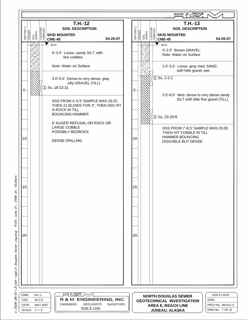
0'-3.0' Loose, sandy SILT; with few cobbles.
Note: Water on Surface
3.0'-5.0' Dense to very dense, gray silty GRAVEL (TILL).
1 Ss, 18-22-21
T.H.-13SOIL DESCRIPTION
04-26-07
SSS FROM 4'-5.5' SAMPLE WAS 18-22,THEN 21 BLOWS FOR 3", THEN SSS HITA ROCK IN TILLBOUNCING HAMMER
6' AUGER REFUSAL ON ROCK ORLARGE COBBLEPOSSIBLY BEDROCK
DENSE DRILLING
0'-2.0' Brown GRAVEL.Note: Water on Surface
2.0'-3.5' Loose, gray med. SAND; with little gravel, wet.
1 Ss, 2-2-2
2 Ss, 23-29-R
3.5'-8.0' Med. dense to very dense sandy SILT with little fine gravel (TILL).
SKID MOUNTEDCME-45
SKID MOUNTEDCME-45
NORTH DOUGLAS SEWERGEOTECHNICAL INVESTIGATION
AREA E, BEACH LINEJUNEAU, ALASKA
W.D. W.D.
SSS FROM 7'-8.5' SAMPLE WAS 23-29,THEN HIT COBBLE IN TILLHAMMER BOUNCINGDIGGABLE BUT DENSE

SOILS LOGGEOLOGISTSDATE: MAY 2007 ENGINEERS
SCALE: 1" = 3'
DWN: M.L.L.
CKD: M.C.S.SURVEYORS PROJ No: 061311.3
DWG No: 8 OF 12
GRID:
SOILS LOGS
20 20
15 15
T.H.-14
10
5
10
5
SOIL DESCRIPTIOND
EPTH
(FT.
)
FRO
ZEN
SO
ILG
RA
PH
LOC
ATI
ON
SA
MP
LED
04-26-07 SA
MP
LED
LOC
ATI
ON
GR
AP
HS
OIL
FRO
ZEN
DEP
TH(F
T.)
0'-6.0' Loose to med. dense, gray sandy GRAVEL; some cobbles, much shale flakes, wet.
6.0'-13.0' Med. dense, medium SAND; little gravel, trace of silt.
Note: Easy drilling
1 Ss, 15-18-11
T.H.-15SOIL DESCRIPTION
04-26-07
0'-5.5' GRAVEL AND COBBLES
2 Ss, 6-7-7
4 DRILLING ATTEMPTS TO GET AUGERTHROUGH 1'-COBBLES, VERY DIGGABLE
TEST PIT DOWN TO 5.5' GRAVEL ANDCOBBLES ALL THE WAY, THEN HITBEDROCK OR 5' BOULDERSCRAPED ALONG IT FOR 5'APPEARS TO BE BEDROCK
SKID MOUNTEDCME-45
HITACHI EX-80EXCAVATOR - TEST PIT
NORTH DOUGLAS SEWERGEOTECHNICAL INVESTIGATION
AREA E, BEACH LINEJUNEAU, ALASKA
W.D.
BEDROCK 5.5' ?
SOILS LOGGEOLOGISTSDATE: MAY 2007 ENGINEERS
SCALE: 1" = 3'
DWN: M.L.L.
CKD: M.C.S.SURVEYORS PROJ No: 061311.3
DWG No: 9 OF 12
GRID:
SOILS LOGS
20
15
10
5
SA
MP
LED
LOC
ATI
ON
GR
AP
HS
OIL
FRO
ZEN
DEP
TH(F
T.)
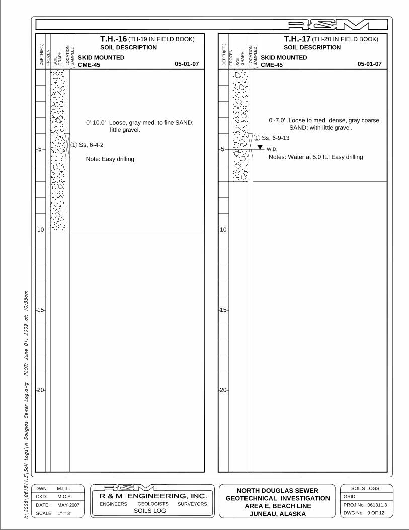
T.H.-16SOIL DESCRIPTION
05-01-07
0'-10.0' Loose, gray med. to fine SAND; little gravel.
Note: Easy drilling
1 Ss, 6-4-2
20
15
T.H.-17
10
5
SOIL DESCRIPTION
DEP
TH(F
T.)
FRO
ZEN
SO
ILG
RA
PH
LOC
ATI
ON
SA
MP
LED
05-01-07
0'-7.0' Loose to med. dense, gray coarse SAND; with little gravel.
Notes: Water at 5.0 ft.; Easy drilling
1 Ss, 6-9-13
SKID MOUNTEDCME-45
SKID MOUNTEDCME-45
NORTH DOUGLAS SEWERGEOTECHNICAL INVESTIGATION
AREA E, BEACH LINEJUNEAU, ALASKA
W.D.
(TH-19 IN FIELD BOOK) (TH-20 IN FIELD BOOK)
SOILS LOGGEOLOGISTSDATE: MAY 2007 ENGINEERS
SCALE: 1" = 3'
DWN: M.L.L.
CKD: M.C.S.SURVEYORS PROJ No: 061311.3
DWG No: 10 OF 12
GRID:
SOILS LOGS
20
15
10
5
SA
MP
LED
LOC
ATI
ON
GR
AP
HS
OIL
FRO
ZEN
DEP
TH(F
T.)
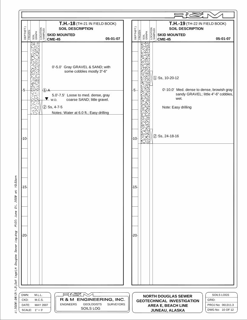
T.H.-18SOIL DESCRIPTION
05-01-07
0'-5.0' Gray GRAVEL & SAND; with some cobbles mostly 3"-6"
2 Ss, 4-7-5
5.0'-7.5' Loose to med. dense, gray coarse SAND; little gravel.
Notes: Water at 6.0 ft.; Easy drilling
1 A
20
15
T.H.-19
10
5
SOIL DESCRIPTION
DEP
TH(F
T.)
FRO
ZEN
SO
ILG
RA
PH
LOC
ATI
ON
SA
MP
LED
05-01-07
0'-10.0' Med. dense to dense, browish gray sandy GRAVEL; little 4"-6" cobbles, wet.
Note: Easy drilling
1 Ss, 10-20-12
2 Ss, 24-18-16
SKID MOUNTEDCME-45
SKID MOUNTEDCME-45
NORTH DOUGLAS SEWERGEOTECHNICAL INVESTIGATION
AREA E, BEACH LINEJUNEAU, ALASKA
W.D.
(TH-21 IN FIELD BOOK) (TH-22 IN FIELD BOOK)
SOILS LOGGEOLOGISTSDATE: MAY 2007 ENGINEERS
SCALE: 1" = 3'
DWN: M.L.L.
CKD: M.C.S.SURVEYORS PROJ No: 061311.3
DWG No: 11 OF 12
GRID:
SOILS LOGS
20
15
10
5
SA
MP
LED
LOC
ATI
ON
GR
AP
HS
OIL
FRO
ZEN
DEP
TH(F
T.)
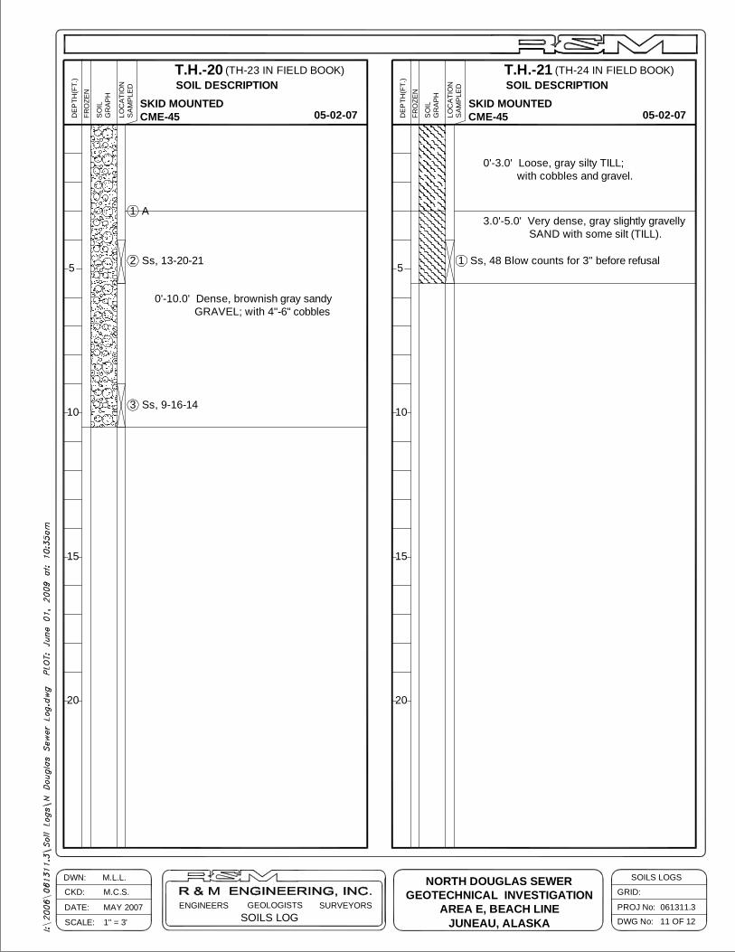
T.H.-20SOIL DESCRIPTION
05-02-07
0'-10.0' Dense, brownish gray sandy GRAVEL; with 4"-6" cobbles
2 Ss, 13-20-21
3 Ss, 9-16-14
20
15
T.H.-21
10
5
SOIL DESCRIPTION
DEP
TH(F
T.)
FRO
ZEN
SO
ILG
RA
PH
LOC
ATI
ON
SA
MP
LED
05-02-07
0'-3.0' Loose, gray silty TILL; with cobbles and gravel.
3.0'-5.0' Very dense, gray slightly gravelly SAND with some silt (TILL).
SKID MOUNTEDCME-45
SKID MOUNTEDCME-45
NORTH DOUGLAS SEWERGEOTECHNICAL INVESTIGATION
AREA E, BEACH LINEJUNEAU, ALASKA
1 Ss, 48 Blow counts for 3" before refusal
1 A
(TH-24 IN FIELD BOOK)(TH-23 IN FIELD BOOK)
SOILS LOGGEOLOGISTSDATE: MAY 2007 ENGINEERS
SCALE: 1" = 3'
DWN: M.L.L.
CKD: M.C.S.SURVEYORS PROJ No: 061311.3
DWG No: 12 OF 12
GRID:
SOILS LOGS
20
15
10
5
SA
MP
LED
LOC
ATI
ON
GR
AP
HS
OIL
FRO
ZEN
DEP
TH(F
T.)
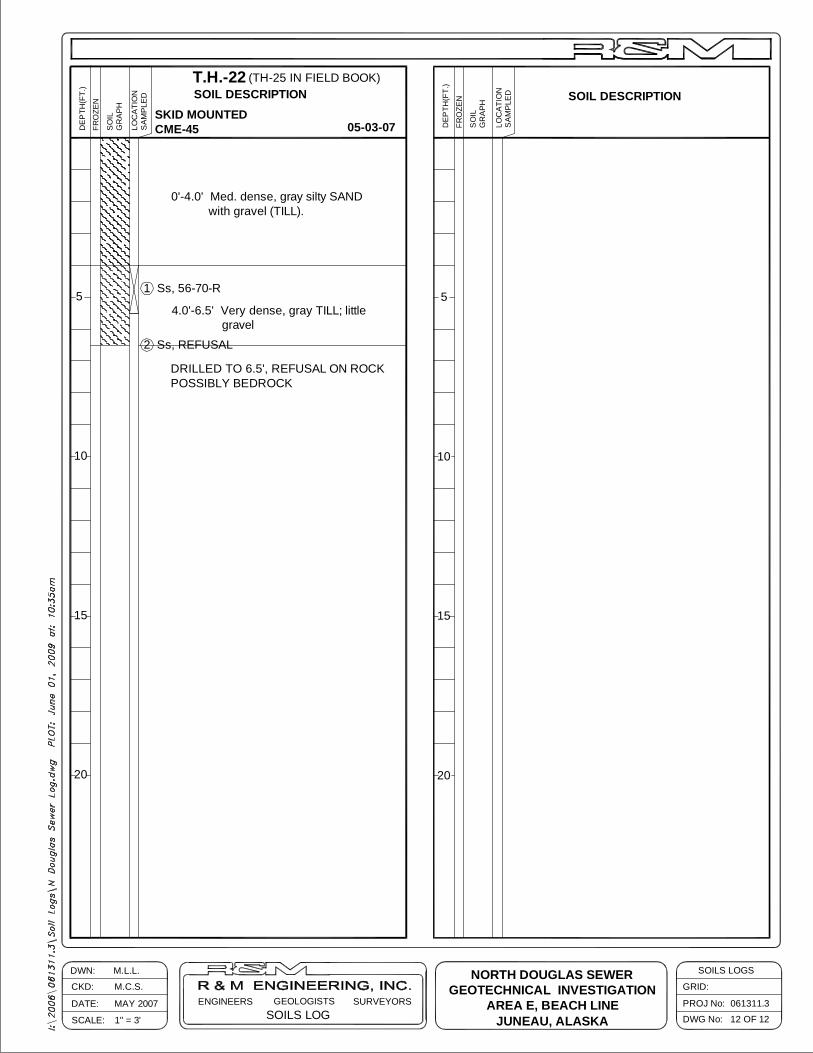
T.H.-22SOIL DESCRIPTION
05-03-07
0'-4.0' Med. dense, gray silty SAND with gravel (TILL).
1 Ss, 56-70-R
4.0'-6.5' Very dense, gray TILL; little gravel
2 Ss, REFUSAL
SKID MOUNTEDCME-45
NORTH DOUGLAS SEWERGEOTECHNICAL INVESTIGATION
AREA E, BEACH LINEJUNEAU, ALASKA
DRILLED TO 6.5', REFUSAL ON ROCKPOSSIBLY BEDROCK
10
20
15
5
GR
AP
HS
OIL
FRO
ZEN
DEP
TH(F
T.)
SA
MP
LED
LOC
ATI
ON SOIL DESCRIPTION
(TH-25 IN FIELD BOOK)