rmis view/print document cover sheet - digital library/67531/metadc682477/m2/1/high... ·...
TRANSCRIPT

"" RMIS View/Print Document Cover Sheet""
This document was retrieved from the Documentation and Records Manaqement (DRM) ISEARCH System. It is intended for Information only and may not be the most recent or updated version. Contact a Document Sewice Center (see Hanford Info for locations) if you need add it i o n al retrieval i n fo r m at i o n .
Accession #: D296005612
Document #: SD-CP-TI-196
TitlelDesc: I T 1 994 & I T 1 995 THERMAL STABILIZATION CAMPAIGN REPORT
Pages: 29

Page 1 of 1_
1 EDT 139863 JAN 12$96@ 2 To (Receiving Organlzat~onl 3 From (Originating Organization) 4 Related EDT No
ENGINE ERl NG DATA TRANSMllTAL
15.536 * 7 Purchaseorder No:
1 1 Receiver Remarks:
1.2,3. or4ree MRP 5.43 and EP-1 7
21. DOE APPROVAL(if required)
i#? Autfk%&atme 0 Approved wlcomments
18. 19 20. - Ltr No.
for Receiving Organization Engineer’s Manager 0 Disapproved wlcommentr
ED-7400-172 (2/89)

WHC-SO-CP-TI-196, Rev. 0
FY94195 Thermal Stabilization Campaign Report
W.S. Lewis WHC, Richland, WA 99352 U.S. Department o f Energy Contract DE-AC06-87RL10930
EDT/ECN: 129862 UC: UC-500 Org Code: 15530 Charge Code: k6133 B&R Code: EW7003000 Tota l Pages: 26
Key Words: HC-21C, Furnaces, Pu Bearing Mater ia l , Thermal S t a b i l i z a t i o n , Sludge S t a b i l i z a t i o n , Campaign Report
Abstract: S t a b i l i z a t i o n Campaign.
The r e p o r t prov ides a synopsis o f t he FY94/95 Thermal
TRADEHARK DISCLAIMER. R e f e r e e herein t o any speci f ic c n r r r c i a l product, process, or service by trade nan%, trademark, manufacturer, or otheruise, dots rVlt necessarily const i tute o r inp ly i t s endorsement, reconnmdation, or favoring by the United States Govermnt o r any agemy thereof or i t s cmtractors or stbcontracfors.
Printed in the United States of America. Docunent Control Services, P.O. Box 1970, Yai lstop H6-OB. Richlend UA W352, Phon (509) 372-2420; Fax ( 5 0 9 ) 376-4989. i
To obtain copies o f t h i s dosunent. contact: UHClBCS
Approved for Public Release
A-6600-073 (10195) GEF321

n I FY94/95 THERMAL STABILIZATION WHC-SD-CP-TI-196 CAMPAIGN REPORT I REV-0
TABLE OF CONTENTS
1. SUMMARY
2. INTRODUCTION
3. DISCUSSION 3.1. Process Descr io t ion 3.2. Svstem Analvs i s
3.2.1. Performance 3.2.2. Downtime Analvsis 3.2.3. Problems and Downtime Items
3.2.3.1. O f f Gas System 3.2.3.2. Boat M a t e r i a l
3.2.4. Off-Standard Condit ions 3.3. Product O u a l i t r 3.4. Radiat ion EXD osure Anal v s i s
4. RECOMMENDATIONS 4.1. Maintenance items 4.2. Ooerational o r Programmatic Changes 4.4. 94-1 Furnace I n s t a l l a t i o n
5. GLOSSARY
6. REFERENCES
LIST OF FIGURES
Figure 1 Thermal S t a b i l i z a t i o n Operating E f f i c i e n c y Figure 2 Thermal S t a b i l i z a t i o n Recycle Figure 3 Thermal S t a b i l i z a t i o n Ranked Downtime Items Figure 4 O f f Gas L ine Temperature P r o f i l e Furnace 1 Figure 5 O f f Gas L ine Temperature P r o f i l e Furnace 2 F igure 6 Boat Mater ia l Corrosion Test ing F igure 7 Simulated TGA Figure 8 Boat Temperature P r o f i l e Figure 9 Simulated TGA f o r Extended 1OOO'C Soak Figure 10 Thermal S t a b i l i z a t i o n Exposure
3
3
4 4 4 4 8
10 10 13 15 15 20
22 22 22 24
25
26
6 7 9
11 12 14 17 18 19 21
LIST OF TABLES
Table 1 System Performance Overview Table 2 Table 3 Thermal S t a b i l i z a t i o n Downtime Items Table 4 Unusual Occurrence Reports Table 5 O f f Normals
Deta i led Feed Input For the FY94 Campaign 4 5 8
15 15


CAMPAIGN REPORT
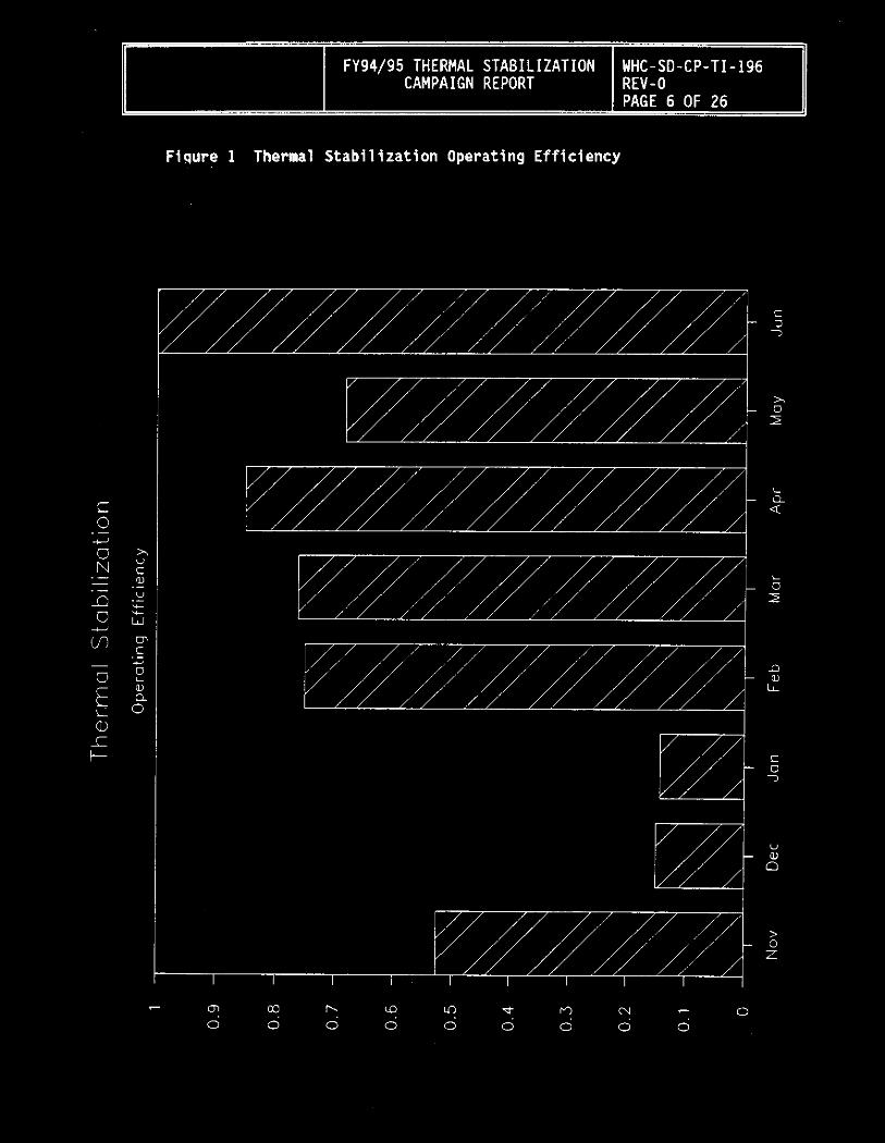
The Operating Efficiency for the FY94 campaign was generated as a baseline for future campaigns. The monthly progressions of the operating efficiency is shown in Figure 1. reflected in the operating efficiency, an important indicator of performance is the number of product cans that require recycle. Figure 2 shows the percent of product cans that required reprocessing per month of operation. The large number of cans requiring reprocessing towards the end of the campaign is directly related to the change of performing LO1 analysis at IOOO'C rather than 450'C. The reasons for this are discussed in section 3.3 .
A total o f 236 items were stabilized during the campaign. These items are detailed in tabje 2. on the blend plan, 23 items had to be replaced with other material because they did not meet the feed criteria in OSD-Z- 184-00006. These items that were not processed included Plutonium Fluoride and partially burned polycubes. The replacement items were obtained from material that had been taken out of processing gloveboxes during on going remediation activities and items that had originally been left off the blend plan because they were listed as plutonium metal turnings. Upon inspection of these items it was determined that all of the metal had oxidized and therefore they would meet the feed specifications.
Although not
Of the original 236 items
Table 2 Detailed Feed Input For the FY94 Campaign
Feed Tvoe
Oxide
PRF Sludge
Oxalate
Total
# o f Items K ~ s Pu % (Pul of total
51 4.0 18%
144
41
236
11.5 52%
6.5 3 0%
22 100%
FY 94/95 THERMAL STAB1 L I Z A T I O N CAMPAIGN REPORT
Fiqure 1 Thermal Stabilization Operating Efficiency
WHC- S O - C P - T I - 196 REV-0 PAGE 6 OF 26
C 3 3
x 0 I
i Q 4
L 0 I
n a,
LL
C 0 7
v a, a
> 0 z
ul 7 0 0 0
c a) r. W 0 0 0
d r, 0.
0 0 0

FY 94/95 THERMAL STAB I L I Z A T ION WHC - SD- C P- T I - 196 CAMPAIGN REPORT R E V - 0
PAGE 7 OF 26
Figure 2 Thermal Stabilization Recycle
c 0
- U E
a,
x a, w rn C
3 U G) LY v) C 0 0
R
- U
U
._ L ._
t-
0 0
0 0 0' 0 cn m b iL7
0 0 0 0 In d M N
0 0 ?

FY94/95 THERMAL STABILIZATION WHC-SD-CP-TI-196 CAMPAIGN REPORT REV-0
PAGF 8 OF 76
3.2.2. Downtime Analvs is
The sludge s t a b i l i z a t i o n downtime was measured i n l o s t charges. Table 3 and F igure 3 ranks the downtime items along w i t h the associated l o s t charges and percent o f t o t a l downtime.
The seismic over pack i nc iden t resu l ted i n the s ing le l a r g e s t downtime i tem (44%). This i tem was due t o problems i n conduct o f operations r a t h e r than actual processing problems. By f a r t he l a r g e s t source o f downtime r e l a t e d t o the process was d i f f i c u l t i e s i n the o f f gas system. Problems w i t h the o f f gas system accounted f o r 29% o f t h e downtime. system problems were solved, downtime from the process was v i r t u a l l y e l iminated. The o f f gas system problems are f u r t h e r discussed i n sec t ion 3.2.3.1. r e l a t e d t o Thermal S t a b i l i z a t i o n ) accounted f o r roughly 27% o f t he downtime. p l a n t downtime. expected t o be low.
Once the o f f gas
Downtime from t h e p l a n t (not
Future operations can probably expect s i m i l a r Downtime due t o processing problems can be
Table 3 Thermal S t a b i l i z a t i o n Downtime Items
FREQUENCY LOST % DT CHARGES
COP - Seismic Over Pack Event 1 MEC - Plugged F i l t e r s / O f f Gas L ine 4 MEC - Replace Rotameters 5 COP - RAD Con use o f On/Off Mask 1 MEC - Loss o f 26" Vacuum 3 SDT - Steam Outage 1 SDT - T ra in ing & Time Out Sessions 3 MEC - I n s t a l l Orif ices/Dp Gauges 1 MEC - Loss o f V e n t i l a t i o n 2 SDT - Inventory 2 SDT - CAP Outage 1 MEC - RMC F i r e Dampers 1 MEC - Dev ia t ion Alarm 1
26
SUMMARY
COP - Conduct o f Operations MEC - Mechanical SDT - Scheduled Downtime PDT - Process Downtime
44 19 14 12 8 8 8 4 4 4 2 2 1
33.7 14.6 10.8 9.2 6.2 6.2 6.2 3.1 3 . i 3.1 1.5 1.5 0.8
130 1OO.W
CHARGES % DT
56 52 22 0
43 40 17 0

Z of D o w n T ime
92 30 6 33Wd 0-A3H
96I-Il-d3-OS-3HM
3 10 0 0 0
18Od38 N3IWdWW3 NDIlWZIlI8WlS lWWM3Hl S6/P6AJ
LA 0
P 0 m 0 1 3 0
\J 0
- a7 u3 0 0 0 0
I 1 I I I I I I I - COP - Seismic Over Pack Event
MEC - Plugged Filters/Offgas Line
MEC - Replace Rotameters
COP - RAD Con use of On/Off Mask
MEC - Loss of 26" Vacuum
SDT - Steam Outage
SDT - Training & Time Out Sessions
MEC - Install Orifices/Dp Gauges
MEC - Loss cf Ventilation -D SDT - Inventory
SDT - CAP Outage
MEC - RMC Fire Dampers
MEC - Deviation Alarm

CAMPAIGN REPORT
3.2.3. Problems and Downtime Items
3.2.3.1. Off Gas System
Problems with the off 4 system counted for the majority of the procesi related downtime. of liquid in the off gas system was first seen during the performance of the Operational Test Procedure (WHC-SD-CP-OTP-151). Formations of liquids continued during much of the first part of the campaign. temperature profile of the off gas line (generated as part of a process test,) indicated that the heat losses in the line were much greater than originally anticipated and that condensation in the lines with the original piping configuration was inevitable (see Figure 4 and 5 for temperature profiles of the two furnace’s off gas lines). As a result of the lower line temperatures the heat exchangers were removed. While this helped the condensation problem in the lines, condenstaion persisted, leading to additional process downtime. was prepared to systematically trouble shoot the problem. A number of modifications were made to the off gas system as a result o f this test plan. The most important modifications was to use differential pressure gauges across an orifice to measure off gas flow rates rather than rotameters.
The formation
A
A process test,
Another off gas problem which resulted in system downtime was plugging of the off gas filters. The plugging was primarily caused by either boil over of material (oxalate) or entrainment of particulate fines. Problems with filters plugging was encountered within the first 10 days of actual operation. A lower soak temperature was used when processing oxalate and a baffle was installed in each of the furnaces. After these changes the rate of filters change out was reduced to roughly 1 every couple months for the types of material being processed. Occasional filter plugging can be expected in the future. However, by developing a Pre Approved maintenance Procedure (PAP) to clean or replace the filters, downtime should be minimized.

FY94/95 THERMAL STABILIZATION CAMPAIGN REPORT
Figure 4 O f f Gas Line Temperature P r o f i l e Furnace 1
WHC-SD-CP-TI-196 REV-0 PAGE 11 OF 26
, --
it- (3 L CL
t-
I l l , , I 1 I I + +


3.2.3.2. Boat Ma te r ia l
The boat c a r r i e r s were const ructed ou t o f 304L s t a i n l e s s s tee l . Th is ma te r ia l i s sub jec t t o h igh temperature ox ida t i on and corros ion. Dur ing t h e campaign, 10 boats f a i l e d . As a r e s u l t , a process test, was prepared t o determine a ma te r ia l t h a t was more compat ib le w i t h t h e process cond i t i ons . A number o f p o t e n t i a l m a t e r i a l s were i d e n t i f i e d and tes ted . These m a t e r i a l s inc luded 310s S ta in less Steel (SS), Cobalt P r o t e c t i v e Metal A l l o y s (PMA) 68, Cobal t PMA 25, Has te l l oy X, Platinum, and Ceramic (rebonded fused s i l i c a ) .
Coupons o f each ma te r ia l were f i r s t heated t o 1000°C w i thou t con tac t i ng any o f t h e ma te r ia l i n t h e boats. A l l o f t h e t e s t ma te r ia l showed l i t t l e i f any degradat ion du r ing t h i s t e s t (F igure 6) . The coupons were then placed i n contac t w i t h t h e co r ros i ve ma te r ia l i n s i d e o f t h e boats and repeatedly heated t o 1000°C. A l l o f t h e ma te r ia l s except f o r p l a t i n i u m demonstrated va ry ing degrees o f degradat ion (F igure 6).
P la t i n ium i s cost p r o h i b i t i v e , t h e r e f o r e Haste l loy-X, t h e next best per forming ma te r ia l , w i l l be used t o f a b r i c a t e f u t u r e boats. When s t a b i l i z i n g co r ros i ve mater ia ls , such as sludge scraped from PRF gloveboxes, a p l a t i n i u m l i n e r may be used i n the boat. obta ined from t h e spare RMC L ine f l u o r i n a t o r tube and the re fo re would i ncu re minimal e x t r a cos t .
The p l a t i n i u m l i n e r cou ld be


CAMPAIGN REPORT
additional oxidation does not cause a problem as long as it does not mask a loss at the lower temperatures. material, such a salts, that are volatizing and being removed in the off gas stream at the higher temperatures. This is reinforced by the results of the second and third tests.
The second test involved placing a thermocouple in contact with the material in the boat. the boat temperature tracked within 50'C of the furnace temperature during the soak period (Figure 8). high LO1 material, the temperature in the boat only reached about 850'C. This reinforces that TGA testing which indicated that some material was being driven off at a temperature between 750'C and 1OOO'C (Figure 8). The temperature data after these first two tests was suspect due to continued degradation of the thermocouples. Additional testing will be required to verify the results.
The third test involved holding the sample material at 1OOO'C for several hours while periodically measuring the weight loss/gain. The data (Figure 9) indicates that the weight changes, for the most part, level off after about 3 hours. Based on this data, the material with high LO1 was recycled and held at 1OOO'C for 3 hours. Upon resampling, the material met the LO1 specification of less than 1% weight loss. being collected during these tests is being used in the development of the long term storage criteria for less than 50% Pu material. clear from the results that an LO1 may not be the best method of determining the stability of material with high impurities for long term storage. A TGA, for instance, can provide information to verify that any vo'latiles that could react under vault storage conditions have been removed.
The higher losses seem to be from
During the first run, with sludge type material,
During the second run, when recycling
The data
It is


BOAT TEMPERATURE VS. FURNACE TEMPERATURE
n
Boat Temperature v s . Furnace Temperature .."" I IUU
1000
900
800 V
l 700
a, L 600 3
a 500 b 400
0 + 300
zoo
100
0


LUDGE STABILIZATION EXPOSURE TOTAL BY MONTH WITH NUMBER OF POLY JARS COMPLETED
MREM
" NOV DEC 20 3
1 GAMMA
JAN FEB MAR APR 0 54 57 51
MAY 51
223 566
TOTAL-6308 mrem AVERAGE PER JAR- 27 mrem EXPOSURES INCLUDE OPERATIONS, LABS AND RAD CON
! UNEUTRON 1 I O G A M M A I I I
A.
N e, rt
0 S
A.


- Optimize off gas flow rate. When stabilizing "dry" material that does not contain any TBP (is not reactive material that originated in PRF) or corrosive components, use the off gas only system during the cool down portion of the cycle. This will reduce the time required to ramp up to 1OOO'C and hence reduce the overall cycle time. have on glovebox temperatures.
Increase the plutonium limit on glovebox HC-21C to allow 5000 grams. The current limit of 900 grams was used to allow a readiness assessment be performed for original startup as opposed to a ORR. The 900 gram limit may hinder future operations when feed that has higher percentages of plutonium (oxide from the vaults) is stabilized.
Testing will be required to determine the effect this would
-
4.3. ALARA Considerations
Many of the ALARA improvements that were discussed in section 3.4 should be continued during future HC-21C operations and should be evaluated for use with the installation and operation of the 6 new furnaces under 94-1. In addition, means need to be developed to further reduce direct handling of material (especially high dose material). Methods of reducing handling include:
- Stabilize low dose material first then develop remote handling for higher dose material.
- Repair conveyor system to minimize direct handling of material.
- Use an electric can opener to open cans from the vault that require stabilization.
Use a V-Blender to blend larger amounts of material prior to sampling. taken, thus reducing handling.
- This will minimize the number of samples that have to be


