robotic devices as interfaces to web services
TRANSCRIPT

TECHNISCHE UNIVERSITEIT EINDHOVENDepartment of Mathematics and Computer Science
Robotic Devices asInterfaces to Web Services
byH.J.T. van de Crommert
Supervisors:Dr. Ir. T.A.C. Willemse (TU/e)
Dr. L. Holenderski (Philips Research)
Eindhoven, November 2007


Abstract
When creating applications that use devices to interact with web services, an applicationdeveloper has to tackle several problems. Different communication protocols (TCP/IP, HTTP,XML-RPC) exist and each device or web service can add specific features or restrictions tothese protocols. In this thesis, a platform is presented that tackles these problems, reducingthe work of the application developer to define the application logic. The platform is basedon the generalisation of devices and web services to reactive services, that can be connectedmuch like dataflow process networks. The messages sent over these connections are scripts.Scripts provide a convenient way of communicating code, modifiable until the moment ofevaluation. Apart from the development of this platform, a data replication protocol, usablefor an essential part of the platform, has been modelled and verified using the mCRL2 toolset.
3


Acknowledgements
During the spring of 2006 I followed the course on Software Testing by Judi Romijn. Herenthusiasm and skill to explain complicated material in an understandable way triggeredme to contact her to discuss potential graduation projects. Thanks to her connections, aninteresting project at Philips Research was brought to my attention. Although Judi Romijnwas unable to supervise my graduation project, she introduced me to the people who could.
My supervisor within Philips Research, Leszek Holenderski, helped me in the creation ofa prototype and enlightened me with his visions on the world in general and the Netherlandsin particular. The near inexhaustible number of facts, theories and opinions that he has gotdirectly available surprises me still.
For the modelling and verification of a data replication protocol, my supervisor from theTU/e, Tim Willemse, proved to be invaluable. His questions about the protocol that I wasmodelling helped me in getting the details of the protocol, as well as the required abstractionlevel, right. After that, his knowledge on the internals of the tool set that I was using, as wellas the assistance he offered on the theoretical foundation of which these tools are based wasmore than I could have hoped for.
I would like to thank them for their patience and support.
Henk van de CrommertEindhoven, October 2007
5


Contents
1 Introduction 91.1 Always online . . . . . . . . . . . . . . . . . . . . . . . . . . . . . . . . . . . . 91.2 The assignment . . . . . . . . . . . . . . . . . . . . . . . . . . . . . . . . . . . 101.3 The application . . . . . . . . . . . . . . . . . . . . . . . . . . . . . . . . . . . 101.4 The proposed architecture . . . . . . . . . . . . . . . . . . . . . . . . . . . . . 111.5 Thesis outline . . . . . . . . . . . . . . . . . . . . . . . . . . . . . . . . . . . . 11
2 The problem at hand 13
3 Typically known solutions 153.1 General definitions . . . . . . . . . . . . . . . . . . . . . . . . . . . . . . . . . 153.2 Message Passing . . . . . . . . . . . . . . . . . . . . . . . . . . . . . . . . . . 163.3 The RPC paradigm . . . . . . . . . . . . . . . . . . . . . . . . . . . . . . . . . 173.4 In conclusion . . . . . . . . . . . . . . . . . . . . . . . . . . . . . . . . . . . . 20
4 The proposed architecture for reactive services 214.1 Essential ideas . . . . . . . . . . . . . . . . . . . . . . . . . . . . . . . . . . . 214.2 Architecture . . . . . . . . . . . . . . . . . . . . . . . . . . . . . . . . . . . . . 234.3 Socket layer . . . . . . . . . . . . . . . . . . . . . . . . . . . . . . . . . . . . . 234.4 Service layer . . . . . . . . . . . . . . . . . . . . . . . . . . . . . . . . . . . . . 254.5 Application layer . . . . . . . . . . . . . . . . . . . . . . . . . . . . . . . . . . 274.6 Correspondence to problem statement . . . . . . . . . . . . . . . . . . . . . . 27
5 Application 295.1 Join me in SecondLife! . . . . . . . . . . . . . . . . . . . . . . . . . . . . . . . 295.2 The setup . . . . . . . . . . . . . . . . . . . . . . . . . . . . . . . . . . . . . . 295.3 Creating the application . . . . . . . . . . . . . . . . . . . . . . . . . . . . . . 30
6 Verifying data replication 336.1 Data consistency between distributed hosts . . . . . . . . . . . . . . . . . . . 336.2 A serializable protocol . . . . . . . . . . . . . . . . . . . . . . . . . . . . . . . 346.3 Requirements of the system . . . . . . . . . . . . . . . . . . . . . . . . . . . . 356.4 Model checking tools . . . . . . . . . . . . . . . . . . . . . . . . . . . . . . . . 366.5 The actions of the model . . . . . . . . . . . . . . . . . . . . . . . . . . . . . . 396.6 Formalising the requirements . . . . . . . . . . . . . . . . . . . . . . . . . . . 436.7 Modelling the protocol . . . . . . . . . . . . . . . . . . . . . . . . . . . . . . . 466.8 Evaluation of the requirements . . . . . . . . . . . . . . . . . . . . . . . . . . 53
7

7 Conclusion 557.1 The proposed solution . . . . . . . . . . . . . . . . . . . . . . . . . . . . . . . 557.2 Correspondence to requirements . . . . . . . . . . . . . . . . . . . . . . . . . 557.3 Future research . . . . . . . . . . . . . . . . . . . . . . . . . . . . . . . . . . . 567.4 Verification . . . . . . . . . . . . . . . . . . . . . . . . . . . . . . . . . . . . . 56
A Scripting Languages 61A.1 Tcl . . . . . . . . . . . . . . . . . . . . . . . . . . . . . . . . . . . . . . . . . . 61
B Verification 65B.1 The model . . . . . . . . . . . . . . . . . . . . . . . . . . . . . . . . . . . . . . 65B.2 Requirements . . . . . . . . . . . . . . . . . . . . . . . . . . . . . . . . . . . . 71

Chapter 1
Introduction
We live in a world in which the information that can be found on the world wide web is nolonger available only to those people that sit behind their desktop computer. Instead, devicesthat grant access to this information from any given place and time like mobile phones arebecoming more popular and affordable.
Within the BRAINS project at Philips Research this development was considered to beinteresting. The project group’s main focus lies on Human-Robot Interaction and as part ofthe Connected Consumer Electronics group, there was a natural interest in using the roboticdevices they developed to interact with web services. Since the development of these type ofapplications is more complicated than is desirable, a platform should be designed that hidesthese complications for the application developer.
This chapter will start by introducing the vision within the project team, creating con-sensus on the context of the architecture. There will be a short overview of the difficultiesthat the architecture should address. After the problem has been properly introduced, theproposed solution and the way in which it can be used is briefly described.
1.1 Always online
During the last ten to fifteen years, the Internet and the way in which it is used changeddrastically. Starting out as a gigantic library with static information that users anonymouslybrowse through, it became more social with the rise of community driven websites and onlinechat boxes. With the increasing popularity of virtual worlds that run on the Internet likeSecond Life and World of Warcraft, with constant activity, one could spend the entire dayon the Internet without ever being bored.
In reality, it is not possible nor desirable to be positioned behind a desktop computer theentire day. To prevent the user from missing interesting online events, while still enabling theuser to leave his desktop computer every once in a while, the BRAINS project team envisionsthe availability of robotic devices that can be placed at strategic positions throughout thehouse. These robotic devices are to be designed in such a way that they present an interfacefor the online service, ranging from a small light bulb that signals the user when a new emailis received or a telephone to communicate with your friends in Second Life.
9

10 CHAPTER 1. INTRODUCTION
1.2 The assignment
As an application developer, creating applications with distributed components that areowned by different vendors is cumbersome at least. There are various protocols availablefor interaction with web services and the same holds for robotic devices. This situation is notlikely to change over the next few years, despite the effort put in standardising protocols usedfor remote computations such as CORBA. In order to cope with this, application developersneed to study various protocols as well as crafting the application logic. As an effect of this,the time needed to develop new applications is much larger than desirable.
To simplify the work of the application developer, an architecture has to be provided thatabstracts over these different protocols and allows the application developer to focus on theapplication logic itself.
1.3 The application
During the project, a single application was used to generalise the architecture from, usingthe iCat as a robotic device and Second Life as a web service. The iCat is a robotic deviceand a result of the work done within the BRAINS project. The device is used to investigatehuman-robot interaction, with the emphasis on simulated emotions. The robot is shaped asan immovable yellow cat and is capable of expressing different facial emotions as shown infigure 1.1.
Figure 1.1: The iCat, showing several emotions
Second Life is a virtual world in which people control a virtual avatar. This virtual worldis entirely created by the inhabitants that shape the environment, modify their appearance orstart businesses by selling objects and appearances that they have created. The main activity,apart from creating the world, is the social life within Second Life. Second Life has been usedwithin research experiments and companies are investigating the business potential of virtualworlds.
The following application was considered to be representative for the application area:
iCat and Second Life Suppose that you are playing Second Life. After playing the gamefor some time, you start missing your best friend and you wish to invite him. After selecting

1.4. THE PROPOSED ARCHITECTURE 11
him in your in-game address book, a message is send to your friend’s iCat. The iCat startslooking around and informs your friend that you are online and would like him to join you.By pressing the iCats left paw, your friend informs you that he will soon be online.
1.4 The proposed architecture
In the architecture proposed in this thesis, a layered approach is taken. Three layers aredefined, separating the functionality into communication, component specifics and applicationlogic. This layered approach is common practise for most distributed computation systems,but some twists are added.
The communication layer is responsible for communication of data, communicated bymessage passing. The messages passed are scripts, which is plain text data until this data isevaluated by an interpreter.
The service layer abstracts away all protocol and service specifics, apart from its function-ality. Following the way in which robotic devices are perceived, all services are considered tobe reactive. This means that the services can autonomously trigger events, as well as receiveinput from the user.
At the application layer level, application developers define the application logic thatconnects the components as if they are part of a process network. The connections aredefined via small pieces of code, allowing the application developer to translate betweenservice message formats.
For the localisation of services on the service layer, a registry is used. This registry mayconsist of several servers that store the same data. This data must be kept consistent, whichcan be done by using data replication protocols. The consistency is a vital property of theregistry, directly influencing the operation of applications. Because it is such an essential ele-ment, guarantees on the protocol behaviour are valuable. A formal verification of a replicationalgorithm gives the best guarantees and is given in this thesis.
1.5 Thesis outline
In this thesis, the architecture that was shortly introduced in this chapter will be describedin more detail. The details of the assignment will be given in Chapter 2. In chapter 3, twodifferent paradigms that are used by distributed computation systems are presented, suchthat the reader will get some knowledge on existing systems. In Chapter 4, the architectureof the system and the separation into three layers will be described. The way in whichthis architecture simplifies the work of the application developer is described by an exampleapplication in Chapter 5. The formal verification that is mentioned in section 1.4 is given inChapter 6.

12 CHAPTER 1. INTRODUCTION

Chapter 2
The problem at hand
In section 1.2, a short introduction of the assignment was given. In this chapter, a moredetailed description of the expected environment in which the platform is expected to beused is given. By defining the environment in an early stage, later chapters of this thesis donot have to consider options that fall outside the scope of the proposed architecture.
The assignment itself consists of the design and prototyping of an architecture that enablesan application developer to create applications that involve multiple robotic devices or webservices. The desire for such an architecture came from the observation that it required quitesome effort to develop applications that had this behaviour, even when all components areprovided by the same company. To give an indication of the varieties that are possible in thearchitecture that should be designed here, consider figure 2.1.
Figure 2.1: The different kind of robotic devices and web services and the way in which theycan communicate.
In this figure, the iCat and Nabaztag represent two different robot types. The iCat allowscommunication in both directions. It communicates via DML (Dynamic Modelling Language),which is an internal framework on top of PVM (Parallel Virtual Machines see Chapter 3.3.1).
The Nabaztag is a white rabbit-shaped device, which can play sounds and animate its ears.All messages addressed to the nabaztag are delivered to the device when the device polls itsowners community web page. On this community page (named My Nabaztag) all data sentto the Nabaztag is temporarily stored, similar to the central storage of e-mail messages.
Considering all possible types of robotic devices and web services leads to a wide range ofprocesses that can be interconnected. Each of these processes defines its own functionality andcan use any communication protocol. To complicate matters, some of these devices might
13

14 CHAPTER 2. THE PROBLEM AT HAND
be programmable, such as SecondLife and the iCat, which makes the number of availablefunctions limited only by the creativity of its users.
Another challenge is the localisation and addressing of robotic devices and web services.The web services are available via the Internet and under a well known address. This is notnecessarily true for the robotic devices. Another variation is the usage of a single well knowninterface to address several robotic devices or services, as is done within Second Life.
In the remainder of this chapter, a short introduction on the most critical requirementsof the system will be given.
Platform and software restrictions Although an architecture should not depend on anyparticular technology, it should be stressed that in the architecture that will be described inthe remainder of this thesis, no operating system or language dependent technology may beused in the design of the platform.
During the creation of the prototype it is allowed to use operating system or languagedependent solutions, under the assumption that equivalent functionality can be obtained indifferent programming languages and operating systems.
Communication type The popularity of web sites providing streaming audio or video isincreasing together with the available bandwidth of communication networks. Applicationsthat combine robotic devices and these kind of applications are very appealing, but they comewith more stringent timing requirements than the type of applications that are representedby the example application of Chapter 5. Using this application and assumptions on futureprojects as a guidance, the platform is required to support the communication of data packets.
Network availability The robotic devices and web services can be located all over theworld. This potentially introduces problems when these processes are positioned on differ-ent networks, caused by an intermediate Network Address Translation (NAT) router. ANAT router enables multiple computers to access the Internet, while consuming only oneIP-address. It has been introduced several years ago as a temporary solution because IPv4was running out of available addresses and IPv6 was not yet available. It enables the reuseof addresses, which solves the problems caused by having only a limited number of addresses,but it complicates bidirectional initialisation of communication as addresses no longer haveto identify unique processes. With a NAT router in between, it is rather complicated to ini-tiate a communication from any arbitrary computer outside the local network to a computerwithin [32].
There are more problematic situations imaginable, and most of them can be solved byselecting the appropriate communication protocol. In the remainder of the thesis it is assumedthat processes can be connected and that connections are reliable.
Scaling In the platform, multiple web services and robotic devices must be connected andcontrolled by a single application. The number of simultaneously running applications andconnected devices may be limited only by hardware restrictions.

Chapter 3
Typically known solutions
The requirements (section 2) imply that inter-process communication is an important part ofthe desired functionality. According to the application (section 1.3), communicated data willtrigger some predefined behaviour at the side of the receiving process.
When communication over computer networks is involved, there are two major paradigmsto take into consideration. The first paradigm is message passing, where components sendeach other packages with data. In the basic remote procedure call (RPC) paradigm as well asthe Object Oriented variants, a component invokes a procedure with appropriate parameterson a remote machine and receives the result of this procedure call as the returned value. In thefollowing sections, an overview of these paradigms and some example libraries are introduced.It is worthwhile to invest some time in reading about previous solutions, since knowing theadvantages and disadvantages of these systems allows for better design of a new solution orselecting an existing one that best matches the applications requirements or environment.
3.1 General definitions
There are some variations in communicating messages that are available for both paradigmsthat will be introduced later in this chapter. Communication between processes can beeither synchronous or asynchronous and blocking or non-blocking. In case of synchronouscommunication, the action returns when the other side of the communication has acceptedthe connection and received the message. In case of asynchronous communication, the actualconnecting and transferring of data is deferred to another process. This additional processhandles the communication of data and returns control as soon as the data has been deliveredto the additional process. This implies that the behaviour of the synchronous communicationaction is blocking and causes the process to halt when the remote process is not ready toreceive a message. Asynchronous communication does not suffer from this behaviour and istherefore non-blocking.
The two concepts ((a)synchronous and (non-)blocking) are not symmetrical. An actionmight write data to a buffer, thus being asynchronous, but may only return control whenthe data has successfully been transmitted to the buffer of the remote process, making it ablocking call.
15

16 CHAPTER 3. TYPICALLY KNOWN SOLUTIONS
3.2 Message Passing
In message passing, processes send each other messages, which may be acknowledged afterthey have been successfully received. A message consists of data, formatted as specified bythe sending process. This data can exist of signal values or function calls, but any other typeof data is also valid. The process sending the data makes no assumption on the way in whichthe information is handled and is not directly interested in the results, if any.
This paradigm follows the intuitive idea of communication between different processes,without transfer of control. After sending a message, a process forgets all about it andcontinues normal execution. Systems based on this paradigm benefit from an event-drivenprogramming style, constantly awaiting new messages and handling them as they arrive.Event-driven programming tends to be less complex and results in more robust softwarewhen compared to threaded programming [8].
3.2.1 Implementations of Message Passing
Message passing is common used in parallel computing, where it is used for the coordina-tion of tasks and communication of data. Two frequently used tools for parallel computingare Parallel Virtual Machines (PVM) and Message Passing Interface (MPI), which will beintroduced in this section.
Parallel Virtual Machine
The major achievement of the Parallel Virtual Machine [12] software tool is the abstractionover a heterogeneous set of computers to one distributed parallel processor. Brought intoexistence as a by-product of research at the Oak Ridge National Laboratory in 1989, it hasbeen developed further ever since and is used mostly in the scientific world.
PVM operates by running one or more daemons on every host that is connected. Thesedaemon processes handle message passing, authentication, process control and provide faultdetection. Of the daemon processes that reside on the same host, one is designated to be themaster process and this process is the only daemon that can create new daemons, disconnecthosts or reconfigure the system. Also, a set of hosts that are available is kept synchronisedbetween the hosts that make up a virtual machine. From this set of hosts, a subset can beselected to perform specific tasks.
In parallel systems, processes are optimised by either dividing separate tasks that areindependent of each other to different processors (functional parallelism) or by dividing thedata to separate processors (data parallelism, or Single-Program Multiple-Data). Both ofthese divisions can be realised by the use of PVM, and the library contains primitives tomake this division more convenient.
Within the virtual machine, tasks have a unique task identifier which can be passed amonghosts in order to identify the context that belongs to the specific task. By storing variablesand user defined functionality in the context, different tasks do not interfere. A user canobserve and manipulate its task identifier, making it impossible to have two distinct PVMscommunicate since this could have the effect that identifiers are no longer unique [16].
The message passing handled by the daemon takes place in a non-blocking way, whichmeans that after passing a message to the network, the calling process continues normalexecution. The communication itself takes place via either the TCP or UDP protocol. In-order and reliable delivery are guaranteed by the daemon.

3.3. THE RPC PARADIGM 17
Message Passing Interface
The message passing interface (MPI) has been designed by a forum of developers, librarywriters and end users. It has been compared to PVM several times [16],but the two do notsolve the same problem. Where PVM creates a virtual machine, MPI has been designedas a library specification for message passing, not regarding the creation or managementof new processes [15]. The heterogeneity that is part of the PVM is not required in real-world implementations of the MPI specification, although the specification itself supportsheterogeneous computing by providing its own data types.
In MPI a context and a group of processes, referred to by their rank in the group, arestored in a communicator. An inter-communicator combines the context and processes of twocommunicators. If a process wants to communicate with a process in a remote communicator,it uses the inter-communicator which makes the reference to the process at the specified rankin the remote communicator. So contrary to PVM, communication between two groups ofprocesses is possible.
3.3 The RPC paradigm
The basic functionality of a procedure call consists of directing the processor to a specificmemory location where the next instruction to be executed is placed. Parameters can begiven to a procedure call to influence the outcome of the execution. The redirecting of theprocessor implies a transfer of control, and the calling process suspends while waiting for theresult of the procedure [5].
The Remote Procedure Call model extends the basic procedure call model by makingprocedures callable that run under different threads, possibly controlled by other processeson remote machines. The success of an RPC system depends on the level of transparencyof the system. This level of transparency depends on the level to which local and remoteprocedure calls are syntactically and semantically equivalent. The level of transparency isinfluenced by the performance and robustness of the system, which is not identical in thelocal and remote case due to the negative side-effects of network communication (such asdelays and unreliable channels) [34].
In the standard model of an RPC system [29] (see figure 3.1), every process includes theRPC run time support. This run time support communicates with a stub that presents aninterface for calling remote procedures to the application developer. To serve procedure callsfrom other threads, all accessible application procedures are made available through the stub.The stub provides the marshalling of data formats and conversion of procedure calls, requiredfor communication between programming languages and operating systems. Stubs can begenerated by providing an interface file, specifying the imported and exported procedures.This interface file has to be written in an Interface Definition Language (IDL).
Contrary to normal procedure calls, the transfer of control followed by a procedure callcan be undesirable when that procedure call is remote. As such, RPCs can be synchronousor asynchronous [37]. In an asynchronous RPC the process continues execution after theprocedure call has been made. When the result of this RPC becomes available, the processreturns to the part of the program that invoked this RPC. To find the corresponding programpart, identifiers are attached to every non-blocking RPC in the following format (where [a]indicates that a is optional):

18 CHAPTER 3. TYPICALLY KNOWN SOLUTIONS
Figure 3.1: The standard RPC model, with stubs that provide the remote functionality tothe application developer.
message-type=COMMAND [tid] command-name argumentsmessage-type=RESPONSE tid outcome results
Programming with the RPC paradigm is similar to procedural programming on singleprocessor machines. A thread is created for every RPC and preemption of a thread ensuresthat local computations can still take place during the communication and computation ofa remote procedure call. This programming style is widely known and used, but has somedrawbacks as far as resource usage and resource sharing are concerned [8].
3.3.1 Implementations of RPC
Since the beginning of the nineties, several vendors created their own implementations andseveral attempts were made to introduce standards. In this chapter, some of the major RPCsystems will be introduced, as well as a quick overview of the strong and weaker points of eachvariant. The section starts with CORBA, which was introduced as the ultimate solution tothe inter-machine communication problem, but failed in this respect for a number of reasons.Several alternatives for CORBA were introduced for Java programmers (EJB, Spring) orbased on the XML standard. In the remainder of the chapter, some information will be givenon the JAVA and XML-based solutions.
CORBA
The Common Object Request Broker Architecture model was one of the first to support theRPC paradigm in a generic way. It was designed and promoted by a consortium which iscalled the Object Management Group (OMG), consisting of eleven different companies. Themodel used is similar to the one given in figure 3.1, where the RPC run time is renamedto CORBA Orb. Nowadays, CORBA is mostly used in company networks that are shieldedfrom the Internet and for real time or embedded development [17].
Despite its support by several vendors, CORBA has never become the glorious standardit was designated to be [17]. This was partly due to the way in which the consortium was

3.3. THE RPC PARADIGM 19
functioning. Instead of defining a small and concise set of functionality and verify this setby developing an implementation, adding functionality only if required, a less incrementalapproach was taken. Within the consortium, the companies that wanted to use the technologyprovided a list of requirements for the system. This list was given to the companies with theknowledge to develop this functionality, which all created their own set of functions. Creatingthe specification of CORBA was done by taking the union of all provided functions, leadingto a specification that was complex and contained contradicting functionality [17].
Having a specification available does not guarantee interoperability between implemen-tations. This was especially true in the CORBA case, where vendors had great difficulty toimplement their system according to the specification. Additionally, several vendors addedfunctionality to their implementation to distinguish their implementation from their competi-tors.
The interface of a CORBA component is specified via an IDL file. This enables othercomponents to use functionality provided by the component, but also causes recompilationof all components involved if the functionality would ever be modified [7]. Differences in pro-gramming languages include differences in type definitions, which require conversions betweendifferent data types or taking the smallest common set of types [20].
Summarised, the problems around CORBA mostly relate to incompatible implementationsand different restrictions on data types. Add a steep learning curve due to the complexspecification to the list of problems and the system was deemed to fail. This indeed hashappened and several of the original members of the OMG have already abandoned CORBA,as well as most of the users of the system.
Java
One of the main ideas behind Java is the ‘write once, run everywhere’ concept. This isrealised by compiling Java programs into byte code, which can be interpreted by any JavaVirtual Machine (JVM). The type system that comes with the JVM effectively solves thetype conversion problem mentioned earlier.
Enterprise JavaBeans The Enterprise JavaBean (EJB) is the official approach of SunMicrosystems to component-based software engineering. By using Java Remote Method In-vocation (RMI), the object oriented approach to the RPC paradigm, methods on differentmachines can be accessed. EJB is developed to standardise the way in which the generalback-end functionality of application servers are developed.
In the initial versions of EJB, EJB components had to implement specific interfaces andwere tightly coupled to the framework. Although separate from the code, concerns likesecurity and persistence needed to be taken into account when creating the business logic.After creation, the entire business logic would have to be reevaluated whenever an update ofthe framework became available [31]. Similar to CORBA, the EJB framework suffered fromcomplex interfaces which caused programmers to avoid the framework.
Observing these problems, several alternatives to EJB were presented by the open sourcecommunity. By using POJOs (Plain Old Java Objects) instead of the complex EJB compo-nents, concerns are separated better in frameworks like Spring than in the EJB approach andinterfaces are more clear and less reluctant to change [6].
The developers of EJB recognised the shortcomings of their system and changed theirapproach to a model similar to that of the open source community.

20 CHAPTER 3. TYPICALLY KNOWN SOLUTIONS
Spring framework The Spring framework [19] was created with the disadvantages of EJBin mind. Reducing the coupling between components, making the usage of the framework lessapparent in the development of the business logic as was the case with EJB, developed appli-cations are hardly influenced by changes within the framework. The Spring framework itselfconsists of several smaller frameworks, which can be used either individually or to composelarger applications. Some of the frameworks provided provide aspect-oriented programming,transaction management and remote access via protocols as CORBA, RMI and SOAP.
SOAP/XML-RPC
Both of the previous solutions to a certain extent restrict the application developer in thechoice of programming language and components in order to provide the communication ofmessages. SOAP differs from this in the respect that it only specifies the messaging format,having higher layers define the required functionality. Communication goes via standardHTTP ports, enabling SOAP messages to pass through firewalls more easily than CORBAor Java RMI.
The message format specified by SOAP is based on XML, a text based format that allowsfor the hierarchical structuring of data. The usage of XML makes messages human readableand the popularity of the language has led to a wide range of both commercial and freelyavailable tools to operate on XML messages. A disadvantage of this message format is thatit is verbose and that the parsing of messages is a time consuming process.
The protocol from which SOAP has evolved is called XML-RPC. This protocol definesa small number of data types and commands, making it a lightweight and comprehensiblealternative for SOAP and both protocols are still in use. When comparing a program thatuses the generic XML-RPC protocol with a task-specific program written in Java, the XML-RPC program turns out to be slightly less complex to develop but requires up to a magnitudemore network and computation resources due to the encoding and decoding of XML [1].
Both XML-RPC and SOAP are based on the client-server model. In practise, a bidi-rectional communication might be convenient. For this purpose, the JSON-RPC extendsXML-RPC with the option to connect over TCP/IP sockets instead of HTTP. Connectionsvia TCP/IP can be used in two directions, allowing for more responsive applications.
3.4 In conclusion
Although presented as two different paradigms in this chapter, the two communication paradigmsare equally powerful. Asynchronous RPC can be considered to be a layer on top of messagepassing, guaranteeing a message returned for every message received [24]. The choice foreither paradigm heavily influences the style in which programs are written, even though thereare few arguments for selecting strictly one paradigm.
It can also be concluded that having a group of several vendors implementing and usingthe standard is not a guarantee for success. Both the CORBA and the EJB approach indicatethis. They failed to provide the developer with an interface that was rich enough to makeinteresting applications yet sufficiently small to be fully understood. It further simplifies thesystem when using a message format that provides minimal expressiveness as the POJOs inJava or is human readable like XML-RPC and SOAP.

Chapter 4
The proposed architecture forreactive services
The solutions presented in chapter 3.3.1 give an overview of the current state of inter-processcommunication protocols. Time has shown that none of them was the ultimate solution,although some of them claimed to be, but all serve their purpose. It is not immediatelyclear how using any of these systems would assist the application developer in creating anapplication to connect robotic devices and web services that all use their own protocols.
In this chapter, a layered architecture that actually simplifies the work of the applicationdeveloper is proposed and described. Starting with introducing some technologies that wereused as a basis of the proposed architecture and that are required to appreciate the designchoices made, the chapter is followed by a per-layer introduction of functionality and thecorresponding interface of that layer.
4.1 Essential ideas
Several technologies are used at the basis of the proposed architecture. These technologiesare introduced in the following section. The section on scripting languages was based oninformation found in [36], which provides a chapter on this programming paradigm.
4.1.1 Scripting languages
System programming languages are used by programmers to produce a binary file that canbe executed on a system. There is a wide range of different programming languages anddomain-specific compilers are made to simplify the programmers work and further increasethe quality of the resulting binary.
During compilation of source code, translating it from human readable program code tohardware instructions, several checks can be performed on the code in order to guaranteedesired properties of a program. Since these conditions are verified during the compilation,no further checks during execution are required.
At times, a software engineer can encounter a problem that can be solved by orchestratingdifferent existing binaries. For this goal, writing an additional application in a programminglanguage is possible, but not ideal. The combination of strong typing and compile-timeverification of safety properties is lacking in flexibility. An alternative way for the orchestration
21

22 CHAPTER 4. THE PROPOSED ARCHITECTURE FOR REACTIVE SERVICES
of binaries is the use of scripting languages. Scripting languages do not use their resources asefficient as program code due to the need of additional checks during run-time. This drawbackis accepted, under the condition that the vast majority of the resources will be consumed bythe components and not by the glue.
Programs written in a scripting language are not compiled, but make use of an interpreter,which evaluates the script line by line. This reduces the development time and enables easiermodifications later on, since the source is directly available. All type and boundary checkstake place during run-time. This leads to a highly flexible implementation as the type ofparameters and the boundaries of an array can be determined during run-time. With dynamictyping, a single function can be sufficient to handle parameters of different types, withoutrequiring a solution like C++ templates.
The interpreters that are used have been improved in the last few years. Scripting lan-guages are used more to completely implement applications instead of glueing existing compo-nents. Several provide a high level functionality, allowing complex applications to be rapidlydeveloped [30].
String manipulation with regular expressions
Matching strings and manipulating them are common operations in scripting languages. Anapproach taken by most scripting languages is the use of regular expressions, which providethe functionality to compare a string with an expression containing parameters. This is aconvenient way to get information from a string, since it does not involve any additional stringparsing to be programmed by the application developer.
High-level functionality
Scripting languages, in contrast with ‘normal’ programming languages, are designed with ex-isting components in mind. This allows a higher level of abstraction, especially for application-specific scripting languages. This reduces the amount of code needed to create an applicationprogram [30]. Additionally, scripting languages make few assumptions on the underlying hard-ware platform. This allows scripts to be highly portable between platforms, as all hardwarespecifics are handled by the interpreter that is used to evaluate the script.
4.1.2 Dataflow Process Networks
In a data process network [26] or coloured Petri net [18], the inputs and outputs of differentcomputations can be connected. This results in a graph, where the nodes are representing thecomputations and the arcs are data streams. This notation is standard in signal processing,where visual tools are an aid in creating the graph.
The ability to connect inputs and outputs of nodes visually by means of data streamshelps in making the system understandable. Allowing nodes to be dataflow process networksthemselves enables the hierarchical structuring of functionality. This is similar to the way inwhich this is done in conventional programming languages with procedures and components.
In order to determine the firing order of processes in a process graph, several executionmodels are available. None of these execution models is prescribed by the conceptual modelbehind dataflow process networks or coloured petri nets. By selecting an appropriate execu-tion model the system may configure the graph on the fly or provide the most efficient firingsequence [26].

4.2. ARCHITECTURE 23
4.2 Architecture
Communication protocols are often designed in layers, inspired by the division of functionalityin the OSI protocol stack. Each layer uses functionality provided by the layer underneath itand provides an interface to its abstracted functionality to the layer that lies on top of it.
By dividing the functionality required in the proposed architecture into three distinguish-able layers, the functionality provided can be specified to the developers needs. Layeringand encapsulation increases productivity and reduces the chance of making programmingerrors [38]. The following division of functionality is suggested, where the lowest layer ismentioned first:
• The socket layer for inter-process communication.
• The service layer for controlling robotic devices and web services.
• The application layer for defining the application logic.
With these layers, it is possible to create a network of communicating processes like theone presented in figure 4.1.
Robotic
device
Web
service
Robotic
deviceWeb
service
Web
service
service
socket
service
socket
service
socket
service
socket
service
socket
service
socket
service
socket
application
Figure 4.1: The basic model of the architecture
The remainder of this chapter will elaborate further on the details of each layer, addinginteresting features in each layer. In order to improve readability, the differentiation betweenrobotic devices and web services will be omitted where possible. Instead of this differentiation,the term service will be used where both are applicable.
4.3 Socket layer
The socket layer is the lowest level in the architecture and responsible for communicationbetween services. In this section, the essentials of the socket layer will be presented.
4.3.1 Message format
The platform should support a message format that is framework, programming language andplatform independent. This requirement is satisfied easily when using a text based format, for

24 CHAPTER 4. THE PROPOSED ARCHITECTURE FOR REACTIVE SERVICES
which the marshalling between systems is straightforward. A commonly used text based dataformat is XML, which allows the structuring of plain text as a tree. Additionally, semanticscan be added to elements of the XML tree, making elements optional and their order of theelements within sub parts of the tree arbitrary.
Combining several procedure calls within a single XML message is possible. If the processreceiving this message is capable of executing the combined procedure calls in the same orderas intended by the sending process, this allows a reduction in network load and responsetimes. It is even possible to extend the functionality of XML and use the result of a previousprocedure call as an input parameter to another procedure call.
Without strictly specifying an XML message format however, none of these features isavailable. Instead, a scripting language can be chosen to specify the message format. Somebenefits of scripting languages have already been described in Section 4.1.1. Additionally,scripting languages allow the creation, inspection and evaluation of fresh or received scriptsduring run time. Messages can be communicated between any two components, making thescripts similar to mobile agents. The main difference that prevents the use of the term “mobileagent” with respect to the scripts is the lack of adaptability [25].
4.3.2 The model
Choosing scripts as a communication format requires the availability of an interpreter. Thisinterpreter evaluates received messages and provides a mapping between the high level ap-plication description in scripting languages to platform specific hardware instructions. Themodel is shown in figure 4.2.
send receive
Interpreters
Connections
Clients
Figure 4.2: The socket layer of the protocol
The interpreter keeps track of all available procedures. Following the Safe-Tcl securitymodel [27], all potentially dangerous operations are unavailable or have restricted functional-ity. Resource usage can be limited for every interpreter instance. For every connection thatis established an interpreter instance, child to the current interpreter, is created. This childinterpreter serves as a sandbox for scripts received over this connection. Communicationbetween sandboxes is only possible in a top-down fashion, from parent to child. Exceptionsto this rule can be made via the use of aliases. Aliases allow a parent interpreter to declareprocedures that are available to a child interpreter.
Aliases allow remote processes to address functionality that is present in the service layer.This security model, consisting of sandboxes and restricted access to potentially critical func-

4.4. SERVICE LAYER 25
tionality, allows the usage of scripts as a message format. It addresses the risks that arenormally involved when communicating executable code in an convenient way.
Without proper authentication and encryption, it is impossible to determine individualprivileges for remote processes. Authentication and encryption can be added by using theTransport Layer Security (TLS) protocol, allowing a more sophisticated security model. FromJava 1.2, java applets are subject to a sophisticated model. Some of the advantages andpotential problems in creating it have been described by Gritzalis et al. [13].
4.3.3 Communication paradigm
In Chapter 3.3.1, an introduction to message passing and RPC has been given. The ap-plication layer should provide at least one of these two paradigms, and might even includeboth.
Both paradigms can be used to implement the other and as such, it is not required toinclude both. However, passing scripts as messages poses two interesting possibilities thatadvocate the use of both paradigms. A script can either terminate with or without a result.In case of the former, the remote procedure call paradigm is more convenient. In case of thelatter, message passing is the most appropriate solution.
In the socket layer, supporting both paradigms is straightforward. A continuous connec-tion between two processes is established with TCP/IP or an equivalent protocol. A protocolis considered to be equivalent if it supports reliable and in-order delivery of packets betweentwo end points and packets are received at most once. Over this connection, the messagepassing paradigm is used. Messages are bounded by a new line character and are used toreconstruct the received script in memory. After a complete script has been communicated,it must be followed by either a ”MP” or ”RPC” message. When this final message has beenreceived, the complete script is retrieved from memory and evaluated in one atomic action.The result of this evaluation is returned to the sending process if and only if the RPC messagehas been received.
Every connection has its own interpreter. This interpreter runs in a single thread and itis the responsibility of the sending process to properly structure scripts.
4.4 Service layer
The service layer is placed on top of the socket layer. It consists of services which can belocated anywhere on the Internet. In the service layer, all service specifics not directly rele-vant to the application writer, such as communication protocols and various communicationmodels, are abstracted away.
4.4.1 The model
The service layer abstracts over all protocol specifics and the physical location of a service.The layer controls a service that may be local but may also be remote. Following the namingof robotic devices, it can be stimulated via its inputs and can communicate data via theoutputs. Exact input and output values depend on the service itself.
When created as a layer in the platform, it looks as shown in figure 4.3. The term reactiveservice will be explained in the next section.

26 CHAPTER 4. THE PROPOSED ARCHITECTURE FOR REACTIVE SERVICES
output
output
input
input
Reactive
service
Figure 4.3: The service layer of the platform
4.4.2 Reactive behaviour
The applications that benefit from this platform connect robotic devices to web services.Using this connection, applications can call procedures on the robotic device or web service.When regaring robotic devices, this remote control is not the only way in which the roboticdevice can be manipulated. Human interaction has proven to be an important factor in theapplication logic and must be communicated to the application layer.
To communicate this interaction to connected processes, several options can be considered.First, the application can periodically poll for the current status. Secondly, the applicationcan subscribe for status messages following the publish-subscribe design pattern. Finally, adedicated connection can be established for the communication of status messages.
It is worth noticing that web services in general and virtual worlds in particular may con-stantly change their current status. Similar to robotic devices, this information is interestingfor the application logic and should be communicated.
Summarised, both the robotic devices and web services require bidirectional communi-cation with the application that controls them. As stated earlier, this functionality can beimplemented via the RPC or Message Passing paradigm. Doing so from the application layerwould complicate the application logic unnecessarily, such that this should be handled in theservice layer instead. The concept of a reactive service is proposed.
In a reactive service, interaction is split into inputs and outputs. Inputs and outputs areone-directional and communicate via message passing. A device is called reactive when ittends to send output values after being stimulated on its inputs. Inputs can be triggeredboth from an application and from other sources, such as a human user or the robotic device.
This approach is also taken in dataflow process networks and coloured Petri nets. Thedifferent components are represented as nodes in the graph and applications can be createdby specifying the relation between inputs and outputs of different components.
4.4.3 Registering a service
The services may be located anywhere on the Internet. The localisation and establishmentof a connection is hidden inside the service layer. To help developers in the creation ofservice layer implementation for their services, a single service should be provided up front.This service, named Registry, is a web service that resides on a well known address that ispublicly available. A service that is available for remote connections publishes his addressinformation via the registry. If the service layer wants to connect to a specific service, it canrequest the address information of this service via the registry. A service that has published

4.5. APPLICATION LAYER 27
its availability via the registry must periodically update this information, ensuring that thestored information is as actual as possible.
4.5 Application layer
On top of the service layer and the socket layer lays the application layer. This layer is onlypresent where application logic is defined, according to the architecture presented in figure 4.1.
4.5.1 The model
The application layer is shown in figure 4.4. The internal blocks, labelled Si for 1 ≤ i ≤ ndefine the desired behaviour. This behaviour is defined in terms of inputs and outputs. Notethat the outputs of all connected services are perceived as the inputs of the application layerand the outputs of the application layer are connected to inputs of the connected services.
outputinput
. . .
S1
Sn
Figure 4.4: The application layer of the architecture
Applications written in the application layer can control the inputs of connected services.They are also informed whenever a new output is generated by any of the connected services.An application can specify a behaviour that must be performed whenever a certain outputvalue is received. In this way, a specific output value can be translated to be used as an inputvalue to other connected services. This is shown in figure 4.4.
As can be seen from figure 4.5, not all inputs or outputs have to be connected in theapplication layer. It might be more useful to have an internal event, such as a timer, triggerthe inputs of a service. If a received output value is not required by the system, it may safelybe ignored.
Taking a more hierarchical approach, an application by itself describes a reactive service.The inputs and outputs that have not been handled by the application logic can be controlledby other applications.
4.6 Correspondence to problem statement
The architecture presented in this chapter matches the criteria stated in Chapter 2. Com-munication takes place via TCP/IP, which is available for every programming language andplatform, but this is hidden inside the socket layer and can thus be freely changed with amore appropriate protocol if required.
The data format is text based. This makes marshalling straightforward and allows human-readable communication. Requiring that the messages themselves are scripts that can be in-terpreted allows the structuring of data and procedure calls in a similar way as can be achieved

28 CHAPTER 4. THE PROPOSED ARCHITECTURE FOR REACTIVE SERVICES
S3
Reactive
service
Reactive
service
Reactive
service
S2
S1
Figure 4.5: The logic within the application layer allows reactive services to be connected
with XML, but with much less effort. Interpreters for scripting languages are available onevery platform and can be used directly from other programming languages. On platformswhere the resources used by an interpreter are too high, simple string parsing is sufficient toprovide the basic functionality required.
The applications can be stored either centralised or distributed. In the centralised case,the responsibility for maintaining the hardware and providing sufficient network capacityis assigned to a single company. It allows this company to charge users of their resourcesand it is possible to create a community around the architecture and the applications. Inthe decentralised case, users can customise the behaviour of their own devices locally andindependent of other processes.
Application logic can be represented as a graph with flexible vertices. Services are createdindependently of other services and the application logic provides the translation betweeninputs and outputs. The platform allows and supports the perception of applications asreactive services by themselves.

Chapter 5
Application
The major goal of the platform was to simplify the work of the application developer. Byhiding the protocol specifics and the localisation of services in the protocol, the applicationdeveloper is responsible solely for the development of the application logic.
In this chapter, an example application will be described and implemented to indicate theamount of effort required to create an application in the proposed architecture.
5.1 Join me in SecondLife!
As an application, consider the following scenario which is based on the example applicationdescribed in section 1.3:
After a day of hard working, Alice decides to play some SecondLife. From allthe activities that are going on in this virtual world, she chooses to visit a smallclub in ‘Virtual Holland’. After some time, she realises that she didn’t talk toBob for quite some time and that he might be interested in joining her in thisclub. Since Bob does not show up in her ‘online friends’ list, she chooses to invitehim to SecondLife through his personal buddy iCat, which is connected to theInternet. Alice can invite Bob via a small pop up within SecondLife.
After receiving the invitation, the ears of the iCat start glowing. Bob noticesthis and triggers the iCat to inform him about the received message. The iCatasks him whether or not Bob wants to join Alice online. Bobs answer is directlycommunicated to Alice, allowing here to redress before Bob enters the virtualworld.
5.2 The setup
Neither the iCat nor SecondLife is designed explicitly to be used for these types of applications.The iCat is totally unaware of anything other than its controlling process, but this controlprocess can be programmed in various programming languages, enabling the communicationwith other processes.
The iCat has a well defined interface [23]. The functionality that will be used in thisapplication can be addressed as follows, where [a] indicates that argument a is optional, and
29
30 CHAPTER 5. APPLICATION
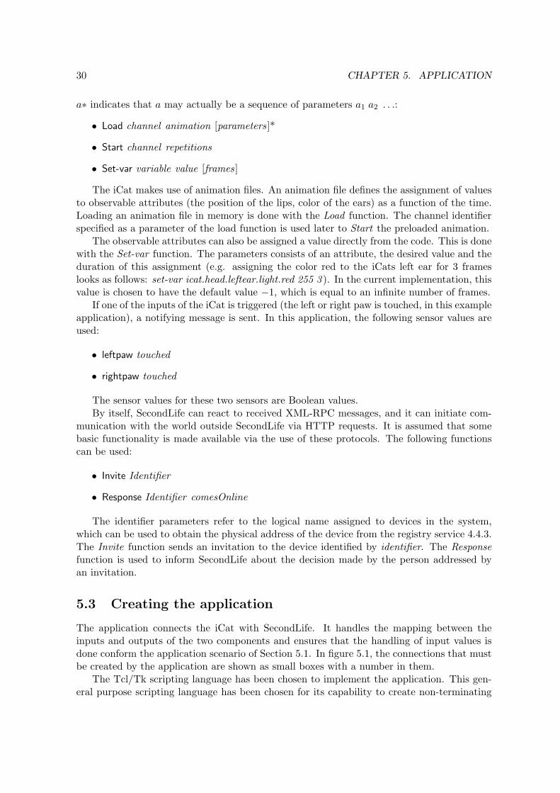
a∗ indicates that a may actually be a sequence of parameters a1 a2 . . .:
• Load channel animation [parameters]*
• Start channel repetitions
• Set-var variable value [frames]
The iCat makes use of animation files. An animation file defines the assignment of valuesto observable attributes (the position of the lips, color of the ears) as a function of the time.Loading an animation file in memory is done with the Load function. The channel identifierspecified as a parameter of the load function is used later to Start the preloaded animation.
The observable attributes can also be assigned a value directly from the code. This is donewith the Set-var function. The parameters consists of an attribute, the desired value and theduration of this assignment (e.g. assigning the color red to the iCats left ear for 3 frameslooks as follows: set-var icat.head.leftear.light.red 255 3 ). In the current implementation, thisvalue is chosen to have the default value −1, which is equal to an infinite number of frames.
If one of the inputs of the iCat is triggered (the left or right paw is touched, in this exampleapplication), a notifying message is sent. In this application, the following sensor values areused:
• leftpaw touched
• rightpaw touched
The sensor values for these two sensors are Boolean values.By itself, SecondLife can react to received XML-RPC messages, and it can initiate com-
munication with the world outside SecondLife via HTTP requests. It is assumed that somebasic functionality is made available via the use of these protocols. The following functionscan be used:
• Invite Identifier
• Response Identifier comesOnline
The identifier parameters refer to the logical name assigned to devices in the system,which can be used to obtain the physical address of the device from the registry service 4.4.3.The Invite function sends an invitation to the device identified by identifier. The Responsefunction is used to inform SecondLife about the decision made by the person addressed byan invitation.
5.3 Creating the application
The application connects the iCat with SecondLife. It handles the mapping between theinputs and outputs of the two components and ensures that the handling of input values isdone conform the application scenario of Section 5.1. In figure 5.1, the connections that mustbe created by the application are shown as small boxes with a number in them.
The Tcl/Tk scripting language has been chosen to implement the application. This gen-eral purpose scripting language has been chosen for its capability to create non-terminating

5.3. CREATING THE APPLICATION 31
iCat
2nd
Life
Start
Set-var
Response Invite
1 32
Load
rightpawleftpaw
Figure 5.1: The connections between the iCat and SecondLife. The numbers represent piecesof code.
applications and the ease in which new components and functionality can be added duringrun time. A short introduction to the syntax of the scripting language can be found inappendix A.
The first thing that needs to be done when creating an application is to localise and connectthe iCat and the SecondLife channel. From then on, the two services can be contacted andoutput values of these services are received. Establishing a connection is done in the followingway, assuming that Alice identifies her avatar by ‘AliceAvatar’ and Bob has named his iCat‘BobTheCat’:
set Alice [2ndLife AliceAvatar]set Bob [iCat BobTheCat]
Setting the colors of the iCats ears and paws is an essential part of the user experience,but resetting every colour when one colour is (possibly) changed is cumbersome at least. Toavoid this, a single function is defined that handles this for all LEDs:
proc SetBobColors {LE.R LE.G LE.B RE.R .. LP.R .. RP.R RP.G RP.B} {Bob Set-var icat.head.leftear.light.red $LE.RBob Set-var icat.head.rightear.light.green $LE.G...Bob Set-var icat.base.rightpaw.light.blue $RP.B
}
The function takes the RGB values (in the range 0..255) that are available for all userinput sensors. The names of the input sensors are abbreviated and represent the LeftEar,RightEar, LeftPaw and RightPaw respectively.
The second step in creating an application is defining connections between services. Ac-cording to the scenario, the interaction is initiated by Alice, by means of an invitation. Assoon as that invitation is received, the iCat should indicate that there is a message waitingfor Bob but wait with giving further explanation until user input is received.
# The connection that is labelled with a ‘1’ in the figurewhen Alice Invite Bob {# Indicate that there is a message waiting

32 CHAPTER 5. APPLICATION
SetBobColors 0 0 255 0 0 255 ... 255
# Listen for user interactionwhen Bob rightpaw true {# Let the iCat wake upBob Load 1 "Awake.raf"Bob Start 1 1# Ask Bob if he wants to join AliceAskBob \{Do you want to join Alice online?}\{Alice Response Bob Yes}\{Alice Response Bob No}
}}
As soon as Bob presses the right paw of his iCat, the AskBob procedure is called. Thisprocedure is not available in the framework and it will have to be defined:
AskBob {question ifYes ifNo} {# Change the right paw to green and the left paw to redSetBobColors 0 0 0 ... 255 0 0 0 255 0Bob Set-var icat.speech.text $question
# The connection that is labelled with a ‘2’ in the figurewhen Bob leftpaw true [subst {$ifNowhen Bob rightpaw true {}when Bob leftpaw true {}
}]# The connection that is labelled with a ‘3’ in the figurewhen Bob rightpaw true [subst {$ifYeswhen Bob rightpaw true {}when Bob leftpaw true {}
}]}
In Tcl/Tk, functions can easily be passed as strings and created, deleted and modifiedduring run time. This language feature is used repeatedly in the application logic describedabove. Functionality is only assigned to user inputs when this is necessary. If not, the eventhandlers are reset like it is done in the AskBob function.
The application in this chapter is not very complicated. It involves only two services thatare combined in a fully sequential scenario. This has been done intentionally, such that thebehaviour of the program can be grasped easily. However, the way in which the applicationlogic is presented in this chapter is representative for the way in which the platform can beused to develop more interesting applications.

Chapter 6
Verifying data replication
In a real-world implementation of the registry described in section 4.4.3, a single machinemight not be capable of handling all requests. Instead, several systems are placed in acluster, named a web farm. In such a setup, the computational load can be balanced betweensystems, allowing for a more responsive system. A web farm allows to perform admissioncontrol and load balancing of transactions to available nodes [2, 33].
Load balancing is a powerful technique, distributing computation intensive tasks froma single point of entry to several systems. With load balancing, systems can handle moresimultaneous requests than are possible when a single machine is used. To guarantee dataconsistency, all nodes can request the required data from a single machine, being the centraldata storage. Alternatively, the information can be shared among all connected machines anda data replication protocol can be used to keep the data consistent.
In this chapter, a protocol by Kemme and Alonso [22] regarding data consistency ispresented. This protocol is modelled with mCRL2 and this model is used to verify severalrequirements on a data replication protocol.
6.1 Data consistency between distributed hosts
Data replication protocols orchestrate the handling of transactions, which are lists of readand write actions on items. The first categorisation of these type of protocols is into lazy,where replication is handled after a transaction is completed and eager, where replication ishandled between the boundaries of a transaction. Although the lazy variant allows for fasterresponse times, the eager variant leads to more consistent data [21, 4].
In a distributed database model, there is a collection of n nodes that keep a local recordof data items and their values. Kemme and Alonso assume a static collection of nodes andassume that all data elements are available locally to every node.
Communication between nodes takes place via a group communication protocol, whichhandles communication and ordering. The messages are assumed to be totally ordered, mean-ing that all messages are delivered in exactly the same order at all nodes. A different orderingwould be a causal one, where transactions are guaranteed to be delivered in the same orderat all nodes if and only if their order is relevant to the consistency of the data. There arevarious approaches to implement totally ordered group communication protocols [22, 35].
Data consistency between nodes is guaranteed if all write operations, the only type ofoperation that influence consistency, are executed in the same order at all nodes. In that
33

34 CHAPTER 6. VERIFYING DATA REPLICATION
sense, it would appear to an outside observer as if only one machine is maintaining the data.A protocol that behaves as if it consists of a single machine is called 1-copy-serializable.
6.2 A serializable protocol
Kemme and Alonso present three different protocols in their article [22], of which only onewill be modelled here. The serializable approach has been taken in favour of cursor stabilityand snapshot isolation since it is the only one of the three protocols that prevents all possibleisolation problems described by Berenson et al. [22, 3]. Be aware that the algorithm doesnot give any guarantees on the handling of transactions, due to the decision that every non-committed read action should be aborted whenever a write action on the same item is received.The other two protocols do not share this behaviour, but allow inconsistencies.
To avoid any ambiguity between the representation here and the protocol described byKemme and Alonso, it is presented in figure 6.1 as it was listed in their article [22]. Thealgorithm works on items in the database and an arbitrary data item will be indicated by X.
The lock manager of each node N controls and coordinates the operation requests ofa transaction Ti in the following manner:
1. Local Reading Phase: Acquire local read lock for each read operation ri(X). Deferwrite requests wi(X) until end of reading phase.
2. Send Phase: If Ti is read-only, then commit. Else bundle all writes in WS i andmulticast it (total order service).
3. Lock Phase: Upon delivery of WS i , request all locks for WS i in an atomic step:
a. For each operation wi(X) in WS i :i. If there is no lock on X, grant the lock.ii. If there is a write lock on X or all read locks on X are from transactions
that have already processed their lock phase, then enqueue the lock request.iii. If there is a granted read lock rj(X) and the write set of WS j of Tj has not
yet been delivered, abort Tj and grant wi(X). If WS j has already beensent, then multicast abort message aj (basic service).
b. If Ti is a local transaction, multicast commit message ci (basic service).
4. Write Phase: Whenever a write lock is granted perform the corresponding operation.
5. Termination Phase:
a. Upon delivery of a commit message ci: Whenever all operations have beenexecuted commit Ti and release all locks.
b. Upon delivery of an abort message ai: Undo all operations already executedand release all locks.
Figure 6.1: Protocol for replication with serializability by Kemme and Alonso, taken from [22]
In order to model the protocol, the processes of which a node Ni consists, as well as theactions that can occur should be defined. The separation into processes has been done byKemme and Alonso [22]. Deciding which actions to include is done based on actions that arerelevant to the requirements of the protocol. In the following section, the requirements willbe introduced.

6.3. REQUIREMENTS OF THE SYSTEM 35
6.3 Requirements of the system
Kemme and Alonso list three properties that must hold for an eager replication protocol tobe correct. The correctness of these properties is proven by applying structural inductionon the shape of the protocol. Although this is sufficient, Kemme and Alonso do not definecritical sections in their protocol, nor do they consider the behaviour of phases other than thelock phase in the analysis of their protocol in very much detail. By modelling the protocol inmCRL2, possible ambiguities are identified and remedied.
In this section, the desired properties formulated by Kemme and Alonso are reformulatedas smaller and easier verifiable requirements on the model.
6.3.1 Absence of deadlock
One of the most desirable features in a protocol is the absence of deadlock. A model is said tocontain a deadlock state if there is at least one configuration possible that is reachable froman initial state and from where no actions can be performed. A model is called deadlock freeif no such state exists.
In a data replication protocol like the one considered here, no deadlock states should occur.For the original protocol description, Kemme and Alonso [22] proved that this is indeed thecase. Although they did not put too much stress on the way in which the other phases shouldbe implemented, the absence of deadlock should hold in the model of the protocol as well asin the original protocol.
Unfortunately, this does not seem to be the case for the model. In the protocol, transac-tions must be identifiable during the lifespan of the transaction. In order to make the systemdeadlock free, identifiers assigned to transactions should be released as soon as all nodes havecompletely finished the transaction. This way, the identifier can be reused and the numberof used transaction identifiers can be limited, making the state space feasible.
In the current protocol, there is no place where it is known if all nodes have fully handleda specific transaction. Without this information, it is not possible to reuse a transactionidentifier, since this may lead to duplicate transaction identifiers on nodes in the system.
Without modifying the protocol, the absence of deadlock can only be approximated byformalising several properties that make it reasonable that no deadlock states exist. Thefollowing requirements are added for that purpose:
req 1.1 Every transaction identifier is assigned only once and to only one node.
req 1.2 Every local transaction is eventually finished
req 1.3 Every lock that is requested on any node is eventually released
6.3.2 Atomicity of transaction
When a node receives a transaction request, this request is called local to that node. Giventhat progress is made, at some point in time the transaction enters its lock phase at the localnode and a decision is made whether the transaction should be committed or aborted.
Naturally, if consistency of data is of any interest, this decision should be followed by allother nodes and this is expressed in the following requirements:
req 2.1 The decision to abort or commit a transaction is always made.

36 CHAPTER 6. VERIFYING DATA REPLICATION
req 2.2 The decision to abort or commit a transaction is made by the node to which thetransaction is local.
req 2.3 If a transaction has been committed by the local node, then all nodes commit thistransaction.
req 2.4 If a transaction has been aborted by the local node, then all nodes abort thistransaction.
req 2.5 The decision to abort or commit a transaction is not made by a node to whichthe transaction is not local.
6.3.3 1-Copy-serializability of the protocol
One of the main criteria for correctness of an eager replication protocol is the 1-copy-serializability [4]. This involves the system to behave as a single database forcing differentconcurrent transactions to be coordinated in such a way that their execution is equivalentwith the sequential execution on a single copy of the data.
This involves only the write operations on the database, since the order in which readoperations are executed does not influence the external behaviour of the database. In orderto have 1-copy-serializability, all write operations should be operated on all nodes and shouldbe operated in the same order.
More precisely, if the following requirements hold, then the protocol is 1-copy-serializable:
req 3.1 If transaction t is going through its lock phase before transaction t′ on node N ,then this order holds for all nodes.
req 3.2 All nodes request write locks for all transactions that are multicasted.
6.4 Model checking tools
To help in verifying required properties of the model, model checking algorithms can beused. A model checking algorithm takes a model M = (States, Init ,Actions,Relations) anda formula f describing a property as input parameters. The result of such an algorithm isa set of states m, m ∈ M for which the property described in f holds. To verify that aspecific property is globally true, the number of states that is returned by the model checkingalgorithm should be equal to the number of states in the model.
There are several languages available to define the required properties of a model. Fairlywell known is CTL*, with LTL and CTL as two subsets of this language. CTL*, as wellas the subsets, works on Kripke structures, which define a set of states S, a set of initialstates I, relations between nodes R and a labelling function L : S → 2AP , giving the atomicpropositions that hold in the supplied state. When not the atomic propositions of a particularstate but the transitions between states are of interest, µ-calculus can be used.
In the mCRL2 tool set, there are (experimental) tools available for verification. Thesetools use an extension to the µ-calculus, allowing the inclusion of actions with parametersin the formula (First Order Modal µ-calculus). When the term µ-calculus is used in theremainder of this chapter, this extension is meant instead. The formal syntax is currently

6.4. MODEL CHECKING TOOLS 37
a ba
b a
a ba
b a
a ba
b a
Figure 6.2: A simple transition model, including the iterations required to find a fixpointcontaining all states with a future a transition.
only documented in an internal document [28] due to the currently experimental nature ofthe tool set. Some examples of the syntax are given by Groote and Willemse [14].
6.4.1 An introduction to µ-calculus
The µ-calculus is a mathematical language that can be used to define propositions on statesand transactions between states in a model. The model M = (S, T, L) on which µ-calculusformulae are evaluated consists of all states S of the model, the transitions between states Tand a mapping of atomic propositions that are true in a particular state L.
In model checking, the validity of a property p in a state s may depend on the validityof property p′ (p and p′ may be equivalent) in state s′. When state s validates p, changes inthe collection of states where property p′ holds influences the validity of p in s. As a remedy,states and properties are re-evaluated until no further changes occur. The resulting collectionof states is called a fixpoint and this concept is frequently used in the formalisation of therequirements.
In µ-calculus, there are two different types of fixpoints. The least fixpoint operator µreturns the fixpoint that is the least among all fixpoints. The greatest fixpoint operator νreturns the fixpoint that is the maximum among all fixpoints. Finding the fixpoint of a µ-calculus formula in a model is done by giving an approximation of the states in which theprocess holds, and refine this approximation by repeating the process. In a finite model, thisprocess is guaranteed to end. Additionally, the provided formula should be monotonic in itsbehaviour in order to be semantically meaningful [10].
Two other operators that are available, apart from the propositional logic operators likeconjunction, disjunction and negation, are the [a] and 〈a〉, with a an action. They are usedto express conditions on transitions and the states to which they lead. Given that JfKMerepresents the interpretation of f in the model M :
J〈a〉 fKMe ={
s|∃[s
a→ t and t ∈ Jf KM e]}
J[a] fKMe ={
s|∀[s
a→ t and t ∈ Jf KM e]}
As an example calculation of a µ-calculus formula, the following requirement will berewritten and verified over the simple model, presented in figure 6.2.

38 CHAPTER 6. VERIFYING DATA REPLICATION
1. All paths inevitably include an a-labelled transition.
Rewriting this requirement to an equivalent µ-calculus formula results in the following:
µX. 〈>〉> ∧ [¬a] X
If this formula is approximated once for every state present in the model of figure 6.2,only a single state will match the formula. During the second approximation, using the statesfound in the first approximation as the set of states X, the initial state is added to the set ofresulting states as well. Further evaluations do not add any states to this set, making the twostates currently found the fixpoint of the formula. Since the initial state is element of the setof states that are the result of evaluating the formula, it can be stated that, from the initialstate, all paths must include an transition labelled with an a.
6.4.2 The mCRL2 tool set
The mCRL2 tool set is still under active development and is expected to contain some defects.As such, the exact configuration as it was used during modelling and verification is presentedhere. This can safely be skipped for readers not familiar with this tool or uninterested in theversion numbers and is included for reference purposes only.
The tools used are listed in table 6.1. The version number that is given was retrieved bypassing the ‘–version’ parameter to the executable.
tool arguments versionmcrl22lps revision 3599-release-sharedlps2lts revision 3599-release-sharedltsconvert -u revision 3599-release-sharedltsgraph revision 3599-release-sharedlps2pbes -f revision 3599-release-sharedpbes2bool revision 3599-release-shared
Table 6.1: The context in which the verification has taken place.
The language mCRL2 is a specification language used to specify and analyse the behaviourof distributed systems and protocols [9]. A model written in this specification language canbe converted into an equivalent linear process with the use of mcrl22lps. This linear processcontains no parallelism and is the basis input for most tools in the tool set. In the analysisof the model in this chapter, two tools that use a linear process as an input have been used.For the model checking, the linear process together with a formula in µ-calculus can be usedto generate a Parameterised Boolean Equation Systems (PBES) with the lps2pbes tool. Thevalidity of the formula in the model can be obtained by solving the PBES, resulting in aBoolean value, with the pbes2bool tool. The linear process can also be used to generate thestate space of the model with the lps2lts tool. The resulting state space can be rewritten inanother format, possibly after applying a minimising method such as branching bisimulation,with the ltsconvert tool. Visualising the state space in a two-dimensional graph can be donewith the ltsgraph tool.

6.5. THE ACTIONS OF THE MODEL 39
6.5 The actions of the model
To verify the requirements stated in section 6.3, these requirements must be formalised usingthe µ-calculus. In µ-calculus, the exact names of transitions, and their parameter values, playan important role. Consequently, in order to formalise the requirements, the actions that areavailable in the model must be known. In this section, the available actions will be described.
6.5.1 The observable actions
The communication with external processes is shown in figure 6.3, where arrows have beendrawn wherever Kemme and Alonso indicate communication with processes outside the node.
Node
UR
UQ Send
Receive
Database
UserGroup
communcation
medium
Figure 6.3: The communication of a node with external processes
There are three different processes with whom the node is communicating. The exactactions and their parameters will be described in the following subsections.
Communication between node and user
Users are processes that are interested in the information that is available in the database.To retrieve that information, the user process requests the information from a single nodethat is part of the system. Any request from a user process, named a transaction, consists ofa list of read and write operations on one or more items in the database.
In communication with the node, a user process can send a request and receives a resultwhen the request is handled. These two actions are considered to be the only observableactions of the user process, having the following names and parameters:
Action name: UQ(n:Node, t:Transaction)Description: The action UQ (User Query) contains a transaction request
t. The type Transaction represents an arbitrary list of readand write operations on items in the database.
Action name: UR(n:Node, t:Transaction, s:Status)Description: The action UR (User Result) communicates with the user
the result of evaluation of transaction t. The status param-eter s is a value indicating whether or not the transactionwas committed or aborted.

40 CHAPTER 6. VERIFYING DATA REPLICATION
In these descriptions, currently undefined types are used. These types will be defined afterthe requirements have been formalised. In this way, the number of values that belong to aspecific type can be minimised such that the size of the state space that is generated fromthe model can be kept reasonably small.
Communication between node and network
The group communication medium shown in figure 6.3 is assumed to offer reliable and in-order delivery of messages to all nodes (including the sending node) connected to the medium.Following the protocol description in figure 6.1, two different types of messages, transactionsand the decision to abort or commit by the local node, can be sent to all other nodes via thegroup communication medium. In the model, these communication actions are representedby the following actions:
Action name: Send(n:Node, t:Transaction)Description: Sends transaction t to all nodes connected to the communi-
cation medium. All communication initiated by this opera-tion is considered to be reliable and totally ordered.
Action name: Send(n:Node, t:Transaction, r:Result)Description: Sends the decision to abort or commit transaction t to all
nodes connected to the communication medium. Communi-cation initiated by this operation is considered to be reliablebut does not have to arrive in-order.
Action name: Receive(n:Node, t:Transaction)Description: Indicates transaction t to be received from the group com-
munication medium by the node identified by n.Action name: Receive(n:Node, t:Transaction, r:Result)Description: Indicates that node n receives the decision r to abort or
commit transaction t.
Communicating with the database
The communication with the database is handled by the Lock Manager. As such, no directcommunication with the database is required and it is therefore omitted from figure 6.3. Theinternal communication with the lock manager will be introduced next.
6.5.2 The internal actions
Apart from the behaviour that is observable from the outside of the node, there is also someinteresting functionality hidden inside the node. The communication, transaction and lockmanager process of the node each run in their own thread but can communicate informationand requests whenever this is required. The interfaces of the three internal processes shownin figure 6.4 will be described here.
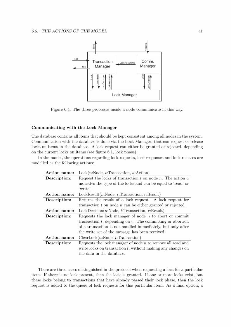
6.5. THE ACTIONS OF THE MODEL 41
Transaction
Manager
Comm.
Manager
UQ
UR
Lock
LockD
ecis
ion
LockF
inis
h
Sen
d
LockResultWS
Lock Manager
Receiv
e
Lock
LockD
ecis
ion
LockR
esultW
SFigure 6.4: The three processes inside a node communicate in this way.
Communicating with the Lock Manager
The database contains all items that should be kept consistent among all nodes in the system.Communication with the database is done via the Lock Manager, that can request or releaselocks on items in the database. A lock request can either be granted or rejected, dependingon the current locks on items (see figure 6.1, lock phase).
In the model, the operations regarding lock requests, lock responses and lock releases aremodelled as the following actions:
Action name: Lock(n:Node, t:Transaction, a:Action)Description: Request the locks of transaction t on node n. The action a
indicates the type of the locks and can be equal to ‘read’ or‘write’.
Action name: LockResult(n:Node, t:Transaction, r:Result)Description: Returns the result of a lock request. A lock request for
transaction t on node n can be either granted or rejected.Action name: LockDecision(n:Node, t:Transaction, r:Result)Description: Requests the lock manager of node n to abort or commit
transaction t, depending on r. The committing or abortionof a transaction is not handled immediately, but only afterthe write set of the message has been received.
Action name: ClearLock(n:Node, t:Transaction)Description: Requests the lock manager of node n to remove all read and
write locks on transaction t, without making any changes onthe data in the database.
There are three cases distinguished in the protocol when requesting a lock for a particularitem. If there is no lock present, then the lock is granted. If one or more locks exist, butthese locks belong to transactions that have already passed their lock phase, then the lockrequest is added to the queue of lock requests for this particular item. As a final option, a

42 CHAPTER 6. VERIFYING DATA REPLICATION
lock request for a transaction that has not yet passed its lock phase can be present. Thislock request must belong to a local transaction (it can only be a read lock, which are onlyobservable locally) and as such, this transaction must be aborted.
The three different decisions are represented by the following actions in the model:
Action name: NoLocks(n:Node, t:Transaction)Description: Internal operation, indicates that there are no locks that
conflict with the current lock request on node n.Action name: ConflictingLocks(n:Node, t:Transaction)Description: Internal operation, indicates that there is a lock request that
conflicts with transaction t on node n.Action name: NoConflictingLocks(n:Node, t:Transaction)Description: Internal operation, indicates that there is no lock request
that conflicts with transaction t on node n.
As soon as the lock manager has received the write set and the decision message of aparticular action, it can handle the transaction and release the locks. This is done with thefollowing internal action:
Action name: removeLocks(n:Node, t:Transaction)Description: Internal operation, executed when both the decision and the
lock request of a particular transaction t have been receivedon node n.
Communication with the communication manager
The communication manager is a process that receives messages from the network. As soonas a write set or result message is received, it is handled as is described in the protocol offigure 6.1 (the lock phase and termination phase).
Most of the interface of the communication manager is symmetrical to that of the lockmanager. There is one action that allows the communication manager to inform the trans-action manager of the decision made by the lock manager on a write set of a particulartransaction.
Action name: LockResultWS(n:Node, t:Transaction, r:Result)Description: Communicates the result r of requesting the locks for the
write set of transaction t to the transaction manager ofnode n.
Communication with the transaction manager
In the transaction manager, the operations that are assigned to the different phases of theprotocol presented in figure 6.1 are executed. It is the only place where the distinction betweenlocal and remote transactions is made and messages to all other nodes are sent from here.

6.6. FORMALISING THE REQUIREMENTS 43
Any conflicting lock is communicated to the transaction manager. The transaction man-ager can send an abort message to the group communication medium if required. The actionallowing to inform the transaction manager is modelled as follows:
Action name: RejectLock(n:Node, t:Transaction)Description: Tells node n that transaction t, which is a local transaction
that has not yet passed its lock phase, must be aborted.
6.6 Formalising the requirements
With the observable actions defined, the requirements can be formalised into µ-calculus. Theformalisation of requirements will be done in this section, followed by the model of the protocoland the evaluation of the requirements in the following sections.
The requirement identifiers used in this section refer to the identifiers used in section 6.3,all actions used are presented in section 6.5. Whenever the relation between a requirementand its representation in µ-calculus is not directly clear, the reasoning to get to this formulais given as well.
6.6.1 Abstractions of the model
In order to keep the state space generated by the model feasible, some abstractions will haveto be made. Since the abstractions might be usable as assumptions in the verification of therequirements, they are presented here before the actual formalisation of the requirements.
A transaction is a list, containing any number and order of read and/or write operations.As a result, the Transaction data type consists of an infinite number of data elements. Usingthem when generating a state space results in a state space explosion from the initial stateon.
Fortunately, the exact operations that are part of an transaction are of little importanceto the way in which the protocol operates. It is required that transactions have an identifierand that this identifier is unique. An enumerable type is sufficient, since the number oftransactions that will be initiated by the user process is bounded. It is assumed that in theinitial state a random distribution of locks is present. This way, the general behaviour of theprotocol can be observed with only a bounded number of transactions initiated by users ofthe system.
6.6.2 Absence of deadlock
req 1.1 Every transaction is uniquely identified, so the requirement holds if no assignmentof a transaction identifier t to a node, represented in the model by the action UQ(t) is followedby the assignment to the same transaction to any, possible other, node.
In µ-calculus, the requirement is formalised as follows:
νX. [>] X ∧ ∀n:Node∀t:Transaction [UQ(n, t)] (νY. [>] Y ∧ [∃n′:NodeUQ(n′, t)]⊥)

44 CHAPTER 6. VERIFYING DATA REPLICATION
req 1.2 A transaction t is finished if the action that introduced the transition in the system,UQ(n,t), is inevitably followed by a corresponding action UR(n′,t), for some n, n′ ∈ Node.A transition is inevitable from a particular state s if all paths starting from s contain a states′ from which the only available transition is the action UR(m). Modelling this in µ-calculusresults in the following formula:
νX. [>]X ∧ ∀t:Transaction [∃n:NodeUQ(n, t)] (µY. 〈>〉> ∧ [¬∃n′:Node∃p:PhaseUR(n′, t, p)]Y )
req 1.3 All locks are released if, for any node, every call to Lock(node, transaction, a), fora ∈ {read,write} is inevitably followed by a call to ClearLock(node, transaction) or remove-Locks(node, transaction).
Modelling this in µ-calculus results in the following formula:
νX. [>] X ∧ ∀n:Node∀t:Transaction∀a:Action [Lock(n,t,a)] (µY. 〈>〉> ∧ [¬(removeLocks(n, t) ∨ ClearLock(n, t))]Y
)
6.6.3 Atomicity of transactions
req 2.1 All transactions that are offered to the system will eventually be committed oraborted. Note that this requirement is a less restrictive case of req 2.2. If the validity ofreq 2.2 can be shown, the validity of req 2.1 is proven automatically.
req 2.2 The decision to abort or commit a transaction should be always made and is madeby the node to which the transaction is local. The result of this decision is communicated tothe user by the UR(node, transaction, decision) action. If this requirement is formalised tothe µ-calculus, the following formula is obtained:
νX. [>] X ∧ ∀n:Node∀t:Transaction [UQ(n, t)] (µY. 〈>〉> ∧ [¬∃p:PhaseUR(n, t, p)]Y )
Apparently, this is roughly same formula as was obtained for req 1.2, additionally re-quiring that the transaction response is send by the same node that initially received thetransaction request. It might be interesting to further restrict the requirement to the casewhere the decision is communicated to the user process exactly once, and that no otherprocess communicates this decision to the user process.
νX. [>] X ∧ ∀n:Node∀t:Transaction [UQ(n,t)] (µY. 〈>〉> ∧ [¬∃p:PhaseUR(n, t, p)]Y ∧ [∃p:PhaseUR(n, t, p)] (νZ. [>]Z ∧ [∃p:PhaseUR(n, t, p)]⊥)∧νY. [>] Y ∧ ∀n′:Node. (n 6= n′) ⇒ [∃p:PhaseUR(n′, t, p)]⊥
)
This formula expresses that every action UQ(n,t) is inevitably followed by exactly oneaction UR(n,t,p) and that there is no action UR(n′,t,p), for n′ 6= n.

6.6. FORMALISING THE REQUIREMENTS 45
req 2.3 and req 2.4 The effect of a transaction is supposed to be made permanent afterthe transaction locks have been released. This holds both for the aborted and the committedtransactions. The decision of a local node can be made silently, if the write set of thattransaction has not yet been sent to the group communication medium. Otherwise, the effectof a transaction must be made permanent on all nodes. This is formalised as:
∀n:Node ( νX. [>] X ∧ ∀n′:Node∀t:Transaction∀r:Result [Send(n′, t, r)] (µY. 〈>〉> ∧ [¬removeLocks(n, t, r)]Y
) )
This formula expresses that every action Send(n′,t,r) is eventually followed by a removeLocks(n,t,r)action, for every n ∈ Node.
req 2.5 This requirement holds if no node except the node to which the transaction is localexecutes the action Send(node, transaction, result)
νX. [>] X ∧ ∀n:Node∀t:Transaction [UQ(n, t)] (νY. [>] Y ∧ ∀n′:Node(n 6= n′) ⇒ [∃r:ResultSend(n′, t, r)]⊥
)
6.6.4 1-copy-serializability
req 3.1 Formulating this requirement in the µ-calculus is more complicated than suggestedby the possible number of sequences. In verifying this requirement, only the relative order ofthe Lock(n, t, write) transition label instances, for n ∈ Node, t ∈ Transaction, are interesting.
The order between instances of this transition label can be obtained by hiding all actionsother than the Lock(n,t,write) action and calculating the weak trace equivalent graph of theoriginal model. In a weak trace equivalent graph, all internal (hidden) actions that remainafter branching bisimulation are simply removed, effectively minimising the graph to theactions that are observable.
This results in the graph shown in figure 6.5. Note that a currently unknown transitionlabel, namely cLockW is shown. This label represents the simultaneous execution (commu-nication) of the Lock(n,t,a) action by two processes, with a = write. This modification wasrequired to distinguish between the read and write parameter values and does not influencethe behaviour of the model.
It follows from the graph in figure 6.5 that write locks are requested in the same order onevery node, which validates the requirement.
Alternatively, a parameterised µ-calculus formula has been suggested by Tim Willemse.According to his experiments, this formula expressed the requirement and was evaluatedas being valid in the model. Because the tools used in the verification used for the otherrequirements were incapable of reproducing this result, the formula has been included inappendix B but will not be presented here.
req 3.2 For this requirement to hold, all possible paths must include the action Lock(n, t,write) for all n ∈ Node and every t ∈ Transaction that has been multicasted via Send(node,t). Formalising this in µ-calculus results in the following:

46 CHAPTER 6. VERIFYING DATA REPLICATION
cLockW(N2, t1)
cLockW(N
1, t2)
cLockW(N2, t2)
cLockW(N1, t1)
cLockW(N2, t2)
cLockW(N
1, t1)
cLockW(N2, t1)
cLockW(N1, t2)
cLockW(N2, t1)
cLockW(N1, t1)
cLockW(N1, t2)
cLockW(N1, t1)
cLockW(N
2, t2)
cLockW(N1, t2)
cLockW(N
2, t1)
cLockW(N2, t1)
cLockW(N
1, t1)
cLockW(N2, t2
)
cLoc
kW(N
1, t2
)
cLockW(N2, t2)
cLockW(N1, t1)cLockW(N
2, t1)
cLockW(N1, t2)cL
ockW
(N2,
t2)
Figure 6.5: A weak trace equivalent version of the model in which all actions other thancLockW are hidden.
∀n:Node ( νX. [>] X ∧ ∀n′:Node∀t:Transaction [Send(n′, t)] (µY. 〈>〉> ∧ [¬Lock(n, t, write)]Y
) )
6.7 Modelling the protocol
Knowing the actions that are present in the protocol, together with their parameters, it isnow possible to model the protocol using the mCRL2 modelling language. In this section, thenode process is modelled. The node process consists of three smaller processes as was shownin figure 6.4.
Within the processes, a distinction is made between sending and receiving an action, orthe communication of that action if both are performed simultaneously. This distinction ismade by prefixing the action with the characters s, r and c.
In the verification of the protocol, not all possible configurations can be considered. There-fore, a configuration is selected that is sufficiently large to be representative yet small enoughto result in a feasible state space. In this configuration, the system consists of two nodes andis given two transactions.
Considering two nodes is sufficient in modelling the behaviour of the protocol, since theonly distinction between transactions is made in terms of ‘local’ versus ‘remote’. Two transac-

6.7. MODELLING THE PROTOCOL 47
tions is the minimal number of transactions required to ensure that a conflicting lock requestsmay occur, which is essential in the data replication protocol.
6.7.1 Types used in the model
In the description of the actions, several types that are not normally available in the mCRL2language are used. Before the different processes will be modelled, the more interesting typesare introduced.
Every node consists of three different processes that communicate. The different processesmust be able to identify the other processes that belong to the same node. Also, the groupcommunication protocol uses this information to address the different nodes.
Node = struct N1 | N2;
As observed in section 6.6.1, transactions need to be identified by a unique identifier. Asexplained earlier, there are only two transactions required so this is easily modelled.
Phase = struct read | send | lock | committed | aborted;Transaction = struct t1 | t2;TransactionItem = struct tr(identifier:Transaction, phase:Phase);
The delivery of messages by the group communication medium requires more informationthan there is present in the TransactionItem type. The node to which to send the message isrequired to guarantee that a message is sent at most once. This type is defined as follows:
TransactionQueue = struct tq(node:Node, transaction:TransactionItem);
6.7.2 Functions
Processes in the model may manipulate the values that are passed as parameters. For thispurpose, several functions have been defined. Their implementation in mCRL2 can be foundin appendix B.
The filter operation takes a list L and a desired value v for property p as its arguments andreturns a list of matching elements. With B representing list concatenation and [a1, a2, . . .]representing a list with elements a1, a2, . . . , the filter function is defined recursively as follows:
filter(L, v) ={
filter(tail(L), v) if p(head(L)) 6= v[head(L)] B filter(tail(L), v6) if p(head(L)) = v
The remove operation takes a list L and a single element t of the same type as the elementsin the list. This is defined recursively as follows:
remove(L, t) ={
[head(L)] B remove(tail(L), t) if head(L) 6= tremove(tail(L), t) if head(L) = t
The third operation, update, takes a list L, a single element t of the same type as theelements of L and a value v for known property p. The update(L,t,v) operation is definedrecursively as follows:
update(L, t, v) ={
[head(L)] B update(tail(L), t, v) if head(L) 6= t[head(L)(p := v)] B update(tail(L), t, v) if head(L) = t

48 CHAPTER 6. VERIFYING DATA REPLICATION
6.7.3 A single node
A node is the parallel composition of three processes, as shown in figure 6.4. In this section,these three processes will be defined.
The transaction manager
The transaction manager keeps score of the states of the transactions that are local to thisnode.
When a new transaction is received from the user process, it is added to the list of localtransactions. According to the protocol, the transaction is waiting to enter its read phase.
proc NODE_TRANSACTION_MANAGER(n:Node, local:List(TransactionItem)) =sum t:Transaction .rUQ(n,t) .NODE_TRANSACTION_MANAGER(n,local ++ [tr(t,read)])
As soon as a transaction has entered its read phase, the read locks for the transactionare requested. Read locks are always granted eventually and the transaction is marked to beready to enter its send phase.
+ sum t:Transaction .(tr(t,read) in local)-> sLock(n,t,r) .
sum r:Result .rLockResult(n, t, r) .NODE_TRANSACTION_MANAGER(n, update(local, tr(t,read), send))
<> delta
When the transaction manager allows a transaction to enter its send phase, the transac-tion is communicated to the group communication medium. The transaction has succesfullyrequested read locks and is waiting for the Write Set message to be delivered.
+ sum t:Transaction .(tr(t,send) in local)-> sSend(n,t) .
NODE_TRANSACTION_MANAGER(n, update(local, tr(t,send), lock))<> delta
The communication manager is running in parallel with the transaction manager. Whilehandling a local transaction, write sets of remote transactions can be received. When thisoccurs, write locks for this write set are requested by the communication manager.
These write locks may conflict with read locks of local transactions. If this is the case,the local transaction is aborted by the transaction manager. Two cases are distinguishedthat influence the way in which the conflict is handled. In the first case, the write set ofthe transaction has not yet been sent to the group communication medium. The user thatinitiated this transaction can be informed about the abortion of the transaction and it canbe removed from the list of local transactions.

6.7. MODELLING THE PROTOCOL 49
In the second case, the write set of the transaction has already been communicated to thegroup communication medium. The local node decides that the transaction causes conflictsand sends an abortion message to the group communication medium.
This behaviour is modelled in mCRL2 as follows:
sum t:Transaction .rRejectLock(n,t) . ((tr(t,send) in local)-> sLockDecision(n,t,abort) .
sClearLock(n,t) .sUR(n,t,aborted) .NODE_TRANSACTION_MANAGER(n, remove(local, tr(t,read)))
<> delta+(tr(t,lock) in local)-> sSend(n,t,abort) .
sUR(n,t,aborted) .NODE_TRANSACTION_MANAGER(n, remove(local, tr(t,lock)))
<> delta)
The communication manager handles the write sets of remote and local transactions. Theresult of the lock request of a write set influences the node to which the transaction is local incommitting or aborting the transaction. The communication manager does not know whichtransactions are local and communicates all lock request results to the transaction manager.
+ sum t:Transaction .sum r:Result .rLockResultWS(n,t,r) . ((tr(t,lock) in local)-> ((r == abort)
-> sUR(n,t,aborted)<> sUR(n,t,committed)
) .sSend(n,t,r) .NODE_TRANSACTION_MANAGER(n, remove(local, tr(t, lock)))
<> NODE_TRANSACTION_MANAGER(n, local)
The communication manager
The communication manager is waiting for the group communication medium to send amessage. As soon as a write set of a transaction is received, the appropriate locks are requestedfrom the lock manager. The result of this lock request is communicated with the transactionmanager, as explained in the previous section.
proc NODE_COMMUNICATION_MANAGER(n:Node) =sum t:Transaction .rReceive(n, t) .

50 CHAPTER 6. VERIFYING DATA REPLICATION
sLock(n, t, w) .sum r:Result .rLockResult(n, t, r) .sLockResultWS(n,t,r) .NODE_COMMUNICATION_MANAGER(n)
If the communication manager receives the result of transaction, it releases the locks thatbelong to that transaction.
sum t:Transaction .sum r:Result .rReceive(n, t, r) .sLockDecision(n,t,r) .NODE_COMMUNICATION_MANAGER(n)
;
The lock manager
The lock manager receives lock requests from the other two processes inside the node process.Lock requests for a read operation are always granted, but lock requests for write operationscan lead to conflicts with locks that are already present. In case of conflicting locks, theconflicting lock must be read lock for a local transaction (see the protocol). This localtransaction should be aborted via the transaction manager.
In the modelling of the lock manager, any arbitrary configuration of items and locks isassumed. A consequence of this is that no information about current locks needs to be stored,since it is unknown what the effect will be on the current configuration. However, when aconflicting lock is found, a previous transaction must be aborted. In the model, transactionsare stored in any of three parameters. The readLocks parameter is a list containing alltransactions that potentially have read locks present. As soon as a lock request for the writeset of a transaction is received, the transaction is removed from the list of readLocks (theread locks are still present, but cannot lead to conflicting situations any more) and added tothe list of write locks.
proc NODE_LOCK_MANAGER(n:Node, readLocks:List(Transaction),writeLocks:List(Transaction), releases:List(Transaction)) =
sum t:Transaction . (sum a:Action .rLock(n,t,a) . ((a == r) -> sLockResult(n,t,commit) . NODE_LOCK_MANAGER(n,readLocks ++ [t], writeLocks,releases)
<> (NoLocks(n,t) .sLockResult(n,t,commit) .NODE_LOCK_MANAGER(n, remove(readLocks,t),remove(writeLocks,t) ++ [t], releases)
+NoConflictingLocks(n,t) .

6.7. MODELLING THE PROTOCOL 51
sLockResult(n,t,commit) .NODE_LOCK_MANAGER(n, remove(readLocks, t),remove(writeLocks,t) ++ [t], releases)
+(#remove(readLocks,t) != 0)-> ConflictingLocks(n,t) .
sRejectLock(n, head(remove(readLocks, t))) .sLockResult(n,t,commit) .NODE_LOCK_MANAGER(n, remove(readLocks, t),remove(writeLocks,t) ++ [t], releases)
<> delta)
)
Apart from lock requests, the lock manager can also receive decisions about the abortionor committing of transactions. These decision messages must be stored until the write set ofthe corresponding transaction has been received.
When the transaction manager decides that a transaction should be aborted and the writeset of this transaction has not been sent to the group communication medium, its locks shouldbe removed. The ClearLock action handles this as follows:
+sum r:Result .rLockDecision(n,t,r) .NODE_LOCK_MANAGER(n, readLocks, writeLocks, releases ++ [t])
+rClearLock(n,t) . NODE_LOCK_MANAGER(n,remove(readLocks,t),remove(writeLocks,t),remove(releases,t)
)
Eventually, both the write set and the decision of a single transaction have been received.At this point in time, the decision can be applied to the local copy of the data and the lockscan be removed.
+(t in writeLocks && t in releases) ->removeLocks(n,t) . NODE_LOCK_MANAGER(n,remove(readLocks,t),remove(writeLocks,t),remove(releases,t)
)<> delta
);

52 CHAPTER 6. VERIFYING DATA REPLICATION
6.7.4 External processes
The data replication protocol must work for any number of nodes, so in particular for asingle node. In practise, using a data replication protocol is only interesting if multiplenodes are present in the system. If the parallel execution of two node processes is evaluated,modifications of the protocol are required to solve problems with respect to giving uniqueidentifiers to transactions and providing total order group communication. To avoid thesemodifications of the protocol, a user process and group communication process are modelled,providing just enough functionality as is desired by the data replication protocol. In thissection, the two additional processes will be described.
The user
The user process represents a process that initiates transactions by sending a transactionquery to any node. The process takes a list of available transaction identifiers and uses everyidentifier exactly once.
In their protocol description, Kemme and Alonso did not limit the number of user processesto strictly one, nor did they define the way in which process identifiers should be used. Inthe model, the process description as presented here is convenient because it guarantees thatevery identifier is unique. Rewriting the model such that multiple user processes are involvedis straightforward and will not be further investigated in this chapter.
proc USER(t:List(Transaction)) =(#t > 0)-> sum n:Node . sUQ(n, head(t)) . USER(tail(t))<> delta;
Group communication
The group communication medium provides the functionality to broadcast a message to allnodes connected to the group communication medium. Additionally, all messages containinga transaction should be delivered in the same order at every connected node, where the orderof the messages containing the decision to abort or commit a transaction can be deliveredin any order. The group communication process can be split in two parts, one for receivingmessages from the nodes and one part to send the messages to all nodes:
The receiving part receives either Send(node, transaction) or Send(node, transaction, re-sult) messages from the nodes. In one atomic action, messages received are added to the endof the queue for every node in the system. This guarantees that the ordering of transactionsand results in the queue is the same for all nodes.
proc NETWORK(transactions: List(TransactionQueue),results: List(TransactionQueue)) =
sum n:Node . (sum t:Transaction . (rSend(n,t) .NETWORK(transactions ++ [tq(N1,tr(t,lock)), tq(N2,tr(t,lock))],results

6.8. EVALUATION OF THE REQUIREMENTS 53
)+sum r:Result . rSend(n,t,r) . ((r == abort)-> NETWORK(transactions,
results ++ [tq(N1,tr(t,aborted)), tq(N2,tr(t,aborted))])
<> NETWORK(transactions,results ++ [tq(N1,tr(t,committed)), tq(N2,tr(t,committed))]
))
)
The order in which transactions are delivered should be the same on all nodes. To guar-antee this, a filter is applied over all messages in the queue, returning the messages that areaddressed to a particular node in the same order as in the original queue. From the queuethat is the result of this filter, the head element is taken and the identifier of the transactionthat is on top of the queue is send to the node.
+(#filter(transactions, n) != 0)-> sReceive(n, identifier(transaction(head(filter(transactions, n))))) .
NETWORK(remove(transactions, head(filter(transactions, n))), results)<> delta+
The result messages that are broadcasted via the group communication protocol may bedelivered in any order, which is expressed by the following mCRL2-code.
sum t:Transaction . sum p:Phase . ((tq(n,tr(t,p)) in results)->( (p == committed)
-> sReceive(n,t,commit)<> sReceive(n,t,abort)
) . NETWORK(transactions, remove(results, tq(n,tr(t,p))))<> delta
);
All communication in mCRL2 is considered to be reliable, implying that messages thathave been communicated (i.e. the corresponding action has been performed) can be safelyremoved from the list of transactions.
6.8 Evaluation of the requirements
In the evaluation, a system with two nodes, handling two transactions is assumed. The statespace generated by the parallel composition of two node processes, a network process and auser process consists of 46876 states and 140722 transitions. There is only a single state in

54 CHAPTER 6. VERIFYING DATA REPLICATION
which deadlock holds, which is where the user process can no longer execute the UQ action.All other processes are in the same state as they were initially.
The formalisation of the requirements in the µ-calculus has been used in the generationof Parameterised Boolean Equation Systems (PBES), that have been evaluated. Followingthe results of this evaluation, all requirements are considered to be valid. This indicates thatthe model as it has been introduced in this chapter gives a correct implementation of thereplication protocol suggested by Kemme and Alonso.
The model described here only matches the protocol and does not fully match the imple-mentation used by Kemme and Alonso. Throughout their paper, several decisions are madeon the way a transaction is applied to the items in the data storage. The model generalisesover these decisions by combining them in a single action and it is possible that an actionactually represents several choices. Other differences may relate to the implementation ofthe side processes. In their protocol, Kemme and Alonso state that users can autonomouslydecide which node receives their requests. In the model, a single user process randomly dis-tributes transaction requests in order to uniquely identify a transaction. Different approachesare possible, but considered equivalent during the modelling. The group communication pro-tocol is more interesting. Kemme and Alonso frequently use the total order semantics of thegroup communication medium in their proves and arguments, but do not specify the protocolthat was used for this group communication medium.
Concluding, the desirable properties were proven to be valid for the presented model. Theexperimental nature of the tools that were used, together with the verbose description of theprotocol, spread over several pages and articles, makes it difficult to state that the same holdsfor the original protocol. This does not decrease the value of the verification done in thischapter, as it gives a concise description of the processes involved which can be used in actualimplementations of the protocol, but the results of the verification would be more interestingif the protocol and the model would be guaranteed to be identical.

Chapter 7
Conclusion
7.1 The proposed solution
The platform proposed in this thesis is a standard layered solution to a distributed application.There are three layers, each with its own functionality. The communication layer handlescommunication between the application and robotic devices or web services. The servicelayer handles all protocol specifics of the devices and services. In the application layer therelation between the devices and services is defined.
In the proposed platform, all different devices and web services are generalised to theshape of reactive services. This generalisation is very natural to (robotic) devices, but doesnot directly follow the service oriented model that is common for web services. A consequenceof the use of reactive services is that applications can be described a very natural way, basedon the inputs and outputs of the reactive services. This event based programming style isintuitive for the type of applications that are supposed to be developed on top of the platform.
The messages that are sent between services consist of plain text. Text can easily bemarshalled between programming languages and operating systems, making it a compatibleformat. An advantage of text messages is that they can both represent data and commands, ifa scripting language interpreter is used to evaluate incoming messages. By evaluating receivedtext, it is possible to add new functionality at run time or to bring the computation to thedata, resulting in lower network load and reducing response times.
7.2 Correspondence to requirements
During the beginning of the project, it was not clear which type of applications the platformshould support. Although several robotic devices and web services have been considered, itwas not straightforward to generalise an application description from their functionality thatwas more precise than the one described in Chapter 2.
The lack of an exact application description was an encouragement to make the platformas flexible as possible. This resulted in a platform where application logic can be distributedbetween the services or can run on a single machine as desired. Connections between servicesmay be created and removed during execution, matching the application developers needs atany point in time.
Regarding services as being reactive, no matter how they are exactly implemented makestheir usage very straightforward. An application developer will have to invest some time in
55

56 CHAPTER 7. CONCLUSION
figuring out the meaning of each input and output value, but the conceptual model behindthe creation of these type of applications is simple and flexible.
7.3 Future research
For simple applications the architecture suffices, but problems arise when connecting severalapplications to the same service (either a robotic device or a web service) and trying to use itsresources. The variety of different robotic devices and web services guarantees a wide varietyof available resources and interfaces. This type of information should be shared between theservice and the connected applications, such that these applications can adapt themselves tothe available resources. As an additional advantage, it would make the communicated scriptsas powerful as mobile agents.
A second element of future research is the search of an appropriate security model. Cur-rently, a security model has been implemented that is based on the Safe-Tcl model, whichconsists of a sandbox interpreter from which all potentially dangerous functionality has beenremoved. Also, the current model does not discriminate between different users of a service,granting all users the same limited amount of functionality. In the type of robotic devices andweb services that have been used in the development of a prototype, this limited flexibilityof the security layer didn’t cause any problems. However, a robotic device that closes thewindows of your home may benefit from a different security model.
As a third area of research, an advanced visual aid may be designed and implemented. Ithas been mentioned several times that the way in which the platform operates can be easilyvisualised. There are some remarks to be made about this statement. In general, visual aidsallow the programmer to define the relation between components as it is during compile time.In the proposed platform, the connections between components may change over time anddepending on previous computations. This complicates the way in which the process graphis visualised and the way in which application programmers can make changes to the graph.
7.4 Verification
Consistency becomes a problem as soon as multiple processes have access to the same infor-mation. When this information is distributed among the nodes, as is the case for web farms,the problem becomes even more apparent. Kemme and Alonso recognised this problem andprovided several protocols that promised to solve this problem.
In this thesis, one of these protocols has been modelled and evaluated. It appeared thatthe protocol itself was elegant and simple, but much of the underlying details and assumptionswhere hidden throughout their papers. These details and assumptions have been found anda model of their protocol has been described. Although the model lacks the elegance of theoriginal protocol, it is a more precise description of the solution proposed by Kemme andAlonso.
Several desirable properties of this protocol have been described, formalised and have beenevaluated. From this evaluation, the desired properties where shown to hold in the system.Although the tools are experimental and are likely to contain errors, the results intuitivelymatch the behaviour of the protocol and the model is considered to be a correct and conciserepresentation of the protocol.

Bibliography
[1] M. Allman. An evaluation of xml-rpc. SIGMETRICS Perform. Eval. Rev., 30(4):2–11,2003.
[2] J. Aweya, M. Ouellette, D. Y. Montuno, B. Doray, and K. Felske. An adaptive loadbalancing scheme for web servers. Int. J. Netw. Manag., 12(1):3–39, 2002.
[3] H. Berenson, P. Bernstein, J. Gray, J. Melton, E. O’Neil, and P. O’Neil. A critiqueof ansi sql isolation levels. In SIGMOD ’95: Proceedings of the 1995 ACM SIGMODinternational conference on Management of data, pages 1–10, New York, NY, USA,1995. ACM Press.
[4] P. A. Bernstein, V. Hadzilacos, and N. Goodman. Concurrency Control and Recovery inDatabase Systems. Addison-Wesley, 1987.
[5] A. D. Birrell and B. J. Nelson. Implementing remote procedure calls. ACM Trans.Comput. Syst., 2(1):39–59, 1984.
[6] E. Cecchet, J. Marguerite, and W. Zwaenepoel. Performance and scalability of ejbapplications. In OOPSLA ’02: Proceedings of the 17th ACM SIGPLAN conference onObject-oriented programming, systems, languages, and applications, pages 246–261, NewYork, NY, USA, 2002. ACM Press.
[7] C.-C. Chiang and C. W. Ford. Maintainability and reusability issues in corba-basedsystems. In ACM-SE 43: Proceedings of the 43rd annual Southeast regional conference,pages 275–280, New York, NY, USA, 2005. ACM Press.
[8] F. Dabek, N. Zeldovich, F. Kaashoek, D. Mazieres, and R. Morris. Event-driven program-ming for robust software. In EW10: Proceedings of the 10th workshop on ACM SIGOPSEuropean workshop: beyond the PC, pages 186–189, New York, NY, USA, 2002. ACMPress.
[9] T. U. Eindhoven. Webpage mcrl2 toolset. http://www.mcrl2.org, July 2007.
[10] E.M.Clarke, O. Grumberg, and D. Peled. Model Checking. MIT Press, December 1999.
[11] C. Flynt. Tcl/Tk: A developer’s guide. Harcourt Publishers Ltd, 2003.
[12] A. Geist, A. Beguelin, J. Dongarra, W. Jiang, R. Manchek, and V. Sunderam. PVM Par-allel Virtual Machine, A User’s Guide and Tutorial for Networked Parallel Computing.MIT Press, Cambridge, Mass., 1994.
57

58 BIBLIOGRAPHY
[13] S. Gritzalis and G. Aggelis. Security issues surrounding programming languages formobile code: Java vs. safe-tcl. SIGOPS Oper. Syst. Rev., 32(2):16–32, 1998.
[14] J. F. Groote and T. A. C. Willemse. Parameterised boolean equation systems (extendedabstract). In CONCUR, pages 308–324, 2004.
[15] W. Gropp and E. Lusk. Dynamic process management in an mpi setting. In SPDP ’95:Proceedings of the 7th IEEE Symposium on Parallel and Distributeed Processing, page530, Washington, DC, USA, 1995. IEEE Computer Society.
[16] W. Gropp and E. L. Lusk. Why are PVM and MPI so different? In PVM/MPI, pages3–10, 1997.
[17] M. Henning. The rise and fall of corba. Queue, 4(5):28–34, 2006.
[18] K. Jensen. An introduction to the practical use of coloured petri nets. In Petri Nets (2),pages 237–292, 1996.
[19] R. Johnson. The Spring Framework - Reference Documentation, 2.1 edition.http://www.springframework.org/docs/reference/index.html.
[20] A. Kaplan, J. Ridgway, and J. C. Wileden. Why idls are not ideal. In IWSSD ’98: Pro-ceedings of the 9th international workshop on Software specification and design, page 2,Washington, DC, USA, 1998. IEEE Computer Society.
[21] B. Kemme and G. Alonso. Don’t be lazy, be consistent: Postgres-r, a new way toimplement database replication. In The VLDB Journal, pages 134–143, 2000.
[22] B. Kemme and G. Alonso. A new approach to developing and implementing eagerdatabase replication protocols. ACM Trans. Database Syst., 25(3):333–379, 2000.
[23] Koninklijke Philips Electronics N.V. iCat research platform, 1.0 edition.
[24] A. T. Krantz and V. S. Sunderam. Client server computing on message passing systems:Experiences with PVM-RPC. In European Conference on Parallel Processing, pages110–117, 1997.
[25] D. B. Lange and M. Oshima. Seven good reasons for mobile agents. Commun. ACM,42(3):88–89, 1999.
[26] E. A. Lee and T. M. Parks. Dataflow process networks. Readings in hardware/softwareco-design, pages 59–85, 2002.
[27] J. Y. Levy, J. K. Ousterhout, and B. B. Welch. The safe-tcl security model. Technicalreport, Sun Microsystems, Inc., Mountain View, CA, USA, 1997.
[28] A. Mathijssen. Concrete syntax for mcrl2 mu-calculus formulas and pbeses. internalcommunication, August 2007.
[29] B. L. Meek. What is a procedure call? SIGPLAN Not., 30(9):33–40, 1995.
[30] J. K. Ousterhout. Scripting: Higher-level programming for the 21st century. Computer,31(3):23–30, 1998.

BIBLIOGRAPHY 59
[31] C. Richardson. Untangling enterprise java. Queue, 4(5):36–44, 2006.
[32] J. Rosenberg. Stun - simple traversal of user datagram protocol through network adresstranslators. RFC Editor, March 2003.
[33] G. E. Shannon. Optimal on-line load balancing. In SPAA ’89: Proceedings of the firstannual ACM symposium on Parallel algorithms and architectures, pages 235–245, NewYork, NY, USA, 1989. ACM Press.
[34] P. G. Soares. On remote procedure call. In CASCON ’92: Proceedings of the 1992conference of the Centre for Advanced Studies on Collaborative research, pages 215–267.IBM Press, 1992.
[35] R. van Renesse, K. P. Birman, and S. Maffeis. Horus: a flexible group communicationsystem. Commun. ACM, 39(4):76–83, 1996.
[36] D. A. Watt. Programming Language Design Concepts. John Wiley and Sons, Ltd, 2004.
[37] J. E. White. A high-level framework for network-based resource sharing. RFC Editor,December 1975.
[38] S. H. Zweben, S. H. Edwards, B. W. Weide, and J. E. Hollingsworth. The effects oflayering and encapsulation on software development cost and quality. IEEE Transactionson Software Engineering, 21(3):200–208, 1995.

60 BIBLIOGRAPHY

Appendix A
Scripting Languages
A.1 Tcl
The scripting language Tcl is created by John Ousterhout. In this appendix, the Tcl syntaxwill be described such that the examples in this thesis that are written in the Tcl scriptinglanguage can be understood. Even though the number of syntax rules of the Tcl scriptinglanguage is very limited, this chapter is not aiming at giving a complete manual to thelanguage. This introduction to the language is roughly based on the Tcl tutorial [11] by ClifFlynt.
A.1.1 Syntax
The Tcl scripting language is all about strings. A Tcl script consists of a number of commands,separated by new lines or semicolons. A command consists of any number of words, separatedby spaces. The first word of a command being the name of a procedure, all other words areparameters to this procedure. Variable values can be obtained by prefixing the variable namewith a $-sign. To make things more clear, consider the following example:
set a 10expr $a + 5
This example will set the value of variable a to 10, will replace all references to variablevalues with the actual values in the second command and will then return the result of thecommand expr with the parameter 10 + 5.
When programs become more complex, variable values might contain spaces, new lines orsemicolons. In order to cope with this, two ways of grouping text are available. With doublequotes, one can indicate that multiple words belong together and that substitution of escapedcharacters and variables should be performed. Strings that are surrounded by curly bracketsare passed as arguments as is. As an example:
puts ”$a + 5” ;#pr i n t s ’10 + 5 ’ to s t dou tputs {$a + 5} ;#pr i n t s ’ $a + 5 ’ to s t dou t
Although any value can be passed via variables, since everything is a string, it might bemore convenient to have multiple commands on the same line. To indicate a command, itcan be surrounded by square brackets:
puts [ expr $a + 10 ] ;#pr i n t s ’15 ’ to s t dou t
61

62 APPENDIX A. SCRIPTING LANGUAGES
Scripts can be written by following these simple rules, that have been applied withoutexceptions. As a last example, a (somewhat inefficient) recursive procedure to print the firstn integers will be given:
proc f i r s tN {n i { r ””}} {i f { $ i > $n} {
puts $r} else {
append r $ i ” ”f i r s tN $n [ incr i ] $r
}}$
The exact specification of the proc and for procedures will be omitted here, since it isdescribed in more detail in the Tcl manual. It is sufficient to observe that the first element,proc, takes 3 parameters with the last parameter spanning multiple lines.
A.1.2 Language features
Socket communication
Tcl follows the unix approach, saying that ‘everything is a file’. This implies that writing andreading to sockets is done in the same way as it is done with local files. An event handler canbe assigned to files, being executed when new information is available or the file is closed.In this way, a programmer does not constantly have to poll for new information, which mayinvolve a blocking read operation, but can have the underlying platform inform him whenthere is new information available.
Interpreter hierarchy
Tcl scripts are evaluated, or interpreted, inside an interpreter. For Tcl, this interpreter isbasically a table with all available procedures and a reference to the code or script thatshould be executed if the corresponding procedure is called. From within Tcl the interpretercan be queried to find out about available procedures and their implementation details. Also,tcl allows modifications to this table to be made during run-time.
What is making this an advanced feature is that every interpreter is capable of creatingslave interpreters, having their own table of procedures and variables, which can be modi-fied by the interpreter that created them as well. The creation of a slave interpreter, fromwhich every potentially dangerous procedure can be removed, enables the creation of sand-boxes. These sandboxes can be used to resolve the potential problems of conflicting namingof different applications and malicious scripts.
A.1.3 Extensions
New commands can be added to the scripting language in multiple ways. They can be directlyincluded in the script by the programmer, or included from packages that can be written bothin Tcl or in C/C++. This way, for every package the best balance between efficiency and easeof development can be selected. In this section, the transport layer security (TLS) extensionwill be introduced.

A.1. TCL 63
Transport Layer Security
Internet connections are prone to attacks by the outside world. Authentication and encryptionare required for every non-trivial communication and the services and applications consideredto be used in the architecture are no exception to this rule.
Transport Layer Security (TLS), which is the successor of the more widely known SecureSocket Layer (SSL), provides this functionality. It is a rather complex protocol, with variationsas single versus mutual authentication and agreements on the encryption protocols to be used.After a connection has been established, all communication must be encrypted and decipheredappropriately.
Adding TLS to a Tcl program is fairly straightforward. A package exists which providesthe functionality to create and communicate over a TLS socket. This package can be used tocreate a connection with a TLS server socket as follows:
package require tls
# client’s certificateset cafile {CertificateAuthority.crt}set certfile {certificates/john.crt}set keyfile {certificates/john.key}
set s [tls::socket \-cafile $::cafile \-certfile $::certfile \-keyfile $::keyfile \localhost 3000]
For the creation of the server process, the implementation is similar. After being created,s can be used like any file handle, as explained in section A.1.2. Note that there are threedifferent files used which contain certificate keys. Their content is based on the TLS protocol,which is too complex to explain here. The files themselves can easily be created with a toolnamed SimpleCA 1.
1The SimpleCA tool can be downloaded from http://www.vpnc.org/SimpleCA/

64 APPENDIX A. SCRIPTING LANGUAGES

Appendix B
Verification
B.1 The model
sortNode = struct N1 | N2;Result = struct commit | abort;Action = struct r | w;Phase = struct read | send | lock | committed | aborted;Transaction = struct t1 | t2;TransactionItem = struct tr(identifier:Transaction, phase:Phase);TransactionQueue = struct tq(node:Node, transaction:TransactionItem);
act% Communication node with userrUQ, sUQ, cUQ:Node#Transaction;rUR, sUR, cUR:Node#Transaction#Phase;
% Communication node with networkrSend, sSend, cSend: Node#Transaction;rSend, sSend, cSend: Node#Transaction#Result;rReceive, sReceive, cReceive: Node#Transaction;rReceive, sReceive, cReceive: Node#Transaction#Result;
% Communication with the lock managerrLock, sLock, cLock : Node#Transaction#Action;rLockResult, sLockResult, cLockResult : Node#Transaction#Result;rLockDecision, sLockDecision, cLockDecision : Node#Transaction#Result;rRejectLock, sRejectLock, cRejectLock : Node#Transaction;
rLockResultWS, sLockResultWS, cLockResultWS : Node#Transaction#Result;
% Internal decisions of the lock managerNoLocks, NoConflictingLocks, ConflictingLocks:Node#Transaction;
65

66 APPENDIX B. VERIFICATION
map filter : List(TransactionQueue)#Node -> List(TransactionQueue);remove : List(TransactionQueue)#TransactionQueue -> List(TransactionQueue);remove : List(TransactionItem)#TransactionItem -> List(TransactionItem);update : List(TransactionItem)#TransactionItem#Phase ->List(TransactionItem);
varLTQ : List(TransactionQueue);LTI : List(TransactionItem);n: Node;t: TransactionItem;tq: TransactionQueue;p: Phase;
eqn(#LTQ == 0) -> remove(LTQ,tq) = [];(#LTQ != 0) -> remove(LTQ,tq) = if (identifier(transaction(head(LTQ))) == identifier(transaction(tq)) &&node(head(LTQ)) == node(tq),remove(tail(LTQ),tq) ,[head(LTQ)] ++ remove(tail(LTQ),tq)
);
(#LTI == 0) -> remove(LTI,t) = [];(#LTI != 0) -> remove(LTI,t) = if (identifier(head(LTI)) == identifier(t),
remove(tail(LTI),t) ,[head(LTI)] ++ remove(tail(LTI),t)
);
(#LTQ == 0) -> filter(LTQ,n) = [];(#LTQ != 0) -> filter(LTQ,n) = if(n == node(head(LTQ)),[head(LTQ)] ++ filter(tail(LTQ),n),filter(tail(LTQ),n)
);
(#LTI == 0) -> update(LTI,t,p) = [];(#LTI != 0) -> update(LTI,t,p) = if (identifier(head(LTI)) == identifier(t) ,[tr(identifier(head(LTI)), p)] ++ update(tail(LTI), t, p) ,[head(LTI)] ++ update(tail(LTI), t, p)
);
proc USER(t:List(Transaction)) =(#t > 0)-> sum n:Node . sUQ(n, head(t)) . USER(tail(t))<> delta;
proc NETWORK(transactions: List(TransactionQueue),

B.1. THE MODEL 67
results: List(TransactionQueue)) =sum n:Node . (% Receive inputs from userssum t:Transaction . (rSend(n,t) . NETWORK(transactions ++ [tq(N1,tr(t,lock)),tq(N2,tr(t,lock))], results)
+sum r:Result . rSend(n,t,r) . ((r == abort)-> NETWORK(transactions, results ++ [tq(N1,tr(t,aborted)),
tq(N2,tr(t,aborted))])<> NETWORK(transactions, results ++ [tq(N1,tr(t,committed)),
tq(N2,tr(t,committed))]))
)+
% Multicast the transaction messages(#filter(transactions, n) != 0)-> sReceive(n, identifier(transaction(head(filter(transactions, n))))) .NETWORK(remove(transactions, head(filter(transactions, n))), results)
<> delta+
% Multicast the results (in arbitrary order)sum t:Transaction . sum p:Phase . ((tq(n,tr(t,p)) in results)-> ( (p == committed)-> sReceive(n,t,commit)<> sReceive(n,t,abort)
) . NETWORK(transactions, remove(results, tq(n,tr(t,p))))<> delta
));
proc NODE(n:Node) =NODE_TRANSACTION_MANAGER(n,[]) ||NODE_COMMUNICATION_MANAGER(n) ||NODE_LOCK_MANAGER(n,[],[],[]);
proc NODE_TRANSACTION_MANAGER(n:Node, local:List(TransactionItem)) =%Receive user requestsum t:Transaction .rUQ(n,t) .NODE_TRANSACTION_MANAGER(n,local ++ [tr(t,read)])
+ % Handle user requests

68 APPENDIX B. VERIFICATION
sum t:Transaction .(tr(t,read) in local)-> sLock(n,t,r) .
sum r:Result .rLockResult(n, t, r) .NODE_TRANSACTION_MANAGER(n, update(local, tr(t,read), send))
<> delta
+ % Send the lock request for all write operations to the GCMsum t:Transaction .(tr(t,send) in local)-> sSend(n,t) .NODE_TRANSACTION_MANAGER(n, update(local, tr(t,send), lock))
<> delta
+ % Listen for request for abortion by the lock managersum t:Transaction .rRejectLock(n,t) . (% The lock can belong to a message that is (not yet) send:(tr(t,send) in local)->sLockDecision(n,t,abort) .
sClearLock(n,t) .sUR(n,t,aborted) .NODE_TRANSACTION_MANAGER(n, remove(local, tr(t,read)))
<> delta+(tr(t,lock) in local)-> sSend(n,t,abort) .
sUR(n,t,aborted) .NODE_TRANSACTION_MANAGER(n, remove(local, tr(t,lock)))
<> delta)
+ % Listen for results of write set lock requests:sum t:Transaction .sum r:Result .rLockResultWS(n,t,r) . ((tr(t,lock) in local)-> ((r == abort) ->
sUR(n,t,aborted)<> sUR(n,t,committed))
. sSend(n,t,r) .NODE_TRANSACTION_MANAGER(n, remove(local, tr(t, lock)))
<> NODE_TRANSACTION_MANAGER(n, local));

B.1. THE MODEL 69
proc NODE_COMMUNICATION_MANAGER(n:Node) =sum t:Transaction .rReceive(n, t) .sLock(n, t, w) .sum r:Result .rLockResult(n, t, r) .sLockResultWS(n,t,r) .NODE_COMMUNICATION_MANAGER(n)
+sum t:Transaction .sum r:Result .rReceive(n, t, r) .sLockDecision(n,t,r) .NODE_COMMUNICATION_MANAGER(n)
;
mapremove: List(Transaction)#Transaction -> List(Transaction);
varLTI : List(Transaction);t: Transaction;
eqn(#LTI == 0) -> remove(LTI,t) = [];(#LTI != 0) -> remove(LTI,t) = if ( head(LTI) == t , remove(tail(LTI),t), [head(LTI)] ++ remove(tail(LTI),t));
act removeLocks : Node#Transaction;rClearLock, sClearLock, cClearLock:Node#Transaction;
proc NODE_LOCK_MANAGER(n:Node,readLocks:List(Transaction),writeLocks:List(Transaction),releases:List(Transaction)
) =sum t:Transaction . (sum a:Action .rLock(n,t,a) . ((a == r) -> sLockResult(n,t,commit) . NODE_LOCK_MANAGER(n,
readLocks ++ [t],writeLocks,releases)<> (NoLocks(n,t) .sLockResult(n,t,commit) .NODE_LOCK_MANAGER(n, remove(readLocks,t),remove(writeLocks,t) ++ [t], releases)
+NoConflictingLocks(n,t) .

70 APPENDIX B. VERIFICATION
sLockResult(n,t,commit) .NODE_LOCK_MANAGER(n, remove(readLocks, t),remove(writeLocks,t) ++ [t], releases)
+(#remove(readLocks,t) != 0)-> ConflictingLocks(n,t) .
sRejectLock(n, head(remove(readLocks, t))) .sLockResult(n,t,commit) .NODE_LOCK_MANAGER(n, remove(readLocks, t),remove(writeLocks,t) ++ [t], releases)
<> delta)
)+sum r:Result .rLockDecision(n,t,r) .NODE_LOCK_MANAGER(n, readLocks, writeLocks, releases ++ [t])
+rClearLock(n,t) . NODE_LOCK_MANAGER(n,remove(readLocks,t),remove(writeLocks,t),remove(releases,t)
)+
(t in writeLocks && t in releases) ->removeLocks(n,t) . NODE_LOCK_MANAGER(n,remove(readLocks,t),remove(writeLocks,t),remove(releases,t)
)<> delta
);
initallow({
cUQ,sUR,cSend,cReceive,cLockResultWS,cLock,cLockResult,cLockDecision,cRejectLock,NoLocks, NoConflictingLocks, ConflictingLocks, removeLocks, cClearLock
},comm({

B.2. REQUIREMENTS 71
rUQ | sUQ -> cUQ,rUR | sUR -> cUR,
rSend | sSend -> cSend,rReceive | sReceive -> cReceive,rLockResultWS | sLockResultWS -> cLockResultWS,rLock | sLock -> cLock,rLockResult | sLockResult -> cLockResult,rLockDecision | sLockDecision -> cLockDecision,rRejectLock | sRejectLock -> cRejectLock,
rClearLock | sClearLock -> cClearLock},USER([t1,t2]) || NETWORK([],[]) || NODE(N1) || NODE(N2)
));
B.2 Requirements
B.2.1 Req 1.1
nu X . [true] X &&forall n:Node .forall t:Transaction .[cUQ(n,t)](nu Y . [true]Y && [exists n2:Node . cUQ(n2,t)]false)
B.2.2 Req 1.2
nu X . [true]X &&forall t:Transaction . [exists n:Node . cUQ(n,t)](mu Y . [!exists n’:Node . exists p:Phase . sUR(n’,t,p)]Y && <true>true
)
B.2.3 Req 1.3
nu X . [true]X &&forall n:Node .forall t:Transaction .forall a:Action .[cLock(n,t,a)](mu Y . [!(removeLocks(n,t) || cClearLock(n,t))]Y && <true>true
)
B.2.4 Req 2.1 and req 2.2
nu X . [true] X &&forall n:Node .forall t:Transaction .[cUQ(n,t)](

72 APPENDIX B. VERIFICATION
mu Y .[!exists p:Phase . sUR(n,t,p)] Y && <true>true
)
And the additional formula for requirement req 2.2.
nu X . [true]X &&forall n:Node .forall t:Transaction . [cUQ(n,t)]((mu Y . <true>true &&[!exists p:Phase . sUR(n,t,p)]Y &&[exists p:Phase . sUR(n,t,p)](nu Z . [true]Z && [exists p:Phase . sUR(n,t,p)]false
))&&(nu A . [true]A &&forall n2:Node . (val(n != n2) => [exists p:Phase . sUR(n2,t,p)]false
))
)
B.2.5 Req 2.3 and req 2.4
forall m:Node . (nu X . [true] X &&forall n:Node .forall t:Transaction .forall r:Result .[cSend(n,t,r)]( mu Y . <true>true && [!removeLocks(m,t,r)]Y)
)
B.2.6 Req 2.5
nu X . [true]X &&forall m:Node .forall t:Transaction . [cUQ(m,t)](forall n:Node . (val(n != m) => nu Y . [exists r:Result . cSend(n,t,r)]false
))
B.2.7 Req 3.1
nu X(l:List(Transaction) = [], m: List(Transaction)= []).forall t:Transaction . ([cLockW(N1,t)] (exists k:List(Transaction). (

B.2. REQUIREMENTS 73
val(k ++ l == m || l == k ++ m) && X([t] ++l , m)) )&&[cLockW(N2,t)] (exists c:List(Transaction). (val(c ++ l == m || l == c ++ m) && X(l, [t]++ m)
) )&&[!exists n:Node. exists tt:Transaction. cLockW(n,tt)] X(l,m)
)
B.2.8 Req 3.2
forall n:Node . (nu X . [true]X &&forall m:Node .forall t:Transaction.[cSend(m,t)](mu Y . <true>true && [!cLock(n, t,w)]Y)
)