robotics api: object-oriented software development for ... · a. angerer et al./ robotics api:...
TRANSCRIPT

Journal of Software Engineering for Robotics 4(1), May 2013, 1-22ISSN: 2035-3928
Robotics API: Object-Oriented SoftwareDevelopment for Industrial Robots
Andreas ANGERER1,∗ Alwin HOFFMANN1 Andreas SCHIERL1 Michael VISTEIN1 Wolfgang REIF1
1 Institute for Software & Systems Engineering, Department of Computer Science, University of Augsburg, Augsburg 86159, Germany
Abstract—Industrial robots are flexible machines that can be equipped with various sensors and tools to perform complex tasks.However, current robot programming languages are reaching their limits. They are not flexible and powerful enough to master thechallenges posed by the intended future application areas. In the research project SoftRobot, a consortium of science and industrypartners developed a software architecture that enables object-oriented software development for industrial robot systems usinggeneral-purpose programming languages. The requirements of current and future applications of industrial robots have been analysedand are reflected in the developed architecture. In this paper, an overview is given about this architecture as well as the goals thatguided its development. A special focus is put on the design of the object-oriented Robotics API, which serves as a frameworkfor developing complex robotic applications. It allows specifying real-time critical operations of robots and tools, including advancedconcepts like sensor-based motions and multi-robot synchronization. The power and usefulness of the architecture is illustrated byseveral application examples. Its extensibility and reusability is evaluated and a comparison to other robotics frameworks is drawn.
Index Terms—Control Architectures and Programming, Cooperative Manipulators, Domain-specific architectures, Manipulation andCompliant Assembly, Object-oriented programming .
1 INTRODUCTION
R OBOTS are in general highly flexible machines. Mostrobotic devices, especially articulated arms used in in-
dustry today, have many degrees of freedom that allow themto adapt to a large variety of tasks and environments. Recenttrends of integrating one or more robot arms and a mobilerobot platform, like the PR2 [1] or TUM-Rosie [2] systems,increase the degree of freedom even further.
Exploiting the flexibility of robots to create systems thathelp humans has been subject to research for over threedecades now. As of today, robots are still most frequentlyused in high-volume manufacturing industry, in particularthe automotive industry. There, they perform repetitive andoften heavy work. Besides their reliability and performance,the high quality delivered by robot manufacturing systems is
Regular paper – Manuscript received October 05, 2012; revised March 27,2013.
• This work presents results of the research project SoftRobot which wasfunded by the European Union and the Bavarian government within theHigh-Tech-Offensive Bayern. The project was carried out together withKUKA Laboratories GmbH and MRK-Systeme GmbH and was kindlysupported by VDI/VDE-IT GmbH.
• Authors retain copyright to their papers and grant JOSER unlimitedrights to publish the paper electronically and in hard copy. Use of thearticle is permitted as long as the author(s) and the journal are properlyacknowledged.
one of their strong points. The spatial flexibility of robotsis an important prerequisite in this application domain, asit enables robots to perform complex operations that wouldnot be possible with less flexible manufacturing systems.However, the process flexibility, which means the adaptabilityof a system to changing tasks, is secondary in this context.In many cases the systems are installed and programmed withhigh effort to perform a particular task for a very long time.
This second dimension of flexibility, the process flexibility,can be considered the most important prerequisite for a broaderuse of industrial robots in the future [3]. The potential formany other applications, like small batch assembly or large-scale construction, has been recognized (c.f. Hagele et al. [4])and much effort has been spent to embrace the use of robotsin these fields. It can be stated that process flexibility of robotsystems is mostly a software issue, compared to the spatialflexibility which can be seen predominantly as hardware issue.This separation is – due to the mechatronics nature of robotsystems – not a sharp one. However, from the authors’ pointof view, the software design of robot control systems is thekey to substantially improve process flexibility of robots andenable their use in many more areas.
Today, there is a variety of proprietary robot programminglanguages developed by manufacturers of robot systems. Theyhave been developed some decades ago and have in generalnot evolved much since then. Though they offer features
www.joser.org - c© 2013 by A. Angerer, A. Hoffmann, A. Schierl, M. Vistein, W. Reif
2 Journal of Software Engineering for Robotics 4(1), May 2013
advantageous for industrial robot programming (e.g. hardwareabstraction, real-time execution), they often suffer from otherdrawbacks. In the joint research project SoftRobot, the issue ofsoftware maturity in industrial robot controllers was addressedby the Institute for Software & Systems Engineering (ISSE)of the University of Augsburg, KUKA Laboratories GmbH(KUKA) and MRK-Systeme GmbH (MRK). The goal of theSoftRobot project was to develop a software architecture thatenables software development for industrial robot systems withmodern general-purpose programming languages. It shouldmeet today’s functional requirements to robot programmingsystems as well as identified requirements of future applica-tions, while at the same time making the methods and tools ofmodern software engineering available in the robotics domain.
In this article, we present the software architecture that hasbeen developed in the SoftRobot project, referred to as theSoftRobot Architecture. A special focus is put on the designof the object-oriented robot application framework calledRobotics API that is part of this architecture. Sect. 2 gives adeeper insight into the current state of software developmentin industrial robotics and its special challenges. Based on that,the requirements and the resulting SoftRobot architecture arepresented in Sect. 3. In Sect. 4 the software design of theRobotics API core is exposed in detail. Sect. 5 summarizesexperiences made during the development of applications withthe Robotics API and motivates the design of the RoboticsAPI Activity Layer, which is particularly geared towardsapplication developers. The structure of this layer is thenillustrated in Sect. 6. Sect. 7 evaluates the practical usefulnessas well as the extensibility, reusability and performance of theapproach and draws a comparison to other work. Finally, wesum up our results and conclude the article in Sect. 8.
2 STATE OF THE ART IN INDUSTRIAL ROBOTAPPLICATION DEVELOPMENT
Industrial robots have been used in large-scale productionareas for decades already. Thus, most manufacturers of indus-trial robot systems have a background in constructing robotsand robot controllers tailored to the needs of those domains.Special programming languages and sophisticated tool chainshave been developed to support application development. Atsome point in time, industrial robotics was even considereda solved problem (see Hagele et al. [5]). However, thissituation is changing as robotics manufacturers are tryingto expand to new markets. There is a general trend drivenby industrial robot manufacturers as well as customers touse robots not only in large-scale manufacturing systems,but also for small batch sizes, as co-workers for humansand even for services in everyday life. This poses challengesto the existing hardware, but in particular to the existingsoftware ecosystems of industrial robots, which are not ableto sufficiently fulfil the changed requirements of those newdomains. The rest of this section gives an overview about
existing programming languages, tools and frameworks forindustrial robots. Research approaches are omitted here, butare evaluated later in Sect. 7.4.
Industrial robot programming systems can be divided intoso-called online and offline programming approaches. Onlineprogramming means creating robot programs with direct in-volvement of the physical robot system. Special programminglanguages and development tools exist for that purpose. Offlineprogramming, in contrast, is possible without access to therobot and mostly involves CAD-based simulation environ-ments. Both approaches and their relevance to this work areexamined in this section.
Online programming is inevitable for using today’s in-dustrial robots, either for creating complete robot programsdirectly, or for adapting programs created with offline pro-gramming tools to environment details. For online program-ming, proprietary languages, varying among manufacturers,are predominantly employed. Examples are the KUKA RobotLanguage, ABB’s robot programming language RAPID, orKAREL developed by FANUC Robotics. These languages aretailored to robot programming by using special commands forrobot motion or controlling robot tools. Most robot controllersprovide hand-held devices, often called teach pendants, formanually controlling the robot and creating robot programs atthe same time.
KUKA’s KRL is examined further as an exemplary robotlanguage – many of its strengths and weaknesses can befound in other proprietary robot languages as well. KRL is animperative language with a syntax similar to Basic/Pascal. Itfeatures typical control flow statements (if, for, while) as wellas built-in commands for moving a robot arm and operatingrobot tools. Compared to general-purpose languages, it islimited in the following respects: 1) memory management,as there is e.g. no support of explicit memory allocation andmemory manipulation, 2) parallelism, as KRL has no threadingmodel, but only special statements for executing e.g. toolactions in parallel to robot motions and 3) comprehensiveapplications in general, as KRL has e.g. no support forfile access and UI elements. KRL programs are executedby an interpreter, which provides some special features. Byinterpreting several statements in advance, motion planningbeyond the currently executed movement is possible. Basedon that, blending between successive motions is realized. Theinterpreter is able to start execution of a program at an arbitrarycode line, execute programs step-wise (one step being eithera single code line or a single motion statement) and alsostopping and continuing program and motion execution at anytime. Even backward execution of programs is possible, whichis useful when fine-testing specific robot motions containedin a larger program. Program execution is guaranteed to bedeterministic, i.e. a program that has been tested once isguaranteed to be executed in exactly the same way in thefuture.
Although KRL includes many features supporting basic

A. Angerer et al./ Robotics API: Object-Oriented Software Development for Industrial Robots 3
steps in the development and parametrization of robot ap-plications, it increasingly suffers from other shortcomings.Advanced motion control concepts required for future applica-tions (cf. Hagele et al. [4]) like (hybrid) force/torque controlor sensor-guided and sensor-guarded motion in general arenot supported. Real-time cooperation among multiple robotsis supported, but complex to use in practical scenarios, asit involves writing different programs for each robot andsynchronizing them appropriately. For complex applications,the language lacks structuring mechanisms (e.g. object orcomponent orientation). At the same time, connectivity toexternal systems is limited. The examples from Pires [6] andGe [7] illustrate the efforts necessary for connecting high-levelprograms developed in common general-purpose languages torobot controllers and their languages.
Offline programming systems are offered by most manufac-turers of industrial robots (e.g. KUKA.WorkVisual, the ABBRobotStudio or FANUC’s Roboguide). Third party providersoffer solutions that support robots from different manufac-turers, e.g. RobotMotionCenter [8] by Blackbird Robotersys-teme GmbH. Offline programming systems usually allow themodelling of robot operations by specifying them in virtualgraphical environments, e.g. specifying motions by definingthem directly on the surface of a three dimensional represen-tation of the workpiece. These tools usually generate codefor the robot programming language supported by the targetsystem. Thus, they suffer from the same limitation in function-ality as the underlying languages. Additionally, in most casesit is necessary to also use online programming for adaptinggenerated programs to the actual physical environment.
From our point of view, the industrial robotics domaincould profit from a software architecture that combines thenecessary real-time aspects with a high-level interface forspecifying robot programs. We propose to realize this in-terface based on a state-of-the-art general-purpose language.This promises various advantages: Modern general-purposelanguages incorporate many of the advances of the softwareengineering domain from the past decade and thus providepowerful language features. The fact that such languages aresupported by active communities implies that many tools andlibraries are available that the robotics domain could also profitfrom. Additionally, there are many developers who alreadyknow those languages, compared to today’s proprietary robotlanguages that usually have to be learned first. Finally, thoselanguages themselves evolve driven by a strong community,thus robot manufacturers could be relieved from the need toextend and support their own language.
3 THE SOFTROBOT ARCHITECTURE
The overall goal in the development of the SoftRobot Ar-chitecture was to enable the programming of industrial robotsystems with modern general-purpose languages. Additionally,the architecture should not rely on real-time capabilities of
those languages for two reasons: 1) Developers should nothave to care about real-time guarantees in the programs theycreate. 2) Languages with automatic (and therefore usuallynon-deterministic) memory management should be usableto relieve developers from manual memory management.However, dealing with real-time aspects is inevitable in anindustrial robot control architecture, so an important researchissue was to create an abstraction for real-time tasks in theSoftRobot Architecture. To find the right level for this abstrac-tion, an analysis of a broad variety of typical industrial robotapplications (e.g. gluing, welding, palletizing) was performed.As input, products of KUKA Robotics and MRK were used,as well as some applications of their customers. The resultsof the analysis showed that these applications embody only asmall set of real-time critical tasks and a limited number ofcombinations of those tasks. For example, interpolation of arobot movement clearly has to be considered real-time critical.Executing a tool action during a robot motion (e.g. activatinga welding torch) is an example of a real-time critical combina-tion of tasks. Besides that, typical robot applications containa workflow of different tasks that can itself be considered nothard real-time critical. The specification and execution of thisworkflow can thus be left to a standard programming languagewithout hard real-time support.
Some additional requirements also largely influenced theresulting architecture. These requirements were again de-termined in discussions with all project partners. In thesediscussions, input from the companies’ practical experiencesand customer feedback as well as requirements identifiedin literature were taken into account. The following fiverequirements were identified to be of central importance tothe design of the SoftRobot architecture:
1) Support for sensor-guided and sensor-guarded oper-ations. The trend towards tighter integration of sensorsinto robot control, e.g. for force-controlled motion ormonitoring safety properties, should be embraced in thearchitecture. The need for force-controlled operation infuture automation tasks has been particularly stressede.g. by Hagele et al. [5].
2) Support for multi-robot applications. Tight coopera-tion and synchronisation of multiple robots should besupported. KUKA shares the vision of more intensiveuse of multi-robot systems in future applications, statede.g. by Hagele et al. [4]. Today’s many commercial robotcontrollers support real-time robot cooperation (e.g. byKUKA [9] and ABB [10]). However, most controllersfollow the paradigm ’one program per robot’ whichenforces writing multiple programs even in scenarioswhere it is not adequate and adds unnecessary com-plexity. The SoftRobot architecture should break thisparadigm and allow for natural integration of multi-robotcooperation in any robotic application.
3) Extensibility and reusability. It should be possible to
4 Journal of Software Engineering for Robotics 4(1), May 2013
extend the architecture to integrate new devices (sensors,robots, etc.), operations (new movements, control algo-rithms, etc.) or even new programming languages/in-terfaces. Extensibility has often been mentioned as animportant aspect of reusability, e.g. in the context of thePlayer/Stage project by Vaughan [11] or the OROCOSproject by Bruyninckx [12]. A high degree of reusabilityof generic concepts will decrease the effort required toextend the architecture.
4) Different user groups. Different kinds of users shouldbe able to use or extend the architecture. For example,customers using robots in their factories need simple,quick programming interfaces, while system integratorsneed access on a lower level to integrate robots intocomplex multi-robot or multi-sensor systems. This re-quirement was driven by KUKA as hardware vendor andseller of robot systems and MRK as a system integrator.
5) Support concepts specific to industrial robotics. In-dustrial robot controllers have developed some specialfeatures that are also reflected at the programminglanguage level. One of the most important special con-cepts is motion blending, which means the continuousexecution of successive motions stated in a robot pro-gram. Other examples are single-step and backwardsexecution of robot programs as well as direct selectionof motion records to be executed. The newly developedarchitecture should also take such features into accountand should make them accessible to programmers in aneasy way. This requirement was heavily influenced bythe experiences of KUKA and its customers.
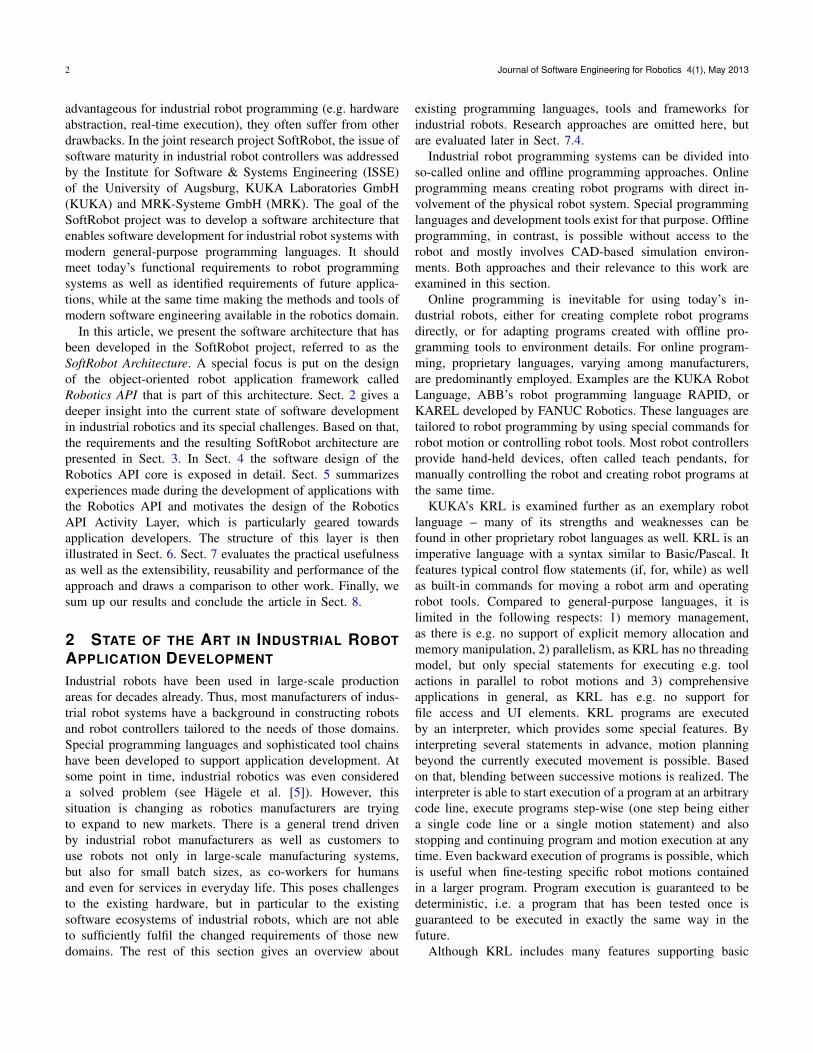
To achieve all the aforementioned goals, we developed a two-tier software architecture (introduced by Hoffmann et al. [13]),which is depicted in Fig. 1. Boxes inside the Robotics APIand RCC parts represent important concepts. Similar to UML,simple lines indicate associations between concepts and lineswith filled arrow indicate generalizations. Dotted lines betweenRobotics API and RCC concepts indicate that some conceptof the Robotics API is transformed to some other concept ofthe RCC during runtime.
The architecture’s most important aspect is the separationbetween the Robot Control Core tier and the Robotics API tier.The Robot Control Core (RCC) is responsible for real-timehardware control. It exhibits the Realtime Primitives Interface(RPI), described in previous work by Vistein et al. [14],that was designed to flexibly specify fine-grained real-timecritical commands. The Robotics API uses this interface fortasks that need to be executed deterministically and with real-time guarantees, like e.g. robot movements, and also providesmechanisms for the real-time critical combination of thosetasks by employing the flexibility of RPI. All such tasks andtask combinations are sent to the RCC for execution. Fromthe perspective of a Robotics API application, this executionis done atomically. The Robotics API is implemented in Java.
Robot Control Core Device
Drivers
Calculation
Modules
Command Layer
Activity Layer
Actuator
Ro
bo
tic
s A
PI
e
.g.
sta
nd
ard
Ja
va
RC
C
e.g
. C
++
Activity
PTP Robot
Action Command
Robot
Applications
Domain-Specific
Languages
Service-Oriented
Architectures
Actuator Interface Meta Data
Fig. 1. The SoftRobot architecture.
It is divided into two layers, called the Command Layer andthe Activity Layer. The following paragraphs take a closer lookat both tiers (as well as the layers of the Robotics API) andtheir roles considering the goals stated above. The detaileddesign of each Robotics API layer is presented in Sect. 4 andSect. 6.
3.1 Robot Control CoreThe Robot Control Core accepts commands specified in theRPI dataflow language, consisting of calculation modules withdefined input and output ports that may be interconnectedby typed dataflow links. Calculation modules may use devicedrivers to send data to or read data from devices. Commandsare specified as graphs of interconnected calculation mod-ules, thus they are also called RPI graphs. Such a graphis executed cyclically at a high rate (typically 1kHz). Thisexecution is performed deterministically by a real-time runtimeenvironment. In each execution cycle, the RPI graph is fullyevaluated. This dataflow-based approach is used to implementall functionality that is required by the higher levels. Forexample, the interpolation of pre-planned robot actions (likee.g. motions along defined cartesian paths), actions that arepartially or completely based on sensor measurements, andreactive behaviour (e.g. stopping a motion at the occurrenceof a certain event) are all encoded as RPI dataflow graphs. Inthis respect, the RCC does not offer a diverse set of differentoperations, but exposes only its capability to interpret RPIgraphs (and quickly switch from one graph to the next, seebelow). All high-level functionality that is explained in thiswork is achieved by encoding it appropriately as an RPIdataflow graph.
Within the SoftRobot project, a reference implementationof a Robot Control Core was created based on the Orocosframework [12]. We call this implementation SoftRobot RCC.It makes use of some scheduling features of Orocos pro-vided through TaskContexts as well as kinematic calculationfunctions provided by the KDL. However, the concept of a
A. Angerer et al./ Robotics API: Object-Oriented Software Development for Industrial Robots 5
Robot Control Core is not in any way bound to Orocos, thusother (hard real-time capable) frameworks or a pure C/C++implementation may be used.
On the RCC level, sensors can be integrated into commandsin arbitrary ways, as their measurement data is usually acces-sible via output ports of calculation modules. The real-timeexecution of the dataflow graphs can also be the basis forsynchronisation of multiple devices. The RCC furthermoresupports adding new device drivers and calculation modules(even at runtime). In sum, the Reqs. 1, 2 and 3 are consideredalready at the lowest architectural level. It turned out thatsupporting some of the special concepts of industrial robotcontrol (Req. 5) also requires support on the RCC level. Instan-taneous switching between the executed dataflow graphs (see aprevious paper of Vistein et al. [15]) can be used to realize e.g.motion blending. Sensor guided motions, in particular force-based manipulation, also profit from this concept. The Soft-Robot RCC was extended to support instantaneous commandswitching. Regarding Req. 4, the RCC tier is targeted at devicemanufacturers that need to develop and test new device driversand calculation modules for their hardware.
3.2 Robotics API Command LayerThe Robotics API Command Layer defines a model forspecifying operations that should be executed by devices, andfor defining combinations of such operations. The most basicway of defining an operation is employing a Command thattells an Actuator to execute a certain Action. Commands canbe composed to form more complex Command structures.Composition is based on an event mechanism, with eventsbeing provided by Actuators, Sensors and Actions, or Com-mands themselves (due to their life-cycle, e.g. Command hasended). This will be described in detail in Sect. 4. At thispoint, it is important to note that the Robotics API relieson the Robot Control Core for executing these operationswith real-time guarantees. The reference implementation ofthe Robotics API includes a generic and extensible algorithmfor transforming high-level concepts (Actions, Actuators andCommands, as well as all concepts regarding compositionof Commands) to the RPI language that is accepted by theSoftRobot RCC. Details about this algorithm are out of thescope of this work, but can be found in previous work ofSchierl et al. [16]. The concept of transforming complexRobotics API Commands, which contain continuous as well asdiscrete, event-based aspects, to an RPI dataflow graph is thekey to achieve the proposed abstraction for real-time mattersin the SoftRobot architecture. Besides specifying the structureof single complex Commands, the Robotics API also supportsdefining conditions at which it is possible to switch betweenseparate Robotics API Commands. Based on this, the RobotControl Core performs instantaneous switching from a runningRPI dataflow graph to its successor.
The requirements stated above are also reflected in thislayer. Due to the Command composition mechanisms, various
flavours of sensor-based operations are possible (Req. 1). Sen-sor guided motion is supported as well and is in general real-ized by concrete Action implementations. Considering Req. 2,the notion of multiple robots in one program is achievedby employing natural principles of object orientation, i.e.having multiple instances of the same class (e.g. Robot) andhaving different (sub-)classes for different real-world concepts(e.g. different Robot types). Coordination and synchronisationof multiple robots is supported by Command composition.By employing the Command switching mechanism describedabove, motion blending can be realized. Single-step executionof programs can be achieved using e.g. a debugger, as willbe detailed in the next section. In this way, the CommandLayer accounts for Req. 5. To support extensibility (Req. 3) theRobotics API as a whole employs a plug-in structure to supportnew types of Actions, Actuators and Sensors. The user groupsintended to work on this layer (Req. 4) are robot manufacturersas well as system integrators. Robot manufacturers mightextend this layer by introducing new Actuators and Actions ascounterparts to extensions to the RCC. System integrators mayimplement new Actions as well, or use the Command modelto implement complex operations as part of an application orto provide them to end users in a specialized API.
3.3 Robotics API Activity Layer
The Activity Layer in the Robotics API extends the CommandLayer and provides an easy-to-use programming interfaceto developers of robotics applications. While the CommandLayer is concerned about basic operations of devices (like arobot executing a linear motion) and very generic combinationmechanisms, the Activity Layer adds concepts frequently usedin application development, taking into consideration somerobotics-specific requirements. On this level, Actuators offera set of ActuatorInterfaces, each providing specific Activitiesthat the Actuator may execute. For instance, robots offer aLinInterface, providing Activities for different kinds of linearmotions (e.g. to absolute goals in space or to goals specifiedrelative to the current position). Activities are characterizedby a particularly designed asynchronous execution semantics,which will be described in detail later. This semantics allowsfor easily specifying continuous execution of real-time oper-ations on a programming language level. In addition, thereexist some predefined ways of combining Activities (e.g. forparallel or conditional execution). As all Activities and theircombinations are implemented on top of the Command Layermechanisms, the real-time properties are preserved.
Using the Activity Layer, defining sensor-based motionguards is still possible (Req. 1). However, flexibility is limitedin some respect, in favor of a slimmer API. Different kinds ofsensor guided motions are supported and realized by specialActivity implementations. Furthermore, special implementa-tions of ActuatorInterfaces and Activities provide support forparticular multi-robot operations like synchronized motions
6 Journal of Software Engineering for Robotics 4(1), May 2013
(Req. 2). Like Actuators and Actions, new ActuatorInterfacesand Activities may be added using the Robotics API’s plug-in mechanism to provide extensibility (Req. 3). Robot manu-facturers or system integrators might do this to provide newfunctionality to application developers (Req. 4). The ActivityLayer is particularly geared towards those developers andprovides them with an easy-to-use programming interface.
As mentioned above (Req. 5), developers of robotic ap-plications are used to some unique features of robot pro-gramming languages and their execution environments. TheActivity Layer therefore supports easy specification of contin-uous motion instructions, which is described in more detaillater. Single-step execution of (motion) instructions can beachieved by Java debugging. As to not confuse developersby stepping through internal operations of the Robotics API,the debugger can be configured appropriately. For example,the debugger of the Eclipse IDE provides the concept of stepfilters that control which methods or classes should not bestepped into during debugging. We are already working on anEclipse Plugin that supports application development with theRobotics API. This plugin can be easily extended to adequatelypre-configure the Eclipse debugger for robotic applications.However, developers have to take care if their program usesthe ability of the Robotics API to execute Commands orActivities asynchronously. This will decouple the RoboticsAPI program flow from the robot operations that have beentriggered. While the program flow may be paused by thedebugger, the robot operation that has been triggered beforewill not, which developers have to be aware of.
Considering direct selection of motion records, we didexperiments with extending Eclipse with a special programlauncher. It uses Java Reflection to allow developers to selectonly certain methods to be executed. While this is not asconvenient as e.g. KRLs ability to jump to single motionstatements, it can ease development and testing when theprogram is adequately structured. Backwards execution ofrobot programs is a feature that we did not tackle yet withour approach. Modifying the Java Virtual Machine to allowtrue backwards execution seems hard to realize. However, forpractical cases it might be helpful to extend at least someActivities by a kind of ”‘undo”’ functionality that e.g. couldbe used to drive backwards. Another possible approach is torecord motion interpolation and enable a reverse playback ofthe interpolated values. These approaches would at least easethe testing of series of subsequent motions. However, thisinability to completely match a domain specific language likeKRL has to be accepted as a limitation when using a general-purpose language.
The past sections illustrated the separation between thedifferent tiers and layers in the SoftRobot architecture anddefined the responsibilities of each part. The following sectionswill go into details about the design of the Robotics API tierwith its two layers.
r
TransactionCommand
RuntimeCommand
State
Command
WaitCommand
EventHandler
Action
EventEffect
Sensor
Actuator
provides
*
provides
*
influences
provides
*
consistsOf
*
attachedTo
*1
triggeredBy
1
provides*
executes
1
executes
1
targets
1
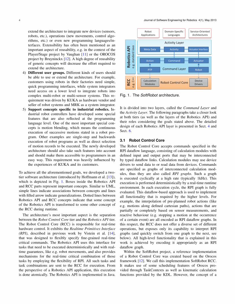
Fig. 2. Structure of the Robotics API Core, includingCommands and their composition
4 DESIGN OF THE ROBOTICS API CORE
The following sections will present the software design of theRobotics API core and the Command Layer in this core. Thedecisions that led to its design will be illustrated. The designof the Activity Layer is described separately in Sect. 6.
4.1 Actuators and Actions
Actuator (cf. Fig. 2, bottom left) can be considered one ofthe most basic classes in the Robotics API. An Actuator issome robotic device that is controllable by the application.Examples are single robot joints, complete robot arms, mobileplatforms or just field bus outputs of some robot controlsystem. Actuators have some properties (e.g. the number ofjoints of a robot) and can be configured in certain ways(e.g. defining the maximum allowed velocity of motions).Actuators in the Robotics API usually do not contain codethat implements the execution of any kind of operation (e.g.for interpolating motions of a robot arm). They can rather beseen as proxy objects representing devices controllable by theRobot Control Core. Instances of Actuators should not storeany state of the physical device they represent. Instead, theyusually retrieve their data by directly communicating with theRCC when necessary. This ensures that the data provided isalways up-to-date.
Control operations that Actuators should execute are mod-elled by the class Action (cf. Fig. 2, bottom left). Examplesfor concrete subclasses are LIN (linear motion of a roboticdevice in Cartesian space), SetValue (setting a value for a fieldbus output) or MoveTo (telling e.g. a robot base to move toa certain goal). Actions carry parameters that specify theirexecution more exactly (e.g. the velocity of a linear motion).Like Actuators, Actions as well do not contain code specifyinghow their execution is implemented exactly. Actions can ratherbe seen as a kind of token, semantically identifying a certain
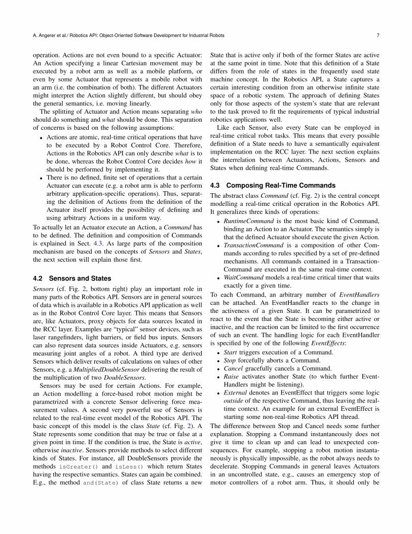
A. Angerer et al./ Robotics API: Object-Oriented Software Development for Industrial Robots 7
operation. Actions are not even bound to a specific Actuator:An Action specifying a linear Cartesian movement may beexecuted by a robot arm as well as a mobile platform, oreven by some Actuator that represents a mobile robot withan arm (i.e. the combination of both). The different Actuatorsmight interpret the Action slightly different, but should obeythe general semantics, i.e. moving linearly.
The splitting of Actuator and Action means separating whoshould do something and what should be done. This separationof concerns is based on the following assumptions:
• Actions are atomic, real-time critical operations that haveto be executed by a Robot Control Core. Therefore,Actions in the Robotics API can only describe what is tobe done, whereas the Robot Control Core decides how itshould be performed by implementing it.
• There is no defined, finite set of operations that a certainActuator can execute (e.g. a robot arm is able to performarbitrary application-specific operations). Thus, separat-ing the definition of Actions from the definition of theActuator itself provides the possibility of defining andusing arbitrary Actions in a uniform way.
To actually let an Actuator execute an Action, a Command hasto be defined. The definition and composition of Commandsis explained in Sect. 4.3. As large parts of the compositionmechanism are based on the concepts of Sensors and States,the next section will explain those first.
4.2 Sensors and StatesSensors (cf. Fig. 2, bottom right) play an important role inmany parts of the Robotics API. Sensors are in general sourcesof data which is available in a Robotics API application as wellas in the Robot Control Core layer. This means that Sensorsare, like Actuators, proxy objects for data sources located inthe RCC layer. Examples are “typical” sensor devices, such aslaser rangefinders, light barriers, or field bus inputs. Sensorscan also represent data sources inside Actuators, e.g. sensorsmeasuring joint angles of a robot. A third type are derivedSensors which deliver results of calculations on values of otherSensors, e.g. a MultipliedDoubleSensor delivering the result ofthe multiplication of two DoubleSensors.
Sensors may be used for certain Actions. For example,an Action modelling a force-based robot motion might beparametrized with a concrete Sensor delivering force mea-surement values. A second very powerful use of Sensors isrelated to the real-time event model of the Robotics API. Thebasic concept of this model is the class State (cf. Fig. 2). AState represents some condition that may be true or false at agiven point in time. If the condition is true, the State is active,otherwise inactive. Sensors provide methods to select differentkinds of States. For instance, all DoubleSensors provide themethods isGreater() and isLess() which return Stateshaving the respective semantics. States can again be combined.E.g., the method and(State) of class State returns a new
State that is active only if both of the former States are activeat the same point in time. Note that this definition of a Statediffers from the role of states in the frequently used statemachine concept. In the Robotics API, a State captures acertain interesting condition from an otherwise infinite statespace of a robotic system. The approach of defining Statesonly for those aspects of the system’s state that are relevantto the task proved to fit the requirements of typical industrialrobotics applications well.
Like each Sensor, also every State can be employed inreal-time critical robot tasks. This means that every possibledefinition of a State needs to have a semantically equivalentimplementation on the RCC layer. The next section explainsthe interrelation between Actuators, Actions, Sensors andStates when defining real-time Commands.
4.3 Composing Real-Time CommandsThe abstract class Command (cf. Fig. 2) is the central conceptmodelling a real-time critical operation in the Robotics API.It generalizes three kinds of operations:
• RuntimeCommand is the most basic kind of Command,binding an Action to an Actuator. The semantics simply isthat the defined Actuator should execute the given Action.
• TransactionCommand is a composition of other Com-mands according to rules specified by a set of pre-definedmechanisms. All commands contained in a Transaction-Command are executed in the same real-time context.
• WaitCommand models a real-time critical timer that waitsexactly for a given time.
To each Command, an arbitrary number of EventHandlerscan be attached. An EventHandler reacts to the change inthe activeness of a given State. It can be parametrized toreact to the event that the State is becoming either active orinactive, and the reaction can be limited to the first occurrenceof such an event. The handling logic for each EventHandleris specified by one of the following EventEffects:
• Start triggers execution of a Command.• Stop forcefully aborts a Command.• Cancel gracefully cancels a Command.• Raise activates another State (to which further Event-
Handlers might be listening).• External denotes an EventEffect that triggers some logic
outside of the respective Command, thus leaving the real-time context. An example for an external EventEffect isstarting some non-real-time Robotics API thread.
The difference between Stop and Cancel needs some furtherexplanation. Stopping a Command instantaneously does notgive it time to clean up and can lead to unexpected con-sequences. For example, stopping a robot motion instanta-neously is physically impossible, as the robot always needs todecelerate. Stopping Commands in general leaves Actuatorsin an uncontrolled state, e.g., causes an emergency stop ofmotor controllers of a robot arm. Thus, it should only be
8 Journal of Software Engineering for Robotics 4(1), May 2013
used in extreme cases. Instead, Cancel is preferred to givethe cancelled Command the opportunity to terminate in acontrolled way. For example, in case of a robot motion,Cancel should brake the robot until halt, and then terminatethe command. When a TransactionCommand is cancelled, itsconcrete definition decides how to handle the Cancel request(e.g., forwarding it to all or only some of its inner Commands).In contrast, stopping a TransactionCommand always stops allinner Commands immediately.
Some additional rules constrain the use of certain Event-Effects: Start may only be used to start another Commandinside the same TransactionCommand. So Start cannot be usedat all in RuntimeCommands. Stop and Cancel may targetthe Command itself or one of the inner Commands of aTransactionCommand. These rules are enforced at runtime.
Sensors have been identified as possible providers of Statesin Sect. 4.2. However, States can also be provided by Actions,Actuators and Commands. Action States describe e.g. certainprogress or error conditions of an action. Examples are Statestelling that a certain via-point of a trajectory has been passed,or that the Action has started or completed execution. ActuatorStates include certain error states of the Actuator (e.g. that aset-point commanded by the Action is invalid or that an emer-gency stop has occurred), and a completion state (wheneverthe Actuator has reached its latest set-point). Command Statescover the life-cycle of each Commands by e.g. indicating thatit has been started, stopped or cancelled.
Through the mechanisms presented above, the RoboticsAPI’s Command model allows the specification of arbitrarilycomplex operations. However, those operations have to befinite, i.e. can not contain loops. In particular, it is not allowedto re-start Commands that have already been executed. Thus,complex control flow involving looping has to be realized inRobotics API applications, using (non-real-time) mechanismsof the programming language. This decision led to less prob-lems in the algorithm transforming Commands to RPI graphs.Up to now, no practical limitations arose due to this. Weare, however, investigating means of relaxing or dropping thisrestriction.
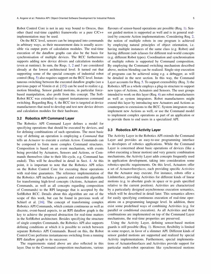
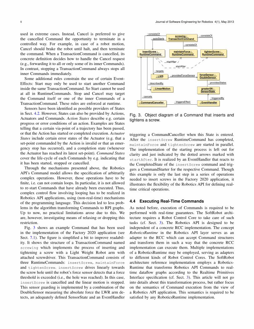
Fig. 3 shows an example Command that has been usedin the implementation of the Factory 2020 application (seeSect. 7.1). The figure is simplified a bit to improve readabil-ity. It shows the structure of a TransactionCommand namedscrewing which implements the process of inserting andtightening a screw with a Light Weight Robot arm withattached screwdriver. This TransactionCommand consists ofthree RuntimeCommands: insertScrew, maintainForce
and tightenScrew. insertScrew drives linearly towardsthe screw hole until the robot’s force sensor detects that a forcethreshold is exceeded (i.e., the hole was reached). In this case,insertScrew is cancelled and the linear motion is stopped.This sensor guarding is implemented by a combination of theDoubleSensor measuring the absolute force the LWR arm de-tects, an adequately defined SensorState and an EventHandler
screwing : TransactionCommand
: CommandCanceller
insertScrew : RuntimeCommand
maintainForce : RuntimeCommand
tightenScrew : RuntimeCommand
: LinearMotion
: EventHandler
greater5N : SensorState
forceSensor : DoubleSensor
: LWR
startAfter
: cancels
: describedBy
: triggersEffect
: providesForceSensor
startAfter
: consistsOf
: targets
: consistsOf
: autoStarts
: consistsOf
: triggeredBy
: providesStates
Fig. 3. Object diagram of a Command that inserts andtightens a screw.
triggering a CommandCanceller when this State is entered.After the insertScrew RuntimeCommand has completed,maintainForce and tightenScrew are started in parallel.The implementation of the starting process is left out forclarity and just indicated by the dotted arrows marked withstartAfter. It is realized by an EventHandler that reacts tothe CompletedState of the insertScrew command and trig-gers a CommandStarter for the respective Command. Thoughthis example is only the last step in a series of operationsneeded to insert screws in the Factory 2020 application, itillustrates the flexibility of the Robotics API for defining real-time critical operations.
4.4 Executing Real-Time Commands
As noted before, execution of Commands is required to beperformed with real-time guarantees. The SoftRobot archi-tecture requires a Robot Control Core to take care of suchtasks (cf. Sect. 3). The Robotics API is designed to beindependent of a concrete RCC implementation. The conceptRoboticsRuntime in the Robotics API layer serves as anadapter to the RCC which can accept Command structuresand transform them in such a way that the concrete RCCimplementation can execute them. Multiple implementationsof a RoboticsRuntime may be employed, serving as adaptersto different kinds of Robot Control Cores. The SoftRobotarchitecture reference implementation employs a Robotics-Runtime that transforms Robotics API Commands to real-time dataflow graphs according to the Realtime PrimitivesInterface specification (cf. Sect. 3). This article will not gointo details about this transformation process, but rather focuson the semantics of Command execution from the view ofa Robotics API application. This semantics is required to besatisfied by any RoboticsRuntime implementation.
A. Angerer et al./ Robotics API: Object-Oriented Software Development for Industrial Robots 9
+load(Command) : CommandHandle
RoboticsRuntime
+start()+scheduleAfter(CommandHandle)+cancel()+abort()+waitComplete()
CommandHandle
+start() : CommandHandle
Command
SoftRobotRuntime SoftRobotRCC
Actuator
«use»
loadsCommandsTo
controlledBy
1
*
-executedBy
1
1
0..1
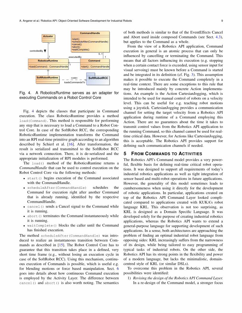
Fig. 4. A RoboticsRuntime serves as an adapter forexecuting Commands on a Robot Control Core
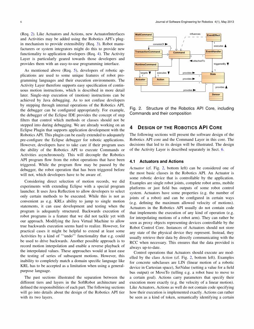
Fig. 4 depicts the classes that participate in Commandexecution. The class RoboticsRuntime provides a methodload(Command). This method is responsible for performingany step that is necessary to load a Command to a Robot Con-trol Core. In case of the SoftRobot RCC, the correspondingRoboticsRuntime implementation transforms the Commandinto an RPI real-time primitive graph according to an algorithmdescribed by Schierl et al. [16]. After transformation, theresult is serialized and transmitted to the SoftRobot RCCvia a network connection. There, it is de-serialized and theappropriate initialization of RPI modules is performed.
The load() method of the RoboticsRuntime returns aCommandHandle that can be used to control execution on theRobot Control Core via the following methods:
• start() begins execution of the Command associatedwith the CommandHandle.
• scheduleAfter(CommandHandle) schedules theCommand for execution right after another Commandthat is already running, identified by the respectiveCommandHandle.
• cancel() sends a Cancel signal to the Command whileit is running.
• abort() terminates the Command instantaneously whileit is running.
• waitComplete() blocks the caller until the Commandhas finished execution.
The method scheduleAfter(CommandHandle) was intro-duced to realize an instantaneous transition between Com-mands as described in [15]. The Robot Control Core has toguarantee that this transition takes place in a defined, veryshort time frame (e.g., without losing an execution cycle incase of the SoftRobot RCC). Using this mechanism, continu-ous execution of Commands is possible, which is useful e.g.for blending motions or force based manipulation. Sect. 6goes into details about how continuous Command executionis employed by the Activity Layer. The difference betweencancel() and abort() is also worth noting. The semantics
of both methods is similar to that of the EventEffects Canceland Abort used inside composed Commands (see Sect. 4.3),but applies to the Command as a whole.
From the view of a Robotics API application, Commandexecution in general is an atomic process that can only beinfluenced by cancelling or terminating the Command. Thismeans that all factors influencing its execution (e.g. stoppingwhen a certain contact force is exceeded, using sensor input forvisual servoing) must be known before a Command is startedand be integrated in its definition (cf. Fig. 3). This assumptionmakes it possible to execute the Command completely in areal-time context. There are some exceptions to this rule thatmay be introduced mainly by concrete Action implementa-tions. An example is the Action CartesianJogging, which isintended to be used for manual control of robots on a velocitylevel. This can be useful for e.g. teaching robot motionsusing a joystick. CartesianJogging provides a communicationchannel for setting the target velocity from a Robotics APIapplication during runtime of a Command employing thisAction. There are no guarantees about the time it takes totransmit control values from the Robotics API application tothe running Command, so this channel cannot be used for real-time critical data. However, for Actions like CartesianJogging,this is acceptable. The Robotics API provides support fordefining such communication channels if needed.
5 FROM COMMANDS TO ACTIVITIESThe Robotics API’s Command model provides a very power-ful, flexible basis for defining real-time critical robot opera-tions. It was designed to support all requirements of today’sindustrial robotics applications as well as tight integration ofsensor based and multi-robot operations in future applications.However, the generality of this model sometimes leads tocumbersomeness when using it directly for the developmentof robotic applications. In particular, applications created ontop of the Robotics API Command Layer looked compli-cated compared to applications created with KUKA’s robotlanguage KRL. This observation is not too surprising, asKRL is designed as a Domain Specific Language. It wasdeveloped solely for the purpose of creating industrial roboticsapplications, whereas the Robotics API wants to extend ageneral-purpose language for supporting development of suchapplications. In a sense, both architectures are approaching theproblem of finding an optimal industrial robot language fromopposing sides: KRL increasingly suffers from the narrownessof its design, while being tailored to easy programming oftypical tasks of industrial robots. On the other side, theRobotics API has its strong points in the flexibility and powerof a modern language, but lacks the minimalistic, domain-centred style of KRL (or similar DSLs).
To overcome this problem in the Robotics API, severalpossibilities were identified:
1) Revising the design of the Robotics API Command Layer.In a re-design of the Command model, a stronger focus
10 Journal of Software Engineering for Robotics 4(1), May 2013
could be put on the interface to application developers,reducing its complexity.
2) Introducing an application development layer on topof the Command Layer. A separate layer on top ofthe Robotics API Command layer could be designedto introduce an interface more focused on the needs ofrobotics application developers.
3) Creating a Domain Specific Language on top of theRobotics API. There are several powerful tools andframeworks for creating DSLs on top of modern pro-gramming languages. Using those tools, developing aDSL for industrial robotics should be possible withmoderate effort.
The first of those approaches has the advantage of stayingwithin one single layer in the Robotics API. No separatelayer on top of the Robotics API core would have to beintroduced, adding no additional complexity to the design.However, the following considerations led to a decision againstthis solution. The current design of the Robotics API core andits Command Layer proved to be a stable and flexible platformfor specifying Commands that can be used as a description ofreal-time critical operations to be executed by a Robot ControlCore. This in itself defines a clear scope of responsibility.Following the principle of Separation of Concerns (attributedto Dijkstra [17]), it seemed logical to choose one of the lattersolutions. Additionally, all stated requirements like multi-robotcoordination and sensor integration could be fulfilled by thecurrent Command Layer design. Changing this design accord-ing to completely different requirements like a minimalisticprogramming interface bears the danger of sacrificing someof the other requirements.
This led to the decision to establish a separate interface,being easy to use and particularly tailored to the needs of appli-cation developers. The introduction of a DSL seemed like theultimate way of tailoring such an interface to the requirements.However, one of the strong points of the Robotics API is theJava ecosystem with its many libraries for different purposes.This was identified to be useful also for the developmentof robotics applications, e.g. for integrating computer visionalgorithms or developing intuitive human-robot interfaces. Theuse of a DSL for developing robot applications would arisethe question of interoperability with Java.
To stay in the Java ecosystem, we decided to introduce aseparate Java-based layer on top of the Robotics API. Thislayer should provide an abstraction of the Robotics API Com-mand model that reflects the mechanisms useful for roboticsdevelopers. In particular, features like motion blending shouldbe easily usable by providing appropriate API options. Thenext section presents the design of the Activity Layer inthe Robotics API. The Command Layer is not coupled tothe Activity Layer, thus the Robotics API may still be usedwithout the Activity Layer extension. The Activity Layer canbe considered one of possibly several kinds of interfacesoffered in the future towards application developers.
6 MODELING OPERATIONS BY ACTIVITIESThe separation of Action and Actuator in the Robotics APICommand Layer is a very flexible mechanism (cf. 4.1), butat the same time a source of complexity when implementingrobot operations. Instead of writing something like
robot.lin(goal);
for letting a robot execute a linear motion to a given goal,developers have to write
robot.getRuntime().createRuntimeCommand(robot,new Lin(start, goal)).execute();
using the Robotics API Command Layer. The additionalcomplexity is caused on the one hand by the need to createa RuntimeCommand for defining Actuator and Action tobe executed. On the other hand, Actions often need manyparameters for fully specifying them. In this case, the LinAction requires a start point of the motion to be specifiedin addition to its goal point. Intuitively, the current positionof the robot at the time the motion command is issued couldimplicitly be taken as start position. This would enable a morecompact specification of the Lin Action like presented in thefirst code snippet above. However, any RuntimeCommand canbe used arbitrarily inside larger TransactionCommands. Whena TransactionCommand is processed in the RoboticsRuntime,the full specification of all Actions is already required. In theLin example, information about the start and goal position of amotion is needed to calculate a correct trajectory, which is theninterpolated with real-time constraints by the Robot ControlCore. Determining the robot’s current position at the point intime that the RuntimeCommand containing the Lin Action isactually executed is in general not possible. It depends largelyon the Commands in the TransactionCommand that are to beexecuted before the current RuntimeCommand, which mightalso move the robot.
Another frequently used feature in industrial robot pro-gramming is continuous execution of motions with blend-ing between single motion instructions. In commercial robotlanguages like KRL, this feature is enabled by just addinga special keyword to the motion instruction that may beblended over to a subsequent motion. The Robotics APICommand Layer supports motion blending between successiveCommands as well, backed by RPI’s instantaneous switchingmechanism (cf. Sect. 3.1 and [15]). However, specifying ap-propriate Robotics API motion Commands that handle correctblending in between them is quite complex. Thus, applicationdevelopers should not have to do that themselves.
A reduction of this kind of complexity on API level isachieved by two different mechanisms. The first one is theintroduction of the concept Activity, which is presented inSect. 6.1. The second one involves creating Activities withthe help of ActuatorInterfaces, introduced in Sect. 6.3. Bycombining these two concepts, the resulting Activity Layeroffers a special interface to developers, which is illustrated
A. Angerer et al./ Robotics API: Object-Oriented Software Development for Industrial Robots 11
with several examples. The Activity Layer also provides a setof predefined mechanisms for composing Activities. Sect. 6.2gives an overview of this.
6.1 Specification and Execution of ActivitiesAn Activity is defined as a real-time critical operation, af-fecting one or more Actuators, that supplies meta data aboutthe state of each Actuator during or after the execution ofthe operation. The real-time critical execution logic of anActivity is implemented by a Command. The execution ofActivities is controlled by an ActivityScheduler. This scheduleris a singleton object, meaning that there exists exactly oneglobal instance of it in each Robotics API application.
Activities expose among others the public methodsexecute() and beginExecute(). The former starts exe-cution of the operation modelled by the Activity and blocksthe calling thread until execution fully completes. The lattermethod also starts execution, but returns control to the callingthread once the operation is actually started (i.e. the respectiveCommand has been started on the Robot Control Core). Thisasynchronous execution gives the caller the possibility to startexecution of a second Activity shortly after an Activity hasbeen started.
The execution of each Activity is controlled internallyby the ActivityScheduler. Therefore, the implementationsof Activity#execute() and Activity#beginExecute()
submit the Activity for execution to the ActivitySchedulerby calling appropriate methods. The ActivityScheduler stores,for each Actuator, the last Activity that has been startedand affected this Actuator. Thus, when a new Activity is tobe scheduled, the ActivityScheduler can supply all relevantpreceding Activities to the new Activity. Note that there mightbe multiple (or no) preceding Activities, as multiple Actuatorsaffected by the new Activity might have executed differentActivities before. The new Activity can inspect the precedingActivities and their meta-data and can extract informationneeded for its own execution. For example, a motion Activitya is interested in the Actuator’s state during the executionof a preceding motion p. If p is already completed at thetime of a’s start, a might take the robot’s current positionas its starting point. The same applies if there is no Activitypreceding a (e.g. after program startup). If p is still running,a might inspect meta data provided by p about the robot’smotion (position, velocity, acceleration, ...) at some futurepoint in time where the motion executed by p should beblended into the motion executed by a. If a can extract allnecessary information, it can signal the ActivityScheduler thatit is able to take over the running Activity p. In this case, theActivityScheduler will perform a scheduling of the Commandprovided by a. To achieve that, it calls the Command’s methodscheduleAfter(CommandHandle) to let the RoboticsRun-time perform instantaneous switching between the currentlyrunning Command (provided by p, identified by its respectiveCommandHandle) and the new Command (cf. Sect. 4.4).
In detail, the ActivityScheduler distinguishes three caseswhen a new Activity a is to be scheduled:
1) If all Actuators affected by a did not execute anyActivity before, a is started.
2) Otherwise, if, for at least one Actuator affected by a,another Activity p is already running and an Activitys is already scheduled after p for the same Actua-tor, scheduling of a is rejected. This implies that theActivityScheduler can only schedule one Activity at atime.
3) Otherwise, the following steps are performed:a) Determine the Activities P previously executed for
all Actuators affected by a. Thus, P contains atmost one Activity for each of these Actuators.
b) Wait until at most one Activity p of the ActivitiesP is still running.
c) Let a determine all Actuators Ψ that it is able totake control of.
d) If Ψ is a superset of all Actuators controlled by p,schedule a’s Command after p’s Command.
e) Otherwise, await end of execution of p’s Com-mand, then start a’s Command.
The restriction to keep only one Activity running beforescheduling a new Activity (step 3b) had to be introduced dueto the fact that RPI currently only allows a Command to bescheduled after exactly one predecessor. There is, however,work in progress to release this restriction.
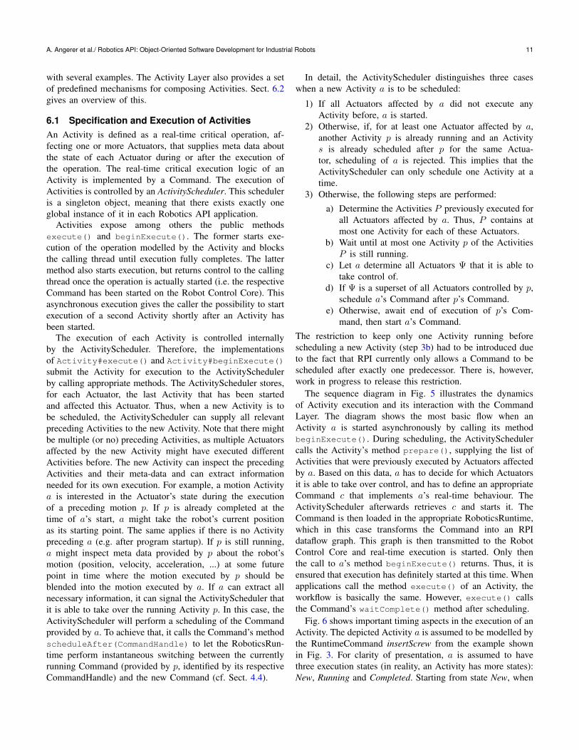
The sequence diagram in Fig. 5 illustrates the dynamicsof Activity execution and its interaction with the CommandLayer. The diagram shows the most basic flow when anActivity a is started asynchronously by calling its methodbeginExecute(). During scheduling, the ActivitySchedulercalls the Activity’s method prepare(), supplying the list ofActivities that were previously executed by Actuators affectedby a. Based on this data, a has to decide for which Actuatorsit is able to take over control, and has to define an appropriateCommand c that implements a’s real-time behaviour. TheActivityScheduler afterwards retrieves c and starts it. TheCommand is then loaded in the appropriate RoboticsRuntime,which in this case transforms the Command into an RPIdataflow graph. This graph is then transmitted to the RobotControl Core and real-time execution is started. Only thenthe call to a’s method beginExecute() returns. Thus, it isensured that execution has definitely started at this time. Whenapplications call the method execute() of an Activity, theworkflow is basically the same. However, execute() callsthe Command’s waitComplete() method after scheduling.
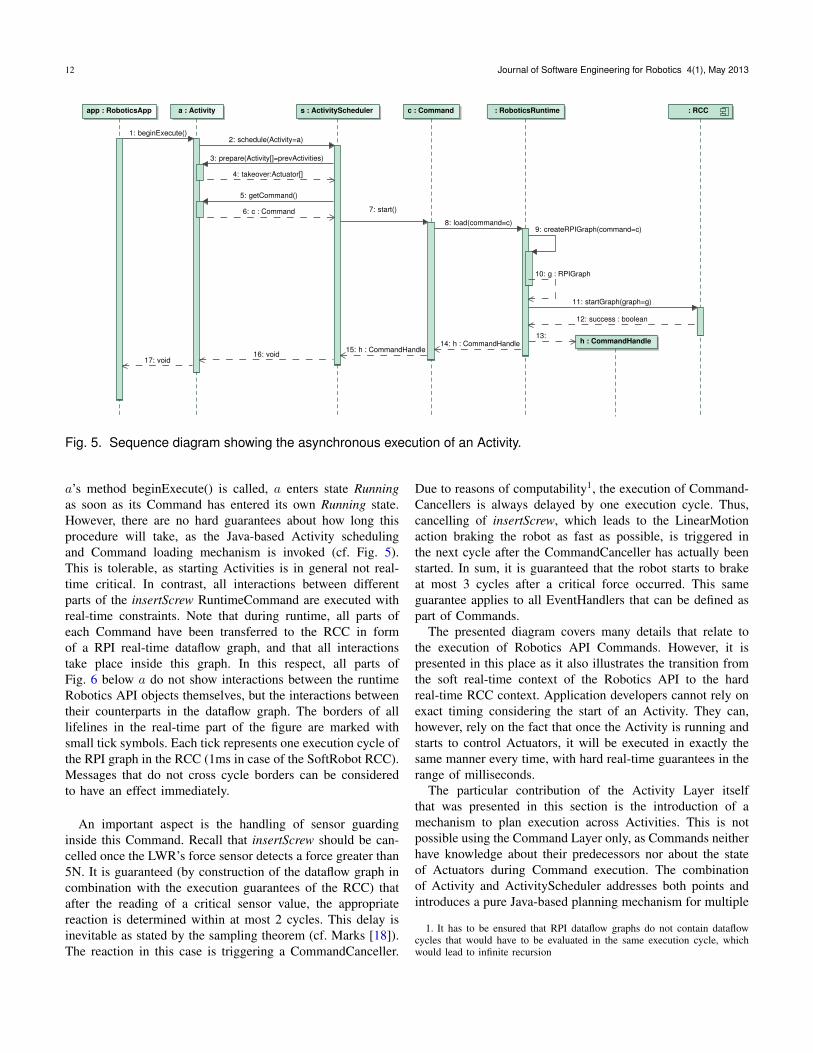
Fig. 6 shows important timing aspects in the execution of anActivity. The depicted Activity a is assumed to be modelled bythe RuntimeCommand insertScrew from the example shownin Fig. 3. For clarity of presentation, a is assumed to havethree execution states (in reality, an Activity has more states):New, Running and Completed. Starting from state New, when
12 Journal of Software Engineering for Robotics 4(1), May 2013
s : ActivityScheduler
h : CommandHandle
: RoboticsRuntimeapp : RoboticsApp : RCCc : Commanda : Activity
getCommand()5:
start()7:
void16:
prepare(Activity[]=prevActivities)3:
createRPIGraph(command=c)9:
g : RPIGraph10:
startGraph(graph=g)11:
13: h : CommandHandle14:
beginExecute()1:
success : boolean12:
load(command=c)8:
h : CommandHandle15:
schedule(Activity=a)2:
void17:
takeover:Actuator[]4:
c : Command6:
Fig. 5. Sequence diagram showing the asynchronous execution of an Activity.
a’s method beginExecute() is called, a enters state Runningas soon as its Command has entered its own Running state.However, there are no hard guarantees about how long thisprocedure will take, as the Java-based Activity schedulingand Command loading mechanism is invoked (cf. Fig. 5).This is tolerable, as starting Activities is in general not real-time critical. In contrast, all interactions between differentparts of the insertScrew RuntimeCommand are executed withreal-time constraints. Note that during runtime, all parts ofeach Command have been transferred to the RCC in formof a RPI real-time dataflow graph, and that all interactionstake place inside this graph. In this respect, all parts ofFig. 6 below a do not show interactions between the runtimeRobotics API objects themselves, but the interactions betweentheir counterparts in the dataflow graph. The borders of alllifelines in the real-time part of the figure are marked withsmall tick symbols. Each tick represents one execution cycle ofthe RPI graph in the RCC (1ms in case of the SoftRobot RCC).Messages that do not cross cycle borders can be consideredto have an effect immediately.
An important aspect is the handling of sensor guardinginside this Command. Recall that insertScrew should be can-celled once the LWR’s force sensor detects a force greater than5N. It is guaranteed (by construction of the dataflow graph incombination with the execution guarantees of the RCC) thatafter the reading of a critical sensor value, the appropriatereaction is determined within at most 2 cycles. This delay isinevitable as stated by the sampling theorem (cf. Marks [18]).The reaction in this case is triggering a CommandCanceller.
Due to reasons of computability1, the execution of Command-Cancellers is always delayed by one execution cycle. Thus,cancelling of insertScrew, which leads to the LinearMotionaction braking the robot as fast as possible, is triggered inthe next cycle after the CommandCanceller has actually beenstarted. In sum, it is guaranteed that the robot starts to brakeat most 3 cycles after a critical force occurred. This sameguarantee applies to all EventHandlers that can be defined aspart of Commands.
The presented diagram covers many details that relate tothe execution of Robotics API Commands. However, it ispresented in this place as it also illustrates the transition fromthe soft real-time context of the Robotics API to the hardreal-time RCC context. Application developers cannot rely onexact timing considering the start of an Activity. They can,however, rely on the fact that once the Activity is running andstarts to control Actuators, it will be executed in exactly thesame manner every time, with hard real-time guarantees in therange of milliseconds.
The particular contribution of the Activity Layer itselfthat was presented in this section is the introduction of amechanism to plan execution across Activities. This is notpossible using the Command Layer only, as Commands neitherhave knowledge about their predecessors nor about the stateof Actuators during Command execution. The combinationof Activity and ActivityScheduler addresses both points andintroduces a pure Java-based planning mechanism for multiple
1. It has to be ensured that RPI dataflow graphs do not contain dataflowcycles that would have to be evaluated in the same execution cycle, whichwould lead to infinite recursion
A. Angerer et al./ Robotics API: Object-Oriented Software Development for Industrial Robots 13
insert-
Screw
: Runtime-
Command
New
Cancelling
Terminated
Running
: Linear-
MotionRunning
Braking
Completed
New
forceSensor
: DoubleSensor < 5N >= 5N
greater5N
: SensorStatenot active
active
: EventHandlerIdle
Executing
: Command-
Canceller
Idle
Executing
a : Activity
New
Running
Completed
{2}
{?}{?}
{1}
started
start
start
cancel
valueChanged
cancel
active
execute
completed
completed
RA
PI
So
ftR
ob
ot
RC
C
Fig. 6. UML timing diagram of Activity execution. Irrele-vant parts of execution have been omitted, indicated by di-agonal line pairs on lifelines. Tick symbols indicate cyclicexecution of a lifeline. Important timing constraints areannotated, where ’?’ indicates that no timing guaranteescan be given at all.
successive operations. For application developers, this resultsin a very easy way of activating motion blending by justexecuting Activities asynchronously. However, blending be-tween subsequent motions is only one example of establishingan Activity-specific execution semantics using asynchronousexecution. Other possible use cases include e.g. force-basedmanipulation or in general Activities that employ differentkinds of control algorithms. In a scenario where Activities letActuators apply defined forces to the environment, subsequentActivities may have to be aware of this situation and cope withit to ensure stability of the system.
Note that developers have the choice to perform single-step execution of Activities by using the synchronous methodexecute() at any point in their programs. Also note that,considering timing guarantees, this is only a best-effort ap-proach. There is no guarantee that Activity scheduling willbe fast enough to schedule the respective Commands before apreceding Command has reached a certain execution state. Inthe case of motion blending, the implementations of motionActivities then discard blending over the preceding Activity.Instead, the preceding motion is executed to its natural endand the following motion starts from there. With motionblending being an optimization technique in robot programs,
this behaviour is acceptable if it happens only in few cases.However, application developers as well as developers of newkinds of Activities have to be aware of it.
6.2 Composing ActivitiesOne of the strongest features of the Command Layer is thepossibility to compose Commands using a flexible event-based mechanism and to execute such composed Commandson the Robot Control Core with real-time guarantees. Im-plementations of different Activities employ this mechanismto provide more complex functionality out-of-the-box to pro-grammers. For instance, implementations of Light WeightRobot Actuators support performing a certain motion until acontact force is measured and then switch to a mode wherethe force is maintained. The respective ActuatorInterfacesfor Light Weight Robots in the Robotics API realize thisas a sequential composition of single Activities (motion andmaintaining force, where the first one is additionally sensor-guarded). Furthermore, all implementations of motion Activi-ties contain different execution paths to handle the cases thata motion blends over a preceding motion or that the motionis executed from its original start point. This is realized byparallel composition of several Activities that are executed ina mutually exclusive manner.
The Activity Layer also allows the composition of anyActivities to more complex Activity structures with a definedexecution semantics. In contrast to the Command compositionmechanism, the flexibility is reduced a bit. Instead, templatesfor recurring composition patterns are provided. This againis in many ways inspired by features provided by today’sspecialized robot programming languages. Other patterns wereidentified during development of application prototypes inthe SoftRobot project. Currently the following compositionpatterns of Activities are provided:
• Sequential composition. The specified Activities are exe-cuted one after another (optionally with blending).
• Parallel composition. The specified Activities are startedat the same time and run in parallel.
• Conditional execution. Based on a given condition, eitherone or another Activity is started.
• Composition of main task and subtasks. One or moreActivities are started at defined conditions during theexecution of a main Activity.
Sequential composition proved to be useful e.g. for robotgrippers that need a sequence of field bus outputs to be set inorder to control operation. Parallel composition was employedfor instance to realize synchronized motion of multiple robotarms. Conditional execution is useful e.g. for deciding whichoperation to execute next based on measurements of sensors.By composing sub tasks with a main task, tool actions maybe executed at defined points of a robot motion.
Note that composing Activities creates new Activities,which may again be composed to arbitrarily complex struc-tures. Each type of composed Activity creates a Robotics API
14 Journal of Software Engineering for Robotics 4(1), May 2013
Command that combines all Commands created by the innerActivities, plus appropriate EventHandlers so that the be-haviour of the resulting Command complies to the semanticsof the composed Activity. When composing Activities, it is notpossible to create a loop by e.g. re-starting an Activity that hasalready been executed. This limitation is caused by the designof the Command model (cf. Sect. 4.3), which Activities useto implement their functionality. However, the compositionmechanisms for Activities combine the meta-data of innerActivities as well, such that scheduling of a composed Activitycan be performed appropriately. Thus, also infinite sequencesof complex Activities can be scheduled (on a best-effort basis,as mentioned above) which will result in continuous operationif feasible. For instance, blending across a (infinite) seriesof motion Activities of multiple synchronized robot arms ispossible.
6.3 Binding Functionality to Actuators
For application developers, an important point is the cre-ation of concrete Activities for a specific Actuator. In theRobotics API Command Layer, Actuators and Actions arenot coupled at all. The reasons for this design are explainedin Sect. 4.1. This missing coupling was identified to be adifficulty considering usability by developers. They cannotidentify on an API level which Actions are usable for whichActuators. Even worse, the validity of an Action for use with acertain Actuator can only be checked at runtime in a late phaseof Command processing and can thus lead to complicatedruntime exceptions that must be interpreted by developers.
To mitigate this issue, the concept ActuatorInterface wasintroduced. ActuatorInterfaces combine a set of related func-tionalities of Actuators and expose them to application devel-opers. ActuatorInterface is intended to be subclassed to formmore concrete ActuatorInterfaces. For example, all Robots inthe Activity Layer provide amongst others a LinInterface and aPtpInterface. The former provides methods to execute differentkinds of linear Cartesian motions (e.g. to absolute or relativegoals), the latter is similar but covers point-to-point motions injoint space. By that mechanism, functionality is semanticallygrouped. Additionally, developers can query Actuators directlyabout the ActuatorInterfaces they support. Thus, they get directand clear feedback whether a given Actuator is able to performcertain kinds of operations.
The best imaginable solution for realizing the ActuatorIn-terface concept would be to provide developers with staticallytyped extension of the respective Actuators. However, dueto the characteristics of Java (single inheritance, no mixinmechanism, no extension methods like in C# etc.), exten-sible functional composition could only be realized usingan aggregation mechanism. Thus the definition of the classActuator was revised such that it became an aggregationof ActuatorInterfaces. This actually required a modificationon the Robotics API Core/Command Layer. However, as
the basic ActuatorInterface is very slim and generic, thisextension did not introduce further coupling, in particular notto the Activity Layer itself. The Activity Layer instead relieson the ActuatorInterface concept and uses it as a basis forgrouping Activities and relating them to Actuators. ConcreteActuatorInterface implementations like the aforementionedLinInterface and PtpInterface expose methods that create andreturn Activity implementations.
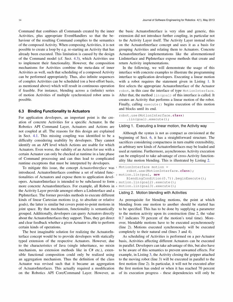
In the following, we will demonstrate the usage of thisinterface with concrete examples to illustrate the programminginterface to application developers. Executing a linear motionwith a robot requires the statement given in Listing 1. Itfirst selects the appropriate ActuatorInterface of the Actuatorrobot, in this case the interface of type MotionInterface.After that, the method lin(goal) of this interface is called. Itcreates an Activity that performs a linear motion of the robot.Finally, calling execute() begins execution of this motionand blocks until its end.
robot.use(MotionInterface. c l a s s).lin(goal).execute();
Listing 1. Executing a linear motion, the Activity way
Although the syntax is not as compact as envisioned at thebeginning of Sect. 6, it has a straightforward structure. Thesacrifices considering compactness in turn enable extensibility,as arbitrary new kinds of ActuatorInterfaces may be loaded andused at runtime. Furthermore, asynchronous Activity executioncan be employed to take advantage of cross-Activity function-ality like motion blending. This is illustrated by Listing 2.
1 MotionInterface motion =robot.use(MotionInterface. c l a s s);
2 motion.lin(goal, newBlendingCondition(0.7)).beginExecute();
3 motion.lin(goal2).execute();4 motion.lin(goal3).execute();
Listing 2. Motion blending with Activities
As prerequisite for blending motions, the point at whichblending from one motion to another should be started hasto be specified. This has to be done by supplying a parameterto the motion activity upon its construction (line 2, the value0.7 indicates 70 percent of the motion’s total time). More-over, blendable motions have to be executed asynchronously(line 2). Motions executed synchronously will be executedcompletely to their natural end (lines 3 and 4).
As scheduling of Activities is performed on a per-Actuatorbasis, Activities affecting different Actuators can be executedin parallel. Developers can take advantage of this, but also haveto be aware of this semantics to prevent unwanted effects. Forexample, in Listing 3, the Activity closing the gripper attachedto the moving robot (line 3) will be executed in parallel to thefirst motion (line 2). In particular, it will not be executed afterthe first motion has ended or when it has reached 70 percentof its execution progress - these dependencies will only be
A. Angerer et al./ Robotics API: Object-Oriented Software Development for Industrial Robots 15
respected by Activities affecting the same Actuator (line 4),in this case the robot.
1 MotionInterface motion =robot.use(MotionInterface. c l a s s);
2 motion.lin(goal, newBlendingCondition(0.7)).beginExecute();
3 gripper.use(GrippingInterface. c l a s s).close().beginExecute();
4 motion.lin(goal2).execute();
Listing 3. Asynchronous parallel execution of Activities
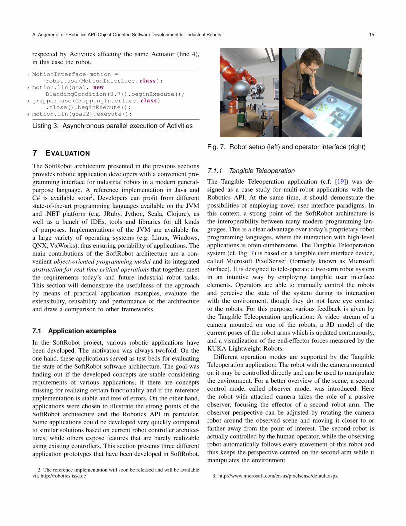
7 EVALUATION
The SoftRobot architecture presented in the previous sectionsprovides robotic application developers with a convenient pro-gramming interface for industrial robots in a modern general-purpose language. A reference implementation in Java andC# is available soon2. Developers can profit from differentstate-of-the-art programming languages available on the JVMand .NET platform (e.g. JRuby, Jython, Scala, Clojure), aswell as a bunch of IDEs, tools and libraries for all kindsof purposes. Implementations of the JVM are available fora large variety of operating systems (e.g. Linux, Windows,QNX, VxWorks), thus ensuring portability of applications. Themain contributions of the SoftRobot architecture are a con-venient object-oriented programming model and its integratedabstraction for real-time critical operations that together meetthe requirements today’s and future industrial robot tasks.This section will demonstrate the usefulness of the approachby means of practical application examples, evaluate theextensibility, reusability and performance of the architectureand draw a comparison to other frameworks.
7.1 Application examples
In the SoftRobot project, various robotic applications havebeen developed. The motivation was always twofold: On theone hand, these applications served as test-beds for evaluatingthe state of the SoftRobot software architecture. The goal wasfinding out if the developed concepts are stable consideringrequirements of various applications, if there are conceptsmissing for realizing certain functionality and if the referenceimplementation is stable and free of errors. On the other hand,applications were chosen to illustrate the strong points of theSoftRobot architecture and the Robotics API in particular.Some applications could be developed very quickly comparedto similar solutions based on current robot controller architec-tures, while others expose features that are barely realizableusing existing controllers. This section presents three differentapplication prototypes that have been developed in SoftRobot.
2. The reference implementation will soon be released and will be availablevia http://robotics.isse.de
Fig. 7. Robot setup (left) and operator interface (right)
7.1.1 Tangible Teleoperation
The Tangible Teleoperation application (c.f. [19]) was de-signed as a case study for multi-robot applications with theRobotics API. At the same time, it should demonstrate thepossibilities of employing novel user interface paradigms. Inthis context, a strong point of the SoftRobot architecture isthe interoperability between many modern programming lan-guages. This is a clear advantage over today’s proprietary robotprogramming languages, where the interaction with high-levelapplications is often cumbersome. The Tangible Teleoperationsystem (cf. Fig. 7) is based on a tangible user interface device,called Microsoft PixelSense3 (formerly known as MicrosoftSurface). It is designed to tele-operate a two-arm robot systemin an intuitive way by employing tangible user interfaceelements. Operators are able to manually control the robotsand perceive the state of the system during its interactionwith the environment, though they do not have eye contactto the robots. For this purpose, various feedback is given bythe Tangible Teleoperation application: A video stream of acamera mounted on one of the robots, a 3D model of thecurrent poses of the robot arms which is updated continuously,and a visualization of the end-effector forces measured by theKUKA Lightweight Robots.
Different operation modes are supported by the TangibleTeleoperation application: The robot with the camera mountedon it may be controlled directly and can be used to manipulatethe environment. For a better overview of the scene, a secondcontrol mode, called observer mode, was introduced. Herethe robot with attached camera takes the role of a passiveobserver, focusing the effector of a second robot arm. Theobserver perspective can be adjusted by rotating the camerarobot around the observed scene and moving it closer to orfarther away from the point of interest. The second robot isactually controlled by the human operator, while the observingrobot automatically follows every movement of this robot andthus keeps the perspective centred on the second arm while itmanipulates the environment.
3. http://www.microsoft.com/en-us/pixelsense/default.aspx
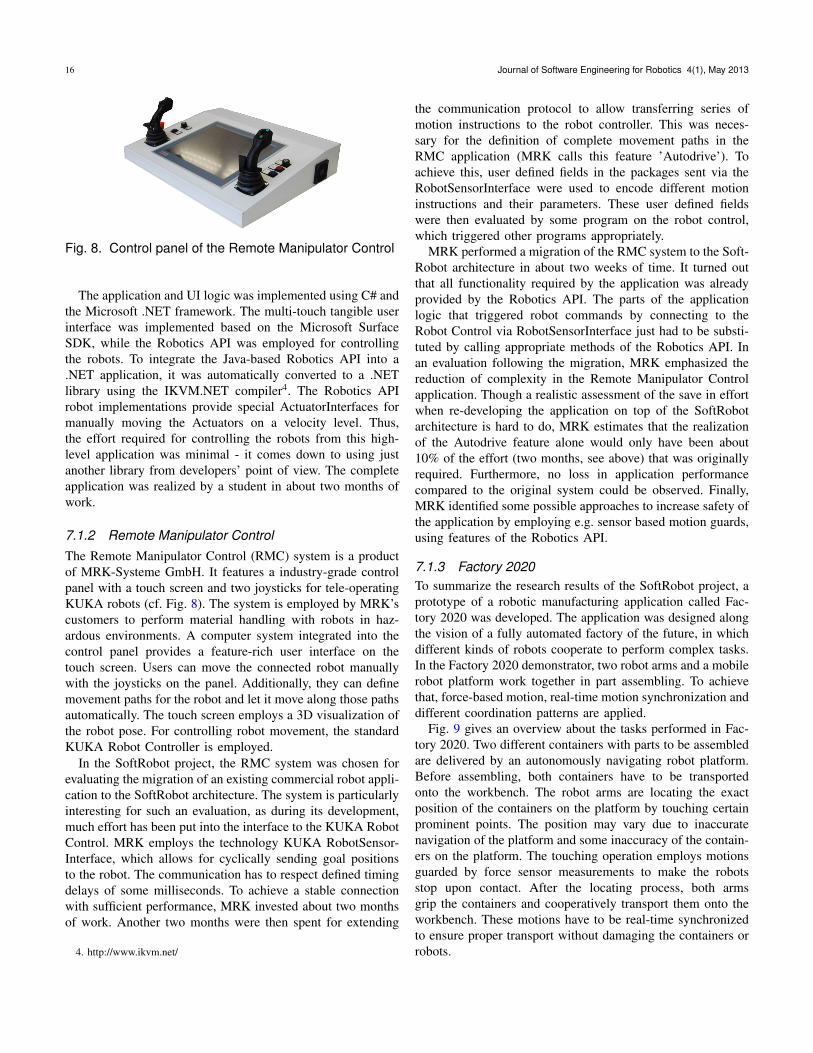
16 Journal of Software Engineering for Robotics 4(1), May 2013
Fig. 8. Control panel of the Remote Manipulator Control
The application and UI logic was implemented using C# andthe Microsoft .NET framework. The multi-touch tangible userinterface was implemented based on the Microsoft SurfaceSDK, while the Robotics API was employed for controllingthe robots. To integrate the Java-based Robotics API into a.NET application, it was automatically converted to a .NETlibrary using the IKVM.NET compiler4. The Robotics APIrobot implementations provide special ActuatorInterfaces formanually moving the Actuators on a velocity level. Thus,the effort required for controlling the robots from this high-level application was minimal - it comes down to using justanother library from developers’ point of view. The completeapplication was realized by a student in about two months ofwork.
7.1.2 Remote Manipulator ControlThe Remote Manipulator Control (RMC) system is a productof MRK-Systeme GmbH. It features a industry-grade controlpanel with a touch screen and two joysticks for tele-operatingKUKA robots (cf. Fig. 8). The system is employed by MRK’scustomers to perform material handling with robots in haz-ardous environments. A computer system integrated into thecontrol panel provides a feature-rich user interface on thetouch screen. Users can move the connected robot manuallywith the joysticks on the panel. Additionally, they can definemovement paths for the robot and let it move along those pathsautomatically. The touch screen employs a 3D visualization ofthe robot pose. For controlling robot movement, the standardKUKA Robot Controller is employed.
In the SoftRobot project, the RMC system was chosen forevaluating the migration of an existing commercial robot appli-cation to the SoftRobot architecture. The system is particularlyinteresting for such an evaluation, as during its development,much effort has been put into the interface to the KUKA RobotControl. MRK employs the technology KUKA RobotSensor-Interface, which allows for cyclically sending goal positionsto the robot. The communication has to respect defined timingdelays of some milliseconds. To achieve a stable connectionwith sufficient performance, MRK invested about two monthsof work. Another two months were then spent for extending
4. http://www.ikvm.net/
the communication protocol to allow transferring series ofmotion instructions to the robot controller. This was neces-sary for the definition of complete movement paths in theRMC application (MRK calls this feature ’Autodrive’). Toachieve this, user defined fields in the packages sent via theRobotSensorInterface were used to encode different motioninstructions and their parameters. These user defined fieldswere then evaluated by some program on the robot control,which triggered other programs appropriately.
MRK performed a migration of the RMC system to the Soft-Robot architecture in about two weeks of time. It turned outthat all functionality required by the application was alreadyprovided by the Robotics API. The parts of the applicationlogic that triggered robot commands by connecting to theRobot Control via RobotSensorInterface just had to be substi-tuted by calling appropriate methods of the Robotics API. Inan evaluation following the migration, MRK emphasized thereduction of complexity in the Remote Manipulator Controlapplication. Though a realistic assessment of the save in effortwhen re-developing the application on top of the SoftRobotarchitecture is hard to do, MRK estimates that the realizationof the Autodrive feature alone would only have been about10% of the effort (two months, see above) that was originallyrequired. Furthermore, no loss in application performancecompared to the original system could be observed. Finally,MRK identified some possible approaches to increase safety ofthe application by employing e.g. sensor based motion guards,using features of the Robotics API.
7.1.3 Factory 2020To summarize the research results of the SoftRobot project, aprototype of a robotic manufacturing application called Fac-tory 2020 was developed. The application was designed alongthe vision of a fully automated factory of the future, in whichdifferent kinds of robots cooperate to perform complex tasks.In the Factory 2020 demonstrator, two robot arms and a mobilerobot platform work together in part assembling. To achievethat, force-based motion, real-time motion synchronization anddifferent coordination patterns are applied.
Fig. 9 gives an overview about the tasks performed in Fac-tory 2020. Two different containers with parts to be assembledare delivered by an autonomously navigating robot platform.Before assembling, both containers have to be transportedonto the workbench. The robot arms are locating the exactposition of the containers on the platform by touching certainprominent points. The position may vary due to inaccuratenavigation of the platform and some inaccuracy of the contain-ers on the platform. The touching operation employs motionsguarded by force sensor measurements to make the robotsstop upon contact. After the locating process, both armsgrip the containers and cooperatively transport them onto theworkbench. These motions have to be real-time synchronizedto ensure proper transport without damaging the containers orrobots.
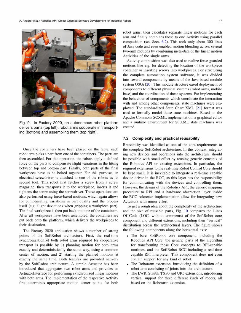
A. Angerer et al./ Robotics API: Object-Oriented Software Development for Industrial Robots 17
Fig. 9. In Factory 2020, an autonomous robot platformdelivers parts (top left), robot arms cooperate in transport-ing (bottom) and assembling them (top right).
Once the containers have been placed on the table, eachrobot arm picks a part from one of the containers. The parts arethen assembled. For this operation, the robots apply a definedforce on the parts to compensate slight variations in the fittingbetween top and bottom part. Finally, both parts of the finalworkpiece have to be bolted together. For this purpose, anelectrical screwdriver is attached to one of the robots as itssecond tool. This robot first fetches a screw from a screwmagazine, then transports it to the workpiece, inserts it andtightens the screw using the screwdriver. These operations arealso performed using force-based motions, which again allowsfor compensating variations in part quality and the processitself (e.g. slight deviations when gripping a workpiece part).The final workpiece is then put back into one of the containers.After all workpieces have been assembled, the containers areput back onto the platform, which delivers the workpieces totheir destination.
The Factory 2020 application shows a number of strongpoints of the SoftRobot architecture. First, the real-timesynchronization of both robot arms required for cooperativetransport is possible by 1) planning motion for both armsexactly and deterministically the same way, using a commoncenter of motion, and 2) starting the planned motions atexactly the same time. Both features are provided nativelyby the SoftRobot architecture. A simple Actuator has beenintroduced that aggregates two robot arms and provides anActuatorInterface for performing synchronized linear motionswith both arms. The implementation of the respective Activityfirst determines appropriate motion center points for both
robot arms, then calculates separate linear motions for eacharm and finally combines those to one Activity using parallelcomposition (see Sect. 6.2). This took only about 300 linesof Java code and even enabled motion blending across severaltwo-arm motions by combining meta-data of the linear motionActivities of the single arms.
Activity composition was also used to realize force-guardedmotions like e.g. for detecting the location of the workpiececontainer or inserting screws into workpieces. For structuringthe complete automation system software, it was dividedinto several components by means of the Java-based modulesystem OSGi [20]. This module structure eased deployment ofcomponents to different physical systems (robot arms, mobilebase) and the coordination of those systems. For implementingthe behaviour of components which coordinate the interactionwith and among other components, state machines were em-ployed. The standardized State Chart XML [21] format wasused to formally model those state machines. Based on theApache Commons SCXML implementation, a graphical editorand a runtime environment for SCXML state machines wascreated.
7.2 Complexity and practical reusability
Reusability was identified as one of the core requirements tothe complete SoftRobot architecture. In this context, integrat-ing new devices and operations into the architecture shouldbe possible with small effort by reusing generic concepts ofthe Robotics API or existing extensions. In particular, therequired extensions to the real-time Robot Control Core shouldbe kept small. It is inevitable to integrate a real-time capabledevice driver in the RCC, as this layer has the responsibilityfor communicating with the devices and controlling them.However, the design of the Robotics API, the generic mappingprocedure to RPI and a hardware abstraction layer insidethe RCC reference implementation allow for integrating newActuators with minor effort.
To get a rough idea about the complexity of the architectureand the size of reusable parts, Fig. 10 compares the LinesOf Code (LOC, without comments) of the SoftRobot corecomponent and different extensions, including their “vertical”distribution across the architectural layers. The figure showsthe following components along the horizontal axis:
• The bare SoftRobot core component, including theRobotics API Core, the generic parts of the algorithmfor transforming those Core concepts to RPI-capableruntimes, and the SoftRobot RCC including a real-timecapable RPI interpreter. This component does not evencontain support for any kind of robot.
• The Robotarm extension, introducing the definition of arobot arm consisting of joints into the architecture.
• The LWR, Staubli TX90 and UR5 extensions, introducingvertical support for three different kinds of robots, allbased on the Robotarm extension.
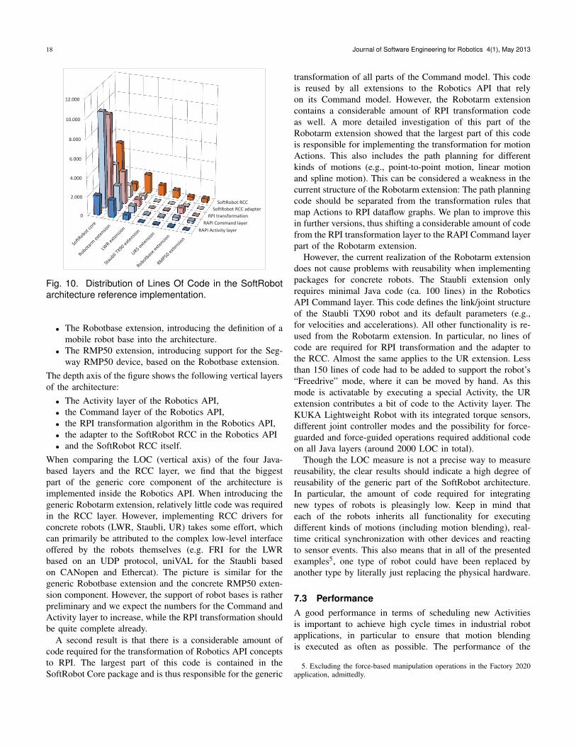
18 Journal of Software Engineering for Robotics 4(1), May 2013
RAPI Activity layer
RAPI Command layer
RPI transformation
SoftRobot RCC adapter
SoftRobot RCC
0
2.000
4.000
6.000
8.000
10.000
12.000
Fig. 10. Distribution of Lines Of Code in the SoftRobotarchitecture reference implementation.
• The Robotbase extension, introducing the definition of amobile robot base into the architecture.
• The RMP50 extension, introducing support for the Seg-way RMP50 device, based on the Robotbase extension.
The depth axis of the figure shows the following vertical layersof the architecture:
• The Activity layer of the Robotics API,• the Command layer of the Robotics API,• the RPI transformation algorithm in the Robotics API,• the adapter to the SoftRobot RCC in the Robotics API• and the SoftRobot RCC itself.
When comparing the LOC (vertical axis) of the four Java-based layers and the RCC layer, we find that the biggestpart of the generic core component of the architecture isimplemented inside the Robotics API. When introducing thegeneric Robotarm extension, relatively little code was requiredin the RCC layer. However, implementing RCC drivers forconcrete robots (LWR, Staubli, UR) takes some effort, whichcan primarily be attributed to the complex low-level interfaceoffered by the robots themselves (e.g. FRI for the LWRbased on an UDP protocol, uniVAL for the Staubli basedon CANopen and Ethercat). The picture is similar for thegeneric Robotbase extension and the concrete RMP50 exten-sion component. However, the support of robot bases is ratherpreliminary and we expect the numbers for the Command andActivity layer to increase, while the RPI transformation shouldbe quite complete already.
A second result is that there is a considerable amount ofcode required for the transformation of Robotics API conceptsto RPI. The largest part of this code is contained in theSoftRobot Core package and is thus responsible for the generic
transformation of all parts of the Command model. This codeis reused by all extensions to the Robotics API that relyon its Command model. However, the Robotarm extensioncontains a considerable amount of RPI transformation codeas well. A more detailed investigation of this part of theRobotarm extension showed that the largest part of this codeis responsible for implementing the transformation for motionActions. This also includes the path planning for differentkinds of motions (e.g., point-to-point motion, linear motionand spline motion). This can be considered a weakness in thecurrent structure of the Robotarm extension: The path planningcode should be separated from the transformation rules thatmap Actions to RPI dataflow graphs. We plan to improve thisin further versions, thus shifting a considerable amount of codefrom the RPI transformation layer to the RAPI Command layerpart of the Robotarm extension.
However, the current realization of the Robotarm extensiondoes not cause problems with reusability when implementingpackages for concrete robots. The Staubli extension onlyrequires minimal Java code (ca. 100 lines) in the RoboticsAPI Command layer. This code defines the link/joint structureof the Staubli TX90 robot and its default parameters (e.g.,for velocities and accelerations). All other functionality is re-used from the Robotarm extension. In particular, no lines ofcode are required for RPI transformation and the adapter tothe RCC. Almost the same applies to the UR extension. Lessthan 150 lines of code had to be added to support the robot’s“Freedrive” mode, where it can be moved by hand. As thismode is activatable by executing a special Activity, the URextension contributes a bit of code to the Activity layer. TheKUKA Lightweight Robot with its integrated torque sensors,different joint controller modes and the possibility for force-guarded and force-guided operations required additional codeon all Java layers (around 2000 LOC in total).
Though the LOC measure is not a precise way to measurereusability, the clear results should indicate a high degree ofreusability of the generic part of the SoftRobot architecture.In particular, the amount of code required for integratingnew types of robots is pleasingly low. Keep in mind thateach of the robots inherits all functionality for executingdifferent kinds of motions (including motion blending), real-time critical synchronization with other devices and reactingto sensor events. This also means that in all of the presentedexamples5, one type of robot could have been replaced byanother type by literally just replacing the physical hardware.
7.3 PerformanceA good performance in terms of scheduling new Activitiesis important to achieve high cycle times in industrial robotapplications, in particular to ensure that motion blendingis executed as often as possible. The performance of the
5. Excluding the force-based manipulation operations in the Factory 2020application, admittedly.
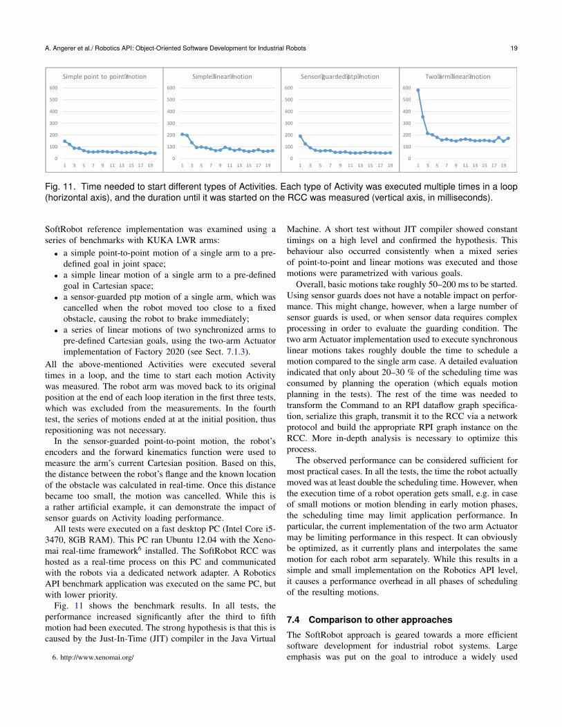
A. Angerer et al./ Robotics API: Object-Oriented Software Development for Industrial Robots 19
0
100
200
300
400
500
600
1 3 5 7 9 11 13 15 17 19
Simple point to point motion
0
100
200
300
400
500
600
1 3 5 7 9 11 13 15 17 19
Simple linear motion
0
100
200
300
400
500
600
1 3 5 7 9 11 13 15 17 19
Two arm linear motion
0
100
200
300
400
500
600
1 3 5 7 9 11 13 15 17 19
Sensor guarded ptp motion
Fig. 11. Time needed to start different types of Activities. Each type of Activity was executed multiple times in a loop(horizontal axis), and the duration until it was started on the RCC was measured (vertical axis, in milliseconds).
SoftRobot reference implementation was examined using aseries of benchmarks with KUKA LWR arms:
• a simple point-to-point motion of a single arm to a pre-defined goal in joint space;
• a simple linear motion of a single arm to a pre-definedgoal in Cartesian space;
• a sensor-guarded ptp motion of a single arm, which wascancelled when the robot moved too close to a fixedobstacle, causing the robot to brake immediately;
• a series of linear motions of two synchronized arms topre-defined Cartesian goals, using the two-arm Actuatorimplementation of Factory 2020 (see Sect. 7.1.3).
All the above-mentioned Activities were executed severaltimes in a loop, and the time to start each motion Activitywas measured. The robot arm was moved back to its originalposition at the end of each loop iteration in the first three tests,which was excluded from the measurements. In the fourthtest, the series of motions ended at at the initial position, thusrepositioning was not necessary.
In the sensor-guarded point-to-point motion, the robot’sencoders and the forward kinematics function were used tomeasure the arm’s current Cartesian position. Based on this,the distance between the robot’s flange and the known locationof the obstacle was calculated in real-time. Once this distancebecame too small, the motion was cancelled. While this isa rather artificial example, it can demonstrate the impact ofsensor guards on Activity loading performance.
All tests were executed on a fast desktop PC (Intel Core i5-3470, 8GB RAM). This PC ran Ubuntu 12.04 with the Xeno-mai real-time framework6 installed. The SoftRobot RCC washosted as a real-time process on this PC and communicatedwith the robots via a dedicated network adapter. A RoboticsAPI benchmark application was executed on the same PC, butwith lower priority.
Fig. 11 shows the benchmark results. In all tests, theperformance increased significantly after the third to fifthmotion had been executed. The strong hypothesis is that this iscaused by the Just-In-Time (JIT) compiler in the Java Virtual
6. http://www.xenomai.org/
Machine. A short test without JIT compiler showed constanttimings on a high level and confirmed the hypothesis. Thisbehaviour also occurred consistently when a mixed seriesof point-to-point and linear motions was executed and thosemotions were parametrized with various goals.
Overall, basic motions take roughly 50–200 ms to be started.Using sensor guards does not have a notable impact on perfor-mance. This might change, however, when a large number ofsensor guards is used, or when sensor data requires complexprocessing in order to evaluate the guarding condition. Thetwo arm Actuator implementation used to execute synchronouslinear motions takes roughly double the time to schedule amotion compared to the single arm case. A detailed evaluationindicated that only about 20–30 % of the scheduling time wasconsumed by planning the operation (which equals motionplanning in the tests). The rest of the time was needed totransform the Command to an RPI dataflow graph specifica-tion, serialize this graph, transmit it to the RCC via a networkprotocol and build the appropriate RPI graph instance on theRCC. More in-depth analysis is necessary to optimize thisprocess.
The observed performance can be considered sufficient formost practical cases. In all the tests, the time the robot actuallymoved was at least double the scheduling time. However, whenthe execution time of a robot operation gets small, e.g. in caseof small motions or motion blending in early motion phases,the scheduling time may limit application performance. Inparticular, the current implementation of the two arm Actuatormay be limiting performance in this respect. It can obviouslybe optimized, as it currently plans and interpolates the samemotion for each robot arm separately. While this results in asimple and small implementation on the Robotics API level,it causes a performance overhead in all phases of schedulingof the resulting motions.
7.4 Comparison to other approaches
The SoftRobot approach is geared towards a more efficientsoftware development for industrial robot systems. Largeemphasis was put on the goal to introduce a widely used
20 Journal of Software Engineering for Robotics 4(1), May 2013
standard programming language to industrial robot systems,replacing proprietary, vendor-specific robot languages. Thiswas driven by the strong belief of all project partners thatprogramming robot applications is not fundamentally differentfrom programming other types of applications. This sectionwill evaluate our approach in comparison to existing robotprogramming approaches from academia and industry.
7.4.1 Proprietary robot programming languagesFor comparing the SoftRobot architecture and its program-ming interface to proprietary robot languages, we take theKUKA Robot Language (KRL) as an example7. When justcomparing the interface towards robot programmers, KRL hasthe advantage of a more minimalistic, imperative programmingmodel. The Robotics API introduces a much more flexible, butalso more complicated object-oriented programming model.However, when applications get more complex, developersprofit from a full-fledged modern programming language sup-porting a large number of design patterns for structuring code.There exist powerful IDEs as well as a large number of othertools and libraries. In particular, tools for creating DSLs allowfor introducing new domain-specific programming interfacesrapidly. As a proof of concept, and to evaluate backwardcompatibility to existing robot programs, one of our studentscreated a KRL interpreter on top of the Robotics API in hismaster thesis [22].
Considering functionality, the SoftRobot architecture pro-vides native support for tight integration of sensor feedbackinto robot operations. Furthermore, forming robots to teamsthat collaborate in real-time is easily possible. KRL providessupport for connecting multiple robot controllers to achievereal-time robot cooperation as well. This implies writingone program for each robot and synchronizing with specialstatements. We compared the effort required for realizing ascenario similar to the cooperative container transport in theFactory 2020 application (see Sect. 7.1.3). An experiencedKRL programmer invested more than 3 times the effort to lettwo robots perform cooperative transport of a single workpiececompared to an experienced Robotics API developer.
7.4.2 Existing object-oriented approachedThere are several academic approaches providing robot-specific libraries for general-purpose languages. Early exam-ples are RCCL [23] in C and PasRo [24] in Pascal. Withthe emergence of object-oriented languages, robot-specificlibraries for these languages have been implemented, too.Examples are ZERO++ [25], MRROC++ [26]. RIPE [27], theRobotic Platform [28] and SIMOO-RT [29]. These frame-works employ object orientation for introducing hardwareabstraction. However, in general a low level of abstraction isused so that developers need profound knowledge in robotics
7. Other vendor-specific languages may slightly differ, but the main evalu-ation points should yield the same results.
and often in real-time programming. Using C or C++ mayresult in a better runtime performance compared to Java,which is executed on a virtual machine rather than directlyon the physical hardware. However, we are confident that theworkflow-related parts of robot applications are executed fastenough also in Java, and our practical experiences confirm this.(Real-)Time critical operations are delegated to the RCC, asexplained. This abstraction for real-time tasks is one importantparadigm of the SoftRobot architecture that cannot be foundin most other object-oriented robot programming frameworks.One exception is the ORCCAD architecture introduced byBorrelly et al. [30]. In fact, this project takes a similar approachin that a real-time abstraction is provided for complex robottasks. However, the workflow parts of robotic applicationsthat are not real-time critical have to be implemented in aproprietary language (MAESTRO) designed by the authors.Using a standard language like in the SoftRobot approach hasmany advantages for application development (see above) and,in the case of a language with automatic memory management,relieves developers from memory management issues theyhave to care about in C/++.
7.4.3 Component-based approaches in roboticsFor managing the complexity of modern autonomous robotsand large-scale distributed application scenarios, decomposi-tion of systems into components, composability of subsystemsand distribution of components have been identified as corerequirements (stated e.g. by Hagele et al. [5] and addressede.g. by Nesnas et al. [31], Finkemeyer et al. [32] and inparticular most component-based systems like Player [33],ROS [34] or ORCA [35]). This led to a trend for Component-Based Software Engineering in the past years (cf. Brugali etal.’s work [36], [37]). Many of the aforementioned compo-nent frameworks do not particularly support hard real-timeexecution of robot tasks, which makes it harder to achievethe precision required in industrial applications. Implementingthe workflow of an application in a component-based systemusually requires multiple configuration and coordination com-ponents (c.f. Prassler et al. [38]). Coordination componentsare commonly implemented using state machine mechanisms(e.g. rFSM [39] or ROS smach [40]). While this is certainlywell suited for a certain class of systems, we believe thatfor implementing complex, partly real-time critical workflowsin industrial application scenarios, an object-oriented APIlike provided in the SoftRobot approach is better suited. Forcomposing larger automation systems, we are however fol-lowing the component-based approach as well. As previouslymentioned (Sect. 7.1.3), the Factory 2020 application is built ofOSGi components. In this case, using components to structurethe systems and realizing the workflow of complex processsteps (e.g. cooperative transport, workpiece assembling) basedon the Robotics API proved to be a good combination. Weare continuing research about the distribution of automationprocesses to component architectures.
A. Angerer et al./ Robotics API: Object-Oriented Software Development for Industrial Robots 21
8 CONCLUSION
This article presented the SoftRobot architecture, a lay-ered, vendor-independent software architecture for industrialrobotics application development. A special focus was puton presenting the design of the object-oriented Robotics API,which provides a powerful and flexible programming interface.It is designed to realize complex robotic applications includingmulti-robot cooperation and integration of sensors in guidingand guarding robot operations. The particular contributions ofthe SoftRobot approach are:
1) An abstraction for real-time critical robot operations,which can be specified using dataflow graphs definedin the RPI language.
2) An object-oriented framework, designed according tothe requirements of the industrial robotics domain, andintegrating a model for robot operations which employsthe aforementioned real-time abstraction.
We have evaluated the practical usefulness of the SoftRobotapproach by creating a reference implementation of a RobotControl Core and the Robotics API, and using this implemen-tation to realize complex applications. Some examples havebeen presented in this work, including real-time synchronized,blended motion of two robot arms. The overall performanceof the reference architecture can be considered adequate, butleaves room for improvements.
An increasing number of undergraduate students are work-ing with the reference implementation. We also started toarrange hackathons, e.g. with the KUKA youBot. For thispurpose, we provide a youBot extension for the SoftRobotarchitecture. The results of these hackathons as well as thefeedback from the students that attended them are very promis-ing: The majority of participants were computer science stu-dents that have little or no experience with any kind of robots.Though, they managed to create complex tech-demos withthe youBots, e.g. writing user-defined words on a whiteboardusing a combination of robot arm and base movement.
An evaluation of the distribution of code throughout theframework structure showed clear indication that the designof the architecture supports extensibility and reusability. Theintegration of new robotics devices as well as new functionalityfor those devices (or already existing devices) requires minoreffort and can re-use many concepts that are already imple-mented. We are working towards integrating a broader varietyof devices. Robot arms by different manufacturers (KUKA,Staubli, Universal Robots) are supported already, which il-lustrates the vendor-independent approach. Currently, mainlyserial robot structures have been considered. Integration ofparallel or hybrid structures (like in many humanoid robots)will be considered in the future, which might raise the need forother kinds of synchronization paradigms for Actuators in thearchitecture. Furthermore, we will continue to investigate theintegration of this architecture with component-based systemslike OSGi to find the right level of use for each paradigm.
Finally, we are developing an ecosystem of tools around theSoftRobot architecture to better support users, for instance toallow teaching robot motions with the help of tablet devices.
ACKNOWLEDGMENTS
The authors would like to thank the project partners fromKUKA Laboratories GmbH and MRK-Systeme GmbH, Jun.-Prof. Frank Ortmeier from Magdeburg University as well asVDI/VDE-IT for their support and cooperation in setting upand successfully conducting the SoftRobot project.
REFERENCES
[1] Willow Garage, Inc. PR2 - Overview. [Online]. Available: http://www.willowgarage.com/pages/pr2/overview 1
[2] Cotesys Central Robotics Laboratory II. TUM-Rosie. TU Munich.[Online]. Available: http://ias.cs.tum.edu/robots/tum-rosie 1
[3] J. N. Pires, “Robotics for small and medium enterprises: Control andprogramming challenges,” Industrial Robot, vol. 33, no. 6, 2006. 1
[4] M. Hagele, T. Skordas, S. Sagert, R. Bischoff, T. Brogardh, and M. Dres-selhaus, “Industrial robot automation,” European Robotics Network,White Paper, Jul. 2005. 1, 2, 2
[5] M. Hagele, K. Nilsson, and J. N. Pires, “Industrial robotics,” in SpringerHandbook of Robotics, B. Siciliano and O. Khatib, Eds. Berlin,Heidelberg: Springer, 2008, ch. 42, pp. 963–986. 2, 1, 7.4.3
[6] J. N. Pires, G. Veiga, and R. Araujo, “Programming by demonstrationin the coworker scenario for SMEs,” Industrial Robot, vol. 36, no. 1,pp. 73–83, 2009. 2
[7] J. G. Ge and X. G. Yin, “An object oriented robot programmingapproach in robot served plastic injection molding application,” inRobotic Welding, Intelligence & Automation, ser. Lect. Notes in Control& Information Sciences, vol. 362. Springer, 2007, pp. 91–97. 2
[8] Blackbird Robotersysteme GmbH. Blackbird Robotersysteme GmbH.[Online]. Available: http://www.blackbird-robotics.de 2
[9] Hub Technologies. KUKA Robotics. [Online]. Available: http://www.kuka-robotics.com/germany/en/products/software/hub technologies 2
[10] C. Bredin, “ABB MultiMove functionality heralds a new era in robotapplications,” ABB Review, vol. 1, pp. 26–29, 2005. 2
[11] R. T. Vaughan and B. Gerkey, “Really reusable robot code andthe player/stage project,” in Software Engineering for ExperimentalRobotics, ser. Springer Tracts in Adv. Robotics, D. Brugali, Ed.Springer, April 2007, vol. 30. [Online]. Available: http://dx.doi.org/10.1007/978-3-540-68951-5 1610.1007/978-3-540-68951-5 16 3
[12] H. Bruyninckx, “Open robot control software: the OROCOS project,” inProc. 2001 IEEE Intl. Conf. on Robotics and Automation, Seoul, Korea,May 2001, pp. 2523–2528. 3, 3.1
[13] A. Hoffmann, A. Angerer, F. Ortmeier, M. Vistein, and W. Reif, “Hidingreal-time: A new approach for the software development of industrialrobots,” in Proc. 2009 IEEE/RSJ Intl. Conf. on Intelligent Robots andSystems, St. Louis, MO, USA, 2009. 3
[14] M. Vistein, A. Angerer, A. Hoffmann, A. Schierl, and W. Reif, “Interfac-ing industrial robots using realtime primitives,” in Proc. 2010 IEEE Intl.Conf. on Automation and Logistics (ICAL 2010), Hong Kong, China.IEEE, Aug. 2010, pp. 468–473. 3
[15] ——, “Instantaneous switching between real-time commands for con-tinuous execution of complex robotic tasks,” in Proc. 2012 Intl. Conf. onMechatronics and Automation, Chengdu, China, Aug. 2012, pp. 1329–1334. 3.1, 4.4, 6
[16] A. Schierl, A. Angerer, A. Hoffmann, M. Vistein, and W. Reif, “Fromrobot commands to real-time robot control - transforming high-levelrobot commands into real-time dataflow graphs,” in Proc. 2012 Intl.Conf. on Informatics in Control, Automation and Robotics, Rome, Italy,2012. 3.2, 4.4
[17] E. W. Dijkstra, “EWD 447: On the role of scientific thought,”Selected Writings on Computing: A Personal Perspective, pp. 60–66, 1982. [Online]. Available: http://www.cs.utexas.edu/users/EWD/ewd04xx/EWD447.PDF 5
22 Journal of Software Engineering for Robotics 4(1), May 2013
[18] R. J. Marks II, Introduction to Shannon Sampling and InterpolationTheory. Springer, 1991. 6.1
[19] A. Angerer, A. Bareth, A. Hoffmann, A. Schierl, M. Vistein, andW. Reif, “Two-arm robot teleoperation using a multi-touch tangibleuser interface,” in Proc. 2012 Intl. Conf. on Informatics in Control,Automation and Robotics, Rome, Italy, 2012. 7.1.1
[20] OSGi Core Release 5, OSGi Alliance Spec., Mar. 2012. [Online].Available: http://www.osgi.org/download/r5/osgi.core-5.0.0.pdf 7.1.3
[21] State Chart XML (SCXML): State Machine Notation for ControlAbstraction, W3C Working Draft 6, Dec. 2012. [Online]. Available:http://www.w3.org/TR/scxml/ 7.1.3
[22] H. Muhe, A. Angerer, A. Hoffmann, and W. Reif, “On reverse-engineering the KUKA Robot Language,” Workshop on Domain-SpecificLanguages and models for ROBotic systems, 2010 IEEE/RSJ Intl. Conf.on Intelligent Robots and Systems, Taipeh, Taiwan, 2010. 7.4.1
[23] V. Hayward and R. P. Paul, “Robot manipulator control under unixRCCL: A robot control C library,” International Journal of RoboticsResearch, vol. 5, no. 4, pp. 94–111, 1986. 7.4.2
[24] C. Blume and W. Jakob, Programming Languages for Industrial Robots.Springer-Verlag, 1986. 7.4.2
[25] C. Pelich and F. M. Wahl, “ZERO++: An OOP environment formultiprocessor robot control,” International Journal of Robotics andAutomation, vol. 12, no. 2, pp. 49–57, 1997. 7.4.2
[26] C. Zielinski, “Object-oriented robot programming,” Robotica, vol. 15,no. 1, pp. 41–48, 1997. 7.4.2
[27] D. J. Miller and R. C. Lennox, “An object-oriented environment forrobot system architectures,” in Proc. 1990 IEEE Intl. Conf. on Roboticsand Automation, Cincinnati, Ohio, USA, May 1990, pp. 352–361. 7.4.2
[28] M. S. Loffler, V. Chitrakaran, and D. M. Dawson, “Design and imple-mentation of the Robotic Platform,” Journal of Intelligent and RoboticSystem, vol. 39, pp. 105–129, 2004. 7.4.2
[29] L. B. Becker and C. E. Pereira, “SIMOO-RT – An object oriented frame-work for the development of real-time industrial automation systems,”IEEE Trans. Robot. Autom., vol. 18, no. 4, pp. 421–430, Aug. 2002.7.4.2
[30] J.-J. Borrelly, E. Coste-Maniere, B. Espiau, K. Kapellos, R. Pissard-Gibollet, D. Simon, and N. Turro, “The ORCCAD architecture,” Intl.Journal of Robotics Research, vol. 17, no. 4, pp. 338–359, Apr. 1998.7.4.2
[31] I. A. Nesnas, A. Wright, M. Bajracharya, R. Simmons, and T. Estlin,“CLARAty and challenges of developing interoperable robotic soft-ware,” in Proc. 2003 IEEE/RSJ Intl. Conf. on Intelligent Robots andSystems, Las Vegas, USA, Oct. 2003, pp. 2428–2435. 7.4.3
[32] B. Finkemeyer, T. Kroger, D. Kubus, M. Olschewski, and F. M. Wahl,“MiRPA: Middleware for robotic and process control applications,” inWorkshop on Measures and Procedures for the Evaluation of RobotArchitectures and Middleware. IEEE/RSJ Intl. Conf. on IntelligentRobots and Systems, San Diego, USA, Oct. 2007, pp. 76–90. 7.4.3
[33] T. Collett, B. MacDonald, and B. Gerkey, “Player 2.0: Toward a practicalrobot programming framework,” in Proc. 2005 Australasian Conf. onRobotics and Automation, Sydney, Australia, Dec. 2005. 7.4.3
[34] M. Quigley, K. Conley, B. P. Gerkey, J. Faust, T. Foote, J. Leibs,R. Wheeler, and A. Y. Ng, “ROS: an open-source Robot OperatingSystem,” in ICRA Workshop on Open Source Software, 2009. 7.4.3
[35] A. Makarenko, A. Brooks, and T. Kaupp, “Orca: Components forrobotics,” in Workshop on Robotic Standardization. IEEE/RSJ Intl. Conf.on Intelligent Robots and Systems, Beijing, China, Oct. 2006. 7.4.3
[36] D. Brugali and P. Scandurra, “Component-based robotic engineering(Part I),” IEEE Robotics & Automation Magazine, vol. 16, no. 4, pp.84–96, Dec. 2009. 7.4.3
[37] D. Brugali and A. Shakhimardanov, “Component-based robotic engi-neering (Part II),” IEEE Robotics & Automation Magazine, vol. 20, no. 1,Mar. 2010. 7.4.3
[38] E. Prassler, H. Bruyninckx, K. Nilsson, and A. Shakhimardanov,“The use of reuse for designing and manufacturing robots,” WhitePaper, June 2009. [Online]. Available: http://www.robot-standards.eu/Documents RoSta wiki/whitepaper reuse.pdf 7.4.3
[39] M. Klotzbucher and H. Bruyninckx, “Coordinating robotic tasks andsystems with rFSM statecharts,” J. Software Engineering for Robotics,vol. 3, no 1, pp. 28–56, 2012. 7.4.3
[40] ROS SMACH. [Online]. Available: http://ros.org/wiki/smach 7.4.3
Andreas Angerer received his B. Sc. degree incomputer science from the University of Augs-burg in 2007 and his M. Sc. degree in softwareengineering from the University of Augsburg,the TU Munchen and the Ludwig-Maximilians-Universitat Munchen in 2008. Currently, he isa member of the Institute for Software & Sys-tems Engineering (ISSE) at the University ofAugsburg. He was involved in several researchprojects in robotics and has published about15 refereed journal, conference and workshop
papers. His research interest covers software engineering for robotics, inparticular applying modern software engineering paradigms to robotics.
Alwin Hoffmann received his B. Sc. and M. Sc.degrees in information management from theTU Munchen and the University of Augsburg, in2005 and 2007, respectively, and his Diplomain Computer Science from the University ofAugsburg, in 2008. Currently, he is a memberof the ISSE and leads the robotics researchgroup there. He has published about 20 refer-eed scientific papers. His research interest cov-ers robotics, software engineering, and service-oriented architectures.
Andreas Schierl received his B. Sc. degree incomputer science from the University of Augs-burg in 2007, and the M. Sc. degree in softwareengineering from the University of Augsburg,the TU Munchen and the Ludwig-Maximilians-Universitat in 2009. Currently, he is a member ofthe ISSE and has published about 15 refereedjournal and conference papers. His researchinterest covers mobile robotics, software archi-tectures and software engineering in robotics.
Michael Vistein received his B. Sc. degree incomputer science from the University of Augs-burg in 2007 and his M. Sc. degree in softwareengineering from the University of Augsburg,the TU Munchen and the Ludwig-Maximilians-Universitat Munchen in 2008. Currently, he is amember of the ISEE and has published about 15refereed scientific papers. His research interestcovers software engineering for robotics, in par-ticular real-time task execution for robots.
Wolfgang Reif is full professor for software en-gineering at University of Augsburg where heis also vice-president and director of the Insti-tute for Software & Systems Engineering (ISSE).He received his doctoral degree in computerscience from the University of Karlsruhe wherehe worked mainly in safety, verification, and au-tomatic theorem proving. He held a professor-ship in software engineering at the University ofUlm from 1995 to 2000. His current researchinterests are software and systems engineering,
safety, reliability and security, organic computing, as well as software-driven mechatronics & robotics. In these areas, he is involved in nu-merous research projects both in fundamental as well as application-oriented research. Wolfgang Reif is author of a large number of scientificpublications, referee for numerous national funding agencies in Europeand the US, and is consultant to leading technology companies.