robust rate adaption in 802.11 networks · robust rate adaption in 802.11 ... why is it hard? 3...
TRANSCRIPT
Starsky H.Y. Wong, Hao Yang, Songwu Lu and Vaduvur Bharghavan
UCLA WiNG Research Group and
Meru Networks
Robust Rate Adaption in 802.11 networks
Presented by Diwaker GuptaCSE 291, 05/08/2007
Problem description
What is the problem? Why is it important? Why is it hard?
3
IEEE 802.11 Rate Adaptation
The 802.11 a/b/g/n standards allow the use of multiple transmission rates
802.11b, 4 rate options (1,2,5.5,11Mbps) 802.11a, 8 rate options (6,9,12,18,24,36,48,54 Mbps) 802.11g, 12 rate options (11a set + 11b set)
The method to select the transmission rate in real time is called “Rate Adaptation”
Rate adaptation is important yet unspecified by the 802.11 standards
4
Rate Adaptation Example
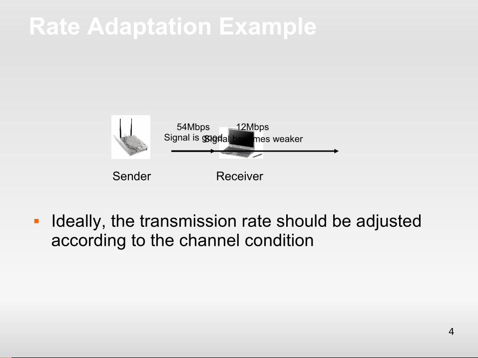
Ideally, the transmission rate should be adjusted according to the channel condition
Sender Receiver
54MbpsSignal is goodSignal becomes weaker
12Mbps
5
Importance of Rate Adaptation
Rate adaptation plays a critical role to the throughput performance
Rate too high → loss ratio increases → throughput decreases
Rate too low → under-utilize the capacity → throughput decreases
6
Design Challenge
Wireless channel exhibits rich channel dynamics in practical scenarios Random channel error Mobility-induced change Collisions induced by
Hidden-terminals Multiple contending clients
7
Related Work
Not compliant with the 802.11 standard RBAR, OAR, etc. Needs to change the standard specification
Standard compliant ARF, AARF, SampleRate, Onoe, AMRR,
CARA Cannot handle all channel dynamics Performance degradation in many cases
8
Goals and Contributions
Goals Improve throughput performance Robust against various dynamics 802.11 standard compliant, easy to implement
Contributions: Identify limitations of five design guidelines for existing
solutions Design, implement and evaluate the Robust Rate
Adaptation Algorithm (RRAA)
9
Outline
Experimental Methodology Critique on current design guidelines Design of RRAA Implementation and Evaluation Ongoing work
10
Experimental Methodology
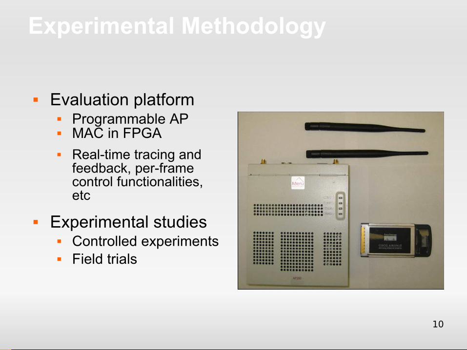
Evaluation platform Programmable AP MAC in FPGA Real-time tracing and
feedback, per-frame control functionalities, etc
Experimental studies Controlled experiments Field trials
11
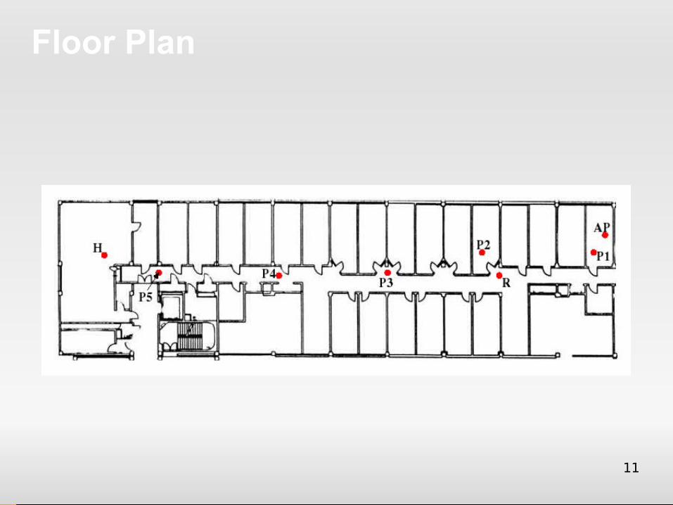
Floor Plan
12
Design guidelines in Existing Rate Adaptation
Most designs follow a few conceptually intuitive and seemingly effective guidelines Decrease rate upon severe loss Use deterministic success/loss patterns Use probe packets Use PHY-layer metrics Use long-term statistics
How well do they work in practice?
13
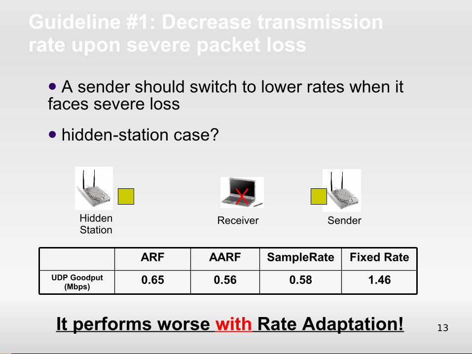
Guideline #1: Decrease transmission rate upon severe packet loss
1.460.580.560.65UDP Goodput (Mbps)
Fixed RateSampleRateAARFARF
SenderReceiverHiddenStation
A sender should switch to lower rates when it faces severe loss
hidden-station case?
It performs worse with Rate Adaptation!
14
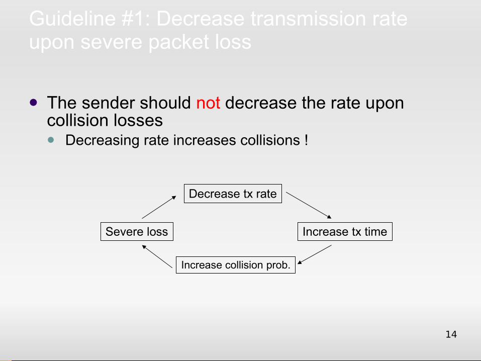
Guideline #1: Decrease transmission rate upon severe packet loss
The sender should not decrease the rate upon collision losses Decreasing rate increases collisions !
Increase collision prob.
Increase tx timeSevere loss
Decrease tx rate
15
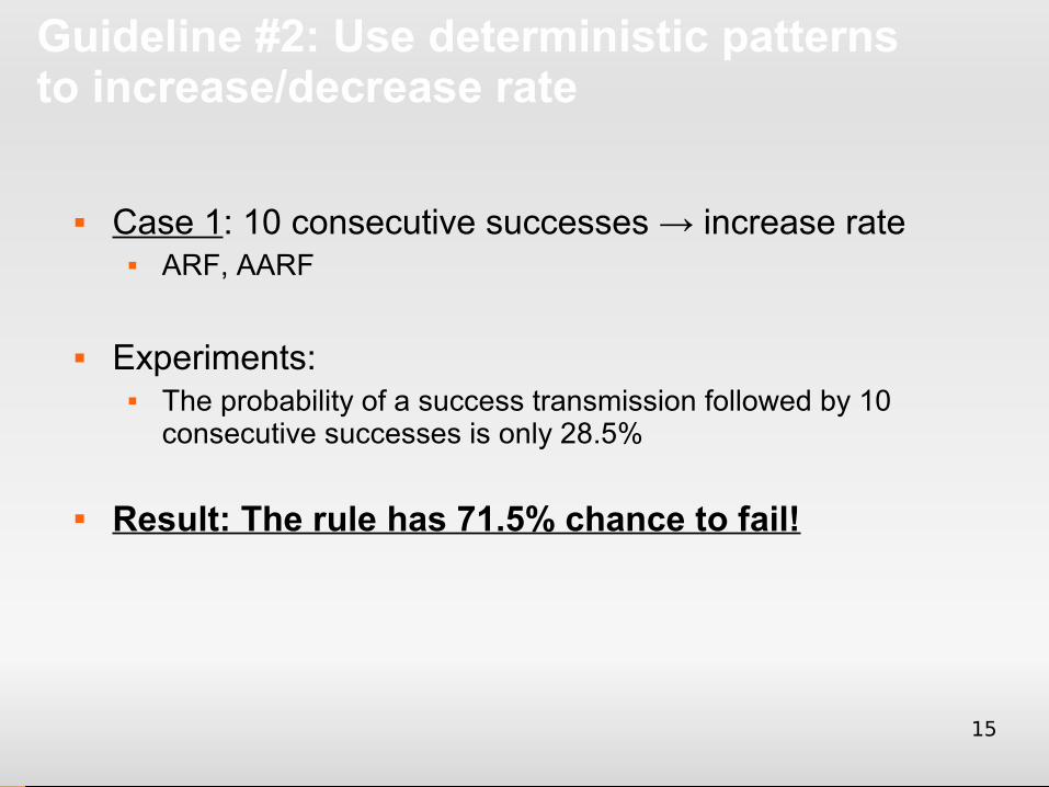
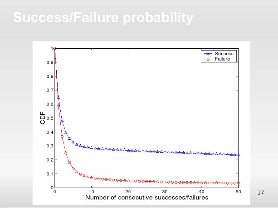
Guideline #2: Use deterministic patterns to increase/decrease rate
Case 1: 10 consecutive successes → increase rate ARF, AARF
Experiments: The probability of a success transmission followed by 10
consecutive successes is only 28.5%
Result: The rule has 71.5% chance to fail!
16
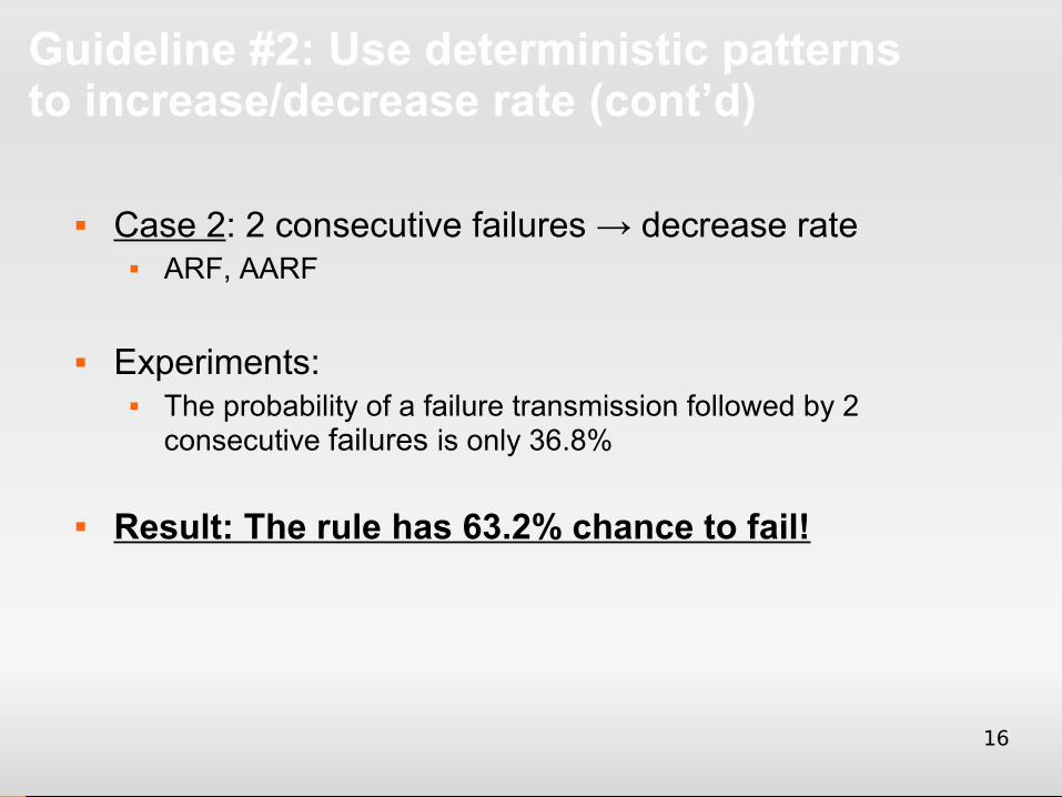
Guideline #2: Use deterministic patterns to increase/decrease rate (cont’d)
Case 2: 2 consecutive failures → decrease rate ARF, AARF
Experiments: The probability of a failure transmission followed by 2
consecutive failures is only 36.8%
Result: The rule has 63.2% chance to fail!
17
Success/Failure probability
18
Design guidelines (cont’d)
Other guidelines: #3: Use probe packets to assess possible
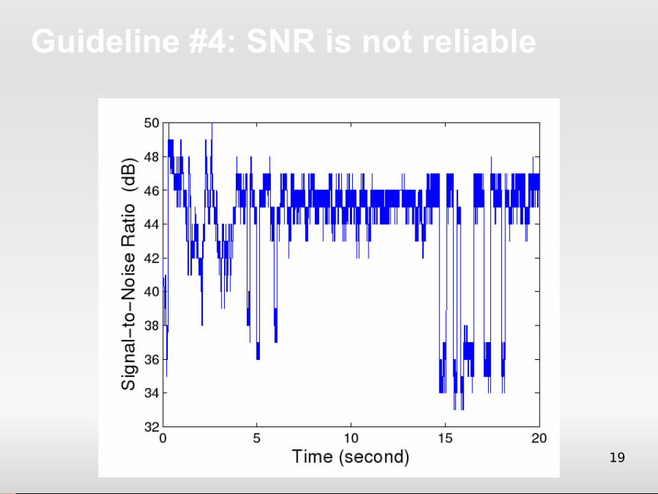
new rates #4: Use PHY metrics like SNR to infer new
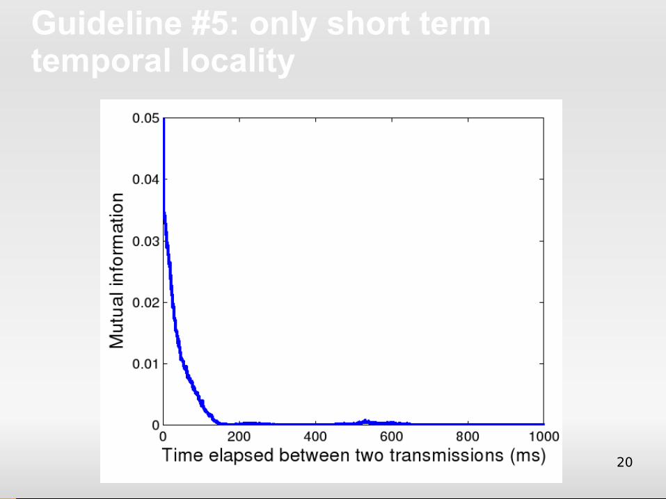
transmission rate #5: Long-term smoothened operation
produces the best average performance
All suffer from problems in practice!
19
Guideline #4: SNR is not reliable
20
Guideline #5: only short term temporal locality
21
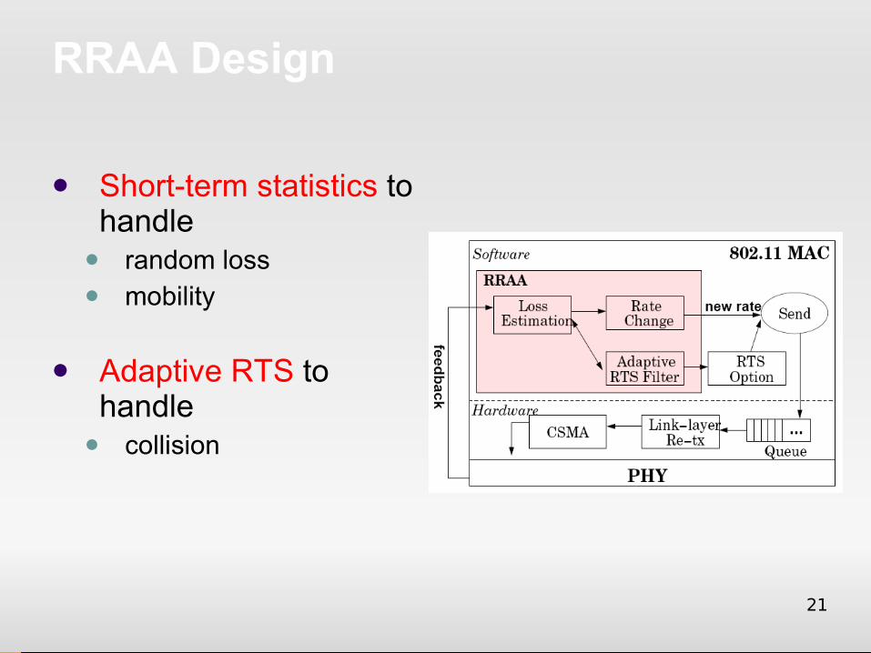
RRAA Design
Short-term statistics to handle
random loss mobility
Adaptive RTS to handle
collision
22
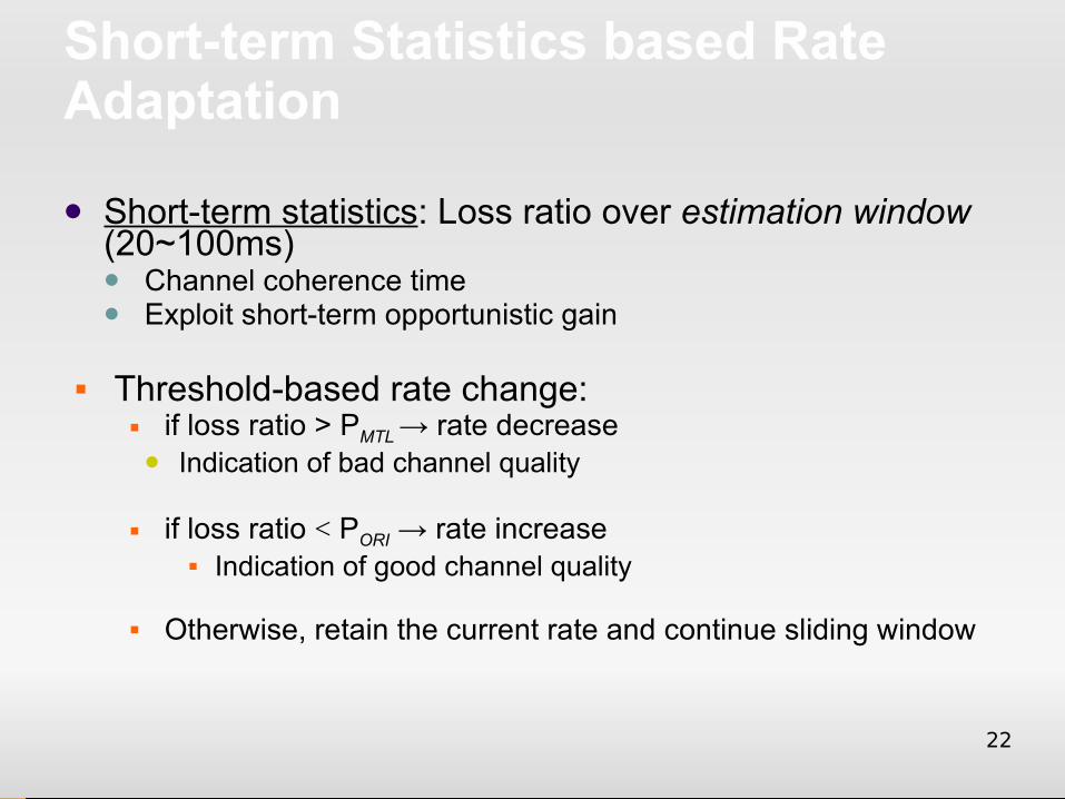
Short-term Statistics based Rate Adaptation
Short-term statistics: Loss ratio over estimation window (20~100ms) Channel coherence time Exploit short-term opportunistic gain
Threshold-based rate change: if loss ratio > PMTL → rate decrease Indication of bad channel quality
if loss ratio < PORI → rate increase Indication of good channel quality
Otherwise, retain the current rate and continue sliding window
23
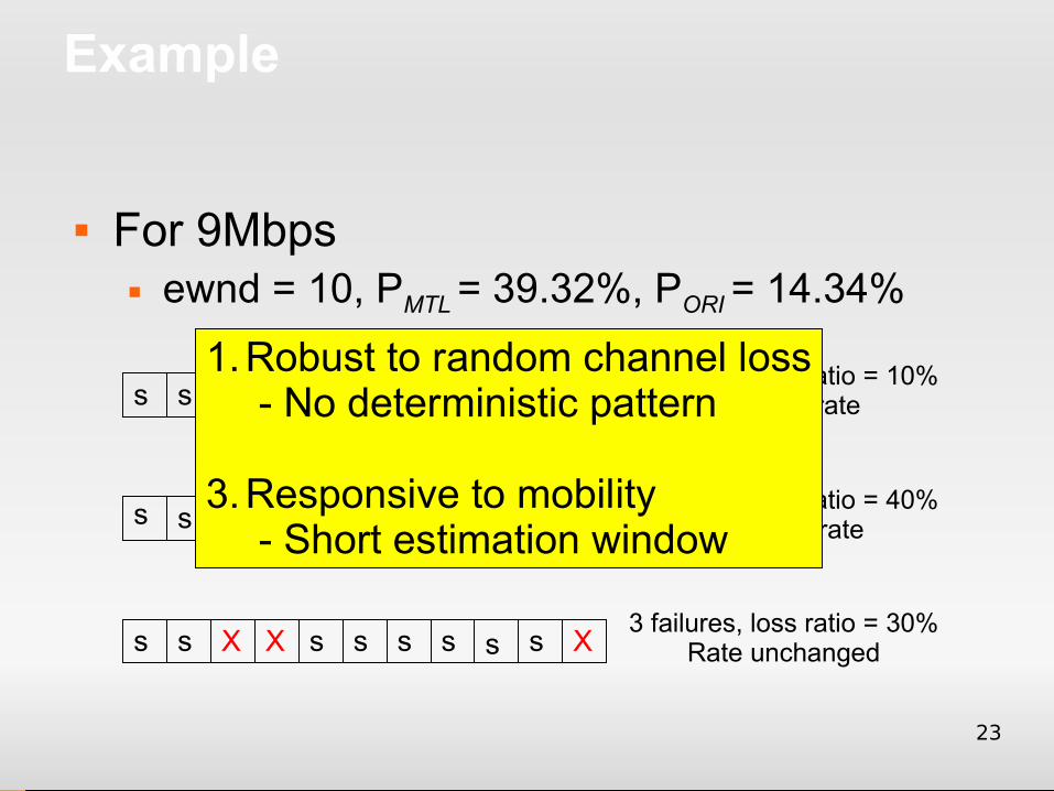
Example
For 9Mbps ewnd = 10, PMTL = 39.32%, PORI = 14.34%
s s s s s s s X s s
s X s X X s s Xs
s s X X s s s s s X
1 failures, loss ratio = 10%Increase rate
4 failures, loss ratio = 40%decrease rate
3 failures, loss ratio = 30%Rate unchanged
s
s
s
s
1.Robust to random channel loss- No deterministic pattern
3.Responsive to mobility- Short estimation window
24
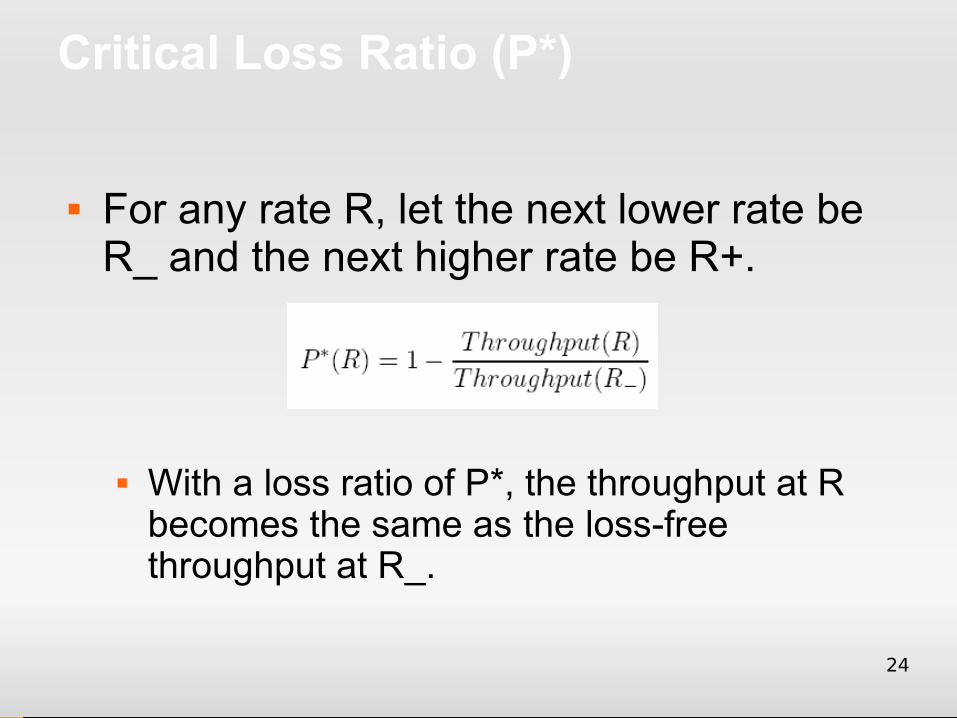
Critical Loss Ratio (P*)
For any rate R, let the next lower rate be R_ and the next higher rate be R+.
With a loss ratio of P*, the throughput at R becomes the same as the loss-free throughput at R_.
25
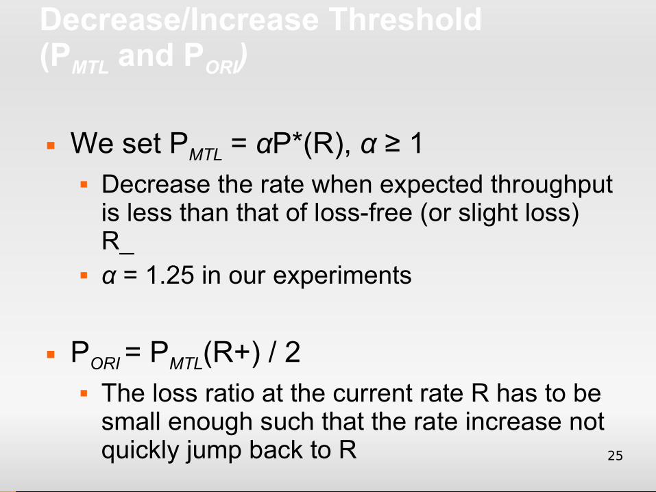
Decrease/Increase Threshold (PMTL and PORI)
We set PMTL = αP*(R), α ≥ 1 Decrease the rate when expected throughput
is less than that of loss-free (or slight loss) R_
α = 1.25 in our experiments
PORI = PMTL(R+) / 2 The loss ratio at the current rate R has to be
small enough such that the rate increase not quickly jump back to R
26
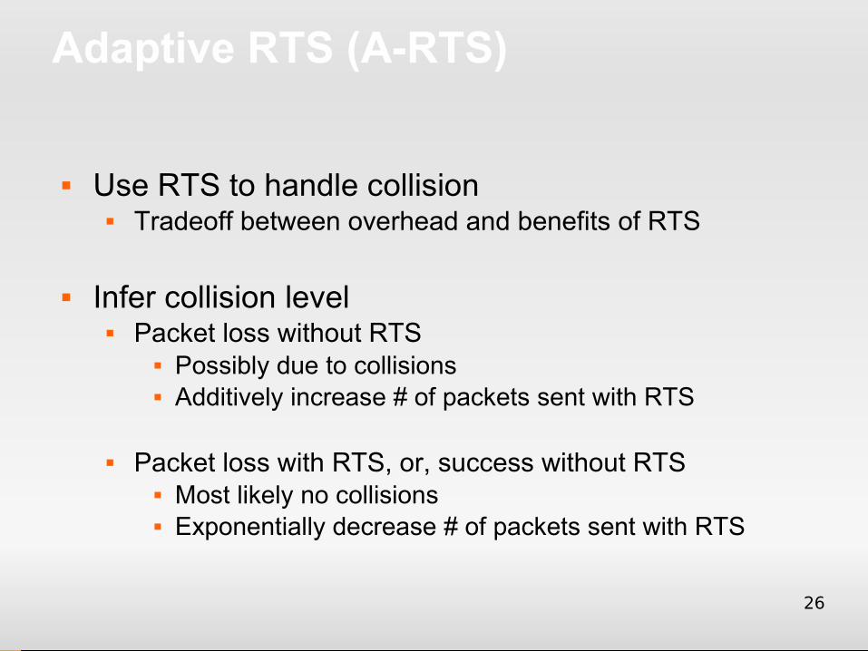
Adaptive RTS (A-RTS)
Use RTS to handle collision Tradeoff between overhead and benefits of RTS
Infer collision level Packet loss without RTS
Possibly due to collisions Additively increase # of packets sent with RTS
Packet loss with RTS, or, success without RTS Most likely no collisions Exponentially decrease # of packets sent with RTS
27
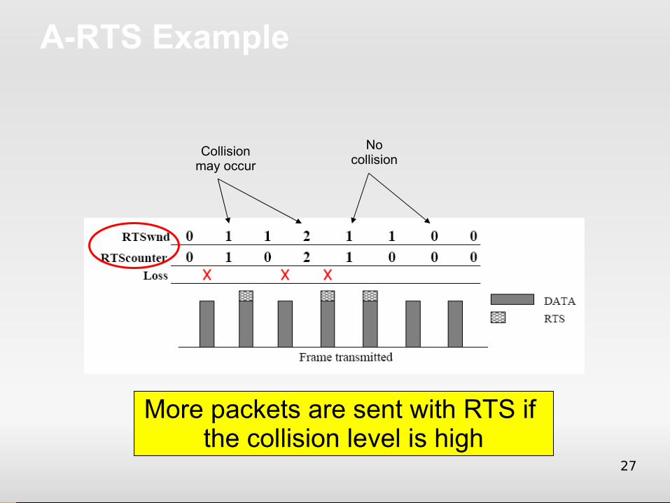
A-RTS Example
Collision may occur
Nocollision
More packets are sent with RTS if the collision level is high
28
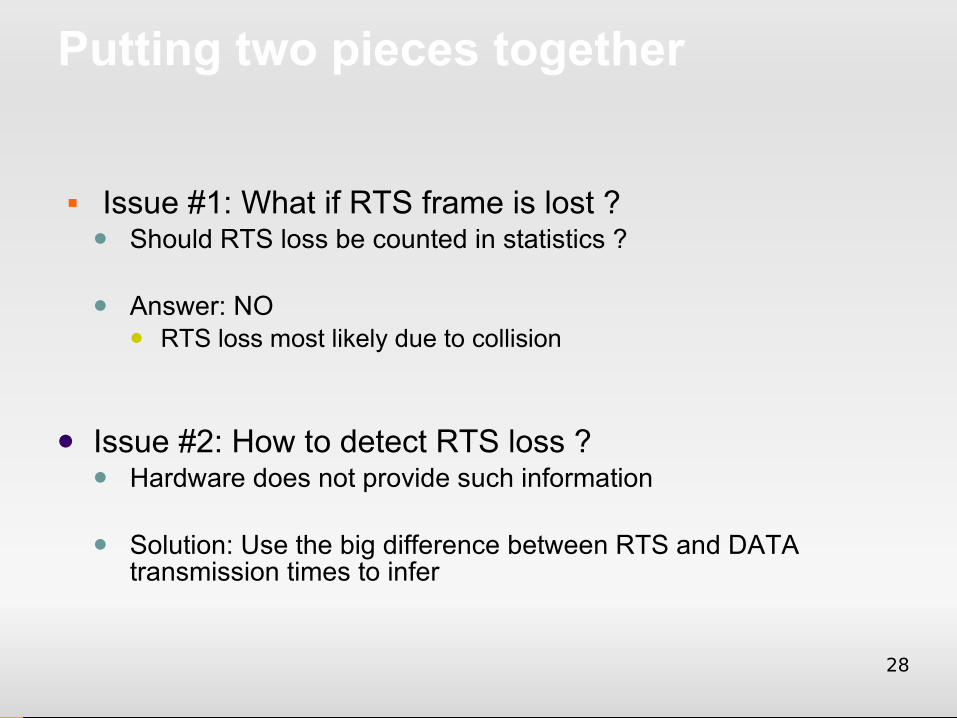
Putting two pieces together
Issue #1: What if RTS frame is lost ? Should RTS loss be counted in statistics ?
Answer: NO RTS loss most likely due to collision
Issue #2: How to detect RTS loss ? Hardware does not provide such information
Solution: Use the big difference between RTS and DATA transmission times to infer
29
Implementation
We implement RRAA on programmable AP using Agere chipset Software MAC in embedded OS
Calculating loss ratio in runtime No floating point calculation Translate loss ratio thresholds to packet loss
counts and pre-load them into the AP
30
Evaluation
Controlled experiments Midnight over clear channels on 11a/g
Field Trials over Channel 6 (11b) Share with UCLAWLAN 4pm - 10pm weekdays in campus buildings
Compare with 3 current algorithms ARF : first published rate adaptation algorithm AARF : a stabilized version of ARF SampleRate : algorithm in Linux driver
31
Results for Controlled Experiments
Static client case: Throughput gains 0.3% ~ 67.4%
Mobile client case Throughput gains 10.0% ~ 27.6%
Hidden-station case Throughput gains 74% ~ 101%
RRAA can infer different loss reasons and react correctly
32
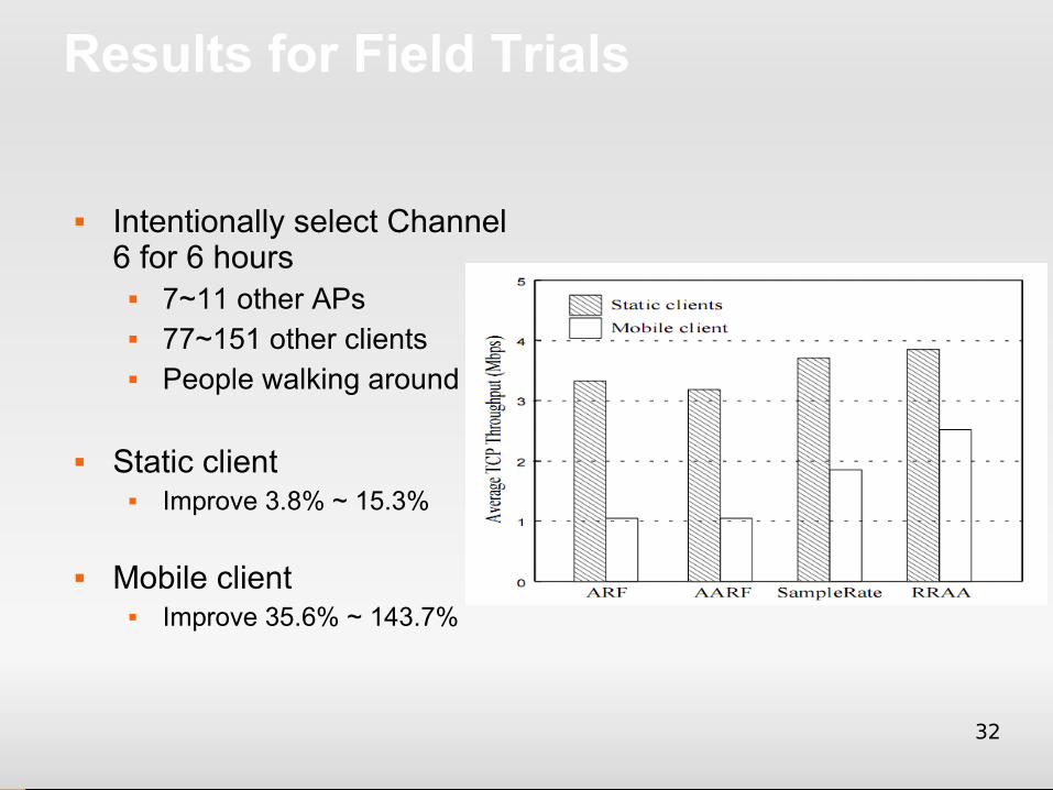
Results for Field Trials
Intentionally select Channel 6 for 6 hours
7~11 other APs 77~151 other clients People walking around
Static client Improve 3.8% ~ 15.3%
Mobile client Improve 35.6% ~ 143.7%
33
Summary
Critique on five existing design guidelines All have problems in practice
Design RRAA Short-term statistics Adaptive RTS
RRAA outperforms other rate adaptation designs in all cases
34
Ongoing work
A refined design Use both frame statistics and PHY metrics to infer
collision losses zero communication overhead !
Techniques to handle clients with light traffic Techniques to work with power control Techniques to work with carrier sensing tuning
Used in latest Meru product (AP 200) releases, performs better than Cisco (Aironet 1200) AP by 32%~212%
35
Discussion
The good NO simulation. Real experimental data Actual hardware implementation. Used in a
commercial product! Goes against conventional wisdom
36
Discussion
The not so good The choice of α and β is still fairly ad-hoc No details on ewnd estimation Mobility experiments have a single mobile
client How important is mobility in practice?