rockfall mitigation workshop - · pdf fileexperienced people currently in place toople...
TRANSCRIPT

RockfallRockfall MitigationMitigation WorkshopWorkshop
l
l
i
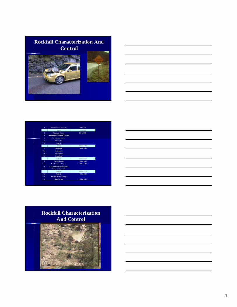
Rockfall Characterization AndRockfall Characterization And ControlControl
1600 to 16301600 to 1630Open ForumOpen Forum1010
Rockfall Hazard RatingsRockfal Hazard Ratings9e9e
1445 to 16001445 to 1600AnalysisAnalysis9d9d
1430 to 14451430 to 1445BREAKBREAK
Anchored Wire MeshAnchored Wire Mesh8c8c
Wire and Cable Mesh DraperyWire and Cable Mesh Drapery8b8b
1300 to 14301300 to 1430Flexible Rockfall FencesF exible Rockfall Fences8a8a
1300 to 16301300 to 1630Current EventsCurrent Events88
1200 to 13001200 to 1300LUNCHLUNCH
ProtectionProtect on7c7c
StabilizationStabilization7b7b
AvoidanceAvoidance7a7a
1015 to 12001015 to 1200MitigationMitigation77
1000 to 10151000 to 1015BreakBreak
AnalysisAnalysis66
MonitoringMonitoring55
Site CharacterizationSite Characterization44
Recognition of Rockfall HazardsRecognition of Rockfall Hazards33
830 to 1000830 to 1000Types and CausesTypes and Causes22
825 to 830825 to 830BreakBreak
800 to 825800 to 825Intro/Executive SummaryIntro/Executive Summary11
Rockfall CharacterizationRockfall Characterization And ControlAnd Control
1
–
–
–
–
–
–
–
Executive SummaryExecutive Summary
With a SystematicWith a Systematic AApproachpproach to wto wee wwillill – IImmprove Public Safetyprove Public Safety
– Increase MobilityIncrease Mobility
– ReducReduce Tort Liabe Tort Liability Exposureility Exposure
Improve Public SafetyImprove Public Safety
RReeduce overall costs becauseduce overall costs because wwee wwill haveill have a systea systemmatic approach stateatic approach statewwideide
ExperiencedExperienced pepeople currently in place toople currently in place to solve the problsolve the probleemm
Increase MobilityIncrease Mobility
Through SyThrough Systestemmatic approaatic approachch – Right fix first timRight fix first timee
– Identify problemIdentify problems before theys before they becbecoommee problemproblemss
– Every rockfall imEvery rockfall impairs traffic flowpairs traffic flow
– ReducReduce incie incidentsdents of rockfall you inof rockfall you increascreasee mmobilityobility
2

–––– – -
Reducing Tort LiabilityReducing Tort Liability ExposureExposure
This systemThis system reduces threduces that exposat exposureure
Effective syEffective systemstem
ProvenProven
Reducing Tort Liability ExposureReducing Tort Liability Exposure Improve Public SafetyImprove Public Safety
Between JanuarBetween Januaryy 1,1, 19199944 and Dand Deecembercember 3131,, 20200077 there have been seventythere have been seventy (70) rock(70) rock cases filed agaicases filed against Caltnst Caltransrans thathatt have beenhave been resolved.resolved.
Of the seventyOf the seventy (70) cases,(70) cases, there werethere were – eighteen (1eighteen (18)8) wwrroonngful deaths,gful deaths, – ffiivvee (5(5) q) quuadadrriipplleeggiicc iinnjurjuriieess,, – twotwo (2(2) pa) paraplegicraplegic injuries,injuries, – eeiigghhtt (8(8) b) brraiain in innjurjuriieess – and the remainingand the remaining thirtthirtyy-threethree (3(33)3) ccaases had ases had a
vavarietriety ofy of lesselesser inr injjuuries.ries.
Reducing Tort Liability ExposureReducing Tort Liability Exposure Improve Public SafetyImprove Public Safety
Thirty two (32) ofThirty two (32) of the cases werethe cases were dismissed ordismissed or resulted in aresulted in a defense verdict withdefense verdict with Caltrans payingCaltrans paying zero.zero.
3

FiftyFifty-two million, one two million, one hundred and twentyhundred and twenty-eight thousand dollars eight thousand dollars ($52,128,000).($52,128,000).
–
–
–
“ ”
-
Reducing Tort Liability ExposureReducing Tort Liability Exposure Improve Public SafetyImprove Public Safety ThirtyThirty eighteight (3(38)8) ccaasesses
resulted inresulted in eithereither aa settlement orsettlement or aa judgment wijudgment with ath a combined pacombined payoutyout ofof
--
Rockfall presents theseRockfall presents these problems for the motoristsproblems for the motorists
– RoRockck hhittingitting carcar
– Car avoiCar avoididing rng roockck runnirunninngg ofofff road orroad or hhittinittingg carcar
– Car hCar hittinittingg rockrock
What is a RockfallWhat is a Rockfall
“RockfRockfaallll” is theis the mmovemovemeentnt of rockof rock ofof
from a cliff orany sizeany size from a cliff or other slopeother slope that isthat is soso steep the msteep the maassss continues to mcontinues to moveove downdown slope.slope. MovemMovemeent mnt maay be byy be by frefreee-falling, bfalling, bouncouncing,ing, rolling orolling orr sliding.sliding.
4

–
–
–
–
–
Train Train
AwarenessAwareness
First ResponseFirst Response
Introductory courseIntroductory course
Foundation to Begin a Foundation to Begin a Systematic ApproachSystematic Approach
Call Support Call Support PersonnelPersonnel– Subject expertsSubject experts
RockfallRockfall
– VerVeryy Rapid toRapid to ExtreExtremmelelyy RapiRapidd EventEvent
– 1010 ffeet peeet per secor secondnd and highand higherer
– TRB 247 LandslidTRB 247 Landslideess AnalAnalyyssis and Contris and Controoll 1996 Velocit1996 Velocityy ClasClasss 7.7.
Executive SummaryExecutive Summary
– TherTheree araree SSppececiaialliiststs ws whhoo arare tre traaiinneedd in tin thhe de diiscsciipplliinnee ofof rroockfckfaallll
– LLiikeke allall didissccipiplinlineess toto ddoo tthhiiss wowork rerk requiquireress exexperperiieenncece aanndd prpracacttiicece whwhiicchh ccaann onlonly bey be acqacquuiirreed byd by ddooiinng prg proojjeeccttss ununderder tthhee ttuutetelalage ofge of eexxppeerriienencceedd pprracactitititiononeerrss aanndd attatteennddining tg trraaiininingng clclassesasses..
ObjectivesObjectives in this course forin this course for GeotechGeotech
–
5

-
Project ManagemenProject Managementt
AwarenesAwareness of rockfall issuess of rockfall issues
DevDeveelop planslop plans and speand speccss
TiTimmeeline of projectsline of projects
ResResourcesources
Purpose aPurpose andnd NeedNeed
MaintenanceMaintenance
First responseFirst response
AwarenesAwarenesss
Reduce WorkloadReduce Workload - Cost SaviCost Savingsngs
HHeelp Projlp Project initiatect initiatiionon
HHeelp identify the problemlp identify the problemss
Provide HistorProvide Historyy
6

ConstructionConstruction
Rapid resRapid responseponse
AwarenesAwarenesss
Educate oEducate onn ProProductsducts
SolutionsSolutions
ResResource to solource to solvve problee problemmss
There is a process!There is a process! A systematic approachA systematic approach TypesTypes
RatingsRatings
InvestigatInvestigationion
InstruInstrummeentationntation
AnalysisAnalysis
MitigatiMitigatioonn
ConstructionConstruction
7

ROCKFALL SOURCES AND CAUSES
• Rockfall occurs on slopes steeper than 33° (1.5:1) that have loose rock on the slope surface. Gravity assisted by other mechanisms causes loose rock to move down slope. The following is a brief review of rockfall sources and causes.
ROCKFALL SOURCES
• Fractured Rock – Internal fracture
orientations influence slope
stability
• Blocky Deposits – Weak Or No Matrix
• Colluvium
• Talus
• Volcanic Ash Deposits
• Glacial Till
• Others
ROCKFALL SOURCES
FRACTURED ROCK • Common Failure Types
– Planar – Wedge – Toppling – Buckling – Circular
• Localized Failures – Discontinuous fracture planes limit
failures to a few blocks
• Deeper Seated Failures – More continuous fracture planes
causes some or all of slope to fail
1

ROCKFALL SOURCES
FRACTURED ROCK
– Adversely Oriented Fractures
– Orientation Steeper Than Friction Angle
ROCKFALL SOURCES
FRACTURED ROCK
– Differential Erosion
– Decomposition / Weathering
FRACTURED ROCK - Rockfall Sources
SLOPE FAILURES • Slow moving
slides
• Toe oversteepens and fails
• The mass breaks apart and becomes rockfall
2

t
FRACTURED ROCK - Rockfall Sources
DEEP SEATED FAILURES
• Dormant slides – Marginally stable slide
mass occasionally fails as rockfall in unusual storm events
• Reactivating – Rockfall can be the first
indicator that a dormant slide is reactivating Rockfall Chu es
Rockfall Sources
BLOCKY DEPOSITS
– Many deposits at angle of repose
– Raveling
– Boulder Fall
Rockfall Sources
BLOCKY DEPOSITS
• Differential Erosion
• Weak Matrix
3
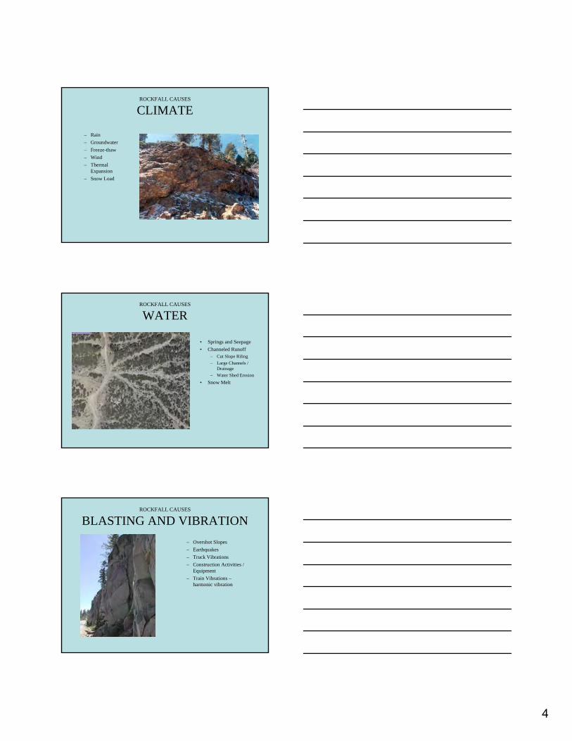
ROCKFALL CAUSES
CLIMATE
– Rain
– Groundwater
– Freeze-thaw
– Wind
– Thermal Expansion
– Snow Load
ROCKFALL CAUSES
WATER
• Springs and Seepage
• Channeled Runoff – Cut Slope Riling
– Large Channels / Drainage
– Water Shed Erosion
• Snow Melt
ROCKFALL CAUSES
BLASTING AND VIBRATION
– Overshot Slopes
– Earthquakes
– Truck Vibrations
– Construction Activities / Equipment
– Train Vibrations – harmonic vibration
4

ROCKFALL CAUSES
NATURAL AND EXCAVATED SLOPES
– Relaxation of the Rock Mass
– Slopes Age
ROCKFALL CAUSES
OUTSIDE INFLUENCES
– Burrowing Animals
– Tree Roots
– Wild Animals
– Humans
– Fires
5

Recognition of Rockfall Hazard
• Maintenance • Legal • Citizens • Construction • CHP • TASAS Traffic
Accident Surveillance Analysis System -Accident History
• Ethically
Recognition of Rockfall Hazard
• Maintenance – On the highway daily
observing slopes
– Perform Rock patrols in mountainous regions
– Typically first CT responders to accidents involving rockfall
Recognition of Rockfall Hazard
• Legal – Are aware of pending
litigation for accidents involving rockfall.
1

Recognition of Rockfall Hazard
• Citizens – Reports directly from
highway drivers to the District Office or local maintenance yard of areas where rockfall has occurred.
– Reports from citizens that live adjacent to an area where a rockfall has occurred.
Recognition of Rockfall Hazard
• Construction
Recognition of Rockfall Hazard
• CHP – Respond to accidents
involving rockfall.
– Receive public complaints about potential hazardous conditions along the highway.
– Patrol sections of the highway and may have concerns of their own
2

Recognition of Rockfall Hazard
• TASAS Traffic Accident Surveillance Analysis System - Accident History
Method of Evaluation of Rockfall Hazard
• Risk Based Assessments – Historical and literature review of recognition approaches – including
aerial and ground based methods (including photography, remote sensing, LIDAR, GIS, and creating a rock slope data base.
• Hazard Rating-CT
Rockfall Hazard Rating Systems Tool to Prioritize
• Rock slope rating procedures – Basic concepts
– Historical development
– Rock slope inventory and database management
– Accommodating climate regimes
– Maintenance program documentation
3

Inventories and Hazard Ratings Systems
• The Rockfall Hazard Rating System – RHRS Rockfall Hazard Rating System (Nationally
Funded Pooled fund study) – NY DOT Rock Slope Rating Procedure – Penn DOT Geotechnical Problem Inventory Program – Colo Geo Survey Site Specific Hazard Rating System – CDOT – Tenn DOT – AZ DOT – Golder And Assoc. – Hong Kong
Caltrans Adopted Method – RHRS Rockfall Hazard Rating System
• In order to achieve conformity and consistency within the Department when the occasion requires a quantitative ranking of rockfall generating slopes it is Geotechnical Services policy that the Rockfall Hazard Rating System (RHRS) be used as the standard.
RHRS Rockfall Hazard Rating System
• The development of RHRS was funded through a HPR pooled fund study of which Caltrans was a contributor and served on the Technical Advisory Committee (TAC). Caltrans Engineering Geology staff not only served as technical advisors but also evaluated the systemfor statewide application. Caltrans staff has used RHRS as a method of prioritizing rockfall mitigation projects since it was published in 1990.
4

RHRS Field Rating
• Field Rating utilizing RHRS – A quick assessment of
rockfall concerns can be made in the field utilizing a simple points rating system assigning either 3,9,27 or 81 points for each condition that needs to be recorded to complete a RHRS study.
• Final Rating Utilizing RHRS
RHRS Final Rating
– Uses a combination of data collected in the field and supporting data collected in the office setting.
– Some categories are quantified utilizing mathematical equations.
RHRS Components of Rating System
– Slope Height
– Ditch Effectiveness
– Average Vehicle Risk
– Percent of Decision Site Distance
– Road width Including Shoulders
– Geologic Character
– Block Size/Quantity of Event
– Climate and Presence of Water on Slope
– Rockfall History
5

RHRS Components Slope Height
• Slope height is the maximum vertical height of the slope in which rockfall can occur.
RHRS Components Ditch Effectiveness
• Effectiveness –The key word is EFFECTIVENESS
No matter what type of ditch or catchment area it is, this is a rating of how well the area contains the rocks that come down the slope and prevents them from reaching the traveled way
RHRS Components Average Vehicle Risk - AVR
• AVR= (ADT X (SD/5280) / 24) / SL X 100
• Average Vehicle Risk take into account the following three items.
• Average Daily Traffic (ADT)
• Slope Distance (SD)
• Speed Limit (SL)
6

RHRS Components Percent of Decision Site Distance
• Percent of Decision Site Distance is the required site distance for a given speed divided by the actual site distance.
– Sight distance should be measured in the field approaching the rockfall location from both directions and the shortest distance obtained should be utilized in the equation.
– Table from Section 201.7 Caltrans Highway Design Manual, 6th edition.
RHRS Components Road width Including Shoulders
• This is obtained by measuring the paved area.
• Why it is important? – This identifies where a
vehicle may swerve to avoid a rockfall.
RHRS Components Geologic Character
• Case 1 - Structural Condition – Typically caused by
adverse joint sets, fractures and bedding planes.
7

RHRS Components Geologic Character
• Case 2 Differential Erosion – When competent rock
blocks are contained within a weaker matrix material that is more susceptible to erosion.
– Matrix can be comprised of soil as in glacial till.
RHRS Components Block Size/Quantity of Event
• A rockfall where quantity would be described in block size.
• A rockfall where quantity could be described in either block size or volume.
RHRS Components Climate and Presence of Water
• RHRS divides Climate and Presence of Water into three areas – Precipitation
– Ground water
– Freeze thaw
8

Rockfall History RHRS Components
• RHRS divides rockfall history in to four categories
– Few Falls – Occasional Falls – Many Falls – Constant Falls
RHRS
• It is important to maintain the statewide data base of rockfall ratings in the same scoring system and language. This is the language of rockfall and allows practitioners statewide to compare projects, evaluate sites, and make decisions.
9

Site Characterization
• The three components of many rock-fall hazard assessments are – a determination of the relative susceptibility of
rock outcrops to rock-fall initiation,
– identification of travel paths of potential rock falls,
– and an evaluation of the depositional zone (sometimes referred to as rock-fall runout).
Site Characterization
• Regionally
• Globally
• Locally
Site Characterization
• You have to get out of the car
• Experience
• Training
• Field Partner
1

Site Characterization
• Is there evidence of rockfalls in the area? Although a site is below a bluff or steep slope it does not mean there is rockfall activity. Typically there will be field evidence such as impact marks, broken trees or individual rocks or rock accumulations scattered throughout the area. But there also may be no rocks on the slope indicating rocks are not traveling far from the base of the slope or falling at all.
Site Characterization
• Its OK to not have a rockfall problem!
Site Characterization
• Literature Review
• Climate
• Maintenance History
• Rock Structure Implications
• Photo Interpretation
• Geologic Field Mapping
• Rockfall Characteristics
• ALL Part of the DPGR and GDR
2
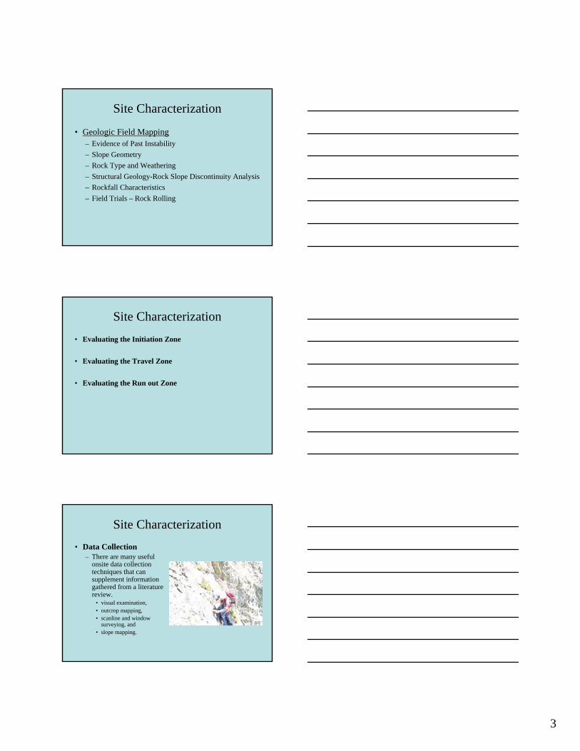
Site Characterization
• Geologic Field Mapping – Evidence of Past Instability
– Slope Geometry
– Rock Type and Weathering
– Structural Geology-Rock Slope Discontinuity Analysis
– Rockfall Characteristics
– Field Trials – Rock Rolling
Site Characterization
• Evaluating the Initiation Zone
• Evaluating the Travel Zone
• Evaluating the Run out Zone
Site Characterization
• Data Collection – There are many useful
onsite data collection techniques that can supplement information gathered from a literature review.
• visual examination, • outcrop mapping, • scanline and window
surveying, and • slope mapping.
3

Site Characterization
• Evaluation of the Travel Paths – slope height
– topographic profile
– variable slope angles
– potential launch points
– rock type variations
– soil cover
– vegetative cover
– potential runout areas
– impact zones.
Site Characterization-Travel Paths
Site Characterization
• Evaluation of the Travel Paths
– They also largely affect the mode of travel:
• Rolling • Bouncing • free falling.
– Existing impact locations onstructures, trees or otherimpediments allow rudimentaryestimates of bounce heights and launch points.
– Slope height, angle and thefrictional resistance ultimatelydetermine the energy of the rockmotion.
4

Site Characterization
• Depositional Zones – Analyzing rockfall
deposits involves reviewing fallen rock material in the runout zone near the base of the slope as well material deposited on the slope.
– Information such as the size, density, and shape of the projectile rocks should be observed.
Site Characterization
– Additionally, the mode offailure and cause of failure should be identified.
– Maintenance reports andeyewitness accounts are also good information sources.
– For many of thetransportation agencies, maintenance records of rockfall on roadway and ditches and can be the best source of identifying thelocations of reoccurring rock fall.
Site Characterization
– Single source area or random source areas
– What size rock typically reaches the base of the slope
– Max bounce height
– Maximum velocity/energy
5

Site Characterization
– Nature of event single or group of rocks
– Hit other rocks and destabilize those rocks
– Rock Avalanche
6

Instrumentation
Rockfall Investigation
Monitoring • Visual Inspection
• Video CAMs
• Direct Crack Monitoring
• Remote Monitoring
• Tilt Movement
• SSR (Slope Stability Radar)
• Indirect Monitoring – IMMS
Monitoring
• Visual Inspection – Check bedding and joint
orientation.
– Review the rock type at the site.
– Review surroundings for signs of rockfall activity
• Broken limbs
• Holes in pavement
• Damage to structures
1

Monitoring
• Video CAMs
Monitoring
• Direct Crack Monitoring
Monitoring
• Tripwire at brake ringsIf an event occurs, the brake rings willcontract and the tripwire will be torn outof the Impact Sentinel Unit which will then trigger the alarm.The alarm signal is transmitted wirelessly from the sensors to the datalogger where it is evaluated and then forwarded to the person in charge via Text Messaging or Radio Data Communications.
• Can be used permanently ortemporarilyImpact Sentinel can be used permanently, for instance, in remote areas or temporarily, for instance, tohelp secure construction sites.
2

Monitoring
• Tilt Movement
Rockfall Investigation
Monitoring • SSR
Single rock fall during rain
Alarm at 5mm provided 1 hour of
warning
Rockfall Investigation
Monitoring • Rock Patrols
3

Indirect Monitoring (IMMS)
• Utilizing Maintenance work order records to monitor Rockfall Problems on a local or Statewide basis.
4

Rockfall Analysis
• Selection and design of effective protection measures requires the ability to predict rockfall behavior.
Rockfall Analysis
• Consider
– Globally
– Locally
Rockfall Analysis
• Rockfall behavior is defined in three phases: – an initiation zone,
– a travel zone,
– and the depositional zone.
• At the initiation point a rock has potential energy that becomes kinetic energy that is dissipated as the rock bounds down slope and eventually comes to rest.
1

Rockfall Analysis
• In many cases, for example, when dealing with boulders on the top of slopes, the rockfall hazards are obvious.
• In other cases rockfall hazards are not so obvious as in the case where rock failure occurs when a block is suddenly released from an apparently stable face in the surrounding rock mass.
Rockfall Analysis
• Initiation Zone – Rock Mass
• Kinematics
– Soil • Method of Slices
– Transitional Materials • Slices
• Erosion Rates
Rockfall Analysis
• Analytical solutions to determine travel path and run out zones are determined by – computer simulations
where rockfalls are modeled
– or from empirical data where rocks are rolled down a slope.
2

Rockfall Analysis
• The results of these analyses, together with geological data on block sizes and shapes, can be used to determine the potential of a rockfall occurring and estimate the dimensioning of mitigation such as the height of a barrier or width of a catchment ditch.
Rockfall Analysis
• For very weak rock • Transitional Materials where the intact – Residual Soils
material strength is of the same magnitude as – Colluvium the induced stresses, the structural geology may – Talus not control stability, and classical soil mechanics
– Other Degradable principles for slope Materials stability analysis apply.
Rockfall Analysis
• Types Of Rock Slope Failures – Planar failures are
governed by a single disconti-nuity surface dipping out of a slope face.
– Rock Pack
– Rock Science
3

Rockfall Analysis
• Types Of Rock Slope Failures – Wedge failures involve
a failure mass defined by two discontinuities with a line of intersection -that is inclined out of the slope face.
– Rock Pack
– Rock Science
Rockfall Analysis
• Types Of Rock Slope Failures – Toppling failures
involve slabs or column, rock defined by discontinuities that dip steeply into the slope face.
– Rock Pack
– Rock Science
Rockfall Analysis
• Types Of Rock Slope Failures – Circular failures occur
in rock masses that are either highly fractured or composed of material with low intact strength.
– Slope W
– STABL
4

PE
Rockfall Analysis
• There are two principle methods of analyzing rockfall travel and run out zone. – One is to perform field tests whereby rocks are
rolled and the behavior of the falling rock is observed for different slope characteristics.
– The second is to do a computer simulation. This is typically done using the various computer programs developed for that purpose.
Rockfall Analysis
ENERGY • Kinetic Energy (KE)
• Foot tons
• Kilo Joules
– Translational KE
• ½ m2
– Angular KE
• ½ I 2
– Total KE
– ½ m2 + ½ I2
– KE Cannot be greater then
Rockfall Analysis
• Mass and Weight
– m= w/g
– (SG rock)( water) = ( rock)
• Velocity
– - distance / time
– = radians / time
5

Rockfall Analysis
• All collisions between macroscopic bodies are inelastic. Total kinetic energy therefore lessens by some amount. The kinetic energy of a system cannot increase without work being done by some outside agent.
• A rockfall on a slope is inelastic. In any non-perfectly elastic (inelastic) collision, kinetic energy is lost.
• In the case of a rock impacting a slope, the component of kinetic energy parallel to the slope and the rotational energy are attenuated by friction along the slope and collisions with features perpendicular to the slope.
Rockfall Analysis
• The Conservation of Energy principle asserts that in a closed system energy is conserved.
• When an object is at rest at some height, h, then all of its energy is PE. As the object falls and accelerates due to the earth's gravity, PE is converted into KE.
• When the object strikes the ground, h=0 so that PE=0.
Rockfall Analysis
• EMPIRICAL ANALYSIS OF ROCKFALL – Over the years there have been numerous rockfall studies
where rocks have been rolled down slopes for the purpose of understanding rockfall trajectories.
– Some of these tests have been solely for rockfall observation while others have been combined to evaluate the performance of protection systems.
– In every case a unique source of rock rolling data has been collected for various slope characteristics. This information is a valuable guide to practitioners and researchers in understanding rockfall behavior.
6
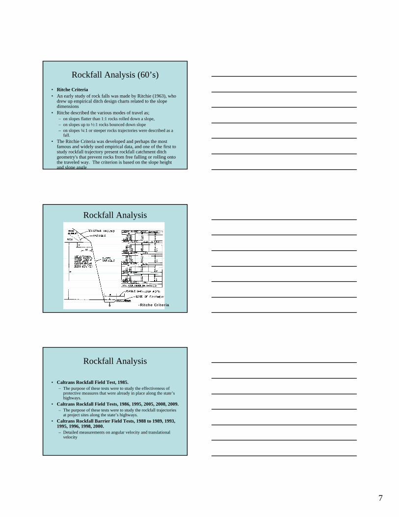
Rockfall Analysis (60’s)
• Ritche Criteria • An early study of rock falls was made by Ritchie (1963), who
drew up empirical ditch design charts related to the slope dimensions
• Ritche described the various modes of travel as; – on slopes flatter than 1:1 rocks rolled down a slope, – on slopes up to ½:1 rocks bounced down slope – on slopes ¼:1 or steeper rocks trajectories were described as a
fall.
• The Ritchie Criteria was developed and perhaps the most famous and widely used empirical data, and one of the first to study rockfall trajectory present rockfall catchment ditch geometry's that prevent rocks from free falling or rolling onto the traveled way. The criterion is based on the slope height and slope angle
Rockfall Analysis
-Ritche Criteria
Rockfall Analysis
• Caltrans Rockfall Field Test, 1985. – The purpose of these tests were to study the effectiveness of
protective measures that were already in place along the state’s highways.
• Caltrans Rockfall Field Tests, 1986, 1995, 2005, 2008, 2009. – The purpose of these tests were to study the rockfall trajectories
at project sites along the state’s highways.
• Caltrans Rockfall Barrier Field Tests, 1988 to 1989, 1993, 1995, 1996, 1998, 2000. – Detailed measurements on angular velocity and translational
velocity
7
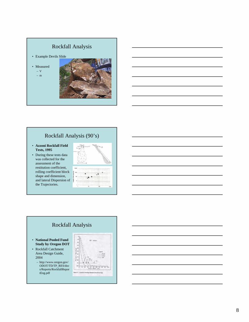
Rockfall Analysis
• Example Devils Slide
• Measured – V
– m
Rockfall Analysis (90’s)
• Azzoni Rockfall Field Tests, 1995
• During these tests data was collected for the assessment of the restitution coefficient, rolling coefficient block shape and dimension, and lateral Dispersion of the Trajectories.
Rockfall Analysis
• National Pooled Fund Study by Oregon DOT
• Rockfall Catchment Area Design Guide, 2004 – http://www.oregon.gov/
ODOT/TD/TP_RES/doc s/Reports/RockfallRepor tEng.pdf
8

Rockfall Analysis • Other rock rolling
tests around the world – CDOT
– Switzerland
– Taiwan
– China
– France
– Germany
– Canada
– Italy
Rockfall Analysis
• Whenever possible, rolling rocks in the field will provide the most accurate information for rockfall analysis.
• Obtaining good test data for rockfall analysis requires careful preparation. – A measurement of the rocks to be rolled is needed
together with a properly prepared test slope.
– And most importantly, film and video equipment should be in place and operational.
Rockfall Analysis
• Field Tests – Test Slope
• Ground based Lidar
– Test Rocks
– Data Collection
– Computer Modeling
9

Rockfall Analysis
Caltrans Field Tests
Rockfall Analysis
• Swiss Field Tests
Rockfall Analysis
• COMPUTER SIMULATION OF ROCKFALL – Computer modeling allows designers and
investigators to observe dozens or even hundreds of simulated rockfall events.
– The 1990’s experienced a renaissance of rockfall computer modeling. These models attempt to predict rockfall behavior and describe rockfall in terms of trajectory and energy.
10

Rockfall Analysis
• COMPUTER SIMULATION OF ROCKFALL – The majority of the models used today are two
dimensional calculating horizontal and vertical movements along a single cross sectional segment.
– Three-dimensional models additionally calculate lateral movement across a slope and although available have yet to achieve wide spread use due in part to the considerable data input requirements.
Rockfall Analysis
• COMPUTER SIMULATION OF ROCKFALL – Most of these rockfall models include a Monte
Carlo simulation technique to vary the parameters included in the analysis. This technique, named after the gambling casinos of Monte Carlo, is similar to the random process of throwing dice one for each parameter being considered.
Rockfall Analysis
• COMPUTER SIMULATION OF ROCKFALL – CRSP – USA
– Rocfall - Canada
– Rockfall - Europe
11

In order to achieve conformity and consistency within the Department when the occasion requires a rockfall computer simulation it is Geotechnical Services policy that the current version Colorado Simulation Program (CRSP) be used as the standard.
Rockfall Analysis
•
Rockfall
Rockfall Analysis
• The development of CRSP was funded through the Colorado Department of Transportation in cooperation with the U.S, Department of Transportation, and Federal Highway Administration. Caltrans Engineering Geologystaff evaluated initial test versions of the program andcontributed rock rolling data to its development
• CRSP is used by most State Departments of Transportation and many countries around the world.FHWA supports and encourages the use of CRSP through Chapter 6 of Rockfall Mitigation manual and the National Highway Institute (NHI) training class (NHI Course No. 13219).
Rockfall Analysis
• The Colorado Rockfall Simulation Program (CRSP) was developed for the purpose of modeling rockfall behavior and to provide statistical analysis of probable rockfall events at a given site.
• The program is based upon field studies of actual rockfalls and upon the principles of physics that apply equations of gravitational acceleration and conservation of energy to describe a body in motion..
12
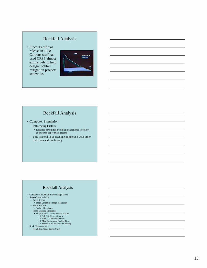
Rockfall Analysis
• Since its official release in 1988 Caltrans staff has used CRSP almost exclusively to help design rockfall mitigation projects statewide.
Rockfall Analysis
• Computer Simulation – Influencing Factors
• Requires careful field work and experience to collect and use the appropriate factors.
– This is a tool to be used in conjunction with other field data and site history
Rockfall Analysis
• Computer Simulation-Influencing Factors • Slope Characteristics
– Cross Section • Slope Length and Slope Inclination
– Slope Surface • Surface Roughness
– Slope Material Properties • Slope & Rock Coefficients Rt and Rn
– 1. Soft Soil Slopes-pictures – 2. Talus and Firm Soil Slopes – 3. Most Bedrock and Boulder Fields – 4. Smooth Hard Surfaces and Paving
• Rock Characteristics – Durability, Size, Shape, Mass
13

Rockfall Analysis
3-Dimensional Simulations CONEFALL Model Others Europe Japan US (the new CRSP)
Rockfall Analysis
• Shadow Angle – The shadow angle is defined by the apex of the slope and
not by the rockfall source area above the slope.
– This is an angle between the horizontal line and the line connecting the highest point of talus and the point where the rocks stop.
– This approach does not require the knowledge of the precise location of each rockfall release, because the rockfall activity is integrated in time by taking into account the largest distance traveled by blocks.
Rockfall Analysis
Shadow Angle
14
Rockfall Analysis
• Shadow Angle – The minimum shadow angle is the smallest shadow angle
of an area.
– Minimum values were given by several authors and are between 22° and 30°. Research in British Columbia came to a conclusion that the shadow angle is at least 27.5°, regardless of rock face height, trajectory length and slope gradient. Where talus slope is rather smooth, researchers suggest lower values (23°-24°).
– The minimum shadow angle should be used only for the first assessment of the rockfall runout distance.
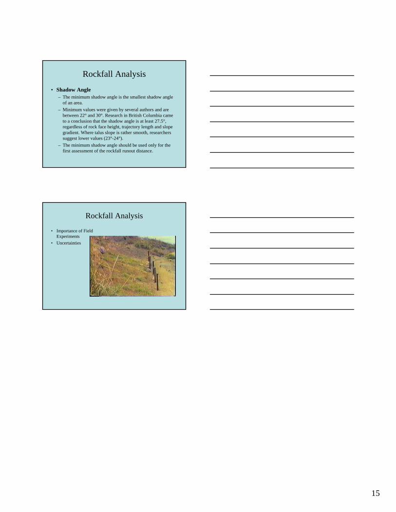
Rockfall Analysis
• Importance of Field Experiments
• Uncertainties
15

ROCKFALL MITIGATION METHODS
ROCKFALL MITIGATION METHODS
• Selection Criteria – Complexity – Effectiveness – Durability – Constructability – Special Expertise – Road Closure/Traffic Restrictions – Environmental Limitations – Aesthetic Impacts – Cost – Maintenance Requirements
ROCKFALL MITIGATION METHODS
• Relocation
• Stabilization
• Protection
• Management
1

Separate the facility from the hazard
• Viaducts/Bridge
• Tunnel
• Realignment
Rockfall Mitigation Methods
RELOCATION
Avoiding the site is sometimes the cheapest and safest long-term
solution to its rockfall problem
Rockfall Mitigation Methods
RELOCATION • Reasons
– Public safety
– Maintenance cost
– Construction safety
– Length of road closures
– No other reasonable alternatives
Rockfall Mitigation Methods
RELOCATION
–
1

RELOCATION - Rockfall Mitigation Methods
VIADUCT/BRIDGE • Elevate roadway to
allow rockfall to pass under structure
• Structure supports must be protected or out of rockfall impact zone
• Move alignment away from slope to create rockfall catchment area
RELOCATION - Rockfall Mitigation Methods
TUNNELS • Avoids rockfall
by moving roadway into hillside
• Tunnel portals must be outside of rockfall impact zone
RELOCATION - Rockfall Mitigation Methods
REALIGNMENT • Move roadway
away from rockfall area
• Sometimes the nearby terrain does not allow realignment
2

RELOCATION - Rockfall Mitigation Methods
CASE HISTORIES • Viaduct/Bridge
– Forest Boundary
– Pitkins Curve
• Tunnel – Devils Slide
• Realignment – Confusion Hill
– Ferguson
• Hybrid – Emerald Bay
VIADUCT CASE HISTORY - Relocation Rockfall Mitigation Methods
FOREST BOUNDARY-Viaduct • Viaduct allows
unstable material to pass under the structure
• Since then at this site there have been no road closures
• No cleanup of rock fall debris required
VIADUCT CASE HISTORY - Relocation Rockfall Mitigation Methods
PITKINS CURVE-Bridge • 1998 traffic was disrupted
for 5 months, $5 million to restore roadway
• 2000 traffic was disrupted for 2 months, $3.4 million to restore roadway
• Since that time the yearly average has been 10 days of road closure and the maintenance cost has been $1 million
3
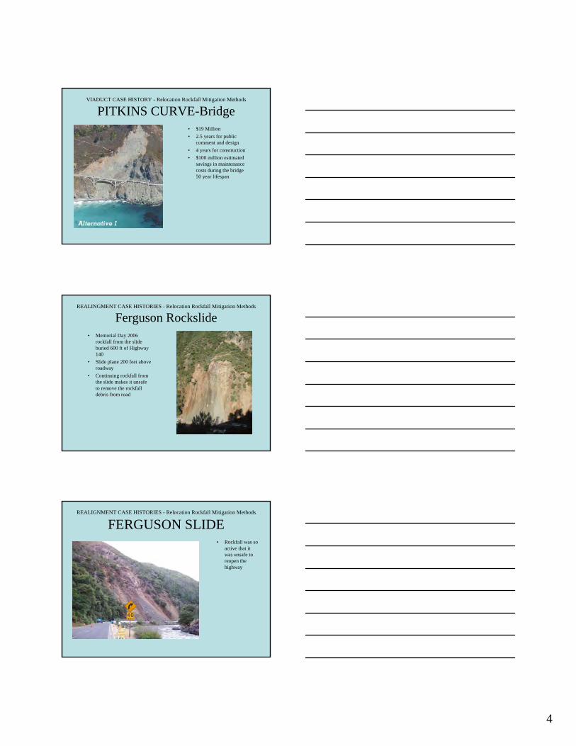
VIADUCT CASE HISTORY - Relocation Rockfall Mitigation Methods
PITKINS CURVE-Bridge • $19 Million
• 2.5 years for public comment and design
• 4 years for construction
• $100 million estimated savings in maintenance costs during the bridge 50 year lifespan
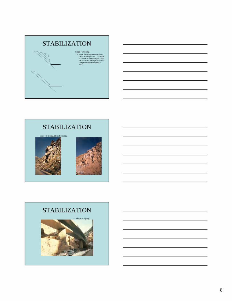
REALINGMENT CASE HISTORIES - Relocation Rockfall Mitigation Methods
Ferguson Rockslide • Memorial Day 2006
rockfall from the slide buried 600 ft of Highway 140
• Slide plane 200 feet above roadway
• Continuing rockfall from the slide makes it unsafe to remove the rockfall debris from road
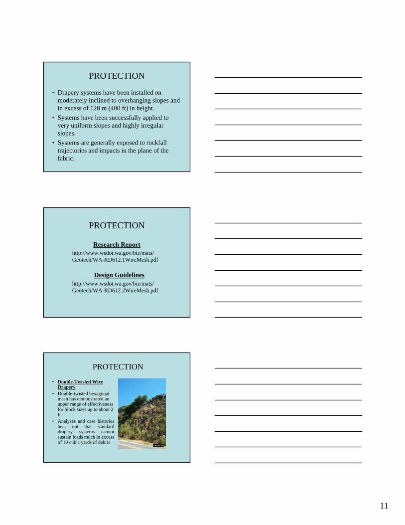
REALIGNMENT CASE HISTORIES - Relocation Rockfall Mitigation Methods
FERGUSON SLIDE • Rockfall was so
active that it was unsafe to reopen the highway
4

REALIGNMENT CASE HISTORIES - Relocation Rockfall Mitigation Methods
Ferguson Rockslide • One of the proposed
alternative alignments would be a 2200 ft long tunnel
• Single bore two lane • Would require lighting
and ventilation • $230 Million • Geotechnical
investigation would take 1 year
TUNNEL CASE HISTORIES - Relocation Rockfall Mitigation Methods
DEVILS SLIDE • Long history
(since it was built in the ’40’s) of rockfalls, slides and road closures
• Closed for 158 days in 1995
• $3 million to repair roadway
TUNNEL CASE HISTORIES - Relocation Rockfall Mitigation Methods
DEVILS SLIDE • Scarps produce
rockfalls
• Individual blocks are up 6 feet in diameter
• Storms and earthquakes cause rockfalls
5

TUNNEL CASE HISTORY - Relocation Rockfall Mitigation Methods
DEVILS SLIDE • Years of public
input and engineering work
• Site will be bypassed with two inland tunnelsRockfall
Areas
TUNNEL CASE HISTORY - Relocation Rockfall Mitigation Methods
DEVILS SLIDE • It will cost $250
million
• Twin 30 foot diameter bores
• 4,200 foot long
• 1,000 foot long bridge
• On-site Operations and Maintenance facility
• Construction will take 5 years
REALIGNMENT CASE HISTORIES - Relocation Rockfall Mitigation Methods
CONFUSION HILL • Maintenance cost
was $33 million for the last ten years
• Over 100 days of road closures in 2005
6

REALIGNMENT CASE HISTORIES - Relocation Rockfall Mitigation Methods
CONFUSION HILL • Five alternative
alignments
• Common Elements – Two Bridges
– Connecting Cut
REALIGNMENT CASE HISTORIES - Relocation Rockfall Mitigation Methods
CONFUSION HILL • One year was
required to obtain necessary permits for this project from other agencies
• FHWA approved emergency relief funds
• Design and Geotechnical work took two years
REALIGNMENT CASE HISTORIES - Relocation Rockfall Mitigation Methods
CONFUSION HILL • Project cost will
be $65 million
• Construction will require 3 years for completion
7

HYBRID CASE HISTORIES - Relocation Rockfall Mitigation Methods
EMERALD BAY • Erosion of
glacial till caused rockfall
• In the mid 80’s a project that included a minor realignment was completed
HYBRID CASE HISTORIES - Relocation Rockfall Mitigation Methods
EMERALD BAY • A viaduct was used to
realign the roadway out away from the slope
• A concrete retaining wall was used to create a rockfall catchment area
• The catchment area requires periodic
cleaning
Avoidance Mitigation Selection
Summary of Engineered Mitigation Measures • Tunnels
– Purpose: Avoids road hazards by moving the roadway inside the rockmass away from external rockfall forces.
– Limitations: Hazards associated with traffic in confined space. Longtunnels require lighting and special ventilation. Expensive.
• Realignment – Purpose: Full road realignment or facility relocation to move away
from rockfall area. – Limitations: Often the old road must be maintained for existing access.
Commonly there is limited space for this option. Expensive.
• Elevated Structures – Purpose: Used to span the anticipated rockfall paths allowing rockfalls
to pass beneath. – Limitations: The structure must completely span the active area to
avoid being damaged by rockfalls. Expensive.
8

STABILIZATION – Rock anchors and strands – Rock Dowels/ Shear Pins – Shotcrete, Gunite and Mtn. Grout – Anchored Mesh – Cable Lashing – Buttressing – Retaining Walls – Rock Slope Protection – Drainage – Dental Work – Polyurethane Resin (PUR) – Slope sculpting/slope flattening
STABILIZATION – Rock anchors and strands
STABILIZATION – Rock Dowels
1

STABILIZATION – Shear Pins/Dowels
STABILIZATION – Shotcrete and Gunite
STABILIZATION – Mountain Grout
2

STABILIZATION
– Anchored Mesh – Caltrans utilizes double twisted
wire mesh and cable nets in anchor wired mesh installations.
STABILIZATION
– Anchored Mesh
STABILIZATION – Cable Lashing
3

STABILIZATION – Cable Lashing
STABILIZATION – Buttressing
STABILIZATION
– Buttressing
4

STABILIZATION – Buttressing
STABILIZATION – Retaining Walls
STABILIZATION – Rock Slope Protection
5

STABILIZATION – Rock Slope Protection
STABILIZATION
– Drainage
STABILIZATION – Drainage
6

STABILIZATION – Dental Work
STABILIZATION – Polyurethane Resin Injection
(PUR)
STABILIZATION – Slope Flattening
Rockfal
l Zone
HWY
CutSlope
Configu
ration
Catchment Area
Disposal Fill
7
STABILIZATION – Slope Flattening
• Slope flattening does not always mean leveling an area. It may be as simple as decreasing the slope ratio to match appropriate planes that prevent the movement of rock.
STABILIZATION – Slope Flattening/Slope Sculpting
STABILIZATION – Slope Sculpting
8

AFTER
STABILIZATION • Scaling
– Scaling is the removal ofloose and marginally stable rock from a slope face, utilizing hand methods
– Scaling is considered a temporary stabilization technique when performed on a routine basis can be utilized for long termstabilization.
SCALING
SCALING and TRIM BLASTING
BEFORE
9

Scaling
• Should be done by experienced contractors – Proper Gear
• Mobile, quick and safe
– Understand Rockfall • Do not do excessive scaling
– Right Tools • Right tool for the right job
– Air bags, light scaling bars, hydraulic jacks
– Appropriate Experience • Many State DOT’s have experience requirements in their
specifications.
STABILIZATION • When it comes to slope stabilization it is not a
one technique fits all slopes.
• Many different techniques maybe utilized in conjunction with one another to stabilize slopes.
• Requires little to no maintenance effort after completion.
STABILIZATION Mitigation Selection
Summary of Engineered Mitigation Measures • Removal: • Scaling
– Purpose: Removal of loose rock from slope by means of hand tools and/or mechanical equipment. Commonly used in conjunction with most other design elements.
– Limitations: A temporary measure that usually needs to be repeated every 2 to 10 years as the slopeface continues to degrade.
• Rock Removal/ Blast Scaling – Purpose: Removal of loose rock or large rock blocks from slope by means of blasting or chemical
expanders. – Limitations: Damage from fly rock and rockfall, and possible undermining or loss of support by key-
block removal. • Trim Blasting
– Purpose: Used to remove overhanging faces or protruding knobs that may act as launch features on a slope.
– Limitations: Difficulties with drilling, debris containment, and safety. • Re-sloping
– Purpose: Cutting the rock slope at a flatter angle to improve slope stability and rockfall trajectories. – Limitations: May have right-of-way or environmental issues.
10

STABILIZATION Mitigation Selection
Summary of Engineered Mitigation Measures • Reinforcement 1/2: • Dowels
– Purpose: Untensioned steel bars/bolts installed to increase shear resistance and reinforce a block. Increases normal-force friction once block movement occurs.
– Limitations: Passive support requires block movement to develop bolt tension. Slope-access difficulties.
• Shear Pins – Purpose: Provides shear support at the leading edge of a dipping rock block or slab using grouted steel
bars. – Limitations: Cast-in-place concrete needed around bars to contact leading edge of block. Access
difficulties. • Rock Bolts
– Purpose: Tensioned steel bars/bolts used to increase the normal-force friction and shear resistancealong potential rock-block failure surfaces. Applied in a pattern or in a specific block.
– Limitations: Less suitable on slopes comprised of small blocks. Difficult to access slope. • Shotcrete
– Purpose: Pneumatically applied concrete requiring high velocity and proper application to consolidate.Primarily used to halt the on-going loss of support caused by erosion and spalling. Also helps retain small supporting rock blocks.
– Limitations: Reduces slope drainage. Can be unsightly unless sculpted or tinted. Wire mesh or fiber reinforcement required. Needs a minimum 2-inch (5-cm) thickness to resist freeze/thaw. Quality and durability are very dependent on nozzleman skills.
STABILIZATION Mitigation Selection
Summary of Engineered Mitigation Measures • Reinforcement 2/2: • Buttresses
– Purpose: Provide support to overhanging rock or lateral support to rock face using either earth materials, cast concrete or reinforcing steel.
– Limitations: Height limitations. May form a roadside hazard and be unsightly. • Cable Lashing
– Purpose: Anchored, tensioned cable(s) used to strap a rock block in place. May be used in conjunctionwith cable nets or wire mesh. Also used as a temporary support during rock-bolt/dowel drilling activities.
– Limitations: Due to slope and/or block geometry, typically movement must occur for full cableresistance to develop.
• Whalers/Lagging – Purpose: Anchored beams or steel straps used to hold rock blocks in place between bolt locations.
Also used as a temporary measure to provide support during rock-bolt/dowel drilling activities. – Limitations: Unsightly as a permanent application. Movement must occur for full
tensioning/resistance to develop. • Anchored wire mesh/cable nets/ high tensile strength steel mesh
– Purpose: Free-draining, pinned/anchored-in-place nets or mesh. Used to apply an active retention force to retain rocks on a slope.
– Limitations: May form pockets of loose rock as rockfall debris accumulates. Can be difficult to clean out.
STABILIZATION Mitigation Selection
Summary of Engineered Mitigation Measures • Drainage:
– Weep Drains • Purpose: Reduces water pressures within a slope using
horizontal drains or adits. Commonly used in conjunction with other design elements.
• Limitations: Difficult to quantify the need and verify the improvements achieved.
11

PROTECTION
• The application of protection measures inherently accepts the occurrence of rockfalls and strives to mitigate the associated hazard by – Stopping
– Controlling
– Deflecting.
Rock Net
Rock Net
Rockfall Source
PROTECTION
• Conditions that typically warrant protection measures include: – rockfall source areas that
lie beyond boundaries of the facility
– aerial extent or nature of the source area is impractical or excessively costly to stabilize or,
– not practical or excessively costly to relocate the facility to avoid the hazard.
PROTECTION
• Protection measures are inherently passive systems. – Provide a barrier
– control the trajectory
– reduce energy
– provide a catchment
• The most common protection measures include: – catchment areas
– barriers and fences
– draped slope protection
1

PROTECTION
• Protection measures can often be – more cost-effective,
– involve simpler construction,
– be constructed within the boundaries of the facility,
– And result in less environmental impacts.
• For these reasons, protection measures are probably more widely applied for remedial rockfall mitigation than stabilization and avoidance measures.
• Protection measures, however, are not the panacea for all rockfall hazards.
PROTECTION
• Flexible • Rigid – Cable Nets
– Rock Sheds – Wire fences – Timber Walls – Wire Drapery – Concrete Walls – Cable Drapery – Jersey Barrier (K-
rail)
– Earthen Berms and Buttresses
– Catchment Ditches
PROTECTION
• Catchment Ditches • catchment areas are
designed to stop moving rocks before they reach the facility by dissipating their energy on flat or negatively sloped ground.
2

PROTECTION
• Properly designed rock Catchment Ditches will prevent most falling rock from reaching the road.
• There are three general design strategies for catchment ditches:
1. Ritchie ditch (Ritchie, 1963; FHWA, 1989), 2. Rockfall Area Design Guide (Pierson et al.,
2001), 3. and computer modeling and dimensioning.
PROTECTION
• The Ritchie Ditch – incorporates slope height
and inclination to dimension the ditch and provide for a rock protection fence, if needed
• Rockfall Catchment Area Design Guide, 2004 – http://www.oregon.gov/O
DOT/TD/TP_RES/docs/R eports/RockfallReportEn g.pdf
PROTECTION
• Computer modeling – This design approach
would be employed for rock falls generated from irregular natural slopes and compound cut slopes or those that exceed the heights defined in previous design methods.
3

PROTECTION
• Mid Slope Benches – With improved
characterization of rock mass conditions and the use of controlled blasting, many designers dropped their use opting for uniform steep cuts that account for potentially adverse structural control combined with ditches.
PROTECTION
• Barriers – can deflect or contain rockfall, depending on their
location and orientation with respect to the rockfall trajectory.
– function either by being sufficiently stiff to withstand or flexible to attenuate the kinetic energy of the rockfall impact.
PROTECTION
• The most common barriers in North America for permanent applications include: – earthen berms – concrete barriers – structural walls – Fences and draperies
• Mass (m) is the property a body has of resisting any change in its state of rest and is a measure of inertia of the rock body.
4

5
PROTECTION
• Earthen berms and Buttresses – Piled earth
– Fortress buttress
– MSE structure with vertical walls
PROTECTION
• Full scale test of geogrid-reinforced MSE wall with a 10,000 kg mass traveling at approximately 30 m/s demonstrates the high capacity (4500 kJ / 1660 ft-tons of this protection measure
4.8 m
0 .60 m
ste e l m esh fo rm w ork w ith w e lded w ire
1 .2 m
geog rids
70°
ROCKFALL MITIGATION-Protection
Testing
• Concrete barriers are widely applied to improve ditch effectiveness, but all systems have their limitations

PROTECTION
• Structural Walls – Walls incorporate a
variety of structural elements to withstand the often very high impact energy associated with rock falls, while striving to minimize the footprint of the protection structure.
PROTECTION
• Gabions – Rock-filled wire baskets
that can be stacked to form gravity walls and barriers for rockfall protection.
– Gabions also have well demonstrated performance of withstanding high impact energies although their capacity has not yet been well quantified.
PROTECTION
• Rock Sheds – The basic configuration of
a shed consists of a near-horizontal roof covered with a layer of energy-absorbing material
– An alternative configuration consists of an inclined, relatively lightweight roof that directs the rock falls across the shed with little impact force
6

PROTECTION
• Rigid
– Rock Sheds
PROTECTION
• Fences, like nearly all barriers, are used to create a rockfall catchment area. A fence is a structure able to maintain a net on a slope in a position to intercept the highest number of moving rock blocks.
PROTECTION
• The blocks’ stopping involves the fence to deform so that it dissipates the kinetic energy of the block with a suitable safety factor.
Impact ForceForce = Mass x
Acceleration
F = m a
F = m v/t
F= m (2 - 1)/(t2-t1)
Impact
A
B
C D
E
7

•It is a fences flexibility that gives the fence a distinct advantage over all other barriers in terms of costs, design and construction.
PROTECTION
• Flexible Barrier
PROTECTION
• NCHRP 20-7 – Recommended Procedures for the Testing of
Rockfall Barriers-• Switzerland, USA, and European Union
• MEL-Maximum Energy Level • SEL-Service Energy Level • Proof Testing under Ideal Conditions
• Compare Products
• Not a Real World Test
8

PROTECTION
• Why do we test? Buyer Beware
PROTECTION
• Vertical Tests
PROTECTION
• Sliding Cable Tests
9

PROTECTION
• Actual Field Tests – 960 kilo-joules
PROTECTION
• at energy levels below 500 kilo-joules fences stop rocks effectively requiring only annual cleaning and associated minor maintenance.
• Above this energy level maintenance requirements increase but not dramatically until energy levels reach 1000-kilo joules and above.
• At these levels rocks are effectively stopped but maintenance is significant and in some cases replacement is necessary.
PROTECTION
• Drapery Systems – Drapery systems entail only anchoring a mesh along the top
of the slope, allowing rockfalls to occur between the slope and the mesh, and controlling their falls into a containment area at the base of the slope/installation.
10
PROTECTION
• Drapery systems have been installed on moderately inclined to overhanging slopes and in excess of 120 m (400 ft) in height.
• Systems have been successfully applied to very uniform slopes and highly irregular slopes.
• Systems are generally exposed to rockfall trajectories and impacts in the plane of the fabric.
Research Report
Design Guidelines
http://www.wsdot.wa.gov/biz/mats/ Geotech/WA-RD612.1WireMesh.pdf
http://www.wsdot.wa.gov/biz/mats/ Geotech/WA-RD612.2WireMesh.pdf
PROTECTION
PROTECTION
• Double-Twisted Wire Drapery
• Double-twisted hexagonal mesh has demonstrated an upper range of effectiveness for block sizes up to about 2 ft
• Analyses and case histories bear out that standard drapery systems cannot sustain loads much in excess of 10 cubic yards of debris
11

November 2009November 2008with black DTWM
drapery
PROTECTION
• Cable Drapery • Cable nets have proven
effective for block sizes up to about 4 ft
• Analyses and case histories bear out that standard drapery systems cannot sustain loads much in excess of 10 cubic yards of debris
PROTECTION
• The slope on the left in photo (A) was draped in 1992 with little attention to slope interface contact. The center slope was draped in 2005 with careful attention to slope interface contact. In photo (B) taken in 2007 the slope on the left is still lightly vegetated while the center slope is heavily vegetated
PROTECTION
• The slope in the top photo was draped in 2008 with careful attention to slope interface contact. In the bottom photo, taken in 2010, the slope is re-vegetating the slope is stabilizing and the mesh well camouflaged.
Post Fire July 2008
12

PROTECTION
• Hybrid Drapery Systems – Provide the added benefit to a standard drapery of
intercepting rock falls sourced upslope of the installation by lifting the top of the system off the ground.
– Such systems can be impacted with considerable energy out of the plane of the mesh.
– By not restraining the base of the mesh, the fabric has the ability to deform and attenuate the energy and control the trajectory into a suitable containment area at the bottom of the installation
PROTECTION
PROTECTION
Hybrid cable net drapery system. Big Sur Coast. Color coating “Desert Tan”.
13

PROTECTION Mitigation Selection
Summary of Engineered Mitigation Measures • Catchment Areas/Sheds
– Ditches and Berms • Purpose: A shaped catchment area at the base of the
slope used to contain rockfall. • Limitations: Tall Slopes require wide fallout areas. May
have ROW or environmental issues.
– Rockfall Sheds • Purpose: A covered structure used to intercept and
divert rockfalls. • Limitations: Expensive, hazards associated with traffic
in confined space. Must consider down slope issues.
PROTECTION Mitigation Selection
Summary of Engineered Mitigation Measures • Barriers
– Rigid Barriers • Purpose: Used to intercept falling rock and restrict the rocks to a
prescribed fallout areas.
• Limitations: Rigid systems are more prone to damage by higher energy events. Complicates debris cleanout and snow plowing.
– Flexible Barriers • Purpose: Wire mesh panels with energy absorption capacity
supported by posts and anchor cables with braking elements. Typically proprietary systems.
• Limitations: Require room for barriers to deflect during impacts. Must be cleaned out periodically. Complicated snow plowing.
PROTECTION Mitigation Selection
Summary of Engineered Mitigation Measures • Mesh/Cable Nets
– Draped Mesh Slope Protection • Purpose: Placed on slope face to slow erosion, control the descent
of falling rocks, and restrict the rocks to the catchment area.
• Limitations: Require a debris collection ditch area. Must consider debris and snow loads. Typically limited to 4 ft (1.2 m) rocks.
– Suspended Systems • Purpose: Mesh suspended by posts or suspended across chutes. The
fence intercepts the attenuates falling rocks initiating upslope, and directs the rocks beneath the mesh and into catchment areas.
• Limitations: Require a debris collection ditch area. Must consider debris and snow loads. Typically limited to 4 ft (1.2 m) rocks.
14
PROTECTION
• Protection Measures – Have limitations
– Require Maintenance
– Not a Panacea for all rockfall
Management
• Warning systems
• Signs
• Monitoring
• Rock Patrols
• Rockfall Management program
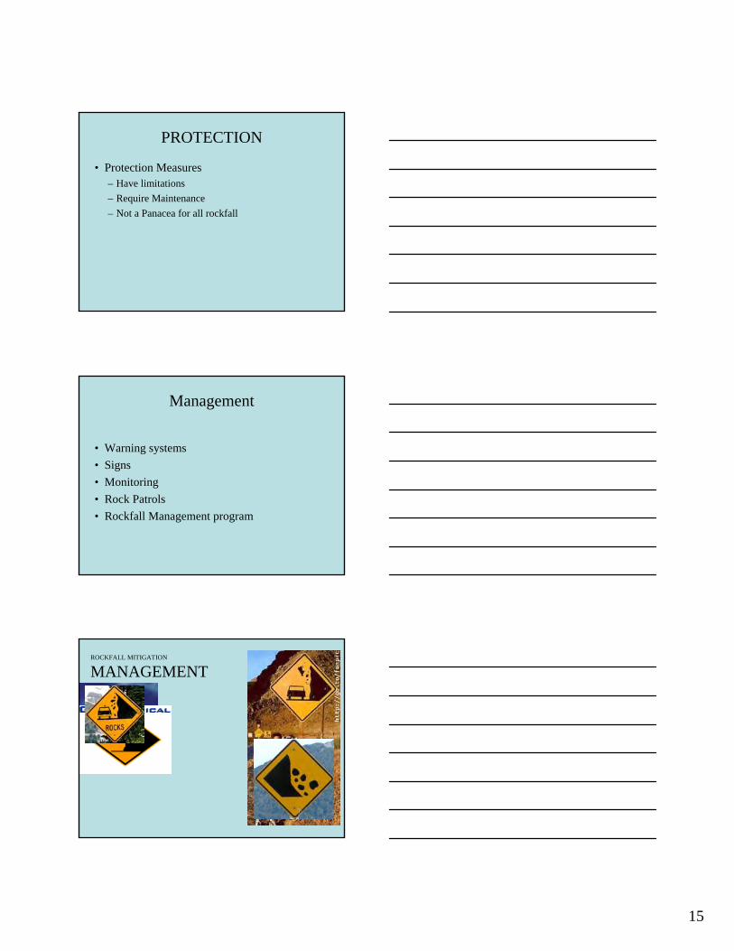
ROCKFALL MITIGATION
MANAGEMENT
15

Mitigation Selection
Summary of Non-engineered Mitigation Measures
• Warning Signs – Purpose: Alert users to the potential for rockfall and for fallen rocks to be encountered on
the roadway. – Limitations: Users become accustomed to presence of signs and ignore warnings.
• Road Patrols – Purpose: Roadway inspections during periods of higher rockfall activity to find and
remove fallen rocks. – Limitations: May encompass too many miles of road to manage in a timely manner.
• Ditch Cleaning – Purpose: Removal of accumulated rockfall debris from ditches to maintain their
effectiveness in capturing rocks. – Limitations: Temporary measure requiring repeated action by maintenance crews and a
suitable disposal site. • Monitoring
– Purpose: Use of instruments to detect incipient rockfalls. – Limitations: Lead time to events can be short.
16

SUMMARY
• Questions? • This Afternoon
– Current Events • Flexible Rockfall Fences • Wire and Cable Mesh Drapery • Anchored Wire Mesh • Analysis • Rockfall Hazard Ratings • Field Work
– Open Forum
1