rockfall table of contents - california department of
TRANSCRIPT

Caltrans Geotechnical Manual
Page 1 of 40 December 2020
Rockfall
Table of Contents
1. Introduction
2. Context Sensitive Considerations for Rock Slopes
3. Rockfall Types and Causes
4. Rockfall Hazard Rating Systems
5. Rockfall Risk Assessment and Risk Management
6. Site Investigation
7. Instrumentation and Monitoring
8. Rockfall Mechanics
9. Rockfall Analysis
10. Mitigation Selection
11. Rockfall Maintenance and Management Programs
12. Reporting
13. References
14. Rockfall Storm Damage Evaluation Form

Caltrans Geotechnical Manual
Page 2 of 40 December 2020
1. INTRODUCTION Rockfall investigations may be required for STIP projects, emergency storm damage, and normal slope maintenance operations and can involve phases K, 0, 1, 3 and M1 and M2 tasks. This module provides the process and information needed to complete a rockfall investigation. Rockfall is the movement of rock of any size from a cliff or slope that is steep enough for the rock to move down slope. Movement may involve any combination of free falling, bouncing, rolling, or sliding. Rockfall may involve more than one rock, but excludes slope failures involving large volumes of rock, such as rock avalanches or landslides (26). Rockfall has the following characteristics (38):
•
• •
•
The event involves a single block or group of blocks that become detached from the rock face. Each falling block behaves independently of other blocks. There is temporary loss of ground contact and high acceleration during the descent. The blocks attain significant kinetic energy during their descent.
Three publications frequently referenced herein are listed below. These and all other referenced documents are available via hyperlink in the References section at the end of this module.
• • •
Turner and Schuster (2012), Rockfall Characterization and Control, Brawner (1994) Rockfall Hazard Mitigation Methods McCauley et.al. (1985) Rockfall Mitigation.
Experience, especially with similar rock and slopes, should be considered in rockfall analyses and design of mitigation measures. Case histories in similar conditions should be consulted to provide additional guidance (38). The Geoprofessional should consult with their Office’s rockfall technical team representative for all rockfall work. 2. CONTEXT SENSITIVE CONSIDERATIONS FOR ROCK SLOPES Development of context sensitive solutions for rockfall mitigation is an important consideration in the planning and design process and includes all stakeholders. Mitigation design considers the safety, cost, and capacity of roadways as well as areas of scenic concerns, historical significance, and wildlife corridors (01 & 08). 3. ROCKFALL TYPES AND CAUSES The first steps in performing an investigation and developing an effective mitigation plan are to (1) identify the type of rockfall, and (2) determine the cause.

Caltrans Geotechnical Manual
Page 3 of 40 December 2020
Rockfall Type There are numerous conditions that can affect a slope and produce rockfall. A guide to the types of failures is provided in Turner and Schuster (2013) on pages 25 and 26. Rock failure mechanisms are categorized into four types (07, 26, 30, 37, 38, 42 & 43):
• • • •
Planar Wedge Toppling Circular
Rockfall Causes Rockfall occurs in areas that are subject to various types of external and internal forces. In most instances, more than one factor contributes to rockfall. These factors can be grouped into three categories: structural, environmental, and anthropogenic. Typical causes of rockfall and factors influencing rockfall behavior are listed below (07, 14, 26, 37, 38, & 43):
•
•
•
Structural o o
Adverse planar features Fractured rock
Environmental o o o o o o o o o o o o
Rain Freeze-thaw Wind Snowmelt Channeled melt/runoff Burrowing animals Differential erosion Tree roots Springs or seeps Wild animals Soil decomposition Earthquakes
Anthropogenic o o o
Poor blasting practices Vibrations from trains and construction equipment Poor slope design
In California, the greatest amount of rockfall occurs during rainstorms when supporting materials are washed away from beneath larger rocks. Loss of supporting material can also be caused by wind, snowmelt, and channeled runoff. The second most common cause of rockfall is freeze-thaw cycles where continued expansion and contraction of water in fractures destabilize blocks of rock (26).
Caltrans Geotechnical Manual
Page 4 of 40 December 2020
Other rockfall causes may exist that are not a direct result of natural processes but are rather a product of human activity. Examples are the remnant effects of poor blasting practices used in excavating rock slopes (common prior to about 1980), vibrations from trains or heavy equipment and stress relief following excavation (07, 24, 25, 26, 37, 38, & 43). Factors Influencing Rockfall Behavior Numerous factors influence the behavior of rocks after they have begun traveling from their points of origin, including:
• • • • • • • • • •
Slope height Slope angle Slope roughness Vegetation Slope geology Natural or manmade topography Rock soundness Rock size Rock angularity Rock elasticity
These factors influence trajectory, which includes travel speed, mode of travel, distance traveled, and resistance to disintegration, and have direct bearing on the design of mitigation measures (26). 4. ROCKFALL HAZARD RATING SYSTEMS Slope rating systems are typically adopted to provide a relative ranking of potentially unstable slopes. The main goal is to obtain consistent and comparable information for a series of locations to plan for safety improvements, optimize the benefits from investing limited safety budgets, and reduce maintenance and other operational costs. As a planning tool, slope rating systems facilitate a proactive approach, but they can also be used in response to a rockfall event on a single slope to both describe the event and compare it to other rockfall events in a consistent manner. To provide a uniform standard for evaluating slopes, rockfall sites must be analyzed using the procedures in the Rockfall Hazard Rating System (RHRS) (30). Characterization of rockfall and assignment of a RHRS score requires consideration of the following attributes (30, 37, 38, 42 & 43):
• Rock slope geometry • Vehicular traffic volumes • Roadway geometry • Geologic conditions • Climatic conditions • Presence of water on the slope • Rockfall history

Caltrans Geotechnical Manual
Page 5 of 40 December 2020
Other published methods, many of which are described in Turner and Schuster (2012), might be more applicable on a site-specific basis. While their use is not discouraged, they should be used in conjunction with and not in place of RHRS. 5. ROCKFALL RISK ASSESMENT AND RISK MANAGEMENT The practical application of formal risk-based approaches is difficult to achieve in real-world situations because of the investment in time and personnel. Turner and Schuster (2012) discuss a variety of approaches in use today. Use the simple risk-based approach as described in the RHRS manual. 6. SITE INVESTIGATION Characterization of site stability is determined by a field investigation, which includes a surface investigation and may include a subsurface investigation (07, 26, 37, 38, & 43). A site investigation must begin with a literature search, review of historic and current geologic maps, and aerial photo review. Refer to Geotechnical Investigations and Rock Cut Slopes for additional instruction on investigations. (For storm damage response the site investigation procedures herein may need to be abbreviated to provide quick response to the District. Use the Rockfall Storm Damage Evaluation Form at the end of this module to collect the critical site information necessary to provide first response recommendations to the client. Always bring this module with you to the field and try to collect as much of the required information presented in this Section 6. A Rockfall Technical Team member must be consulted in all storm damage situations so that proper recommendations are made given the abbreviated site investigation.) Rockfall mitigation design uses the structural characteristics and strength properties of the geomaterials. Accurate design of rockfall mitigation relies heavily on surface mapping, geomaterial identification, evaluation of erosion susceptibility, and discontinuity logging. Logging rock structure discontinuities (fracture/joint patterns) and their condition on surface outcrops is essential in the analysis for rockfall mitigation. Determination of groundwater presence, as is true of any slope, is also critical to the assessment of stability. A rockfall investigation, at a minimum, must answer these six questions:
1. Is there a rockfall problem and where is it located? 2. What is the nature and frequency of past rockfall events at these sites? 3. Where are the source area(s), travel path(s), and runout zone(s) and what are
the geological properties of each? 4. What is the likely motion of the rock traveling down the slope (rolling, bouncing,
or sliding)? 5. What size rocks typically reach the base of the slope (or point of interest) versus
their size in the source zone?

Caltrans Geotechnical Manual
Page 6 of 40 December 2020
6. How far do the rocks roll past the base of the slope (or point of interest)? Existing Slopes and New Slopes Most rockfall investigations are performed on existing slopes where rockfall has been identified. However, in some cases proposed steepened cuts to existing stable slopes may give reason to perform a rockfall assessment. This assessment should be based on several features and characteristics including RQD, fractures in core, proposed catchment areas (or lack thereof), and the presence of river deposits further up the slope that may be or become unstable. Literature Search Knowledge of the geology of the area is critical and should be obtained by examining published geologic maps and reports and aerial photographs. District Surveys typically have aerial vertical and oblique photos. Air flights can be arranged with the Highway Patrol to fly sites and take photographs. For existing cut slopes, obtain the “As-Builts” from the District Office and the file of record and/or Document Retrieval Services (DRS). See the Geotechnical Investigations. Climate Most rockfall occurrences are typically associated with heavy rainfall, rapid snow melt, freeze thaw cycles, wind, channeled runoff, and groundwater (07, 26, 38, 42 & 43). Therefore, historic precipitation and temperature data must be obtained and reviewed. Graphic representations of rockfall history versus temperature, precipitation, and wind at or near the site correlate rockfall frequency to these factors and define trends (07, 41, 42, & 43). The National Oceanic and Atmospheric Administration records and maintains weather data around the State and is available on-line. Maintenance History The history of a slope or section of road can identify trends in rock slope failure, and most importantly, the rockfall occurrence and frequency. Review maintenance and/or legal records for rockfall accident history, which provides insight into potential rockfall risk. Speak with the District’s Maintenance Engineer. Maintenance personnel can provide estimates of the rockfall size, shape, and frequency which can be used to determine the source area and the possible failure mechanism. Evidence of pavement impacts provides information on free falling distribution as well as impact energies. Caltrans Maintenance time reporting system has a category for scaling and rock/mud removal. Accessing this data can be yet another valuable resource to determine rockfall frequency and seasonal trends. Finally, direct communication with the maintenance supervisor and/or maintenance lead workers who have worked in the area may provide the best insight into the history, nature, and impact of rockfall problems at the site.

Caltrans Geotechnical Manual
Page 7 of 40 December 2020
Rockfall Characteristics There are four travel modes of a falling rock: free falling, bouncing, rolling, and sliding. In any one or combination of these modes rockfall occurs as either individual rocks or as a group of rocks. An individual falling rock, or a single rock that falls and hits other rocks, causing more rocks to fall, is considered an individual rockfall event. Such an event could also result in a group of individual rocks falling within seconds of each other, or one large group falling simultaneously. A group of rocks might also fall when an unstable rock cluster fails, resulting in a group of rocks falling together as one mass. Characterizing the rockfall event is important in developing a strategy for determining the trajectory and kinetic energy at the base of the slope. For example, individual rocks might have low mass and high velocity when compared to a larger, more massive group of falling rocks, which might have a lower velocity but a higher mass (07, 26, & 38). Size and Shape of the Rockfall The following information must be collected in and around the base of the slope, at Maintenance’s nearby rockfall disposal sites and/or below the highway:
• • • • •
Average rock size Maximum rock size Typical rock shape (tabular, spherical, disc shaped) Dimensions of the rock along three principle rock axes (x, y, and z) Specific gravity
This information will be used to estimate the weight of the rock and the moment of inertia of the falling rock body. If carefully measured, this procedure is typically within 10% of the actual weight of the rock (36). Alternatively, weigh the fallen rocks at the base of the slope directly using a load cell, available from the Foundation Testing Branch, attached to the bucket of a loader. Rockfall Source and Run Out/Impact Zone Determine the location from where rocks fall ( the source area). Determine the location where rocks first impact the ground at the base of the slope (impact zone), and where the rocks come to rest (run out zone). Knowing the beginning and final locations of the rockfall helps identify the path the rock travels. This information is important in determining the rockfall bounce height and cross-section used in the analysis. Also, from careful inspection of the rockfall path, d e t e r m i n e information on the trajectory of the rockfall by identifying impact locations on the slope and at the base of the slope, or observing where rocks have hit trees or other obstructions.

Caltrans Geotechnical Manual
Page 8 of 40 December 2020
Measure the size of rocks in the run out/impact zone and at the source t o understand about how the rocks break up during the rockfall. If large rocks are measured at the source but only fragments reach the run-out zone, the rocks are breaking up either as they fall on the slope or when they hit the road. If the former is true, then a smaller rock size would be used in the analysis, which will affect the analysis and mitigation measures (07 & 38). Field Mapping Assess the performance of the existing slopes (both cut slopes and natural slopes) to determine the limits of the unstable area. Field observations of naturally formed cuts in drainages or along the ocean and cuts outside the State Right of Way (ROW) are particularly important in providing the characteristics of a slope and rockfall (07, 26, 37 & 38). Refer to the Field Mapping section of the Rock Cut Slope module for a list of data and information to collect. The mapped area should include the active rockfall zone and any adjacent area that may influence or be influenced by the rockfall. Geologic maps on a wide variety of scales are available from the USGS, CGS, local, county and government entities, and private organizations. Collect or note the following information:
•
• •
• •
• • • • •
Slope length (measured along the slope angle and vertical height): physically measure with tape, range finder, or pace. Slope angle: physically measure with Clinometer, Brunton or Clar Compass. Slope surface: smooth, planar, undulatory, and blocky; if undulatory or blocky, note the difference in height from the ‘peaks’ to the ‘valleys’. Describe lithology of the soil and/or rock. Estimate or physically measure native slope ratios above and below cuts, as well as on nearby slopes of similar geology. Note presence of boulders, including average size, maximum size, shape, and rock type, as well as their location (top of slope, on slope (embedded or loose), at base of slope). Local stability - Note erosion features, rockfalls, slumps, rills, washes, etc. Global stability - Note presence of landslides and rockslides. Moisture features, such as seeps, springs, wet areas, and their likely causes. Assess condition of existing slopes. Describe vegetation.
Where applicable, rock structure data should be collected and recorded. In addition to basic field observations, a scan line analysis should be performed on open cut slopes or natural slopes. This information is used in estimating the Rock Mass Quality (Q) and the Geological Strength Index (GSI). A table should be developed to include the following rock discontinuity information. “Rock Slopes” (40) presents a thorough description of the following geological terms in Chapter 2, Section 2.3.

Caltrans Geotechnical Manual
Page 9 of 40 December 2020
• • • • • • • • • • • • • • •
Location Station Discontinuity orientation (Dip/Dip Direction) Type of Discontinuity (bedding, jointing, fractures, faulting, etc.) Persistence Spacing Filling Asperities Roughness Rock Quality Designation (RQD) Discontinuity Sets Discontinuity Roughness Discontinuity Alteration Discontinuity Presence of water Weakness Zones intersecting the excavation
Existing Roadway Conditions:
• • • •
•
Number of lanes Lane width Paved shoulder width and unpaved shoulder width, and slope ratio of both. Catchment Area (width of roadway between the base of the slope and the edge of traveled way available for rock and debris containment) and back slope ratio. Observations of pavement condition, presence and location of cracking, settlement, patching.
Existing man-made structures:
• • •
Walls, foundations, building types, culverts, undercrossing, utilities, etc. Note general condition of structures. Note if roadway work might impact the structure.
Field Drawings:
• • •
Develop a scaled field drawing of the area of concern Develop one or more typical cross sections of the area of concern Develop cross section with initial mitigation approach if appropriate
Photographs of the area of concern:
• •
Photos of the problem area (direct/overall) Photos of main features or any other important features inside or outside of the area
Identify additional geologic investigations that may need to be performed to adequately characterize the site, such as additional boring locations and/or geophysical studies.

Caltrans Geotechnical Manual
Page 10 of 40 December 2020
The Geoprofessional must also collect data required for the Rockfall Hazard Rating System (RHRS) (30 & 33) and the Colorado Rockfall Simulation Program (CRSP) (02 & 23). The field data necessary for RHRS and CRSP are also useful in addressing other aspects of a rockfall investigation. RHRS requires:
• • • • •
Slope height Ditch effectiveness Vehicle risk Sight distance Roadway width
• • • •
Geologic character Block size Climate Rockfall history
CRSP requires:
• • • • • • •
Slope geometry Slope inclination Slope length Surface roughness Lateral variability Slope material properties Slope coefficients
• • • • • • •
Falling rock coefficients Falling rock geometry Falling rock size Falling rock shape Falling rock material properties Falling rock durability Falling rock mass
When possible, investigate rockfall source zone instabilities with analytic tools and engineering-mechanics-based approaches (05). Several easily quantifiable rock mass properties are typically used to predict rock mass behavior. The required analysis, done largely during the field mapping, focuses on identifying likely source zones, the rock mass characteristics of these zones, and the relative potential for each zone to generate rockfall. Use this approach to identify areas that need attention and to assess the effectiveness of potential mitigation measures (38). The recommended procedures are the Rock Quality Designation (15 & 38), the Rock Mass Rating (05) and the Modified Q-Rating System (04).

Caltrans Geotechnical Manual
Page 11 of 40 December 2020
7. INSTRUMENTATION AND MONITORING Monitoring observes changes to surface exposures, or measures movements or strains within the rock mass. A typical monitoring program seeks to:
•
•
•
•
Maintain safe operation of the transportation facility and to protect the traveling public; Provide advance notice of any instability, thus allowing for the early introduction of appropriate mitigation strategies; Provide for the protection of personnel and equipment during construction operations in the vicinity of, and for the modification of, any excavation activities to minimize the impact of the instability; Provide geotechnical information in order to analyze slope failure mechanisms, design appropriate remedial measures, or conduct a re-design of the slope.
Rockfall monitoring work is performed by the Geoprofessional with the assistance of District personnel. Another option is a service contract, working through Maintenance or Construction to obtain monitoring services. Monitoring Slope Movement The techniques available to measure rock deformation belong to two general categories:
•
•
Surface measurements: techniques range from simple visual observations, rock patrols and photographic recording to more sophisticated approaches that include optical and electronic surveying, use of differential Global Positioning System (GPS), terrestrial photogrammetric approaches, and the newest technologies—laser scanning (LiDAR) and radar scanning using differential interferometry. Ground displacement measurements: techniques include the application of manual, mechanical and electronic instruments, such as extensometers, strain gauges, and crack gauges or simply measure the distance between two points with a tape measure (07 & 38).
Monitoring Rockfall Characteristics Rockfall factors to monitor are (1) Location, (2) Frequency, (3) Quantity, (4) Size, (5) Time of the year, and (6) Weather. Monitoring is typically accomplished utilizing Maintenance forces and their routine patrolling of the roadways. Over the years various forms have been developed for Maintenance personnel to record rockfall activity at a site or sites. Sample forms are available from the Rockfall Technical Team. The most successful forms have been the simplest. This information is invaluable and continued collection and record keeping should be encouraged.

Page 12 of 40 December 2020
Caltrans Geotechnical Manual
8. ROCKFALL MECHANICS
Kinetic Energy Kinetic energy is the most common parameter for describing rockfall in engineering design. Rockfall motion is the sum of translational and rotational kinetic energy and is expressed mathematically as:
Where 𝑚𝑚 is the mass of the rock, 𝑣𝑣 is the translational velocity, I is the moment of inertia and ω is angular velocity.
Potential Energy The potential energy of a rock is:
Where m equals mass, 𝑚𝑚 equals the acceleration of gravity and ℎ equal height above the impact zone.
When a rock experiences free fall, its initial potential energy is progressively converted into kinetic energy. The maximum potential vertical velocity of a rock free-falling from a source is:
Where 𝑣𝑣 equals velocity just before impact, 𝑚𝑚 equals gravitational acceleration and ℎ is the maximum vertical height of the fall.
Refer to Turner and Schuster (2012) for a complete discussion on rockfall mechanics.

Caltrans Geotechnical Manual
Page 13 of 40 December 2020
9. ROCKFALL ANALYSIS Rockfall analysis helps obtain an understanding of the rockfall behavior, which is used to assess potential mitigation measures. Every slope is unique and has variable slope angle, rock type, slope height, topography, soil cover, and vegetation. These features must be characterized because they affect rockfall energy and trajectory. The various methods used to analyze rockfall energies and trajectories include the quantification of rockfall velocity, impact energy, and bounce heights. The three principle approaches to analysis shown here are discussed in Turner and Schuster, 2013 (38).
• Mathematical Analysis (Table 1) o o
Rock mass stability analysis Rockfall trajectory analysis
Rockfall simulation analysis (computer analysis) Empirical analysis Field testing
All these approaches are based on, to differing degrees, actual field rock rolling data, and are used as tools to assist in the design and the assessment of mitigation measures (07 & 38). Where possible, all three methods should be used to analyze the rockfall trajectories at the site. Use of the large body of empirical rockfall data is strongly encouraged. Rock Mass Stability Analysis The analysis of a source of rockfall or the stability of an entire rock slope has two goals: (a) identification of kinematically unstable blocks and (b) investigation of the factors influencing the stability of such blocks. Stereographic, kinematic, and limit equilibrium analytic methods are discussed in Rock Cut Slopes and summarized in Table 1.

Caltrans Geotechnical Manual
Page 14 of 40 December 2020
Table 1: Conventional Methods of Mathematical Rock Slope Analysis (38)
Analysis Method
Critical Input Parameters Advantages Limitations
Stereographic and Kinematic
Critical slope and discontinuity geometry;
representative shear strength
characteristics.
Simple to use and show failure potential. Some methods allow
analysis of critical key-blocks. Can be used
with statistical techniques to indicate probability of failure
and associated volumes.
Suitable for preliminary design or for non-critical slopes, using mainly joint orientations. Identification of critical joints requires engineering judgment.
Must be used with representative
joint/discontinuity strength data.
Limit Equilibrium
Representative geometry,
material/joint shear strength, material
unit weights, groundwater and
external loading/support
conditions.
Much software available for different failure modes (planar,
circular, wedge, toppling, etc.). Mostly
deterministic but some probabilistic analyses in 2-D and 3-D with multiple materials, reinforcement and
groundwater profiles. Suitable for sensitivity analysis of Factor-of-Safety to most inputs.
Factor-of-Safety calculations must assume instability mechanisms and
associated determinacy requirements. In situ
stress, strains, and intact material failure not considered. Simple
probabilistic analyses may not allow for sample/data
covariance.
Rockfall Simulation
Representative slope geometry and surface condition. Rock block sizes,
shapes, unit weights, and coefficients of
restitution.
Practical tool for siting structures and catch fences. Can utilize
probabilistic analysis. 2-D and 3-D codes
available.
Limited experience in use relative to empirical design
charts.
(From “Rockfall: Characterization and Control ©”, National Academy of Sciences. Materials used with permission of the Transportation Research Board.") Rockfall Trajectory Analyses When possible, use the following three methods to analyze rockfall trajectories. The first is to rely on empirical data that characterize the behavior of rockfall for different slope characteristics. The second is to perform field tests where rocks are rolled and the behavior of the falling rocks is observed. The third is to construct a rockfall simulation using the analytical models developed for that purpose.

Caltrans Geotechnical Manual
Page 15 of 40 December 2020
Empirical Analysis Using data from field testing, researchers developed tables and charts to describe rockfall behavior given slope parameters such as slope angle and height. For rockfall impact and runout analysis use the following three methods. a. Rockfall Shadow Zone
For planning studies, use the Rockfall Shadow Zone (22) to determine the maximum distance rocks can travel from the base of the slope. A minimum shadow angle of 27.5° should be used for the preliminary estimation of the maximum rockfall runout zone (22).
Figure 1: Schematic diagram of the characteristic rockfall path profile. A-C is the talus slope with mean angle β1 and C-D is the rockfall shadow with a shadow angle β2, β3 is the substrate angle (22).
Caltrans Geotechnical Manual
Page 16 of 40 December 2020
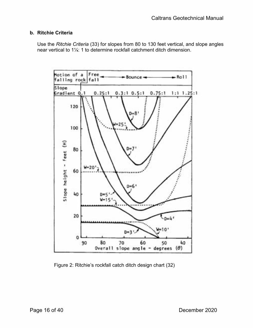
b. Ritchie Criteria Use the Ritchie Criteria (33) for slopes from 80 to 130 feet vertical, and slope angles near vertical to 1¼: 1 to determine rockfall catchment ditch dimension.
Figure 2: Ritchie’s rockfall catch ditch design chart (32)

Caltrans Geotechnical Manual
Page 17 of 40 December 2020
c. Rockfall Catchment Area Design Guidelines Use the Rockfall Catchment Area Design Guidelines (30 & 32) for slopes less than or equal to 80 feet vertical and slope angles from vertical to 1V:1H to determine rockfall impact and run out zones. From these charts, a designer selects the most appropriate ditch dimension and inclination required to provide adequate catchment.
Figure 3: Definition of impact location and roll out distance (22).
Although there is no widely accepted standard for the retention rate, many current designs achieve at least an 85% to 90% retention rate (38). On the other hand, project limitations such as right of way or excavation quantities may prevent designs with such high retention rates. The Department may have to accept an improvement in retention in lieu of ideal retention.

Caltrans Geotechnical Manual
Page 18 of 40 December 2020
Field Testing An attempt should be made to roll, film, and analyze actual rockfall as part of the analysis and mitigation design. The preferred method is to perform rock rolling tests at the site, as this will provide the most accurate information for rockfall analysis. However, this is not always possible due to safety, economic, and environmental limitations. Field testing works best if the test area can be prepared without impacting the travelled way. An alternative is to conduct the rock-rolling tests on a similar slope of similar rock type and characteristics away from the road or on a road with less traffic (07 & 38). The rocks being rolled from the source zone (i.e. scaled) or similarly sized rocks on the top of the slope can be used. When planning a test, there are three principle requirements to consider:
• • •
Accessible test rocks Visible and accessible test slope Data collection equipment and placement
Caltrans developed a Rockfall Barrier Testing Guideline in 1999 (16) and it should be used to develop the testing program. Caltrans has also developed a new technique to film and measure rolling rocks (34). Caltrans Office of Audiovisual Communications will provide video support for rock rolling tests. Turner and Schuster (2012) and Brawner (1994) present thorough discussions on performing field tests. Included in these references are some useful rock rolling data collection forms. Rockfall Simulation Computer modeling is used as a tool to study the behavior of rockfall, determine the need for mitigation, and aid in the design (07). Modeling should be used in conjunction with field data and good judgment. Computer modeling allows designers and investigators to observe dozens or even hundreds of simulated rockfall events. Mathematical modeling analysis must be performed using the Colorado Rockfall Simulation Program (CRSP) (02 & 23). Other published models, many of which are described in Turner and Schuster (2012), may prove to be applicable on a site-specific basis. While their use is not discouraged they should only be used in conjunction with CRSP. Rockfall simulation relies on field observations and assumptions on the starting and ending points of a rockfall, rock size, and actual slope data (listed in 6.8, “Field Mapping”). The model is run and various input coefficients are calibrated until the model reflects actual field observations. Another approach to determining the values for input coefficients is to perform field rock rolling tests and then model the observed rockfall trajectories to calibrate the various input coefficients. In either case, the calibrated model is then used as a predictive tool for modeling different slope configurations and rockfall sizes.

Caltrans Geotechnical Manual
Page 19 of 40 December 2020
10. MITIGATION SELECTION The Geoprofessional must consider four potential mitigation strategies. Each strategy is weighed against the purpose of the project and potential costs. The strategies are presented below in order of cost and effectiveness (Tables 2 to 6):
1. Avoidance measures rely on relocation, or realignment of a road away from the rockfall source. Avoidance is always the best solution but is typically by far the most expensive.
2. Stabilization measures include changes to the slope, or engineered features, to reduce the likelihood of occurrence of a rockfall. Stabilization generally has more moderate costs, but, requires maintenance and has associated risk.
3. Protection techniques are used to control rockfall once the rocks destabilize. Protection is less expensive, but has higher maintenance costs and increased risks.
4. Management includes warning signs, monitoring, and rock patrols. Management has low costs, but the risk may be appreciably greater.
Each strategy must be considered for each project and in many cases combinations of strategies are used as the final solution. Consideration should be given to the level of improvement for each strategy. For example, 100 percent mitigation may not be feasible, but improvement of 50 percent may significantly increase safety. All viable strategies should be presented to the client to help in the decision-making process. Mitigation measures are commonly evaluated based on (38):
• • • • • • • •
Complexity Effectiveness Durability Constructability Environmental Aesthetics (context-sensitive solutions) Cost Ongoing maintenance requirements
The Rockfall Technical Team maintains an ongoing inventory table for each District’s rockfall mitigation measures (12). The inventory is organized by location and year constructed and should be used, along with your Rockfall Technical Team representative, to find similar projects. Stabilization, protection, and avoidance measures make up most rockfall mitigation work. Table 2 provides a qualitative comparison of each of the mitigation measures. The comparisons are based on routinely considered criteria including complexity, effectiveness, durability, constructability, traffic impacts, environmental and aesthetic effects, cost, and maintenance requirements.

Caltrans Geotechnical Manual
Page 20 of 40 December 2020
Table 2: Qualitative Comparison of Mitigation Measures (38).
MITIGATION MEASURE
SELECTION CRITERIA
Com
plex
ity
Effe
ctiv
enes
s
Dur
abilit
y
Con
stru
ctab
ility/
Spe
cial
Ex
perti
se
Roa
d C
losu
re/
Traf
fic
Res
trict
ions
Envi
ronm
enta
l Li
mita
tions
Aest
hetic
Im
pact
s
Cos
t
Mai
nten
ance
R
equi
rem
ents
AVOIDANCE Tunnels VH VH H H P L-M L-H VH M-HRealignment M-VH M-VH H M P M-H L-H H-VH M-HElevated Structures M-VH M-H L-H M P L-H L-M VH M-HSTABILIZATION Removal: Scaling L-M L-H L-M M Y L L L-M L-MBlast Scaling M-H L-H M M-H Y L-M L L L-MTrim Blasting M-H M-H M-H M-H Y L-H L-H M L-MRe-sloping L-H M-H H L-M Y L-H L-H M-H L Reinforcement: Dowels M M-H H H P L L M-H L Shear Pins M M M H P M M M L Rock Bolts M-H M-H H H P L L M-H L Shotcrete M-H M-H M-H H P M-H H M-H L Buttresses M-H H H M P L-H H M-H L Cable Lashing M-H L-M L-M M P L-H M M L-MWhalers/Lagging M M L-M M P L-H M-H M L Drainage: Weep Drains L L-H M L P L-H L L H PROTECTION Mesh /Cable Nets: Slope Protection L-M M-H M-H M Y M-H M-H L L-MAnchored Mesh M M M M P M H L-H M-HSuspended Systems L-M M-H M-H M Y M-H M-H L-M L-M
Catchment Areas/Sheds: Ditches/Berms L M-H H L P L-M L-M L-H H Rockfall Sheds VH H M-H H P H H H L-MBarriers: Rigid Barriers L M-H L-M L P L L L M-HFlexible Barriers M M-H M-H M P L L M M-HMANAGEMENT Warning Signs L L-M na na N L-M L L L-MRoad Patrols L L-M na na N na na L-H H Scaling L-M L-H L-M M Y L L L-M L-MDitch Cleaning L L-H na na Y L-M na L-M H Monitoring M-H L L-H M-H N L L L-H L-H
L = low, M = medium, H = high, VH = very high, N = no, Y = yes, P = possibly, na = not applicable (From “Rockfall: Characterization and Control ©”, National Academy of Sciences. Materials used with permission of the Transportation Research Board.")
Complexity Effectiveness DurabilityConstructability / Special Expertise Road Closure/ Traffic Restrictions
Environmental Limitations Aesthetic Impacts Cost Maintenance Requirements

Caltrans Geotechnical Manual
Page 21 of 40 December 2020
Avoidance Avoidance entails moving an existing or planned facility away from a rockfall zone. The available alternatives require a shift in either horizontal or vertical position. Realignment of a highway away from the base of an unstable slope or tunneling through the slope requires a horizontal shift of the facility. Viaducts, stacked lanes, and separated grades using various retaining wall options rely on a vertical shift, which elevate facilities to avoid or reduce exposure to rockfall (38). Avoidance measures, while costly, are a viable solution for Caltrans. Many examples exist throughout the state most notably, the Confusion Hill realignment (01-Men-101-PM 99), Emerald Bay Viaduct (03- ), Devils Slide Tunnel (04-SM-001-PM 38.5/40) and Pitkin’s Curve Bridge (05-Mon-001-PM 21). Many smaller avoidance projects have been completed in the State, the majority of which utilize viaducts to move the roadway away from the slope and allow rocks to pass under the roadway. Table 3 presents a description, purpose, and limitations of avoidance measures.
Table 3: Avoidance Measures (38)
AVOIDANCE MEASURE DESCRIPTION/PURPOSE LIMITATIONS
Tunnels Avoid unstable slopes by moving the roadway inside the rock mass away from external rockfall sources.
Problems associated with traffic in confined space. Long tunnels require lighting and special ventilation. Expensive.
Realignment Full road realignment or facility relocation to move away from rockfall area.
Often the old road must be maintained for existing access. Commonly there is limited space for this option. Expensive.
Elevated Structures
Used to span the anticipated rockfall paths allowing rockfalls to pass beneath.
The structure must completely span the active area to avoid being damaged by rockfalls. Expensive.
Stabilization The goal of stabilization is to reduce the potential for rockfall by preventing or inhibiting material from dislodging at the source area through either a reduction in the driving forces, an increase in the resisting forces, or both (02, 19, 26, 27, 35, 38, 39, 40, 42 & 43). Table 4 presents a description, purpose and limitations of each stabilization measure.

Caltrans Geotechnical Manual
Page 22 of 40 December 2020
Table 4: Stabilization Measures (38)
STABILIZATION MEASURE DESCRIPTION/PURPOSE LIMITATIONS SPECIFICATION
Removal: Scaling Removal of loose rock from slope by
means of hand tools and/or mechanical equipment. Commonly used in conjunction with most other design elements.
A temporary measure that usually needs to be repeated every 2 to 10 years as the slope face continues to degrade.
NSSP available from your RTT representative.
Rock Removal/ Blast Scaling
Removal of loose rock or large rock blocks from slope by means of blasting or chemical expanders.
Damage from fly rock and rockfall, and possible undermining or loss of support by key-block removal.
Rock Excavation (SSP 19-4-X1) Controlled Blasting (SSP 19-4-X2)
Trim Blasting Used to remove overhanging faces or protruding knobs that may act as launch features on a slope.
Difficulties with drilling, debris containment, and safety.
Rock Excavation (SSP 19-4-X1) Controlled Blasting (SSP 19-4-X2)
Re-sloping Cutting the rock slope at a flatter angle to improve slope stability and rockfall trajectories.
May have right-of-way or environmental issues.
Earthwork
Reinforcement: Dowels Untensioned steel bars/bolts installed to
increase shear resistance and reinforce a block. Increases normal-force friction once block movement occurs.
Passive support requires block movement to develop bolt tension. Slope-access difficulties.
NSSP available from your RTT representative.
Shear Pins Provides shear support at the leading edge of a dipping rock block or slab using grouted steel bars.
Cast-in-place concrete needed around bars to contact leading edge of block. Access difficulties.
NSSP available from your RTT representative.
Rock Bolts Tensioned steel bars/bolts used to increase the normal-force friction and shear resistance along potential rock-block failure surfaces. Applied in a pattern or in a specific block.
Less suitable on slopes comprised of small blocks. Difficult to access slope.
NSSP available from your RTT representative.
Shotcrete Pneumatically applied concrete requiring high velocity and proper application to consolidate. Primarily used to halt the on-going loss of support caused by erosion and spalling. Also helps retain small supporting rock blocks.
Reduces slope drainage. Can be unsightly unless sculpted or tinted. Wire mesh or fiber reinforcement required. Needs a minimum 2-inch (5-cm) thickness to resist freeze/thaw. Quality and durability are very dependent on nozzleman skills.
Buttresses Provide support to overhanging rock or lateral support to rock face using either earth materials, cast concrete, or reinforcing steel.
Height limitations. May form a roadside hazard and be unsightly.
Cable Lashing Anchored, tensioned cable(s) used to strap a rock block in place. May be used in conjunction with cable nets or wire mesh. Also used as a temporary support during rock-bolt/dowel drilling activities.
Due to slope and/or block geometry, typically movement must occur for full cable resistance to develop.
NSSP available from your RTT representative.
Drainage: Weep Drains Reduces water pressures within a slope
using horizontal drains or adits. Commonly used in conjunction with other design elements.
Difficult to quantify the need and verify the improvements achieved.
(From “Rockfall: Characterization and Control ©”, National Academy of Sciences. Materials used with permission of the Transportation Research Board.").

Caltrans Geotechnical Manual
Page 23 of 40 December 2020
a. Scaling
Scaling is considered both a stabilization and management measure. In some instances scaling removes the unstable section and requires no additional work. However, in most instances slope scaling needs to be performed periodically. There are many variables that dictate how often a slope needs to be scaled. If a slope requires frequent scaling, every 1 to 2 years or less, then other measures should be considered to mitigate rockfall at the site. Caltrans has a hand scaling program, which includes experienced scaling crews, a code of safe operating practices, in-house training, slope assessment procedures, and scaling operation guidelines (10, 11 &13). Caltrans crews are typically utilized to perform hand scaling in emergencies and as inspectors during contract scaling operations. Several Districts have management programs and annually hand scale slopes as a preventative measure. When hand scaling operations are considered, a Slope Scaling Assessment Form must be completed as part of the investigation and prior to any scaling operations (11). Mechanical scaling may be recommended when slope stability is unpredictable. In this situation the “no scaling” alternative must be considered. A common method is to drag a heavy object across the slope face with a crane or cable system. This technique removes loose rock without anyone needing to be on the slope. It is both difficult to estimate the volumes that will be generated and to evaluate the condition of the final slope face. Many references recommend hand scaling be done following mechanical scaling (7, 26, and 38). Therefore, upon completion of mechanical scaling operations the geoprofessional should evaluate the need to perform hand scaling or other mitigation methods.
b. Blasting
Controlled blasting may be used to selectively remove individual rocks or rock clusters that cannot be removed by hand scaling (9). The recommended procedure is to place light charges in strategically drilled holes. Alternatives to explosives are the Boulder Buster™, chemical expanders and hydraulic splitters (9). Blasting under cable mesh drapery is the recommended method to blast on a slope face when there are strict requirements to control fly rock and debris. Caltrans has a blasting program for breaking rocks and trim blasting. The program is supported by an in-house training program, which includes a blasters manual (9). The blasters manual is an excellent resource and reference for contract blasting operations.

Caltrans Geotechnical Manual
Page 24 of 40 December 2020
c. Resloping Resloping redesigns the cut slope to increase stability, improve roadway geometrics, and increase rockfall catchment. The Rock Cut Slope Design module must be used when resloping rock cuts.
d. Reinforcement Rock bolts, dowels, and shear pins are effective methods for slope stabilization. Use of these designs requires a complete understanding of the rock structure of the slope. Measuring and evaluating the rock structure is thoroughly discussed in Rock Cut Slopes.
e. Shotcrete When using shotcrete, provide adequate drainage behind the shotcrete by using weep holes. Plain shotcrete is considered unsightly, but today it is common practice to color and sculpt the shotcrete to blend in to the natural background.
f. Buttresses Two common buttressing approaches are covering the slope or providing support to a rock or overhang. Slopes can be covered with rock slope protection (RSP) to prevent erosion of the slope face. There are some limitations on slope height and slope angle but it is a very effective measure. Another method of covering a slope is to build retaining structures, single or multi-tiered, with backfill up to the top of the slope. More conventional buttresses provide underlying support via structural members to overhanging rocks and outcrops.
g. Cable Lashing In many instances a large rock or group of rocks on a slope face are key blocks supporting material above. Removal of these blocks could destabilize a larger mass. In these cases, it is often best to stabilize the rock or rocks in place. While this can be done with rock dowels and shear pins, cable lashing can be done with minimal worker exposure on the slope. Anchors are constructed up-slope, from which cables, used as straps, are wrapped across the rocks and secured to the anchors. Covering the rock face with cable nets and attaching the cable straps to the nets is a technique often used to cover more surface area. An example of calculating the force to prevent overturning of a rock block is shown and is used to determine the number of cables straps and anchor capacity.

Caltrans Geotechnical Manual
Page 25 of 40 December 2020
Figure 4: Method to determine required restraining force and anchor capacity. ∑MA=> Wy = Tx, T=Wy/x.

Caltrans Geotechnical Manual
Page 26 of 40 December 2020
Protection Protection measures stop, control, or deflect falling rock. Conditions that typically warrant protection measures include (38):
• •
•
Rockfall source areas lie beyond Caltrans right of way. The extent or nature of the source area is impractical or excessively costly to stabilize. Stabilization is deemed infeasible. Avoiding the unstable slope by facility relocation is not practical or is excessively costly. Avoidance is deemed infeasible.
Table 5 presents a description, purpose, and limitation of protection measures.
Table 5: Protection Measures (38)
PROTECTION MEASURE DESCRIPTION/PURPOSE LIMITATIONS SPECIFICATION
Mesh/Cable Nets: Draped Mesh Slope Protection
Hexagonal wire mesh, cable nets, or high-tensile-strength steel mesh placed on a slope face to slow erosion, control the descent of falling rocks, and restrict them to the catchment area.
Requires a debris collection ditch area. Must consider debris and snow loads on anchors. Typically limited to 4-ft-minus (1.2-m) rocks.
NSSP available from your RTT representative.
Anchored wire mesh/cable nets/ high tensile strength steel mesh
A free draining, pinned/anchored-in-place net or mesh. Used to retain rocks on a slope.
May form pockets of loose rock as rockfall debris accumulates. Can be difficult to clean out.
NSSP available from your RTT representative.
Suspended Systems (Attenuators)
Wire or cable mesh draped by fence posts or suspended across chutes. The fence (impact zone) intercepts and attenuates falling rocks initiating upslope, and directs them beneath the mesh and into the roadside catchment area.
Require debris-collection ditch areas. Must consider debris and snow loads on anchors. Typically limited to 4-ft-minus (1.2-m) rocks.
NSSP available from your RTT representative.
Catchment Areas/Sheds: Ditches/Berms A shaped catchment area at the base of a
slope used to contain rockfall. Tall slopes require wide fallout areas. May have right-of-way or environmental issues.
Rockfall Sheds A covered structure used to intercept and divert rockfalls.
Expensive, hazards associated with traffic in confined space. Must consider downslope issues.
Barriers: Rigid Barriers (with or without fence extension)
Rigid barrier walls used to intercept falling rock and restrict them to a prescribed fallout area. Examples include Jersey barriers, guardrails, and other concrete, gabion, or mechanically stabilized earth (MSE) walls.
Rigid systems are more prone to damage by higher-energy events. Complicates debris cleanout and snow plowing.
Flexible Barriers Wire ring, high-strength wire mesh or cable-net panels with high-energy absorption capacity supported by steel posts and anchor ropes with braking elements. Typically proprietary systems.
Require room for barriers to deflect during impacts. Must be cleaned out periodically. Complicates snow plowing.
NSSP available from your RTT representative.
(From “Rockfall: Characterization and Control ©”, National Academy of Sciences. Materials used with permission of the Transportation Research Board.")

Caltrans Geotechnical Manual
Page 27 of 40 December 2020
a. Flexible Rockfall Fences
Caltrans has over 100 flexible rockfall fences throughout the state (12). Flexible rockfall fences are suitable for energies under 1000 kJ (38). Above 1000 kJ, the fences typically require maintenance after a single design load impact. When rockfall impact energies are above 1000 kJ, careful consideration should be given to the suitability of using a fence. Consider other protection measures (earthen berms, timber walls, attenuators, etc.) or avoidance or stabilization measures. In general, fences for high impact energies should be used where the higher impact energies are infrequent. Standard fence testing guidelines test at two energy levels; service energy level (SEL) and maximum energy level (MEL). SEL represents the energy capacity (rating) of system from two impacts and the fence does not require maintenance. MEL represents the maximum energy capacity (rating) of a fence from a single impact, regardless of the condition of the fence as long as the rock is stopped. Standard testing procedures require the MEL to be 3 times the SEL. When choosing a fence, consideration should be given to frequency of SEL and MEL rockfall impacts as this will directly correspond to maintenance requirements and construction costs. For most typical highway rock cuts, designing for SEL is appropriate. Caltrans flexible rockfall fence specifications specify post spacing, post dimension, mesh type, and deflection limits. The specification does not require that a fence be tested by a specific test. Instead, proof of performance is required which can be a combination of testing, calculations, and case histories. Use the Rockfall Catchment Area Design Guide (32) and the potential energy formula to design flexible rockfall fences. This manual is applicable for slopes less than or equal to 80 feet vertical, between 45 and 90 degrees, and rockfall dimensions less than 3 feet. For example, consider a site with a vertical slope height of 60 feet, a slope ratio of ½:1, a 6-foot dirt shoulder, an 8-foot paved shoulder, and a rockfall size of 2 feet in dimension.
The potential energy is:
PE=mgh= weight x height (imperial units)
w = (2’x2’x2’) (165pcf) = 1320 pounds
PE=1320 pounds x 60 feet
PE=39.6 foot- tons (106.9 kJ)

Caltrans Geotechnical Manual
Page 28 of 40 December 2020
Determine fence height by using the Rockfall Catchment Area Design Guide by simple geometry. For example, as determined from catchment charts in the Rockfall Catchment Area Design Guide for 99% containment, the catchment width needs to be 11 feet. Therefore, the design fence, to have 11 horizontal feet between the top of the fence and the slope face, is 10 feet. In this example the fence should be a 110-kJ energy system, 10 feet in height.
Figure 5: Using the Rockfall Catchment Area Design Guide to determine required fence height as a function of containment.
b. Cable and Wire Mesh Drapery
Covering a slope with wire or cable mesh drapery is widely used throughout theState (12). Drapery systems must be designed in accordance with DesignGuidelines for Wire Mesh/Cable Net Slope Protection (29). Of note are theappendices where ground anchor spacing and ground anchor load requirements aredetermined based on slope height, slope angle, and mesh type. Interface frictionbetween the mesh and the ground surface must be used when designing anchorloads and spacing. Snow loading, ground anchor design, and anchor testing are alsowell documented. Draped meshes need some catchment at the base of the slope tocontain material as it migrates downward and accumulates at the base of the slope.Where there is little or no catchment, anchored mesh should be considered (Section10.3.3).
Mesh selection criteria is based on rock size. Use double twisted wire mesh (38) forslopes with rockfall sizes less than 2 feet maximum dimension. For rockfall larger

Caltrans Geotechnical Manual
Page 29 of 40 December 2020
than 2 feet, but less than 5 feet, use cable mesh (38). Larger rockfall sizes require a special drapery design and may warrant an alternative strategy. In some cases, the top of the drapery needs to be elevated to intercept rockfalls sourced upslope of the installation, where natural topography channels rockfall, or along abrupt slope convextities. For example, consider a slope that is 100 feet high (vertical) with a 1:1 slope ratio and maximum rockfall sizes of 18 to 20 inches. Because the rock size is less than 2 feet, double twisted wire mesh is selected. Anchor load and spacing for the project is determined from Appendix A, Figure A-1 in the Design Guidelines for Wire Mesh/Cable Net Slope Protection (29). Anchor spacing, often dependent on topography, supports 40 foot spacing. For a 40-foot anchor spacing and a 100-foot high slope the individual anchor load will be 600 pounds.
Figure 6: Graph plots anchor load vs. spacing for double-twisted wire mesh for a planar,
45° slope ranging in height from 50 to 300 ft (29). c. Anchored Cable and Wire Mesh
Anchored meshes for rockfall are different from anchored meshes used for slope stabilization. Use anchored mesh designs when there is little to no catchment at grade. In this case the standard drapery design is employed with the mesh anchored to the slope so the rocks cannot migrate down slope. At present there are over 25 anchored mesh installations in the State (12). Anchored meshes do not increase stability by imparting an active force on the slope face, but instead are passive systems that stop rocks from falling to the base of the slope by containing them behind the mesh (06). Caltrans uses double twisted wire mesh and cable mesh in its
Caltrans Geotechnical Manual
Page 30 of 40 December 2020
anchored systems. The Geoprofessional should use the punching shear strength of the mesh in the determination of the anchor loads. The design load of the dowels need not exceed the material punching shear.
d. Cable and Wire Mesh Attenuators Suspended wire and cable mesh barriers are a hybrid of drapery systems and flexible rockfall fences. Also referred to as attenuators, these systems catch rolling and bouncing rocks, attenuate the energy, suppress the trajectory, and guide the rock to the base of the slope into a catchment area. However, in many instances in practice and in testing, the velocity of the rock at the base of the slope is such that the rock can exit into the roadway, sometimes requiring a secondary barrier at grade. Colorado DOT did an extensive study of attenuator systems from which a standard design was developed for energies up to 500 kJ (03). Other studies also support the capabilities of these systems (38). To date all attenuator testing has been performed for energies less than 500 kJ. Caltrans currently has over 15 attenuator systems throughout the state, all of which are performing per design (12, 18). Attenuator development is rapidly progressing as these systems combine the best maintenance attributes from draperies and fence systems, making these systems very popular with maintenance personnel.
e. Catchment Ditches Properly dimensioned catchment ditches and berms are the most effective and maintainable rockfall mitigation measures available. The orientation of the foreslope has a dramatic influence on rollout distances. Rollout distance drops dramatically as the foreslope angle increases. A vertical foreslope section effectively stops rolling rocks; however, it poses safety hazards to passing vehicles and is not applicable to many roadway geometrys. Catchment design requires space, and as corridor width becomes more restricted, maximizing ditch and berm design for 100 percent containment is rarely achievable. However, increasing catchment effectiveness is still a viable and appropriate alternative. For example, consider a site where there is an existing 6 feet of catchment and, due to limited corridor widths, only 6 additional feet of catchment are available. Standard design criteria require 15 feet for 99% containment. Although the proposed catchment is only 80% of the required width for 99% containment, the catchment width has been doubled and both the impact and runout containment have been improved. This can be quantified by calculating RHRS scores for both the existing and proposed catchment widths. This approach can be used by the design team to balance all of the factors involved in the project and document the improvement in safety achieved by the design. Design of catchment ditches less than 80 feet vertical must be in accordance with the pooled fund study report Rockfall Catchment Area Design Guide (32). For slopes above 80 feet vertical the Ritchie Criteria must be used for design and supplemented with CRSP (38).

Caltrans Geotechnical Manual
Page 31 of 40 December 2020
f. Rock Sheds Rockfall sheds are not often used in California but, due to corridor restrictions and increasing material disposal difficulties, are becoming more viable. Currently there is one rock shed at Rain Rocks (05-MON-1-PM 21) on the Big Sur coast. Another shed is currently being designed at the Ferguson Rockslide (10-MPA-140-PM 42).
g. Rigid Barriers Rigid barriers, which include timber and concrete lagging walls, earthen berms, Jersey barrier, k-trail, and gabion basket barriers, are being used more infrequently in favor of flexible barriers. Rigid barriers are primarily used where rockfall and mudflows occur at the same location, and there is zero tolerance for the mud passing through. District 7 maintains many rigid barrier systems along the Malibu Coast and has developed a set of plans for timber and concrete barriers which are available through the Department Rockfall Technical Team. Mechanically Stabilized Earth Walls (MSE) and Reinforced Soil Slopes (RSS) barriers, although categorized as rigid, deform to absorb energy and are becoming more popular worldwide, especially with the increasing demand for higher energy capabilities. Considerable testing and research has been done to develop barriers with steep slopes that have minimal width requirements and high-energy capacity (38).

Caltrans Geotechnical Manual
Page 32 of 40 December 2020
Management Long-term mitigation of rockfall at a single location or along an entire transportation corridor may not be achievable within a reasonable time frame for financial, environmental, or other reasons. In such cases, a variety of maintenance and/or monitoring activities may provide a significant reduction of the risk and improve public safety by reducing the exposure of road users to unstable slopes during critical periods of slope instability. Risk-reduction measures include cautionary signs, observational or instrumentation monitoring, warning systems, regular maintenance patrols, and preemptive closure of the facility. Interim stabilization or protection measures are also valuable tools for reducing rockfall at a specific location or for a short duration. These risk-reduction measures principally improve safety by increasing traveler awareness or by reducing exposure during critical periods of slope instability (38).
Table 6: Management Measures (38) MANAGEMENT
MEASURE DESCRIPTION/PURPOSE LIMITATIONS
Warning Signs Alert users to the potential for rockfall and for fallen rocks to be encountered on the roadway.
Users become accustomed to presence of signs and ignore warnings.
Road Patrols Roadway inspections during periods of higher rockfall activity to find and remove fallen rocks.
May encompass too many miles of road to manage in a timely manner.
Scaling (see protection measures)
Removal of loose rock from slope by means of hand tools and/or mechanical equipment. Commonly used in conjunction with most other design elements.
A temporary measure that usually needs to be repeated every 2 to 10 years as the slope face continues to degrade.
Ditch Cleaning Removal of accumulated rockfall debris from ditches to maintain their effectiveness in capturing rocks.
Temporary measure requiring repeated action by maintenance crews and a suitable disposal site.
Monitoring (see 7.2)
Use of instruments to detect incipient rockfalls. Lead time to events can be short.
(From “Rockfall: Characterization and Control ©”, National Academy of Sciences. Materials used with permission of the Transportation Research Board.") a. Scaling and Blasting
See Scaling and Blasting (pg. 23).
b. Ditch Cleaning Obtaining records of ditch cleaning frequency, quantities, and ditch effectiveness helps to understand the rockfall behavior at a site. Maintenance has a reporting code on the LMMS time reporting system for this activity that can be used to collect this data. More frequent ditch cleaning can improve catchment effectiveness and is a relatively inexpensive management mitigation measure.

Caltrans Geotechnical Manual
Page 33 of 40 December 2020
c. Monitoring
See Rockfall Monitoring Characteristics (pg. 11).
11. ROCKFALL MAINTENANCE AND MANAGEMENT PROGRAMS A rockfall management program consists of a multifaceted “cradle-to-grave” process that takes into consideration:
• Slope identification • Hazard and risk evaluation • Mitigation options and cost estimates • Project prioritization and project programming • Final mitigation design • Construction contract preparation • Construction of the mitigation project
Consistency throughout this process is important. Each step in the process should contain milestones, decision points, or both. All elements of a rockfall management program are detailed, discussed, and referenced in Turner and Schuster (2012). Such programs can be instituted on a statewide basis, district basis, or on a single project scope. 12. REPORTING Rockfall investigations and mitigation recommendations are presented in the Geotechnical Design Report. Geological interpretations and models must be adequately documented and must discuss the purpose of the work, field methods used, and techniques used for analyses and interpretation. Names and descriptions of software applications used for data reduction and interpretation must be presented. Maps and cross-sections delineating the nature and extent of the project must be provided. Features in the geological models that may affect a project must be noted and discussed All reports should include an estimation of the rockfall trajectory and each report should include a RHRS rating. Table 7 presents mitigation measures available for rockfall mitigation and the corresponding information that must be reported in the DPGR or GDR. Mitigation methods should be presented in increasing order of cost and effectiveness.

Caltrans Geotechnical Manual
Page 34 of 40 December 2020
Table 7: Rockfall Reporting
Recommendation Information to include in the Geotechnical Report
AVOIDANCE
Tunnel Possible portal locations, Slope conditions above the portals, Q, GSI, Fracture spacing and orientation, Lined or unlined
Realignment How far the roadway needs to be from the slope for adequate catchment area
Structures Position of structure so it is situated far enough away from the slope to achieve an adequate catchment area or elevate the structure to allow the rocks to freely pass under the structure
STABILIZATION Removal Standard reporting Scaling Slope Assessment Form
Blasting Areas to be removed, Individual rock assessment, Slope Assessment form
Re-sloping Seismic Velocities, Cut slope angle Reinforcement Standard reporting Rock Bolts, dowels, and shear pins Spacing, bonded and unbounded length, load, location
Shotcrete Area to be covered, weep hole location Buttresses Location, dimensions
Cable lashing Sections to be lashed, cable anchor locations, cable and cable anchor loads
Whalers/Lagging Location, dimensions
PROTECTION
Mesh/Cable Net Rockfall sizes, area to be covered, type of mesh, application ie drapery, suspended systems, anchored.
Catchment Areas Rockfall sizes, energy, bounce heights, ditch dimension, ditch location, percent retention, application ie ditches, berms, rock sheds
Barriers Rockfall sizes, energy, bounce heights, barrier location, application ie flexible rockfall fence, earthen berm, timber or concrete lagging wall.
MANAGEMENT Rockfall frequency, seasons, rockfall sizes, ditch effectiveness

Caltrans Geotechnical Manual
Page 35 of 40 December 2020
13. REFERENCES
1. Andrew, R.D., Bartingale, R., Hume, H., 2011, Context Sensitive Rock Slope Design Solutions, Publication No. FHWA-CFL/TD-11-002, Federal Highway Administration, Lakewood, Colorado
2. Andrew, R., Hume, H., Bartingale, R., Rock, A., Zhang, R., 2012, CRSP-3D
User’s manual Colorado Rockfall Simulation Program, Publication No. FHWA-CFL/-12-007, Central Federal Lands Highway Division, Federal Highway Administration, Lakewood, Colorado, http://www.cflhd.gov/programs/techDevelopment/geotech/CRSP-3D/.
3. Arndt, B., T. Ortiz, and A. K. Turner. 2009. Transportation Research E-Circular E-
C141: 576 Rockfall: Characterization and Control Colorado’s Full-Scale Field Testing of Rockfall Attenuator System. Transportation Research Board of the National Academies, Washington, D.C. 130 pp. http://onlinepubs.trb.org/onlinepubs/ circulars/ec141.pdf
4. Barton, N., R. Lien, and J. Lunde, 1974, Engineering Classification of Rock
Masses for the Design of Tunnel Support, Rock Mechanics, Vol. 6, pp. 189–236.
5. Bieniawski, Z. T., 1989. Engineering Rock Mass Classification, John Wiley and Sons, New York.
6. Blanco-Fernandez, E., Castro-Fresno, d., Del Coz Diaz, J. J., Lopez-Quijada, l.,
2011, Flexible systems anchored to the ground for slope stabilization: Critical existing design methods, Engineering Geology 122 pp129-145.
7. Brawner, C., 1994, Rockfall Hazard Mitigation Methods, National Pooled Fund
Study, Federal Highway Administration, Publication No. FHWA SA-93-085.
8. California Department of Transportation, 2010, Key Concepts of Sustainable Erosion Control, Technical Guide, CTSW-RT-09-055.1.0.12, Caltrans.
9. California Department of Transportation, 2006, “Blasting, Chapter 5, Caltrans
Maintenance Manual Volume 1, Division of Maintenance, Sacramento, California
10. California Department of Transportation, 2007, Cut Slope Safety, Chapter 21, Caltrans Maintenance Safety Manual, Division of Maintenance, Sacramento, California
11. California Department of Transportation, 2006, Rock Scaling, Caltrans
Maintenance Manual Volume 1, Division of Maintenance, Sacramento, California, (under development – contact your RTT representative)

Caltrans Geotechnical Manual
Page 36 of 40 December 2020
12. California Department of Transportation, 2013, Rockfall Mitigation Inventories, Rockfall Technical Team, Geotechnical Division, Engineering Services, Sacramento, California.
13. California Department of Transportation, 2013, Bank Scaling and Rock Climbing,
Rockfall Technical Team, Geotechnical Services, Engineering Services, Sacramento, California.
14. California Division of Mines and Geology, 1955, Earthquakes in Kern County,
California During 1952, Bulletin 171, San Francisco, California, http://openlibrary.org/books/OL22884173M/Earthquakes_in_Kern_County_California_during_1952.
15. Deere, D. U., and Deere, D. W., 1989, Rock Quality Designation (RQD) After
Twenty Years. Report GL-89-1, U.S. Army Corps of Engineers, Washington, D.C.
16. Duffy, J. D., 1999, Rockfall Barrier Testing Guidelines. Internal Memorandum, California Department of Transportation, San Luis Obispo, 6 pp.
17. Duffy, J.D., 2012, Summary of World Wide Rockfall Tests, International Society
of Landslides/North American Society of Landslides Conference, Banff, Canada.
18. Duffy, J. D. 2007. Hybrid Rockfall Systems. Program with Abstracts, 50th Annual Meeting of the Association of Environmental and Engineering Geologists, Los Angeles, Calif., p. 80.
19. Fookes, P. G., and Sweeney, M., 1976, Stabilization and Control of Local Rock
Falls and Degrading Rock Slopes, Quarterly Journal of Engineering Geology, Vol. 9, pp. 37–55, http://qjegh.lyellcollection.org/content/9/1/37.full.pdf+html.
20. Goldstein, Herbert, 1950, "Classical Mechanics", Addison-Wesley Publishing
Company, Philippines, pp 9-203.
21. Hoek, E., Bray, J.W., 1980, Rock Slope Engineering Revised 3rd Edition (ISBN 0-419-16010-8), Institute of Mining and Metallurgy, E&FN Spon Press.
22. Hungr, O., and Evans, S. G., 1988, Engineering Evaluation of Fragmental
Rockfall Hazards, Proc. 5th International Symposium on Landslides (C. Bonnard, ed.), Vol. 1, Balkema, Rotterdam, Netherlands, pp. 685–690.
23. Jones, C.L., Higgins, J.D., Andrew, R.D., 2000, Colorado Rockfall Simulation
Program Version 4.0 (For Windows), Colorado Department of Transportation, Denver, Colorado, http://geosurveystore.state.co.us/p-676-colorado-rockfall-simulation-program-version-40.aspx.

Caltrans Geotechnical Manual
Page 37 of 40 December 2020
24. King, K. W., DeMarco, M.J., 2003, Impacts of Construction Vibrations on Rock Pinnacles and Natural Bridges, General Hitchcock Highway, Tuscon, AZ., Central Federal Lands Highway Division, FHWA, Denver, Colorado, http://www.dot.state.fl.us/statematerialsoffice/Geotechnical/conference/materials/king-demarco.pdf.
25. Lane, R.M., Pelham, K., Ground Vibrations Emanating from Construction Equipment, 2012, Report No. FHWA-NH-RD-12323W, New Hampshire Department of Transportation, Concord, New Hamphshire, http://ntl.bts.gov/lib/46000/46300/46391/FHWA-NH-RD-12323W.pdf.
26. McCauley, M.L., Works, B.W., Naramore, S.A., 1985, Rockfall Mitigation,
California Department of Transportation, Transportation Laboratory, Sacramento, California.
27. Morris, A. J., and D. F. Wood. 1999. Rock Slope Engineering and Management
Process on the Canadian Pacific Railway. Proc., 50th Annual Highway Geology Symposium, Roanoke, Va., pp. 264–275.
28. Muhunthan, B., S. Shu, N. Sasiharan, O. A. Hattamleh, T. C. Badger, S. M.
Lowell, and J. D. Duffy. 2005a. Analysis and Design of Wire Mesh/ Cable Net Slope Protection. TRAC Report WA-RD 612.1. Washington State Transportation Center, Seattle.
29. Muhunthan, B., S. Shu, N. Sasiharan, O. A Hattamleh, T. C. Badger, S. M.
Lowell, and J. D Duffy. 2005b. Design Guidelines for Wire Mesh/Cable Net Slope Protection. TRAC Report WA-RD 612.2. Washington State Transportation Center, Seattle.
30. Pierson, L.A., Van Vickle, R., 1993, Rockfall Hazard Rating System, National
Pooled Fund Study FHWA-SA-93-057, Oregon Department of Transportation, Salem, Oregon, http://isddc.dot.gov/OLPFiles//FHWA/009767.pdf.
31. Pierson, L. A., S. A. Davis, and T. J. Pfeiffer, 1994, The Nature of Rockfall as the
Basis for a New Fallout Area Design Criteria for 0.25:1 Slopes. Engineering Geology Group, Oregon Department of Transportation, Salem, 31 pp.
32. Pierson, L. A., Gullixson, C. F., and Chassie, R. G., 2001, Rockfall Catchment
Area Design Guide. Final Report SPR-3(032). Research Group, Oregon Department of Transportation, Salem, 77 pp, ftp://ftp.odot.state.or.us/techserv/Geo-Environmental/Geotech/GeoManual/Related_References/RockfallReportEng.pdf.
33. Ritchie, A. M., 1963, Evaluation of Rockfall and Its Control, Highway Research
Record 17, Highway Research Board, National Research Council, Washington, D.C., pp. 13–28.
Caltrans Geotechnical Manual
Page 38 of 40 December 2020
34. Salisbury, M., Choi, Y., 2012, 3D-Digitization of Rockfalls for Rockfall Analysis,
Internal Research Report, Geotechnical Design, Engineering Services, California Department of Transportation, Sacramento, CA.
35. Schuster, R. L., 1995, Recent Advances in Slope Stabilization, Proc., 6th
International Symposium on Landslides, Balkema, Rotterdam, Netherlands, Vol. 3, pp. 1715–1745.
36. Smith, D.D., Duffy, J. D., 1990, Field Tests and Evaluation of Rockfall Restraining Nets, Final Report No. CA/TL-90/05, California Department of Transportation, Sacramento, California.
37. Turner A.K., Schuster, R.L., 1996, TRB Special Report 247 Landslides,
Investigation and Mitigation, Transportation Research Board, National Academy of Sciences, Washington, D.C.
38. Turner A.K., Schuster, R.L., 2013, Rockfall Characterization and Control, Transportation Research Board, National Academy of Sciences, Washington, D.C., www.TRB.org/Rockfall.
39. Wyllie, D. C. 1980. Toppling Rock Slope Failures, Examples of Analysis and
Stabilization. Rock Mechanics, Vol. 13, pp. 89–98.
40. Wyllie, D. C. 1991. Rock Slope Stabilization and Protection Measures. National Symposium on Highway and Railway Slope Stability, Association of Engineering Geologists, Denver, Colo., pp. 41–64.
41. Wyllie, D. C., and N. I. Norrish. 1996. Stabilization of Rock Slopes. In Special
Report 247: Landslides: Investigation and Mitigation (A. K . Turner and R. L. Schuster, eds.), Transportation Research Board, National Research Council, Washington, D.C., pp. 474–504.
42. Wyllie, D., Mah, C.W., 1998, Rock Slopes, Report No. FHWA-HI-99-007, NHI
Course No. 13235 - Section 5, National Highway Institute, Federal Highway Administration, Washington, D.C.
43. Wyllie, D.C., Mah, C.W., 2004, Rock Slope Engineering, Civil and Mining,
(ISBN0-415-28000-1), Fourth Edition, SPON Press, Madison, New York.

Caltrans Geotechnical Manual
Page 39 of 40 December 2020
Rockfall Storm Damage Evaluation Form Page 1 of 2 Project Information District _____ County ______Post Mile ________ EA _____________________________________ EFIS ID# ________________________________ Project Manager ___________________________ Project Name _____________________________ Geoprofessional ___________________________ Date Reviewed ____________________________ Problem Description ____________________________________________________________________________________________________________________________________________________________________________________________________________________________________________________________________________________________________________________________________________________________________________________________________________________________________________________________________________________ Site Severity Rating: Severe Moderate Slight Photo Attached Yes No
Repair Strategy Options Risk Geotech Complexity
Clean up//Minimal Repair High Medium Low High Medium Low
Avoidance High Medium Low High Medium Low
Stabilization High Medium Low High Medium Low
Protection High Medium Low High Medium Low
Management High Medium Low High Medium Low Preliminary Preferred Repair ________________________________________________________________________________________________________________________________________________________________________________________________________________________________________________________________________________________________
District Assessment Information DAF Number ___________________________ Description _____________________________ Proposed Repair Type ___________________ Total Cost _____________________________ Priority Category ________ Geotech __________ Priority Level

Caltrans Geotechnical Manual
Page 40 of 40 December 2020
Rockfall Storm Damage Evaluation Form Page 2 of 2 Field Data Collection List
• • • • • • • • • • • • • • • •
Current slope condition Rockfall hazard None Imminent Long term Slope height – vertical Slope ratio Slope length Roadway characteristic Roadway width Catchment dimensions Rock Size Average Maximum Rollout distance Average Maximum Potential Energy Rockfall source RHRS Score Slope assessment form Local knowledge Detours and closures situation
Plan View Sketch Cross Section Sketch