roof curb kit installation instructionsmesteksa.com/fileuploads/literature/sterling gas...
TRANSCRIPT

Roof Curb Kit Model No. ____________________
ROOF CURB KIT INSTALLATION INSTRUCTIONSFor Packaged Rooftop Arrangements
RKM-2J30-03369
ATTENTIONRead these instructions carefully prior to installing this equipment.
Check all specifications and make sure the appropriate equipment is being installed.Record the Model number in the space provided. Retain this manual for future reference!
Improper installation, adjustment, alteration, service or maintenance can cause propertydamage, injury or death. Read the installation instructions thoroughly before installing or servicing thisequipment.
RECEIVING INSTRUCTIONS
Inspect the shipment immediately when received to determine if any damage has occurred to the unit dur-ing shipment. After the Roof Curb Kit(s) have been unpacked, check for any visible damage to the parts. Ifany damage is found, the consignee should sign the bill of lading indicating such damage and immediatelyfile claim for the damage with the transportation company.
05/07
INSTALLER’S RESPONSIBILITYInstaller Please Note: This equipment has been inspected and shipped free from defects from our factory.Inspect all parts required for each roofcurb kit and ensure all parts are accounted for. It is the installer’s responsibility to inspect and correct any problems that may be found.
The following terms are used throughout this manual tobring attention to the presence of potential hazards or toimportant information concerning the product:
Indicates an imminently hazardoussituation which, if not avoided, will result in death,serious injury or substantial property damage
Indicates an imminently hazardoussituation which, if not avoided, could result in serious injury or substantial property damage.
Indicates an imminently hazardoussituation which, if not avoided, could result in death,serious injury or substantial property damage.
NOTICE: Used to notify of special instructions oninstallation, operation or maintenance which areimportant to equipment but not related to personalinjury hazards.
TABLE OF CONTENTS
I. RECEIVINGPre-Installation Instructions . . . . . . . . . . . . . . . . .CoverII. INSTALLATION*(U)RC001, (U)RC002, (U)RC003, (U)RC004, (U)RC006 . . . . . . . . . . .2-6, 24
(U)RC005, (U)RC007, (U)RC008, (U)RC009, (U)RC010 . . . . . . . . . . . . . . . . . . .7-11, 24
(U)RC011, (U)RC012 . . . . . . . . . . . . . . . . . .12-16, 24
(U)RC013 . . . . . . . . . . . . . . . . . . . . . . . . . . . .17-21, 24
Evaporative Cooler Platform . . . . . . . . . . . . . . . .22-23
*(U) indicates that the roof curb kit is shipped from thefactory uninsulated.
Unless otherwise specified, the following conversionsmay be used for calculating SI measurements:1 foot = 0.305 m1 inch = 25.4 mm1 psig = 6.894 kPa1 pound = 0.435 kg1 gallon = 3.785 L1 cubic foot = 0.028 m3
1 inch water column = 0.24 kPa1000 Btu per hour = 0.293 kW1000 Btu/Cu. Ft. = 37.5 MJ/m3
liter/second = CFM x 0.472meter/second = FPM ÷ 196.8

(U) RC001, (U)RC002, (U)RC003, (U)RC004, (U)RC006
Roof Curbs for arrangements D and E include an evap-orative cooler platform. See pages 22 and 23.
Roof Curbs ship knocked down for ease of handling andstorage. The field assembly and mounting of the curb tothe roof is the responsibility of the installer. All curbs shipcomplete with pre-assembled side and end rails, crossmember supports, ductwork connector brackets, hard-ware, optional insulation and gasketing. See Figures 3,33 and 34 for a complete parts list for your curb.
Check to see that all components are included. Refer toFigures 3, 4, 5, 6, 33 and 34 to see if all other field sup-plied parts are also on hand.
Provide a suitable opening, or two openings, in the roofas suggested per Figures 2 and 4. These return and/orsupply air ductwork openings have been calculated toinclude a one inch clearance on each side of the duct-work. The installer may determine other opening(s) toaccept return and/or supply air ducts to suit particularneeds.
1-7/8" Typ.Flange
12"
W Inside
B Outside
1-1/2"Flange
F Inside
1-7/8" Typ.Flange
1-1/2"Flange
H Outside
J Inside
F Inside
D3834
Roof Curb Rooftop (RA) Capacity Roof Curb Kit Suffix No. - *Kit No.* Arrangement (CA) * - 1 * - 2 * - 3 * - 4
RC001-*B 10 thru 40
115 133 151 161N 20 or 40
RC002-*D 10 thru 40
145 163 181 191R 20 or 40
RC003-*B 50 thru 80
150 168 186 196C 10 thru 40
RC004-*D 50 thru 80
180 198 216 226E 10 thru 40
G 20 thru 40
RC006-* T 20 or 40 NA 179 197 207
U 20 or 40
Roof Curb RC001, RC002, RC003, RC004, & RC006-*Kit No.* CAPACITY W† B†
* - 1 10, 15 26- 7/16 30- 3/16
(672) (767)
* - 2 20, 25, 50 37- 7/16 41- 3/16
(951) (1046)
* - 3 30, 35, 60, 70 48- 7/16 52- 3/16
(1230) (605)
* - 4 40, 80 53-15/16 57-11/16
(1370) (1465)
Roof Curb Rooftop (RA) Capacity F† H† J†
Kit No.* Arrangement (CA) (inside) (outside) (inside)
RC001-*B 10 thru 40 29 - 5/8 71 - 1/8 67 - 3/8
N 20 or 40 (752) (1807) (1711)
RC002-*D 10 thru 40 29 - 5/8 71 - 1/8 67 - 3/8
R 20 or 40 (752) (1807) (1711)
RC003-*B 50 thru 80 29 - 5/8" 97 - 1/8 93 - 3/8
C 10 thru 40 (752) (2467) (2372)
RC004-*D 50 thru 80 29 - 5/8" 97 - 1/8 93 - 3/8
E 10 thru 40 (752) (2467) (2372)
G 20 thru 40
RC006-* T 20 or 40 37 - 3/16 107 - 5/16 103 - 9/16
U 20 or 40(945) (605) (2630)
Approximate Roof Curb Kit Weights
Figure 1 - Dimensions
† Dimensions are in inches.(Dimensions in parenthesis are in millimeters.)
† Dimensions are in inches.(Dimensions in parenthesis are in millimeters.)NA = Not Applicable(RA) = Rooftop Arrangement(CA) = Capacity1 lb. = 0.453 kg
DIMENSIONAL DATA
2

Figure 2 - Roof Opening Specifications
To avoid any property damage orpersonal injury, it is the installers responsibilityto make sure that the installation will not impairthe function of this curb, or the unit to beinstalled.
All curbs must be mounted on level areas. The roof mustbe suitable to support the weight of both the curb andthe unit to be mounted. The enclosed area of the roofcurb must comply to required clearances to combustiblematerials. If the roof construction is made of combustiblematerials, the enclosed roof curb area must meet thefollowing requirements:1. Ventilate this area.
2. Leave area open (however, this may elevate highersound levels.)
3. Cover this area with non-combustible material,which utilizes an “R” value of 5.0 minimum.
Position and assemble the curb, referring to Figures 1 thru 8, 17 and 18 and the following procedure:1. All hardware used for these assembly procedures is
included with your curb, and should be used. Do nottighten any hardware until the curb is completelylevel and square, and installed in a suitable positionon the roof, with proper alignment to the roof/unitopening(s).
2. Position and install the end and side curb rail sub-assemblies, aligning around the roof opening loca-tion(s).
3. Position and install the inner cross brace(s) andductwork brackets as shown.
4. Secure the roof curb to the roof decking.
5. Install the field supplied flashing/materials.
6. Apply the gasketing (included with the kit) on the topflanges/surfaces on the curb as shown
To avoid any property damage orpersonal injury, it is the installer’s responsibilitythat the roof curb and unit must be completelysealed, preventing any water or air leakage/damage.
20-7/8"(530)
20-7/8"(530)A*
ReturnAir
Opening
SupplyAir
OpeningE*
SectionY-Y
SectionX-X
Capacity[ CA ]
DimensionE *
10/15
20/25/50
30/35/60/70
40/80/12
26"(660)
37"(940)
48"(1219)
53-1/2"(1359)
Unit Type [ UT ] “RT, PV or AH”
* All Dimensions Shown Have Been Calculated To Include A One (1) Inch Clearance Around Return And Supply Ducts.
CURB SPECIFICATIONS* ROOF OPENINGS
D3809-4
* Dimension “A” applies to the distance between roof openings (only on units with a supply plenum; also refer to Figure 4):“A” = 50 -7/8 inches.
Refer to Figure 4 for section X-X and Y-Y details.
Dimensions are in inches (Dimensions in parenthesis are in millimeters).
3
(U) RC001, (U)RC002, (U)RC003, (U)RC004, (U)RC006

Figure 3 - Roof Curb Kit Assembly** The roof curb and destined unit must be sealed completely to prevent any water or air leakages
(also see Figure 8). Refer to Figures 33 and 34 for Ductwork Mounting Bracket Assembly.
4
(U) RC001, (U)RC002, (U)RC003, (U)RC004, (U)RC006

(U) RC001, (U)RC002, (U)RC003, (U)RC004, (U)RC006
Figure 4 - Roof Curb application (Also refer to Figures 2, 5 and 6)
Figure 5 - Detail D Figure 6 - Detail E
5

Figure 7 - Curb Specifications
Figure 8 - Unit/Curb Rail Assembly
2" (50)
3/8" (10) ClearanceShould Be MaintainedOn Each Side To InsureProper Installation.
1-7/8" (22)
AnchorLocation
* Field SuppliedBy Others
D3809-2
4"(102)
12"(305) Nailer
(Wood Strip)
Nail *
Felt *Cant *
1" (25)Gasketing
Roof
Unit
Seal All Corners,Seams & Gaps.
Unit BaseSide Rail FlangeWith Curb Cap
OptionalInsulation
See Detail K
Detail K
Curb RailAss'y.
Section Curb Side Rail
2-1/2"(64)
Damper
D3809-3
Unit/Base RailAssembly
Curb Cap End Adaptor -Supplied with the Unit(one each end).
6
(U) RC001, (U)RC002, (U)RC003, (U)RC004, (U)RC006
For Field Installations: These Cross Brace/CurbAdaptors (two adaptors ship with each rooftop unit) mustbe repositioned when the unit is mounted on a curb orplatform (one for each end). Simply remove the screws,turn the piece over (end for end) and secure in placeusing the holes/hardware provided. All joints andseams must be sealed completely to prevent leaks.
Replacement Hardware Kit:Part No. RCHK-12346

(U) RC005, (U)RC007, (U)RC008, (U)RC009, (U)RC010
Roof Curbs for arrangements D and E include an evap-orative cooler platform. See pages 22 and 23.
Roof Curbs ship knocked down for ease of handling andstorage. the field assembly and mounting of the curb tothe roof is the responsibility of the installer. All curbs shipcomplete with pre-assembled side and end rails, crossmember supports, ductwork connector brackets, hard-ware, insulation and gasketing. See Figures 11, 33 and34 for a complete parts list for your curb. check to seethat all components are included. Refer to Figures 11thru 18 to see if all other field supplied parts are also onhand.
Provide a suitable opening, or two openings, in the roofas suggested per Figures 10 and 12. these return and/orsupply air ductwork openings have been calculated toinclude a one inch clearance on each side of the duct-work. The installer may determine other opening(s) toaccept return and/or supply air ducts to suit particularneeds.
Figure 9 - Dimensions
12"
W Inside
B Outside
1-1/2"Flange
1-7/8" Typ.Flange
1-1/2"Flange
F Inside
J Inside
H Outside
1-7/8" Typ.Flange
F Inside
D3835
Roof Curb Rooftop (RA) Capacity Roof Curb Kit Suffix No. - *Kit No.* Arrangement (CA) * - 1 * - 2 * - 3 * - 4
G 50 thru 80
RC005-*J 20 thru 40 192 210 228 238
K 10 thru 40
W 20 or 40
RC007-* C 50 thru 80 NA 197 217 227
RC008-* E 50 thru 80 NA 227 247 257
G 12
RC009-* J & K 50 thru 80 310 338 366 381
L 10 thru 40
RC010-*J 12 NA 375 403 418
L 50 thru 80
Roof Curb RC005, RC007, RC008, RC009, & RC0010-*Kit No.* CAPACITY W† B†
* - 1 10, 15 26- 7/16 30- 3/16
(672) (767)
* - 2 20, 25, 50 37- 7/16 41- 3/16
(951) (1046)
* - 3 30, 35, 60, 70 48- 7/16 52- 3/16
(1230) (605)
* - 4 40, 80 53-15/16 57-11/16
(1370) (1465)
Roof Curb Rooftop (RA) Capacity F† H† J†
Kit No.* Arrangement (CA) (inside) (outside) (inside)
G 50 thru 80
RC005-*J 20 thru 40 37 - 1/8 133 - 1/4 129 - 1/2
K 10 thru 40 (943) (3385) (3289)
W 20 or 40
RC007-* C 50 thru 80 30 - 7/8 123 119 - 1/4
RC008-* E 50 thru 80 (765) (3124) (3029)
G 12 37 - 5/16 159 - 5/16 155 - 9/16
RC009-* J & K 50 thru 80 (948) (4046) (3951)
L 10 thru 40
RC010-* J 12 36 - 15/16 185 - 5/16 181 - 9/16
L 50 thru 80 (938) (4707) (4612)
Approximate Roof Curb Kit Weights
† Dimensions are in inches.(Dimensions in parenthesis are in millimeters.)
† Dimensions are in inches.(Dimensions in parenthesis are in millimeters.)NA = Not Applicable(RA) = Rooftop Arrangement(CA) = Capacity1 lb. = 0.453 kg
DIMENSIONAL DATA
7
(U) RC005, (U)RC007, (U)RC008, (U)RC009, (U)RC010
Improper installation, adjust-ment, alteration, service or maintenance cancause property damage, injury or death. Readthe installation instructions thoroughly beforeinstalling or servicing this equipment.
To avoid any property damage orpersonal injury, it is the installers responsibilityto make sure that the installation will not impairthe function of this curb, or the unit to beinstalled.
All curbs must be mounted on level areas. The roof mustbe suitable to support the weight of both the curb andthe unit to be mounted. The enclosed area of the roofcurb must comply to required clearances to combustiblematerials. If the roof construction is made of combustiblematerials, the enclosed roof curb area must meet the following requirements:1. Ventilate this area.
2. Leave area open (however, this may elevate highersound levels.)
3. Cover this area with non-combustible material,which utilizes an “R” value of 5.0 minimum.
Position and assemble the curb, referring to Figures 9thru 18 and the following procedure:1. All hardware used for these assembly procedures is
included with your curb, and should be used. Do nottighten any hardware until the curb is completelylevel and square, and installed in a suitable positionon the roof, with proper alignment to the roof/unitopening(s).
2. Position and install the end and side curb rail sub-assemblies, aligning around the roof opening loca-tion(s).
3. Position and install the inner cross brace(s) andductwork brackets as shown.
4. Secure the roof curb to the roof decking.
5. Install the field supplied flashing/materials.
6. Apply the gasketing (included with the kit) on the topflanges/surfaces on the curb as shown
To avoid any property damage orpersonal injury, it is the installer’s responsibilitythat the roof curb and unit must be completelysealed, preventing any water or air leakage/damage.
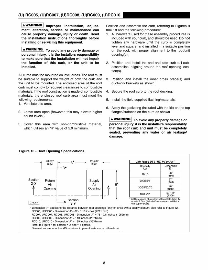
Figure 10 - Roof Opening Specifications
20-7/8"(530)
20-7/8"(530)A*
ReturnAir
Opening
SupplyAir
OpeningE*
SectionY-Y
SectionX-X
Capacity[ CA ]
DimensionE *
10/15
20/25/50
30/35/60/70
40/80/12
26"(660)
37"(940)
48"(1219)
53-1/2"(1359)
Unit Type [ UT ] “RT, PV or AH”
* All Dimensions Shown Have Been Calculated To Include A One (1) Inch Clearance Around Return And Supply Ducts.
CURB SPECIFICATIONS* ROOF OPENINGS
D3809-4
* Dimension “A” applies to the distance between roof openings (only on units with a supply plenum; also refer to Figure 12):RC005, URC005 - Dimension “A”= 87 - 1/16 inches (2211 mm)RC007, URC007, RC008, URC008 - Dimension “A” = 76 - 7/8 inches (1952mm)RC009, URC009 - Dimension “A” = 113 inches (2871mm)RC010, URC010 - Dimension “A” = 139 inches (3531mm)Refer to Figure 4 for section X-X and Y-Y details.Dimensions are in inches (Dimensions in parenthesis are in millimeters).
8

Figure 3 - Roof Curb Kit Assembly** The roof curb and destined unit must be sealed completely to prevent any water or air leakages
(also see Figure 16). Refer to Figures 33 and 34 for Ductwork Mounting Bracket Assembly.
(U) RC005, (U)RC007, (U)RC008, (U)RC009, (U)RC010
9

(U) RC005, (U)RC007, (U)RC008, (U)RC009, (U)RC010
Figure 13 - Detail D Figure 14 - Detail E
Figure 12 - Roof Curb Application (Also refer to Figures 10, 13 and 14)
10

(U) RC005, (U)RC007, (U)RC008, (U)RC009, (U)RC010
Figure 16 - Unit/Curb Rail Assembly For Field Installations: These Cross Brace/CurbAdaptors (two adaptors ship with each rooftop unit) mustbe repositioned when the unit is mounted on a curb orplatform (one for each end). Simply remove the screws,turn the piece over (end for end) and secure in placeusing the holes/hardware provided. All joints andseams must be sealed completely to prevent leaks.
Figure 15 - Curb Specifications
2" (50)
3/8" (10) ClearanceShould Be MaintainedOn Each Side To InsureProper Installation.
1-7/8" (22)
AnchorLocation
* Field SuppliedBy Others
D3809-2
4"(102)
12"(305) Nailer
(Wood Strip)
Nail *
Felt *Cant *
1" (25)Gasketing
Roof
Unit
Seal All Corners,Seams & Gaps.
Unit BaseSide Rail FlangeWith Curb Cap
OptionalInsulation
See Detail K
Detail K
Curb RailAss'y.
Section Curb Side Rail
2-1/2"(64)
Damper
D3809-3
Unit/Base RailAssembly
Curb Cap End Adaptor -Supplied with the Unit(one each end).
11
Replacement Hardware Kit:
(U)RC005, (U)RC007, (U)RC008Part No. RCHK-578
(U)RC009, (U)RC010Part No. RCHK-910

(U) RC011, (U)RC012
Roof Curb for arrangement D include an evaporativecooler platform. See pages 22 and 23.
Roof Curbs ship knocked down for ease of handlingand storage. The field assembly and mounting of thecurb to the roof is the responsibility of the installer. allkits ship complete with pre-assembled side and endrails, cross member supports, ductwork connectorbrackets, hardware, insulation and gasketing. SeeFigure 19, 33 and 34 for a complete parts list for yourkit. Check to see that all components of the kit areincluded. Refer to Figures 17 thru 23, 31 and 32 to seeif all other field supplied parts are also on hand.
Provide a suitable opening in the roof as suggestedper Figure 18 and 20. The return air opening has beencalculated to include a one inch clearance on eachside of the ductwork. The installer may determine theopening to accept a return air duct to suit particularneeds.
1-7/8" Typ.Flange
12"
W Inside
B Outside
1-7/8" Typ.Flange
H Outside
F Inside
Roof Curb Rooftop (RA) Capacity Roof Curb Kit Suffix No. - *Kit No.* Arrangement (CA) * - 1 * - 2 * - 3 * - 4
RC011-* M 20 or 40 NA 85 NA 112
RC012- * P 20 or 40 NA 115 NA 142
APPROXIMATE ROOF CURB KIT WEIGHTS (LBS.)
Figure 17 - Dimensions
DIMENSIONAL DATA
NA=Not Applicable1 lb. = 0.453 Kg(RA) = Rooftop Arrangement(CA) = Capacity
RC011 and RC012 - *Kit No.* CAPACITY W
†B
†F
†H
†
* -2 20 37- 7/16 41- 3/16 41 - 1/2 45 - 1/4(951) (1046) (1054) (1149)
* - 4 40 53-15/16 57-11/16 41 - 1/2 45 - 1/4(1370) (1465) (1054) (1149)
† Dimensions are in inches.(Dimensions in parenthesis are in millimeters.)
12

(U) RC011, (U)RC012
To avoid any property damage orpersonal injury, it is the installers responsibilityto make sure that the installation will not impairthe function of this curb, or the unit to beinstalled.
All curbs must be mounted on level areas. The roof mustbe suitable to support the weight of both the curb andthe unit to be mounted. The enclosed area of the roofcurb must comply to required clearances to combustiblematerials. If the roof construction is made of combustiblematerials, the enclosed roof curb area must meet thefollowing requirements:1. Ventilate this area.
2. Leave area open (however, this may elevate highersound levels.)
3. Cover this area with non-combustible material,which utilizes an “R” value of 5.0 minimum.
Position and assemble the curb, referring to Figures 17thru 23, 33 and 34 Use the following procedure:1. All hardware used for these assembly procedures is
included with your curb, and should be used. Do nottighten any hardware until the curb is completelylevel and square, and installed in a suitable positionon the roof, with proper alignment to the roof/unitopening(s).
2. Position and install the end and side curb rail sub-assemblies, aligning around the roof opening loca-tion(s).
3. Position and install the inner cross brace(s) andductwork brackets as shown.
4. Secure the roof curb to the roof decking.
5. Install the field supplied flashing/materials.
6. Apply the gasketing (included with the kit) on the topflanges/surfaces on the curb as shown
To avoid any property damage orpersonal injury, it is the installer’s responsibilitythat the roof curb and unit must be completelysealed, preventing any water or air leakage/damage.
Figure 18 - Roof Opening Specifications
Unit Type [ UT ] “AH”
* 20-7/8"(530)
E*Return
AirOpening
SectionY-Y
SectionX-X
Capacity[ CA ]
DimensionE *
20
40
37"(940)
53-1/2"(1359)
* All Dimensions Shown Have Been Calculated To Include A One (1) Inch Clearance Around Return Duct.
CURB SPECIFICATIONS* ROOF OPENINGS
D3809-5A
Dimensions are in inches (Dimensions in parenthesis are in millimeters).Refer to Figure 20 for Section X-X and Y-Y details.
13
(U) RC011, (U)RC012
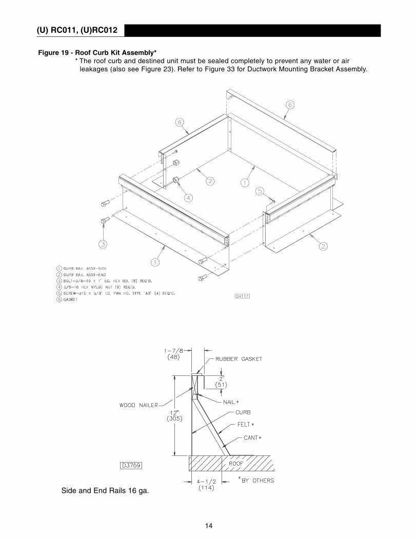
Figure 19 - Roof Curb Kit Assembly** The roof curb and destined unit must be sealed completely to prevent any water or air
leakages (also see Figure 23). Refer to Figure 33 for Ductwork Mounting Bracket Assembly.
Side and End Rails 16 ga.
14

(U) RC011, (U)RC012
Figure 20 - Roof Curb Kit Application (Also refer to Figures 18, 19 and 21)
Figure 21 - Return Air Ductwork Connections
15
(U) RC011, (U)RC012
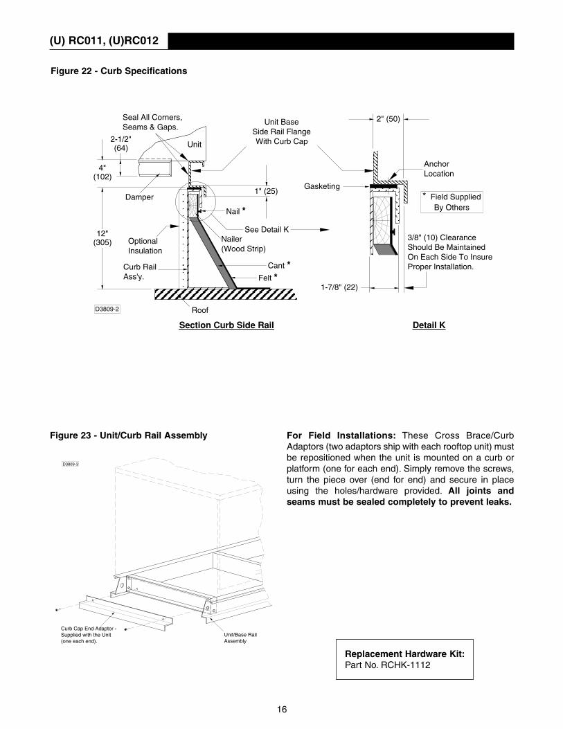
Figure 23 - Unit/Curb Rail Assembly For Field Installations: These Cross Brace/CurbAdaptors (two adaptors ship with each rooftop unit) mustbe repositioned when the unit is mounted on a curb orplatform (one for each end). Simply remove the screws,turn the piece over (end for end) and secure in placeusing the holes/hardware provided. All joints andseams must be sealed completely to prevent leaks.
Figure 22 - Curb Specifications
2" (50)
3/8" (10) ClearanceShould Be MaintainedOn Each Side To InsureProper Installation.
1-7/8" (22)
AnchorLocation
* Field SuppliedBy Others
D3809-2
4"(102)
12"(305) Nailer
(Wood Strip)
Nail *
Felt *Cant *
1" (25)Gasketing
Roof
Unit
Seal All Corners,Seams & Gaps.
Unit BaseSide Rail FlangeWith Curb Cap
OptionalInsulation
See Detail K
Detail K
Curb RailAss'y.
Section Curb Side Rail
2-1/2"(64)
Damper
D3809-3
Unit/Base RailAssembly
Curb Cap End Adaptor -Supplied with the Unit(one each end).
16
Replacement Hardware Kit:Part No. RCHK-1112

(U) RC013
Roof Curbs ship knocked down for ease of handlingand storage. The field assembly and mounting of thecurb to the roof is the responsibility of the installer. Allkits ship complete with pre-assembled side and endrails, cross member supports, hardware, insulation andgasketing. See Figures 26 and 33 for a complete partslist for your curb. Check to see that all components areincluded. Refer to Figurs 26 thru 33 to see if all otherfield supplied parts are also on hand.
Provide a suitable opening in the roof as suggestedper Figures 25 and 27. The return air opening hasbeen calculated to include a one inch clearance oneach side of the ductwork. The installer may determinethe opening to accept a return air duct to suit particularneeds.
1-7/8" Typ.Flange
1-7/8" Typ.Flange
12"
W Inside
B Outside
F Inside
H Outside
1-1/2"Flange
Figure 24 - Dimensions
DIMENSIONAL DATAFor use with air handler “AH” Arrangement “S”
Roof CurbKit No. Lb.s
RC013-2 140
RC013-4 168
RC013 - *Kit No.* CAPACITY W
†B
†F
†H
†
* -2 20 37- 7/16 41- 3/16 38 - 1/8 81 - 7/16(951) (1046) (968) (2069)
* - 4 40 53-15/16 57-11/16 38 - 1/8 81 - 7/16(1370) (1465) (968) (2069)
Approximate Roof Curb Kit Weights
† Dimensions are in inches.(Dimensions in parenthesis are in millimeters.)
17
To avoid any property damage orpersonal injury, it is the installers responsibilityto make sure that the installation will not impairthe function of this curb, or the unit to beinstalled.
All curbs must be mounted on level areas. The roof mustbe suitable to support the weight of both the curb andthe unit to be mounted. The enclosed area of the roofcurb must comply to required clearances to combustiblematerials. If the roof construction is made of combustiblematerials, the enclosed roof curb area must meet thefollowing requirements:1. Ventilate this area.
2. Leave area open (however, this may elevate highersound levels.)
3. Cover this area with non-combustible material,which utilizes an “R” value of 5.0 minimum.
Position and assemble the curb, referring to Figures 1 thru 8, 17 and 18 and the following procedure:1. All hardware used for these assembly procedures is
included with your curb, and should be used. Do nottighten any hardware until the curb is completelylevel and square, and installed in a suitable positionon the roof, with proper alignment to the roof/unitopening(s).
2. Position and install the end and side curb rail sub-assemblies, aligning around the roof opening loca-tion(s).
3. Position and install the inner cross brace(s) andductwork brackets as shown.
4. Secure the roof curb to the roof decking.
5. Install the field supplied flashing/materials.
6. Apply the gasketing (included with the kit) on the topflanges/surfaces on the curb as shown
To avoid any property damage orpersonal injury, it is the installer’s responsibilitythat the roof curb and unit must be completelysealed, preventing any water or air leakage/damage.
(U) RC013
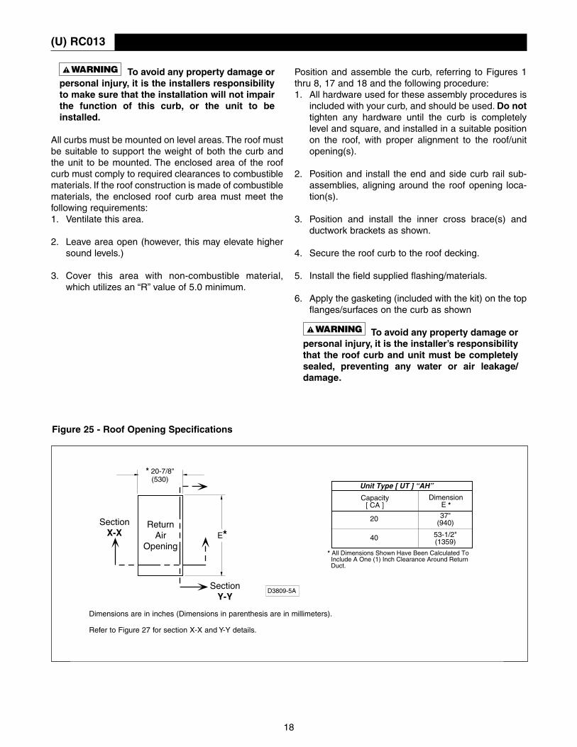
Figure 25 - Roof Opening Specifications
Unit Type [ UT ] “AH”
* 20-7/8"(530)
E*Return
AirOpening
SectionY-Y
SectionX-X
Capacity[ CA ]
DimensionE *
20
40
37"(940)
53-1/2"(1359)
* All Dimensions Shown Have Been Calculated To Include A One (1) Inch Clearance Around Return Duct.
CURB SPECIFICATIONS* ROOF OPENINGS
D3809-5A
Dimensions are in inches (Dimensions in parenthesis are in millimeters).
Refer to Figure 27 for section X-X and Y-Y details.
18

(U) RC013
FIGURE 26 - ROOF CURB KIT ASSEMBLY** The roof curb and destined unit must be sealed completely to prevent any water or air
leakages (also see Figure 30) Refer to Figure 33 for Ductwork Mounting Bracket Assembly.
19

(U) RC013
Figure 27 - Roof Curb Kit Application (Also refer to Figures 25, 26 and 28)
Figure 28 - Return Air Ductwork Connections
20

(U) RC013
Figure 29 - Curb Specifications
Figure 30 - Unit/Curb Rail Assembly For Field Installations: These Cross Brace/CurbAdaptors (two adaptors ship with each rooftop unit) mustbe repositioned when the unit is mounted on a curb orplatform (one for each end). Simply remove the screws,turn the piece over (end for end) and secure in placeusing the holes/hardware provided. All joints andseams must be sealed completely to prevent leaks.
2" (50)
3/8" (10) ClearanceShould Be MaintainedOn Each Side To InsureProper Installation.
1-7/8" (22)
AnchorLocation
* Field SuppliedBy Others
D3809-2
4"(102)
12"(305) Nailer
(Wood Strip)
Nail *
Felt *Cant *
1" (25)Gasketing
Roof
Unit
Seal All Corners,Seams & Gaps.
Unit BaseSide Rail FlangeWith Curb Cap
OptionalInsulation
See Detail K
Detail K
Curb RailAss'y.
Section Curb Side Rail
2-1/2"(64)
Damper
D3809-3
Unit/Base RailAssembly
Curb Cap End Adaptor -Supplied with the Unit(one each end).
21
Replacement Hardware Kit:Part No. RCHK-13

(U) RC015
Module SizeOne size platform fits all Evaporative Cooler Modules,unit capacities 10 through 80.
This platform is shipped knocked down for ease of han-dling and storage. The field assembly and mounting ofthe platform to the roof is the responsibility of theinstaller. This platform ships complete with twoadjustable platform rails and hardware. See the figuresfor a complete parts list for your platform. Check to seethat all components of the platform are included.
Roof CurbKit No. Capacities (CA) Weight (Lbs.)*
RC015-1 10/15 30
RC015-2 20/25/50 30
RC015-3 30/35/60/70 30
RC015-4 40/80 30
*1 Lb. = 0.453 kg
Approximate Roof Curb Kit Weights
Figure 31 - Installation
22
Replacement Hardware Kit:Part No. RCHK-15

(U) RC015
To avoid any property damage orpersonal injury, it is the installers responsibilityto make sure that the installation will not impairthe function of this curb, or the unit to beinstalled.
All platforms must be mounted on level areas. The roofmust be suitable to support the weight of both the plat-form and the unit to be mounted.
Position and assemble the platform, referring to Figures2 and 3, and the following procedure:1. All hardware used for these assembly procedures is
included with your platform, and should be used. Donot tighten any hardware until the platform is com-pletely level and square, and installed in a suitableposition on the roof, with proper alignment to theroof/unit.
2. Position and install the platform rails.
3. Secure the platform to the roof decking.
4. Follow all installation instructions with any other unitthat may be used for this installation.
To avoid any property damage orpersonal injury, it is the installer’s responsibilitythat the roof curb and unit must be completelysealed, preventing any water or air leakage/damage.
1 - Evaporative Cooler Assembly2 - Platform Curb3 - 1/4-20 “keps” nut (8 required)4 - 1/4-20 x 5/8 Ig. hex head bolt (8 required)
Figure 32 - Evaporative Platform Curb to Rooftop Arrangement Installation
23
Duckwork Connections
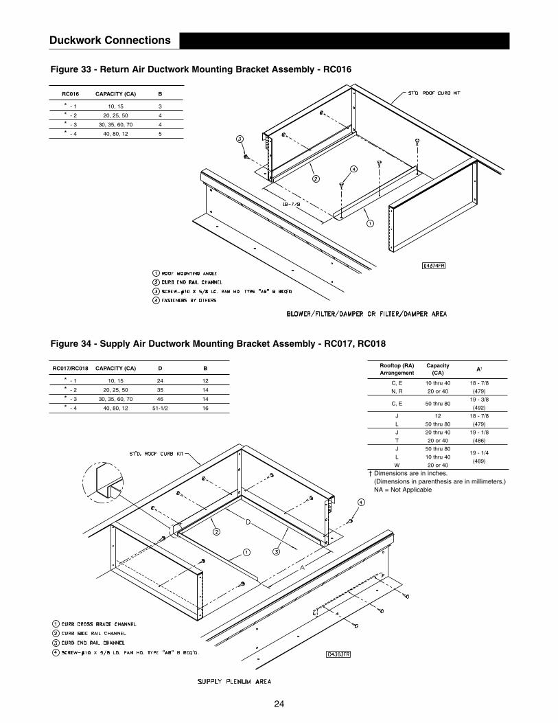
Figure 33 - Return Air Ductwork Mounting Bracket Assembly - RC016
24
Figure 34 - Supply Air Ductwork Mounting Bracket Assembly - RC017, RC018
RC001, RC002, RC003, RC004, & RC006-*RC016 CAPACITY (CA) B
* - 1 10, 15 3
* - 2 20, 25, 50 4
* - 3 30, 35, 60, 70 4
* - 4 40, 80, 12 5
RC001, RC002, RC003, RC004, & RC006-*RC017/RC018 CAPACITY (CA) D B
* - 1 10, 15 24 12
* - 2 20, 25, 50 35 14
* - 3 30, 35, 60, 70 46 14
* - 4 40, 80, 12 51-1/2 16
Roof Curb Rooftop (RA) CapacityA†
H†
Kit No.* Arrangement (CA) (outside) (ins
C, E 10 thru 40 18 - 7/8
N, R 20 or 40 (479) (1807) (17
RC002-*C, E 50 thru 80
19 - 3/8 71 - 1/8 67
(492) (1807) (17
RC003-* J 12 18 - 7/8 97 - 1/8 93
L 50 thru 80 (479) (2467) (23
RC004-* J 20 thru 40 19 - 1/8 97 - 1/8 93
T 20 or 40 (486) (2467) (23
J 50 thru 8019 - 1/4
RC006-* L 10 thru 40 107 - 5/16 103
W 20 or 40(489) (605) (26
† Dimensions are in inches.(Dimensions in parenthesis are in millimeters.)NA = Not Applicable