rotary screw compressors · 2018-12-03 · may show units with optional equipment installed. these...
TRANSCRIPT

S70 - 101 SM/NOV 94
File: SERVICE MANUAL - Section 70Replaces: Nothing (New Information)Dist: 3, 3a, 3b, 3c
Service Manual ROTARY SCREW COMPRESSORS
XJS and XJF 95/120
Prope
rty o
f Am
erica
n Airli
nes

XJS and XJF Rotary Screw CompressorService Manual
S70 - 101 SMPage i
TABLE OF CONTENTS
GENERALGeneral Maintenance ........................................................................................................................................................... 3Preventive Maintenance Inspection .................................................................................................................................... 3Torque Specifications .......................................................................................................................................................... 3Special Tools and Test Equipment ...................................................................................................................................... 4Safety Precautions ................................................................................................................................................................ 4General Safety Practices ....................................................................................................................................................... 4
SECTION 1 – COMPRESSORDisassembly ......................................................................................................................................................................... 5Assembly .............................................................................................................................................................................. 7
SECTION 2 – SHAFT SEALRemoval ............................................................................................................................................................................... 7Installation ........................................................................................................................................................................... 7
SECTION 3 – JACKSHAFT AND GEARSRemoval ............................................................................................................................................................................... 9Installation ......................................................................................................................................................................... 12
SECTION 4 – SLIDE VALVE AND SLIDE STOPRemoval ............................................................................................................................................................................. 13Installation ......................................................................................................................................................................... 15
SECTION 5 – ROTORS AND BEARINGSRemoval ............................................................................................................................................................................. 17Installation ......................................................................................................................................................................... 19
SECTION 6 – COMPRESSOR SUCTION STRAINERRemoval ............................................................................................................................................................................. 24Cleaning and Installation .................................................................................................................................................. 24
APPENDIXTable 1-1. Compressor Clearance Record ......................................................................................................................... 27
FIGURES1-1. Gear Cover, End View .................................................................................................................................................. 51-2. Shaftseal, Jackshaft, Gears, Rotors, and Bearings Sectional View ............................................................................... 61-3. Clamp Collar Installation Tool .................................................................................................................................... 91-4. Slide Valve and Slide Stop Sectional View ............................................................................................................... 101-5. Slide Valve Indicator .................................................................................................................................................. 141-5a. Rotor Discharge Throat Length ................................................................................................................................ 191-5b. Discharge Casing Throat Length .............................................................................................................................. 191-6. Bearing Orientation .................................................................................................................................................... 231-7. Compressor Suction Strainer ...................................................................................................................................... 241-8. Orifice Location Model 95 ......................................................................................................................................... 251-9. Orifice Location Model 120 ....................................................................................................................................... 26
Prope
rty o
f Am
erica
n Airli
nes
S70-101SMPage 3
Frick XJS and XJF Rotary Screw CompressorService Manual
GENERAL
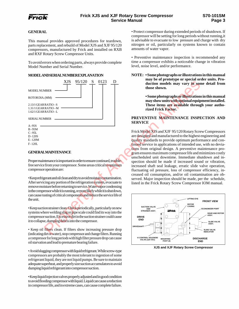
This manual provides approved procedures for teardown,parts replacement, and rebuild of Model XJS and XJF 95/120compressors, manufactured by Frick and installed on RXBand RXF Rotary Screw Compressor Units.
To avoid errors when ordering parts, always provide completeModel Number and Serial Number.
MODEL AND SERIAL NUMBER EXPLANATION
MODEL NUMBER
ROTOR DIA. (MM)
2.13/1 GEAR RATIO – S1.31/1 GEAR RATIO – M1.62/1 GEAR RATIO – L
SERIAL NUMBER
A - 95SB - 95MC - 95LD - 120SE - 120MF - 120L
GENERAL MAINTENANCE
Proper maintenance is important in order to ensure continued, trouble-free service from your compressor. Some areas critical to optimumcompressor operation are:
• Keep refrigerant and oil clean and dry to avoid moisture contamination.After servicing any portion of the refrigeration system, evacuate toremove moisture before returning to service. Water vapor condensingin the compressor while it is running, or more likely while it is shut down,can cause rusting of critical components and reduce the service life ofthe unit.
• Keep suction strainer clean. Check periodically, particularly on newsystems where welding slag or pipe scale could find its way into thecompressor suction. Excessive dirt in the suction strainer could causeit to collapse, dumping debris into the compressor.
• Keep oil filters clean. If filters show increasing pressure drop(indicating dirt or water), stop compressor and change filters. Runninga compressor for long periods with high filter pressure drop can causeoil starvation and lead to premature bearing failure.
• Avoid slugging compressor with liquid refrigerant. While screw-typecompressors are probably the most tolerant to ingestion of somerefrigerant liquid, they are not liquid pumps. Be sure to maintainadequate superheat, and properly size suction accumulators to avoiddumping liquid refrigerant into compressor suction.
• Keep liquid injection valves properly adjusted and in good conditionto avoid flooding compressor with liquid. Liquid can cause a reductionin compressor life, and in extreme cases, can cause complete failure.
XJS 95/120 S 0123 D
• Protect compressor during extended periods of shutdown. Ifcompressor will be setting for long periods without running,itis advisable to evacuate to low pressure and charge with drynitrogen or oil, particularly on systems known to containamounts of water vapor.
• Preventive maintenance inspection is recommended anytime a compressor exhibits a noticeable change in vibrationlevel, noise level, and/or performance.
NOTE: • Some photographs or illustrations in this manualmay be of prototype or special order units. Pro-duction models may vary in some detail fromthose shown.
• Some photographs or illustrations in this manualmay show units with optional equipment installed.These items are available through your autho-rized Frick Factor.
PREVENTIVE MAINTENANCE INSPECTION ANDSERVICE
Frick Model XJS and XJF 95/120 Rotary Screw Compressorsare designed and manufactured to the highest engineering andquality standards to provide optimum performance and con-tinued service in applications of intended use, with no devia-tions from original design. A preventive maintenance pro-gram ensures maximum compressor life and minimizes costlyunscheduled unit downtime. Immediate shutdown and in-spection should be made if increased sound or vibration,increased shaft seal leakage, erratic slide valve operation,fluctuating oil pressure, loss of compressor efficiency, in-creased oil consumption, and/or oil contamination are ob-served. Major inspection should be made, per the schedule,listed in the Frick Rotary Screw Compressor IOM manual.
XJS and XJF Rotary Screw Compressor
DRIVE END
Vi CONTROL SOLENOIDVALVE (120 VAC)
DRIVESHAFT
FRONT VIEW
MOUNTINGFOOT (4)
SUCTION VALVEAND
STRAINER ASSY.
SLIDE VALVEINDICATOR
SLIDE VALVEASSY.
ROTOR CASING
LIFTING EYE
GEAR AND ROTORASSY.
DISCHARGE END
ECONOMIZER PORT
Prope
rty o
f Am
erica
n Airli
nes

S70-101SMPage 4
Frick XJS and XJF Rotary Screw CompressorService Manual
TORQUE DATA
Torque requirements applicable to the procedures contained in thismanual are listed below.
TORQUE SPECIFICATIONS
CAPSCREW SIZETORQUE VALUE
ENGLISH METRIC SOCKET SIZE
M4M5M6M8
M12M16M20M22*
2 ft-lb4 ft-lb7 ft-lb18 ft-lb58 ft-lb
144 ft-lb260 ft-lb368 ft-lb
2.7Nm 5.4 Nm9.5 Nm
24.4 Nm78.7 Nm
195.3 Nm352.5 Nm499 Nm
3 mm4 mm5 mm6 mm10 mm14 mm17 mm32 mm
* Hex HeadNOTE: To convert foot-pounds of torque to metric Newton-meters, mul-tiply foot-pounds times 1.3558 (Example: 75 ft-lbs x 1.3558 equals 101.7Nm)
SAFETY PRECAUTIONS
DANGERS, WARNINGS, CAUTIONS, and NOTES arestrategically placed throughout this manual to further em-phasize the importance of personal safety, qualifications ofuser personnel, and proper use or maintenance of the equip-ment. These precautions supplement and/or complementstandard industry practices and the safety information decalsaffixed to applicable areas of the equipment. Safety Precau-tions are defined as follows:
GENERAL SAFETY PRACTICES
It would be impossible to compile a list of all SafetyPractices applicable to the operation and maintenance of theequipment covered in this manual. This is brought about inpart by the diverse operating environments, as well as thevaried applications and customer-specified configurations.The following Safety Practices are provided as a guide inpromoting safety during routine operation, service, inspec-tion, and maintenance of Frick compressors. This informa-tion, combined with standard industry safety practices, lo-cal, state, and federal regulations, establish the overall safetyrequirements for the workplace.
Always shut down unit and discon-nect power before making any ad-justments or repairs.
Operating a damaged unit is notonly unsafe, but continued use willcause additional damage and/orcomponent failure.
DO NOT attempt any operation orperform any maintenance beforeyou read and understand all SafetyPractices in this manual.
Ensure that work area is ad-equately ventilated, and wearproper safety equipment whencompressor is open to atmosphere.
Indicates an imminently hazardoussituation which, if not avoided, willresult in death or serious injury.
Indicates a potentially hazardoussituation which, if not avoided, couldresult in death or serious injury.
Indicates a potentially hazardoussituation or practice which, if notavoided,will result in damage toequipment and/or minor injury.
Indicates an operating procedure,practice, etc., or portion thereofwhich is essential to highlight.
NOTE:
SPECIAL TOOLS AND TEST EQUIPMENT
Special tools and/or test equipment required to perform themaintenance procedures contained in this manual are listedbelow.
Frick Manufactured
Local Sourced
Owattona Tool Co.Owattona Tool Co.
Local Purchase
Local Purchase
Equipment Manufacturer Part No.
9431123
-
-
Compressor Size 95mm 120mm
Equipment Item No. Item No.
Complete Tool KitWrench, CrowfootWrench, SpannerGear Cover Guide Rod8mm T-wrench8mm Pinion Gear Puller8mm Seal Installation and
Removal Tool8mm Disc Bearing Puller8mm Disc Bearing
Removal Tool8mm Clamping Collar8mm Discharge Bearing
Installation ToolTool Shaft SealScrew, 8mm
534C0008G01111Q0452437111Q0452438534B0192H01534C0456G01534C0521G01534C0523H01
534C0528G01534C0534G01
534C0673G01534D0434G01
534A0310H01111Q0740796
534C0008G02111Q0452437111Q0452440111Q0041972534C0456G01534C0520G01534C0387H01
534C0529G01534C0533G01
534C0673G02534D0435G01
534A0310H02111Q0740796
Bearing PullerRoller Bearing Inner
Race Puller12mm GuidePins
(31/2" lg. and 51/2" lg.)4" Hose Clamp
REPLACE WITH PAGE 2 ON THE PC!
DANGER
WARNING
CAUTION
WARNING
WARNING
WARNING
WARNING
Prope
rty o
f Am
erica
n Airli
nes

S70-101SMPage 5
Frick XJS and XJF Rotary Screw CompressorService Manual
GENERAL SAFETY PRACTICES (CONTD)
1. If you are not familiar with this particular Frick compres-sor, take time to read the operator’s manual (IOM) beforeattempting to run the unit for any purpose.
2. INSPECT COMPRESSOR VISUALLY before start-up.Tighten/replace any loose or missing bolts, nuts, etc. Repairany leaks; replace any damaged hoses, lines, and/or fittings;repair/replace any damaged electrical wiring and/or compo-nents.
3. USE CAUTION PRIOR TO DISASSEMBLY, as com-pressor may still be pressurized. Evacuate compressor inaccordance with S70-101 IOM and applicable Federal, State,and local ordinances, prior to begining any disassembly.
4. DO NOT make adjustments while the unit is operating,unless required for service or maintenance checks.
5. DO NOT operate a damaged compressor. Always com-plete all repairs before running unit.
6. STAY ALERT at all times. Watch what you are doing atall times. Be aware of all persons in the immediate vicinity ofoperating equipment. Allow only authorized personnel in the area.
7. NEVER operate compressor if you are taking medicationthat causes blurred vision, dizziness, drowsiness, or slowedreflexes.
8. DO NOT operate compressor if excessive vibration oc-curs. Immediately shut down unit and complete all necessaryrepairs and required checks before attempting to restart.
9. DO NOT operate compressor exhibiting excessive pres-sure and/or temperature changes. Immediately shut down unitand complete all necessary repairs and functional checksbefore attempting to restart.
10. NEVER alter compressor from original design. Only thosealterations approved by Frick Company and/or performed byauthorized Frick service personnel are permitted.
11. KEEP COMPRESSOR CLEAN, free of debris, andproperly lubricated. A clean, properly lubricated unit willperform more efficiently and operate trouble-free much longer.
REMEMBER: Any piece of equipment is only as safe as those who use and maintain it.
1.0 COMPRESSOR TEARDOWN.
The procedures presented in this manual assume that allmaintenance wil be performed by qualified, Frick-trainedservice personnel equipped with all special tools and testequipment necessary to properly teardown and rebuild ModelXJS and XJF 95/120 compressors.
1.0.1 COMPRESSOR – DISASSEMBLY. Compressor disas-sembly shall be accomplished in the following order:
1. Shaft Seal – Removal (Refer to paragraph 1.1.2).
2. Jackshaft and Gears – Removal (Refer to paragraph1.2.1).
3. Slide Valve and Slide Stop – Removal (Refer to para-graph 1.3.1).
4. Rotors and Bearings – Removal (Refer to paragraph1.4.1).
5. Compressor Suction Strainer – Removal (Refer to paragraph1.5.1).
Figure 1-1. Compressor Gear Cover – End View.
1
23
2
4
1. Seal Housing2. Elbow3. Oil Supply Line4. Gear Cover
XJS and XJF 95 weigh 500 lb.(227kg);XJS and XJF 120 weigh 750lb.(340 kg). Ensure that rigging isproperly attached and secure beforelifting compressor.
WARNING
Prope
rty o
f Am
erica
n Airli
nes

S70-101SMPage 6
Frick XJS and XJF Rotary Screw CompressorService Manual
12
35
7
46
8
109
11 1213 14
15 1617 18
1920
21
22
5823
24
25
2627
2829
30
31
27
3233
34 3536 27 37 3938
40
41
27
42 43
44
36
35 2626
59
25
2423
4645
2048
4950
51
52
53754
557
57
56
1. J
acks
haft
2. C
lam
p C
olla
r3.
Sea
l Sea
r B
acku
p R
ing
4. S
eal H
ousi
ng5.
O-R
ing
6. S
haft
Sea
l Ass
embl
y7.
Soc
ket H
ead
Cap
scre
w8.
O-R
ing
9. F
our-
Poi
nt C
onta
ctB
all B
earin
g10
. Dow
el P
in T
aper
ed11
. Rol
ler
Bea
ring
12. R
etai
ning
Rin
g
13. B
earin
g S
pace
r14
. Gea
r S
et15
. Ret
aini
ng R
ing
16. B
earin
g S
pace
r17
. Rol
ler
Bea
ring
18. R
etai
ning
Rin
g19
. Rol
ler
Bea
ring
20. S
prin
g P
in21
. Mal
e In
let B
ushi
ng22
. Rot
or C
asin
g23
. O-R
ing
24. G
as S
eal
25. R
olle
r B
earin
g26
. Ang
ular
Con
tact
Bal
l Bea
ring
27. O
-Rin
g28
. Pip
e P
lug
29. O
-Rin
g30
. Bal
ance
Pis
ton
Sle
eve
31. W
ave
Spr
ing
32. B
earin
g S
pace
r33
. Bal
ance
Pis
ton
34. F
our-
Poi
nt C
onta
ctB
all B
earin
g35
. Loc
kwas
her
36. L
ockn
ut37
. Com
pres
sion
Spr
ing
38. M
ale
Dis
tanc
e S
leev
e39
. Out
let B
ore
Cov
er40
. Spr
ing
Pin
41. O
utle
t Bor
e C
over
42. W
ave
Spr
ing
43. D
isch
arge
Cas
ing
44. F
emal
e D
ista
nce
Sle
eve
45. O
-Rin
g46
. Dow
el P
in47
. Fin
ishe
d R
otor
Pai
r48
. Fem
ale
Inle
t Bus
hing
49. R
olle
r B
earin
g50
. Ret
aini
ng R
ing
51. O
-Rin
g52
. Gea
r C
over
53. S
olen
oid
Val
ve G
aske
t54
. Soc
ket H
ead
Cap
scre
w55
. Sol
enoi
d V
alve
56. O
il In
let
57. D
owel
Pin
58. D
owel
Pin
59. S
him
.002
"
Figure 1-2. Shaft Seal, Jackshaft, Gears, Rotors and Bearings Sectional View.
Prope
rty o
f Am
erica
n Airli
nes

S70-101SMPage 7
Frick XJS and XJF Rotary Screw CompressorService Manual
SEAL SEAT
8. Place seal housing (4) on workbench with inboard sidefacing down; using Seal Installation and Removal Tool, push(with hand pressure only) carbon-faced seal assembly outof housing.
SEAL HOUSING
SEAL REMOVALAND INSTALLATION
TOOL
1.0.2 COMPRESSOR – ASSEMBLY. Compressor assem-bly shall be accomplished in the following order:
1. Compressor Suction Strainer Cleaning and Installation(Refer to paragraph 1.5.2).
2. Rotors and Bearings – Installation (Refer to paragraph 1.4.2).
3. Slide Valve and Stop – Installation (Refer to paragraph 1.3.2).
4. Jackshaft and Gears – Installation (Refer to paragraph 1.2.2).
1.1.1 SHAFT SEAL REPLACEMENT. This procedureprovides the information necessary for qualified personnel toreplace the jackshaft carbon-faced seal, including requiredcompressor disassembly.
1.1.2 SHAFT SEAL – REMOVAL. Shaft seal removal shallbe accomplished as follows:
NOTE: Index numbers refer to Figure 1-2, unless other-wise noted.
1. Evacuate compressor and oil separator (refer to S70-101IOM).
2. Remove flexible drive coupling (refer to S70-101 IOM).
3. Loosen oil supply line nuts at elbows (2, Figure 1-1), whichare located on seal housing and gear cover.
4. Loosen hex-head screw in clamp collar (2); remove clampcollar and seal seat backup ring (3) from jackshaft (1).
5. Remove capscrews (7) securing seal housing (4) to gearcover (52). Remove seal housing and seal housing o-ring (8).A small amount of oil will drain from housing.
NOTE: Provisions should be made to catch residualoil that will drain when seal housing is removed.
6. Remove seal housing oil supply tubing (3, Figure 1-1).
7. Remove rotating seal seat portion (Figure 1-1) of shaft sealassembly (6) from jackshaft (1).
CLAMP COLLAR
9. Remove carbon-faced seal assembly o-ring (5) from sealhousing.
10. Remove oil supply line elbow (2, Figure 1-1) from sealhousing.
1.1.3 SHAFT SEAL – INSTALLATION. Shaft seal instal-lation shall be accomplished as follows:
NOTE: Index numbers refer to Figure 1-2, unless other-wise noted.
Avoid damaging carbon-faced sealand rotating seal seat. Mishandlingwill shorten seal life. Do not touchsealing surfaces. Surfaces can beblemished by perspiration. Ensurethat carbon is not chipped or cracked.
1. Clean jackshaft; polish minor scratches with crocus cloth,wipe clean and coat shaft with clean refrigerant oil. Ensurethat keyway edges are free burrs.
2. Before installing rotating seal seat, coat seat surface withclean refrigerant oil.
3. With shiny side of seal seat facing out, coat seat withrefrigerant oil and slide over jackshaft. Do not damage o-ring.(Photo 4-24, page 6)
CAUTIONPrope
rty o
f Am
erica
n Airli
nes

S70-101SMPage 8
Frick XJS and XJF Rotary Screw CompressorService Manual
8. Install oil line elbow (2, Figure 1-1) in seal housing.
9. Install oil supply tubing (3, Figure 1-1) on elbow locatedon gear cover.
10. Place new o-ring (8) on seal housing and install sealhousing over jackshaft, using care not to damage carbon-faced seal.
11. Install end of oil supply tubing into elbow on sealhousing, ensuring that roll pin (57) in gear cover (52)engages hole in seal housing; align elbow with oil supplyline, as necessary.
12. Secure seal housing to gear cover with capscrews (7);tighten capscrews evenly, in crisscross pattern, to a torquevalue of 58 foot-pounds (79 Nm).
13. Tighten nuts at elbows of oil supply line (2, Figure 1-1),which are located on seal housing and gear cover.
14. Install seal seat backup ring (3) and clamp collar (2) overjackshaft (1) and against rotating seal seat.
OIL STRAINER
7. Install new oil strainer, p/n 534A0342H01, in gear cover oilsupply line elbow port.
4. Place seal housing on workbench, with outboard side down.Coat new o-ring with clean refrigerant oil; install o-ring ingroove in seal housing, located in stationary carbon bore.
5. Coat carbon-faced seal with clean refrigerant oil.
6. Carefully place carbon-faced seal assembly, with carbonend up, in seal housing. Using nonmetallic Seal InstallationTool and being careful not to touch carbon, push seal assembly(hand pressure only) into seal housing until it is evenlyseated, with no gap between seal and housing.
NON-METALLICSEAL INSTALLATION
TOOL
CARBON-FACEDSEAL
SEAL SEAT
JACKSHAFT
Before installing seal housing, en-sure that feed hole below elbow isfree of obstructions.
SEAL SEATBACKUP RING
CLAMP COLLAR
15. Using Clamp Collar Installation Tool, tighten clampcollar and seal seat backup ring against rotating seal seat toa torque value of 30 foot-pounds (40.7 Nm). (See Figure 1-3.)
16. Tighten collar Allen-head bolt; remove Installation Tool.
CLAMP COLLARINSTALLATION
TOOL
17. Install flexible drive coupling. (Refer to S70-101 IOM.)
18. Evacuate compressor and oil separator. (Refer to S70-101 IOM.)
CAUTION
Prope
rty o
f Am
erica
n Airli
nes

S70-101SMPage 9
Frick XJS and XJF Rotary Screw CompressorService Manual
Figure 1-3. Using Clamp Collar Installation Tool.
1.2 JACKSHAFT AND GEARS. This procedure provides theinformation necessary for qualified personnel to replace thejackshaft bearings, including required compressor disassembly.
1.2.1 JACKSHAFT AND GEARS – REMOVAL. Jackshaftremoval shall be accomplished as follows:
NOTE: Index numbers refer to Figure 1-2, unless other-wise noted.
1. Place suitable drain pan under compressor oil drain, removedrain plug located at the center bottom on the gear cover anddrain plug (24, Figure 1-4).
2. Remove shaft seal. (Refer to paragraph 1.1.2.)
3. Place suitable drain pan under slide stop cover (30, Figure1-4) and remove capscrews (7) securing slide stop cover togear cover (2, Figure 1-4); remove slide stop cover and o-ring(32, Figure 1-4), while holding stepper piston in by hand.
8MM T-WRENCH
STEPPER PISTON
5. Remove stepper piston with glyd-rings (10 and 28, Figure1-4) and o-rings (11 and 29, Figure 1-4). If glyd-rings and o-rings are to be replaced, cut glyd-rings off of stepper pistonusing knife and remove and discard o-rings.
4. Thread 8mm T-wrench into stepper piston and push pistonin against spring force. With finger through oil drain hole (24,
STEPPER PISTON
Figure 1-4), push in against spring force and feel along bottomof slide stop. When threaded hole in slide stop is located, insert8mm screw (Frick p/n 111Q0740796) through oil drain holeand thread into slide stop.
4
21 13
12
10
98
7 3
5
6
11
1. O-Ring2. Carbon Face3. Rotating Seal Seat Assembly with shiny side of seat facing outward4. O-Ring5. Gear Cover6. Four-Point Contact Ball Bearing7. Clamp Collar Installation Tool8. Shaft9. Clamp Collar10. Seal Seat Backup Ring11. Seal Housing12. Carbon Faced Seal Assembly13. Strainer
Prope
rty o
f Am
erica
n Airli
nes

S70-101SMPage 10
Frick XJS and XJF Rotary Screw CompressorService Manual
31
32111
23
10
3029
2827
1011 26
1110
2524
23
221
2120
1933
18
17
1516
81411
1210
9
8
7
65
4
1. S
ocke
t Hea
d C
apsc
rew
2. G
ear
Cov
er3.
Rot
or C
asin
g4.
Pip
e P
lug
1/4
x 18
NP
TF
5. S
ocke
t Hea
d C
apsc
rew
6. S
prin
g P
in .1
25 x
.375
7. D
isch
arge
Cas
ing
8. S
ocke
t Hea
d C
apsc
rew
9. S
prin
g P
in .1
87 x
.625
10. G
lyd-
Rin
g11
. O-R
ing
12. O
-Rin
g14
. Cyl
inde
r C
over
15. S
lyd-
Rin
g16
. Che
ck V
alve
Ret
aine
r17
. Int
erna
l Che
ck V
alve
18. O
-Rin
g19
. Slid
e V
alve
Pis
ton
20. F
aste
ner
for
1921
. Slid
e V
alve
22. U
nloa
der
Spr
ing
23. S
prin
g S
uppo
rt24
. Pip
e P
lug
25. S
lide
Sto
p26
. Slid
e S
top
Pis
ton
27. S
tepp
er P
isto
n28
. Gly
d-R
ing
29. O
-Rin
g30
. Slid
e S
top
Cov
er31
. Key
32. O
-Rin
g33
. Was
her
Figure 1-4. Slide Valve and Slide Stop Sectional View.
Prope
rty o
f Am
erica
n Airli
nes

S70-101SMPage 11
Frick XJS and XJF Rotary Screw CompressorService Manual
6. Thread T-wrench into slide stop piston (26, Figure 1-4);remove slide stop piston with glyd-ring (10, Figure 1-4) ando-ring (11, Figure 1-4). If glyd-ring and o-ring are to bereplaced, cut glyd-rings off of stepper piston using knife andremove and discard o-rings.
10.With gear cover elevated on wood blocks, remove jackshaftand gear assembly from cover by tapping on outboard end ofjackshaft with rubber mallet; remove jackshaft, gear assem-bly, and outboard section of inner race of four-point contactball bearing (9).
JACKSHAFT
11. Remove remaining section of four-point bearing fromgear cover.
12. Remove retaining ring (12) from gear cover using screw-driver.
RETAINING RING
13. Remove outer race of roller bearing (11) from gear caseusing Bearing Puller (Owattona Tool Co. p/n 943).
BEARING PULLER
NOTE: If replacement Jackshaft Kit is used, steps 14through 16 do not apply.
SLIDE STOP PISTON
7. Remove two capscrews (1) from opposite sides of gearcover (2). Install two 12mm guide pins (3 1/2-inches long).
8. Remove remaining capscrews from gear cover. Thread two12mm capscrews into jacking holes in gear cover and spreadcover away from rotor casing (3). Hold on to jackshaft andremove gear cover and o-ring (51).
9. Attach Pinion Gear Puller to pinion gear (14); removepinion gear from male rotor (47).
PINION GEAR PULLER
12MM GUIDE PINS
Prope
rty o
f Am
erica
n Airli
nes

S70-101SMPage 12
Frick XJS and XJF Rotary Screw CompressorService Manual
1.2.1 JACKSHAFT AND GEARS – REMOVAL. (CONTD)
14. If necessary, remove inner race of roller bearing (11) fromjackshaft using Bearing Inner Race Puller (Owattona Tool Co.p/n 1123).
6. Install retaining ring (12) in gear cover (52).
Ensure that tool is against outerrace and not against cage and bear-ing rollers.
7. Install outer race of roller bearing (11) in gear cover.Bearing can be installed by freezing and installing it in gearcover or by using Discharge Ball Bearing Installation Tooland rubber mallet. Ensure that roller bearing is tight againstretaining ring (12).
8. Slide jackshaft and gear set assembly (14) into gear coveruntil inner race of roller bearing is seated under the rollersof inner race bearing.
9. Using Jackshaft Bearing Installation Tool, press inboardhalf of four-point contact ball bearing (9) inner race againstinner race of roller bearing (11).
DISCHARGEBALL BEARING
INSTALLATION TOOL
JACKSHAFT AND GEARASSEMBLY
JACKSHAFT BEARINGINSTALLATION TOOL
5. Heat inner race of roller bearing (11) to 250�F (121�C) forone hour, and install race on jackshaft. Push inner race againstbearing spacer (13) and hold in place until bearing cools andgrips jackshaft.
Protective, heat-resistant glovesmust be worn when installing bear-ing inner race.
3. Heat inner race of roller bearing (17) to ����F (232�C) for onehour, and install race on jackshaft. Push inner race against bearingspacer (16) and hold in place until race cools and grips jackshaft.
4. Install outer race of bearing (17) in rotor casing (22); securewith retaining ring (15).
Protective, heat-resistant glovesmust be worn when installing bear-ing inner race.
15. If necessary, remove inner race of roller bearing (17) fromjackshaft using Bearing Inner Race Puller.
16. Remove bearing spacer (16) from jackshaft.
17. Remove retaining ring (15) and outer race of roller bearing(17) from rotor casing (22).
1.2.2 JACKSHAFT AND GEARS – INSTALLATION.Jackshaft and gears installation shall be accomplished as follows:
NOTE: Index numbers refer to Figure 1-2, unless other-wise noted.
1. Thoroughly clean all parts with OSHA approved, nonflam-mable degreaser and clean, lint-free rags.
NOTE: If replacement Jackshaft Kit is used, steps 2through 5 do not apply.
NOTE: In preparation for installing pinion gear instep 12 heat gear to maximum 450�F (121�C) for approxi-mately three hours..
2. Install bearing spacer (16) onto jackshaft (1) against maingear (14).
CAUTION
WARNING
WARNING
Prope
rty o
f Am
erica
n Airli
nes

S70-101SMPage 13
Frick XJS and XJF Rotary Screw CompressorService Manual
10. Press outer race of four-point bearing into gear cover,using seal housing (4); remove seal housing.
11. Using Jackshaft Bearing Installation Tool , press outboardhalf of four-point contact ball bearing (9) inner race in place.
Protective, heat-resistant glovesmust be worn when installing bear-ing inner race.
DO NOT force pinion gear into po-sition. If pinion gear does not seatproperly on first attempt, remove,reheat, and reinstall.
12. Install heated pinion gear on male rotor shaft (17). Pushpinion gear against shaft shoulder; hold in place until gearcools and grips jackshaft.
PINION GEAR
13. Lubricate all internal compressor parts with a thin coat ofclean refrigerant oil.
NOTE: If 12mm guide pins were taken out after gearcover was removed, reinstall pins in opposite sides ofcasing, to facilitate cover installation.
14. Install new o-ring (51) in drive-end of rotor casing; use alight coating of grease to hold o-ring place
It is important that jackshaft ro-tates when cover is installed. If shaftdoes not rotate, it may be bindingin roller bearing.
15. Install the gear cover and secure in place with capscrews(7); tighten capscrews to a torque value of 58 foot-pounds (79Nm). Remove guide pins.
Protective, heat-resistant glovesmust be worn when installing glyd-ring.
Place section of shim material on in-side of hose clamp to prevent pos-sible damage caused by clamp holes.
16. If previously removed, install o-ring (11, Figure 1-4) andglyd-ring (10, Figure 1-4) on slide stop piston (26, Figure 1-4). To install glyd-ring, heat to 250�F (121�C) for one hourand push into slot. Use a 4-inch (10 cm) hose clamp to holdglyd-ring in place for 10 minutes.
Protective, heat-resistant glovesmust be worn when installing bear-ing inner race.
18. Place slide stop piston inside stepper piston. Thread 8mmT-wrench into stepper piston; install stepper piston and slidestop piston in compressor.
STEPPER PISTON
8MM T-WRENCH
19. Push stepper piston against spring force and remove 8mmscrew previously threaded into slide stop through drain hole;keep hand pressure against piston and remove T-wrench.
20. Position slide stop cover (30, Figure 1-4), with new o-ring(32, Figure 1-4) on gear housing (2, Figure 1-4); secure slidestop cover to gear housing with capscrews (1). Tightencapscrews to a torque value of 58 foot-pounds (79 Nm).
21. Install compressor drain plug (24, Figure 1-4).
22. Install flexible drive coupling. (Refer to S70-101 IOM.)
23. Evacuate compressor and oil separator. (Refer to S70-101IOM.)
1.3 SLIDE VALVE AND SLIDE STOP. This procedureprovides the information necessary for qualified personnel toreplace the slide valve piston glyd-rings, including requiredcompressor disassembly.
1.3.1 SLIDE VALVE AND SLIDE STOP – REMOVAL.Slide valve and slide stop removal shall be accomplished asfollows:
NOTE: Index numbers refer to Figure 1-4, unless otherwise noted.
1. Evacuate compressor and oil separator. (Refer to S70-101IOM.)
2. Remove coupling guard, if necessary.
3. Place suitable drain pan under compressor and remove oildrain plug (24).
There is spring force behind slidestop cover. Hold stepper piston (27)in by hand.
WARNING
CAUTION
CAUTION
CAUTION
WARNING
WARNING
CAUTION
Prope
rty o
f Am
erica
n Airli
nes

S70-101SMPage 14
Frick XJS and XJF Rotary Screw CompressorService Manual
7. Thread T-wrench into slide stop piston (26); removepiston with its glyd-ring and o-ring. If glyd-ring and o-ringare to be replaced, cut glyd-ring off of slide stop piston andremove o-ring with a knife.
SLIDE STOP PISTON
8. Remove compressor slide valve indicator position switchcover; remove slide valve position switch.
9. Remove rod guide (5, Figure 1-5) with o-rings (2 and 3,Figure 1-5), indicator rod spring (4, Figure 1-5), and indica-tor rod (6, Figure 1-5); remove o-rings from rod guide.
10. Thread T-wrench into slide stop (25). While pushing inagainst spring pressure, remove 8mm screw (threaded intoslide stop) through oil drain hole; remove slide stop.
Figure 1-5. Slide Valve Indicator.
1
9
2
3
4
5
6
7
8
1. Wiring Connection2. O-Ring3. O-Ring4. Indicator Rod Spring5. Rod Guide6. Indicator Rod7. Slide Valve Piston8. Cylinder Cover9. Discharge Casing
4. Place suitable drain pan under slide stop cover (30); removecapscrews (7, Figure 1-2) securing slide stop cover to gearhousing (2). Remove slide stop cover and o-ring (32).
5. Thread 8mm T-wrench into stepper piston and push pistonin against spring force. With finger through oil drain hole,push in against spring force and feel along bottom of slidestop. When threaded hole in slide stop is located, insert an8mm screw through oil drain hole and thread into slide stop.
STEPPER PISTON
8MM T-WRENCH
6. Remove stepper piston with its glyd-rings (10 and 28) ando-rings (11 and 29). If glyd-rings and o-rings are to bereplaced, cut glyd-ring off of stepper piston and remove o-ringwith a knife.
Prope
rty o
f Am
erica
n Airli
nes

S70-101SMPage 15
Frick XJS and XJF Rotary Screw CompressorService Manual
11. Remove unloader spring (22) and spring support (23).
12. Disconnect 1/4-inch capacity control oil line from con-nector located on cylinder cover (14).
13. Remove capscrews (8) securing cylinder cover to dis-charge casing (7); remove cylinder cover and o-ring (12).
14. Using handle of a rubber mallet, push on slide valve (21)from drive end of compressor. Slide valve piston (19) willemerge from casing.
15. On older units, use a 11/4-inch wrench to unthread slidevalve piston from slide valve; remove slide valve piston withits glyd-rings (10 and 15) and o-ring (11). If glyd-rings ando-ring are to be replaced, cut glyd-rings off of slide valvepiston and remove o-ring with a knife.
SLIDE VALVE PISTON
Protective, heat-resistant gloves mustbe worn when installing glyd-rings.
NOTE: If glyd-rings were not removed from slide valvepiston, proceed to step 8.
4. If previously removed, install new o-ring (11) and glyd-rings (10 and 15) on slide valve piston. To install glyd-rings,heat to 250�F (121�C), and push into slot. Install glyd-ringportion of the piston into piston bore for 10 minutes to ensureglyd-ring is set.
NOTE: Newer compressors require an allen wrench toremove M10 capscrew securing slide valve to piston. (20,Figure 1-4)
16. Remove check valve retainer (16), internal check valve(17), and o-ring (18) from slide valve piston (19), using ascrewdriver.
17. Push slide valve (21) out of drive end of compressor.
NOTE: If further teardown of compressor is required,continue to paragraph 1.4.1.
1.3.2 SLIDE VALVE AND SLIDE STOP – INSTALLA-TION.
NOTE: During reassemble of the compressor it is nec-essary to determine if the slide valve has excessive wear.Excessive wear is defined as the slide valve being able tomove upward into the rotor bore above flush. The pro-cedure to determine excessive movement is as follows.
1. Insert the slide valve into the s.v. bore of the rotor hous-ing. Without installing the rotors, install the discharge hous-ing to the rotor housing. Secure the discharge housing withtwo cap screws and insert dowel pins.
2. By inserting your hands through the suction ports, movethe s.v. into the discharge port so that the s.v. guidesare securing the s.v. in place.
3. Push against the side of the slide valve with one hand andby using either a thin feeler gauge or fingernail, determine ifthe slide valve moves into the rotor bore. The slide valveshould not rise above the bore.
If the slide valve does move into the rotor bore, it may benecessary to replace either the slide valve, the discharge hous-ing, or both. Because the slide valve guides on the dischargehousing are machined oversized , the slide valve must be handfitted to the discharge housing. Use the following procedurewhen new parts are required.
1. Install the slide valve in the rotor housing. Without install-ing the rotors, install the discharge housing with twocapscrews and dowel pins.
2. After inserting your hands through the suction ports, movethe slide valve into the discharge housing. The slide valvewill get tight within the guides. Pull the slide valve completelyout of the discharge port. Using sand paper, lightly sand theslide valve guides on the discharge housing. The process ofsanding the guides must be done with care. Ensure that thesanding is conducted evenly across the guides and removeonly a small amount of material before checking the fit. Ifexcessive material is removed from the guides, the slide valvewill move into the rotor bore.
3. The slide valve is correctly fitted when it is able to movesmoothly in and out of the guides a~ without moving into therotor bore.
Slide valve and slide stop installation shall be accomplished asfollows:
NOTE: Index numbers refer to Figure 1-4, unless other-wise noted.
1. Thoroughly clean all parts with OSHA approved, nonflam-mable degreaser and clean, lint-free rags.
2. Lubricate all internal compressor parts with a coat of cleanrefrigerant oil.
3. Install slide valve (21) into drive end of compressor.
WARNING
Prope
rty o
f Am
erica
n Airli
nes

S70-101SMPage 16
Frick XJS and XJF Rotary Screw CompressorService Manual
18. If previously removed, install o-rings (11 and 29) andglyd-rings (10 and 28) on stepper piston (27). To installglyd-ring, heat to 250�F (121�C) for one hour and push intoslot. Use a 4-inch (10 cm) hose clamp, with solid shimmaterial in I.D., to hold glyd-rings in place for 10 minutes.
19. Place slide stop piston inside stepper piston. Thread 8mmT-wrench into stepper piston; install stepper piston and slidestop piston in compressor.
5. Insert 10M x 1.5 capscrew (20, Figure 1-4) into slide valvepiston; insert assembly into discharge housing and tighten capscrew.
6. Before fully tightening capscrew, push slide valve pistoninto bore, so that glyd-rings are positioned within bore area;tighten capscrew to a torque value of 30 foot-pounds (41 Nm).
7. Using handle of a rubber mallet, push piston into bore until itstops, allowing spring to push piston out. Repeat this step 10-15times to ensure piston moves back and forth freely. If piston doesnot move freely, loosen capscrew and rotate piston within bore90 degrees; tighten capscrew and recheck piston for freedom ofmovement. Repeat step as required until piston moves freely.Apply a small amount of Loctite on cap screw threads.
8. Install new o-ring (18), internal check valve (17), withconical end facing outboard, and check valve retainer (16) inslide valve piston (19).
SLIDE VALVE PISTON
11. Install unloader spring (22), spring support (23), and slidestop (25). Thread 8mm T-wrench into slide stop, pushing slidestop against spring force. With finger through oil drain hole,push in against spring force and feel along bottom of slidestop. When threaded hole in slide stop is located, insert an8mm screw (Frick p/n 111Q0740796) through oil drain holeand thread into slide stop.
9. If previously removed, install o-ring (11) and glyd-rings (10and 15) on slide valve piston. To install glyd-ring, heat to250�F (121�C) and push into slot. Use a 4-inch (10 cm) hoseclamp to hold glyd-rings in place for 10 minutes.
10. For old style piston: Through drive end of compressor,apply pressure to slide valve with handle of rubber mallet andinstall slide valve piston into discharge end of compressor.Thread piston into slide valve; tighten by using 11/4-inchwrench on flats located on end of slide valve piston.
12. Using handle of rubber mallet, push in on end of slide valvepiston against spring ; release pressure several times to ensurethat slide valve and slide valve piston “slide” smoothly. If pistondoes not move smoothly, look for a problem or defect with glyd-ring.
13. Place new o-ring (12) on cylinder cover (14); secure cyl-inder cover to discharge casing (7) with capscrews (8). Tightencapscrews to a torque value of 18 foot-pounds (24.5 Nm).
14. Connect 1/4-inch capacity control oil line to connectorlocated on cylinder cover.
15. Install new o-rings (2 and 3, Figure 1-5) on rod guide (5,Figure 1-5). Install indicator rod spring (4, Figure 1-5) andindicator rod (6, Figure 1-5) into rod guide; thread rod guideinto discharge casing (9).
16. Install compressor slide valve indicator position switchand slide valve indicator position switch cover.
SLIDE STOP PISTON
STEPPER PISTON
Protective, heat-resistant gloves mustbe worn when installing glyd-rings.
17. If previously removed, install o-ring (11) and glyd-ring(10) on slide stop piston (26). To install glyd-ring, heat to250�F (121�C) for one hour and push into slot. Use a 4-inch(10 cm) hose clamp, with solid shim material in I.D., to holdglyd-rings in place for 10 minutes.
Protective, heat-resistant gloves mustbe worn when installing glyd-rings.
Protective, heat-resistant gloves mustbe worn when installing glyd-rings.WARNING
WARNING
WARNING
Prope
rty o
f Am
erica
n Airli
nes

S70-101SMPage 17
Frick XJS and XJF Rotary Screw CompressorService Manual
20. Push stepper piston against spring and remove 8mm screwthreaded into slide stop (25), through oil drain hole; with handpressure against piston, remove T-wrench.
STEPPER PISTON
8MM T-WRENCH
21. With new o-ring (32) on slide stop cover (30), securecover to gear housing with capscrews (7, Figure 1-2). Tightencapscrews to a torque value of 58 foot-pounds (79 Nm).
22. Install drain plug (24, Figure 1-4).
23. Install coupling guard, if previously removed.
24. Evacuate compressor and oil separator. (Refer to S70-101 IOM.)
1.4 ROTORS AND BEARINGS. This procedure providesthe information necessary for qualified personnel to replacethe discharge bearing assembly, including required compres-sor disassembly.
1.4.1 ROTORS AND BEARINGS – REMOVAL. Rotorsand bearings removal shall be accomplished as follows:
NOTE: Index numbers refer to Figure 1-2, unless other-wise noted.1. Remove shaft seal. (Refer to paragraph 1.1.2)
2. Remove jackshaft and gears. (Refer to paragraph 1.2.1)
3. Remove slide valve and stop. (Refer to paragraph 1.3.1)
4. Remove capscrews (8, Figure 1-4) securing outlet borecover (39) to discharge casing (43); remove outlet bore coverwith o-ring (27) and nine compression springs (37).
5. Remove capscrews (8, Figure 1-4) securing outlet borecover (41) to discharge casing; remove outlet bore cover witho-ring; remove spring washer (42), or wave spring on newerunits.
6. Remove male distance sleeve (38) and female distancesleeve (44).
7. At nondrive end of male and female rotor shafts (47), bendone tab back on each lockwasher (35) that was previouslybent into recess of its respective locknut (36).
8. While holding male rotor stationary and with 12mm T-wrench threaded into drive end of male rotor shaft, removelocknut (36) using Spanner Wrench; remove and discardlockwasher (35).
9. While holding female rotor stationary and with 12mm T-wrench threaded into drive end of female rotor shaft, removelocknut (36) using Spanner Wrench; remove and discardlockwasher (35).
11. Remove two capscrews (1 and 5, Figure 1-4) fromopposite sides of discharge casing and install two 12mmguide pins (3 1/2-inches and 5 1/2-inches long); remove rest ofcapscrews securing discharge casing to rotor casing (3).
10. Install an eyebolt into top of discharge casing; attachsuitable lifting sling to hoist with adequate capacity tosupport weight of discharge casing.
EYEBOLT
D I S C H A R G ECASING
XJS and XJF 95 discharge casingweigh 90 lb. (41kg); XJS and XJF120 weigh 115 lb. (53 kg). Ensurethat rigging is of adequate capacityand properly attached before liftingcompressor.
WARNING
Prope
rty o
f Am
erica
n Airli
nes

S70-101SMPage 18
Frick XJS and XJF Rotary Screw CompressorService Manual
12. Install Discharge Ball Bearing Removal Tool on nondriveend of male rotor shaft. Turn jacking screw clockwise toremove four-point contact ball bearing (34) and angle con-tact ball bearings (26) off of shaft, as discharge casingseparates from rotor casing (3)
JACKING SCREW(DISCHARGE BALL BEARING
REMOVAL TOOL)
NON-DRIVE ENDMALE ROTOR SHAFT
MALE DISCHARGE BEARINGAND BALANCE PISTON GROUP
14. Remove four-point contact ball bearing (34), balancepiston (33), wave spring (31), bearing spacer (32), balancepiston sleeve (30), angular contact bearings (26), and shims,if used, from male rotor bore in discharge casing. Label anyshims to permit reinstallation in correct bore. Remove o-rings(27 and 29) from balance piston and balance piston sleeve.
13. Install Discharge Ball Bearing Removal Tool on nondriveend of female rotor shaft. Turn jacking screw clockwise toremove angular contact ball bearings from shaft. When jack-ing screw bottoms, remove tool..
NON-DRIVE ENDFEMALE ROTOR SHAFT
JACKING SCREW(DISCHARGE BALL BEARING
REMOVAL TOOL)
FEMALE DISCHARGEBEARING GROUP
15. Remove angle contact ball bearings and shim, if used,from female rotor bore in discharge casing. Label any shimsto permit reinstallation in correct bore. If ball bearings andbalance piston (male side) are unable to be removed, they canbe removed in step #17.
16. Pull discharge casing away from rotor casing, using careso as not to damage ends of rotor shafts (47).
18. Remove two gas seals (24) and o-rings (23) from dischargecasing.
19. Remove male rotor from rotor casing. Rotor will have tobe turned while pulling it out of casing. Place rotor oncardboard or wooden surface.
ROTOR CASING
DISCHARGE CASING
DISCHARGE CASING
DISCHARGE BEARINGPULLER
17. Using Discharge Roller Bearing Puller, remove two rollerbearings (25) from discharge casing.
Prope
rty o
f Am
erica
n Airli
nes

S70-101SMPage 19
Frick XJS and XJF Rotary Screw CompressorService Manual
20. Remove female rotor from rotor casing. Place rotor oncardboard or wooden surface. Rotor may require rebalancing.
21. At drive end of rotor casing, remove two retaining rings(50 and 18) securing roller bearings in place.
ROLLER BEARINGPULLER
ROTOR CASINGDRIVE END
22. From drive end of rotor casing, remove two roller bearingsusing Roller Bearing Puller (Owattona Tool Co. p/n 943).
23. Remove female inlet bushing (48) and male inlet bushing(21) from rotor casing.
Do not use open flame torch to heatrotors.
24. Remove roller bearing inner races from male and femalerotors, using Roller Bearing Inner Race Puller (OwattonaTool Co. p/n 1123).
1.4.2 ROTORS AND BEARINGS – INSTALLATION.Rotors and bearings installation shall be accomplished asfollows:
NOTE: Index numbers refer to Figure 1-2, unless other-wise noted.
1. Thoroughly clean all parts with OSHA approved, nonflam-mable degreaser and clean, lint-free rags.
2. Lube all internal parts with a coat of clean refrigerant oil(Figure 1-8).
3. Install female inlet bushing (48) and male inlet bushing (21)in rotor casing (22). Ensure that spring pin (20) in rotor casingengages hole in bushing.
Protective, heat-resistant glovesmust be worn when installing bear-ing inner race.
ALWAYS tap against outer race –NEVER on ball and cage.
4. Install two new roller bearings (49 and 19) in rotor casing.Bearings can be installed by freezing prior to installation orby tapping them into casing with a rubber mallet.
5. Install two new retaining rings (50 and 18), securing rollerbearings in place.
NOTE: Any repair to rotors should be accomplishedprior to installing inner races of roller bearings.
6. Heat inner races of roller bearings (25, 49, and 19) to 250�F(121�C) and install onto male and female rotors. Push innerraces against shaft shoulders and hold in place until inner racecools and grips rotor shaft.
NOTE: When new bearings are being installed, ensurethat each inner race is matched to respective bearing.
7. If a new rotor pair (47) is being installed, measure rotordischarge throat length on each rotor (Figure 1-5a). Also,measure discharge casing throat length for each rotor (Figure1-5b). Subtract the two measurements to obtain calculateddischarge end clearance for each rotor. End clearances foreach rotor should be .0015- inch to .003-inch (.038 mm to .076mm). If necessary, shims must be added in step 14 to meet thisdimension requirement. Calculate discharge end clearanceand select appropriate shims in accordance with Table 1.1.
Figure 1-5b. Discharge Casing Throat Length.
Figure 1-5a. Rotor Discharge Throat Length.
R
S
M
F
8
WARNING
CAUTION
CAUTION
Prope
rty o
f Am
erica
n Airli
nes

S70-101SMPage 20
Frick XJS and XJF Rotary Screw CompressorService Manual
DISHCHARGEBALL BEARINGINSTALLATIONTOOL
ROLLERBEARING
DISCHARGECASING
8. Place discharge casing, with flange down, on work surfaceand install two o-rings (23) and gas seals (24) in casing.Ensure that spring pin (6, Figure 1-4) in each gas seal engagesoil hole (bore) in discharge casing.
GAS SEAL
O-RINGDISCHARGECASING
9. Using Discharge Ball Bearing Installation Tool, install newroller bearing (25) into each bore in discharge casing.
10. Rebalance rotors* if possible. Install male rotor into rotorcasing, with threaded end of rotor facing discharge end ofcompressor. Ensure that all parts have been thoroughly cleanedwith OSHA approved, nonflammable degreaser and coatedwith a thin film of clean refrigerant oil.
* Balancing specifications:
95mm male .036 in.-oz.95mm female .028 in.-oz.120mm male .072 in.-oz.120mm female .055 in.-oz.
11. Install female rotor into rotor casing, with threaded end ofrotor facing discharge end of compressor. Ensure that all partshave been thoroughly cleaned with OSHA approved, non-flammable degreaser and coated with a thin film of cleanrefrigerant oil.
12. Place new o-ring (45) in groove in discharge end of rotorcasing; apply a light coating of grease to keep o-ring in place.Align discharge casing with rotor casing, ensuring that dowelpins (46 and 58) engage dowel pin holes; secure dischargecasing with four capscrews (1 and 5, Figure 1-4) evenlyspaced around casing flange. Tighten capscrews to a torquevalue of 58 foot-pounds (79 Nm).
NOTE: If air tool is not available, a 12 mm "T" handlecan be used to pull and push rotors.
13. Connect Air Cylinder Tool to drive end of compressor.Thread two 12mm guide pins (3 1/2-inches long for male
COMPRESSORDISCHARGE END
MALE ROTOR GUIDE PIN
MEASURINGROTOR-TO-CASING
CLEARANCE
rotor and 5 1/2-inches long for female rotor) into discharge endof rotor shafts. Set up a dial indicator at discharge end ofcompressor, with indicator resting against end of male rotorguide pin. Using Air Cylinder Tool, with pressure set 100 psimax. male side – 100 psi max. female side, pull rotor back andset indicator to zero. Push shaft forward and record measure-ment (refer to Table 1.1). Repeat procedure for female rotor.Rotor-to-casing clearance should be .025-inch to .031-inch. Ifrotor-to-casing clearance is greater than .031, look for abinding o-ring between rotor casing and discharge casingflanges, or metal or dirt contamination between flanges.
COMPRESSORDRIVE END
AIR CYLINDERTOOL
Prope
rty o
f Am
erica
n Airli
nes
S70-101SMPage 21
Frick XJS and XJF Rotary Screw CompressorService Manual
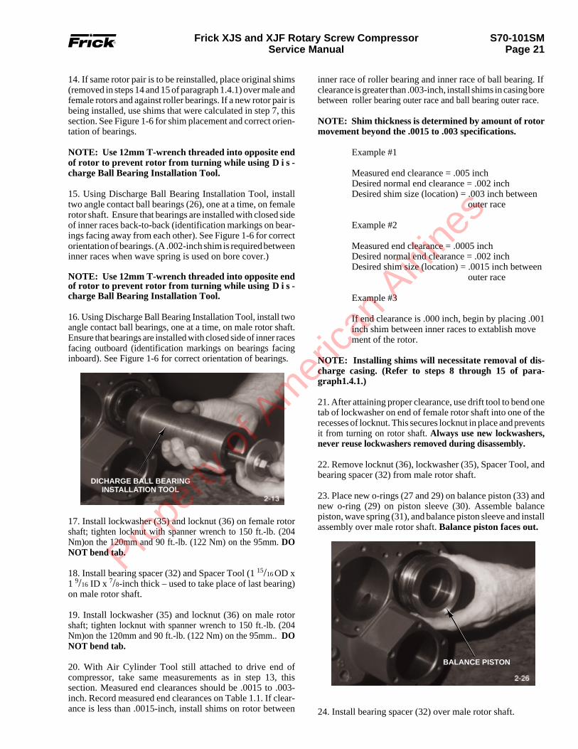
24. Install bearing spacer (32) over male rotor shaft.
inner race of roller bearing and inner race of ball bearing. Ifclearance is greater than .003-inch, install shims in casing borebetween roller bearing outer race and ball bearing outer race.
NOTE: Shim thickness is determined by amount of rotormovement beyond the .0015 to .003 specifications.
Example #1
Measured end clearance = .005 inchDesired normal end clearance = .002 inchDesired shim size (location) = .003 inch between
outer race
Example #2
Measured end clearance = .0005 inchDesired normal end clearance = .002 inchDesired shim size (location) = .0015 inch between
outer race
Example #3
If end clearance is .000 inch, begin by placing .001inch shim between inner races to extablish movement of the rotor.
NOTE: Installing shims will necessitate removal of dis-charge casing. (Refer to steps 8 through 15 of para-graph1.4.1.)
21. After attaining proper clearance, use drift tool to bend onetab of lockwasher on end of female rotor shaft into one of therecesses of locknut. This secures locknut in place and preventsit from turning on rotor shaft. Always use new lockwashers,never reuse lockwashers removed during disassembly.
22. Remove locknut (36), lockwasher (35), Spacer Tool, andbearing spacer (32) from male rotor shaft.
23. Place new o-rings (27 and 29) on balance piston (33) andnew o-ring (29) on piston sleeve (30). Assemble balancepiston, wave spring (31), and balance piston sleeve and installassembly over male rotor shaft. Balance piston faces out.
BALANCE PISTON
14. If same rotor pair is to be reinstalled, place original shims(removed in steps 14 and 15 of paragraph 1.4.1) over male andfemale rotors and against roller bearings. If a new rotor pair isbeing installed, use shims that were calculated in step 7, thissection. See Figure 1-6 for shim placement and correct orien-tation of bearings.
NOTE: Use 12mm T-wrench threaded into opposite endof rotor to prevent rotor from turning while using D i s -charge Ball Bearing Installation Tool.
15. Using Discharge Ball Bearing Installation Tool, installtwo angle contact ball bearings (26), one at a time, on femalerotor shaft. Ensure that bearings are installed with closed sideof inner races back-to-back (identification markings on bear-ings facing away from each other). See Figure 1-6 for correctorientation of bearings. (A .002-inch shim is required betweeninner races when wave spring is used on bore cover.)
NOTE: Use 12mm T-wrench threaded into opposite endof rotor to prevent rotor from turning while using D i s -charge Ball Bearing Installation Tool.
16. Using Discharge Ball Bearing Installation Tool, install twoangle contact ball bearings, one at a time, on male rotor shaft.Ensure that bearings are installed with closed side of inner racesfacing outboard (identification markings on bearings facinginboard). See Figure 1-6 for correct orientation of bearings.
DICHARGE BALL BEARINGINSTALLATION TOOL
17. Install lockwasher (35) and locknut (36) on female rotorshaft; tighten locknut with spanner wrench to 150 ft.-lb. (204Nm)on the 120mm and 90 ft.-lb. (122 Nm) on the 95mm. DONOT bend tab.
18. Install bearing spacer (32) and Spacer Tool (1 15/16 OD x1 9/16 ID x 7/8-inch thick – used to take place of last bearing)on male rotor shaft.
19. Install lockwasher (35) and locknut (36) on male rotorshaft; tighten locknut with spanner wrench to 150 ft.-lb. (204Nm)on the 120mm and 90 ft.-lb. (122 Nm) on the 95mm.. DONOT bend tab.
20. With Air Cylinder Tool still attached to drive end ofcompressor, take same measurements as in step 13, thissection. Measured end clearances should be .0015 to .003-inch. Record measured end clearances on Table 1.1. If clear-ance is less than .0015-inch, install shims on rotor between
Prope
rty o
f Am
erica
n Airli
nes

S70-101SMPage 22
Frick XJS and XJF Rotary Screw CompressorService Manual
32. Install modified Female Distance Sleeve Tool (femaledistance sleeve with center hole drilled out to 5/8-inch) overfemale rotor shaft and thread 5 1/2-inch guide pin into end ofshaft. Install modified Outlet Bore Cover Tool (part ofDischarge Ball Bearing Removal Tool) with wave spring(42) on discharge casing; secure with capscrews (8, Figure1-4). Tighten capscrews to a torque value of 18 foot-pounds(24.5 Nm).
33. With Air Cylinder Tool still attached to drive end ofcompressor and using regulator to restrict air pressure to 35psi max., take same measurements as in step 13, this section.With bearing clamped, record female rotor “measured” endplay in Table 1.1 for future reference.
34. Remove modified Female Distance Sleeve Tool, guidepin, and modified Outlet Bore Cover Tool from female rotor.
35. Install compression springs (37) in outlet bore cover(39). Install new o-ring (27) on cover. Install male distancesleeve (38), with spring pin hole at 12 o’clock position inoutlet bore cover; secure with capscrews (8, Figure 1-4).Tighten capscrews to a torque value of 18 foot-pounds (24.5Nm). Ensure that spring pin (9, Figure 1-4) in coverengages hole in male distance sleeve.
36. Install new o-ring (27) in outlet bore cover (41). Installfemale distance sleeve (44), with roll pin hole at 7 o’clockposition, wave spring (42), and outlet bore cover; securewith capscrews (8, Figure 1-4). Tighten capscrews to atorque value of 18 foot-pounds (24.5 Nm). Ensure thatspring pin (40) in cover engages hole in female distancesleeve.
37. Install slide valve and slide stop. (Refer to paragraph 1.3.2.)
38. Install jackshaft and gears. (Refer to paragraph 1.2.2.)
39. Install shaft seal. (Refer to paragraph 1.1.2.)
With bearing clamped, record male rotor “measured” endplay in Table 1.1 for future reference (should be within.0015" - .003".
31. Remove modified Male Distance Sleeve Tool, guide pin,and modified Outlet Bore Cover Tool from male rotor.
28. Install lockwasher (35) and locknut (36) on male rotorshaft; tighten locknut with spanner wrench. Bend one tab oflockwasher on end of male rotor shaft into one of the recessesof locknut. This secures locknut in place and prevents it fromturning on rotor shaft.
29. Install modified Male Distance Sleeve Tool (male dis-tance sleeve with center hole drilled out to 5/8-inch) over malerotor shaft and thread 3 1/2-inch guide pin into end of shaft.Install modified Outlet Bore Cover Tool (part of DischargeBall Bearing Removal Tool) with compression springs (37)on discharge casing; secure with capscrews (8, Figure 1-4).Tighten capscrews to a torque value of 18 foot-pounds (24.5Nm).
30. With Air Cylinder Tool still attached to drive end ofcompressor and using regulator to restrict air pressure to 35psi max., take same measurements as in step 13, this section.
COMPRESSORDISCHARGE END
OUTBOARD HALF(INNER RACE)
1.4.2 ROTORS AND BEARINGS – INSTALLATION. (CONTD)
outboard half of inner race of four-point contact ball bearingon male rotor shaft.
INBOARD HALF(INNER RACE)
DISCHARGEBALL BEARING
INSTALLATION TOOL
26. Install outer race of four-point contact ball bearing (34) onmale rotor shaft.
27. Using Discharge Ball Bearing Installation Tool, install
25. Using Discharge Ball Bearing Installation Tool, installinboard half of inner race of four-point contact ball bearing(34) on male rotor shaft.
OUTLET BORE COVERTOOL
CHECKING MALE ROTOR“MEASURED” END PLAY
Prope
rty o
f Am
erica
n Airli
nes

S70-101SMPage 23
Frick XJS and XJF Rotary Screw CompressorService Manual
F
M
1 2 2 3
1 2 2
WHEN SHIMS ARE REQUIRED, INSTALLBETWEEN OUTER RACES TO DECREASEDISCHARGE END CLEARANCE - INSTALLBETWEEN INNER RACES TO INCREASEDISCHARGE END CLEARANCE.
INSTALL BALL BEARINGSWITH IDENTIFICATIONMARK ON THIS SIDE ONLY.
INSTALL BALL BEARINGWITH IDENTIFICATIONMARK ON THIS SIDE ONLY.
INSTALL BALL BEARINGWITH IDENTIFICATIONMARK ON THIS SIDE ONLY.
BEARING INSTALLATIONMALE ROTOR
BEARING INSTALLATIONFEMALE ROTOR
LOCATION OF .002" SHIM
1. Roller Bearing2. Angular Contact Ball Bearing3. Four-Point Contact Ball Bearing
Figure 1-6. Bearing Orientation.
Prope
rty o
f Am
erica
n Airli
nes
S70-101SMPage 24
Frick XJS and XJF Rotary Screw CompressorService Manual
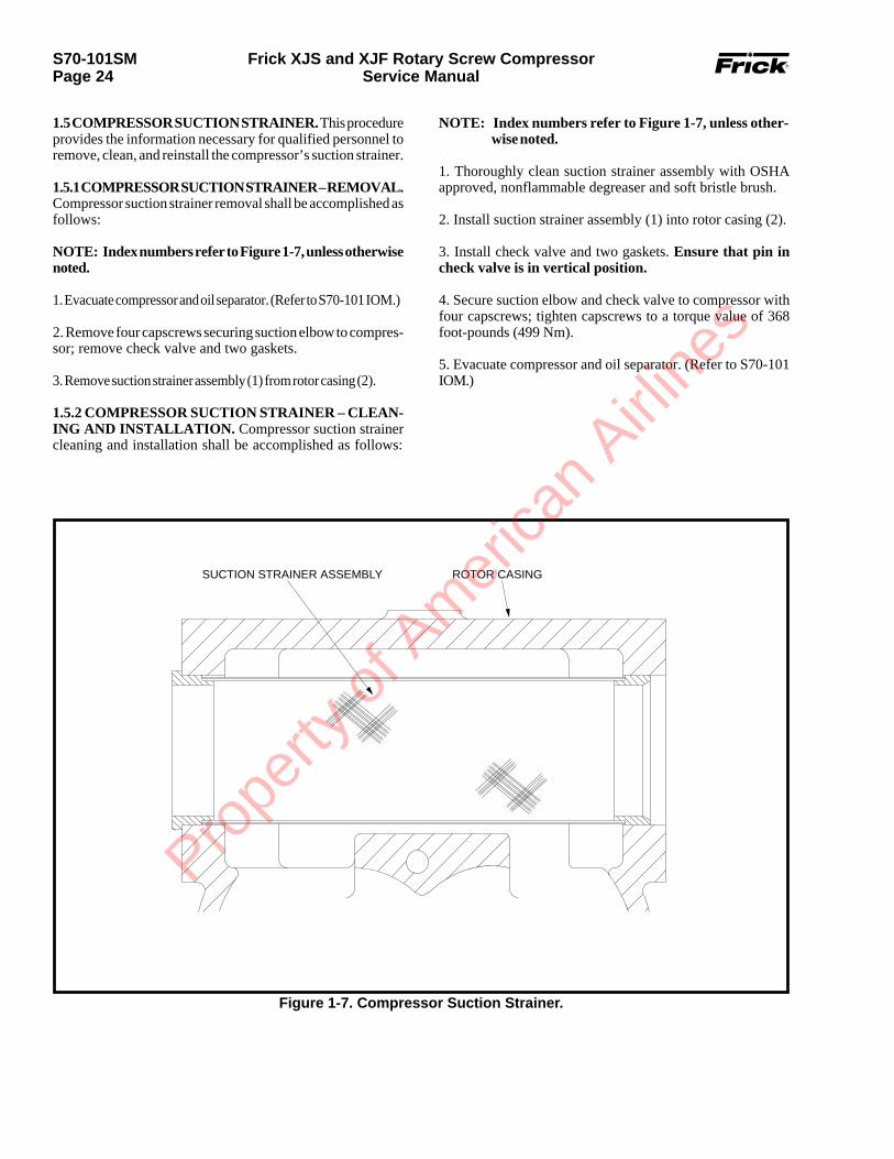
1.5 COMPRESSOR SUCTION STRAINER. This procedureprovides the information necessary for qualified personnel toremove, clean, and reinstall the compressor’s suction strainer.
1.5.1 COMPRESSOR SUCTION STRAINER – REMOVAL.Compressor suction strainer removal shall be accomplished asfollows:
NOTE: Index numbers refer to Figure 1-7, unless otherwisenoted.
1. Evacuate compressor and oil separator. (Refer to S70-101 IOM.)
2. Remove four capscrews securing suction elbow to compres-sor; remove check valve and two gaskets.
3. Remove suction strainer assembly (1) from rotor casing (2).
1.5.2 COMPRESSOR SUCTION STRAINER – CLEAN-ING AND INSTALLATION. Compressor suction strainercleaning and installation shall be accomplished as follows:
SUCTION STRAINER ASSEMBLY ROTOR CASING
Figure 1-7. Compressor Suction Strainer.
NOTE: Index numbers refer to Figure 1-7, unless other-wise noted.
1. Thoroughly clean suction strainer assembly with OSHAapproved, nonflammable degreaser and soft bristle brush.
2. Install suction strainer assembly (1) into rotor casing (2).
3. Install check valve and two gaskets. Ensure that pin incheck valve is in vertical position.
4. Secure suction elbow and check valve to compressor withfour capscrews; tighten capscrews to a torque value of 368foot-pounds (499 Nm).
5. Evacuate compressor and oil separator. (Refer to S70-101IOM.)
Prope
rty o
f Am
erica
n Airli
nes

S70-101SMPage 25
Frick XJS and XJF Rotary Screw CompressorService Manual
Figure 1-8. Orifice Hole Location for XJS and XJF 95.
DISCHARGE BEARINGORIFICE
MAIN OIL INJECTIONORIFICE
The orifice holes shown require cleaning to ensure proper oil flow.
See Figure 1-9 for location of oil feed orifice hole.
Prope
rty o
f Am
erica
n Airli
nes

S70-101SMPage 26
Frick XJS and XJF Rotary Screw CompressorService Manual
Figure 1-9. Orifice Hole Location for XJS and XJF 120.
DISCHARGE BEARING ORIFICE ONCOMPRESSOR WITH CONTROL VALVEMOUNTED ON DISCHARGE HOUSING
ROTORSCL
MAIN OIL SUPPLY
LOCATION OF MAIN OIL INJECTIONORIFICE PLUG
CL MOUNTING HOLE
HIGH VILIQUID INJECTION
ECONOMIZER
1
23
2
4
1. Seal Housing2. Elbow3. Oil Supply Line4. Gear Cover
Discharge bearing orifice oncompressors which do not havecontrol valve mounted ondischarge housing.
Orifice hole to spray gear
Oil feedorifice hole
The orifice holes shown require cleaning to ensure proper oil flow.
(Typ. - 95mmand 120mm) Pro
perty
of A
mer
ican
Airline
s
S70-101SMPage 27
Frick XJS and XJF Rotary Screw CompressorService Manual
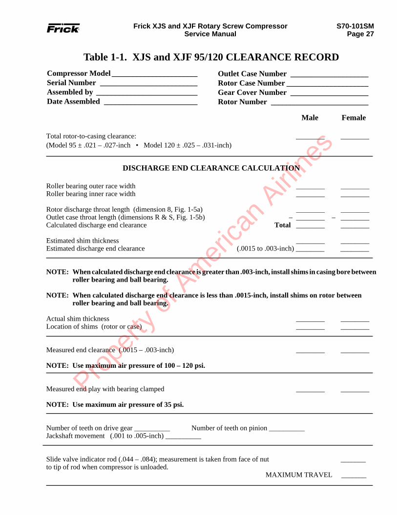
Table 1-1. XJS and XJF 95/120 CLEARANCE RECORD
Male Female
Total rotor-to-casing clearance: ________ ________(Model 95 ± .021 – .027-inch • Model 120 ± .025 – .031-inch)
Compressor Model ______________________Serial Number _________________________Assembled by __________________________Date Assembled ________________________
Outlet Case Number ____________________Rotor Case Number _____________________Gear Cover Number ____________________Rotor Number _________________________
DISCHARGE END CLEARANCE CALCULATION
Roller bearing outer race width ________ ________Roller bearing inner race width ________ ________
Rotor discharge throat length (dimension 8, Fig. 1-5a) ________ ________Outlet case throat length (dimensions R & S, Fig. 1-5b) – ________ – ________Calculated discharge end clearance Total ________ ________
Estimated shim thickness ________ ________Estimated discharge end clearance (.0015 to .003-inch) ________ ________
NOTE: When calculated discharge end clearance is greater than .003-inch, install shims in casing bore betweenroller bearing and ball bearing.
NOTE: When calculated discharge end clearance is less than .0015-inch, install shims on rotor betweenroller bearing and ball bearing.
Actual shim thickness ________ ________Location of shims (rotor or case) ________ ________
Measured end clearance (.0015 – .003-inch) ________ ________
NOTE: Use maximum air pressure of 100 – 120 psi.
Measured end play with bearing clamped ________ ________
NOTE: Use maximum air pressure of 35 psi.
Number of teeth on drive gear __________ Number of teeth on pinion __________Jackshaft movement (.001 to .005-inch) __________
Slide valve indicator rod (.044 – .084); measurement is taken from face of nut _______to tip of rod when compressor is unloaded.
MAXIMUM TRAVEL _______
Prope
rty o
f Am
erica
n Airli
nes

Printed in U.S.A. Subject to Change Without Notice
100 CV Avenue, P.O. Box 997 Waynesboro, Pennsylvania USA 17268-0997Phone: 717-762-2121 • Fax: 717-762-8624 • www.frickcold.com
Prope
rty o
f Am
erica
n Airli
nes