rotex hpsu bi-bloc ultra · 2020-03-06 · rotex hpsu bi-bloc ultra english + installer reference...
TRANSCRIPT
Installer reference guideROTEX HPSU Bi-Bloc Ultra English
+
Installer reference guide
ROTEX HPSU Bi-Bloc Ultra
RRGA04DAV3RRGA06DAV3RRGA08DAV3
RHBX04DA6VRHBX04DA9WRHBX08DA6VRHBX08DA9W

Table of contents
Installer reference guide
2RRGA04~08DAV3 + RHBX04+08DA
ROTEX HPSU Bi-Bloc Ultra4P495262-1B – 2019.10
Table of contents
1 General safety precautions 31.1 About the documentation .......................................................... 3
1.1.1 Meaning of warnings and symbols.............................. 31.2 For the installer.......................................................................... 4
1.2.1 General ....................................................................... 41.2.2 Installation site ............................................................ 41.2.3 Refrigerant .................................................................. 41.2.4 Brine............................................................................ 51.2.5 Water .......................................................................... 51.2.6 Electrical ..................................................................... 6
2 About the documentation 62.1 About this document.................................................................. 62.2 Installer reference guide at a glance ......................................... 7
3 About the box 73.1 Overview: About the box ........................................................... 73.2 Outdoor unit............................................................................... 7
3.2.1 To unpack the outdoor unit ......................................... 73.2.2 To handle the outdoor unit .......................................... 73.2.3 To remove the accessories from the outdoor unit....... 8
3.3 Indoor unit ................................................................................. 83.3.1 To unpack the indoor unit ........................................... 83.3.2 To remove the accessories from the indoor unit......... 8
4 About the units and options 84.1 Overview: About the units and options...................................... 84.2 Identification .............................................................................. 8
4.2.1 Identification label: Outdoor unit ................................. 84.2.2 Identification label: Indoor unit .................................... 9
4.3 Combining units and options ..................................................... 94.3.1 Possible options for the outdoor unit........................... 94.3.2 Possible options for the indoor unit............................. 94.3.3 Possible combinations of indoor unit and outdoor
unit .............................................................................. 104.3.4 Possible combinations of indoor unit and domestic
hot water tank ............................................................. 10
5 Application guidelines 105.1 Overview: Application guidelines............................................... 105.2 Setting up the space heating/cooling system ............................ 10
5.2.1 Single room................................................................. 105.2.2 Multiple rooms – One LWT zone ................................ 125.2.3 Multiple rooms – Two LWT zones............................... 14
5.3 Setting up an auxiliary heat source for space heating............... 155.4 Setting up the domestic hot water tank ..................................... 16
5.4.1 System layout – Standalone DHW tank...................... 165.4.2 Selecting the volume and desired temperature for
the DHW tank.............................................................. 165.4.3 Setup and configuration – DHW tank.......................... 175.4.4 DHW pump for instant hot water................................. 175.4.5 DHW pump for disinfection ......................................... 175.4.6 DHW pump for tank preheating .................................. 18
5.5 Setting up the energy metering ................................................. 185.5.1 Produced heat............................................................. 185.5.2 Consumed energy....................................................... 185.5.3 Normal kWh rate power supply................................... 185.5.4 Preferential kWh rate power supply ............................ 19
5.6 Setting up the power consumption control ................................ 195.6.1 Permanent power limitation ........................................ 195.6.2 Power limitation activated by digital inputs ................. 205.6.3 Power limitation process ............................................. 20
5.7 Setting up an external temperature sensor ............................... 21
6 Preparation 216.1 Overview: Preparation............................................................... 216.2 Preparing the installation site .................................................... 21
6.2.1 Installation site requirements of the outdoor unit ......... 216.2.2 Additional installation site requirements of the
outdoor unit in cold climates ........................................ 226.2.3 Installation site requirements of the indoor unit ........... 23
6.3 Preparing refrigerant piping........................................................ 256.3.1 Refrigerant piping requirements................................... 256.3.2 Refrigerant piping insulation ........................................ 25
6.4 Preparing water piping ............................................................... 256.4.1 Water circuit requirements ........................................... 256.4.2 Formula to calculate the expansion vessel pre-
pressure ....................................................................... 266.4.3 To check the water volume and flow rate .................... 266.4.4 Changing the pre-pressure of the expansion vessel.... 276.4.5 To check the water volume: Examples ........................ 28
6.5 Preparing electrical wiring .......................................................... 286.5.1 About preparing electrical wiring.................................. 286.5.2 About preferential kWh rate power supply ................... 286.5.3 Overview of electrical connections except external
actuators ...................................................................... 296.5.4 Overview of electrical connections for external and
internal actuators ......................................................... 29
7 Installation 297.1 Overview: Installation ................................................................. 297.2 Opening the units ....................................................................... 30
7.2.1 About opening the units ............................................... 307.2.2 To open the outdoor unit.............................................. 307.2.3 To open the indoor unit ................................................ 30
7.3 Mounting the outdoor unit........................................................... 317.3.1 About mounting the outdoor unit.................................. 317.3.2 Precautions when mounting the outdoor unit............... 317.3.3 To provide the installation structure ............................. 317.3.4 To install the outdoor unit............................................. 327.3.5 To provide drainage ..................................................... 337.3.6 To prevent the outdoor unit from falling over ............... 34
7.4 Mounting the indoor unit ............................................................. 347.4.1 About mounting the indoor unit .................................... 347.4.2 Precautions when mounting the indoor unit................. 347.4.3 To install the indoor unit ............................................... 347.4.4 To connect the drain hose to the drain ........................ 35
7.5 Connecting the refrigerant piping ............................................... 357.5.1 About connecting the refrigerant piping ....................... 357.5.2 Precautions when connecting the refrigerant piping .... 357.5.3 Guidelines when connecting the refrigerant piping ...... 367.5.4 Pipe bending guidelines............................................... 367.5.5 To flare the pipe end .................................................... 367.5.6 To braze the pipe end .................................................. 367.5.7 Using the stop valve and service port .......................... 377.5.8 To connect the refrigerant piping to the outdoor unit ... 377.5.9 To connect the refrigerant piping to the indoor unit ..... 37
7.6 Checking the refrigerant piping .................................................. 387.6.1 About checking the refrigerant piping .......................... 387.6.2 Precautions when checking the refrigerant piping ....... 387.6.3 To check for leaks........................................................ 387.6.4 To perform vacuum drying ........................................... 38
7.7 Charging refrigerant ................................................................... 397.7.1 About charging refrigerant ........................................... 397.7.2 Precautions when charging refrigerant ........................ 397.7.3 To determine the additional refrigerant amount ........... 397.7.4 To determine the complete recharge amount .............. 397.7.5 To charge additional refrigerant ................................... 397.7.6 To fix the fluorinated greenhouse gases label ............. 40
7.8 Connecting water piping............................................................. 407.8.1 About connecting the water piping............................... 407.8.2 Precautions when connecting the water piping............ 407.8.3 To connect the water piping......................................... 407.8.4 To fill the water circuit .................................................. 417.8.5 To fill the domestic hot water tank ............................... 417.8.6 To insulate the water piping ......................................... 41
7.9 Connecting the electrical wiring.................................................. 41

1 General safety precautions
Installer reference guide
3RRGA04~08DAV3 + RHBX04+08DAROTEX HPSU Bi-Bloc Ultra4P495262-1B – 2019.10
7.9.1 About connecting the electrical wiring......................... 417.9.2 About electrical compliance ........................................ 417.9.3 Precautions when connecting the electrical wiring ..... 417.9.4 Guidelines when connecting the electrical wiring ....... 417.9.5 Specifications of standard wiring components............ 427.9.6 To connect the electrical wiring on the outdoor unit.... 427.9.7 To connect the electrical wiring on the indoor unit...... 437.9.8 To connect the main power supply ............................. 437.9.9 To connect the backup heater power supply .............. 447.9.10 To connect the shut-off valve...................................... 457.9.11 To connect the electricity meters ................................ 457.9.12 To connect the domestic hot water pump ................... 457.9.13 To connect the alarm output ....................................... 467.9.14 To connect the space cooling/heating ON/OFF
output .......................................................................... 467.9.15 To connect the changeover to external heat source... 467.9.16 To connect the power consumption digital inputs ....... 467.9.17 To connect the safety thermostat (normally closed
contact) ....................................................................... 477.10 Finishing the outdoor unit installation ........................................ 47
7.10.1 To finish the outdoor unit installation .......................... 477.11 Finishing the indoor unit installation .......................................... 47
7.11.1 To close the indoor unit............................................... 47
8 Configuration 478.1 Overview: Configuration ............................................................ 47
8.1.1 To access the most used commands ......................... 488.2 Configuration wizard.................................................................. 488.3 Possible screens ....................................................................... 49
8.3.1 Possible screens: Overview........................................ 498.3.2 Home screen............................................................... 498.3.3 Main menu screen ...................................................... 508.3.4 Menu screen ............................................................... 508.3.5 Setpoint screen ........................................................... 518.3.6 Detailed screen with values ........................................ 518.3.7 Detailed screen with weather-dependent curve.......... 518.3.8 Schedule screen: Example ......................................... 52
8.4 Settings menu ........................................................................... 538.4.1 Malfunctioning............................................................. 538.4.2 Room .......................................................................... 538.4.3 Main zone ................................................................... 558.4.4 Additional zone ........................................................... 598.4.5 Space heating/cooling................................................. 618.4.6 Tank ............................................................................ 658.4.7 User settings ............................................................... 678.4.8 Information .................................................................. 698.4.9 Installer settings .......................................................... 69
8.5 Menu structure: Overview user settings .................................... 788.6 Menu structure: Overview installer settings............................... 79
9 Commissioning 809.1 Overview: Commissioning......................................................... 809.2 Precautions when commissioning ............................................. 809.3 Checklist before commissioning................................................ 809.4 Checklist during commissioning ................................................ 80
9.4.1 To check the minimum flow rate ................................. 819.4.2 Air purge function........................................................ 819.4.3 To perform an operation test run ................................ 819.4.4 To perform an actuator test run .................................. 829.4.5 Underfloor heating screed dryout................................ 82
10 Hand-over to the user 8311 Maintenance and service 83
11.1 Overview: Maintenance and service ......................................... 8311.2 Maintenance safety precautions................................................ 8411.3 Checklist for yearly maintenance of the outdoor unit ................ 8411.4 Checklist for yearly maintenance of the indoor unit................... 8411.5 About cleaning the water filter in case of trouble....................... 85
11.5.1 To remove the water filter ........................................... 8511.5.2 To clean the water filter in case of trouble .................. 85
11.5.3 To install the water filter ............................................... 86
12 Troubleshooting 8612.1 Overview: Troubleshooting......................................................... 8612.2 Precautions when troubleshooting ............................................. 8612.3 Solving problems based on symptoms....................................... 86
12.3.1 Symptom: The unit is NOT heating or cooling asexpected ...................................................................... 86
12.3.2 Symptom: The compressor does NOT start (spaceheating or domestic water heating).............................. 87
12.3.3 Symptom: The system is making gurgling noisesafter commissioning ..................................................... 87
12.3.4 Symptom: The pump is making noise (cavitation) ....... 8712.3.5 Symptom: The pressure relief valve opens.................. 8712.3.6 Symptom: The water pressure relief valve leaks ......... 8812.3.7 Symptom: The space is NOT sufficiently heated at
low outdoor temperatures ............................................ 8812.3.8 Symptom: The pressure at the tapping point is
temporarily unusually high ........................................... 8812.3.9 Symptom: Decoration panels are pushed away due
to a swollen tank .......................................................... 8812.3.10 Symptom: Tank disinfection function is NOT
completed correctly (AH-error)..................................... 8812.4 Solving problems based on error codes..................................... 89
12.4.1 To display the help text in case of a malfunction ......... 8912.4.2 Error codes: Overview ................................................. 89
13 Disposal 9013.1 Overview: Disposal..................................................................... 9013.2 To pump down............................................................................ 9113.3 To start and stop forced cooling ................................................. 91
14 Technical data 9214.1 Piping diagram: Outdoor unit...................................................... 9214.2 Piping diagram: Indoor unit ........................................................ 9314.3 Wiring diagram: Outdoor unit ..................................................... 9414.4 Wiring diagram: Indoor unit ........................................................ 9514.5 Table 1 – Maximum refrigerant charge allowed in a room:
indoor unit................................................................................... 9814.6 Table 2 – Minimum floor area: indoor unit .................................. 9814.7 Table 3 – Minimum venting opening area for natural
ventilation: indoor unit ................................................................ 9914.8 ESP curve: Indoor unit ...............................................................100
15 Glossary 10016 Field settings table 101
1 General safety precautions
1.1 About the documentation▪ The original documentation is written in English. All other
languages are translations.
▪ The precautions described in this document cover very importanttopics, follow them carefully.
▪ The installation of the system, and all activities described in theinstallation manual and in the installer reference guide MUST beperformed by an authorised installer.
1.1.1 Meaning of warnings and symbols
DANGERIndicates a situation that results in death or serious injury.
DANGER: RISK OF ELECTROCUTIONIndicates a situation that could result in electrocution.
1 General safety precautions
Installer reference guide
4RRGA04~08DAV3 + RHBX04+08DA
ROTEX HPSU Bi-Bloc Ultra4P495262-1B – 2019.10
DANGER: RISK OF BURNINGIndicates a situation that could result in burning because ofextreme hot or cold temperatures.
DANGER: RISK OF EXPLOSIONIndicates a situation that could result in explosion.
WARNINGIndicates a situation that could result in death or seriousinjury.
WARNING: FLAMMABLE MATERIAL
CAUTIONIndicates a situation that could result in minor or moderateinjury.
NOTICEIndicates a situation that could result in equipment orproperty damage.
INFORMATIONIndicates useful tips or additional information.
Symbol ExplanationBefore installation, read the installation andoperation manual, and the wiring instruction sheet.
Before performing maintenance and service tasks,read the service manual.For more information, see the installer and userreference guide.
1.2 For the installer
1.2.1 GeneralIf you are NOT sure how to install or operate the unit, contact yourdealer.
NOTICEImproper installation or attachment of equipment oraccessories could result in electric shock, short-circuit,leaks, fire or other damage to the equipment. Only useaccessories, optional equipment and spare parts made orapproved by ROTEX.
WARNINGMake sure installation, testing and applied materialscomply with applicable legislation (on top of theinstructions described in the ROTEX documentation).
CAUTIONWear adequate personal protective equipment (protectivegloves, safety glasses,…) when installing, maintaining orservicing the system.
WARNINGTear apart and throw away plastic packaging bags so thatnobody, especially children, can play with them. Possiblerisk: suffocation.
DANGER: RISK OF BURNING▪ Do NOT touch the refrigerant piping, water piping or
internal parts during and immediately after operation. Itcould be too hot or too cold. Give it time to return tonormal temperature. If you must touch it, wearprotective gloves.
▪ Do NOT touch any accidental leaking refrigerant.
WARNINGProvide adequate measures to prevent that the unit can beused as a shelter by small animals. Small animals thatmake contact with electrical parts can cause malfunctions,smoke or fire.
CAUTIONDo NOT touch the air inlet or aluminium fins of the unit.
NOTICE▪ Do NOT place any objects or equipment on top of the
unit.
▪ Do NOT sit, climb or stand on the unit.
NOTICEWorks executed on the outdoor unit are best done underdry weather conditions to avoid water ingress.
In accordance with the applicable legislation, it might be necessaryto provide a logbook with the product containing at least: informationon maintenance, repair work, results of tests, stand-by periods,…
Also, at least, following information MUST be provided at anaccessible place at the product:
▪ Instructions for shutting down the system in case of an emergency
▪ Name and address of fire department, police and hospital
▪ Name, address and day and night telephone numbers forobtaining service
In Europe, EN378 provides the necessary guidance for this logbook.
1.2.2 Installation site▪ Provide sufficient space around the unit for servicing and air
circulation.
▪ Make sure the installation site withstands the weight and vibrationof the unit.
▪ Make sure the area is well ventilated. Do NOT block anyventilation openings.
▪ Make sure the unit is level.
Do NOT install the unit in the following places:
▪ In potentially explosive atmospheres.
▪ In places where there is machinery that emits electromagneticwaves. Electromagnetic waves may disturb the control system,and cause malfunction of the equipment.
▪ In places where there is a risk of fire due to the leakage offlammable gases (example: thinner or gasoline), carbon fibre,ignitable dust.
▪ In places where corrosive gas (example: sulphurous acid gas) isproduced. Corrosion of copper pipes or soldered parts may causethe refrigerant to leak.
1.2.3 RefrigerantIf applicable. See the installation manual or installer reference guideof your application for more information.

1 General safety precautions
Installer reference guide
5RRGA04~08DAV3 + RHBX04+08DAROTEX HPSU Bi-Bloc Ultra4P495262-1B – 2019.10
NOTICEMake sure refrigerant piping installation complies withapplicable legislation. In Europe, EN378 is the applicablestandard.
NOTICEMake sure the field piping and connections are NOTsubjected to stress.
WARNINGDuring tests, NEVER pressurize the product with apressure higher than the maximum allowable pressure (asindicated on the nameplate of the unit).
WARNINGTake sufficient precautions in case of refrigerant leakage. Ifrefrigerant gas leaks, ventilate the area immediately.Possible risks:
▪ Excessive refrigerant concentrations in a closed roomcan lead to oxygen deficiency.
▪ Toxic gas may be produced if refrigerant gas comesinto contact with fire.
DANGER: RISK OF EXPLOSIONPump down – Refrigerant leakage. If you want to pumpdown the system, and there is a leak in the refrigerantcircuit:
▪ Do NOT use the unit's automatic pump down function,with which you can collect all refrigerant from thesystem into the outdoor unit. Possible consequence:Self-combustion and explosion of the compressorbecause of air going into the operating compressor.
▪ Use a separate recovery system so that the unit'scompressor does NOT have to operate.
WARNINGALWAYS recover the refrigerant. Do NOT release themdirectly into the environment. Use a vacuum pump toevacuate the installation.
NOTICEAfter all the piping has been connected, make sure there isno gas leak. Use nitrogen to perform a gas leak detection.
NOTICE▪ To avoid compressor breakdown, do NOT charge more
than the specified amount of refrigerant.
▪ When the refrigerant system is to be opened,refrigerant MUST be treated according to the applicablelegislation.
WARNINGMake sure there is no oxygen in the system. Refrigerantmay only be charged after performing the leak test and thevacuum drying.
▪ In case recharge is required, see the nameplate of the unit. Itstates the type of refrigerant and necessary amount.
▪ The unit is factory charged with refrigerant and depending on pipesizes and pipe lengths some systems require additional chargingof refrigerant.
▪ Only use tools exclusively for the refrigerant type used in thesystem, this to ensure pressure resistance and prevent foreignmaterials from entering into the system.
▪ Charge the liquid refrigerant as follows:
If ThenA siphon tube is present
(i.e., the cylinder is marked with"Liquid filling siphon attached")
Charge with the cylinder upright.
A siphon tube is NOT present Charge with the cylinder upsidedown.
▪ Open refrigerant cylinders slowly.
▪ Charge the refrigerant in liquid form. Adding it in gas form mayprevent normal operation.
CAUTIONWhen the refrigerant charging procedure is done or whenpausing, close the valve of the refrigerant tankimmediately. If the valve is NOT closed immediately,remaining pressure might charge additional refrigerant.Possible consequence: Incorrect refrigerant amount.
1.2.4 BrineIf applicable. See the installation manual or installer reference guideof your application for more information.
WARNINGThe selection of the brine MUST be in accordance with theapplicable legislation.
WARNINGTake sufficient precautions in case of brine leakage. Ifbrine leaks, ventilate the area immediately and contactyour local dealer.
WARNINGThe ambient temperature inside the unit can get muchhigher than that of the room, e.g. 70°C. In case of a brineleak, hot parts inside the unit can create a hazardoussituation.
WARNINGThe use and installation of the application MUST complywith the safety and environmental precautions specified inthe applicable legislation.
1.2.5 WaterIf applicable. See the installation manual or installer reference guideof your application for more information.
NOTICEMake sure water quality complies with EU directive98/83 EC.
2 About the documentation
Installer reference guide
6RRGA04~08DAV3 + RHBX04+08DA
ROTEX HPSU Bi-Bloc Ultra4P495262-1B – 2019.10
1.2.6 Electrical
DANGER: RISK OF ELECTROCUTION▪ Turn OFF all power supply before removing the
switch box cover, connecting electrical wiring ortouching electrical parts.
▪ Disconnect the power supply for more than 1 minute,and measure the voltage at the terminals of main circuitcapacitors or electrical components before servicing.The voltage MUST be less than 50 V DC before youcan touch electrical components. For the location of theterminals, see the wiring diagram.
▪ Do NOT touch electrical components with wet hands.
▪ Do NOT leave the unit unattended when the servicecover is removed.
WARNINGIf NOT factory installed, a main switch or other means fordisconnection, having a contact separation in all polesproviding full disconnection under overvoltage category IIIcondition, MUST be installed in the fixed wiring.
WARNING▪ ONLY use copper wires.
▪ Make sure the field wiring complies with the applicablelegislation.
▪ All field wiring MUST be performed in accordance withthe wiring diagram supplied with the product.
▪ NEVER squeeze bundled cables and make sure theydo NOT come in contact with the piping and sharpedges. Make sure no external pressure is applied to theterminal connections.
▪ Make sure to install earth wiring. Do NOT earth the unitto a utility pipe, surge absorber, or telephone earth.Incomplete earth may cause electrical shock.
▪ Make sure to use a dedicated power circuit. NEVERuse a power supply shared by another appliance.
▪ Make sure to install the required fuses or circuitbreakers.
▪ Make sure to install an earth leakage protector. Failureto do so may cause electric shock or fire.
▪ When installing the earth leakage protector, make sureit is compatible with the inverter (resistant to highfrequency electric noise) to avoid unnecessary openingof the earth leakage protector.
CAUTIONWhen connecting the power supply, the earth connectionmust be made before the current-carrying connections areestablished. When disconnecting the power supply, thecurrent-carrying connections must be separated before theearth connection is. The length of the conductors betweenthe power supply stress relief and the terminal block itselfmust be as such that the current-carrying wires aretautened before the earth wire is in case the power supplyis pulled loose from the stress relief.
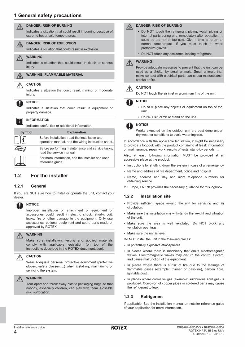
NOTICEPrecautions when laying power wiring:
▪ Do NOT connect wiring of different thicknesses to thepower terminal block (slack in the power wiring maycause abnormal heat).
▪ When connecting wiring which is the same thickness,do as shown in the figure above.
▪ For wiring, use the designated power wire and connectfirmly, then secure to prevent outside pressure beingexerted on the terminal board.
▪ Use an appropriate screwdriver for tightening theterminal screws. A screwdriver with a small head willdamage the head and make proper tighteningimpossible.
▪ Over-tightening the terminal screws may break them.
Install power cables at least 1 m away from televisions or radios toprevent interference. Depending on the radio waves, a distance of1 m may not be sufficient.
WARNING▪ After finishing the electrical work, confirm that each
electrical component and terminal inside the electricalcomponents box is connected securely.
▪ Make sure all covers are closed before starting up theunit.
NOTICEOnly applicable if the power supply is three‑phase, and thecompressor has an ON/OFF starting method.
If there exists the possibility of reversed phase after amomentary black out and the power goes on and off whilethe product is operating, attach a reversed phaseprotection circuit locally. Running the product in reversedphase can break the compressor and other parts.
2 About the documentation
2.1 About this documentTarget audienceAuthorised installers
Documentation setThis document is part of a documentation set. The complete setconsists of:
▪ General safety precautions:▪ Safety instructions that you must read before installing
▪ Format: Paper (in the box of the indoor unit)
▪ Indoor unit installation manual:▪ Installation instructions
▪ Format: Paper (in the box of the indoor unit)
▪ Outdoor unit installation manual:▪ Installation instructions
▪ Format: Paper (in the box of the outdoor unit)
3 About the box
Installer reference guide
7RRGA04~08DAV3 + RHBX04+08DAROTEX HPSU Bi-Bloc Ultra4P495262-1B – 2019.10
▪ Installer reference guide:▪ Preparation of the installation, good practices, reference data,…
▪ Format: Digital files on the ROTEX homepage
▪ Addendum book for optional equipment:▪ Additional info about how to install optional equipment
▪ Format: Paper (in the box of the indoor unit) + Digital files onthe ROTEX homepage
Latest revisions of the supplied documentation may be available onthe regional ROTEX website or via your dealer.
The original documentation is written in English. All other languagesare translations.
2.2 Installer reference guide at aglance
Chapter DescriptionGeneral safetyprecautions
Safety instructions that you must readbefore installing
About the documentation What documentation exists for theinstaller
About the box How to unpack the units and removetheir accessories
About the units andoptions
▪ How to identify the units
▪ Possible combinations of units andoptions
Application guidelines Various installation setups of the systemPreparation What to do and know before going
on‑siteInstallation What to do and know to install the
systemConfiguration What to do and know to configure the
system after it is installedCommissioning What to do and know to commission the
system after it is configuredHand‑over to the user What to give and explain to the userMaintenance and service How to maintain and service the unitsTroubleshooting What to do in case of problemsDisposal How to dispose of the systemTechnical data Specifications of the systemGlossary Definition of termsField settings table Table to be filled in by the installer, and
kept for future reference
Note: There is also an installer settingstable in the user reference guide. Thistable has to be filled in by the installerand handed over to the user.
3 About the box
3.1 Overview: About the boxThis chapter describes what you have to do after the boxes with theoutdoor and indoor unit are delivered on-site.
Keep the following in mind:
▪ At delivery, the unit MUST be checked for damage. Any damageMUST be reported immediately to the claims agent of the carrier.
▪ Bring the packed unit as close as possible to its final installationposition to prevent damage during transport.
▪ Prepare the path along which you want to bring the unit inside inadvance.
3.2 Outdoor unit
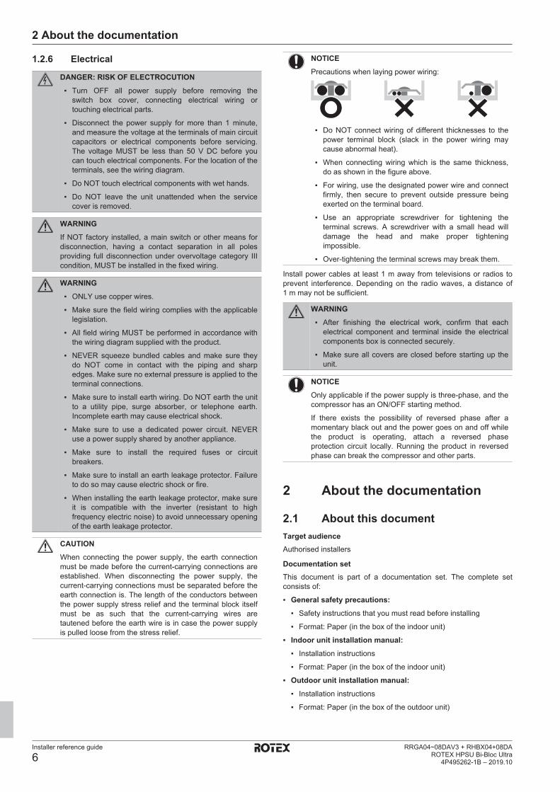
3.2.1 To unpack the outdoor unit
1 2
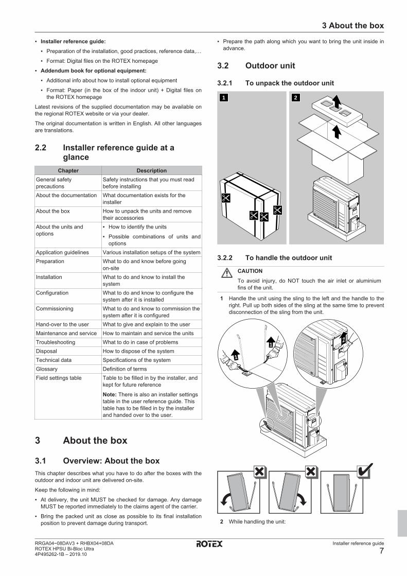
3.2.2 To handle the outdoor unit
CAUTIONTo avoid injury, do NOT touch the air inlet or aluminiumfins of the unit.
1 Handle the unit using the sling to the left and the handle to theright. Pull up both sides of the sling at the same time to preventdisconnection of the sling from the unit.
21
1
2 While handling the unit:

4 About the units and options
Installer reference guide
8RRGA04~08DAV3 + RHBX04+08DA
ROTEX HPSU Bi-Bloc Ultra4P495262-1B – 2019.10
▪ Keep both sides of the sling level.▪ Keep your back straight.
3 After mounting the unit, remove the sling from the unit by pulling1 side of the sling.
3.2.3 To remove the accessories from theoutdoor unit
1 Lift the outdoor unit. See "3.2.2 To handle the outdoor unit" [4 7].
2 Remove the accessories at the bottom of the package.
ENERG IJAY
IAIEENERG IJAY
IAIE
1×1× 1× 1× 2× 1×da b c e f
a Outdoor unit installation manualb Fluorinated greenhouse gases labelc Multilingual fluorinated greenhouse gases labeld Energy labele Unit mounting platef Bolts, nuts, washers, spring washers and wire clamp
3.3 Indoor unit
3.3.1 To unpack the indoor unit
1 2
3.3.2 To remove the accessories from theindoor unit
Some accessories are located inside the unit. To open the unit, see"7.2.3 To open the indoor unit" [4 30].
1× 1× 1× 1×a b c d
2×4× 1×fe g
1×h
a General safety precautionsb Addendum book for optional equipmentc Indoor unit installation manuald Operation manuale Sealing ring for shut-off valvef Shut-off valveg Overpressure bypass valveh Wall bracket
4 About the units and options
4.1 Overview: About the units andoptions
This chapter contains information about:
▪ Identifying the outdoor unit
▪ Identifying the indoor unit
▪ Combining the outdoor unit with options
▪ Combining the indoor unit with options
4.2 IdentificationNOTICEWhen installing or servicing several units at the same time,make sure NOT to switch the service panels betweendifferent models.
4.2.1 Identification label: Outdoor unitLocation
Model identificationExample: RR G A 06 DA V3
Code ExplanationRR Split outdoor pair heat pump
4 About the units and options
Installer reference guide
9RRGA04~08DAV3 + RHBX04+08DAROTEX HPSU Bi-Bloc Ultra4P495262-1B – 2019.10
Code ExplanationG Medium water temperature – ambient zone: −10~
−20°CA Refrigerant R3206 Capacity classDA Model seriesV3 Power supply
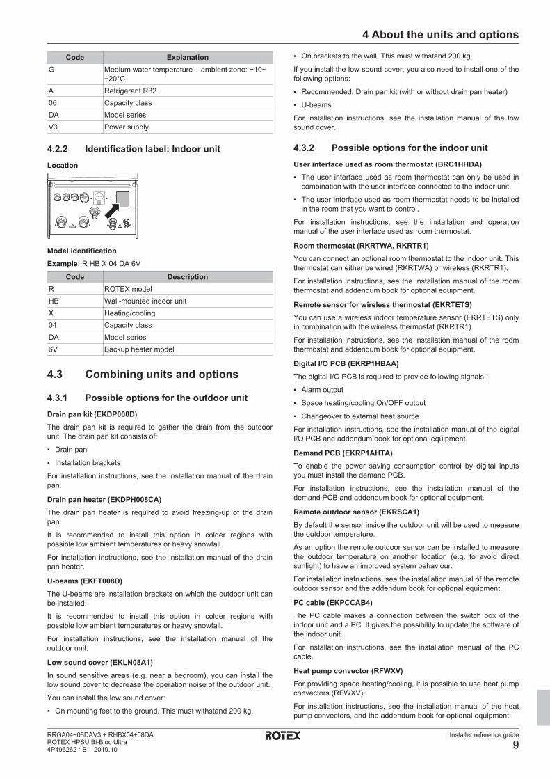
4.2.2 Identification label: Indoor unitLocation
Model identificationExample: R HB X 04 DA 6V
Code DescriptionR ROTEX modelHB Wall-mounted indoor unitX Heating/cooling04 Capacity classDA Model series6V Backup heater model
4.3 Combining units and options
4.3.1 Possible options for the outdoor unitDrain pan kit (EKDP008D)The drain pan kit is required to gather the drain from the outdoorunit. The drain pan kit consists of:
▪ Drain pan
▪ Installation brackets
For installation instructions, see the installation manual of the drainpan.
Drain pan heater (EKDPH008CA)The drain pan heater is required to avoid freezing-up of the drainpan.
It is recommended to install this option in colder regions withpossible low ambient temperatures or heavy snowfall.
For installation instructions, see the installation manual of the drainpan heater.
U-beams (EKFT008D)The U-beams are installation brackets on which the outdoor unit canbe installed.
It is recommended to install this option in colder regions withpossible low ambient temperatures or heavy snowfall.
For installation instructions, see the installation manual of theoutdoor unit.
Low sound cover (EKLN08A1)In sound sensitive areas (e.g. near a bedroom), you can install thelow sound cover to decrease the operation noise of the outdoor unit.
You can install the low sound cover:
▪ On mounting feet to the ground. This must withstand 200 kg.
▪ On brackets to the wall. This must withstand 200 kg.
If you install the low sound cover, you also need to install one of thefollowing options:
▪ Recommended: Drain pan kit (with or without drain pan heater)
▪ U-beams
For installation instructions, see the installation manual of the lowsound cover.
4.3.2 Possible options for the indoor unitUser interface used as room thermostat (BRC1HHDA)▪ The user interface used as room thermostat can only be used in
combination with the user interface connected to the indoor unit.
▪ The user interface used as room thermostat needs to be installedin the room that you want to control.
For installation instructions, see the installation and operationmanual of the user interface used as room thermostat.
Room thermostat (RKRTWA, RKRTR1)You can connect an optional room thermostat to the indoor unit. Thisthermostat can either be wired (RKRTWA) or wireless (RKRTR1).
For installation instructions, see the installation manual of the roomthermostat and addendum book for optional equipment.
Remote sensor for wireless thermostat (EKRTETS)You can use a wireless indoor temperature sensor (EKRTETS) onlyin combination with the wireless thermostat (RKRTR1).
For installation instructions, see the installation manual of the roomthermostat and addendum book for optional equipment.
Digital I/O PCB (EKRP1HBAA)The digital I/O PCB is required to provide following signals:
▪ Alarm output
▪ Space heating/cooling On/OFF output
▪ Changeover to external heat source
For installation instructions, see the installation manual of the digitalI/O PCB and addendum book for optional equipment.
Demand PCB (EKRP1AHTA)To enable the power saving consumption control by digital inputsyou must install the demand PCB.
For installation instructions, see the installation manual of thedemand PCB and addendum book for optional equipment.
Remote outdoor sensor (EKRSCA1)By default the sensor inside the outdoor unit will be used to measurethe outdoor temperature.
As an option the remote outdoor sensor can be installed to measurethe outdoor temperature on another location (e.g. to avoid directsunlight) to have an improved system behaviour.
For installation instructions, see the installation manual of the remoteoutdoor sensor and the addendum book for optional equipment.
PC cable (EKPCCAB4)The PC cable makes a connection between the switch box of theindoor unit and a PC. It gives the possibility to update the software ofthe indoor unit.
For installation instructions, see the installation manual of the PCcable.
Heat pump convector (RFWXV)For providing space heating/cooling, it is possible to use heat pumpconvectors (RFWXV).
For installation instructions, see the installation manual of the heatpump convectors, and the addendum book for optional equipment.
5 Application guidelines
Installer reference guide
10RRGA04~08DAV3 + RHBX04+08DA
ROTEX HPSU Bi-Bloc Ultra4P495262-1B – 2019.10
LAN adapter for smartphone control + Smart Grid applications(BRP069A61)You can install this LAN adapter to:
▪ Control the system via a smartphone app.
▪ Use the system in various Smart Grid applications.
For installation instructions, see the installation manual of the LANadapter.
LAN adapter for smartphone control (BRP069A62)You can install this LAN adapter to control the system via asmartphone app.
For installation instructions, see the installation manual of the LANadapter.
4.3.3 Possible combinations of indoor unit andoutdoor unit
Indoor unit Outdoor unitRRGA04 RRGA06 RRGA08
RHBX04 O — —RHBX08 — O O
4.3.4 Possible combinations of indoor unit anddomestic hot water tank
Indoor unit Domestic hot water tankHYC
RHBX04 ORHBX08 O
5 Application guidelines
5.1 Overview: Application guidelinesThe purpose of the application guidelines is to give a glance of thepossibilities of the heat pump system.
NOTICE▪ The illustrations in the application guidelines are meant
for reference only, and are NOT to be used as detailedhydraulic diagrams. The detailed hydraulicdimensioning and balancing are NOT shown, and arethe responsibility of the installer.
▪ For more information about the configuration settings tooptimize heat pump operation, see"8 Configuration" [4 47].
This chapter contains application guidelines for:
▪ Setting up the space heating/cooling system
▪ Setting up an auxiliary heat source for space heating
▪ Setting up the domestic hot water tank
▪ Setting up the energy metering
▪ Setting up the power consumption control
▪ Setting up an external temperature sensor
5.2 Setting up the space heating/cooling system
The heat pump system supplies leaving water to heat emitters in oneor more rooms.
Because the system offers a wide flexibility to control thetemperature in each room, you need to answer the followingquestions first:
▪ How many rooms are heated or cooled by the heat pump system?
▪ Which heat emitter types are used in each room and what is theirdesign leaving water temperature?
Once the space heating/cooling requirements are clear, werecommend to follow the setup guidelines below.
NOTICEIf an external room thermostat is used, the external roomthermostat will control the room frost protection. However,the room frost protection is only possible if [C.2] Spaceheating/cooling=On.
INFORMATIONIn case an external room thermostat is used and room frostprotection needs to be guaranteed in all conditions, thenyou have to set Emergency [9.5] to Automatic.
NOTICEAn overpressure bypass valve can be integrated in thesystem. Keep in mind that this valve might not be shownon the illustrations.
5.2.1 Single room
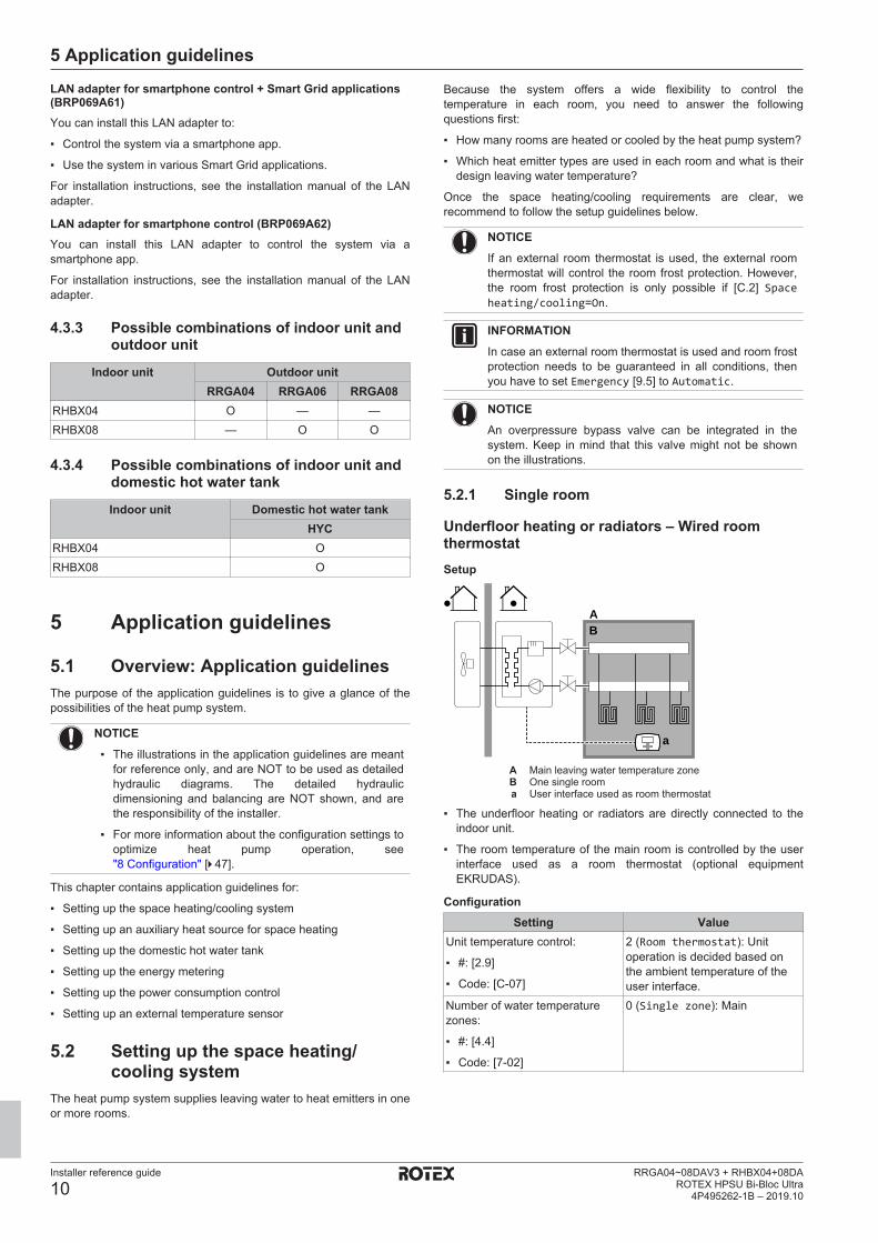
Underfloor heating or radiators – Wired roomthermostatSetup
BA
a
A Main leaving water temperature zoneB One single rooma User interface used as room thermostat
▪ The underfloor heating or radiators are directly connected to theindoor unit.
▪ The room temperature of the main room is controlled by the userinterface used as a room thermostat (optional equipmentEKRUDAS).
ConfigurationSetting Value
Unit temperature control:
▪ #: [2.9]
▪ Code: [C-07]
2 (Room thermostat): Unitoperation is decided based onthe ambient temperature of theuser interface.
Number of water temperaturezones:
▪ #: [4.4]
▪ Code: [7-02]
0 (Single zone): Main
5 Application guidelines
Installer reference guide
11RRGA04~08DAV3 + RHBX04+08DAROTEX HPSU Bi-Bloc Ultra4P495262-1B – 2019.10
Benefits▪ Highest comfort and efficiency. The smart room thermostat
functionality can decrease or increase the desired leaving watertemperature based on the actual room temperature (modulation).This results in:
▪ Stable room temperature matching the desired temperature(higher comfort)
▪ Less ON/OFF cycles (more quiet, higher comfort and higherefficiency)
▪ Lowest possible leaving water temperature (higher efficiency)
▪ Easy. You can easily set the desired room temperature via theuser interface:
▪ For your daily needs, you can use preset values and schedules.
▪ To deviate from your daily needs, you can temporarily overrulethe preset values and schedules, or use the holiday mode.
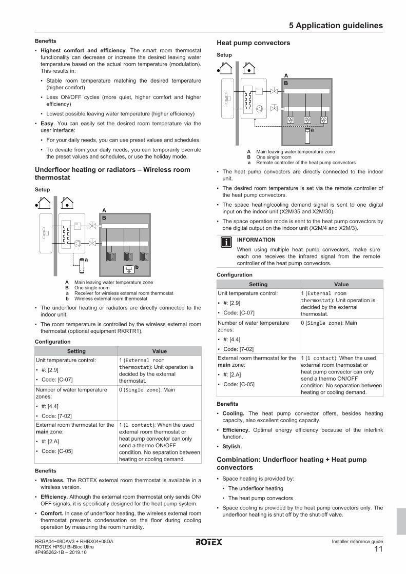
Underfloor heating or radiators – Wireless roomthermostatSetup
BA
ba
A Main leaving water temperature zoneB One single rooma Receiver for wireless external room thermostatb Wireless external room thermostat
▪ The underfloor heating or radiators are directly connected to theindoor unit.
▪ The room temperature is controlled by the wireless external roomthermostat (optional equipment RKRTR1).
ConfigurationSetting Value
Unit temperature control:
▪ #: [2.9]
▪ Code: [C-07]
1 (External roomthermostat): Unit operation isdecided by the externalthermostat.
Number of water temperaturezones:
▪ #: [4.4]
▪ Code: [7-02]
0 (Single zone): Main
External room thermostat for themain zone:
▪ #: [2.A]
▪ Code: [C-05]
1 (1 contact): When the usedexternal room thermostat orheat pump convector can onlysend a thermo ON/OFFcondition. No separation betweenheating or cooling demand.
Benefits▪ Wireless. The ROTEX external room thermostat is available in a
wireless version.
▪ Efficiency. Although the external room thermostat only sends ON/OFF signals, it is specifically designed for the heat pump system.
▪ Comfort. In case of underfloor heating, the wireless external roomthermostat prevents condensation on the floor during coolingoperation by measuring the room humidity.
Heat pump convectorsSetup
BA
a
A Main leaving water temperature zoneB One single rooma Remote controller of the heat pump convectors
▪ The heat pump convectors are directly connected to the indoorunit.
▪ The desired room temperature is set via the remote controller ofthe heat pump convectors.
▪ The space heating/cooling demand signal is sent to one digitalinput on the indoor unit (X2M/35 and X2M/30).
▪ The space operation mode is sent to the heat pump convectors byone digital output on the indoor unit (X2M/4 and X2M/3).
INFORMATIONWhen using multiple heat pump convectors, make sureeach one receives the infrared signal from the remotecontroller of the heat pump convectors.
ConfigurationSetting Value
Unit temperature control:
▪ #: [2.9]
▪ Code: [C-07]
1 (External roomthermostat): Unit operation isdecided by the externalthermostat.
Number of water temperaturezones:
▪ #: [4.4]
▪ Code: [7-02]
0 (Single zone): Main
External room thermostat for themain zone:
▪ #: [2.A]
▪ Code: [C-05]
1 (1 contact): When the usedexternal room thermostat orheat pump convector can onlysend a thermo ON/OFFcondition. No separation betweenheating or cooling demand.
Benefits▪ Cooling. The heat pump convector offers, besides heating
capacity, also excellent cooling capacity.
▪ Efficiency. Optimal energy efficiency because of the interlinkfunction.
▪ Stylish.
Combination: Underfloor heating + Heat pumpconvectors▪ Space heating is provided by:
▪ The underfloor heating
▪ The heat pump convectors
▪ Space cooling is provided by the heat pump convectors only. Theunderfloor heating is shut off by the shut-off valve.
5 Application guidelines
Installer reference guide
12RRGA04~08DAV3 + RHBX04+08DA
ROTEX HPSU Bi-Bloc Ultra4P495262-1B – 2019.10
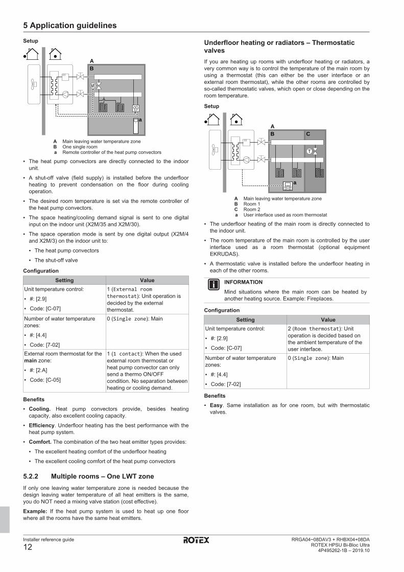
Setup
BA
a
M1
A Main leaving water temperature zoneB One single rooma Remote controller of the heat pump convectors
▪ The heat pump convectors are directly connected to the indoorunit.
▪ A shut-off valve (field supply) is installed before the underfloorheating to prevent condensation on the floor during coolingoperation.
▪ The desired room temperature is set via the remote controller ofthe heat pump convectors.
▪ The space heating/cooling demand signal is sent to one digitalinput on the indoor unit (X2M/35 and X2M/30).
▪ The space operation mode is sent by one digital output (X2M/4and X2M/3) on the indoor unit to:
▪ The heat pump convectors
▪ The shut-off valve
ConfigurationSetting Value
Unit temperature control:
▪ #: [2.9]
▪ Code: [C-07]
1 (External roomthermostat): Unit operation isdecided by the externalthermostat.
Number of water temperaturezones:
▪ #: [4.4]
▪ Code: [7-02]
0 (Single zone): Main
External room thermostat for themain zone:
▪ #: [2.A]
▪ Code: [C-05]
1 (1 contact): When the usedexternal room thermostat orheat pump convector can onlysend a thermo ON/OFFcondition. No separation betweenheating or cooling demand.
Benefits▪ Cooling. Heat pump convectors provide, besides heating
capacity, also excellent cooling capacity.
▪ Efficiency. Underfloor heating has the best performance with theheat pump system.
▪ Comfort. The combination of the two heat emitter types provides:
▪ The excellent heating comfort of the underfloor heating
▪ The excellent cooling comfort of the heat pump convectors
5.2.2 Multiple rooms – One LWT zoneIf only one leaving water temperature zone is needed because thedesign leaving water temperature of all heat emitters is the same,you do NOT need a mixing valve station (cost effective).
Example: If the heat pump system is used to heat up one floorwhere all the rooms have the same heat emitters.
Underfloor heating or radiators – ThermostaticvalvesIf you are heating up rooms with underfloor heating or radiators, avery common way is to control the temperature of the main room byusing a thermostat (this can either be the user interface or anexternal room thermostat), while the other rooms are controlled byso-called thermostatic valves, which open or close depending on theroom temperature.
Setup
T
B CA
a
A Main leaving water temperature zoneB Room 1C Room 2a User interface used as room thermostat
▪ The underfloor heating of the main room is directly connected tothe indoor unit.
▪ The room temperature of the main room is controlled by the userinterface used as a room thermostat (optional equipmentEKRUDAS).
▪ A thermostatic valve is installed before the underfloor heating ineach of the other rooms.
INFORMATIONMind situations where the main room can be heated byanother heating source. Example: Fireplaces.
ConfigurationSetting Value
Unit temperature control:
▪ #: [2.9]
▪ Code: [C-07]
2 (Room thermostat): Unitoperation is decided based onthe ambient temperature of theuser interface.
Number of water temperaturezones:
▪ #: [4.4]
▪ Code: [7-02]
0 (Single zone): Main
Benefits▪ Easy. Same installation as for one room, but with thermostatic
valves.
5 Application guidelines
Installer reference guide
13RRGA04~08DAV3 + RHBX04+08DAROTEX HPSU Bi-Bloc Ultra4P495262-1B – 2019.10
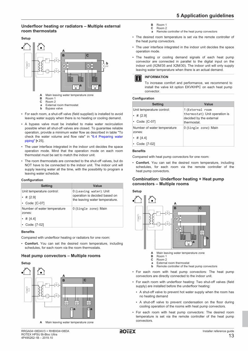
Underfloor heating or radiators – Multiple externalroom thermostatsSetup
M2M1
B CA
a a
b
A Main leaving water temperature zoneB Room 1C Room 2a External room thermostatb Bypass valve
▪ For each room, a shut-off valve (field supplied) is installed to avoidleaving water supply when there is no heating or cooling demand.
▪ A bypass valve must be installed to make water recirculationpossible when all shut-off valves are closed. To guarantee reliableoperation, provide a minimum water flow as described in table "Tocheck the water volume and flow rate" in "6.4 Preparing waterpiping" [4 25].
▪ The user interface integrated in the indoor unit decides the spaceoperation mode. Mind that the operation mode on each roomthermostat must be set to match the indoor unit.
▪ The room thermostats are connected to the shut-off valves, but doNOT have to be connected to the indoor unit. The indoor unit willsupply leaving water all the time, with the possibility to program aleaving water schedule.
ConfigurationSetting Value
Unit temperature control:
▪ #: [2.9]
▪ Code: [C-07]
0 (Leaving water): Unitoperation is decided based onthe leaving water temperature.
Number of water temperaturezones:
▪ #: [4.4]
▪ Code: [7-02]
0 (Single zone): Main
BenefitsCompared with underfloor heating or radiators for one room:
▪ Comfort. You can set the desired room temperature, includingschedules, for each room via the room thermostats.
Heat pump convectors – Multiple roomsSetup
BA
a a
C
A Main leaving water temperature zone
B Room 1C Room 2a Remote controller of the heat pump convectors
▪ The desired room temperature is set via the remote controller ofthe heat pump convectors.
▪ The user interface integrated in the indoor unit decides the spaceoperation mode.
▪ The heating or cooling demand signals of each heat pumpconvector are connected in parallel to the digital input on theindoor unit (X2M/35 and X2M/30). The indoor unit will only supplyleaving water temperature when there is an actual demand.
INFORMATIONTo increase comfort and performance, we recommend toinstall the valve kit option EKVKHPC on each heat pumpconvector.
ConfigurationSetting Value
Unit temperature control:
▪ #: [2.9]
▪ Code: [C-07]
1 (External roomthermostat): Unit operation isdecided by the externalthermostat.
Number of water temperaturezones:
▪ #: [4.4]
▪ Code: [7-02]
0 (Single zone): Main
BenefitsCompared with heat pump convectors for one room:
▪ Comfort. You can set the desired room temperature, includingschedules, for each room via the remote controller of theheat pump convectors.
Combination: Underfloor heating + Heat pumpconvectors – Multiple roomsSetup
b
B CA
a
M1
M1
A Main leaving water temperature zoneB Room 1C Room 2a External room thermostatb Remote controller of the heat pump convectors
▪ For each room with heat pump convectors: The heat pumpconvectors are directly connected to the indoor unit.
▪ For each room with underfloor heating: Two shut-off valves (fieldsupply) are installed before the underfloor heating:
▪ A shut-off valve to prevent hot water supply when the room hasno heating demand
▪ A shut-off valve to prevent condensation on the floor duringcooling operation of the rooms with heat pump convectors.
▪ For each room with heat pump convectors: The desired roomtemperature is set via the remote controller of the heat pumpconvectors.

5 Application guidelines
Installer reference guide
14RRGA04~08DAV3 + RHBX04+08DA
ROTEX HPSU Bi-Bloc Ultra4P495262-1B – 2019.10
▪ For each room with underfloor heating: The desired roomtemperature is set via the external room thermostat (wired orwireless).
▪ The user interface integrated in the indoor unit decides the spaceoperation mode. Mind that the operation mode on each externalroom thermostat and remote controller of the heat pumpconvectors must be set to match the indoor unit.
INFORMATIONTo increase comfort and performance, we recommend toinstall the valve kit option EKVKHPC on each heat pumpconvector.
ConfigurationSetting Value
Unit temperature control:
▪ #: [2.9]
▪ Code: [C-07]
0 (Leaving water): Unitoperation is decided based onthe leaving water temperature.
Number of water temperaturezones:
▪ #: [4.4]
▪ Code: [7-02]
0 (Single zone): Main
5.2.3 Multiple rooms – Two LWT zonesIf the heat emitters selected for each room are designed for differentleaving water temperatures, you can use different leaving watertemperature zones (maximum 2).
In this document:
▪ Main zone = Zone with the lowest design temperature in heating,and the highest design temperature in cooling
▪ Additional zone = Zone with the highest design temperature inheating, and the lowest design temperature in cooling
CAUTIONIf there is more than one leaving water zone, ALWAYSinstall a mixing valve station in the main zone to decrease(in heating)/increase (in cooling) the leaving watertemperature when the additional zone has demand.
Typical example:
Room (zone) Heat emitters: Designtemperature
Living room (main zone) Underfloor heating:
▪ In heating: 35°C
▪ In cooling: 20°C (onlyrefreshment, no real coolingallowed)
Bed rooms (additional zone) Heat pump convectors:
▪ In heating: 45°C
▪ In cooling: 12°C
Setup
BA
a a
C
ED
b
cd
A Additional leaving water temperature zoneB Room 1C Room 2D Main leaving water temperature zoneE Room 3a Remote controller of the heat pump convectorsb User interface used as room thermostatc Mixing valve stationd Pressure regulating valve
INFORMATIONA pressure regulating valve should be implemented beforethe mixing valve station. This is to guarantee the correctwater flow balance between the main leaving watertemperature zone and the additional leaving watertemperature zone in relation to the required capacity ofboth water temperature zones.
▪ For the main zone:
▪ A mixing valve station is installed before the underfloor heating.
▪ The pump of the mixing valve station is controlled by the ON/OFF signal on the indoor unit (X2M/29 and X2M/21; normallyclosed shut-off valve output).
▪ The room temperature is controlled by the user interface, whichis used as room thermostat (optional equipment EKRUDAS).
▪ For the additional zone:
▪ The heat pump convectors are directly connected to the indoorunit.
▪ The desired room temperature is set via the remote controller ofthe heat pump convectors for each room.
▪ The heating or cooling demand signals of each heat pumpconvector are connected in parallel to the digital input on theindoor unit (X2M/35 and X2M/30). The indoor unit will onlysupply the desired additional leaving water temperature whenthere is an actual demand.
▪ The user interface integrated in the indoor unit decides the spaceoperation mode. Mind that the operation mode on each remotecontroller of the heat pump convectors must be set to match theindoor unit.
5 Application guidelines
Installer reference guide
15RRGA04~08DAV3 + RHBX04+08DAROTEX HPSU Bi-Bloc Ultra4P495262-1B – 2019.10
ConfigurationSetting Value
Unit temperature control:
▪ #: [2.9]
▪ Code: [C-07]
2 (Room thermostat): Unitoperation is decided based onthe ambient temperature of theuser interface.
Note:▪ Main room = user interface
used as room thermostatfunctionality
▪ Other rooms = external roomthermostat functionality
Number of water temperaturezones:
▪ #: [4.4]
▪ Code: [7-02]
1 (Dual zone): Main + additional
In case of heat pump convectors:
External room thermostat for theadditional zone:
▪ #: [3.A]
▪ Code: [C-06]
1 (1 contact): When the usedexternal room thermostat orheat pump convector can onlysend a thermo ON/OFFcondition. No separation betweenheating or cooling demand.
Shut-off valve output Set to follow the thermo demandof the main zone.
Shut-off valve If the main zone must be shut offduring cooling mode to preventcondensation on the floor, set itaccordingly.
At the mixing valve station Set the desired main leavingwater temperature for heatingand/or cooling.
Benefits▪ Comfort.
▪ The smart room thermostat functionality can decrease orincrease the desired leaving water temperature based on theactual room temperature (modulation).
▪ The combination of the two heat emitter systems provides theexcellent heating comfort of the underfloor heating, and theexcellent cooling comfort of the heat pump convectors.
▪ Efficiency.▪ Depending on the demand, the indoor unit supplies different
leaving water temperature matching the design temperature ofthe different heat emitters.
▪ Underfloor heating has the best performance with the heatpump system.
5.3 Setting up an auxiliary heat sourcefor space heating
▪ Space heating can be done by:
▪ The indoor unit
▪ An auxiliary boiler (field supply) connected to the system
▪ When the room thermostat requests heating, the indoor unit or theauxiliary boiler starts operating depending on the outdoortemperature (status of the changeover to external heat source).When the permission is given to the auxiliary boiler, the spaceheating by the indoor unit is turned OFF.
▪ Bivalent operation is only possible for space heating, NOT fordomestic hot water production. Domestic hot water is alwaysproduced by the DHW tank connected to the indoor unit.
INFORMATION▪ During heating operation of the heat pump, the
heat pump operates to achieve the desiredtemperature set via the user interface. When weather-dependent operation is active, the water temperature isdetermined automatically depending on the outdoortemperature.
▪ During heating operation of the auxiliary boiler, theauxiliary boiler operates to achieve the desired watertemperature set via the auxiliary boiler controller.
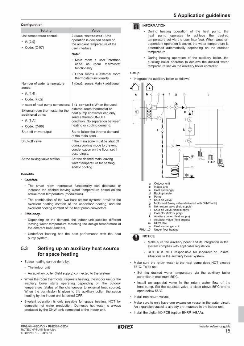
Setup▪ Integrate the auxiliary boiler as follows:
a b c d e f g h j
FHL1FHL2
FHL3
M
h
i
il
kf
m
n
a Outdoor unitb Indoor unitc Heat exchangerd Backup heatere Pumpf Shut-off valveg Motorised 3‑way valve (delivered with DHW tank)h Non-return valve (field supply)i Shut-off valve (field supply)j Collector (field supply)
k Auxiliary boiler (field supply)l Aquastat valve (field supply)
m DHW tankn Heat exchanger coil
FHL1...3 Under floor heating
NOTICE▪ Make sure the auxiliary boiler and its integration in the
system complies with applicable legislation.
▪ ROTEX is NOT responsible for incorrect or unsafesituations in the auxiliary boiler system.
▪ Make sure the return water to the heat pump does NOT exceed55°C. To do so:
▪ Set the desired water temperature via the auxiliary boilercontroller to maximum 55°C.
▪ Install an aquastat valve in the return water flow of theheat pump. Set the aquastat valve to close above 55°C and toopen below 55°C.
▪ Install non-return valves.
▪ Make sure to only have one expansion vessel in the water circuit.An expansion vessel is already pre-mounted in the indoor unit.
▪ Install the digital I/O PCB (option EKRP1HBAA).
5 Application guidelines
Installer reference guide
16RRGA04~08DAV3 + RHBX04+08DA
ROTEX HPSU Bi-Bloc Ultra4P495262-1B – 2019.10
▪ Connect X1 and X2 (changeover to external heat source) on thedigital I/O PCB to the auxiliary boiler thermostat. See "7.9.15 Toconnect the changeover to external heat source" [4 46].
▪ To setup the heat emitters, see "5.2 Setting up the space heating/cooling system" [4 10].
ConfigurationVia the user interface (configuration wizard):
▪ Set the use of a bivalent system as external heat source.
▪ Set the bivalent temperature and hysteresis.
NOTICE▪ Make sure the bivalent hysteresis has enough
differential to prevent frequent changeover betweenindoor unit and auxiliary boiler.
▪ Because the outdoor temperature is measured by theoutdoor unit air thermistor, install the outdoor unit in theshadow so that it is NOT influenced or turned ON/OFFby direct sunlight.
▪ Frequent changeover may cause corrosion of theauxiliary boiler. Contact the manufacturer of theauxiliary boiler for more information.
Changeover to external heat source decided by an auxiliarycontact▪ Only possible in external room thermostat control AND one
leaving water temperature zone (see "5.2 Setting up the spaceheating/cooling system" [4 10]).
▪ The auxiliary contact can be:
▪ An outdoor temperature thermostat
▪ An electricity tariff contact
▪ A manually operated contact
▪ …
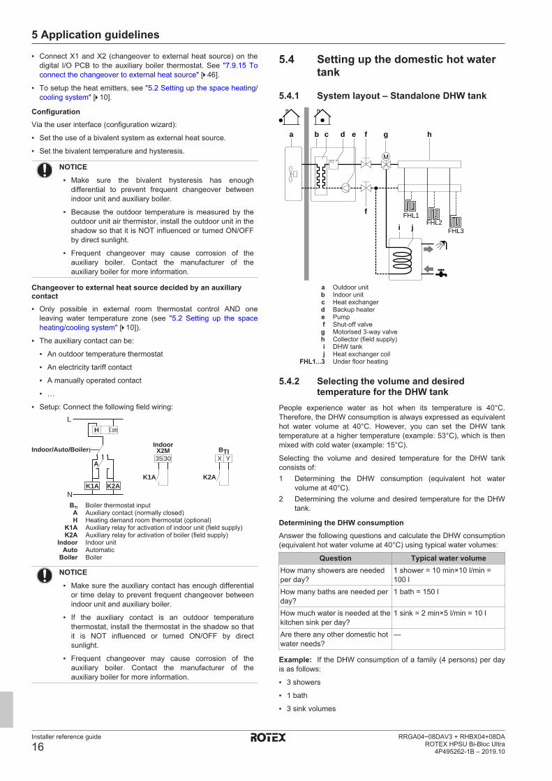
▪ Setup: Connect the following field wiring:L
N
H Com
A
K2AK1A
X2M BTI
K2AK1A
Indoor/Auto/Boiler35 30 X Y
Indoor
BTI Boiler thermostat inputA Auxiliary contact (normally closed)H Heating demand room thermostat (optional)
K1A Auxiliary relay for activation of indoor unit (field supply)K2A Auxiliary relay for activation of boiler (field supply)
Indoor Indoor unitAuto Automatic
Boiler Boiler
NOTICE▪ Make sure the auxiliary contact has enough differential
or time delay to prevent frequent changeover betweenindoor unit and auxiliary boiler.
▪ If the auxiliary contact is an outdoor temperaturethermostat, install the thermostat in the shadow so thatit is NOT influenced or turned ON/OFF by directsunlight.
▪ Frequent changeover may cause corrosion of theauxiliary boiler. Contact the manufacturer of theauxiliary boiler for more information.
5.4 Setting up the domestic hot watertank
5.4.1 System layout – Standalone DHW tank
FHL1FHL2
FHL3
M
a b c d e hf g
f
i j
a Outdoor unitb Indoor unitc Heat exchangerd Backup heatere Pumpf Shut-off valveg Motorised 3‑way valveh Collector (field supply)i DHW tankj Heat exchanger coil
FHL1...3 Under floor heating
5.4.2 Selecting the volume and desiredtemperature for the DHW tank
People experience water as hot when its temperature is 40°C.Therefore, the DHW consumption is always expressed as equivalenthot water volume at 40°C. However, you can set the DHW tanktemperature at a higher temperature (example: 53°C), which is thenmixed with cold water (example: 15°C).
Selecting the volume and desired temperature for the DHW tankconsists of:1 Determining the DHW consumption (equivalent hot water
volume at 40°C).2 Determining the volume and desired temperature for the DHW
tank.
Determining the DHW consumptionAnswer the following questions and calculate the DHW consumption(equivalent hot water volume at 40°C) using typical water volumes:
Question Typical water volumeHow many showers are neededper day?
1 shower = 10 min×10 l/min =100 l
How many baths are needed perday?
1 bath = 150 l
How much water is needed at thekitchen sink per day?
1 sink = 2 min×5 l/min = 10 l
Are there any other domestic hotwater needs?
—
Example: If the DHW consumption of a family (4 persons) per dayis as follows:
▪ 3 showers
▪ 1 bath
▪ 3 sink volumes

5 Application guidelines
Installer reference guide
17RRGA04~08DAV3 + RHBX04+08DAROTEX HPSU Bi-Bloc Ultra4P495262-1B – 2019.10
Then the DHW consumption = (3×100 l)+(1×150 l)+(3×10 l)=480 l
Determining the volume and desired temperature for the DHWtank
Formula ExampleV1=V2+V2×(T2−40)/(40−T1) If:
▪ V2=180 l
▪ T2=54°C
▪ T1=15°C
Then V1=280 lV2=V1×(40−T1)/(T2−T1) If:
▪ V1=480 l
▪ T2=54°C
▪ T1=15°C
Then V2=307 lV1 DHW consumption (equivalent hot water volume at 40°C)V2 Required DHW tank volume if only heated onceT2 DHW tank temperatureT1 Cold water temperature
Possible DHW tank volumesType Possible volumes
Standalone DHW tank ▪ 150 l
▪ 180 l
▪ 200 l
▪ 250 l
▪ 300 l (polypropylene tank iscompatible with solar kit)
▪ 500 l (compatible with solar kit)
Energy saving tips▪ If the DHW consumption differs from day to day, you can program
a weekly schedule with different desired DHW tank temperaturesfor each day.
▪ The lower the desired DHW tank temperature, the more costeffective. By selecting a larger DHW tank, you can lower thedesired DHW tank temperature.
▪ The heat pump itself can produce domestic hot water of maximum55°C (50°C if outdoor temperature is low). The electricalresistance integrated in the heat pump can increase thistemperature. However, this consumes more energy. Werecommend to set the desired DHW tank temperature below 55°Cto avoid using the electrical resistance.
▪ The higher the outdoor temperature, the better the performance ofthe heat pump.
▪ If energy prices are the same during the day and the night, werecommend to heat up the DHW tank during the day.
▪ If energy prices are lower during the night, we recommend toheat up the DHW tank during the night.
▪ When the heat pump produces domestic hot water, it cannot heatup a space. In case you need domestic hot water and spaceheating at the same, we recommend to produce the domestic hotwater during the night when there is lower space heating demand.
5.4.3 Setup and configuration – DHW tank▪ For large DHW consumptions, you can heat up the DHW tank
several times during the day.
▪ To heat up the DHW tank to the desired DHW tank temperature,you can use the following energy sources:
▪ Thermodynamic cycle of the heat pump
▪ Electrical booster heater
▪ For more information about:
▪ Optimizing the energy consumption for producing domestic hotwater, see "8 Configuration" [4 47].
▪ Connecting the electrical wiring of the standalone DHW tank tothe indoor unit, see the installation manual of the DHW tank,and the addendum book for optional equipment.
▪ Connecting the water piping of the standalone DHW tank to theindoor unit, see the installation manual of the DHW tank.
5.4.4 DHW pump for instant hot waterSetup
fab
g
h
i c
a Indoor unitb DHW tankc DHW pump (field supply)f Shower (field supply)g Cold waterh Domestic hot water OUTi Recirculation connection
▪ By connecting a DHW pump, instant hot water can be available atthe tap.
▪ The DHW pump and the installation are field supply and theresponsibility of the installer. For the electrical wiring, see"7.9.12 To connect the domestic hot water pump" [4 45].
▪ For more information about connecting the recirculationconnection, see the installation manual of the domestic hot watertank.
Configuration▪ For more information, see "8 Configuration" [4 47].
▪ You can program a schedule to control the DHW pump via theuser interface. For more information, see the user referenceguide.
5.4.5 DHW pump for disinfectionSetup
cab
d f
e g
h
i
a Indoor unitb DHW tankc DHW pump (field supply)d Heater element (field supply)e Non‑return valve (field supply)f Shower (field supply)g Cold waterh Domestic hot water OUTi Recirculation connection
▪ The DHW pump is field-supplied and its installation is theresponsibility of the installer. For the electrical wiring, see"7.9.12 To connect the domestic hot water pump" [4 45].
▪ If the applicable legislation requires a higher temperature than themaximum tank setpoint during disinfection (see [2-03] in the fieldsettings table), you can connect a DHW pump and heater elementas shown above.
▪ If applicable legislation requires disinfection of the water pipinguntil the tapping point, you can connect a DHW pump and heaterelement (if needed) as shown above.
5 Application guidelines
Installer reference guide
18RRGA04~08DAV3 + RHBX04+08DA
ROTEX HPSU Bi-Bloc Ultra4P495262-1B – 2019.10
ConfigurationThe indoor unit can control DHW pump operation. For moreinformation, see "8 Configuration" [4 47].
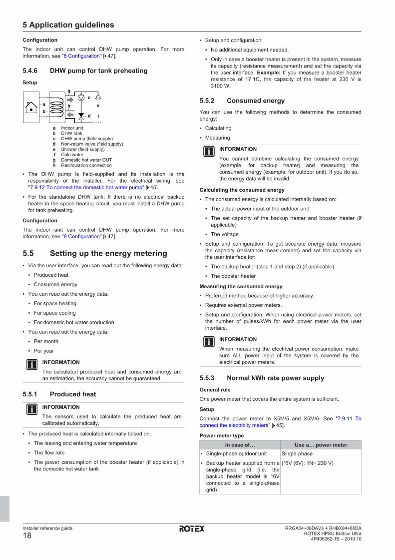
5.4.6 DHW pump for tank preheatingSetup
cab
e
d f
g
h
a Indoor unitb DHW tankc DHW pump (field supply)d Non‑return valve (field supply)e Shower (field supply)f Cold waterg Domestic hot water OUTh Recirculation connection
▪ The DHW pump is field-supplied and its installation is theresponsibility of the installer. For the electrical wiring, see"7.9.12 To connect the domestic hot water pump" [4 45].
▪ For the standalone DHW tank: If there is no electrical backupheater in the space heating circuit, you must install a DHW pumpfor tank preheating.
ConfigurationThe indoor unit can control DHW pump operation. For moreinformation, see "8 Configuration" [4 47].
5.5 Setting up the energy metering▪ Via the user interface, you can read out the following energy data:
▪ Produced heat
▪ Consumed energy
▪ You can read out the energy data:
▪ For space heating
▪ For space cooling
▪ For domestic hot water production
▪ You can read out the energy data:
▪ Per month
▪ Per year
INFORMATIONThe calculated produced heat and consumed energy arean estimation, the accuracy cannot be guaranteed.
5.5.1 Produced heat
INFORMATIONThe sensors used to calculate the produced heat arecalibrated automatically.
▪ The produced heat is calculated internally based on:
▪ The leaving and entering water temperature
▪ The flow rate
▪ The power consumption of the booster heater (if applicable) inthe domestic hot water tank
▪ Setup and configuration:
▪ No additional equipment needed.
▪ Only in case a booster heater is present in the system, measureits capacity (resistance measurement) and set the capacity viathe user interface. Example: If you measure a booster heaterresistance of 17.1Ω, the capacity of the heater at 230 V is3100 W.
5.5.2 Consumed energyYou can use the following methods to determine the consumedenergy:
▪ Calculating
▪ Measuring
INFORMATIONYou cannot combine calculating the consumed energy(example: for backup heater) and measuring theconsumed energy (example: for outdoor unit). If you do so,the energy data will be invalid.
Calculating the consumed energy▪ The consumed energy is calculated internally based on:
▪ The actual power input of the outdoor unit
▪ The set capacity of the backup heater and booster heater (ifapplicable)
▪ The voltage
▪ Setup and configuration: To get accurate energy data, measurethe capacity (resistance measurement) and set the capacity viathe user interface for:
▪ The backup heater (step 1 and step 2) (if applicable)
▪ The booster heater
Measuring the consumed energy▪ Preferred method because of higher accuracy.
▪ Requires external power meters.
▪ Setup and configuration: When using electrical power meters, setthe number of pulses/kWh for each power meter via the userinterface.
INFORMATIONWhen measuring the electrical power consumption, makesure ALL power input of the system is covered by theelectrical power meters.
5.5.3 Normal kWh rate power supplyGeneral ruleOne power meter that covers the entire system is sufficient.
SetupConnect the power meter to X5M/5 and X5M/6. See "7.9.11 Toconnect the electricity meters" [4 45].
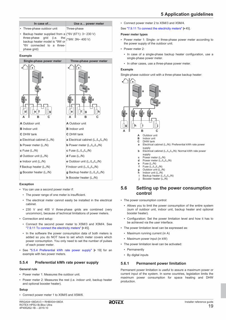
Power meter typeIn case of… Use a… power meter
▪ Single-phase outdoor unit
▪ Backup heater supplied from asingle-phase grid (i.e. thebackup heater model is *6Vconnected to a single-phasegrid)
Single-phase
(*6V (6V): 1N~ 230 V)
5 Application guidelines
Installer reference guide
19RRGA04~08DAV3 + RHBX04+08DAROTEX HPSU Bi-Bloc Ultra4P495262-1B – 2019.10
In case of… Use a… power meter▪ Three-phase outdoor unit
▪ Backup heater supplied from athree-phase grid (i.e. thebackup heater model is *9W or*6V connected to a three-phase grid)
Three-phase
(*6V (6T1): 3~ 230 V)
(*9W: 3N~ 400 V)
ExampleSingle-phase power meter Three-phase power meter
b
5801 5000
c c
fed g
A B C
a
A Outdoor unit
B Indoor unit
C DHW tank
a Electrical cabinet (L1/N)
b Power meter (L1/N)
c Fuse (L1/N)
d Outdoor unit (L1/N)
e Indoor unit (L1/N)
f Backup heater (L1/N)
g Booster heater (L1/N)
b
5801 5000
gfe h
A B C
c c d
a
A Outdoor unit
B Indoor unit
C DHW tank
a Electrical cabinet (L1/L2/L3/N)
b Power meter (L1/L2/L3/N)
c Fuse (L1/L2/L3/N)
d Fuse (L1/N)
e Outdoor unit (L1/L2/L3/N)
f Indoor unit (L1/L2/L3/N)
g Backup heater (L1/L2/L3/N)
h Booster heater (L1/N)
Exception▪ You can use a second power meter if:
▪ The power range of one meter is insufficient.
▪ The electrical meter cannot easily be installed in the electricalcabinet.
▪ 230 V and 400 V three-phase grids are combined (veryuncommon), because of technical limitations of power meters.
▪ Connection and setup:
▪ Connect the second power meter to X5M/3 and X5M/4. See"7.9.11 To connect the electricity meters" [4 45].
▪ In the software the power consumption data of both meters isadded so you do NOT have to set which meter covers whichpower consumption. You only need to set the number of pulsesof each power meter.
▪ See "5.5.4 Preferential kWh rate power supply" [4 19] for anexample with two power meters.
5.5.4 Preferential kWh rate power supplyGeneral rule▪ Power meter 1: Measures the outdoor unit.
▪ Power meter 2: Measures the rest (i.e. indoor unit, backup heaterand optional booster heater).
Setup▪ Connect power meter 1 to X5M/5 and X5M/6.
▪ Connect power meter 2 to X5M/3 and X5M/4.
See "7.9.11 To connect the electricity meters" [4 45].
Power meter types▪ Power meter 1: Single- or three-phase power meter according to
the power supply of the outdoor unit.
▪ Power meter 2:
▪ In case of a single-phase backup heater configuration, use asingle-phase power meter.
▪ In other cases, use a three-phase power meter.
ExampleSingle-phase outdoor unit with a three-phase backup heater:
e efe
ihg j
A B C
ba
dc
5801 5000 5801 50
00
A Outdoor unitB Indoor unitC DHW tanka Electrical cabinet (L1/N): Preferential kWh rate power
supplyb Electrical cabinet (L1/L2/L3/N): Normal kWh rate power
supplyc Power meter (L1/N)d Power meter (L1/L2/L3/N)e Fuse (L1/N)f Fuse (L1/L2/L3/N)g Outdoor unit (L1/N)h Indoor unit (L1/N)i Backup heater (L1/L2/L3/N)j Booster heater (L1/N)
5.6 Setting up the power consumptioncontrol
▪ The power consumption control:
▪ Allows you to limit the power consumption of the entire system(sum of outdoor unit, indoor unit, backup heater and optionalbooster heater).
▪ Configuration: Set the power limitation level and how it has tobe achieved via the user interface.
▪ The power limitation level can be expressed as:
▪ Maximum running current (in A)
▪ Maximum power input (in kW)
▪ The power limitation level can be activated:
▪ Permanently
▪ By digital inputs
5.6.1 Permanent power limitationPermanent power limitation is useful to assure a maximum power orcurrent input of the system. In some countries, legislation limits themaximum power consumption for space heating and DHWproduction.
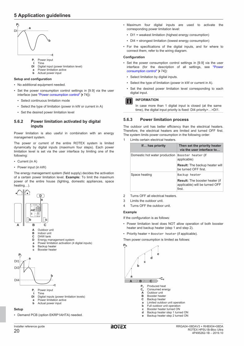
5 Application guidelines
Installer reference guide
20RRGA04~08DAV3 + RHBX04+08DA
ROTEX HPSU Bi-Bloc Ultra4P495262-1B – 2019.10
Pi
t
DIa
b
Pi Power inputt Time
DI Digital input (power limitation level)a Power limitation activeb Actual power input
Setup and configuration▪ No additional equipment needed.
▪ Set the power consumption control settings in [9.9] via the userinterface (see "Power consumption control" [4 74]):
▪ Select continuous limitation mode
▪ Select the type of limitation (power in kW or current in A)
▪ Set the desired power limitation level
5.6.2 Power limitation activated by digitalinputs
Power limitation is also useful in combination with an energymanagement system.
The power or current of the entire ROTEX system is limiteddynamically by digital inputs (maximum four steps). Each powerlimitation level is set via the user interface by limiting one of thefollowing:
▪ Current (in A)
▪ Power input (in kW)
The energy management system (field supply) decides the activationof a certain power limitation level. Example: To limit the maximumpower of the entire house (lighting, domestic appliances, spaceheating…).
a
b cA B C
D
12345
A8P
A Outdoor unitB Indoor unitC DHW tankD Energy management systema Power limitation activation (4 digital inputs)b Backup heaterc Booster heater
Pi
tDI4
DI3
DI1a
b
Pi Power inputt Time
DI Digital inputs (power limitation levels)a Power limitation activeb Actual power input
Setup▪ Demand PCB (option EKRP1AHTA) needed.
▪ Maximum four digital inputs are used to activate thecorresponding power limitation level:
▪ DI1 = weakest limitation (highest energy consumption)
▪ DI4 = strongest limitation (lowest energy consumption)
▪ For the specifications of the digital inputs, and for where toconnect them, refer to the wiring diagram.
Configuration▪ Set the power consumption control settings in [9.9] via the user
interface (for the description of all settings, see "Powerconsumption control" [4 74]):
▪ Select limitation by digital inputs.
▪ Select the type of limitation (power in kW or current in A).
▪ Set the desired power limitation level corresponding to eachdigital input.
INFORMATIONIn case more than 1 digital input is closed (at the sametime), the digital input priority is fixed: DI4 priority>…>DI1.
5.6.3 Power limitation processThe outdoor unit has better efficiency than the electrical heaters.Therefore, the electrical heaters are limited and turned OFF first.The system limits power consumption in the following order:1 Limits certain electrical heaters.
If… has priority Then set the priority heatervia the user interface to…
Domestic hot water production Booster heater (ifapplicable)
Result: The backup heater willbe turned OFF first.
Space heating Backup heater
Result: The booster heater (ifapplicable) will be turned OFFfirst.
2 Turns OFF all electrical heaters.3 Limits the outdoor unit.4 Turns OFF the outdoor unit.
ExampleIf the configuration is as follows:
▪ Power limitation level does NOT allow operation of both boosterheater and backup heater (step 1 and step 2).
▪ Priority heater = Booster heater (if applicable).
Then power consumption is limited as follows:Ph
Cea
bc
de
A B CPh Produced heatCe Consumed energyA Outdoor unitB Booster heaterC Backup heatera Limited outdoor unit operationb Full outdoor unit operationc Booster heater turned ONd Backup heater step 1 turned ONe Backup heater step 2 turned ON
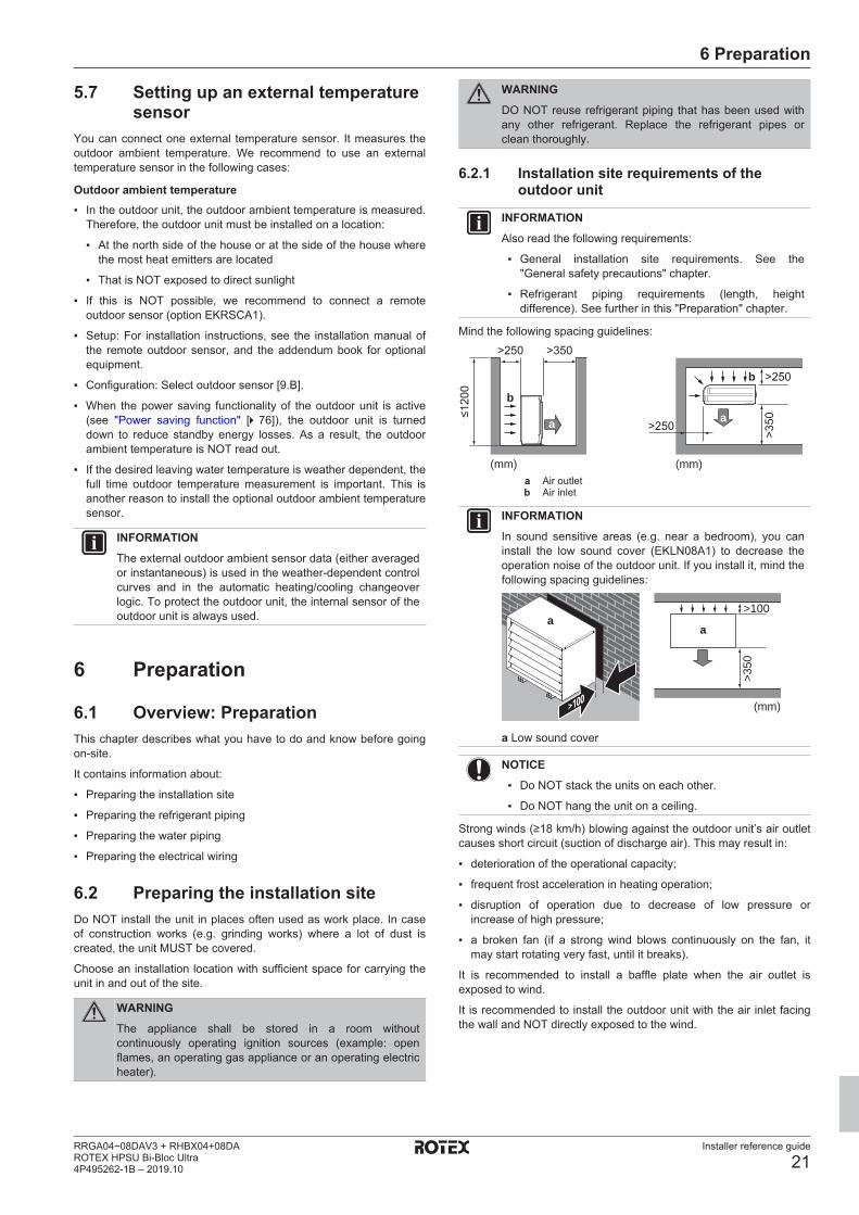
6 Preparation
Installer reference guide
21RRGA04~08DAV3 + RHBX04+08DAROTEX HPSU Bi-Bloc Ultra4P495262-1B – 2019.10
5.7 Setting up an external temperaturesensor
You can connect one external temperature sensor. It measures theoutdoor ambient temperature. We recommend to use an externaltemperature sensor in the following cases:
Outdoor ambient temperature▪ In the outdoor unit, the outdoor ambient temperature is measured.
Therefore, the outdoor unit must be installed on a location:
▪ At the north side of the house or at the side of the house wherethe most heat emitters are located
▪ That is NOT exposed to direct sunlight
▪ If this is NOT possible, we recommend to connect a remoteoutdoor sensor (option EKRSCA1).
▪ Setup: For installation instructions, see the installation manual ofthe remote outdoor sensor, and the addendum book for optionalequipment.
▪ Configuration: Select outdoor sensor [9.B].
▪ When the power saving functionality of the outdoor unit is active(see "Power saving function" [4 76]), the outdoor unit is turneddown to reduce standby energy losses. As a result, the outdoorambient temperature is NOT read out.
▪ If the desired leaving water temperature is weather dependent, thefull time outdoor temperature measurement is important. This isanother reason to install the optional outdoor ambient temperaturesensor.
INFORMATIONThe external outdoor ambient sensor data (either averagedor instantaneous) is used in the weather-dependent controlcurves and in the automatic heating/cooling changeoverlogic. To protect the outdoor unit, the internal sensor of theoutdoor unit is always used.
6 Preparation
6.1 Overview: PreparationThis chapter describes what you have to do and know before goingon-site.
It contains information about:
▪ Preparing the installation site
▪ Preparing the refrigerant piping
▪ Preparing the water piping
▪ Preparing the electrical wiring
6.2 Preparing the installation siteDo NOT install the unit in places often used as work place. In caseof construction works (e.g. grinding works) where a lot of dust iscreated, the unit MUST be covered.
Choose an installation location with sufficient space for carrying theunit in and out of the site.
WARNINGThe appliance shall be stored in a room withoutcontinuously operating ignition sources (example: openflames, an operating gas appliance or an operating electricheater).
WARNINGDO NOT reuse refrigerant piping that has been used withany other refrigerant. Replace the refrigerant pipes orclean thoroughly.
6.2.1 Installation site requirements of theoutdoor unit
INFORMATIONAlso read the following requirements:
▪ General installation site requirements. See the"General safety precautions" chapter.
▪ Refrigerant piping requirements (length, heightdifference). See further in this "Preparation" chapter.
Mind the following spacing guidelines:
≤1200
>250
>250
>250
>350
>350
(mm)(mm)
a
b
b
a
a Air outletb Air inlet
INFORMATIONIn sound sensitive areas (e.g. near a bedroom), you caninstall the low sound cover (EKLN08A1) to decrease theoperation noise of the outdoor unit. If you install it, mind thefollowing spacing guidelines:
>100
>350
(mm)>100
aa
a Low sound cover
NOTICE▪ Do NOT stack the units on each other.
▪ Do NOT hang the unit on a ceiling.
Strong winds (≥18 km/h) blowing against the outdoor unit’s air outletcauses short circuit (suction of discharge air). This may result in:
▪ deterioration of the operational capacity;
▪ frequent frost acceleration in heating operation;
▪ disruption of operation due to decrease of low pressure orincrease of high pressure;
▪ a broken fan (if a strong wind blows continuously on the fan, itmay start rotating very fast, until it breaks).
It is recommended to install a baffle plate when the air outlet isexposed to wind.
It is recommended to install the outdoor unit with the air inlet facingthe wall and NOT directly exposed to the wind.
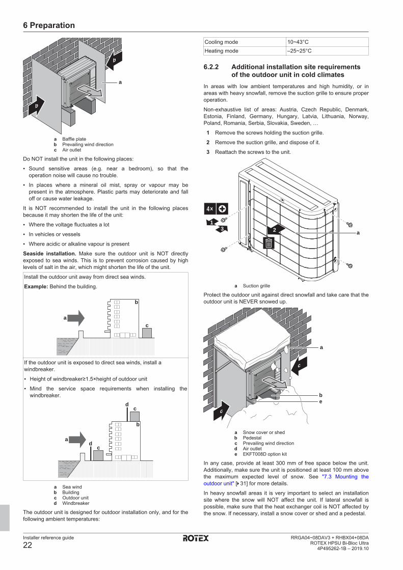
6 Preparation
Installer reference guide
22RRGA04~08DAV3 + RHBX04+08DA
ROTEX HPSU Bi-Bloc Ultra4P495262-1B – 2019.10
b
b
ca
a Baffle plateb Prevailing wind directionc Air outlet
Do NOT install the unit in the following places:
▪ Sound sensitive areas (e.g. near a bedroom), so that theoperation noise will cause no trouble.
▪ In places where a mineral oil mist, spray or vapour may bepresent in the atmosphere. Plastic parts may deteriorate and falloff or cause water leakage.
It is NOT recommended to install the unit in the following placesbecause it may shorten the life of the unit:
▪ Where the voltage fluctuates a lot
▪ In vehicles or vessels
▪ Where acidic or alkaline vapour is present
Seaside installation. Make sure the outdoor unit is NOT directlyexposed to sea winds. This is to prevent corrosion caused by highlevels of salt in the air, which might shorten the life of the unit.
Install the outdoor unit away from direct sea winds.
Example: Behind the building.
b
ca
If the outdoor unit is exposed to direct sea winds, install awindbreaker.
▪ Height of windbreaker≥1.5×height of outdoor unit
▪ Mind the service space requirements when installing thewindbreaker.
a
b
cd
cd
a Sea windb Buildingc Outdoor unitd Windbreaker
The outdoor unit is designed for outdoor installation only, and for thefollowing ambient temperatures:
Cooling mode 10~43°CHeating mode –25~25°C
6.2.2 Additional installation site requirementsof the outdoor unit in cold climates
In areas with low ambient temperatures and high humidity, or inareas with heavy snowfall, remove the suction grille to ensure properoperation.
Non-exhaustive list of areas: Austria, Czech Republic, Denmark,Estonia, Finland, Germany, Hungary, Latvia, Lithuania, Norway,Poland, Romania, Serbia, Slovakia, Sweden, …
1 Remove the screws holding the suction grille.
2 Remove the suction grille, and dispose of it.
3 Reattach the screws to the unit.
2
4×
13
a
a Suction grille
Protect the outdoor unit against direct snowfall and take care that theoutdoor unit is NEVER snowed up.
c
c
d
be
a
a Snow cover or shedb Pedestalc Prevailing wind directiond Air outlete EKFT008D option kit
In any case, provide at least 300 mm of free space below the unit.Additionally, make sure the unit is positioned at least 100 mm abovethe maximum expected level of snow. See "7.3 Mounting theoutdoor unit" [4 31] for more details.
In heavy snowfall areas it is very important to select an installationsite where the snow will NOT affect the unit. If lateral snowfall ispossible, make sure that the heat exchanger coil is NOT affected bythe snow. If necessary, install a snow cover or shed and a pedestal.
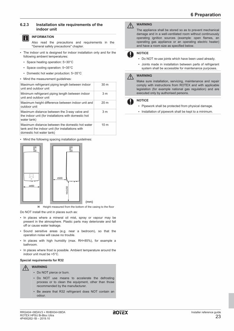
6 Preparation
Installer reference guide
23RRGA04~08DAV3 + RHBX04+08DAROTEX HPSU Bi-Bloc Ultra4P495262-1B – 2019.10
6.2.3 Installation site requirements of theindoor unit
INFORMATIONAlso read the precautions and requirements in the"General safety precautions" chapter.
▪ The indoor unit is designed for indoor installation only and for thefollowing ambient temperatures:
▪ Space heating operation: 5~30°C
▪ Space cooling operation: 5~35°C
▪ Domestic hot water production: 5~35°C
▪ Mind the measurement guidelines:
Maximum refrigerant piping length between indoorunit and outdoor unit
30 m
Minimum refrigerant piping length between indoorunit and outdoor unit
3 m
Maximum height difference between indoor unit andoutdoor unit
20 m
Maximum distance between the 3‑way valve andthe indoor unit (for installations with domestic hotwater tank)
3 m
Maximum distance between the domestic hot watertank and the indoor unit (for installations withdomestic hot water tank)
10 m
▪ Mind the following spacing installation guidelines:
H≥1
150
≥200
≥200
≥500
(mm)
≥450
H Height measured from the bottom of the casing to the floor
Do NOT install the unit in places such as:
▪ In places where a mineral oil mist, spray or vapour may bepresent in the atmosphere. Plastic parts may deteriorate and falloff or cause water leakage.
▪ Sound sensitive areas (e.g. near a bedroom), so that theoperation noise will cause no trouble.
▪ In places with high humidity (max. RH=85%), for example abathroom.
▪ In places where frost is possible. Ambient temperature around theindoor unit must be >5°C.
Special requirements for R32
WARNING▪ Do NOT pierce or burn.
▪ Do NOT use means to accelerate the defrostingprocess or to clean the equipment, other than thoserecommended by the manufacturer.
▪ Be aware that R32 refrigerant does NOT contain anodour.
WARNINGThe appliance shall be stored so as to prevent mechanicaldamage and in a well-ventilated room without continuouslyoperating ignition sources (example: open flames, anoperating gas appliance or an operating electric heater)and have a room size as specified below.
NOTICE▪ Do NOT re-use joints which have been used already.
▪ Joints made in installation between parts of refrigerantsystem shall be accessible for maintenance purposes.
WARNINGMake sure installation, servicing, maintenance and repaircomply with instructions from ROTEX and with applicablelegislation (for example national gas regulation) and areexecuted only by authorised persons.
NOTICE▪ Pipework shall be protected from physical damage.
▪ Installation of pipework shall be kept to a minimum.

6 Preparation
Installer reference guide
24RRGA04~08DAV3 + RHBX04+08DA
ROTEX HPSU Bi-Bloc Ultra4P495262-1B – 2019.10
If the total refrigerant charge in the system is ≥1.84 kg (i.e. if the piping length is ≥27 m), you need to comply with the minimum floor arearequirements as described in the following flow chart. The flow chart uses the following tables: "14.5 Table 1 – Maximum refrigerant chargeallowed in a room: indoor unit" [4 98], "14.6 Table 2 – Minimum floor area: indoor unit" [4 98] and "14.7 Table 3 – Minimum venting openingarea for natural ventilation: indoor unit" [4 99].
INFORMATIONSystems with a total refrigerant charge (mc) <1.84 kg (i.e. ifthe piping length is <27 m) are NOT subjected to anyrequirements to the installation room.
INFORMATIONMultiple indoor units. If two or more indoor units areinstalled in a room, you must consider the maximumrefrigerant charge that can be released in the room when aSINGLE leak occurs. Example: If two indoor units areinstalled in the room, each with its own outdoor unit, thenyou have to consider the refrigerant charge of the largestindoor-outdoor combination.
Input from installer:▪ Total refrigerant charge (mc) (kg)▪ Installation height (H) (m)▪ Area of room A (Aroom A) (m2)
Start
Use table 1 in chapter "Technical data" to calculate the maximum refrigerant charge (mmax) (kg) allowed for room A.
Contact your dealer.Use table 3 in chapter "Technical data" and dm to calculate the minimum opening area for natural ventilation between room A and room B (VAmin) (cm2).
Unit can be installed at room A if:▪ 2 ventilation openings (permanently open) are provided between room A and B, 1 at the top and 1 at the bottom.▪ Bottom opening: The bottom opening must meet the minimum area requirements (VAmin). It must be as close as possible to the floor and lower than H. If the
ventilation opening starts from the floor, the height must be ≥20 mm. The bottom of the opening must be situated ≤100 mm from the floor. At least 50% of the required opening area must be situated <200 mm from the floor. The entire area of the opening must be situated <300 mm from the floor.
▪ Top opening: The area of the top opening must be larger than or equal to the bottom opening. The bottom of the top opening must be situated at least 1.5 m above the top of the bottom opening.
▪ Ventilation openings to the outside are NOT considered suitable ventilation openings (the user can block them when it is cold).
The unit can be installed in room A at the specified installation height, and without further room size or ventilation requirements.
Determine the refrigerant amount that exceeds mmax (dm) (kg). (dm=mc–mmax)
mmax≥mc?
Yes
No
No
Use table 2 in chapter "Technical data" to calculate the total minimum floor area (Amin total) (m
2) required for the total refrigerant charge (mc) at the selected installation height (H).
a Indoor unitA Room where the indoor unit is installed. B Room adjacent to room A.
Amin total≤Aroom A+Aroom B?
Yes
Input from installer:▪ Area of adjacent room B (Aroom B) (m2)
A
a
B
≥1.5
m
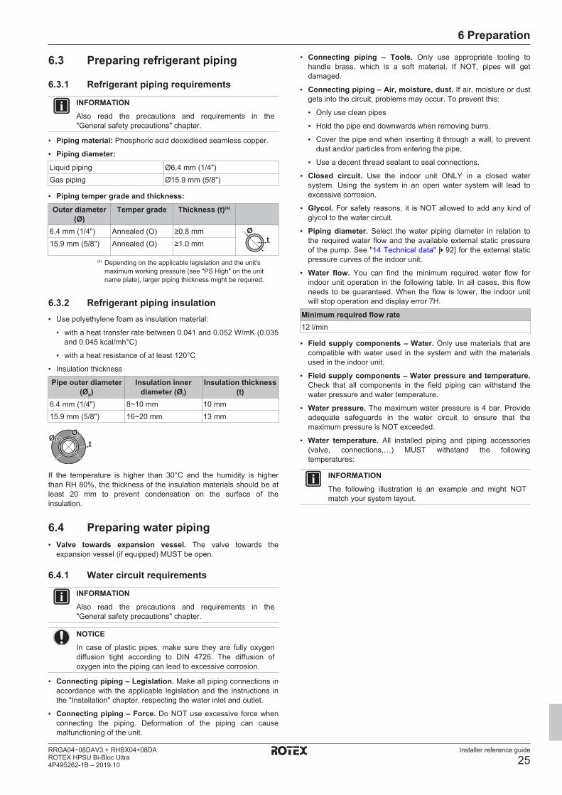
6 Preparation
Installer reference guide
25RRGA04~08DAV3 + RHBX04+08DAROTEX HPSU Bi-Bloc Ultra4P495262-1B – 2019.10
6.3 Preparing refrigerant piping
6.3.1 Refrigerant piping requirements
INFORMATIONAlso read the precautions and requirements in the"General safety precautions" chapter.
▪ Piping material: Phosphoric acid deoxidised seamless copper.
▪ Piping diameter:
Liquid piping Ø6.4 mm (1/4")Gas piping Ø15.9 mm (5/8")
▪ Piping temper grade and thickness:
Outer diameter(Ø)
Temper grade Thickness (t)(a)
6.4 mm (1/4") Annealed (O) ≥0.8 mmt
Ø
15.9 mm (5/8") Annealed (O) ≥1.0 mm
(a) Depending on the applicable legislation and the unit'smaximum working pressure (see "PS High" on the unitname plate), larger piping thickness might be required.
6.3.2 Refrigerant piping insulation▪ Use polyethylene foam as insulation material:
▪ with a heat transfer rate between 0.041 and 0.052 W/mK (0.035and 0.045 kcal/mh°C)
▪ with a heat resistance of at least 120°C
▪ Insulation thickness
Pipe outer diameter(Øp)
Insulation innerdiameter (Øi)
Insulation thickness(t)
6.4 mm (1/4") 8~10 mm 10 mm15.9 mm (5/8") 16~20 mm 13 mm
ØiØi
tØpØp
If the temperature is higher than 30°C and the humidity is higherthan RH 80%, the thickness of the insulation materials should be atleast 20 mm to prevent condensation on the surface of theinsulation.
6.4 Preparing water piping▪ Valve towards expansion vessel. The valve towards the
expansion vessel (if equipped) MUST be open.
6.4.1 Water circuit requirements
INFORMATIONAlso read the precautions and requirements in the"General safety precautions" chapter.
NOTICEIn case of plastic pipes, make sure they are fully oxygendiffusion tight according to DIN 4726. The diffusion ofoxygen into the piping can lead to excessive corrosion.
▪ Connecting piping – Legislation. Make all piping connections inaccordance with the applicable legislation and the instructions inthe "Installation" chapter, respecting the water inlet and outlet.
▪ Connecting piping – Force. Do NOT use excessive force whenconnecting the piping. Deformation of the piping can causemalfunctioning of the unit.
▪ Connecting piping – Tools. Only use appropriate tooling tohandle brass, which is a soft material. If NOT, pipes will getdamaged.
▪ Connecting piping – Air, moisture, dust. If air, moisture or dustgets into the circuit, problems may occur. To prevent this:
▪ Only use clean pipes
▪ Hold the pipe end downwards when removing burrs.
▪ Cover the pipe end when inserting it through a wall, to preventdust and/or particles from entering the pipe.
▪ Use a decent thread sealant to seal connections.
▪ Closed circuit. Use the indoor unit ONLY in a closed watersystem. Using the system in an open water system will lead toexcessive corrosion.
▪ Glycol. For safety reasons, it is NOT allowed to add any kind ofglycol to the water circuit.
▪ Piping diameter. Select the water piping diameter in relation tothe required water flow and the available external static pressureof the pump. See "14 Technical data" [4 92] for the external staticpressure curves of the indoor unit.
▪ Water flow. You can find the minimum required water flow forindoor unit operation in the following table. In all cases, this flowneeds to be guaranteed. When the flow is lower, the indoor unitwill stop operation and display error 7H.
Minimum required flow rate12 l/min
▪ Field supply components – Water. Only use materials that arecompatible with water used in the system and with the materialsused in the indoor unit.
▪ Field supply components – Water pressure and temperature.Check that all components in the field piping can withstand thewater pressure and water temperature.
▪ Water pressure. The maximum water pressure is 4 bar. Provideadequate safeguards in the water circuit to ensure that themaximum pressure is NOT exceeded.
▪ Water temperature. All installed piping and piping accessories(valve, connections,…) MUST withstand the followingtemperatures:
INFORMATIONThe following illustration is an example and might NOTmatch your system layout.
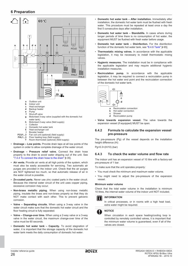
6 Preparation
Installer reference guide
26RRGA04~08DAV3 + RHBX04+08DA
ROTEX HPSU Bi-Bloc Ultra4P495262-1B – 2019.10
M
FCU1FCU2
FCU3
i
M
FHL1FHL2
FHL3
j
l k
fd ecba
f
g h
i
i
i
T
65°C
89°C
a Outdoor unitb Indoor unitc Heat exchangerd Backup heatere Pumpf Shut-off valveg Motorised 3-way valve (supplied with the domestic hot
water tank)h Motorised 2-way valve (field supply)i Collectorj Domestic hot water tank
k Heat exchanger coill Booster heater
FCU1...3 Fan coil unit (optional) (field supply)FHL1...3 Floor heating loop (field supply)
T Room thermostat (optional) (field supply)
▪ Drainage – Low points. Provide drain taps at all low points of thesystem in order to allow complete drainage of the water circuit.
▪ Drainage – Pressure relief valve. Connect the drain hoseproperly to the drain to avoid water dripping out of the unit. See"7.4.4 To connect the drain hose to the drain" [4 35].
▪ Air vents. Provide air vents at all high points of the system, whichmust also be easily accessible for servicing. Two automatic airpurges are provided in the indoor unit. Check that the air purgesare NOT tightened too much, so that automatic release of air inthe water circuit is possible.
▪ Zn-coated parts. Never use zinc coated parts in the water circuit.Because the internal water circuit of the unit uses copper piping,excessive corrosion may occur.
▪ Non-brass metallic piping. When using non-brass metallicpiping, insulate the brass and non-brass properly so that they doNOT make contact with each other. This to prevent galvaniccorrosion.
▪ Valve – Separating circuits. When using a 3-way valve in thewater circuit make sure that the domestic hot water circuit and thefloor heating circuit is fully separated.
▪ Valve – Change‑over time. When using a 2-way valve or a 3-wayvalve in the water circuit, the maximum change-over time of thevalve must be 60 seconds.
▪ Domestic hot water tank – Capacity. To avoid stagnation ofwater, it is important that the storage capacity of the domestic hotwater tank meets the daily consumption of domestic hot water.
▪ Domestic hot water tank – After installation. Immediately afterinstallation, the domestic hot water tank must be flushed with freshwater. This procedure must be repeated at least once a day thefirst 5 consecutive days after installation.
▪ Domestic hot water tank – Standstills. In cases where duringlonger periods of time there is no consumption of hot water, theequipment MUST be flushed with fresh water before usage.
▪ Domestic hot water tank – Disinfection. For the disinfectionfunction of the domestic hot water tank, see "8.4.6 Tank" [4 65].
▪ Thermostatic mixing valves. In accordance with the applicablelegislation, it may be necessary to install thermostatic mixingvalves.
▪ Hygienic measures. The installation must be in compliance withthe applicable legislation and may require additional hygienicinstallation measures.
▪ Recirculation pump. In accordance with the applicablelegislation, it may be required to connect a recirculation pump inbetween the hot water end point and the recirculation connectionof the domestic hot water tank.
cda b
a Recirculation connectionb Hot water connectionc Showerd Recirculation pump
▪ Valve towards expansion vessel. The valve towards theexpansion vessel (if equipped) MUST be open.
6.4.2 Formula to calculate the expansion vesselpre-pressure
The pre-pressure (Pg) of the vessel depends on the installationheight difference (H):
Pg=0.3+(H/10) (bar)
6.4.3 To check the water volume and flow rateThe indoor unit has an expansion vessel of 10 litre with a factory-setpre-pressure of 1 bar.
To make sure that the unit operates properly:
▪ You must check the minimum and maximum water volume.
▪ You might need to adjust the pre-pressure of the expansionvessel.
Minimum water volumeCheck that the total water volume in the installation is minimum10 litres, the internal water volume of the indoor unit NOT included.
INFORMATIONIn critical processes, or in rooms with a high heat load,extra water might be required.
NOTICEWhen circulation in each space heating/cooling loop iscontrolled by remotely controlled valves, it is important thatthe minimum water volume is guaranteed, even if all of thevalves are closed.

6 Preparation
Installer reference guide
27RRGA04~08DAV3 + RHBX04+08DAROTEX HPSU Bi-Bloc Ultra4P495262-1B – 2019.10
FHL1FHL2
FHL3
M1
T1
M2
T2
M3
T3
fdcba
f
g h
e
a Outdoor unitb Indoor unitc Heat exchangerd Backup heatere Pumpf Shut-off valveg Collector (field supply)h Overpressure bypass valve (delivered as accessory)
FHL1...3 Floor heating loop (field supply)T1...3 Individual room thermostat (optional)M1...3 Individual motorised valve to control loop FHL1...3 (field
supply)
Maximum water volumeUse the following graph to determine the maximum water volume forthe calculated pre-pressure.
0.30.5
1
1.5
2
2.4
5020 100 150 200 250 290
a
ba Pre-pressure (bar)b Maximum water volume (l)
Example: Maximum water volume and expansion vessel pre-pressure
Installationheight
difference(a)
Water volume≤200 l >200 l
≤7 m No pre-pressureadjustment is required.
Do the following:
▪ Decrease the pre-pressure according tothe required installationheight difference. Thepre-pressure shoulddecrease by 0.1 bar foreach metre below 7 m.
▪ Check if the watervolume does NOTexceed the maximumallowed water volume.
Installationheight
difference(a)
Water volume≤200 l >200 l
>7 m Do the following:
▪ Increase the pre-pressure according tothe requiredinstallation heightdifference. The pre-pressure shouldincrease by 0.1 bar foreach metre above 7 m.
▪ Check if the watervolume does NOTexceed the maximumallowed water volume.
The expansion vessel ofthe indoor unit is toosmall for the installation.In this case, it isrecommended to installan extra vessel outsidethe unit.
(a) This is the height difference (m) between the highestpoint of the water circuit and the indoor unit. If the indoorunit is at the highest point of the installation, theinstallation height is 0 m.
Minimum flow rateCheck that the minimum flow rate in the installation is guaranteed inall conditions. This minimum flow rate is required during defrost/backup heater operation. For this purpose, use the overpressurebypass valve delivered with the unit, and respect the minimum watervolume.
NOTICEWhen circulation in each or certain space heating loops iscontrolled by remotely controlled valves, it is important thatthe minimum flow rate is guaranteed, even if all valves areclosed. In case the minimum flow rate cannot be reached,a flow error 7H will be generated (no heating or operation).
Minimum required flow rate12 l/min
See the recommended procedure as described in "9.4 Checklistduring commissioning" [4 80].
6.4.4 Changing the pre-pressure of theexpansion vessel
NOTICEOnly a licensed installer may adjust the pre-pressure of theexpansion vessel.
The default pre-pressure of the expansion vessel is 1 bar. When it isrequired to change the pre-pressure, take following guidelines intoaccount:
▪ Only use dry nitrogen to set the expansion vessel pre-pressure.
▪ Inappropriate setting of the expansion vessel pre-pressure willlead to malfunction of the system.
Changing the pre-pressure of the expansion vessel should be doneby releasing or increasing nitrogen pressure through the Schradervalve of the expansion vessel.
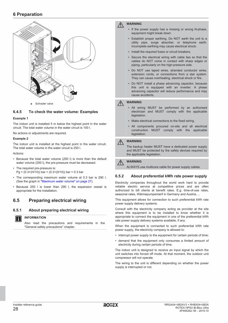
6 Preparation
Installer reference guide
28RRGA04~08DAV3 + RHBX04+08DA
ROTEX HPSU Bi-Bloc Ultra4P495262-1B – 2019.10
a
1
2
3
a Schrader valve
6.4.5 To check the water volume: ExamplesExample 1The indoor unit is installed 5 m below the highest point in the watercircuit. The total water volume in the water circuit is 100 l.
No actions or adjustments are required.
Example 2The indoor unit is installed at the highest point in the water circuit.The total water volume in the water circuit is 250 l.
Actions:
▪ Because the total water volume (250 l) is more than the defaultwater volume (200 l), the pre-pressure must be decreased.
▪ The required pre-pressure is:Pg = (0.3+(H/10)) bar = (0.3+(0/10)) bar = 0.3 bar
▪ The corresponding maximum water volume at 0.3 bar is 290 l.(See the graph in "Maximum water volume" on page 27).
▪ Because 250 l is lower than 290 l, the expansion vessel isappropriate for the installation.
6.5 Preparing electrical wiring
6.5.1 About preparing electrical wiring
INFORMATIONAlso read the precautions and requirements in the"General safety precautions" chapter.
WARNING▪ If the power supply has a missing or wrong N-phase,
equipment might break down.
▪ Establish proper earthing. Do NOT earth the unit to autility pipe, surge absorber, or telephone earth.Incomplete earthing may cause electrical shock.
▪ Install the required fuses or circuit breakers.
▪ Secure the electrical wiring with cable ties so that thecables do NOT come in contact with sharp edges orpiping, particularly on the high-pressure side.
▪ Do NOT use taped wires, stranded conductor wires,extension cords, or connections from a star system.They can cause overheating, electrical shock or fire.
▪ Do NOT install a phase advancing capacitor, becausethis unit is equipped with an inverter. A phaseadvancing capacitor will reduce performance and maycause accidents.
WARNING▪ All wiring MUST be performed by an authorised
electrician and MUST comply with the applicablelegislation.
▪ Make electrical connections to the fixed wiring.
▪ All components procured on-site and all electricalconstruction MUST comply with the applicablelegislation.
WARNINGThe backup heater MUST have a dedicated power supplyand MUST be protected by the safety devices required bythe applicable legislation.
WARNINGALWAYS use multicore cable for power supply cables.
6.5.2 About preferential kWh rate power supplyElectricity companies throughout the world work hard to providereliable electric service at competitive prices and are oftenauthorized to bill clients at benefit rates. E.g. time-of-use rates,seasonal rates, Wärmepumpentarif in Germany and Austria, ...
This equipment allows for connection to such preferential kWh ratepower supply delivery systems.
Consult with the electricity company acting as provider at the sitewhere this equipment is to be installed to know whether it isappropriate to connect the equipment in one of the preferential kWhrate power supply delivery systems available, if any.
When the equipment is connected to such preferential kWh ratepower supply, the electricity company is allowed to:
▪ interrupt power supply to the equipment for certain periods of time;
▪ demand that the equipment only consumes a limited amount ofelectricity during certain periods of time.
The indoor unit is designed to receive an input signal by which theunit switches into forced off mode. At that moment, the outdoor unitcompressor will not operate.
The wiring to the unit is different depending on whether the powersupply is interrupted or not.
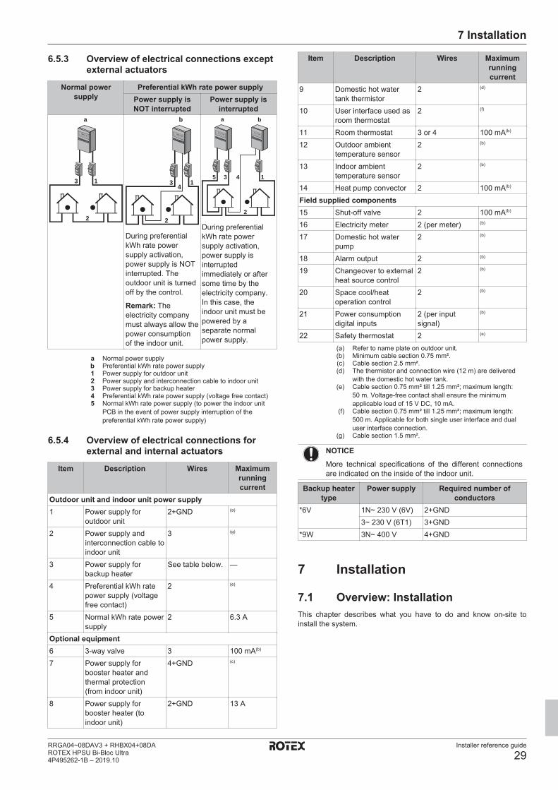
7 Installation
Installer reference guide
29RRGA04~08DAV3 + RHBX04+08DAROTEX HPSU Bi-Bloc Ultra4P495262-1B – 2019.10
6.5.3 Overview of electrical connections exceptexternal actuators
Normal powersupply
Preferential kWh rate power supplyPower supply isNOT interrupted
Power supply isinterrupted
1
5801 5000
2
a
3 14
5801 5000
2
b
3
During preferentialkWh rate powersupply activation,power supply is NOTinterrupted. Theoutdoor unit is turnedoff by the control.
Remark: Theelectricity companymust always allow thepower consumptionof the indoor unit.
5 3
a b
14
5801 5000 5801 50
00
2
During preferentialkWh rate powersupply activation,power supply isinterruptedimmediately or aftersome time by theelectricity company.In this case, theindoor unit must bepowered by aseparate normalpower supply.
a Normal power supplyb Preferential kWh rate power supply1 Power supply for outdoor unit2 Power supply and interconnection cable to indoor unit3 Power supply for backup heater4 Preferential kWh rate power supply (voltage free contact)5 Normal kWh rate power supply (to power the indoor unit
PCB in the event of power supply interruption of thepreferential kWh rate power supply)
6.5.4 Overview of electrical connections forexternal and internal actuators
Item Description Wires Maximumrunningcurrent
Outdoor unit and indoor unit power supply1 Power supply for
outdoor unit2+GND (a)
2 Power supply andinterconnection cable toindoor unit
3 (g)
3 Power supply forbackup heater
See table below. —
4 Preferential kWh ratepower supply (voltagefree contact)
2 (e)
5 Normal kWh rate powersupply
2 6.3 A
Optional equipment6 3‑way valve 3 100 mA(b)
7 Power supply forbooster heater andthermal protection(from indoor unit)
4+GND (c)
8 Power supply forbooster heater (toindoor unit)
2+GND 13 A
Item Description Wires Maximumrunningcurrent
9 Domestic hot watertank thermistor
2 (d)
10 User interface used asroom thermostat
2 (f)
11 Room thermostat 3 or 4 100 mA(b)
12 Outdoor ambienttemperature sensor
2 (b)
13 Indoor ambienttemperature sensor
2 (b)
14 Heat pump convector 2 100 mA(b)
Field supplied components15 Shut-off valve 2 100 mA(b)
16 Electricity meter 2 (per meter) (b)
17 Domestic hot waterpump
2 (b)
18 Alarm output 2 (b)
19 Changeover to externalheat source control
2 (b)
20 Space cool/heatoperation control
2 (b)
21 Power consumptiondigital inputs
2 (per inputsignal)
(b)
22 Safety thermostat 2 (e)
(a) Refer to name plate on outdoor unit.(b) Minimum cable section 0.75 mm².(c) Cable section 2.5 mm².(d) The thermistor and connection wire (12 m) are delivered
with the domestic hot water tank.(e) Cable section 0.75 mm² till 1.25 mm²; maximum length:
50 m. Voltage-free contact shall ensure the minimumapplicable load of 15 V DC, 10 mA.
(f) Cable section 0.75 mm² till 1.25 mm²; maximum length:500 m. Applicable for both single user interface and dualuser interface connection.
(g) Cable section 1.5 mm².
NOTICEMore technical specifications of the different connectionsare indicated on the inside of the indoor unit.
Backup heatertype
Power supply Required number ofconductors
*6V 1N~ 230 V (6V) 2+GND3~ 230 V (6T1) 3+GND
*9W 3N~ 400 V 4+GND
7 Installation
7.1 Overview: InstallationThis chapter describes what you have to do and know on-site toinstall the system.
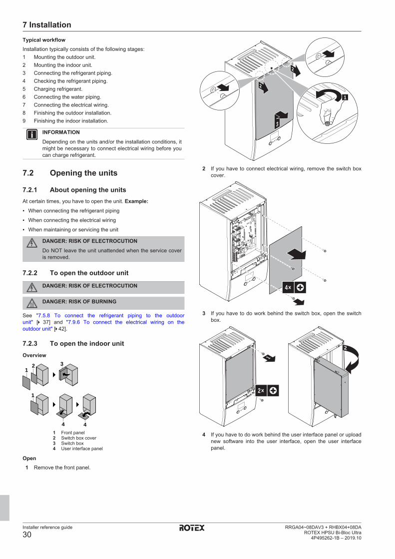
7 Installation
Installer reference guide
30RRGA04~08DAV3 + RHBX04+08DA
ROTEX HPSU Bi-Bloc Ultra4P495262-1B – 2019.10
Typical workflowInstallation typically consists of the following stages:1 Mounting the outdoor unit.2 Mounting the indoor unit.3 Connecting the refrigerant piping.4 Checking the refrigerant piping.5 Charging refrigerant.6 Connecting the water piping.7 Connecting the electrical wiring.8 Finishing the outdoor installation.9 Finishing the indoor installation.
INFORMATIONDepending on the units and/or the installation conditions, itmight be necessary to connect electrical wiring before youcan charge refrigerant.
7.2 Opening the units
7.2.1 About opening the unitsAt certain times, you have to open the unit. Example:▪ When connecting the refrigerant piping
▪ When connecting the electrical wiring
▪ When maintaining or servicing the unit
DANGER: RISK OF ELECTROCUTIONDo NOT leave the unit unattended when the service coveris removed.
7.2.2 To open the outdoor unit
DANGER: RISK OF ELECTROCUTION
DANGER: RISK OF BURNING
See "7.5.8 To connect the refrigerant piping to the outdoorunit" [4 37] and "7.9.6 To connect the electrical wiring on theoutdoor unit" [4 42].
7.2.3 To open the indoor unitOverview
12 3
1
4 41 Front panel2 Switch box cover3 Switch box4 User interface panel
Open1 Remove the front panel.
2
2
1
3
2 If you have to connect electrical wiring, remove the switch boxcover.
4×
3 If you have to do work behind the switch box, open the switchbox.
2×
1
2
4 If you have to do work behind the user interface panel or uploadnew software into the user interface, open the user interfacepanel.

7 Installation
Installer reference guide
31RRGA04~08DAV3 + RHBX04+08DAROTEX HPSU Bi-Bloc Ultra4P495262-1B – 2019.10
12
3
2×
5 Optional: Remove the user interface panel.
NOTICEIf you remove the user interface panel, also disconnect thecables from the back of the user interface panel to preventdamage.
31
2
7.3 Mounting the outdoor unit
7.3.1 About mounting the outdoor unitWhenYou have to mount the outdoor and indoor unit before you canconnect the refrigerant and water piping.
Typical workflowMounting the outdoor unit typically consists of the following stages:1 Providing the installation structure.2 Installing the outdoor unit.3 Providing drainage.4 Preventing the unit from falling over.5 Protecting the unit against snow and wind by installing a snow
cover and baffle plates. See "Preparing installation site" in"6 Preparation" [4 21].
7.3.2 Precautions when mounting the outdoorunit
INFORMATIONAlso read the precautions and requirements in thefollowing chapters:
▪ General safety precautions
▪ Preparation
7.3.3 To provide the installation structureCheck the strength and level of the installation ground so that theunit will not cause any operating vibration or noise.
Fix the unit securely by means of foundation bolts in accordancewith the foundation drawing.
This topic shows different installation structures. For all, use 4 setsof M8 or M10 anchor bolts, nuts and washers. In any case, provideat least 300 mm of free space below the unit. Additionally, makesure the unit is positioned at least 100 mm above the maximumexpected level of snow.
INFORMATIONThe maximum height of the upper protruding part of thebolts is 15 mm.
INFORMATIONIf you install the U-beams in combination with the lowsound cover (EKLN08A1), different installation instructionsapply for the U-beams. See the installation manual of thelow sound cover.
a
b
c
a Low sound cover
b Bottom parts of the low sound cover
c U-beams
Option 1: On mounting feet "flexi-foot with strut"
(mm)
0 mm
<150a
>300
300600 >1
00
a Maximum snowfall height
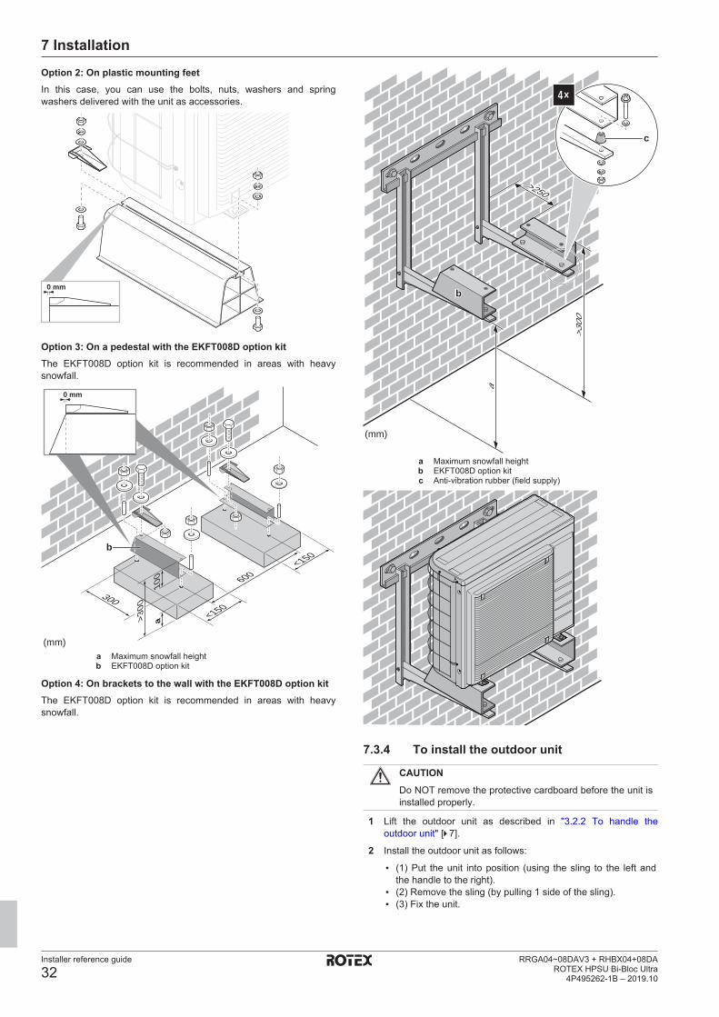
7 Installation
Installer reference guide
32RRGA04~08DAV3 + RHBX04+08DA
ROTEX HPSU Bi-Bloc Ultra4P495262-1B – 2019.10
Option 2: On plastic mounting feetIn this case, you can use the bolts, nuts, washers and springwashers delivered with the unit as accessories.
0 mm
Option 3: On a pedestal with the EKFT008D option kitThe EKFT008D option kit is recommended in areas with heavysnowfall.
300
600
<150
<150
(mm)
>300
100
a
b
0 mm
a Maximum snowfall heightb EKFT008D option kit
Option 4: On brackets to the wall with the EKFT008D option kitThe EKFT008D option kit is recommended in areas with heavysnowfall.
>250
>300
>250
(mm)
a
b
c
4×
a Maximum snowfall heightb EKFT008D option kitc Anti-vibration rubber (field supply)
7.3.4 To install the outdoor unit
CAUTIONDo NOT remove the protective cardboard before the unit isinstalled properly.
1 Lift the outdoor unit as described in "3.2.2 To handle theoutdoor unit" [4 7].
2 Install the outdoor unit as follows:
▪ (1) Put the unit into position (using the sling to the left andthe handle to the right).
▪ (2) Remove the sling (by pulling 1 side of the sling).▪ (3) Fix the unit.

7 Installation
Installer reference guide
33RRGA04~08DAV3 + RHBX04+08DAROTEX HPSU Bi-Bloc Ultra4P495262-1B – 2019.10
2×
3
2
1
a a
a Air outlet
NOTICEProperly align the unit. Make sure the backside of the unitdoes NOT protrude.
3 Remove the protective cardboard and instruction sheet.
a
b
a Protective cardboardb Instruction sheet
7.3.5 To provide drainage▪ Make sure that condensation water can be evacuated properly.
▪ Install the unit on a base to make sure that there is properdrainage in order to avoid ice accumulation.
▪ Prepare a water drainage channel around the foundation to drainwaste water away from the unit.
▪ Avoid drain water flowing over the footpath, so that it does NOTbecome slippery in case of ambient freezing temperatures.
▪ If you install the unit on a frame, install a waterproof plate within150 mm of the bottom side of the unit in order to prevent waterfrom getting into the unit and to avoid drain water dripping (see thefollowing figure).
NOTICEIf the drain holes of the outdoor unit are blocked up,provide space of at least 300 mm below the outdoor unit.
▪ Drain pan. You can use the drain pan option (EKDP008D) togather the drain water. For the complete installation instructions,see the installation manual of the drain pan. In short, the drain panmust be installed level (with a tolerance of 1° at all sides) and asfollows:
b
a
c
a Drain panb U-beamsc Drain hole insulation
355 mm
600 mm
▪ Drain pan heater. You can use the drain pan heater option(EKDPH008CA) to prevent freezing-up of the drain pan. For theinstallation instructions, see the installation manual of the drainpan heater.
▪ Non-heated drain tube. When using the drain pan heater withoutdrain tube or with a non-heated drain tube, remove the drain holeinsulation (Item c on the illustration).

7 Installation
Installer reference guide
34RRGA04~08DAV3 + RHBX04+08DA
ROTEX HPSU Bi-Bloc Ultra4P495262-1B – 2019.10
INFORMATIONIf you install the drain pan kit (with or without drain panheater) in combination with the low sound cover(EKLN08A1), different installation instructions apply for thedrain pan kit. See the installation manual of the low soundcover.
a b
dc
c
b
a Low sound cover
b Bottom parts of the low sound cover
c Drain pan kit
d Drain pan heater
7.3.6 To prevent the outdoor unit from fallingover
In case the unit is installed in places where strong wind can tilt theunit, take following measure:
1 Prepare 2 cables as indicated in the following illustration (fieldsupply).
2 Place the 2 cables over the outdoor unit.
3 Insert a rubber sheet between the cables and the outdoor unitto prevent the cables from scratching the paint (field supply).
4 Attach the ends of the cables and tighten them.
7.4 Mounting the indoor unit
7.4.1 About mounting the indoor unitWhenYou have to mount the outdoor and indoor unit before you canconnect the refrigerant and water piping.
Typical workflowMounting the indoor unit typically consists of the following stages:1 Installing the indoor unit.
7.4.2 Precautions when mounting the indoorunit
INFORMATIONAlso read the precautions and requirements in thefollowing chapters:
▪ General safety precautions
▪ Preparation
7.4.3 To install the indoor unit1 Fix the wall bracket (accessory) to the wall (level) with 2 Ø8 mm
bolts.
2×
a
a Optional: If you want to fix the unit to the wall from insidethe unit, provide an additional screw plug.
2 Lift the unit.
42 kg
3 Attach the unit to the wall bracket:
▪ Tilt the top of the unit against the wall at the position of thewall bracket.
▪ Slide the bracket on the back of the unit over the wallbracket. Make sure the unit is fixed properly.
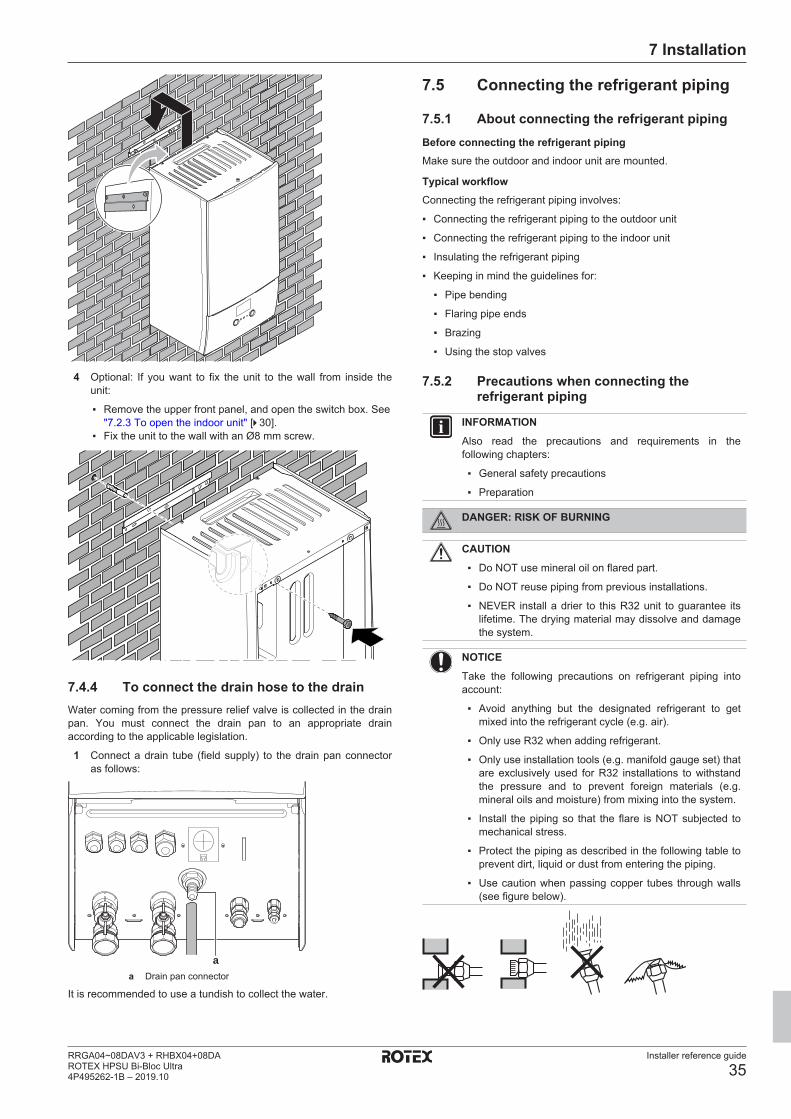
7 Installation
Installer reference guide
35RRGA04~08DAV3 + RHBX04+08DAROTEX HPSU Bi-Bloc Ultra4P495262-1B – 2019.10
4 Optional: If you want to fix the unit to the wall from inside theunit:
▪ Remove the upper front panel, and open the switch box. See"7.2.3 To open the indoor unit" [4 30].
▪ Fix the unit to the wall with an Ø8 mm screw.
7.4.4 To connect the drain hose to the drainWater coming from the pressure relief valve is collected in the drainpan. You must connect the drain pan to an appropriate drainaccording to the applicable legislation.
1 Connect a drain tube (field supply) to the drain pan connectoras follows:
aa Drain pan connector
It is recommended to use a tundish to collect the water.
7.5 Connecting the refrigerant piping
7.5.1 About connecting the refrigerant pipingBefore connecting the refrigerant pipingMake sure the outdoor and indoor unit are mounted.
Typical workflowConnecting the refrigerant piping involves:
▪ Connecting the refrigerant piping to the outdoor unit
▪ Connecting the refrigerant piping to the indoor unit
▪ Insulating the refrigerant piping
▪ Keeping in mind the guidelines for:
▪ Pipe bending
▪ Flaring pipe ends
▪ Brazing
▪ Using the stop valves
7.5.2 Precautions when connecting therefrigerant piping
INFORMATIONAlso read the precautions and requirements in thefollowing chapters:
▪ General safety precautions
▪ Preparation
DANGER: RISK OF BURNING
CAUTION▪ Do NOT use mineral oil on flared part.
▪ Do NOT reuse piping from previous installations.
▪ NEVER install a drier to this R32 unit to guarantee itslifetime. The drying material may dissolve and damagethe system.
NOTICETake the following precautions on refrigerant piping intoaccount:
▪ Avoid anything but the designated refrigerant to getmixed into the refrigerant cycle (e.g. air).
▪ Only use R32 when adding refrigerant.
▪ Only use installation tools (e.g. manifold gauge set) thatare exclusively used for R32 installations to withstandthe pressure and to prevent foreign materials (e.g.mineral oils and moisture) from mixing into the system.
▪ Install the piping so that the flare is NOT subjected tomechanical stress.
▪ Protect the piping as described in the following table toprevent dirt, liquid or dust from entering the piping.
▪ Use caution when passing copper tubes through walls(see figure below).
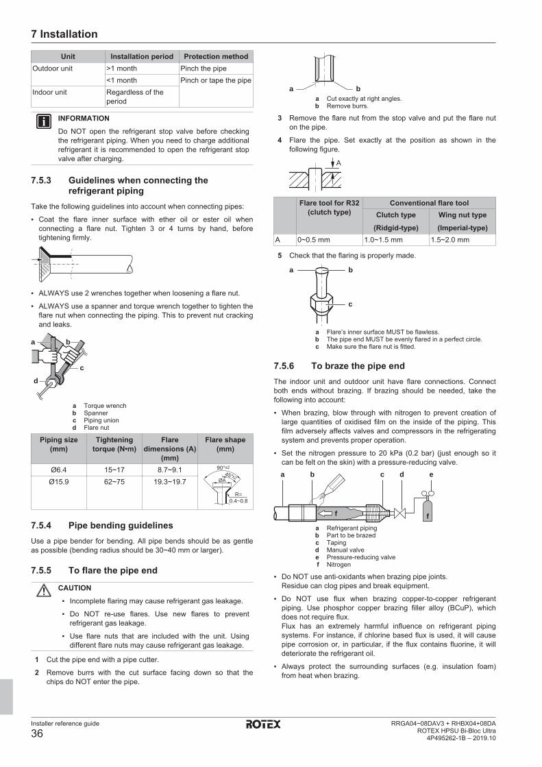
7 Installation
Installer reference guide
36RRGA04~08DAV3 + RHBX04+08DA
ROTEX HPSU Bi-Bloc Ultra4P495262-1B – 2019.10
Unit Installation period Protection methodOutdoor unit >1 month Pinch the pipe
<1 month Pinch or tape the pipeIndoor unit Regardless of the
period
INFORMATIONDo NOT open the refrigerant stop valve before checkingthe refrigerant piping. When you need to charge additionalrefrigerant it is recommended to open the refrigerant stopvalve after charging.
7.5.3 Guidelines when connecting therefrigerant piping
Take the following guidelines into account when connecting pipes:
▪ Coat the flare inner surface with ether oil or ester oil whenconnecting a flare nut. Tighten 3 or 4 turns by hand, beforetightening firmly.
▪ ALWAYS use 2 wrenches together when loosening a flare nut.
▪ ALWAYS use a spanner and torque wrench together to tighten theflare nut when connecting the piping. This to prevent nut crackingand leaks.
a b
c
d
a Torque wrenchb Spannerc Piping uniond Flare nut
Piping size(mm)
Tighteningtorque (N•m)
Flaredimensions (A)
(mm)
Flare shape(mm)
Ø6.4 15~17 8.7~9.1
R=0.4~0.8
±245°
90°±2
ØAØ15.9 62~75 19.3~19.7
7.5.4 Pipe bending guidelinesUse a pipe bender for bending. All pipe bends should be as gentleas possible (bending radius should be 30~40 mm or larger).
7.5.5 To flare the pipe end
CAUTION▪ Incomplete flaring may cause refrigerant gas leakage.
▪ Do NOT re-use flares. Use new flares to preventrefrigerant gas leakage.
▪ Use flare nuts that are included with the unit. Usingdifferent flare nuts may cause refrigerant gas leakage.
1 Cut the pipe end with a pipe cutter.
2 Remove burrs with the cut surface facing down so that thechips do NOT enter the pipe.
a ba Cut exactly at right angles.b Remove burrs.
3 Remove the flare nut from the stop valve and put the flare nuton the pipe.
4 Flare the pipe. Set exactly at the position as shown in thefollowing figure.
A
Flare tool for R32(clutch type)
Conventional flare toolClutch type
(Ridgid-type)Wing nut type(Imperial-type)
A 0~0.5 mm 1.0~1.5 mm 1.5~2.0 mm
5 Check that the flaring is properly made.
a b
c
a Flare’s inner surface MUST be flawless.b The pipe end MUST be evenly flared in a perfect circle.c Make sure the flare nut is fitted.
7.5.6 To braze the pipe endThe indoor unit and outdoor unit have flare connections. Connectboth ends without brazing. If brazing should be needed, take thefollowing into account:
▪ When brazing, blow through with nitrogen to prevent creation oflarge quantities of oxidised film on the inside of the piping. Thisfilm adversely affects valves and compressors in the refrigeratingsystem and prevents proper operation.
▪ Set the nitrogen pressure to 20 kPa (0.2 bar) (just enough so itcan be felt on the skin) with a pressure-reducing valve.a b c d e
ff
a Refrigerant pipingb Part to be brazedc Tapingd Manual valvee Pressure-reducing valvef Nitrogen
▪ Do NOT use anti-oxidants when brazing pipe joints.Residue can clog pipes and break equipment.
▪ Do NOT use flux when brazing copper-to-copper refrigerantpiping. Use phosphor copper brazing filler alloy (BCuP), whichdoes not require flux.Flux has an extremely harmful influence on refrigerant pipingsystems. For instance, if chlorine based flux is used, it will causepipe corrosion or, in particular, if the flux contains fluorine, it willdeteriorate the refrigerant oil.
▪ Always protect the surrounding surfaces (e.g. insulation foam)from heat when brazing.
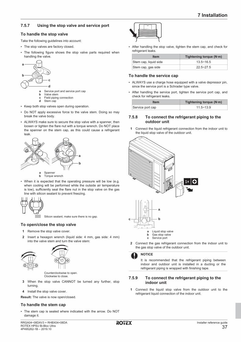
7 Installation
Installer reference guide
37RRGA04~08DAV3 + RHBX04+08DAROTEX HPSU Bi-Bloc Ultra4P495262-1B – 2019.10
7.5.7 Using the stop valve and service port
To handle the stop valveTake the following guidelines into account:
▪ The stop valves are factory closed.
▪ The following figure shows the stop valve parts required whenhandling the valve.
c
d
a
b
a Service port and service port capb Valve stemc Field piping connectiond Stem cap
▪ Keep both stop valves open during operation.
▪ Do NOT apply excessive force to the valve stem. Doing so maybreak the valve body.
▪ ALWAYS make sure to secure the stop valve with a spanner, thenloosen or tighten the flare nut with a torque wrench. Do NOT placethe spanner on the stem cap, as this could cause a refrigerantleak.
a
b
a Spannerb Torque wrench
▪ When it is expected that the operating pressure will be low (e.g.when cooling will be performed while the outside air temperatureis low), sufficiently seal the flare nut in the stop valve on the gasline with silicon sealant to prevent freezing.
Silicon sealant; make sure there is no gap.
To open/close the stop valve1 Remove the stop valve cover.
2 Insert a hexagon wrench (liquid side: 4 mm, gas side: 4 mm)into the valve stem and turn the valve stem:
Counterclockwise to open.Clockwise to close.
3 When the stop valve CANNOT be turned any further, stopturning.
4 Install the stop valve cover.
Result: The valve is now open/closed.
To handle the stem cap▪ The stem cap is sealed where indicated with the arrow. Do NOT
damage it.
▪ After handling the stop valve, tighten the stem cap, and check forrefrigerant leaks.
Item Tightening torque (N∙m)Stem cap, liquid side 13.5~16.5Stem cap, gas side 22.5~27.5
To handle the service cap▪ ALWAYS use a charge hose equipped with a valve depressor pin,
since the service port is a Schrader type valve.
▪ After handling the service port, tighten the service port cap, andcheck for refrigerant leaks.
Item Tightening torque (N∙m)Service port cap 11.5~13.9
7.5.8 To connect the refrigerant piping to theoutdoor unit
1 Connect the liquid refrigerant connection from the indoor unit tothe liquid stop valve of the outdoor unit.
1×
a
bc
a Liquid stop valveb Gas stop valvec Service port
2 Connect the gas refrigerant connection from the indoor unit tothe gas stop valve of the outdoor unit.
NOTICEIt is recommended that the refrigerant piping betweenindoor and outdoor unit is installed in a ducting or therefrigerant piping is wrapped with finishing tape.
7.5.9 To connect the refrigerant piping to theindoor unit
1 Connect the liquid stop valve from the outdoor unit to therefrigerant liquid connection of the indoor unit.

7 Installation
Installer reference guide
38RRGA04~08DAV3 + RHBX04+08DA
ROTEX HPSU Bi-Bloc Ultra4P495262-1B – 2019.10
aba Refrigerant liquid connectionb Refrigerant gas connection
2 Connect the gas stop valve from the outdoor unit to therefrigerant gas connection of the indoor unit.
NOTICEIt is recommended that the refrigerant piping betweenindoor and outdoor unit is installed in a ducting or therefrigerant piping is wrapped with finishing tape.
7.6 Checking the refrigerant piping
7.6.1 About checking the refrigerant pipingThe outdoor unit's internal refrigerant piping has been factory testedfor leaks. You only have to check the outdoor unit's externalrefrigerant piping.
Before checking the refrigerant pipingMake sure the refrigerant piping is connected between the outdoorunit and the indoor unit.
Typical workflowChecking the refrigerant piping typically consists of the followingstages:1 Checking for leaks in the refrigerant piping.2 Performing vacuum drying to remove all moisture, air or
nitrogen from the refrigerant piping.
If there is a possibility of moisture being present in the refrigerantpiping (for example, water may have entered the piping), first carryout the vacuum drying procedure below until all moisture has beenremoved.
7.6.2 Precautions when checking therefrigerant piping
INFORMATIONAlso read the precautions and requirements in thefollowing chapters:
▪ General safety precautions
▪ Preparation
NOTICEUse a 2-stage vacuum pump with a non-return valve thatcan evacuate to a gauge pressure of −100.7 kPa(−1.007 bar)(5 Torr absolute). Make sure the pump oildoes not flow oppositely into the system while the pump isnot working.
NOTICEUse this vacuum pump for R32 exclusively. Using thesame pump for other refrigerants may damage the pumpand the unit.
NOTICE▪ Connect the vacuum pump to the service port of the
gas stop valve.
▪ Make sure that the gas stop valve and liquid stop valveare firmly closed before performing the leak test orvacuum drying.
7.6.3 To check for leaks
NOTICEDo NOT exceed the unit's maximum working pressure (see"PS High" on the unit name plate).
NOTICEMake sure to use a recommended bubble test solutionfrom your wholesaler. Do not use soap water, which maycause cracking of flare nuts (soap water may contain salt,which absorbs moisture that will freeze when the pipinggets cold), and/or lead to corrosion of flared joints (soapwater may contain ammonia which causes a corrosiveeffect between the brass flare nut and the copper flare).
1 Charge the system with nitrogen gas up to a gauge pressure ofat least 200 kPa (2 bar). It is recommended to pressurize to3000 kPa (30 bar) in order to detect small leaks.
2 Check for leaks by applying the bubble test solution to allconnections.
3 Discharge all nitrogen gas.
7.6.4 To perform vacuum dryingConnect the vacuum pump and manifold as follows:
a d
j
b
f
e
c
g h i
h
a Pressure meterb Gauge manifoldc Low-pressure valve (Lo)d High-pressure valve (Hi)e Charging hosesf Vacuum pumpg Service porth Valve lidsi Gas stop valvej Liquid stop valve
1 Vacuum the system until the pressure on the manifold indicates−0.1 MPa (−1 bar).
2 Leave as is for 4-5 minutes and check the pressure:
If the pressure… Then…Does not change There is no moisture in the
system. This procedure isfinished.
Increases There is moisture in thesystem. Go to the next step.
3 Vacuum the system for at least 2 hours to a manifold pressureof −0.1 MPa (−1 bar).
4 After turning the pump OFF, check the pressure for at least1 hour.
7 Installation
Installer reference guide
39RRGA04~08DAV3 + RHBX04+08DAROTEX HPSU Bi-Bloc Ultra4P495262-1B – 2019.10
5 If you do NOT reach the target vacuum or CANNOT maintainthe vacuum for 1 hour, do the following:
▪ Check for leaks again.▪ Perform vacuum drying again.
NOTICEMake sure to open the stop valves after installing therefrigerant piping and performing vacuum drying. Runningthe system with the stop valves closed may break thecompressor.
INFORMATIONAfter opening the stop valve, it is possible that the pressurein the refrigerant piping does NOT increase. This might becaused by e.g. the closed state of the expansion valve inthe outdoor unit circuit, but does NOT present any problemfor correct operation of the unit.
7.7 Charging refrigerant
7.7.1 About charging refrigerantThe outdoor unit is factory charged with refrigerant, but in somecases the following might be necessary:
What WhenCharging additional refrigerant When the total liquid piping
length is more than specified(see later).
Completely recharging refrigerant Example: ▪ When relocating the system.
▪ After a leak.
Charging additional refrigerantBefore charging additional refrigerant, make sure the outdoor unit'sexternal refrigerant piping is checked (leak test, vacuum drying).
INFORMATIONDepending on the units and/or the installation conditions, itmight be necessary to connect electrical wiring before youcan charge refrigerant.
Typical workflow – Charging additional refrigerant typically consistsof the following stages:
1 Determining if and how much you have to charge additionally.2 If necessary, charging additional refrigerant.3 Filling in the fluorinated greenhouse gases label, and fixing it to
the inside of the outdoor unit.
Completely recharging refrigerantBefore completely recharging refrigerant, make sure the following isdone:
1 All refrigerant is recovered from the system.2 The outdoor unit's external refrigerant piping is checked (leak
test, vacuum drying).3 Vacuum drying on the outdoor unit's internal refrigerant piping is
performed.
NOTICEBefore completely recharging, perform vacuum drying onthe outdoor unit's internal refrigerant piping as well.
Typical workflow – Completely recharging refrigerant typicallyconsists of the following stages:
1 Determining how much refrigerant to charge.2 Charging refrigerant.
3 Filling in the fluorinated greenhouse gases label, and fixing it tothe inside of the outdoor unit.
7.7.2 Precautions when charging refrigerant
INFORMATIONAlso read the precautions and requirements in thefollowing chapters:
▪ General safety precautions
▪ Preparation
7.7.3 To determine the additional refrigerantamount
WARNINGIf the total refrigerant charge in the system is ≥1.84 kg(i.e. if the piping length is ≥27 m), you need to complywith the minimum floor area requirements for the indoorunit. For more information, see "6.2.3 Installation siterequirements of the indoor unit" [4 23].
If the total liquidpiping length is…
Then…
≤10 m Do NOT add additional refrigerant.>10 m R=(total length (m) of liquid
piping–10 m)×0.020
R=Additional charge (kg) (rounded in unitsof 0.01 kg)
INFORMATIONPiping length is the one-way length of liquid piping.
7.7.4 To determine the complete rechargeamount
INFORMATIONIf a complete recharge is necessary, the total refrigerantcharge is: the factory refrigerant charge (see unit nameplate) + the determined additional amount.
7.7.5 To charge additional refrigerant
WARNING▪ Only use R32 as refrigerant. Other substances may
cause explosions and accidents.
▪ R32 contains fluorinated greenhouse gases. Its globalwarming potential (GWP) value is 675. Do NOT ventthese gases into the atmosphere.
▪ When charging refrigerant, ALWAYS use protectivegloves and safety glasses.
CAUTIONTo avoid compressor breakdown, do NOT charge morethan the specified amount of refrigerant.
Prerequisite: Before charging refrigerant, make sure the refrigerantpiping is connected and checked (leak test and vacuum drying).
1 Connect the refrigerant cylinder to the service port.
2 Charge the additional refrigerant amount.
3 Open the gas stop valve.
If pump down is needed in case of dismantling or relocating thesystem, see "13.2 To pump down" [4 91] for more details.
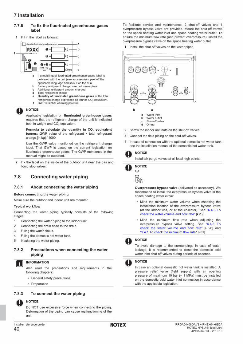
7 Installation
Installer reference guide
40RRGA04~08DAV3 + RHBX04+08DA
ROTEX HPSU Bi-Bloc Ultra4P495262-1B – 2019.10
7.7.6 To fix the fluorinated greenhouse gaseslabel
1 Fill in the label as follows:
bContains fluorinated greenhouse gases
21 1
1
2
2 kgtCO2eq
GWP × kg1000
==
+
kg=
kg=GWP: XXX
RXXXa
fc
de
a If a multilingual fluorinated greenhouse gases label isdelivered with the unit (see accessories), peel off theapplicable language and stick it on top of a.
b Factory refrigerant charge: see unit name platec Additional refrigerant amount chargedd Total refrigerant chargee Quantity of fluorinated greenhouse gases of the total
refrigerant charge expressed as tonnes CO2 equivalent.f GWP = Global warming potential
NOTICEApplicable legislation on fluorinated greenhouse gasesrequires that the refrigerant charge of the unit is indicatedboth in weight and CO2 equivalent.
Formula to calculate the quantity in CO2 equivalenttonnes: GWP value of the refrigerant × total refrigerantcharge [in kg] / 1000
Use the GWP value mentioned on the refrigerant chargelabel. That GWP is based on the current legislation onfluorinated greenhouse gases. The GWP mentioned in themanual might be outdated.
2 Fix the label on the inside of the outdoor unit near the gas andliquid stop valves.
7.8 Connecting water piping
7.8.1 About connecting the water pipingBefore connecting the water pipingMake sure the outdoor and indoor unit are mounted.
Typical workflowConnecting the water piping typically consists of the followingstages:1 Connecting the water piping to the indoor unit.2 Connecting the drain hose to the drain.3 Filling the water circuit.4 Filling the domestic hot water tank.5 Insulating the water piping.
7.8.2 Precautions when connecting the waterpiping
INFORMATIONAlso read the precautions and requirements in thefollowing chapters:
▪ General safety precautions
▪ Preparation
7.8.3 To connect the water piping
NOTICEDo NOT use excessive force when connecting the piping.Deformation of the piping can cause malfunctioning of theunit.
To facilitate service and maintenance, 2 shut-off valves and 1overpressure bypass valve are provided. Mount the shut-off valveson the space heating water inlet and space heating water outlet. Toensure the minimum flow rate (and prevent overpressure), install theoverpressure bypass valve on the space heating water outlet.
1 Install the shut-off valves on the water pipes.
aba Water inletb Water outletc Shut-off valved O-ring
2 Screw the indoor unit nuts on the shut-off valves.
3 Connect the field piping on the shut-off valves.
4 In case of connection with the optional domestic hot water tank,see the installation manual of the domestic hot water tank.
NOTICEInstall air purge valves at all local high points.
NOTICE
Overpressure bypass valve (delivered as accessory). Werecommend to install the overpressure bypass valve in thespace heating water circuit.
▪ Mind the minimum water volume when choosing theinstallation location of the overpressure bypass valve(at the indoor unit, or at the collector). See "6.4.3 Tocheck the water volume and flow rate" [4 26].
▪ Mind the minimum flow rate when adjusting theoverpressure bypass valve setting. See "6.4.3 Tocheck the water volume and flow rate" [4 26] and"9.4.1 To check the minimum flow rate" [4 81].
NOTICETo avoid damage to the surroundings in case of waterleakage, it is recommended to close the domestic coldwater inlet shut‑off valves during periods of absence.
NOTICEIn case an optional domestic hot water tank is installed: Apressure relief valve (field supply) with an openingpressure of maximum 10 bar (= 1 MPa) must be installedon the domestic cold water inlet connection in accordancewith the applicable legislation.
7 Installation
Installer reference guide
41RRGA04~08DAV3 + RHBX04+08DAROTEX HPSU Bi-Bloc Ultra4P495262-1B – 2019.10
NOTICEIn case an optional domestic hot water tank is installed:
▪ A drain device and pressure relief device must beinstalled on the cold water inlet connection of thedomestic hot water cylinder.
▪ To avoid back siphonage, it is recommended to install anon-return valve on the water inlet of the domestic hotwater tank in accordance with the applicable legislation.
▪ It is recommended to install a pressure reducing valveon the cold water inlet in accordance with theapplicable legislation.
▪ An expansion vessel should be installed on the coldwater inlet in accordance with the applicable legislation.
▪ It is recommended to install the pressure relief valve ona higher position than the top of the domestic hot watertank. Heating of the domestic hot water tank causeswater to expand and without pressure relief valve thewater pressure inside the tank can rise above the tankdesign pressure. Also the field installation (piping,tapping points, etc.) connected to the tank is subjectedto this high pressure. To prevent this, a pressure reliefvalve needs to be installed. The overpressureprevention depends on the correct operation of the fieldinstalled pressure relief valve. If this is NOT workingcorrectly, overpressure will deform the tank and waterleakage may occur. To confirm good operation, regularmaintenance is required.
7.8.4 To fill the water circuitTo fill the water circuit, use a field supply filling kit. Make sure youcomply with the applicable legislation.
INFORMATIONMake sure both air purge valves (one on the magnetic filterand one on the backup heater) are open.
7.8.5 To fill the domestic hot water tankSee the installation manual of the domestic hot water tank.
7.8.6 To insulate the water pipingThe piping in the complete water circuit MUST be insulated toprevent condensation during cooling operation and reduction of theheating and cooling capacity.
If the temperature is higher than 30°C and the humidity is higherthan RH 80%, the thickness of the insulation materials should be atleast 20 mm to prevent condensation on the surface of theinsulation.
7.9 Connecting the electrical wiring
7.9.1 About connecting the electrical wiringBefore connecting the electrical wiringMake sure:
▪ The refrigerant piping is connected and checked
▪ The water piping is connected
Typical workflowConnecting the electrical wiring typically consists of the followingstages:1 Making sure the power supply system complies with the
electrical specifications of the heat pump.2 Connecting the electrical wiring to the outdoor unit.3 Connecting the electrical wiring to the indoor unit.4 Connecting the main power supply.5 Connecting the backup heater power supply.6 Connecting the shut-off valves.7 Connecting the electrical meters.8 Connecting the domestic hot water pump.9 Connecting the alarm output.10 Connecting the space cooling/heating ON/OFF output.11 Connecting the changeover to an external heat source.12 Connecting the power consumption digital inputs.13 Connecting the safety thermostat.
7.9.2 About electrical complianceOnly for RRGA04~08DAV3Equipment complying with EN/IEC 61000‑3‑12 (European/International Technical Standard setting the limits for harmoniccurrents produced by equipment connected to public low-voltagesystems with input current >16 A and ≤75 A per phase.).
Only for the backup heater of the indoor unitSee "7.9.9 To connect the backup heater power supply" [4 44].
7.9.3 Precautions when connecting theelectrical wiring
INFORMATIONAlso read the precautions and requirements in thefollowing chapters:
▪ General safety precautions
▪ Preparation
DANGER: RISK OF ELECTROCUTION
WARNINGALWAYS use multicore cable for power supply cables.
7.9.4 Guidelines when connecting the electricalwiring
Keep the following in mind:
▪ If stranded conductor wires are used, install a round crimp-styleterminal on the end of the wire. Place the round crimp-styleterminal on the wire up to the covered part and fasten the terminalwith the appropriate tool.
b aa Stranded conductor wireb Round crimp-style terminal
▪ Use the following methods for installing wires:
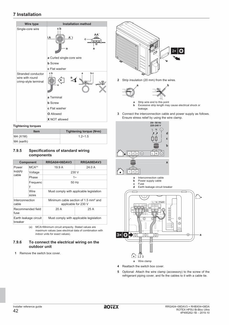
7 Installation
Installer reference guide
42RRGA04~08DAV3 + RHBX04+08DA
ROTEX HPSU Bi-Bloc Ultra4P495262-1B – 2019.10
Wire type Installation methodSingle-core wire c b
c
aa
AAA´
A´
a Curled single-core wire
b Screw
c Flat washerStranded conductorwire with roundcrimp-style terminal
c b ba c
a
BB
a Terminal
b Screw
c Flat washer
O Allowed
X NOT allowed
Tightening torquesItem Tightening torque (N•m)
M4 (X1M) 1.2~1.5M4 (earth)
7.9.5 Specifications of standard wiringcomponents
Component RRGA04+06DAV3 RRGA08DAV3Powersupplycable
MCA(a) 19.9 A 24.0 AVoltage 230 VPhase 1~Frequency
50 Hz
Wiresizes
Must comply with applicable legislation
Interconnectioncable
Minimum cable section of 1.5 mm² andapplicable for 230 V
Recommended fieldfuse
20 A 25 A
Earth leakage circuitbreaker
Must comply with applicable legislation
(a) MCA=Minimum circuit ampacity. Stated values aremaximum values (see electrical data of combination withindoor units for exact values).
7.9.6 To connect the electrical wiring on theoutdoor unit
1 Remove the switch box cover.
2×
2 Strip insulation (20 mm) from the wires.a b
a Strip wire end to this pointb Excessive strip length may cause electrical shock or
leakage.
3 Connect the interconnection cable and power supply as follows.Ensure stress relief by using the wire clamp.
a
cd
1N~ 50 Hz220-240 V
b
a Interconnection cableb Power supply cablec Fused Earth leakage circuit breaker
1 2 3 L N
L N PWR
12 3
3× a
a Wire clamp
4 Reattach the switch box cover.
5 Optional: Attach the wire clamp (accessory) to the screw of therefrigerant piping cover, and fix the cables to it with a cable tie.

7 Installation
Installer reference guide
43RRGA04~08DAV3 + RHBX04+08DAROTEX HPSU Bi-Bloc Ultra4P495262-1B – 2019.10
1×
1×
6 Connect an earth leakage circuit breaker and fuse to the powersupply line.
7.9.7 To connect the electrical wiring on theindoor unit
1 Open the switch box so that you can access the back of theswitch box. See "7.2.3 To open the indoor unit" [4 30].
2 Route the wiring as follows:
▪ Enter the unit from the bottom.▪ Route the wiring via the back of the switch box.▪ Fix the cables with cable ties to the cable tie mountings at
the back of the switch box.
a
X2M X1M
X5M
d e
b
b+ca
c
a, b, c Field wiring (see table below)d Factory-mounted cable for power supply of backup heatere Factory-mounted cable for power supply of booster heater
INFORMATIONWhen installing field supply or option cables, foreseesufficient cable length. This will make it possible to openthe switch box and gain access to other componentsduring service.
Routing Possible cables (depending on unit typeand installed options)
a
Low voltage
▪ Preferential power supply contact
▪ User interface used as room thermostat(option)
▪ Power consumption digital inputs (fieldsupply)
▪ Outdoor ambient temperature sensor(option)
▪ Indoor ambient temperature sensor(option)
▪ Electrical meters (field supply)
▪ Safety thermostat (field supply)
Routing Possible cables (depending on unit typeand installed options)
b
High voltage powersupply
▪ Interconnection cable
▪ Normal kWh rate power supply
▪ Preferential kWh rate power supplyc
High voltage controlsignal
▪ Heat pump convector (option)
▪ Room thermostat (option)
▪ Shut-off valve (field supply)
▪ Domestic hot water pump (field supply)
▪ Alarm output
▪ Changeover to external heat sourcecontrol
▪ Space cool/heat operation controld
High voltage powersupply (factory-mounted cable)
▪ Power supply for backup heater
e
High voltage powersupply (factory-mounted cable)
▪ Power supply for booster heater
CAUTIONDo NOT push or place redundant cable length in the unit.
7.9.8 To connect the main power supply1 Connect the main power supply.
In case of normal kWh rate power supply
X2MX1M
1 2 3
1 2 3
1 2 3
1 2 3
X1A
X11YBX11YA X11Y
1 2 3
a Interconnection cable (=main power supply)
In case of preferential kWh rate power supplyConnect X11Y to X11YB.
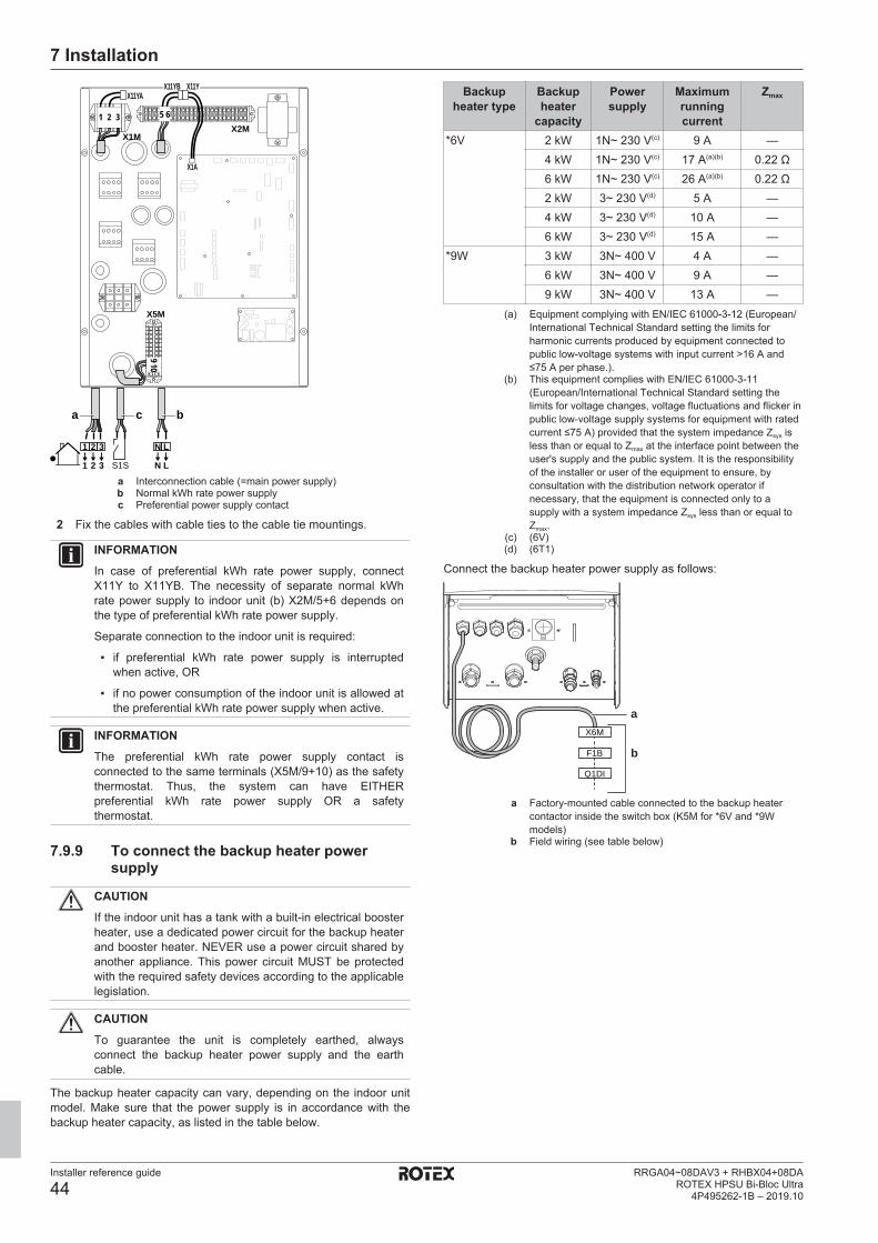
7 Installation
Installer reference guide
44RRGA04~08DAV3 + RHBX04+08DA
ROTEX HPSU Bi-Bloc Ultra4P495262-1B – 2019.10
X5M
X2MX1M
1 2 3
1 2
N L
N L3
S1S
a bc
X11YA
X1A
X11YB X11Y
910
51 2 3 6
a Interconnection cable (=main power supply)b Normal kWh rate power supplyc Preferential power supply contact
2 Fix the cables with cable ties to the cable tie mountings.
INFORMATIONIn case of preferential kWh rate power supply, connectX11Y to X11YB. The necessity of separate normal kWhrate power supply to indoor unit (b) X2M/5+6 depends onthe type of preferential kWh rate power supply.
Separate connection to the indoor unit is required:
▪ if preferential kWh rate power supply is interruptedwhen active, OR
▪ if no power consumption of the indoor unit is allowed atthe preferential kWh rate power supply when active.
INFORMATIONThe preferential kWh rate power supply contact isconnected to the same terminals (X5M/9+10) as the safetythermostat. Thus, the system can have EITHERpreferential kWh rate power supply OR a safetythermostat.
7.9.9 To connect the backup heater powersupply
CAUTIONIf the indoor unit has a tank with a built‑in electrical boosterheater, use a dedicated power circuit for the backup heaterand booster heater. NEVER use a power circuit shared byanother appliance. This power circuit MUST be protectedwith the required safety devices according to the applicablelegislation.
CAUTIONTo guarantee the unit is completely earthed, alwaysconnect the backup heater power supply and the earthcable.
The backup heater capacity can vary, depending on the indoor unitmodel. Make sure that the power supply is in accordance with thebackup heater capacity, as listed in the table below.
Backupheater type
Backupheater
capacity
Powersupply
Maximumrunningcurrent
Zmax
*6V 2 kW 1N~ 230 V(c) 9 A —4 kW 1N~ 230 V(c) 17 A(a)(b) 0.22 Ω6 kW 1N~ 230 V(c) 26 A(a)(b) 0.22 Ω2 kW 3~ 230 V(d) 5 A —4 kW 3~ 230 V(d) 10 A —6 kW 3~ 230 V(d) 15 A —
*9W 3 kW 3N~ 400 V 4 A —6 kW 3N~ 400 V 9 A —9 kW 3N~ 400 V 13 A —
(a) Equipment complying with EN/IEC 61000-3-12 (European/International Technical Standard setting the limits forharmonic currents produced by equipment connected topublic low-voltage systems with input current >16 A and≤75 A per phase.).
(b) This equipment complies with EN/IEC 61000‑3‑11(European/International Technical Standard setting thelimits for voltage changes, voltage fluctuations and flicker inpublic low-voltage supply systems for equipment with ratedcurrent ≤75 A) provided that the system impedance Zsys isless than or equal to Zmax at the interface point between theuser's supply and the public system. It is the responsibilityof the installer or user of the equipment to ensure, byconsultation with the distribution network operator ifnecessary, that the equipment is connected only to asupply with a system impedance Zsys less than or equal toZmax.
(c) (6V)(d) (6T1)
Connect the backup heater power supply as follows:
a
b
X6M
F1B
Q1DI
a Factory-mounted cable connected to the backup heatercontactor inside the switch box (K5M for *6V and *9Wmodels)
b Field wiring (see table below)
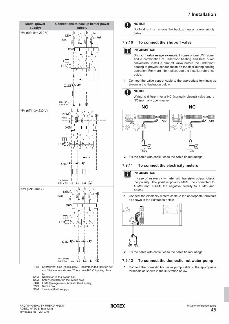
7 Installation
Installer reference guide
45RRGA04~08DAV3 + RHBX04+08DAROTEX HPSU Bi-Bloc Ultra4P495262-1B – 2019.10
Model (powersupply)
Connections to backup heater powersupply
*6V (6V: 1N~ 230 V)
1N~, 50 Hz230 V AC
SWB
4
3
6
5
2
1K5M
14
13
Q1DI
1
2
3
4
5
6
7
8
F1B II I I
NL
X6M
BR
N
GR
Y
BLU
1
BLU
2
*6V (6T1: 3~ 230 V)
SWB
3~, 50 Hz230 V AC
4
3
6
5
2
1K5M
14
13
1
2
3
4
5
6
7
8
F1B II I I
Q1DI
L1 L2 L3
X6M
BR
N
GR
Y
BLU
1
BLU
2
*9W (3N~ 400 V)
3N~, 50 Hz400 V AC
SWB
Q1DI
L1 L2 L3 N
1
2
3
4
5
6
7
8
F1B II I I
X6M
2
1K5M
4
3
6
5
14
13
BR
N
GR
YBLK BLU
F1B Overcurrent fuse (field supply). Recommended fuse for *6Vand *9W models: 4‑pole; 20 A; curve 400 V; tripping classC.
K1M Contactor (in the switch box)K5M Safety contactor (in the switch box)Q1DI Earth leakage circuit breaker (field supply)SWB Switch boxX6M Terminal (field supply)
NOTICEDo NOT cut or remove the backup heater power supplycable.
7.9.10 To connect the shut-off valve
INFORMATIONShut-off valve usage example. In case of one LWT zone,and a combination of underfloor heating and heat pumpconvectors, install a shut-off valve before the underfloorheating to prevent condensation on the floor during coolingoperation. For more information, see the installer referenceguide.
1 Connect the valve control cable to the appropriate terminals asshown in the illustration below.
NOTICEWiring is different for a NC (normally closed) valve and aNO (normally open) valve.
X2MX1M
X2MX1M
NO NC
M2S M2S
21 2921 28
2 Fix the cable with cable ties to the cable tie mountings.
7.9.11 To connect the electricity meters
INFORMATIONIn case of an electricity meter with transistor output, checkthe polarity. The positive polarity MUST be connected toX5M/6 and X5M/4; the negative polarity to X5M/5 andX5M/3.
1 Connect the electricity meters cable to the appropriate terminalsas shown in the illustration below.
X5M
S2S S3S
34 56
2 Fix the cable with cable ties to the cable tie mountings.
7.9.12 To connect the domestic hot water pump1 Connect the domestic hot water pump cable to the appropriate
terminals as shown in the illustration below.
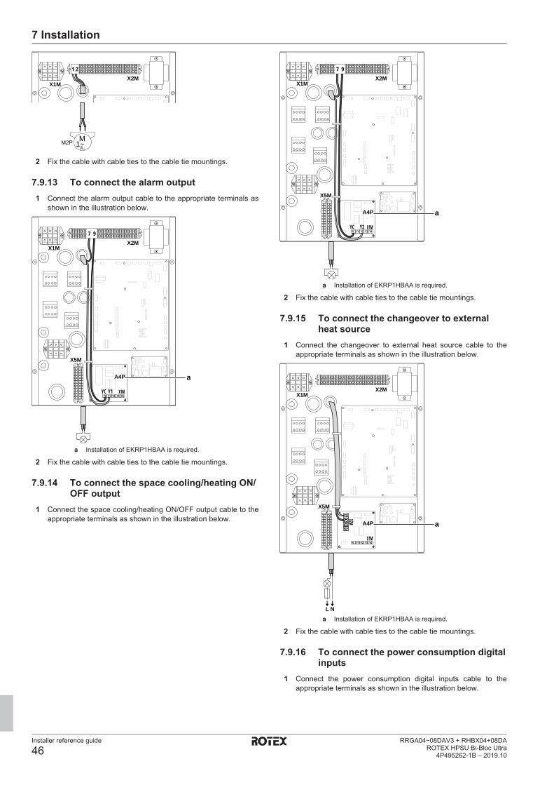
7 Installation
Installer reference guide
46RRGA04~08DAV3 + RHBX04+08DA
ROTEX HPSU Bi-Bloc Ultra4P495262-1B – 2019.10
X2MX1M
1~MM2P
1 2
2 Fix the cable with cable ties to the cable tie mountings.
7.9.13 To connect the alarm output1 Connect the alarm output cable to the appropriate terminals as
shown in the illustration below.
X5M
A4P
X1MYC Y1
YC Y1Y2 Y3 Y4
X2MX1M
7 9
a
a Installation of EKRP1HBAA is required.
2 Fix the cable with cable ties to the cable tie mountings.
7.9.14 To connect the space cooling/heating ON/OFF output
1 Connect the space cooling/heating ON/OFF output cable to theappropriate terminals as shown in the illustration below.
X5M
A4P
X1MYC Y1
YC Y2Y2 Y3 Y4
X2MX1M
7 9
a
a Installation of EKRP1HBAA is required.
2 Fix the cable with cable ties to the cable tie mountings.
7.9.15 To connect the changeover to externalheat source
1 Connect the changeover to external heat source cable to theappropriate terminals as shown in the illustration below.
X5M
A4P
X1MYC Y1 Y2 Y3 Y4
X2MX1M
X3X4X2M
X1X2
L N
a
a Installation of EKRP1HBAA is required.
2 Fix the cable with cable ties to the cable tie mountings.
7.9.16 To connect the power consumption digitalinputs
1 Connect the power consumption digital inputs cable to theappropriate terminals as shown in the illustration below.
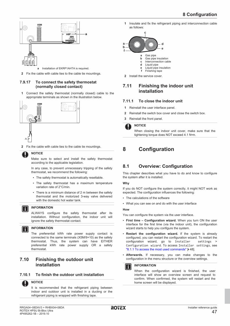
8 Configuration
Installer reference guide
47RRGA04~08DAV3 + RHBX04+08DAROTEX HPSU Bi-Bloc Ultra4P495262-1B – 2019.10
X5M
A8P
1 2 3 4 5X801M
S6S
S7S
S8S
S9S
a
a Installation of EKRP1AHTA is required.
2 Fix the cable with cable ties to the cable tie mountings.
7.9.17 To connect the safety thermostat(normally closed contact)
1 Connect the safety thermostat (normally closed) cable to theappropriate terminals as shown in the illustration below.
X5M
910
2 Fix the cable with cable ties to the cable tie mountings.
NOTICEMake sure to select and install the safety thermostataccording to the applicable legislation.
In any case, to prevent unnecessary tripping of the safetythermostat, we recommend the following:
▪ The safety thermostat is automatically resettable.
▪ The safety thermostat has a maximum temperaturevariation rate of 2°C/min.
▪ There is a minimum distance of 2 m between the safetythermostat and the motorized 3‑way valve deliveredwith the domestic hot water tank.
INFORMATIONALWAYS configure the safety thermostat after itsinstallation. Without configuration, the indoor unit willignore the safety thermostat contact.
INFORMATIONThe preferential kWh rate power supply contact isconnected to the same terminals (X5M/9+10) as the safetythermostat. Thus, the system can have EITHERpreferential kWh rate power supply OR a safetythermostat.
7.10 Finishing the outdoor unitinstallation
7.10.1 To finish the outdoor unit installation
NOTICEIt is recommended that the refrigerant piping betweenindoor and outdoor unit is installed in a ducting or therefrigerant piping is wrapped with finishing tape.
1 Insulate and fix the refrigerant piping and interconnection cableas follows:
fba
ed
c
a Gas pipeb Gas pipe insulationc Interconnection cabled Liquid pipee Liquid pipe insulationf Finishing tape
2 Install the service cover.
7.11 Finishing the indoor unitinstallation
7.11.1 To close the indoor unit1 Reinstall the user interface panel.
2 Reinstall the switch box cover and close the switch box.
3 Reinstall the front panel.
NOTICEWhen closing the indoor unit cover, make sure that thetightening torque does NOT exceed 4.1 N•m.
8 Configuration
8.1 Overview: ConfigurationThis chapter describes what you have to do and know to configurethe system after it is installed.
WhyIf you do NOT configure the system correctly, it might NOT work asexpected. The configuration influences the following:
▪ The calculations of the software
▪ What you can see on and do with the user interface
HowYou can configure the system via the user interface.
▪ First time – Configuration wizard. When you turn ON the userinterface for the first time (via the indoor unit), the configurationwizard starts to help you configure the system.
▪ Restart the configuration wizard. If the system is alreadyconfigured, you can restart the configuration wizard. To restart theconfiguration wizard, go to Installer settings >Configuration wizard. To access Installer settings, see"8.1.1 To access the most used commands" [4 48].
▪ Afterwards. If necessary, you can make changes to theconfiguration in the menu structure or the overview settings.
INFORMATIONWhen the configuration wizard is finished, the userinterface will show an overview screen and request toconfirm. When confirmed, the system will restart and thehome screen will be displayed.

8 Configuration
Installer reference guide
48RRGA04~08DAV3 + RHBX04+08DA
ROTEX HPSU Bi-Bloc Ultra4P495262-1B – 2019.10
Accessing settings – Legend for tablesYou can access the installer settings using two different methods.However, NOT all settings are accessible via both methods. If so,the corresponding table columns in this chapter are set to N/A (notapplicable).
Method Column in tablesAccessing settings via the breadcrumb in thehome menu screen or the menu structure.To enable breadcrumbs, press the buttonin the home screen.
#For example:
[9.1.5.2]
Accessing settings via the code in theoverview field settings.
CodeFor example: [C-07]
See also:
▪ "To access the installer settings" [4 48]
▪ "8.6 Menu structure: Overview installer settings" [4 79]
8.1.1 To access the most used commandsTo change the user permission levelYou can change the user permission level as follows:
1 Go to [B]: User profile.
User profile
B
2 Enter the applicable pin code for the user permissionlevel.
—
▪ Browse through the list of digits and change theselected digit.
▪ Move the cursor from left to right.▪ Confirm the pin code and proceed.
Installer pin code
The Installer pin code is 5678. Additional menu items andinstaller settings are now available.
5678Installer
Advanced user pin code
The Advanced user pin code is 1234. Additional menu items for theuser are now visible.
1234Advanced user
User pin code
The User pin code is 0000.
0000User
To access the installer settings1 Set the user permission level to Installer.
2 Go to [9]: Installer settings.
To modify an overview settingExample: Modify [1‑01] from 15 to 20.
Most settings can be configured via the menu structure. If for anyreason it is required to change a setting using the overview settings,then the overview settings can be accessed as follows:
1 Set the user permission level to Installer. See "Tochange the user permission level" [4 48].
—
2 Go to [9.I]: Installer settings > Overviewfield settings.
3 Turn the left dial to select the first part of the settingand confirm by pressing the dial.
00
01
02
0304
05
06
07
0809
0A
0B
0C
0D0E
0
123
4 Turn the left dial to select the second part of thesetting
00
01 1502
0304
05
06
07
0809
0A
0B
0C
0D0E
1
5 Turn the right dial to modify the value from 15 to 20.
00
01 2002
0304
05
06
07
0809
0A
0B
0C
0D0E
1
6 Press the left dial to confirm the new setting.7 Press the center button to go back to the home
screen.
INFORMATIONWhen you change the overview settings and you go backto the home screen, the user interface will show a popupscreen and request to restart the system.
When confirmed, the system will restart and recentchanges will be applied.
8.2 Configuration wizardAfter first power ON of the system, the user interface will guide youusing the configuration wizard. This way you can set the mostimportant initial settings. This way the unit will be able to runproperly. Afterwards, more detailed settings can be done via themenu structure if required.
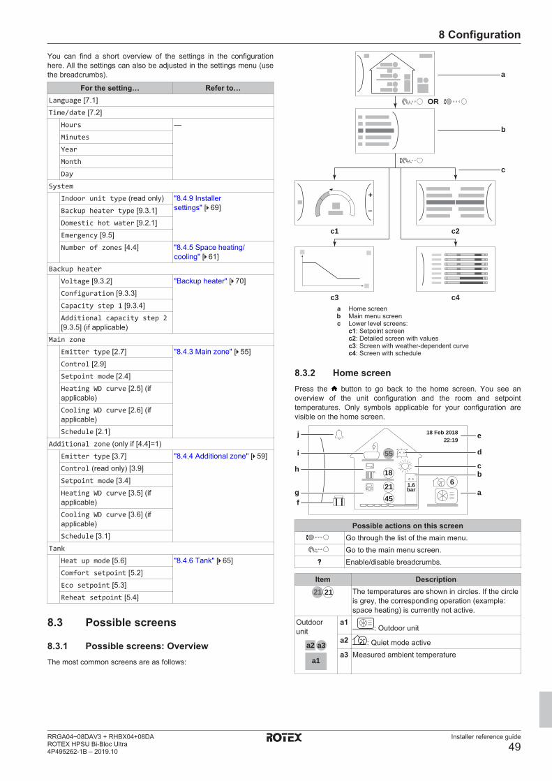
8 Configuration
Installer reference guide
49RRGA04~08DAV3 + RHBX04+08DAROTEX HPSU Bi-Bloc Ultra4P495262-1B – 2019.10
You can find a short overview of the settings in the configurationhere. All the settings can also be adjusted in the settings menu (usethe breadcrumbs).
For the setting… Refer to…Language [7.1]Time/date [7.2]
Hours —Minutes
Year
Month
Day
System
Indoor unit type (read only) "8.4.9 Installersettings" [4 69]Backup heater type [9.3.1]
Domestic hot water [9.2.1]Emergency [9.5]Number of zones [4.4] "8.4.5 Space heating/
cooling" [4 61]Backup heater
Voltage [9.3.2] "Backup heater" [4 70]Configuration [9.3.3]Capacity step 1 [9.3.4]Additional capacity step 2[9.3.5] (if applicable)
Main zone
Emitter type [2.7] "8.4.3 Main zone" [4 55]Control [2.9]Setpoint mode [2.4]Heating WD curve [2.5] (ifapplicable)Cooling WD curve [2.6] (ifapplicable)Schedule [2.1]
Additional zone (only if [4.4]=1)Emitter type [3.7] "8.4.4 Additional zone" [4 59]Control (read only) [3.9]Setpoint mode [3.4]Heating WD curve [3.5] (ifapplicable)Cooling WD curve [3.6] (ifapplicable)Schedule [3.1]
Tank
Heat up mode [5.6] "8.4.6 Tank" [4 65]Comfort setpoint [5.2]Eco setpoint [5.3]Reheat setpoint [5.4]
8.3 Possible screens
8.3.1 Possible screens: OverviewThe most common screens are as follows:
+
–
a
OR
b
c
c2
c4
c1
c3a Home screenb Main menu screenc Lower level screens:
c1: Setpoint screenc2: Detailed screen with valuesc3: Screen with weather-dependent curvec4: Screen with schedule
8.3.2 Home screenPress the button to go back to the home screen. You see anoverview of the unit configuration and the room and setpointtemperatures. Only symbols applicable for your configuration arevisible on the home screen.
61.6bar
18 Feb 201822:19
55
18
2145f
i
j
h
g
e
d
a
bc
Possible actions on this screenGo through the list of the main menu.Go to the main menu screen.Enable/disable breadcrumbs.
Item Description21 21 The temperatures are shown in circles. If the circle
is grey, the corresponding operation (example:space heating) is currently not active.
Outdoorunit
a2 a3
a1
a1: Outdoor unit
a2 : Quiet mode activea3 Measured ambient temperature
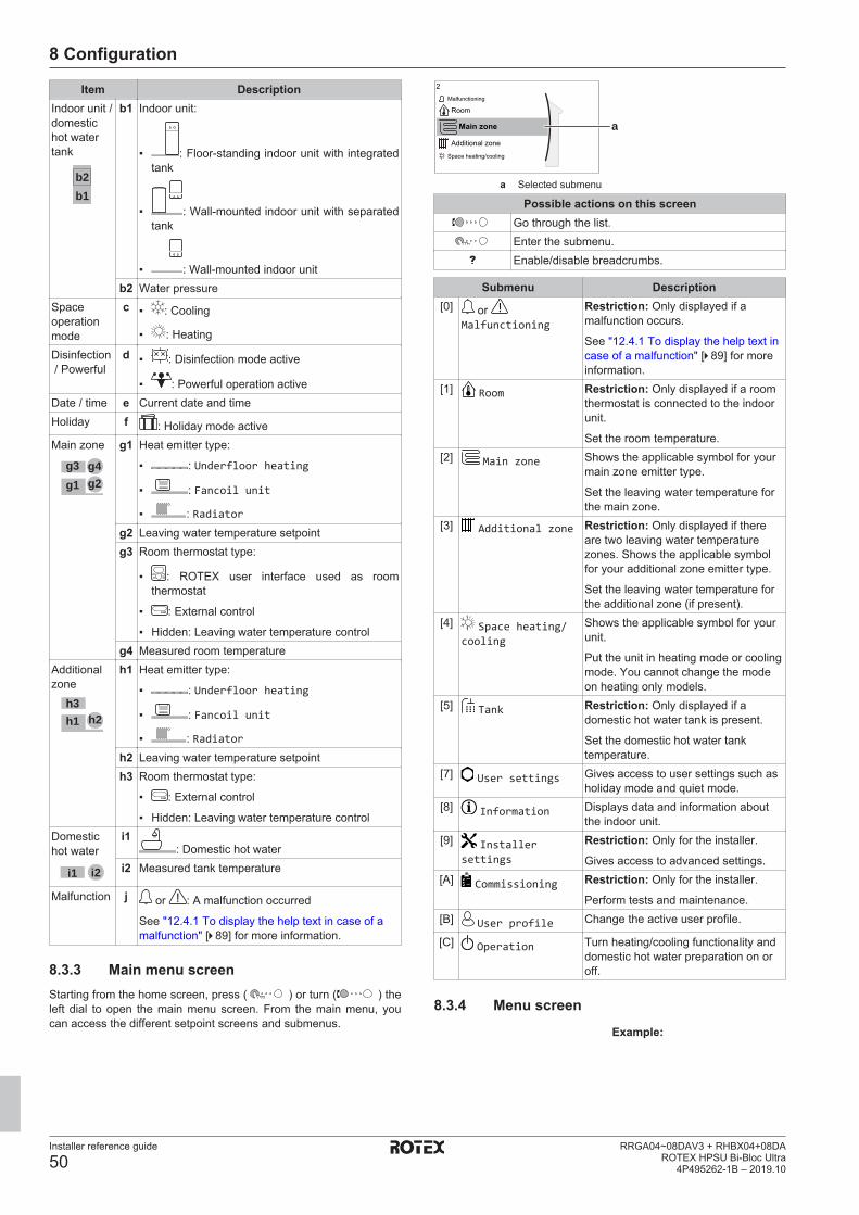
8 Configuration
Installer reference guide
50RRGA04~08DAV3 + RHBX04+08DA
ROTEX HPSU Bi-Bloc Ultra4P495262-1B – 2019.10
Item DescriptionIndoor unit /domestichot watertank
b1b2
b1 Indoor unit:
▪ : Floor-standing indoor unit with integratedtank
▪ : Wall-mounted indoor unit with separatedtank
▪ : Wall-mounted indoor unitb2 Water pressure
Spaceoperationmode
c ▪ : Cooling
▪ : Heating
Disinfection / Powerful
d ▪ : Disinfection mode active
▪ : Powerful operation activeDate / time e Current date and timeHoliday f : Holiday mode activeMain zone
g3g1
g4g2
g1 Heat emitter type:
▪ : Underfloor heating
▪ : Fancoil unit
▪ : Radiatorg2 Leaving water temperature setpointg3 Room thermostat type:
▪ : ROTEX user interface used as roomthermostat
▪ : External control
▪ Hidden: Leaving water temperature controlg4 Measured room temperature
Additionalzone
h3h1 h2
h1 Heat emitter type:
▪ : Underfloor heating
▪ : Fancoil unit
▪ : Radiatorh2 Leaving water temperature setpointh3 Room thermostat type:
▪ : External control
▪ Hidden: Leaving water temperature controlDomestichot water
i1 i2
i1: Domestic hot water
i2 Measured tank temperature
Malfunction j or : A malfunction occurred
See "12.4.1 To display the help text in case of amalfunction" [4 89] for more information.
8.3.3 Main menu screenStarting from the home screen, press ( ) or turn ( ) theleft dial to open the main menu screen. From the main menu, youcan access the different setpoint screens and submenus.
a
2
Main zone
Additional zone
RoomMalfunctioning
Space heating/cooling
a Selected submenu
Possible actions on this screenGo through the list.Enter the submenu.Enable/disable breadcrumbs.
Submenu Description[0] or
Malfunctioning
Restriction: Only displayed if amalfunction occurs.
See "12.4.1 To display the help text incase of a malfunction" [4 89] for moreinformation.
[1] Room Restriction: Only displayed if a roomthermostat is connected to the indoorunit.
Set the room temperature.[2] Main zone Shows the applicable symbol for your
main zone emitter type.
Set the leaving water temperature forthe main zone.
[3] Additional zone Restriction: Only displayed if thereare two leaving water temperaturezones. Shows the applicable symbolfor your additional zone emitter type.
Set the leaving water temperature forthe additional zone (if present).
[4] Space heating/cooling
Shows the applicable symbol for yourunit.
Put the unit in heating mode or coolingmode. You cannot change the modeon heating only models.
[5] Tank Restriction: Only displayed if adomestic hot water tank is present.
Set the domestic hot water tanktemperature.
[7] User settings Gives access to user settings such asholiday mode and quiet mode.
[8] Information Displays data and information aboutthe indoor unit.
[9] Installersettings
Restriction: Only for the installer.
Gives access to advanced settings.[A] Commissioning Restriction: Only for the installer.
Perform tests and maintenance.[B] User profile Change the active user profile.
[C] Operation Turn heating/cooling functionality anddomestic hot water preparation on oroff.
8.3.4 Menu screenExample:
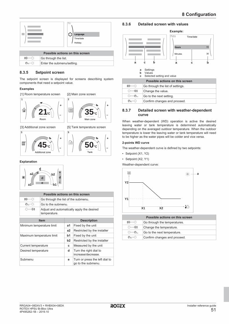
8 Configuration
Installer reference guide
51RRGA04~08DAV3 + RHBX04+08DAROTEX HPSU Bi-Bloc Ultra4P495262-1B – 2019.10
7.1
Language
Time/date
Holiday
Possible actions on this screenGo through the list.Enter the submenu/setting.
8.3.5 Setpoint screenThe setpoint screen is displayed for screens describing systemcomponents that need a setpoint value.
Examples[1] Room temperature screen
+
–21°C
1
Room
[2] Main zone screen
+
–35°C
2
Main zone
[3] Additional zone screen
+
–45°C
3
Additional zone
[5] Tank temperature screen
+
–50°C
5
Tank
Explanation
a1
d+
–de d
e
ca2
b1
b2
Possible actions on this screenGo through the list of the submenu.Go to the submenu.Adjust and automatically apply the desiredtemperature.
Item DescriptionMinimum temperature limit a1 Fixed by the unit
a2 Restricted by the installerMaximum temperature limit b1 Fixed by the unit
b2 Restricted by the installerCurrent temperature c Measured by the unitDesired temperature d Turn the right dial to
increase/decrease.Submenu e Turn or press the left dial to
go to the submenu.
8.3.6 Detailed screen with valuesExample:
a bc a bc
7.2.1 Time/date
Hours 11
30Minutes
a Settingsb Valuesc Selected setting and value
Possible actions on this screenGo through the list of settings.Change the value.Go to the next setting.Confirm changes and proceed.
8.3.7 Detailed screen with weather-dependentcurve
When weather-dependent (WD) operation is active the desiredleaving water or tank temperature is determined automaticallydepending on the averaged outdoor temperature. When the outdoortemperature is lower the leaving water or tank temperature will needto be higher as the water pipes will be colder and vice versa.
2-points WD curveThe weather-dependent curve is defined by two setpoints:
▪ Setpoint (X1, Y2)
▪ Setpoint (X2, Y1)
Weather-dependent curve:
Y1
Y2
X1 X2
a
Possible actions on this screenGo through the temperatures.Change the temperature.Go to the next temperature.Confirm changes and proceed.

8 Configuration
Installer reference guide
52RRGA04~08DAV3 + RHBX04+08DA
ROTEX HPSU Bi-Bloc Ultra4P495262-1B – 2019.10
Item Descriptiona Selected weather dependent zone:
▪ : Main zone or additional zone heating
▪ : Main zone or additional zone cooling
▪ : Domestic hot waterX1, X2 Examples of outdoor ambient temperatureY1, Y2 Examples of desired tank temperature or leaving water
temperature. The icon corresponds to the heat emitterfor that zone:
▪ : Underfloor heating
▪ : Fan coil unit
▪ : Radiator
▪ : Domestic hot water tank
8.3.8 Schedule screen: ExampleThis example shows how to set a room temperature schedule inheating mode for the main zone.
INFORMATIONThe procedures to program other schedules are similar.
To program the schedule: overviewExample: You want to program the following schedule:
Mon
Sat
Wed
FriThu
Tue
Sun
User defined 1
Prerequisite: The room temperature schedule is only available ifroom thermostat control is active. If leaving water temperaturecontrol is active, you can program the main zone schedule instead.
1 Go to the schedule.
2 (optional) Clear the content of the whole week schedule or thecontent of a selected day schedule.
3 Program the schedule for Monday.
4 Copy the schedule to the other weekdays.
5 Program the schedule for Saturday and copy it to Sunday.
6 Give the schedule a name.
To go to the schedule:1 Go to [1.1]: Room > Schedule.2 Set scheduling to Yes.3 Go to [1.2]: Room > Heating schedule.
To clear the content of the week schedule:1 Select the name of the current schedule.
Mon
Sat
Wed
FriThu
Tue
Sun
User defined 1
2 Select Delete.
DeleteRenameSelect
3 Select OK to confirm.
To clear the content of a day schedule:1 Select the day of which you want to clear the
content. For example Friday
Mon
Sat
Wed
FriThu
Tue
Sun
User defined 1C
2 Select Delete.
Delete
Edit
Copy
3 Select OK to confirm.
To program the schedule for Monday:1 Select Monday.
Mon
Sat
Wed
FriThu
Tue
Sun
User defined 1
2 Select Edit.
Delete
Edit
Copy
3 Use the left dial to select an entry and edit the entrywith the right dial. You can program up to 6 actionseach day. On the bar, a high temperature has adarker colour than a low temperature.
0
6:00
8:30
17:30
20°C
18°C
22:00--:--
18°C
--
21°C
12 24Mon
Note: To clear an action, set its time as the time ofthe previous action.
4 Confirm the changes.
Result: The schedule for Monday is defined. Thevalue of the last action is valid until the nextprogrammed action. In this example, Monday is thefirst day you programmed. Thus, the lastprogrammed action is valid up to the first action ofnext Monday.

8 Configuration
Installer reference guide
53RRGA04~08DAV3 + RHBX04+08DAROTEX HPSU Bi-Bloc Ultra4P495262-1B – 2019.10
To copy the schedule to the other weekdays:1 Select Monday.
Mon
Sat
Wed
FriThu
Tue
Sun
User defined 1
2 Select Copy.
Delete
Edit
Copy
Result: Next to the copied day, "C" is displayed.3 Select Tuesday.
Mon
Sat
Wed
FriThu
Tue
Sun
User defined 1C
4 Select Paste.
Delete
Edit
Copy
Paste
Result:
Mon
Sat
Wed
FriThu
Tue
Sun
User defined 1C
5 Repeat this action for all other weekdays.
Mon
Sat
Wed
FriThu
Tue
Sun
User defined 1C
—
To program the schedule for Saturday and copy it to Sunday:1 Select Saturday.2 Select Edit.3 Use the left dial to select an entry and edit the entry
with the right dial.
0
8:00
23:00--:--
21°C
18°C
--
12 24Sat
4 Confirm the changes.5 Select Saturday.6 Select Copy.
7 Select Sunday.8 Select Paste.
Result:
Mon
Sat
Wed
FriThu
Tue
Sun
User defined 1
C
To rename the schedule:1 Select the name of the current schedule.
Mon
Sat
Wed
FriThu
Tue
Sun
User defined 1
2 Select Rename.
DeleteRenameSelect
3 (optional) To delete the current schedule name,browse through the character list until ← isdisplayed, then press to remove the previouscharacter. Repeat for each character of the schedulename.
4 To name the current schedule, browse through thecharacter list and confirm the selected character.The schedule name can contain up to 15 characters.
5 Confirm the new name.
INFORMATIONNot all schedules can be renamed.
8.4 Settings menuYou can set additional settings using the main menu screen and itssubmenus. The most important settings are presented here.
8.4.1 Malfunctioning
In case of a malfunction, or will appear on the home screen.To display the error code, open the menu screen and go to[0] Malfunctioning. Press for more information about the error.0
Malfunctioning
Room
OperationUser profile
Main zone
8.4.2 RoomSetpoint screenControl the room temperature of the main zone via setpoint screen[1] Room.
See "8.3.5 Setpoint screen" [4 51].
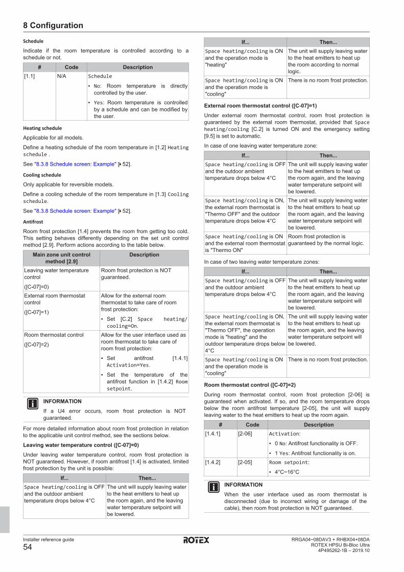
8 Configuration
Installer reference guide
54RRGA04~08DAV3 + RHBX04+08DA
ROTEX HPSU Bi-Bloc Ultra4P495262-1B – 2019.10
Schedule
Indicate if the room temperature is controlled according to aschedule or not.
# Code Description[1.1] N/A Schedule
▪ No: Room temperature is directlycontrolled by the user.
▪ Yes: Room temperature is controlledby a schedule and can be modified bythe user.
Heating schedule
Applicable for all models.
Define a heating schedule of the room temperature in [1.2] Heatingschedule .
See "8.3.8 Schedule screen: Example" [4 52].
Cooling schedule
Only applicable for reversible models.
Define a cooling schedule of the room temperature in [1.3] Coolingschedule.
See "8.3.8 Schedule screen: Example" [4 52].
Antifrost
Room frost protection [1.4] prevents the room from getting too cold.This setting behaves differently depending on the set unit controlmethod [2.9]. Perform actions according to the table below.
Main zone unit controlmethod [2.9]
Description
Leaving water temperaturecontrol
([C‑07]=0)
Room frost protection is NOTguaranteed.
External room thermostatcontrol
([C‑07]=1)
Allow for the external roomthermostat to take care of roomfrost protection:
▪ Set [C.2] Space heating/cooling=On.
Room thermostat control
([C‑07]=2)
Allow for the user interface used asroom thermostat to take care ofroom frost protection:
▪ Set antifrost [1.4.1]Activation=Yes.
▪ Set the temperature of theantifrost function in [1.4.2] Roomsetpoint.
INFORMATIONIf a U4 error occurs, room frost protection is NOTguaranteed.
For more detailed information about room frost protection in relationto the applicable unit control method, see the sections below.
Leaving water temperature control ([C‑07]=0)Under leaving water temperature control, room frost protection isNOT guaranteed. However, if room antifrost [1.4] is activated, limitedfrost protection by the unit is possible:
If... Then...Space heating/cooling is OFFand the outdoor ambienttemperature drops below 4°C
The unit will supply leaving waterto the heat emitters to heat upthe room again, and the leavingwater temperature setpoint willbe lowered.
If... Then...Space heating/cooling is ONand the operation mode is"heating"
The unit will supply leaving waterto the heat emitters to heat upthe room according to normallogic.
Space heating/cooling is ONand the operation mode is"cooling"
There is no room frost protection.
External room thermostat control ([C‑07]=1)Under external room thermostat control, room frost protection isguaranteed by the external room thermostat, provided that Spaceheating/cooling [C.2] is turned ON and the emergency setting[9.5] is set to automatic.
In case of one leaving water temperature zone:
If... Then...Space heating/cooling is OFFand the outdoor ambienttemperature drops below 4°C
The unit will supply leaving waterto the heat emitters to heat upthe room again, and the leavingwater temperature setpoint willbe lowered.
Space heating/cooling is ON,the external room thermostat is"Thermo OFF" and the outdoortemperature drops below 4°C
The unit will supply leaving waterto the heat emitters to heat upthe room again, and the leavingwater temperature setpoint willbe lowered.
Space heating/cooling is ONand the external room thermostatis "Thermo ON"
Room frost protection isguaranteed by the normal logic.
In case of two leaving water temperature zones:
If... Then...Space heating/cooling is OFFand the outdoor ambienttemperature drops below 4°C
The unit will supply leaving waterto the heat emitters to heat upthe room again, and the leavingwater temperature setpoint willbe lowered.
Space heating/cooling is ON,the external room thermostat is"Thermo OFF", the operationmode is "heating" and theoutdoor temperature drops below4°C
The unit will supply leaving waterto the heat emitters to heat upthe room again, and the leavingwater temperature setpoint willbe lowered.
Space heating/cooling is ONand the operation mode is"cooling"
There is no room frost protection.
Room thermostat control ([C‑07]=2)During room thermostat control, room frost protection [2‑06] isguaranteed when activated. If so, and the room temperature dropsbelow the room antifrost temperature [2‑05], the unit will supplyleaving water to the heat emitters to heat up the room again.
# Code Description[1.4.1] [2-06] Activation:
▪ 0 No: Antifrost functionality is OFF.
▪ 1 Yes: Antifrost functionality is on.[1.4.2] [2-05] Room setpoint:
▪ 4°C~16°C
INFORMATIONWhen the user interface used as room thermostat isdisconnected (due to incorrect wiring or damage of thecable), then room frost protection is NOT guaranteed.

8 Configuration
Installer reference guide
55RRGA04~08DAV3 + RHBX04+08DAROTEX HPSU Bi-Bloc Ultra4P495262-1B – 2019.10
NOTICEIf Emergency is set to Manual ([9.5]=0), and the unit istriggered to start emergency operation, the unit will stopand need to be recovered manually via the user interface.To recover operation manually, go to the Malfunctioningmain menu screen, where the user interface will then askyou to confirm emergency operation before starting.
Room frost protection is active even if the user does NOTconfirm emergency operation.
Setpoint range
Only applicable in room thermostat control.
To save energy by preventing overheating or undercooling the room,you can limit the range of the room temperature for heating and/orcooling.
NOTICEWhen adjusting the room temperature ranges, all desiredroom temperatures are also adjusted to guarantee they arebetween the limits.
# Code Description[1.5.1] [3-07] Heating minimum
[1.5.2] [3-06] Heating maximum
[1.5.3] [3-09] Cooling minimum
[1.5.4] [3-08] Cooling maximum
Room sensor offset
Only applicable in room thermostat control.
To calibrate the (external) room temperature sensor, give an offsetto the value of the room thermistor as measured by the userinterface used as room thermostat or by the external room sensor.The setting can be used to compensate for situations where the userinterface used as room thermostat or the external room sensorcannot be installed on the ideal installation location.
See "5.7 Setting up an external temperature sensor" [4 21]).
# Code Description[1.6] [2-0A] Room sensor offset (user interface
used as room thermostat): Offset on theactual room temperature measured onthe user interface used as roomthermostat.
▪ –5°C~5°C, step 0.5°C[1.7] [2-09] Room sensor offset (external room
sensor option): Only applicable if theexternal room sensor option is installedand configured.
▪ –5°C~5°C, step 0.5°C
8.4.3 Main zoneSetpoint screenControl the leaving water temperature for the main zone via setpointscreen [2] Main zone.
See "8.3.5 Setpoint screen" [4 51].
Schedule
Indicate if the temperature of the leaving water is defined accordingto a schedule or not.
Influence of the LWT setpoint mode [2.4] is as follows:
▪ In Fixed LWT setpoint mode, the scheduled actions consist ofdesired leaving water temperatures, either preset or custom.
▪ In Weather dependent LWT setpoint mode, the scheduledactions consist of desired shift actions, either preset or custom.
# Code Description[2.1] N/A Schedule
▪ 0: No
▪ 1: Yes
Heating scheduleDefine a heating temperature schedule for the main zone via [2.2]Heating schedule.
See "8.3.8 Schedule screen: Example" [4 52].
Cooling scheduleDefine a cooling temperature schedule for the main zone via [2.3]Cooling schedule.
See "8.3.8 Schedule screen: Example" [4 52].
Setpoint mode
Define the setpoint mode:
▪ Fixed: the desired leaving water temperature does not depend onthe outdoor ambient temperature.
▪ In WD heating, fixed cooling mode, the desired leaving watertemperature:
▪ depends on the outdoor ambient temperature for heating
▪ does NOT depend on the outdoor ambient temperature forcooling
▪ In Weather dependent mode, the desired leaving watertemperature depends on the outdoor ambient temperature.
# Code Description[2.4] N/A Setpoint mode
▪ Fixed
▪ WD heating, fixed cooling
▪ Weather dependent
When weather dependent operation is active, low outdoortemperatures will result in warmer water and vice versa. Duringweather dependent operation, the user can shift the watertemperature up or down by a maximum of 10°C.
Heating WD curveSet weather-dependent heating for the main zone (if [2.4]=1 or 2):
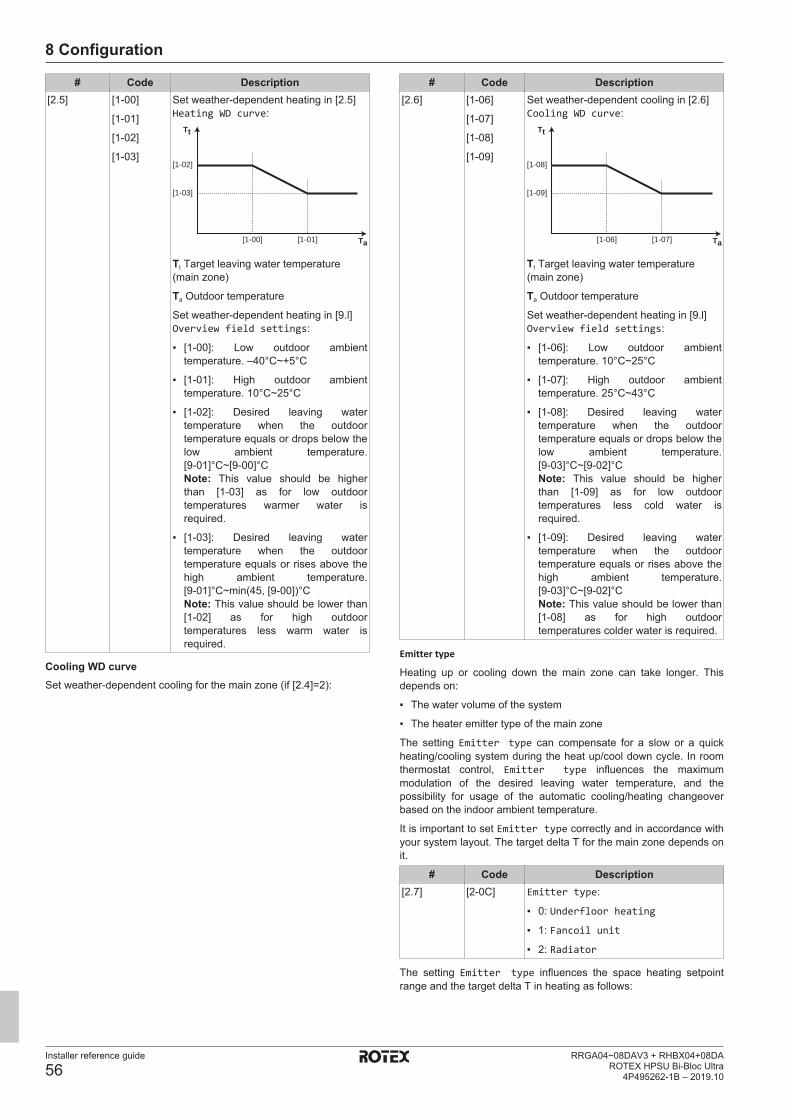
8 Configuration
Installer reference guide
56RRGA04~08DAV3 + RHBX04+08DA
ROTEX HPSU Bi-Bloc Ultra4P495262-1B – 2019.10
# Code Description[2.5] [1-00]
[1-01]
[1-02]
[1-03]
Set weather-dependent heating in [2.5]Heating WD curve:
[1-03]
[1-02]
Ta
Tt
[1-00] [1-01]
Tt Target leaving water temperature(main zone)
Ta Outdoor temperature
Set weather-dependent heating in [9.l]Overview field settings:
▪ [1-00]: Low outdoor ambienttemperature. –40°C~+5°C
▪ [1-01]: High outdoor ambienttemperature. 10°C~25°C
▪ [1-02]: Desired leaving watertemperature when the outdoortemperature equals or drops below thelow ambient temperature.[9‑01]°C~[9‑00]°CNote: This value should be higherthan [1‑03] as for low outdoortemperatures warmer water isrequired.
▪ [1-03]: Desired leaving watertemperature when the outdoortemperature equals or rises above thehigh ambient temperature.[9‑01]°C~min(45, [9‑00])°CNote: This value should be lower than[1‑02] as for high outdoortemperatures less warm water isrequired.
Cooling WD curveSet weather-dependent cooling for the main zone (if [2.4]=2):
# Code Description[2.6] [1-06]
[1-07]
[1-08]
[1-09]
Set weather-dependent cooling in [2.6]Cooling WD curve:
[1-09]
[1-08]
Ta
Tt
[1-06] [1-07]
Tt Target leaving water temperature(main zone)
Ta Outdoor temperature
Set weather-dependent heating in [9.l]Overview field settings:
▪ [1-06]: Low outdoor ambienttemperature. 10°C~25°C
▪ [1-07]: High outdoor ambienttemperature. 25°C~43°C
▪ [1-08]: Desired leaving watertemperature when the outdoortemperature equals or drops below thelow ambient temperature.[9‑03]°C~[9‑02]°CNote: This value should be higherthan [1‑09] as for low outdoortemperatures less cold water isrequired.
▪ [1-09]: Desired leaving watertemperature when the outdoortemperature equals or rises above thehigh ambient temperature.[9‑03]°C~[9-02]°CNote: This value should be lower than[1‑08] as for high outdoortemperatures colder water is required.
Emitter type
Heating up or cooling down the main zone can take longer. Thisdepends on:
▪ The water volume of the system
▪ The heater emitter type of the main zone
The setting Emitter type can compensate for a slow or a quickheating/cooling system during the heat up/cool down cycle. In roomthermostat control, Emitter type influences the maximummodulation of the desired leaving water temperature, and thepossibility for usage of the automatic cooling/heating changeoverbased on the indoor ambient temperature.
It is important to set Emitter type correctly and in accordance withyour system layout. The target delta T for the main zone depends onit.
# Code Description[2.7] [2‑0C] Emitter type:
▪ 0: Underfloor heating
▪ 1: Fancoil unit
▪ 2: Radiator
The setting Emitter type influences the space heating setpointrange and the target delta T in heating as follows:

8 Configuration
Installer reference guide
57RRGA04~08DAV3 + RHBX04+08DAROTEX HPSU Bi-Bloc Ultra4P495262-1B – 2019.10
Emitter type Mainzone
Space heatingsetpoint range[9‑01]~[9‑00]
Target delta T inheating [1‑0B]
0: Underfloorheating
Maximum 55°C Variable (see [2.B])
1: Fancoil unit Maximum 55°C Variable (see [2.B])2: Radiator Maximum 65°C Fixed 10°C
NOTICEThe maximum setpoint in space heating depends on theemitter type as can be seen in above table. If there are 2water temperature zones, then the maximum setpoint isthe maximum of the 2 zones.
CAUTIONNOT configuring the system in the following way can causedamage to the heat emitters. If there are 2 zones, it isimportant that in heating:
▪ the zone with the lowest water temperature isconfigured as the main zone, and
▪ the zone with the highest water temperature isconfigured as the additional zone.
CAUTIONIf there are 2 zones and the emitter types are wronglyconfigured, water of high temperature can be sent towardsa low temperature emitter (underfloor heating). To avoidthis:
▪ Install an aquastat/thermostatic valve to avoid too hightemperatures towards a low temperature emitter.
▪ Make sure you set the emitter types for the main zone[2.7] and for the additional zone [3.7] correctly inaccordance with the connected emitter.
INFORMATIONDepending on the target delta T, the average emittertemperature will vary. To counteract the effect on theaverage emitter temperature due to a higher delta T target,the leaving water setpoint (fixed or weather dependent)can be adjusted.
Setpoint range
To prevent a wrong (i.e. too hot or too cold) leaving watertemperature for the main leaving water temperature zone, limit itstemperature range.
NOTICEIn case of a floor heating application it is important to limitthe:
▪ maximum leaving water temperature at heatingoperation according to the specifications of the floorheating installation.
▪ the minimum leaving water temperature at coolingoperation to 18~20°C to prevent condensation on thefloor.
NOTICE▪ When adjusting the leaving water temperature ranges,
all desired leaving water temperatures are alsoadjusted to guarantee they are between the limits.
▪ Always balance between the desired leaving watertemperature with the desired room temperature and/orthe capacity (according to the design and selection ofthe heat emitters). The desired leaving watertemperature is the result of several settings (presetvalues, shift values, weather-dependent curves,modulation). As a result, too high or too low leavingwater temperatures could occur which lead toovertemperatures or capacity shortage. By limiting theleaving water temperature range to adequate values(depending on the heat emitter), such situations can beavoided.
Example: In heating mode, leaving water temperatures must besufficiently higher than the room temperatures. To avoid that theroom cannot heat up as desired, set the minimum leaving watertemperature to 28°C.
# Code DescriptionLeaving water temperature range for the main leaving watertemperature zone (= the leaving water temperature zone with thelowest leaving water temperature in heating operation and thehighest leaving water temperature in cooling operation)[2.8.1] [9-01] Heating minimum:
▪ 15°C~37°C[2.8.2] [9-00] Heating maximum:
▪ [2‑0C]=2 (emitter type main zone =radiator)37°C~60°C
▪ Otherwise: 37°C~55°C[2.8.3] [9-02] Cooling minimum:
▪ 5°C~18°C[2.8.4] [9-03] Cooling maximum:
▪ 18°C~22°C
# Code DescriptionLeaving water temperature range for the main leaving watertemperature zone (= the leaving water temperature zone with thelowest leaving water temperature in heating operation and thehighest leaving water temperature in cooling operation)[2.8.1] [9-01] Heating minimum:
▪ 15°C~37°C[2.8.2] [9-00] Heating maximum:
▪ [2‑0C]=2 (emitter type main zone =radiator)37°C~70°C
▪ Otherwise: 37°C~55°C[2.8.3] [9-02] Cooling minimum:
▪ 5°C~18°C[2.8.4] [9-03] Cooling maximum:
▪ 18°C~22°C

8 Configuration
Installer reference guide
58RRGA04~08DAV3 + RHBX04+08DA
ROTEX HPSU Bi-Bloc Ultra4P495262-1B – 2019.10
Control
Define how the operation of the unit is controlled.
Control In this control...Leaving water Unit operation is decided based on the leaving
water temperature regardless the actual roomtemperature and/or heating or cooling demandof the room.
External roomthermostat
Unit operation is decided by the externalthermostat or equivalent (e.g. heat pumpconvector).
Room thermostat Unit operation is decided based on the ambienttemperature of the user interface used as aroom thermostat.
# Code Description[2.9] [C‑07] ▪ 0: Leaving water
▪ 1: External room thermostat
▪ 2: Room thermostat
Thermostat type
Only applicable in external room thermostat control.
NOTICEIf an external room thermostat is used, the external roomthermostat will control the room frost protection. However,the room frost protection is only possible if [C.2] Spaceheating/cooling=On.
# Code Description[2.A] [C‑05] External room thermostat type for the
main zone:
▪ 1: 1 contact: The used external roomthermostat can only send a thermoON/OFF condition. There is noseparation between heating or coolingdemand. The room thermostat isconnected to only 1 digital input(X2M/35).Select this value in case of aconnection to the heat pump convector(FWXV).
▪ 2: 2 contacts: The used externalroom thermostat can send a separateheating/cooling thermo ON/OFFcondition. The room thermostat isconnected to 2 digital inputs (X2M/35and X2M/34).Select this value in case of aconnection to the wired (RKRTWA) orwireless (RKRTR1) room thermostat
Leaving water temperature: Delta T
In heating for the main zone, the target delta T (temperaturedifference) depends on the selected emitter type for the main zone.
The difference delta T indicates, depends on the operation mode:
▪ In heating mode, delta T indicates the temperature differencebetween the leaving water setpoint and entering water.
▪ In cooling mode, delta T indicates the temperature differencebetween entering and leaving water temperature.
The unit is designed to support underfloor loops operation. Therecommended leaving water temperature for underfloor loops is35°C. In such case, the unit will realize a temperature difference of5°C, which means that the entering water temperature is around30°C.
Depending on the installed type of heat emitters (radiators, heatpump convector, underfloor loops) or situation, you can change thedifference between entering and leaving water temperature.
Note: : The pump will regulate its flow to keep the delta T. In somespecial cases, the measured delta T can differ from the set value.
INFORMATIONWhen only the backup heater is active in heating, delta Twill be controlled according to the fixed capacity of thebackup heater. It is possible that this delta T is differentfrom the selected target delta T.
INFORMATIONIn heating, the target delta T will only be achieved aftersome operation time, when the setpoint is being reached,because of the big difference between leaving watertemperature setpoint and inlet temperature at startup.
INFORMATIONIf the main zone or the additional zone has a heatingdemand, and this zone is equipped with radiators, then thetarget delta T that the unit will use in heating operation willbe 10°C fixed.
If the zones are not equipped with radiators, then inheating the unit will give priority to the target delta T for theadditional zone, if there is a heating demand in theadditional zone.
In cooling the unit will give priority to the target delta T forthe additional zone, if there is a cooling demand in theadditional zone.
# Code Description[2.B.1] [1‑0B] Delta T heating: A minimum
temperature difference is required forproper operation of heat emitters inheating mode.
▪ If [2-0C]=2, this is fixed to 10°C
▪ Else: 3°C~10°C[2.B.2] [1‑0D] Delta T cooling: A minimum
temperature difference is required forproper operation of heat emitters incooling mode.
▪ 3°C~10°C
Leaving water temperature: Modulation
Only applicable in case of room thermostat control.
When using the room thermostat functionality, the customer needsto set the desired room temperature. The unit will supply hot water tothe heat emitters and the room will be heated.
Additionally, also the desired leaving water temperature must beconfigured: if Modulation is enabled, the unit automaticallycalculates the desired leaving water temperature. These calculationsare based on:
▪ the preset temperatures, or
▪ the desired weather-dependent temperatures (if weather-dependent is enabled)
Moreover, with Modulation enabled, the desired leaving watertemperature is lowered or raised in function of the desired roomtemperature and the difference between the actual and the desiredroom temperature. This results in:
▪ stable room temperatures, exactly matching the desiredtemperature (higher comfort level)
▪ less on/off cycles (lower noise level, higher comfort and higherefficiency)
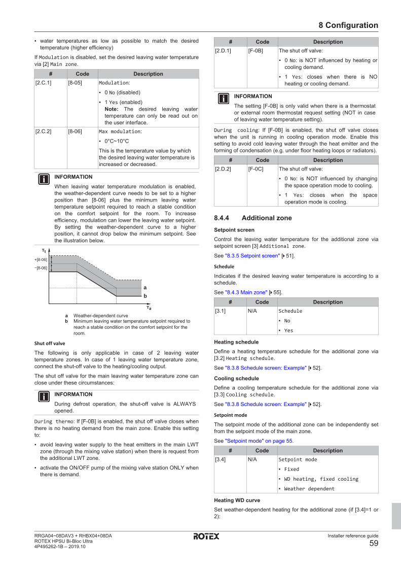
8 Configuration
Installer reference guide
59RRGA04~08DAV3 + RHBX04+08DAROTEX HPSU Bi-Bloc Ultra4P495262-1B – 2019.10
▪ water temperatures as low as possible to match the desiredtemperature (higher efficiency)
If Modulation is disabled, set the desired leaving water temperaturevia [2] Main zone.
# Code Description[2.C.1] [8‑05] Modulation:
▪ 0 No (disabled)
▪ 1 Yes (enabled)Note: The desired leaving watertemperature can only be read out onthe user interface.
[2.C.2] [8‑06] Max modulation:
▪ 0°C~10°C
This is the temperature value by whichthe desired leaving water temperature isincreased or decreased.
INFORMATIONWhen leaving water temperature modulation is enabled,the weather‑dependent curve needs to be set to a higherposition than [8-06] plus the minimum leaving watertemperature setpoint required to reach a stable conditionon the comfort setpoint for the room. To increaseefficiency, modulation can lower the leaving water setpoint.By setting the weather‑dependent curve to a higherposition, it cannot drop below the minimum setpoint. Seethe illustration below.
a
+[8-06]
−[8-06]
b
Ta
Tt
a Weather-dependent curveb Minimum leaving water temperature setpoint required to
reach a stable condition on the comfort setpoint for theroom.
Shut off valve
The following is only applicable in case of 2 leaving watertemperature zones. In case of 1 leaving water temperature zone,connect the shut-off valve to the heating/cooling output.
The shut off valve for the main leaving water temperature zone canclose under these circumstances:
INFORMATIONDuring defrost operation, the shut-off valve is ALWAYSopened.
During thermo: If [F‑0B] is enabled, the shut off valve closes whenthere is no heating demand from the main zone. Enable this settingto:
▪ avoid leaving water supply to the heat emitters in the main LWTzone (through the mixing valve station) when there is request fromthe additional LWT zone.
▪ activate the ON/OFF pump of the mixing valve station ONLY whenthere is demand.
# Code Description[2.D.1] [F-0B] The shut off valve:
▪ 0 No: is NOT influenced by heating orcooling demand.
▪ 1 Yes: closes when there is NOheating or cooling demand.
INFORMATIONThe setting [F‑0B] is only valid when there is a thermostator external room thermostat request setting (NOT in caseof leaving water temperature setting).
During cooling: If [F‑0B] is enabled, the shut off valve closeswhen the unit is running in cooling operation mode. Enable thissetting to avoid cold leaving water through the heat emitter and theforming of condensation (e.g. under floor heating loops or radiators).
# Code Description[2.D.2] [F-0C] The shut off valve:
▪ 0 No: is NOT influenced by changingthe space operation mode to cooling.
▪ 1 Yes: closes when the spaceoperation mode is cooling.
8.4.4 Additional zoneSetpoint screenControl the leaving water temperature for the additional zone viasetpoint screen [3] Additional zone.
See "8.3.5 Setpoint screen" [4 51].
Schedule
Indicates if the desired leaving water temperature is according to aschedule.
See "8.4.3 Main zone" [4 55].
# Code Description[3.1] N/A Schedule
▪ No
▪ Yes
Heating scheduleDefine a heating temperature schedule for the additional zone via[3.2] Heating schedule.
See "8.3.8 Schedule screen: Example" [4 52].
Cooling scheduleDefine a cooling temperature schedule for the additional zone via[3.3] Cooling schedule.
See "8.3.8 Schedule screen: Example" [4 52].
Setpoint mode
The setpoint mode of the additional zone can be independently setfrom the setpoint mode of the main zone.
See "Setpoint mode" on page 55.
# Code Description[3.4] N/A Setpoint mode
▪ Fixed
▪ WD heating, fixed cooling
▪ Weather dependent
Heating WD curveSet weather-dependent heating for the additional zone (if [3.4]=1 or2):
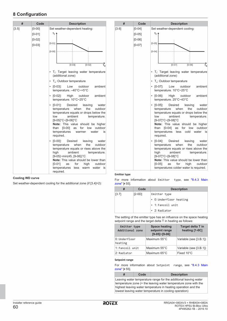
8 Configuration
Installer reference guide
60RRGA04~08DAV3 + RHBX04+08DA
ROTEX HPSU Bi-Bloc Ultra4P495262-1B – 2019.10
# Code Description[3.5] [0-00]
[0-01]
[0-02]
[0-03]
Set weather-dependent heating:
[0-00]
[0-01]
Ta
Tt
[0-03] [0-02]
▪ Tt: Target leaving water temperature(additional zone)
▪ Ta: Outdoor temperature
▪ [0-03]: Low outdoor ambienttemperature. –40°C~+5°C
▪ [0-02]: High outdoor ambienttemperature. 10°C~25°C
▪ [0-01]: Desired leaving watertemperature when the outdoortemperature equals or drops below thelow ambient temperature.[9‑05]°C~[9‑06]°CNote: This value should be higherthan [0‑00] as for low outdoortemperatures warmer water isrequired.
▪ [0-00]: Desired leaving watertemperature when the outdoortemperature equals or rises above thehigh ambient temperature.[9‑05]~min(45, [9‑06])°CNote: This value should be lower than[0‑01] as for high outdoortemperatures less warm water isrequired.
Cooling WD curveSet weather-dependent cooling for the additional zone (if [3.4]=2):
# Code Description[3.6] [0-04]
[0-05]
[0-06]
[0-07]
Set weather-dependent cooling:
[0-04]
[0-05]
Ta
Tt
[0-07] [0-06]
▪ Tt: Target leaving water temperature(additional zone)
▪ Ta: Outdoor temperature
▪ [0-07]: Low outdoor ambienttemperature. 10°C~25°C
▪ [0-06]: High outdoor ambienttemperature. 25°C~43°C
▪ [0-05]: Desired leaving watertemperature when the outdoortemperature equals or drops below thelow ambient temperature.[9‑07]°C~[9‑08]°CNote: This value should be higherthan [0‑04] as for low outdoortemperatures less cold water isrequired.
▪ [0-04]: Desired leaving watertemperature when the outdoortemperature equals or rises above thehigh ambient temperature.[9‑07]°C~[9‑08]°CNote: This value should be lower than[0‑05] as for high outdoortemperatures colder water is required.
Emitter type
For more information about Emitter type, see "8.4.3 Mainzone" [4 55].
# Code Description[3.7] [2‑0D] Emitter type
▪ 0: Underfloor heating
▪ 1: Fancoil unit
▪ 2: Radiator
The setting of the emitter type has an influence on the space heatingsetpoint range and the target delta T in heating as follows:
Emitter typeAdditional zone
Space heatingsetpoint range[9‑05]~[9‑06]
Target delta T inheating [1‑0C]
0: Underfloorheating
Maximum 55°C Variable (see [3.B.1])
1: Fancoil unit Maximum 55°C Variable (see [3.B.1])2: Radiator Maximum 65°C Fixed 10°C
Setpoint range
For more information about Setpoint range, see "8.4.3 Mainzone" [4 55].
# Code DescriptionLeaving water temperature range for the additional leaving watertemperature zone (= the leaving water temperature zone with thehighest leaving water temperature in heating operation and thelowest leaving water temperature in cooling operation)

8 Configuration
Installer reference guide
61RRGA04~08DAV3 + RHBX04+08DAROTEX HPSU Bi-Bloc Ultra4P495262-1B – 2019.10
# Code Description[3.8.1] [9-05] Heating minimum: 15°C~37°C[3.8.2] [9-06] Heating maximum
▪ [2‑0D]=2 (emitter type additional zone= radiator)37°C~60°C
▪ Else: 37°C~55°C[3.8.3] [9-07] Cooling minimum: 5°C~18°C[3.8.4] [9-08] Cooling maximum: 8°C~22°C
# Code DescriptionLeaving water temperature range for the main leaving watertemperature zone (= the leaving water temperature zone with thelowest leaving water temperature in heating operation and thehighest leaving water temperature in cooling operation)[2.8.1] [9-01] Heating minimum:
▪ 15°C~37°C[2.8.2] [9-00] Heating maximum:
▪ [2‑0C]=2 (emitter type main zone =radiator)37°C~70°C
▪ Otherwise: 37°C~55°C[2.8.3] [9-02] Cooling minimum:
▪ 5°C~18°C[2.8.4] [9-03] Cooling maximum:
▪ 18°C~22°C
Control
The control type for the additional zone is read only. It is determinedby the control type of the main zone.
See "8.4.3 Main zone" [4 55].
# Code Description[3.9] N/A Control
▪ Leaving water if the control type ofthe main zone is Leaving water.
▪ External room thermostat if thecontrol type of the main zone is:
▪ External room thermostat,or
▪ Room thermostat.
Thermostat type
Only applicable in external room thermostat control.
Also see "8.4.3 Main zone" [4 55].
# Code Description[3.A] [C‑06] External room thermostat type for the
additional zone:
▪ 1: 1 contact. Connected to only 1digital input (X2M/35a)
▪ 2: 2 contacts. Connected to 2 digitalinputs (X2M/34a and X2M/35a)
Leaving water temperature: Delta T
For more information, see "8.4.3 Main zone" [4 55].
# Code Description[3.B.1] [1-0C] Delta T heating: A minimum
temperature difference is required for thegood operation of heat emitters inheating mode.
▪ If [2-0D] = 2, this is fixed to 10°C
▪ Else: 3°C~10°C[3.B.2] [1-0E] Delta T cooling: A minimum
temperature difference is required for thegood operation of heat emitters incooling mode.
▪ 3°C~10°C
8.4.5 Space heating/coolingAbout space operation modesYour unit can be a heating or a heating/cooling model:
▪ If your unit is a heating model, it can heat up a space.
▪ If your unit is a heating/cooling model, it can both heat up and cooldown a space. You have to tell the system which operation modeto use.
To determine if a heating/cooling heat pump model is installed1 Go to [4]: Space heating/cooling.2 Check if [4.1] Operation mode is listed and editable.
If so, a heating/cooling heat pump model is installed.
To tell the system which space operation to use, you can:
You can… LocationCheck which space operation mode iscurrently used.
Home screen
Set the space operation mode permanently. Main menuRestrict automatic changeover according toa monthly schedule.
To check which space operation mode is currently usedThe space operation mode is displayed on the home screen:
▪ When the unit is in heating mode, the icon is shown.
▪ When the unit is in cooling mode, the icon is shown.
The status indicator shows if the unit is currently in operation:
▪ When the unit is not in operation, the status indicator will show ablue pulsation with an interval of approximately 5 seconds.
▪ While the unit is in operation, the status indicator will light up blueconstantly.
To set the space operation mode1 Go to [4.1]: Space heating/cooling > Operation
mode
2 Select one of the following options:
▪ Heating: Only heating mode
▪ Cooling: Only cooling mode
▪ Automatic: The operation mode changesautomatically based on the outdoor temperature.Restricted according to the operation modeschedule.
Automatic heating/cooling changeover is only applicable for RHBX.
When Automatic is selected, the unit switches its operation mode,based on the Operation mode schedule [4.2]. In this schedule, theend user indicates which operation is allowed for each month.
To restrict automatic changeover according to a scheduleConditions: You set the space operation mode to Automatic.
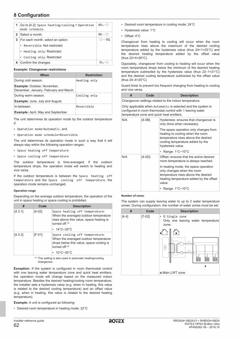
8 Configuration
Installer reference guide
62RRGA04~08DAV3 + RHBX04+08DA
ROTEX HPSU Bi-Bloc Ultra4P495262-1B – 2019.10
1 Go to [4.2]: Space heating/cooling > Operationmode schedule.
2 Select a month.3 For each month, select an option:
▪ Reversible: Not restricted
▪ Heating only: Restricted
▪ Cooling only: Restricted4 Confirm the changes.
Example: Changeover restrictionsWhen Restriction
During cold season.
Example: October, November,December, January, February and March.
Heating only
During warm season.
Example: June, July and August.
Cooling only
In-between.
Example: April, May and September.
Reversible
The unit determines its operation mode by the outdoor temperatureif:
▪ Operation mode=Automatic, and
▪ Operation mode schedule=Reversible.
The unit determines its operation mode in such a way that it willalways stay within the following operation ranges:
▪ Space heating off temperature
▪ Space cooling off temperature
The outdoor temperature is time-averaged. If the outdoortemperature drops, the operation mode will switch to heating andvice versa.
If the outdoor temperature is between the Space heating offtemperature and the Space cooling off temperature, theoperation mode remains unchanged.
Operation range
Depending on the average outdoor temperature, the operation of theunit in space heating or space cooling is prohibited.
# Code Description[4.3.1] [4-02] Space heating off temperature:
When the averaged outdoor temperaturerises above this value, space heating isturned off.(a)
▪ 14°C~35°C[4.3.2] [F-01] Space cooling off temperature:
When the averaged outdoor temperaturedrops below this value, space cooling isturned off.(a)
▪ 10°C~35°C(a) This setting is also used in automatic heating/cooling
changeover.
Exception: If the system is configured in room thermostat controlwith one leaving water temperature zone and quick heat emitters,the operation mode will change based on the measured indoortemperature. Besides the desired heating/cooling room temperature,the installer sets a hysteresis value (e.g. when in heating, this valueis related to the desired cooling temperature) and an offset value(e.g. when in heating, this value is related to the desired heatingtemperature).
Example: A unit is configured as following:
▪ Desired room temperature in heating mode: 22°C
▪ Desired room temperature in cooling mode: 24°C
▪ Hysteresis value: 1°C
▪ Offset: 4°C
Changeover from heating to cooling will occur when the roomtemperature rises above the maximum of the desired coolingtemperature added by the hysteresis value (thus 24+1=25°C) andthe desired heating temperature added by the offset value(thus 22+4=26°C).
Oppositely, changeover from cooling to heating will occur when theroom temperature drops below the minimum of the desired heatingtemperature subtracted by the hysteresis value (thus 22–1=21°C)and the desired cooling temperature subtracted by the offset value(thus 24–4=20°C)
Guard timer to prevent too frequent changing from heating to coolingand vice versa.
# Code DescriptionChangeover settings related to the indoor temperature.
Only applicable when Automatic is selected and the system isconfigured in room thermostat control with 1 leaving watertemperature zone and quick heat emitters.N/A [4-0B] Hysteresis: ensures that changeover is
only done when necessary.
The space operation only changes fromheating to cooling when the roomtemperature rises above the desiredcooling temperature added by thehysteresis value.
▪ Range: 1°C~10°CN/A [4-0D] Offset: ensures that the active desired
room temperature is always reached.
In heating mode, the space operationonly changes when the roomtemperature rises above the desiredheating temperature added by the offsetvalue.
▪ Range: 1°C~10°C
Number of zones
The system can supply leaving water to up to 2 water temperaturezones. During configuration, the number of water zones must be set.
# Code Description[4.4] [7‑02] ▪ 0: Single zone
Only one leaving water temperaturezone:
a
a Main LWT zone

8 Configuration
Installer reference guide
63RRGA04~08DAV3 + RHBX04+08DAROTEX HPSU Bi-Bloc Ultra4P495262-1B – 2019.10
# Code Description[4.4] [7‑02] ▪ 1: Dual zone
Two leaving water temperature zones.The main leaving water temperaturezone consists of the higher load heatemitters and a mixing station toachieve the desired leaving watertemperature. In heating:
a
bc
a Additional LWT zone: Highesttemperature
b Main LWT zone: Lowest temperature
c Mixing station
CAUTIONNOT configuring the system in the following way can causedamage to the heat emitters. If there are 2 zones, it isimportant that in heating:
▪ the zone with the lowest water temperature isconfigured as the main zone, and
▪ the zone with the highest water temperature isconfigured as the additional zone.
CAUTIONIf there are 2 zones and the emitter types are wronglyconfigured, water of high temperature can be sent towardsa low temperature emitter (underfloor heating). To avoidthis:
▪ Install an aquastat/thermostatic valve to avoid too hightemperatures towards a low temperature emitter.
▪ Make sure you set the emitter types for the main zone[2.7] and for the additional zone [3.7] correctly inaccordance with the connected emitter.
Pump operation mode
When the space heating/cooling operation is OFF, the pump isalways OFF. When space heating/cooling operation is ON, you havethe choice between these operation modes:
# Code Description[4.5] [F–0D] Pump operation mode:
▪ 0 Continuous: Continuous pumpoperation, regardless of thermo ON orOFF condition. Remark: Continuouspump operation requires more energythan sample or request pumpoperation.
ab c
db c
a Space heating/cooling control
b Off
c On
d Pump operation[4.5] [F-0D] ▪ 1 Sample: The pump is ON when there
is heating or cooling demand as theleaving water temperature has not yetreached the desired temperature yet.When thermo OFF condition occurs,the pump runs every 3 minutes tocheck the water temperature anddemand heating or cooling ifnecessary. Remark: Sample is ONLYavailable in leaving water temperaturecontrol.ab
d e f
c
gb
c
a Space heating/cooling control
b Off
c On
d LWT temperature
e Actual
f Desired
g Pump operation[4.5] [F-0D] ▪ 2 Request: Pump operation based on
request. Example: Using a roomthermostat and thermostat createsthermo ON/OFF condition. Remark:NOT available in leaving watertemperature control.a
d
e
b
b
c
b c
c
a Space heating/cooling control
b Off
c On
d Heating demand (by external roomthermostat or room thermostat)
e Pump operation
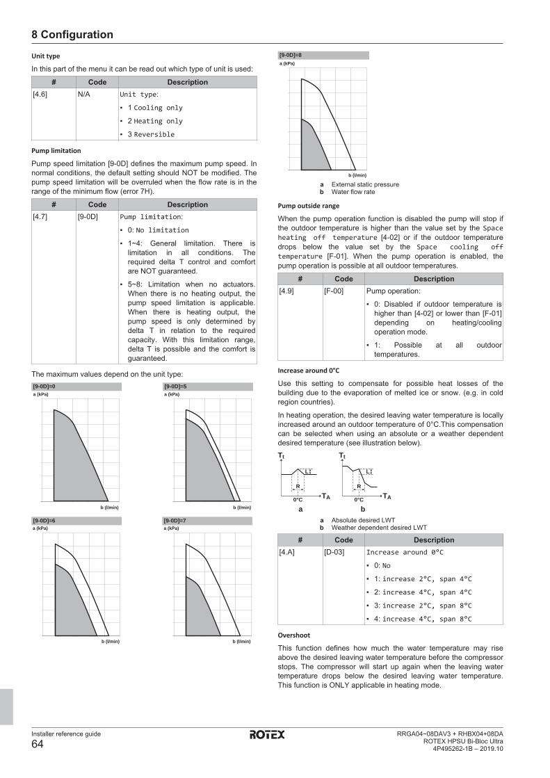
8 Configuration
Installer reference guide
64RRGA04~08DAV3 + RHBX04+08DA
ROTEX HPSU Bi-Bloc Ultra4P495262-1B – 2019.10
Unit type
In this part of the menu it can be read out which type of unit is used:
# Code Description[4.6] N/A Unit type:
▪ 1 Cooling only
▪ 2 Heating only
▪ 3 Reversible
Pump limitation
Pump speed limitation [9‑0D] defines the maximum pump speed. Innormal conditions, the default setting should NOT be modified. Thepump speed limitation will be overruled when the flow rate is in therange of the minimum flow (error 7H).
# Code Description[4.7] [9-0D] Pump limitation:
▪ 0: No limitation
▪ 1~4: General limitation. There islimitation in all conditions. Therequired delta T control and comfortare NOT guaranteed.
▪ 5~8: Limitation when no actuators.When there is no heating output, thepump speed limitation is applicable.When there is heating output, thepump speed is only determined bydelta T in relation to the requiredcapacity. With this limitation range,delta T is possible and the comfort isguaranteed.
The maximum values depend on the unit type:[9-0D]=0 [9-0D]=5a (kPa)
b (l/min)
a (kPa)
b (l/min)
a (kPa)
b (l/min)
a (kPa)
b (l/min)
[9-0D]=6 [9-0D]=7
[9-0D]=8a (kPa)
b (l/min)
a External static pressureb Water flow rate
Pump outside range
When the pump operation function is disabled the pump will stop ifthe outdoor temperature is higher than the value set by the Spaceheating off temperature [4‑02] or if the outdoor temperaturedrops below the value set by the Space cooling offtemperature [F‑01]. When the pump operation is enabled, thepump operation is possible at all outdoor temperatures.
# Code Description[4.9] [F-00] Pump operation:
▪ 0: Disabled if outdoor temperature ishigher than [4‑02] or lower than [F‑01]depending on heating/coolingoperation mode.
▪ 1: Possible at all outdoortemperatures.
Increase around 0°C
Use this setting to compensate for possible heat losses of thebuilding due to the evaporation of melted ice or snow. (e.g. in coldregion countries).
In heating operation, the desired leaving water temperature is locallyincreased around an outdoor temperature of 0°C.This compensationcan be selected when using an absolute or a weather dependentdesired temperature (see illustration below).Tt
TA
R
L
0°C
Tt
TA
R
L
0°C
a ba Absolute desired LWTb Weather dependent desired LWT
# Code Description[4.A] [D-03] Increase around 0°C
▪ 0: No
▪ 1: increase 2°C, span 4°C
▪ 2: increase 4°C, span 4°C
▪ 3: increase 2°C, span 8°C
▪ 4: increase 4°C, span 8°C
Overshoot
This function defines how much the water temperature may riseabove the desired leaving water temperature before the compressorstops. The compressor will start up again when the leaving watertemperature drops below the desired leaving water temperature.This function is ONLY applicable in heating mode.
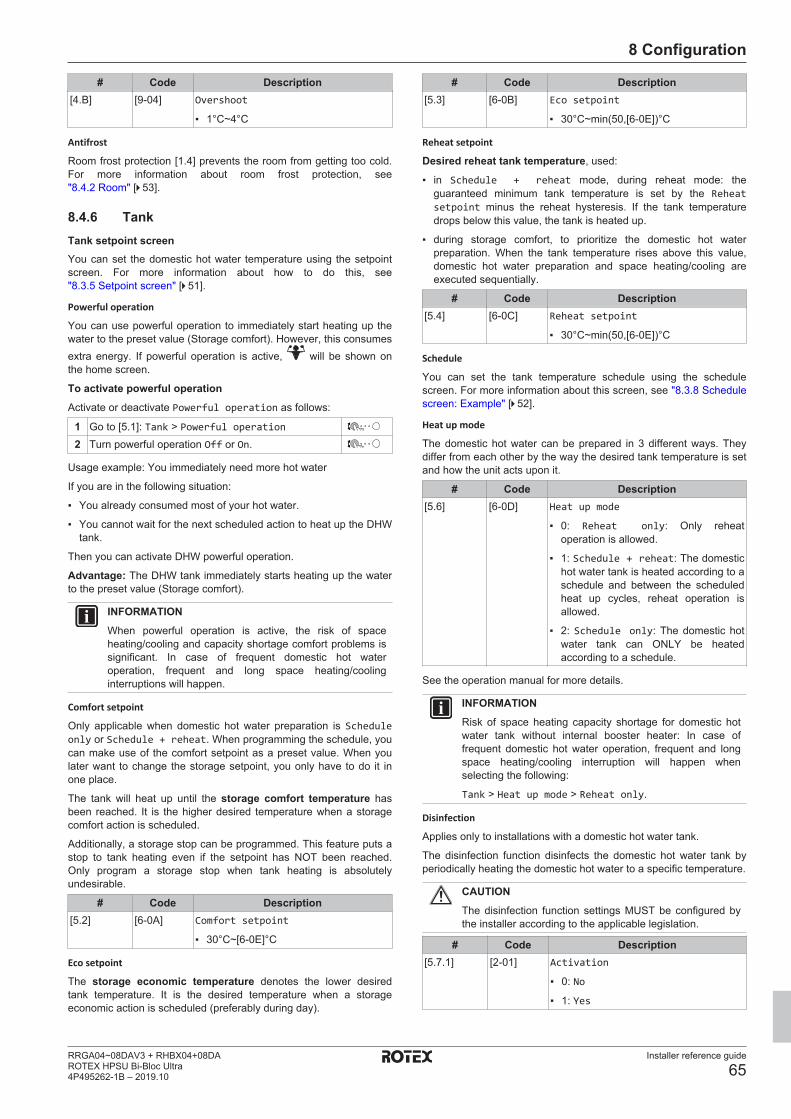
8 Configuration
Installer reference guide
65RRGA04~08DAV3 + RHBX04+08DAROTEX HPSU Bi-Bloc Ultra4P495262-1B – 2019.10
# Code Description[4.B] [9-04] Overshoot
▪ 1°C~4°C
Antifrost
Room frost protection [1.4] prevents the room from getting too cold.For more information about room frost protection, see"8.4.2 Room" [4 53].
8.4.6 TankTank setpoint screenYou can set the domestic hot water temperature using the setpointscreen. For more information about how to do this, see"8.3.5 Setpoint screen" [4 51].
Powerful operation
You can use powerful operation to immediately start heating up thewater to the preset value (Storage comfort). However, this consumesextra energy. If powerful operation is active, will be shown onthe home screen.
To activate powerful operationActivate or deactivate Powerful operation as follows:
1 Go to [5.1]: Tank > Powerful operation2 Turn powerful operation Off or On.
Usage example: You immediately need more hot water
If you are in the following situation:
▪ You already consumed most of your hot water.
▪ You cannot wait for the next scheduled action to heat up the DHWtank.
Then you can activate DHW powerful operation.
Advantage: The DHW tank immediately starts heating up the waterto the preset value (Storage comfort).
INFORMATIONWhen powerful operation is active, the risk of spaceheating/cooling and capacity shortage comfort problems issignificant. In case of frequent domestic hot wateroperation, frequent and long space heating/coolinginterruptions will happen.
Comfort setpoint
Only applicable when domestic hot water preparation is Scheduleonly or Schedule + reheat. When programming the schedule, youcan make use of the comfort setpoint as a preset value. When youlater want to change the storage setpoint, you only have to do it inone place.
The tank will heat up until the storage comfort temperature hasbeen reached. It is the higher desired temperature when a storagecomfort action is scheduled.
Additionally, a storage stop can be programmed. This feature puts astop to tank heating even if the setpoint has NOT been reached.Only program a storage stop when tank heating is absolutelyundesirable.
# Code Description[5.2] [6-0A] Comfort setpoint
▪ 30°C~[6‑0E]°C
Eco setpoint
The storage economic temperature denotes the lower desiredtank temperature. It is the desired temperature when a storageeconomic action is scheduled (preferably during day).
# Code Description[5.3] [6-0B] Eco setpoint
▪ 30°C~min(50,[6‑0E])°C
Reheat setpoint
Desired reheat tank temperature, used:
▪ in Schedule + reheat mode, during reheat mode: theguaranteed minimum tank temperature is set by the Reheatsetpoint minus the reheat hysteresis. If the tank temperaturedrops below this value, the tank is heated up.
▪ during storage comfort, to prioritize the domestic hot waterpreparation. When the tank temperature rises above this value,domestic hot water preparation and space heating/cooling areexecuted sequentially.
# Code Description[5.4] [6-0C] Reheat setpoint
▪ 30°C~min(50,[6‑0E])°C
Schedule
You can set the tank temperature schedule using the schedulescreen. For more information about this screen, see "8.3.8 Schedulescreen: Example" [4 52].
Heat up mode
The domestic hot water can be prepared in 3 different ways. Theydiffer from each other by the way the desired tank temperature is setand how the unit acts upon it.
# Code Description[5.6] [6-0D] Heat up mode
▪ 0: Reheat only: Only reheatoperation is allowed.
▪ 1: Schedule + reheat: The domestichot water tank is heated according to aschedule and between the scheduledheat up cycles, reheat operation isallowed.
▪ 2: Schedule only: The domestic hotwater tank can ONLY be heatedaccording to a schedule.
See the operation manual for more details.
INFORMATIONRisk of space heating capacity shortage for domestic hotwater tank without internal booster heater: In case offrequent domestic hot water operation, frequent and longspace heating/cooling interruption will happen whenselecting the following:
Tank > Heat up mode > Reheat only.
Disinfection
Applies only to installations with a domestic hot water tank.
The disinfection function disinfects the domestic hot water tank byperiodically heating the domestic hot water to a specific temperature.
CAUTIONThe disinfection function settings MUST be configured bythe installer according to the applicable legislation.
# Code Description[5.7.1] [2‑01] Activation
▪ 0: No
▪ 1: Yes
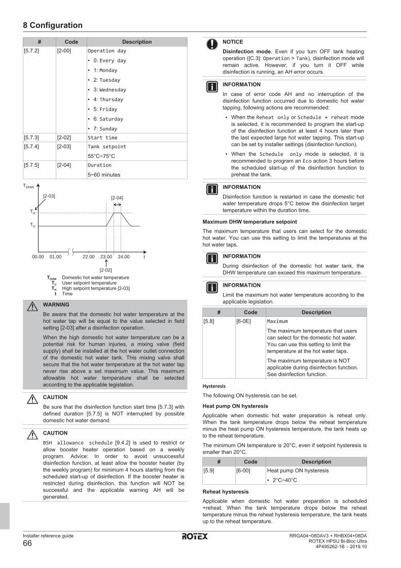
8 Configuration
Installer reference guide
66RRGA04~08DAV3 + RHBX04+08DA
ROTEX HPSU Bi-Bloc Ultra4P495262-1B – 2019.10
# Code Description[5.7.2] [2‑00] Operation day
▪ 0: Every day
▪ 1: Monday
▪ 2: Tuesday
▪ 3: Wednesday
▪ 4: Thursday
▪ 5: Friday
▪ 6: Saturday
▪ 7: Sunday[5.7.3] [2‑02] Start time
[5.7.4] [2‑03] Tank setpoint
55°C~75°C[5.7.5] [2‑04] Duration
5~60 minutes
00.00 22.00 24.0001.00 23.00 t
TDHW
TH
TU
[2-02]
[2-03] [2-04]
TDHW Domestic hot water temperatureTU User setpoint temperatureTH High setpoint temperature [2-03]
t Time
WARNINGBe aware that the domestic hot water temperature at thehot water tap will be equal to the value selected in fieldsetting [2-03] after a disinfection operation.
When the high domestic hot water temperature can be apotential risk for human injuries, a mixing valve (fieldsupply) shall be installed at the hot water outlet connectionof the domestic hot water tank. This mixing valve shallsecure that the hot water temperature at the hot water tapnever rise above a set maximum value. This maximumallowable hot water temperature shall be selectedaccording to the applicable legislation.
CAUTIONBe sure that the disinfection function start time [5.7.3] withdefined duration [5.7.5] is NOT interrupted by possibledomestic hot water demand.
CAUTIONBSH allowance schedule [9.4.2] is used to restrict orallow booster heater operation based on a weeklyprogram. Advice: In order to avoid unsuccessfuldisinfection function, at least allow the booster heater (bythe weekly program) for minimum 4 hours starting from thescheduled start-up of disinfection. If the booster heater isrestricted during disinfection, this function will NOT besuccessful and the applicable warning AH will begenerated.
NOTICEDisinfection mode. Even if you turn OFF tank heatingoperation ([C.3]: Operation > Tank), disinfection mode willremain active. However, if you turn it OFF whiledisinfection is running, an AH error occurs.
INFORMATIONIn case of error code AH and no interruption of thedisinfection function occurred due to domestic hot watertapping, following actions are recommended:
▪ When the Reheat only or Schedule + reheat modeis selected, it is recommended to program the start-upof the disinfection function at least 4 hours later thanthe last expected large hot water tapping. This start-upcan be set by installer settings (disinfection function).
▪ When the Schedule only mode is selected, it isrecommended to program an Eco action 3 hours beforethe scheduled start-up of the disinfection function topreheat the tank.
INFORMATIONDisinfection function is restarted in case the domestic hotwater temperature drops 5°C below the disinfection targettemperature within the duration time.
Maximum DHW temperature setpointThe maximum temperature that users can select for the domestichot water. You can use this setting to limit the temperatures at thehot water taps.
INFORMATIONDuring disinfection of the domestic hot water tank, theDHW temperature can exceed this maximum temperature.
INFORMATIONLimit the maximum hot water temperature according to theapplicable legislation.
# Code Description[5.8] [6-0E] Maximum
The maximum temperature that userscan select for the domestic hot water.You can use this setting to limit thetemperature at the hot water taps.
The maximum temperature is NOTapplicable during disinfection function.See disinfection function.
Hysteresis
The following ON hysteresis can be set.
Heat pump ON hysteresisApplicable when domestic hot water preparation is reheat only.When the tank temperature drops below the reheat temperatureminus the heat pump ON hysteresis temperature, the tank heats upto the reheat temperature.
The minimum ON temperature is 20°C, even if setpoint hysteresis issmaller than 20°C.
# Code Description[5.9] [6-00] Heat pump ON hysteresis
▪ 2°C~40°C
Reheat hysteresisApplicable when domestic hot water preparation is scheduled+reheat. When the tank temperature drops below the reheattemperature minus the reheat hysteresis temperature, the tank heatsup to the reheat temperature.
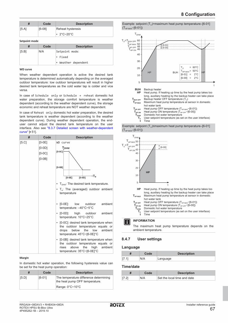
8 Configuration
Installer reference guide
67RRGA04~08DAV3 + RHBX04+08DAROTEX HPSU Bi-Bloc Ultra4P495262-1B – 2019.10
# Code Description[5.A] [6-08] Reheat hysteresis
▪ 2°C~20°C
Setpoint mode
# Code Description[5.B] N/A Setpoint mode:
▪ Fixed
▪ Weather dependent
WD curve
When weather dependent operation is active the desired tanktemperature is determined automatically depending on the averagedoutdoor temperature: low outdoor temperatures will result in higherdesired tank temperatures as the cold water tap is colder and viceversa.
In case of Schedule only or Schedule + reheat domestic hotwater preparation, the storage comfort temperature is weatherdependent (according to the weather dependent curve), the storageeconomic and reheat temperature are NOT weather dependent.
In case of Reheat only domestic hot water preparation, the desiredtank temperature is weather dependent (according to the weatherdependent curve). During weather dependent operation, the end-user cannot adjust the desired tank temperature on the userinterface. Also see "8.3.7 Detailed screen with weather-dependentcurve" [4 51].
# Code Description[5.C] [0-0E]
[0-0D]
[0-0C]
[0-0B]
WD curve
TDHW
Ta
[0-0C]
[0-0B]
[0-0E] [0-0D]
▪ TDHW: The desired tank temperature.
▪ Ta: The (averaged) outdoor ambienttemperature
▪ [0-0E]: low outdoor ambienttemperature: –40°C~5°C
▪ [0-0D]: high outdoor ambienttemperature: 10°C~25°C
▪ [0-0C]: desired tank temperature whenthe outdoor temperature equals ordrops below the low ambienttemperature: 45°C~[6‑0E]°C
▪ [0-0B]: desired tank temperature whenthe outdoor temperature equals orrises above the high ambienttemperature: 35°C~[6‑0E]°C
Margin
In domestic hot water operation, the following hysteresis value canbe set for the heat pump operation:
# Code Description[5.D] [6-01] The temperature difference determining
the heat pump OFF temperature.
Range: 0°C~10°C
Example: setpoint (TU)>maximum heat pump temperature–[6‑01](THP MAX–[6‑01])
t
TDHW
THP ON
THP OFF
THP MAX
TU=TBUH OFF
[6-01][6-00]
TU = 60°CTHP MAX= 50°C[6-01] = 2°C[6-00] = 2°C
HP BUH HP
5
10
20
30
40
46485060
BUH Backup heaterHP Heat pump. If heating up time by the heat pump takes too
long, auxiliary heating by the backup heater can take placeTBUH OFF Backup heater OFF temperature (TU)THP MAX Maximum heat pump temperature at sensor in domestic
hot water tankTHP OFF Heat pump OFF temperature (THP MAX−[6-01])THP ON Heat pump ON temperature (THP OFF−[6-00])TDHW Domestic hot water temperature
TU User setpoint temperature (as set on the user interface)t Time
Example: setpoint (TU)≤maximum heat pump temperature–[6‑01](THP MAX–[6‑01])
t
[6-00]
HP
5
10
20
30
4043
45TU=THP OFF
THP MAX
TDHW
THP ON
50
HP Heat pump. If heating up time by the heat pump takes toolong, auxiliary heating by the backup heater can take place
THP MAX Maximum heat pump temperature at sensor in domestichot water tank
THP OFF Heat pump OFF temperature (THP MAX−[6-01])THP ON Heat pump ON temperature (THP OFF−[6-00])TDHW Domestic hot water temperature
TU User setpoint temperature (as set on the user interface)t Time
INFORMATIONThe maximum heat pump temperature depends on theambient temperature.
8.4.7 User settings
Language# Code Description
[7.1] N/A Language
Time/date# Code Description
[7.2] N/A Set the local time and date

8 Configuration
Installer reference guide
68RRGA04~08DAV3 + RHBX04+08DA
ROTEX HPSU Bi-Bloc Ultra4P495262-1B – 2019.10
INFORMATIONBy default, daylight savings time is enabled and clockformat is set to 24 hours. If you want to change thesesettings, you can do this in the menu structure (Usersettings > Time/date) once the unit is initialised.
HolidayAbout holiday mode
During your holiday, you can use the holiday mode to deviate fromyour normal schedules without having to change them. While holidaymode is active, space heating/cooling operation and domestic hotwater operation will be turned off. Room frost protection and anti-legionella operation will remain active.
Typical workflowUsing holiday mode typically consists of the following stages:1 Setting the starting date and ending date of your holiday.2 Activating the holiday mode.
To check if holiday mode is activated and/or running
If is displayed on the home screen, holiday mode is active.
To configure the holiday
1 Activate the holiday mode. —▪ Go to [7.3.1]: User settings > Holiday >Activation.
Activation
Till
7.3.1
From
▪ Select On.2 Set the first day of your holiday. —
▪ Go to [7.3.2]: From.▪ Select a date.
▪ Confirm the changes.3 Set the last day of your holiday. —
▪ Go to [7.3.3]: Till.▪ Select a date.
▪ Confirm the changes.
QuietAbout quiet mode
You can use quiet mode to decrease the sound of the outdoor unit.However, this also decreases the heating/cooling capacity of thesystem. There are multiple quiet mode levels.
You can:
▪ Completely deactivate quiet mode
▪ Manually activate a quiet mode level until the next scheduledaction
▪ Use and program a quiet mode schedule
INFORMATIONIf the outdoor temperature is below zero, we recommend toNOT use the most quiet level.
To check if quiet mode is active
If is displayed on the home screen, quiet mode is active.
To use quiet mode
1 Go to [7.4.1]: User settings > Quiet >Activation.
2 Do one of the following: —
If you want to… Then…Completely deactivatequiet mode
Select Off.
Manually activate a quietmode level
Select the applicable quietmode level. Example: Mostquiet.
Use and program a quietmode schedule
Select Automatic.Go to [7.4.2] Schedule andprogram the schedule. Formore information aboutscheduling, see"8.3.8 Schedule screen:Example" [4 52].
Usage example: Baby is sleeping in the afternoon
If you are in the following situation:
▪ You have programmed a quiet mode schedule:
▪ During the night: Most quiet.
▪ During the day: Off to ensure the heating/cooling capacity ofthe system.
▪ However, during the afternoon the baby is sleeping and you wantit to be quiet.
Then you can do the following:
1 Go to [7.4.1]: User settings > Quiet >Activation.
2 Select Most quiet.
Advantage:
The outdoor unit runs in its most quiet level.
Electricity prices and gas priceOnly applicable in combination with the bivalent function. See also"Bivalent" [4 75].
# Code Description[7.5.1] N/A Electricity price > High[7.5.2] N/A Electricity price > Medium[7.5.3] N/A Electricity price > Low[7.6] N/A Gas price
INFORMATIONElectricity price can only be set when bivalent is ON([9.C.1] or [C-02]). These values can only be set in menustructure [7.5.1], [7.5.2] and [7.5.3]. Do NOT use overviewsettings.
To set the gas price
1 Go to [7.6]: User settings > Gas price.2 Select the correct gas price.3 Confirm the changes.
INFORMATIONPrice value ranging from 0.00~990 valuta/kWh (with 2significant values).
To set the electricity price
1 Go to [7.5.1]/[7.5.2]/[7.5.3]: User settings >Electricity price > High/Medium/Low.

8 Configuration
Installer reference guide
69RRGA04~08DAV3 + RHBX04+08DAROTEX HPSU Bi-Bloc Ultra4P495262-1B – 2019.10
2 Select the correct electricity price.3 Confirm the changes.4 Repeat this for all three electricity prices. —
INFORMATIONPrice value ranging from 0.00~990 valuta/kWh (with 2significant values).
INFORMATIONIf no schedule is set, the Electricity price for High istaken into account.
To set the electricity price schedule timer
1 Go to [7.5.4]: User settings > Electricityprice > Schedule.
2 Program the selection using the scheduling screen.You can set the High, Medium and Low electricityprices according to your electricity supplier.
—
3 Confirm the changes.
INFORMATIONThe values correspond with the electricity price values forHigh, Medium and Low previously set. If no schedule is set,the electricity price for High is taken into account.
About energy prices in case of an incentive per kWh renewableenergy
An incentive can be taken into account when setting the energyprices. Although the running cost can increase, the total operationcost, taking into account the reimbursement will be optimized.
NOTICEMake sure to modify the setting of the energy prices at theend of the incentive period.
To set the gas price in case of an incentive per kWh renewableenergy
Calculate the value for the gas price with the following formula:
▪ Actual gas price+(Incentive/kWh×0.9)
For the procedure to set the gas price, see "To set the gasprice" [4 68].
To set the electricity price in case of an incentive per kWhrenewable energy
Calculate the value for the electricity price with following formula:
▪ Actual electricity price+Incentive/kWh
For the procedure to set the electricity price, see "To set theelectricity price" [4 68].
Example
This is an example and the prices and/or values used in thisexample are NOT accurate.
Data Price/kWhGas price 4.08Electricity price 12.49Renewable heat incentive perkWh
5
Calculation of the gas price:Gas price=Actual gas price+(Incentive/kWh×0.9)
Gas price=4.08+(5×0.9)
Gas price=8.58
Calculation of the electricity price:Electricity price=Actual electricity price+Incentive/kWh
Electricity price=12.49+5
Electricity price=17.49
Price Value in breadcrumbGas: 4.08 /kWh [7.6]=8.6Electricity: 12.49 /kWh [7.5.1]=17
8.4.8 InformationDealer information
The installer can fill in his contact number here.
# Code Description[8.3] N/A Number that users can call in case of
problems.
Possible read-out informationIn menu… You can read out…
[8.1] Energy data Produced energy, consumedelectricity, and consumed gas
[8.2] Malfunction history Malfunction history[8.3] Dealer information Contact/helpdesk number[8.4] Sensors Room, tank or domestic hot
water, outside, and leaving watertemperature (if applicable)
[8.5] Actuators Status/mode of each actuator
Example: Domestic hot waterpump ON/OFF
[8.6] Operation modes Current operation mode
Example: Defrost/oil returnmode
[8.7] About Version information about thesystem
[8.8] Connection status Information about the connectionstatus of the unit, the roomthermostat and the LAN adapter.
8.4.9 Installer settings
Configuration wizardAfter first power ON of the system, the user interface will guide youusing the configuration wizard. This way you can set the mostimportant initial settings. This way the unit will be able to runproperly. Afterwards, more detailed settings can be done via themenu structure if required.
To restart the configuration wizard, go to Installer settings >Configuration wizard [9.1].
Domestic hot waterThis part only applies to systems with an optional domestic hot watertank installed.
Domestic hot water
The following setting determines if the system can prepare domestichot water or not, and which tank is used. Set this setting according tothe actual installation.
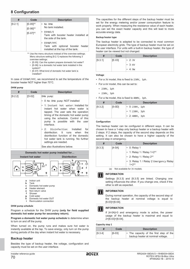
8 Configuration
Installer reference guide
70RRGA04~08DAV3 + RHBX04+08DA
ROTEX HPSU Bi-Bloc Ultra4P495262-1B – 2019.10
# Code Description[9.2.1] [E‑05](a)
[E‑06](a)
[E‑07](a)
▪ No DHWNo tank installed.
▪ EKHWS/ETank with booster heater installed atthe side of the tank.
▪ EKHWP/HYCTank with optional booster heaterinstalled at the top of the tank.
(a) Use the menu structure instead of the overview settings.Menu structure setting [9.2.1] replaces the following 3overview settings:• [E-05]: Can the system prepare domestic hot water?• [E-06]: Is a domestic hot water tank installed in the
system?• [E-07]: What kind of domestic hot water tank is
installed?
In case of EKHWP/HYC, we recommend to set the temperature of thebooster heater NOT higher than 70°C.
DHW pump
# Code Description[9.2.2] [D‑02] DHW pump:
▪ 0: No DHW pump: NOT installed
▪ 1: Instant hot water: Installed forinstant hot water when water istapped. The user sets the operationtiming of the domestic hot water pumpusing the schedule. Control of thispump is possible with the userinterface.
▪ 2: Disinfection: Installed fordisinfection. It runs when thedisinfection function of the domestichot water tank is running. No furthersettings are needed.
See also illustrations below.
Domestic hot water pump installed for…Instant hot water Disinfection
fab
g
h
i cc
ab
d f
e g
h
i
a Indoor unitb Tankc Domestic hot water pumpd Heater elemente Non‑return valvef Showerg Cold waterh Domestic hot water OUTi Recirculation connection
DHW pump schedule
Program a schedule for the DHW pump (only for field supplieddomestic hot water pump for secondary return).Program a domestic hot water pump schedule to determine whento turn on and off the pump.
When turned on, the pump runs and makes sure hot water isinstantly available at the tap. To save energy, only turn on the pumpduring periods of the day when instant hot water is necessary.
Backup heaterBesides the type of backup heater, the voltage, configuration andcapacity must be set on the user interface.
The capacities for the different steps of the backup heater must beset for the energy metering and/or power consumption feature towork properly. When measuring the resistance value of each heater,you can set the exact heater capacity and this will lead to moreaccurate energy data.
Backup heater type
The backup heater is adapted to be connected to most commonEuropean electricity grids. The type of backup heater must be set onthe user interface. For units with a built-in backup heater, the type ofheater can be viewed but not changed.
# Code Description[9.3.1] [E‑03] ▪ 2: 3V
▪ 3: 6V
▪ 4: 9W
Voltage
▪ For a 3V model, this is fixed to 230V, 1ph.
▪ For a 6V model, this can be set to:
▪ 230V, 1ph
▪ 230V, 3ph
▪ For a 9W model, this is fixed to 400V, 3ph.
# Code Description[9.3.2] [5‑0D] ▪ 0: 230V, 1ph
▪ 1: 230V, 3ph
▪ 2: 400V, 3ph
Configuration
The backup heater can be configured in different ways. It can bechosen to have a 1-step only backup heater or a backup heater with2 steps. If 2 steps, the capacity of the second step depends on thissetting. It can also be chosen to have a higher capacity of thesecond step in emergency.
# Code Description[9.3.3] [4‑0A] ▪ 0: Relay 1
▪ 1: Relay 1 / Relay 1+2(a)
▪ 2: Relay 1 / Relay 2(a)
▪ 3: Relay 1 / Relay 2 Emergency Relay1+2(a)
(a) Not available for 3V models.
INFORMATIONSettings [9.3.3] and [9.3.5] are linked. Changing onesetting influences the other. If you change one, check if theother is still as expected.
INFORMATIONDuring normal operation, the capacity of the second step ofthe backup heater at nominal voltage is equal to[6‑03]+[6‑04].
INFORMATIONIf [4‑0A]=3 and emergency mode is active, the powerusage of the backup heater is maximal and equal to2×[6‑03]+[6‑04].
Capacity step 1
# Code Description[9.3.4] [6‑03] ▪ The capacity of the first step of the
backup heater at nominal voltage.
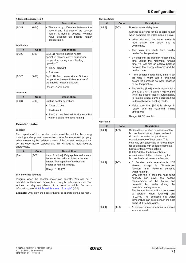
8 Configuration
Installer reference guide
71RRGA04~08DAV3 + RHBX04+08DAROTEX HPSU Bi-Bloc Ultra4P495262-1B – 2019.10
Additional capacity step 2
# Code Description[9.3.5] [6‑04] ▪ The capacity difference between the
second and first step of the backupheater at nominal voltage. Nominalvalue depends on backup heaterconfiguration.
Equilibrium
# Code Description[9.3.6] [5-00] Equilibrium: Is backup heater
operation allowed above equilibriumtemperature during space heatingoperation?
▪ 1: NOT allowed
▪ 0: Allowed[9.3.7] [5-01] Equilibrium temperature: Outdoor
temperature below which operation ofthe backup heater is allowed.
Range: –15°C~35°C
Operation
# Code Description[9.3.8] [4‑00] Backup heater operation:
▪ 0: Restricted
▪ 1: Allowed
▪ 2: Only DHW Enabled for domestic hotwater, disable for space heating
Booster heaterCapacity
The capacity of the booster heater must be set for the energymetering and/or power consumption control feature to work properly.When measuring the resistance value of the booster heater, you canset the exact heater capacity and this will lead to more accurateenergy data.
# Code Description[9.4.1] [6‑02] Capacity [kW]. Only applies to domestic
hot water tank with an internal boosterheater. The capacity of the boosterheater at nominal voltage.
Range: 0~10 kW
BSH allowance schedule
Program when the booster heater can operate. You can set aschedule for the booster heater here using the schedule screen. Twoactions per day are allowed in a week schedule. For moreinformation, see "8.3.8 Schedule screen: Example" [4 52].
Example: Only allow the booster heater to operate during the night.
BSH eco timer
# Code Description[9.4.3] [8-03] Booster heater delay timer.
Start-up delay time for the booster heaterwhen domestic hot water mode is active.
▪ When domestic hot water mode isNOT active, the delay time is20 minutes.
▪ The delay time starts from boosterheater ON temperature.
▪ By adapting the booster heater delaytime versus the maximum runningtime, you can find an optimal balancebetween the energy efficiency and theheat up time.
▪ If the booster heater delay time is settoo high, it might take a long timebefore the domestic hot water reachesits set temperature.
▪ The setting [8‑03] is only meaningful ifsetting [4‑03]=1. Setting [4‑03]=0/2/3/4limits the booster heater automaticallyin relation to heat pump operation timein domestic water heating mode.
▪ Make sure that [8‑03] is always inrelation with the maximum runningtime [8‑01].
Range: 20~95 minutes
Operation
# Code Description[9.4.4] [4-03] Defines the operation permission of the
booster heater depending on ambient,domestic hot water temperature oroperation mode of heat pump. Thissetting is only applicable in reheat modefor applications with separate domestichot water tank. When setting[4‑03]=1/2/3/4, the booster heateroperation can still be restricted by thebooster heater allowance schedule.
[9.4.4] [4-03] ▪ 0: Booster heater operation is NOTallowed except for "Disinfectionfunction" and "Powerful domesticwater heating".Only use this in case the heat pumpcapacity can cover the heatingrequirements of the house anddomestic hot water during thecomplete heating season.The booster heater will not be allowedto operate when Ta<[5‑03] and[5‑02]=1. The domestic hot watertemperature can be maximum the heatpump OFF temperature.
[9.4.4] [4-03] ▪ 1: Booster heater operation is allowedwhen required.

8 Configuration
Installer reference guide
72RRGA04~08DAV3 + RHBX04+08DA
ROTEX HPSU Bi-Bloc Ultra4P495262-1B – 2019.10
# Code Description[9.4.4] [4-03] ▪ 2: The booster heater is allowed
outside the operation range of the heatpump for domestic hot wateroperation.Booster heater operation is onlyallowed if:
▪ Ambient temperature is out of theoperating range: Ta<[5‑03] orTa>35°C
The booster heater is only allowedto operate when Ta<[5‑03] if spaceheating priority is enabled([5‑02]=1).
▪ Domestic hot water temperature is2°C lower than the heat pump OFFtemperature.
If bivalent operation is enabled([C‑02]=1) and permission signal forauxiliary boiler is ON, the booster heaterwill be restricted even when Ta<[5‑03].
9.4.4 [4-03] ▪ 3: The booster heater is allowed whenthe heat pump is NOT active indomestic hot water operation.Same as setting 1, but simultaneousheat pump domestic hot wateroperation and booster heateroperation is not allowed.
9.4.4 [4-03] ▪ 4: Booster heater operation is NOTallowed except for "Disinfectionfunction".Only use this in case the capacity ofthe heat pump can cover the heatingrequirements of the house anddomestic hot water over the completeheating season.The booster heater will not be allowedto operate when Ta<[5‑03] and[5‑02]=1. The domestic hot watertemperature can be maximum the heatpump OFF temperature.
EmergencyEmergency
When the heat pump fails to operate, the backup heater and/orbooster heater can serve as an emergency heater and take over theheat load either automatically or by manual interaction.
▪ When Emergency is set to Automatic and a heat pump failureoccurs:
▪ the backup heater automatically takes over the heat load,
▪ the booster heater in the optional tank automatically takes overthe domestic hot water production.
▪ When Emergency is set to Manual and a heat pump failureoccurs, the domestic hot water and space heating operation stops.To manually recover it via the user interface, go to theMalfunctioning main menu screen and confirm whether thebackup heater and/or booster heater can take over the heat loador not.
We recommend to set Emergency to Automatic if the house isunattended for longer periods.
# Code Description[9.5] N/A ▪ 0: Manual
▪ 1: Automatic
INFORMATIONThe auto emergency setting can be set in the menustructure of the user interface only.
INFORMATIONIf [4‑03]=1 or 3, then Emergency = Manual is not applicablefor the booster heater.
INFORMATIONIf a heat pump failure occurs and Emergency is set toManual, the room frost protection function, the underfloorheating screed dryout function, and the water pipeantifreeze function will remain active even if the user doesNOT confirm emergency operation.
BalancingPrioritiesFor systems with a separate domestic hot water tank
# Code Description[9.6.1] [5-02] Space heating priority: Defines
whether domestic hot water is made bybooster heater only when outdoortemperature is below space heatingpriority temperature. It is recommendedto enable this function to shorten tankheating operation time and guaranteeddomestic hot water comfort.
▪ 0: Off
▪ 1: On
[5‑01] Equilibrium temperature and[5‑03] Space heating prioritytemperature are related to backupheater. So, you must set [5‑03] equal ora few degrees higher than [5‑01].
[9.6.2] [5-03] Priority temperature: Defines theoutdoor temperature which below thedomestic hot water will be heated bybooster heater only.
Range: –15°C~35°C[9.6.3] [5-04] Offset BSH setpoint: Setpoint
correction for domestic hot watertemperature: setpoint correction for thedesired domestic hot watertemperature, to be applied at lowoutdoor temperature when spaceheating priority is enabled. Thecorrected (higher) setpoint will makesure that the total heat capacity of thewater in the tank remainsapproximately unchanged, bycompensating for the colder bottomwater layer of the tank (because theheat exchanger coil is not operational)with a warmer top layer.
Range: 0°C~20°C
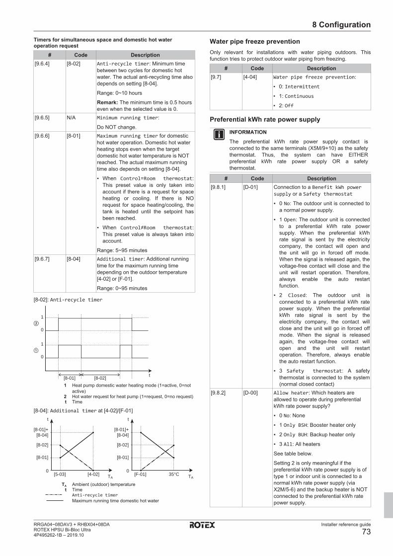
8 Configuration
Installer reference guide
73RRGA04~08DAV3 + RHBX04+08DAROTEX HPSU Bi-Bloc Ultra4P495262-1B – 2019.10
Timers for simultaneous space and domestic hot wateroperation request
# Code Description[9.6.4] [8-02] Anti-recycle timer: Minimum time
between two cycles for domestic hotwater. The actual anti-recycling time alsodepends on setting [8-04].
Range: 0~10 hours
Remark: The minimum time is 0.5 hourseven when the selected value is 0.
[9.6.5] N/A Minimum running timer:
Do NOT change.[9.6.6] [8-01] Maximum running timer for domestic
hot water operation. Domestic hot waterheating stops even when the targetdomestic hot water temperature is NOTreached. The actual maximum runningtime also depends on setting [8-04].
▪ When Control=Room thermostat:This preset value is only taken intoaccount if there is a request for spaceheating or cooling. If there is NOrequest for space heating/cooling, thetank is heated until the setpoint hasbeen reached.
▪ When Control≠Room thermostat:This preset value is always taken intoaccount.
Range: 5~95 minutes[9.6.7] [8-04] Additional timer: Additional running
time for the maximum running timedepending on the outdoor temperature[4-02] or [F-01].
Range: 0~95 minutes
[8-02]: Anti-recycle timer
t
1
0
1
0
[8-01] [8-02]1 Heat pump domestic water heating mode (1=active, 0=not
active)2 Hot water request for heat pump (1=request, 0=no request)t Time
[8-04]: Additional timer at [4-02]/[F-01]t
TA
t
TA
0
[8-01]
[5-03] [4-02]
[8-02]
[8-01]+[8-04]
0
[8-01]
[F-01] 35°C
[8-02]
[8-01]+[8-04]
TA Ambient (outdoor) temperaturet Time
Anti-recycle timerMaximum running time domestic hot water
Water pipe freeze preventionOnly relevant for installations with water piping outdoors. Thisfunction tries to protect outdoor water piping from freezing.
# Code Description[9.7] [4-04] Water pipe freeze prevention:
▪ 0: Intermittent
▪ 1: Continuous
▪ 2: Off
Preferential kWh rate power supply
INFORMATIONThe preferential kWh rate power supply contact isconnected to the same terminals (X5M/9+10) as the safetythermostat. Thus, the system can have EITHERpreferential kWh rate power supply OR a safetythermostat.
# Code Description[9.8.1] [D-01] Connection to a Benefit kWh power
supply or a Safety thermostat
▪ 0 No: The outdoor unit is connected toa normal power supply.
▪ 1 Open: The outdoor unit is connectedto a preferential kWh rate powersupply. When the preferential kWhrate signal is sent by the electricitycompany, the contact will open andthe unit will go in forced off mode.When the signal is released again, thevoltage-free contact will close and theunit will restart operation. Therefore,always enable the auto restartfunction.
▪ 2 Closed: The outdoor unit isconnected to a preferential kWh ratepower supply. When the preferentialkWh rate signal is sent by theelectricity company, the contact willclose and the unit will go in forced offmode. When the signal is releasedagain, the voltage-free contact willopen and the unit will restartoperation. Therefore, always enablethe auto restart function.
▪ 3 Safety thermostat: A safetythermostat is connected to the system(normal closed contact)
[9.8.2] [D-00] Allow heater: Which heaters areallowed to operate during preferentialkWh rate power supply?
▪ 0 No: None
▪ 1 Only BSH: Booster heater only
▪ 2 Only BUH: Backup heater only
▪ 3 All: All heaters
See table below.
Setting 2 is only meaningful if thepreferential kWh rate power supply is oftype 1 or indoor unit is connected to anormal kWh rate power supply (viaX2M/5‑6) and the backup heater is NOTconnected to the preferential kWh ratepower supply.
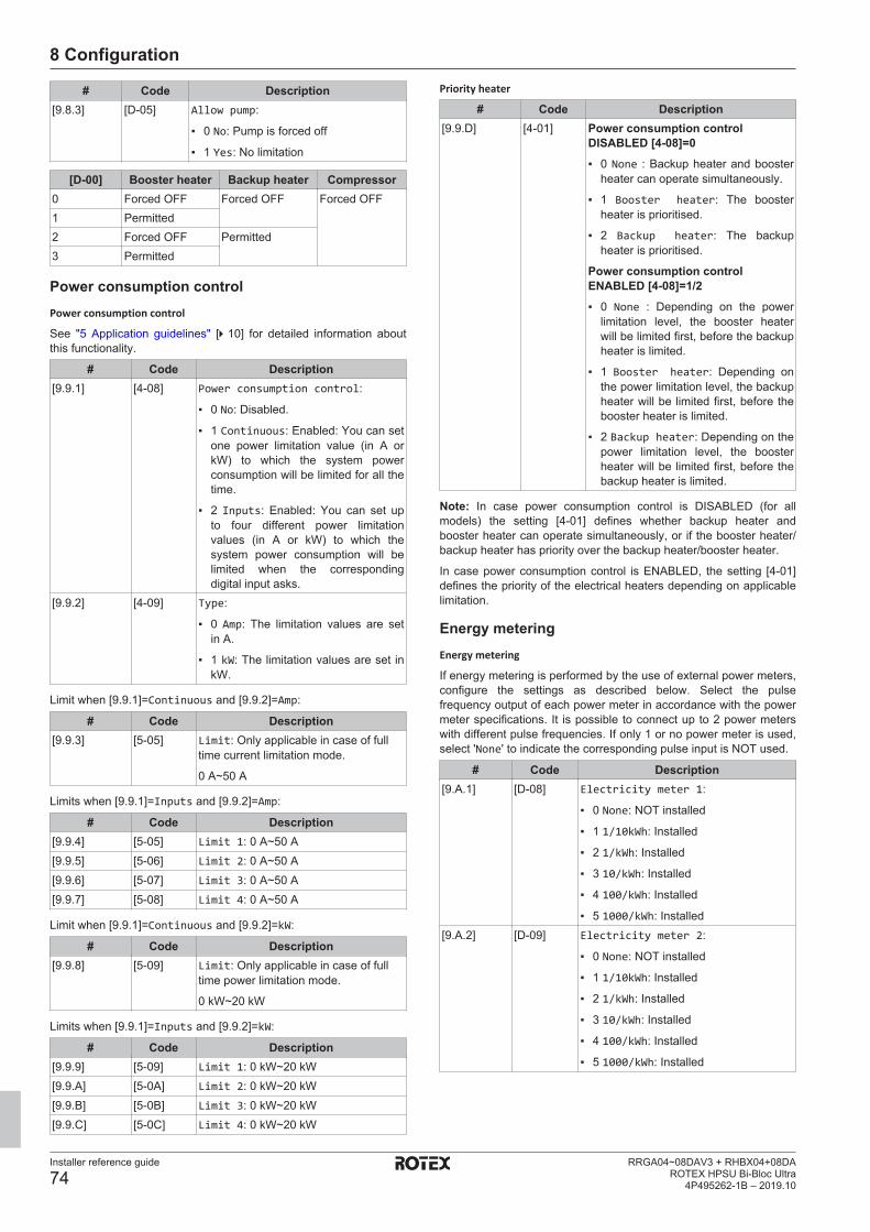
8 Configuration
Installer reference guide
74RRGA04~08DAV3 + RHBX04+08DA
ROTEX HPSU Bi-Bloc Ultra4P495262-1B – 2019.10
# Code Description[9.8.3] [D-05] Allow pump:
▪ 0 No: Pump is forced off
▪ 1 Yes: No limitation
[D‑00] Booster heater Backup heater Compressor0 Forced OFF Forced OFF Forced OFF1 Permitted2 Forced OFF Permitted3 Permitted
Power consumption controlPower consumption control
See "5 Application guidelines" [4 10] for detailed information aboutthis functionality.
# Code Description[9.9.1] [4-08] Power consumption control:
▪ 0 No: Disabled.
▪ 1 Continuous: Enabled: You can setone power limitation value (in A orkW) to which the system powerconsumption will be limited for all thetime.
▪ 2 Inputs: Enabled: You can set upto four different power limitationvalues (in A or kW) to which thesystem power consumption will belimited when the correspondingdigital input asks.
[9.9.2] [4-09] Type:
▪ 0 Amp: The limitation values are setin A.
▪ 1 kW: The limitation values are set inkW.
Limit when [9.9.1]=Continuous and [9.9.2]=Amp:
# Code Description[9.9.3] [5-05] Limit: Only applicable in case of full
time current limitation mode.
0 A~50 A
Limits when [9.9.1]=Inputs and [9.9.2]=Amp:
# Code Description[9.9.4] [5-05] Limit 1: 0 A~50 A[9.9.5] [5-06] Limit 2: 0 A~50 A[9.9.6] [5-07] Limit 3: 0 A~50 A[9.9.7] [5-08] Limit 4: 0 A~50 A
Limit when [9.9.1]=Continuous and [9.9.2]=kW:
# Code Description[9.9.8] [5-09] Limit: Only applicable in case of full
time power limitation mode.
0 kW~20 kW
Limits when [9.9.1]=Inputs and [9.9.2]=kW:
# Code Description[9.9.9] [5-09] Limit 1: 0 kW~20 kW[9.9.A] [5-0A] Limit 2: 0 kW~20 kW[9.9.B] [5-0B] Limit 3: 0 kW~20 kW[9.9.C] [5-0C] Limit 4: 0 kW~20 kW
Priority heater
# Code Description[9.9.D] [4-01] Power consumption control
DISABLED [4‑08]=0▪ 0 None : Backup heater and booster
heater can operate simultaneously.
▪ 1 Booster heater: The boosterheater is prioritised.
▪ 2 Backup heater: The backupheater is prioritised.
Power consumption controlENABLED [4‑08]=1/2▪ 0 None : Depending on the power
limitation level, the booster heaterwill be limited first, before the backupheater is limited.
▪ 1 Booster heater: Depending onthe power limitation level, the backupheater will be limited first, before thebooster heater is limited.
▪ 2 Backup heater: Depending on thepower limitation level, the boosterheater will be limited first, before thebackup heater is limited.
Note: In case power consumption control is DISABLED (for allmodels) the setting [4‑01] defines whether backup heater andbooster heater can operate simultaneously, or if the booster heater/backup heater has priority over the backup heater/booster heater.
In case power consumption control is ENABLED, the setting [4‑01]defines the priority of the electrical heaters depending on applicablelimitation.
Energy meteringEnergy metering
If energy metering is performed by the use of external power meters,configure the settings as described below. Select the pulsefrequency output of each power meter in accordance with the powermeter specifications. It is possible to connect up to 2 power meterswith different pulse frequencies. If only 1 or no power meter is used,select 'None' to indicate the corresponding pulse input is NOT used.
# Code Description[9.A.1] [D‑08] Electricity meter 1:
▪ 0 None: NOT installed
▪ 1 1/10kWh: Installed
▪ 2 1/kWh: Installed
▪ 3 10/kWh: Installed
▪ 4 100/kWh: Installed
▪ 5 1000/kWh: Installed[9.A.2] [D‑09] Electricity meter 2:
▪ 0 None: NOT installed
▪ 1 1/10kWh: Installed
▪ 2 1/kWh: Installed
▪ 3 10/kWh: Installed
▪ 4 100/kWh: Installed
▪ 5 1000/kWh: Installed

8 Configuration
Installer reference guide
75RRGA04~08DAV3 + RHBX04+08DAROTEX HPSU Bi-Bloc Ultra4P495262-1B – 2019.10
SensorsExternal sensor
# Code Description[9.B.1] [C–08] External sensor : When an optional
external ambient sensor is connected,the type of the sensor must be set.
▪ 0 None : NOT installed. The thermistorin the user interface and in the outdoorunit are used for measurement.
▪ 1 Outdoor: Connected to PCB of theindoor unit measuring the outdoortemperature. Remark: For somefunctionality, the temperature sensorin the outdoor unit is still used.
▪ 2 Room: Connected to PCB of theindoor unit measuring the indoortemperature. The temperature sensorin the user interface is NOT usedanymore. Remark: This value hasonly meaning in room thermostatcontrol.
Ext. amb. sensor offset
ONLY applicable in case an external outdoor ambient sensor isconnected and configured.
You can calibrate the external outdoor ambient temperature sensor.It is possible to give an offset to the thermistor value. This settingcan be used to compensate for situations where the external outdoorambient sensor cannot be installed on the ideal installation location.
# Code Description[9.B.2] [2-0B] Ext. amb. sensor offset: Offset on
the ambient temperature measured onthe external outdoor temperature sensor.
▪ –5°C~5°C, step 0.5°C
Averaging time
The average timer corrects the influence of ambient temperaturevariations. The weather-dependent setpoint calculation is done onthe average outdoor temperature.
The outdoor temperature is averaged over the selected time period.
# Code Description[9.B.3] [1-0A] Averaging time:
▪ 0: No averaging
▪ 1: 12 hours
▪ 2: 24 hours
▪ 3: 48 hours
▪ 4: 72 hours
BivalentBivalent
Only applies to indoor unit installations with an auxiliary boiler(alternating operation, connected in parallel). The purpose ofbivalent operation is to determine which heating source can/willprovide the space heating, either the indoor unit or an auxiliaryboiler.
# Code Description[9.C.1] [C-02] Bivalent: Indicates if the space heating
is also performed by means of anotherheat source than the system.
▪ 0 No: Not installed
▪ 1 Yes: Installed. The auxiliary boiler(gas boiler, oil burner) will operatewhen the outdoor ambient temperatureis low. During bivalent operation, theheat pump is turned off. Set this valuein case an auxiliary boiler is used.
▪ If Bivalent is enabled: When the outdoor temperature dropsbelow the bivalent ON temperature (fixed or variable based onenergy prices), the space heating by the indoor unit stopsautomatically and the permission signal for the auxiliary boiler isactive.
▪ If Bivalent is disabled: Space heating is only done by the indoorunit within the operation range. The permission signal for theauxiliary boiler is always inactive.
INFORMATION▪ The combination of setting [4‑03]=0/2 with bivalent
operation at low outdoor temperature can result indomestic hot water shortage.
▪ The bivalent operation function has no impact on thedomestic water heating mode. The domestic hot wateris still and only heated by the indoor unit.
▪ The permission signal for the auxiliary boiler is locatedon the EKRP1HBAA (digital I/O PCB). When it isactivated, the contact X1, X2 is closed and open whenit is deactivated. See illustration below for theschematic location of this contact.
YC Y1 Y2 Y3 Y4
X1X2
X3X4
OFF ON
X2M
SS1
X1M
Boiler efficiency
Depending on the used boiler, this should be chosen as follows:
# Code Description[9.C.2] [7‑05] ▪ 0: Very high
▪ 1: High
▪ 2: Medium
▪ 3: Low
▪ 4: Very low
Possibility 1: Based on the outdoor temperature
Set all electricity prices ([7.5.1]~[7.5.3]) to "0" in the menu structure.Also set the following values:
NOTICEDo NOT use overview settings!
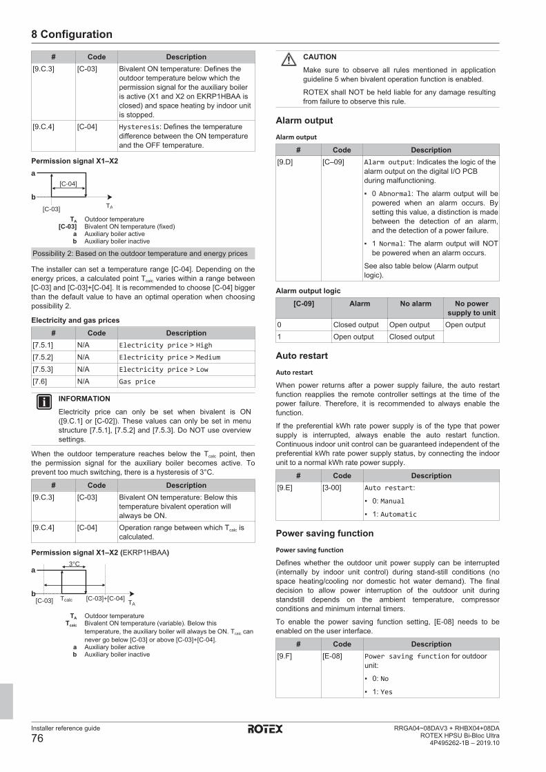
8 Configuration
Installer reference guide
76RRGA04~08DAV3 + RHBX04+08DA
ROTEX HPSU Bi-Bloc Ultra4P495262-1B – 2019.10
# Code Description[9.C.3] [C-03] Bivalent ON temperature: Defines the
outdoor temperature below which thepermission signal for the auxiliary boileris active (X1 and X2 on EKRP1HBAA isclosed) and space heating by indoor unitis stopped.
[9.C.4] [C-04] Hysteresis: Defines the temperaturedifference between the ON temperatureand the OFF temperature.
Permission signal X1–X2
TA[C-03]
[C-04]a
b
TA Outdoor temperature[C-03] Bivalent ON temperature (fixed)
a Auxiliary boiler activeb Auxiliary boiler inactive
Possibility 2: Based on the outdoor temperature and energy prices
The installer can set a temperature range [C‑04]. Depending on theenergy prices, a calculated point Tcalc varies within a range between[C‑03] and [C‑03]+[C‑04]. It is recommended to choose [C‑04] biggerthan the default value to have an optimal operation when choosingpossibility 2.
Electricity and gas prices# Code Description
[7.5.1] N/A Electricity price > High[7.5.2] N/A Electricity price > Medium[7.5.3] N/A Electricity price > Low[7.6] N/A Gas price
INFORMATIONElectricity price can only be set when bivalent is ON([9.C.1] or [C-02]). These values can only be set in menustructure [7.5.1], [7.5.2] and [7.5.3]. Do NOT use overviewsettings.
When the outdoor temperature reaches below the Tcalc point, thenthe permission signal for the auxiliary boiler becomes active. Toprevent too much switching, there is a hysteresis of 3°C.
# Code Description[9.C.3] [C-03] Bivalent ON temperature: Below this
temperature bivalent operation willalways be ON.
[9.C.4] [C-04] Operation range between which Tcalc iscalculated.
Permission signal X1–X2 (EKRP1HBAA)
TATcalc [C-03]+[C-04]
3°C
[C-03]
a
b
TA Outdoor temperatureTcalc Bivalent ON temperature (variable). Below this
temperature, the auxiliary boiler will always be ON. Tcalc cannever go below [C‑03] or above [C‑03]+[C‑04].
a Auxiliary boiler activeb Auxiliary boiler inactive
CAUTIONMake sure to observe all rules mentioned in applicationguideline 5 when bivalent operation function is enabled.
ROTEX shall NOT be held liable for any damage resultingfrom failure to observe this rule.
Alarm outputAlarm output
# Code Description[9.D] [C–09] Alarm output: Indicates the logic of the
alarm output on the digital I/O PCBduring malfunctioning.
▪ 0 Abnormal: The alarm output will bepowered when an alarm occurs. Bysetting this value, a distinction is madebetween the detection of an alarm,and the detection of a power failure.
▪ 1 Normal: The alarm output will NOTbe powered when an alarm occurs.
See also table below (Alarm outputlogic).
Alarm output logic[C-09] Alarm No alarm No power
supply to unit0 Closed output Open output Open output1 Open output Closed output
Auto restartAuto restart
When power returns after a power supply failure, the auto restartfunction reapplies the remote controller settings at the time of thepower failure. Therefore, it is recommended to always enable thefunction.
If the preferential kWh rate power supply is of the type that powersupply is interrupted, always enable the auto restart function.Continuous indoor unit control can be guaranteed independent of thepreferential kWh rate power supply status, by connecting the indoorunit to a normal kWh rate power supply.
# Code Description[9.E] [3-00] Auto restart:
▪ 0: Manual
▪ 1: Automatic
Power saving functionPower saving function
Defines whether the outdoor unit power supply can be interrupted(internally by indoor unit control) during stand-still conditions (nospace heating/cooling nor domestic hot water demand). The finaldecision to allow power interruption of the outdoor unit duringstandstill depends on the ambient temperature, compressorconditions and minimum internal timers.
To enable the power saving function setting, [E‑08] needs to beenabled on the user interface.
# Code Description[9.F] [E‑08] Power saving function for outdoor
unit:
▪ 0: No
▪ 1: Yes

8 Configuration
Installer reference guide
77RRGA04~08DAV3 + RHBX04+08DAROTEX HPSU Bi-Bloc Ultra4P495262-1B – 2019.10
Disable protections
INFORMATIONProtective functions – "Installer-on-site mode". Thesoftware is equipped with protective functions, such asroom antifrost. The unit automatically runs these functionswhen necessary.
During installation or service this behaviour is undesired.Therefore, the protective functions can be disabled:
▪ At first power-on: The protective functions aredisabled by default. After 36 h they will be automaticallyenabled.
▪ Afterwards: An installer can manually disable theprotective functions by setting [9.G]: Disableprotections=Yes. After his work is done, he canenable the protective functions by setting [9.G]:Disable protections=No.
# Code Description[9.G] N/A Disable protections
▪ 0: No
▪ 1: Yes
Forced defrostForced defrostManually start a defrost operation.
# Code Description[9.H] N/A Do you want to start a defrost operation?
▪ Back
▪ OK
NOTICEForced defrost start-up. You can only start forced defrostwhen the heating operation has been running for a while.
Overview field settingsAll settings can be done using the menu structure. If for any reason itis required to change a setting using the overview settings, then theoverview settings can be accessed in the field settings overview [9.I].See "To modify an overview setting" [4 48].
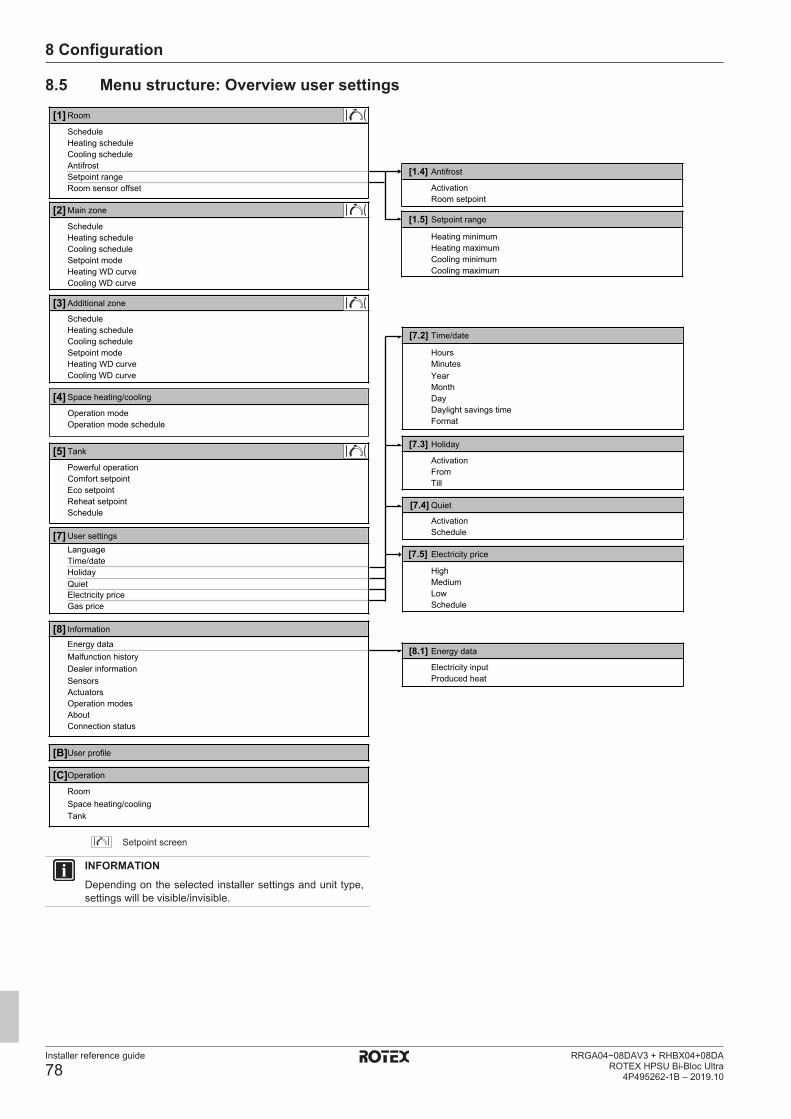
8 Configuration
Installer reference guide
78RRGA04~08DAV3 + RHBX04+08DA
ROTEX HPSU Bi-Bloc Ultra4P495262-1B – 2019.10
8.5 Menu structure: Overview user settings
[1] Room
Room sensor offsetSetpoint rangeAntifrostCooling scheduleHeating scheduleSchedule
[2] Main zone
ScheduleHeating schedule
Setpoint modeCooling schedule
Heating WD curveCooling WD curve
[3] Additional zone
ScheduleHeating schedule
Setpoint modeCooling schedule
Heating WD curveCooling WD curve
[4] Space heating/cooling
Operation modeOperation mode schedule
[5] Tank
Powerful operationComfort setpointEco setpointReheat setpointSchedule
[7] User settingsLanguageTime/dateHolidayQuietElectricity priceGas price
[8] Information
Energy dataMalfunction historyDealer informationSensorsActuatorsOperation modesAboutConnection status
[B]User profile
[C]Operation
RoomSpace heating/coolingTank
[1.4] Antifrost
ActivationRoom setpoint
[1.5] Setpoint range
Heating minimumHeating maximumCooling minimumCooling maximum
[7.2] Time/date
HoursMinutesYearMonthDayDaylight savings timeFormat
[7.3] Holiday
ActivationFromTill
[7.4] Quiet
ActivationSchedule
[7.5] Electricity price
HighMediumLowSchedule
[8.1] Energy data
Electricity inputProduced heat
Setpoint screen
INFORMATIONDepending on the selected installer settings and unit type,settings will be visible/invisible.
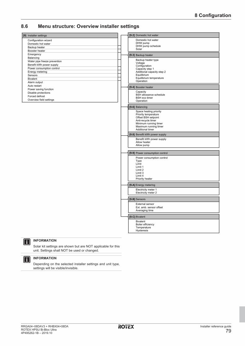
8 Configuration
Installer reference guide
79RRGA04~08DAV3 + RHBX04+08DAROTEX HPSU Bi-Bloc Ultra4P495262-1B – 2019.10
8.6 Menu structure: Overview installer settings[9] Installer settings
Configuration wizardDomestic hot waterBackup heaterBooster heaterEmergencyBalancingWater pipe freeze preventionBenefit kWh power supplyPower consumption controlEnergy meteringSensorsBivalentAlarm outputAuto restartPower saving functionDisable protections
Overview field settingsForced defrost
[9.2] Domestic hot water
Domestic hot waterDHW pumpDHW pump scheduleSolar
[9.3] Backup heater
Backup heater typeVoltageConfiguration
Additional capacity step 2Capacity step 1
EquilibriumEquilibrium temperatureOperation
[9.4] Booster heater
CapacityBSH allowance scheduleBSH eco timerOperation
[9.6] BalancingSpace heating priorityPriority temperatureOffset BSH setpoint
Minimum running timerAnti-recycle timer
Maximum running timerAdditional timer
[9.8] Benefit kWh power supply
Benefit kWh power supplyAllow heaterAllow pump
[9.9] Power consumption control
Power consumption controlTypeLimitLimit 1Limit 2Limit 3Limit 4Priority heater
[9.A] Energy metering
Electricity meter 2Electricity meter 1
[9.B] Sensors
External sensorExt. amb. sensor offsetAveraging time
[9.C] Bivalent
BivalentBoiler efficiencyTemperatureHysteresis
INFORMATIONSolar kit settings are shown but are NOT applicable for thisunit. Settings shall NOT be used or changed.
INFORMATIONDepending on the selected installer settings and unit type,settings will be visible/invisible.
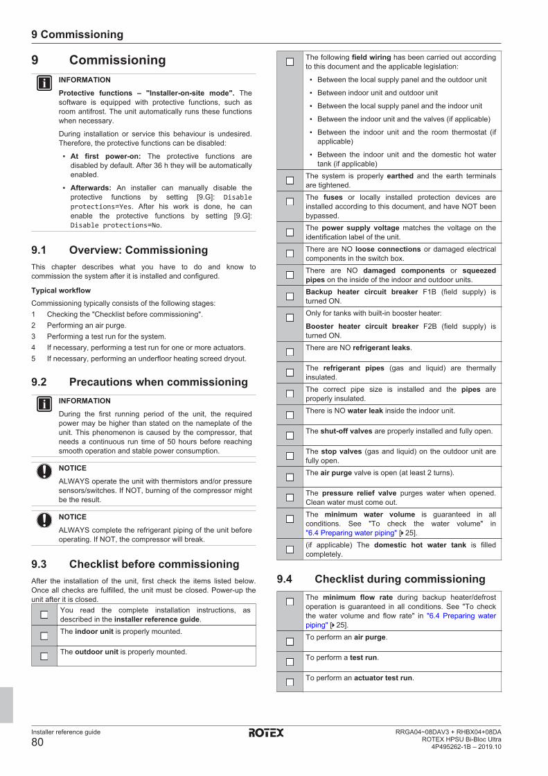
9 Commissioning
Installer reference guide
80RRGA04~08DAV3 + RHBX04+08DA
ROTEX HPSU Bi-Bloc Ultra4P495262-1B – 2019.10
9 CommissioningINFORMATIONProtective functions – "Installer-on-site mode". Thesoftware is equipped with protective functions, such asroom antifrost. The unit automatically runs these functionswhen necessary.
During installation or service this behaviour is undesired.Therefore, the protective functions can be disabled:
▪ At first power-on: The protective functions aredisabled by default. After 36 h they will be automaticallyenabled.
▪ Afterwards: An installer can manually disable theprotective functions by setting [9.G]: Disableprotections=Yes. After his work is done, he canenable the protective functions by setting [9.G]:Disable protections=No.
9.1 Overview: CommissioningThis chapter describes what you have to do and know tocommission the system after it is installed and configured.
Typical workflowCommissioning typically consists of the following stages:1 Checking the "Checklist before commissioning".2 Performing an air purge.3 Performing a test run for the system.4 If necessary, performing a test run for one or more actuators.5 If necessary, performing an underfloor heating screed dryout.
9.2 Precautions when commissioningINFORMATIONDuring the first running period of the unit, the requiredpower may be higher than stated on the nameplate of theunit. This phenomenon is caused by the compressor, thatneeds a continuous run time of 50 hours before reachingsmooth operation and stable power consumption.
NOTICEALWAYS operate the unit with thermistors and/or pressuresensors/switches. If NOT, burning of the compressor mightbe the result.
NOTICEALWAYS complete the refrigerant piping of the unit beforeoperating. If NOT, the compressor will break.
9.3 Checklist before commissioningAfter the installation of the unit, first check the items listed below.Once all checks are fulfilled, the unit must be closed. Power-up theunit after it is closed.
You read the complete installation instructions, asdescribed in the installer reference guide.The indoor unit is properly mounted.
The outdoor unit is properly mounted.
The following field wiring has been carried out accordingto this document and the applicable legislation:
▪ Between the local supply panel and the outdoor unit
▪ Between indoor unit and outdoor unit
▪ Between the local supply panel and the indoor unit
▪ Between the indoor unit and the valves (if applicable)
▪ Between the indoor unit and the room thermostat (ifapplicable)
▪ Between the indoor unit and the domestic hot watertank (if applicable)
The system is properly earthed and the earth terminalsare tightened.The fuses or locally installed protection devices areinstalled according to this document, and have NOT beenbypassed.The power supply voltage matches the voltage on theidentification label of the unit.There are NO loose connections or damaged electricalcomponents in the switch box.There are NO damaged components or squeezedpipes on the inside of the indoor and outdoor units.Backup heater circuit breaker F1B (field supply) isturned ON.Only for tanks with built-in booster heater:
Booster heater circuit breaker F2B (field supply) isturned ON.There are NO refrigerant leaks.
The refrigerant pipes (gas and liquid) are thermallyinsulated.The correct pipe size is installed and the pipes areproperly insulated.There is NO water leak inside the indoor unit.
The shut-off valves are properly installed and fully open.
The stop valves (gas and liquid) on the outdoor unit arefully open.The air purge valve is open (at least 2 turns).
The pressure relief valve purges water when opened.Clean water must come out.The minimum water volume is guaranteed in allconditions. See "To check the water volume" in"6.4 Preparing water piping" [4 25].(if applicable) The domestic hot water tank is filledcompletely.
9.4 Checklist during commissioningThe minimum flow rate during backup heater/defrostoperation is guaranteed in all conditions. See "To checkthe water volume and flow rate" in "6.4 Preparing waterpiping" [4 25].To perform an air purge.
To perform a test run.
To perform an actuator test run.
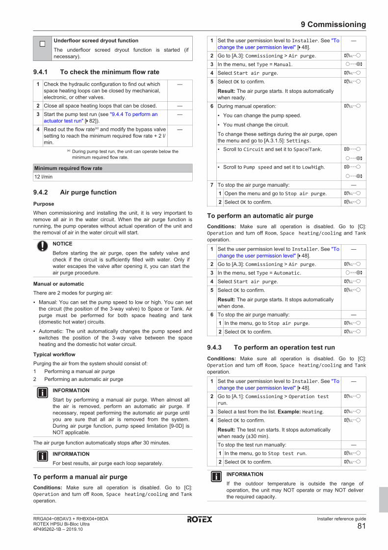
9 Commissioning
Installer reference guide
81RRGA04~08DAV3 + RHBX04+08DAROTEX HPSU Bi-Bloc Ultra4P495262-1B – 2019.10
Underfloor screed dryout functionThe underfloor screed dryout function is started (ifnecessary).
9.4.1 To check the minimum flow rate
1 Check the hydraulic configuration to find out whichspace heating loops can be closed by mechanical,electronic, or other valves.
—
2 Close all space heating loops that can be closed. —3 Start the pump test run (see "9.4.4 To perform an
actuator test run" [4 82]).—
4 Read out the flow rate(a) and modify the bypass valvesetting to reach the minimum required flow rate + 2 l/min.
—
(a) During pump test run, the unit can operate below theminimum required flow rate.
Minimum required flow rate12 l/min
9.4.2 Air purge functionPurposeWhen commissioning and installing the unit, it is very important toremove all air in the water circuit. When the air purge function isrunning, the pump operates without actual operation of the unit andthe removal of air in the water circuit will start.
NOTICEBefore starting the air purge, open the safety valve andcheck if the circuit is sufficiently filled with water. Only ifwater escapes the valve after opening it, you can start theair purge procedure.
Manual or automaticThere are 2 modes for purging air:
▪ Manual: You can set the pump speed to low or high. You can setthe circuit (the position of the 3-way valve) to Space or Tank. Airpurge must be performed for both space heating and tank(domestic hot water) circuits.
▪ Automatic: The unit automatically changes the pump speed andswitches the position of the 3-way valve between the spaceheating and the domestic hot water circuit.
Typical workflowPurging the air from the system should consist of:1 Performing a manual air purge2 Performing an automatic air purge
INFORMATIONStart by performing a manual air purge. When almost allthe air is removed, perform an automatic air purge. Ifnecessary, repeat performing the automatic air purge untilyou are sure that all air is removed from the system.During air purge function, pump speed limitation [9‑0D] isNOT applicable.
The air purge function automatically stops after 30 minutes.
INFORMATIONFor best results, air purge each loop separately.
To perform a manual air purgeConditions: Make sure all operation is disabled. Go to [C]:Operation and turn off Room, Space heating/cooling and Tankoperation.
1 Set the user permission level to Installer. See "Tochange the user permission level" [4 48].
—
2 Go to [A.3]: Commissioning > Air purge.3 In the menu, set Type = Manual.4 Select Start air purge.5 Select OK to confirm.
Result: The air purge starts. It stops automaticallywhen ready.
6 During manual operation:
▪ You can change the pump speed.
▪ You must change the circuit.
To change these settings during the air purge, openthe menu and go to [A.3.1.5]: Settings.▪ Scroll to Circuit and set it to Space/Tank.
▪ Scroll to Pump speed and set it to Low/High.
7 To stop the air purge manually: —1 Open the menu and go to Stop air purge.2 Select OK to confirm.
To perform an automatic air purgeConditions: Make sure all operation is disabled. Go to [C]:Operation and turn off Room, Space heating/cooling and Tankoperation.
1 Set the user permission level to Installer. See "Tochange the user permission level" [4 48].
—
2 Go to [A.3]: Commissioning > Air purge.3 In the menu, set Type = Automatic.4 Select Start air purge.5 Select OK to confirm.
Result: The air purge starts. It stops automaticallywhen done.
6 To stop the air purge manually: —1 In the menu, go to Stop air purge.2 Select OK to confirm.
9.4.3 To perform an operation test runConditions: Make sure all operation is disabled. Go to [C]:Operation and turn off Room, Space heating/cooling and Tankoperation.
1 Set the user permission level to Installer. See "Tochange the user permission level" [4 48].
—
2 Go to [A.1]: Commissioning > Operation testrun.
3 Select a test from the list. Example: Heating.4 Select OK to confirm.
Result: The test run starts. It stops automaticallywhen ready (±30 min).To stop the test run manually: —1 In the menu, go to Stop test run.2 Select OK to confirm.
INFORMATIONIf the outdoor temperature is outside the range ofoperation, the unit may NOT operate or may NOT deliverthe required capacity.
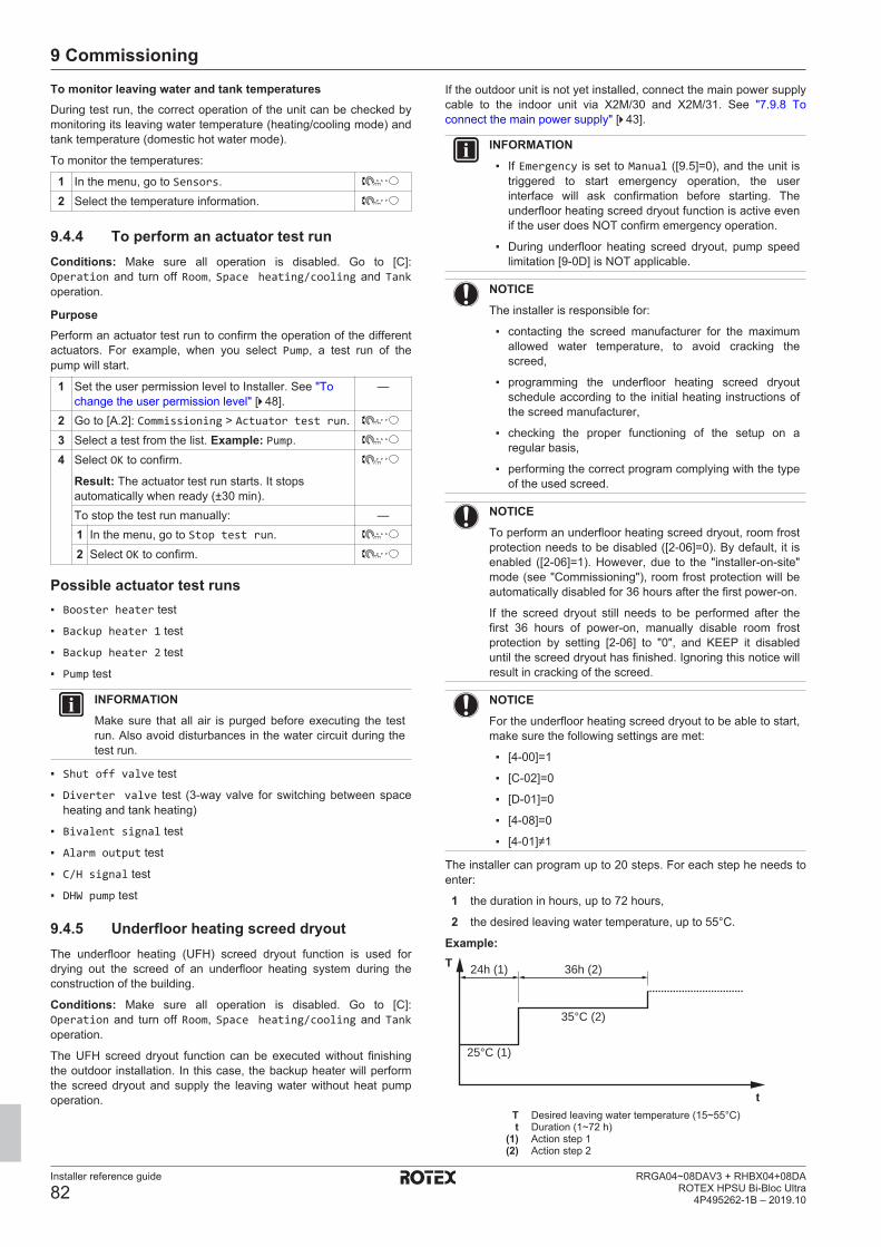
9 Commissioning
Installer reference guide
82RRGA04~08DAV3 + RHBX04+08DA
ROTEX HPSU Bi-Bloc Ultra4P495262-1B – 2019.10
To monitor leaving water and tank temperaturesDuring test run, the correct operation of the unit can be checked bymonitoring its leaving water temperature (heating/cooling mode) andtank temperature (domestic hot water mode).
To monitor the temperatures:
1 In the menu, go to Sensors.2 Select the temperature information.
9.4.4 To perform an actuator test runConditions: Make sure all operation is disabled. Go to [C]:Operation and turn off Room, Space heating/cooling and Tankoperation.
PurposePerform an actuator test run to confirm the operation of the differentactuators. For example, when you select Pump, a test run of thepump will start.
1 Set the user permission level to Installer. See "Tochange the user permission level" [4 48].
—
2 Go to [A.2]: Commissioning > Actuator test run.3 Select a test from the list. Example: Pump.4 Select OK to confirm.
Result: The actuator test run starts. It stopsautomatically when ready (±30 min).To stop the test run manually: —1 In the menu, go to Stop test run.2 Select OK to confirm.
Possible actuator test runs▪ Booster heater test
▪ Backup heater 1 test
▪ Backup heater 2 test
▪ Pump test
INFORMATIONMake sure that all air is purged before executing the testrun. Also avoid disturbances in the water circuit during thetest run.
▪ Shut off valve test
▪ Diverter valve test (3-way valve for switching between spaceheating and tank heating)
▪ Bivalent signal test
▪ Alarm output test
▪ C/H signal test
▪ DHW pump test
9.4.5 Underfloor heating screed dryoutThe underfloor heating (UFH) screed dryout function is used fordrying out the screed of an underfloor heating system during theconstruction of the building.
Conditions: Make sure all operation is disabled. Go to [C]:Operation and turn off Room, Space heating/cooling and Tankoperation.
The UFH screed dryout function can be executed without finishingthe outdoor installation. In this case, the backup heater will performthe screed dryout and supply the leaving water without heat pumpoperation.
If the outdoor unit is not yet installed, connect the main power supplycable to the indoor unit via X2M/30 and X2M/31. See "7.9.8 Toconnect the main power supply" [4 43].
INFORMATION▪ If Emergency is set to Manual ([9.5]=0), and the unit is
triggered to start emergency operation, the userinterface will ask confirmation before starting. Theunderfloor heating screed dryout function is active evenif the user does NOT confirm emergency operation.
▪ During underfloor heating screed dryout, pump speedlimitation [9‑0D] is NOT applicable.
NOTICEThe installer is responsible for:
▪ contacting the screed manufacturer for the maximumallowed water temperature, to avoid cracking thescreed,
▪ programming the underfloor heating screed dryoutschedule according to the initial heating instructions ofthe screed manufacturer,
▪ checking the proper functioning of the setup on aregular basis,
▪ performing the correct program complying with the typeof the used screed.
NOTICETo perform an underfloor heating screed dryout, room frostprotection needs to be disabled ([2‑06]=0). By default, it isenabled ([2‑06]=1). However, due to the "installer-on-site"mode (see "Commissioning"), room frost protection will beautomatically disabled for 36 hours after the first power-on.
If the screed dryout still needs to be performed after thefirst 36 hours of power-on, manually disable room frostprotection by setting [2‑06] to "0", and KEEP it disableduntil the screed dryout has finished. Ignoring this notice willresult in cracking of the screed.
NOTICEFor the underfloor heating screed dryout to be able to start,make sure the following settings are met:
▪ [4‑00]=1
▪ [C‑02]=0
▪ [D‑01]=0
▪ [4‑08]=0
▪ [4‑01]≠1
The installer can program up to 20 steps. For each step he needs toenter:
1 the duration in hours, up to 72 hours,
2 the desired leaving water temperature, up to 55°C.
Example:
t
T
A125°C (1)
35°C (2)
24h (1) 36h (2)
T Desired leaving water temperature (15~55°C)t Duration (1~72 h)
(1) Action step 1(2) Action step 2
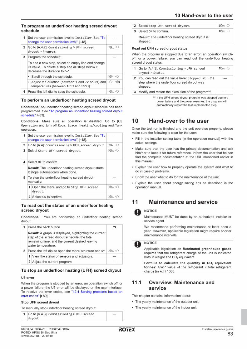
10 Hand-over to the user
Installer reference guide
83RRGA04~08DAV3 + RHBX04+08DAROTEX HPSU Bi-Bloc Ultra4P495262-1B – 2019.10
To program an underfloor heating screed dryoutschedule
1 Set the user permission level to Installer. See "Tochange the user permission level" [4 48].
—
2 Go to [A.4.2]: Commissioning > UFH screeddryout > Program.
3 Program the schedule:
To add a new step, select an empty line and changeits value. To delete a step and all steps below it,decrease the duration to "–".
—
▪ Scroll through the schedule.▪ Adjust the duration (between 1 and 72 hours) and
temperatures (between 15°C and 55°C).4 Press the left dial to save the schedule.
To perform an underfloor heating screed dryoutConditions: An underfloor heating screed dryout schedule has beenprogrammed. See "To program an underfloor heating screed dryoutschedule" [4 83].
Conditions: Make sure all operation is disabled. Go to [C]:Operation and turn off Room, Space heating/cooling and Tankoperation.
1 Set the user permission level to Installer. See "Tochange the user permission level" [4 48].
—
2 Go to [A.4]: Commissioning > UFH screed dryout.3 Select Start UFH screed dryout.
4 Select OK to confirm.
Result: The underfloor heating screed dryout starts.It stops automatically when done.
5 To stop the underfloor heating screed dryoutmanually:
—
1 Open the menu and go to Stop UFH screeddryout.
2 Select OK to confirm.
To read out the status of an underfloor heatingscreed dryoutConditions: You are performing an underfloor heating screeddryout.
1 Press the back button.
Result: A graph is displayed, highlighting the currentstep of the screed dryout schedule, the totalremaining time, and the current desired leavingwater temperature.
2 Press the left dial to open the menu structure and to:1 View the status of sensors and actuators. —2 Adjust the current program —
To stop an underfloor heating (UFH) screed dryoutU3-errorWhen the program is stopped by an error, an operation switch off, ora power failure, the U3 error will be displayed on the user interface.To resolve the error codes, see "12.4 Solving problems based onerror codes" [4 89].
Stop UFH screed dryoutTo manually stop underfloor heating screed dryout:
1 Go to [A.4.3]: Commissioning > UFH screeddryout
—
2 Select Stop UFH screed dryout.3 Select OK to confirm.
Result: The underfloor heating screed dryout isstopped.
Read out UFH screed dryout statusWhen the program is stopped due to an error, an operation switch-off, or a power failure, you can read out the underfloor heatingscreed dryout status:
1 Go to [A.4.3]: Commissioning > UFH screeddryout > Status
2 You can read out the value here: Stopped at + thestep where the underfloor screed dryout wasstopped.
—
3 Modify and restart the execution of the program(a). —(a) If the UFH screed dryout program was stopped due to a
power failure and the power resumes, the program willautomatically restart the last implemented step.
10 Hand-over to the userOnce the test run is finished and the unit operates properly, pleasemake sure the following is clear for the user:
▪ Fill in the installer setting table (in the operation manual) with theactual settings.
▪ Make sure that the user has the printed documentation and askhim/her to keep it for future reference. Inform the user that he canfind the complete documentation at the URL mentioned earlier inthis manual.
▪ Explain the user how to properly operate the system and what todo in case of problems.
▪ Show the user what to do for the maintenance of the unit.
▪ Explain the user about energy saving tips as described in theoperation manual.
11 Maintenance and serviceNOTICEMaintenance MUST be done by an authorized installer orservice agent.
We recommend performing maintenance at least once ayear. However, applicable legislation might require shortermaintenance intervals.
NOTICEApplicable legislation on fluorinated greenhouse gasesrequires that the refrigerant charge of the unit is indicatedboth in weight and CO2 equivalent.
Formula to calculate the quantity in CO2 equivalenttonnes: GWP value of the refrigerant × total refrigerantcharge [in kg] / 1000
11.1 Overview: Maintenance andservice
This chapter contains information about:
▪ The yearly maintenance of the outdoor unit
▪ The yearly maintenance of the indoor unit

11 Maintenance and service
Installer reference guide
84RRGA04~08DAV3 + RHBX04+08DA
ROTEX HPSU Bi-Bloc Ultra4P495262-1B – 2019.10
11.2 Maintenance safety precautionsDANGER: RISK OF ELECTROCUTION
DANGER: RISK OF BURNING
NOTICE: Risk of electrostatic dischargeBefore performing any maintenance or service work, toucha metal part of the unit in order to eliminate static electricityand to protect the PCB.
11.3 Checklist for yearly maintenanceof the outdoor unit
Check the following at least once a year:
▪ Heat exchangerThe heat exchanger of the outdoor unit can get blocked up due todust, dirt, leaves, etc. It is recommended to clean the heatexchanger yearly. A blocked heat exchanger can lead to too lowpressure or too high pressure leading to worse performance.
11.4 Checklist for yearly maintenanceof the indoor unit
Check the following at least once a year:
▪ Water pressure
▪ Magnetic filter/dirt separator
▪ Water pressure relief valve
▪ Pressure relief valve of the domestic hot water tank
▪ Switch box
▪ Booster heater of the domestic hot water tank
Water pressureKeep water pressure above 1 bar. If it is lower, add water.
Magnetic filter/dirt separator
b
a
c
da Screw connectionb Magnetic sleevec Drain valved Drain cap
The yearly maintenance of the magnetic filter/dirt separator consistsof:
▪ Checking if both parts of the magnetic filter/dirt separator are stillscrewed tight (a).
▪ Emptying the dirt separator as follows:
1 Take off the magnetic sleeve (b).
2 Unscrew the drain cap (d).
3 Connect a drain hose to the bottom of the water filter so that thewater and dirt can be collected in a suitable container (bottle,sink...).
4 Open the drain valve for a couple of seconds (c).
Result: Water and dirt will come out.
5 Close the drain valve.
6 Screw the drain cap back on.
7 Reattach the magnetic sleeve.
8 Check the pressure of the water circuit. If required, add water.
NOTICE▪ When checking the magnetic filter/dirt separator for
tightness, hold it firmly, so as NOT to apply stress tothe water piping.
▪ Do NOT isolate the magnetic filter/dirt separator byclosing the shut‑off valves. To properly empty the dirtseparator, sufficient pressure is required.
▪ To prevent dirt from remaining in the dirt separator,ALWAYS take off the magnetic sleeve.
▪ ALWAYS first unscrew the drain cap, and connect adrain hose to the bottom of the water filter, then openthe drain valve.
INFORMATIONFor yearly maintenance, you do not have to remove thewater filter from the unit to clean it. But in case of troublewith the water filter, you might have to remove it so thatyou can thoroughly clean it. Then you need to do asfollows:
▪ "11.5.1 To remove the water filter" [4 85]
▪ "11.5.2 To clean the water filter in case oftrouble" [4 85]
▪ "11.5.3 To install the water filter" [4 86]
Water pressure relief valveOpen the valve and check if it operates correctly. The water may bevery hot!Checkpoints are:
▪ The water flow coming from the relief valve is high enough, noblockage of the valve or in between piping is suspected.
▪ Dirty water coming out of the relief valve:
▪ open the valve until the discharged water does NOT contain dirtanymore
▪ flush the system
To make sure this water originates from the tank, check after a tankheat up cycle.
It is recommended to do this maintenance more frequently.
Pressure relief valve of the domestic hot water tank (fieldsupply)Open the valve.
CAUTIONWater coming out of the valve may be very hot.
▪ Check if nothing blocks the water in the valve or in betweenpiping. The water flow coming from the relief valve must be highenough.
▪ Check if the water coming out of the relief valve is clean. If itcontains debris or dirt:
▪ Open the valve until the discharged water does not containdebris or dirt anymore.
▪ Flush and clean the complete tank, including the pipingbetween the relief valve and cold water inlet.
To make sure this water originates from the tank, check after a tankheat up cycle.

11 Maintenance and service
Installer reference guide
85RRGA04~08DAV3 + RHBX04+08DAROTEX HPSU Bi-Bloc Ultra4P495262-1B – 2019.10
INFORMATIONIt is recommended to perform this maintenance more thanonce a year.
Switch box▪ Carry out a thorough visual inspection of the switch box and look
for obvious defects such as loose connections or defective wiring.
▪ Using an ohmmeter, check if contactors K1M, K2M, K3M and K5M(depending on your installation) operate correctly. All contacts ofthese contactors must be in open position when the power isturned OFF.
WARNINGIf the internal wiring is damaged, it has to be replaced bythe manufacturer, its service agent or similarly qualifiedpersons.
Booster heater of the domestic hot water tank
INFORMATIONOnly for wall-mounted units equipped with a domestic hotwater tank with a built-in electrical booster heater (RKHW).
It is recommended to remove lime buildup on the booster heater toextend its life span, especially in regions with hard water. To do so,drain the domestic hot water tank, remove the booster heater fromthe domestic hot water tank and immerse in a bucket (or similar) withlime-removing product for 24 hours.
11.5 About cleaning the water filter incase of trouble
INFORMATIONFor yearly maintenance, you do not have to remove thewater filter from the unit to clean it. But in case of troublewith the water filter, you might have to remove it so thatyou can thoroughly clean it. Then you need to do asfollows:
▪ "11.5.1 To remove the water filter" [4 85]
▪ "11.5.2 To clean the water filter in case oftrouble" [4 85]
▪ "11.5.3 To install the water filter" [4 86]
11.5.1 To remove the water filterPrerequisite: Stop the unit operation via the user interface.Prerequisite: Turn OFF the respective circuit breaker.
1 The water filter is located behind the switch box. To get accessto it, see:
"7.2.3 To open the indoor unit" [4 30]
2 Close the stop valves of the water circuit.
3 Close the valve (if equipped) of the water circuit towards theexpansion vessel.
4 Remove the cap on the bottom of the magnetic filter/dirtseparator.
5 Connect a drain hose to the bottom of the water filter.
6 Open the valve on the bottom of the water filter to drain waterfrom the water circuit. Collect the drained water in a bottle, sink,… using the installed drain hose.
7 Remove the 2 clips that fix the water filter.
a
ba
a Clipb Magnetic filter/dirt separator
8 Remove the water filter.
9 Remove the drain hose from the water filter.
CAUTIONAlthough the water circuit is drained, some water may bespilled when removing the magnetic filter/dirt separatorfrom the filter housing. ALWAYS clean up spilled water.
11.5.2 To clean the water filter in case of trouble1 Remove the water filter from the unit. See "11.5.1 To remove
the water filter" [4 85].
CAUTIONTo protect the piping connected to the magnetic filter/dirtseparator from damage it is recommended to perform thisprocedure with the magnetic filter/dirt separator removedfrom the unit.
2 Unscrew the bottom of the water filter housing. Use anappropriate tool if needed.
CAUTIONOpening the magnetic filter/dirt separator is ONLY requiredin case of severe issues. Preferably this action is never tobe done during the complete lifetime of the magnetic filter/dirt separator.
a
b
a Bottom part to be unscrewedb Water filter housing
3 Remove the strainer and the rolled‑up filter from the water filterhousing and clean with water.
4 Install the cleaned rolled‑up filter and strainer in the water filterhousing.
INFORMATIONCorrectly install the strainer in the magnetic filter/dirtseparator housing using the protrusions.
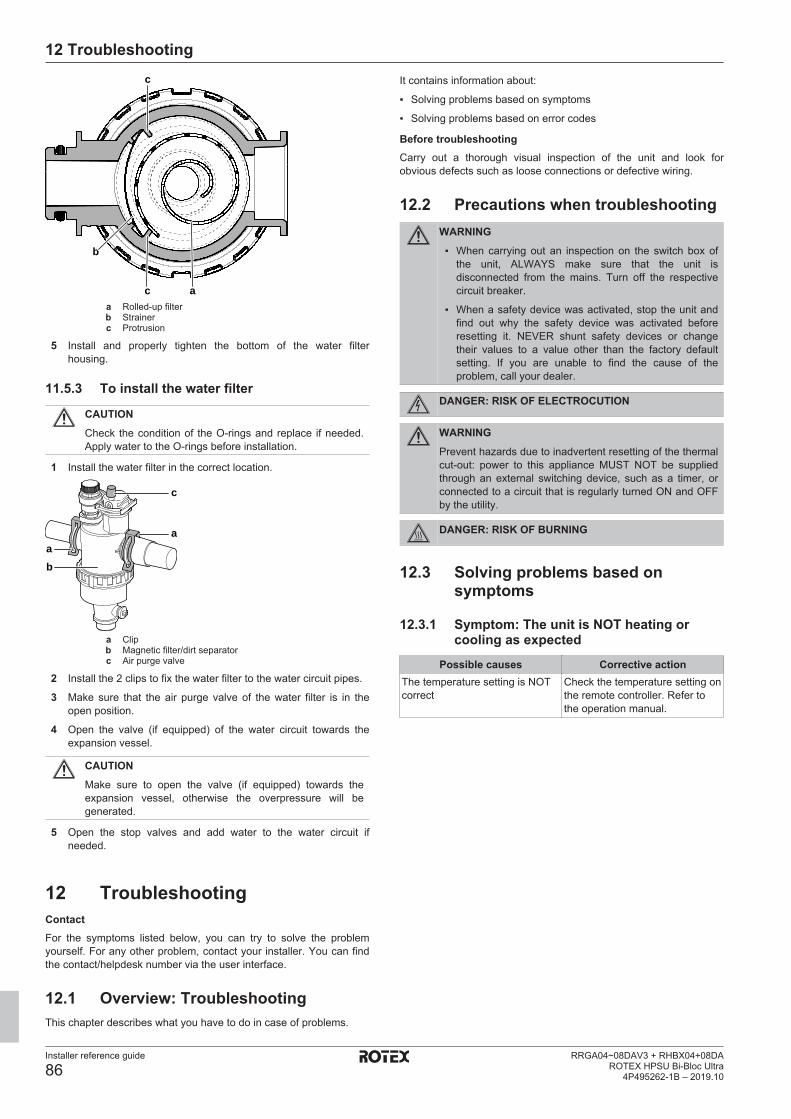
12 Troubleshooting
Installer reference guide
86RRGA04~08DAV3 + RHBX04+08DA
ROTEX HPSU Bi-Bloc Ultra4P495262-1B – 2019.10
a
b
c
c
a Rolled‑up filterb Strainerc Protrusion
5 Install and properly tighten the bottom of the water filterhousing.
11.5.3 To install the water filter
CAUTIONCheck the condition of the O-rings and replace if needed.Apply water to the O-rings before installation.
1 Install the water filter in the correct location.
a
c
ba
a Clipb Magnetic filter/dirt separatorc Air purge valve
2 Install the 2 clips to fix the water filter to the water circuit pipes.
3 Make sure that the air purge valve of the water filter is in theopen position.
4 Open the valve (if equipped) of the water circuit towards theexpansion vessel.
CAUTIONMake sure to open the valve (if equipped) towards theexpansion vessel, otherwise the overpressure will begenerated.
5 Open the stop valves and add water to the water circuit ifneeded.
12 TroubleshootingContactFor the symptoms listed below, you can try to solve the problemyourself. For any other problem, contact your installer. You can findthe contact/helpdesk number via the user interface.
12.1 Overview: TroubleshootingThis chapter describes what you have to do in case of problems.
It contains information about:
▪ Solving problems based on symptoms
▪ Solving problems based on error codes
Before troubleshootingCarry out a thorough visual inspection of the unit and look forobvious defects such as loose connections or defective wiring.
12.2 Precautions when troubleshootingWARNING▪ When carrying out an inspection on the switch box of
the unit, ALWAYS make sure that the unit isdisconnected from the mains. Turn off the respectivecircuit breaker.
▪ When a safety device was activated, stop the unit andfind out why the safety device was activated beforeresetting it. NEVER shunt safety devices or changetheir values to a value other than the factory defaultsetting. If you are unable to find the cause of theproblem, call your dealer.
DANGER: RISK OF ELECTROCUTION
WARNINGPrevent hazards due to inadvertent resetting of the thermalcut-out: power to this appliance MUST NOT be suppliedthrough an external switching device, such as a timer, orconnected to a circuit that is regularly turned ON and OFFby the utility.
DANGER: RISK OF BURNING
12.3 Solving problems based onsymptoms
12.3.1 Symptom: The unit is NOT heating orcooling as expected
Possible causes Corrective actionThe temperature setting is NOTcorrect
Check the temperature setting onthe remote controller. Refer tothe operation manual.
12 Troubleshooting
Installer reference guide
87RRGA04~08DAV3 + RHBX04+08DAROTEX HPSU Bi-Bloc Ultra4P495262-1B – 2019.10
Possible causes Corrective actionThe water flow is too low Check and make sure that:
▪ All shut-off valves of the watercircuit are completely open.
▪ The water filter is clean. Cleanif necessary.
▪ There is no air in the system.Purge air if necessary. Youcan purge air manually (see"To perform a manual airpurge" [4 81]) or use theautomatic air purge function(see "To perform an automaticair purge" [4 81]).
▪ The water pressure is >1 bar.
▪ The expansion vessel is NOTbroken.
▪ The valve (if equipped) of thewater circuit towards theexpansion vessel is open.
▪ The resistance in the watercircuit is NOT too high for thepump (see the ESP curve inthe "Technical data" chapter).
If the problem persists after youhave conducted all of the abovechecks, contact your dealer. Insome cases, it is normal that theunit decides to use a low waterflow.
The water volume in theinstallation is too low
Make sure that the water volumein the installation is above theminimum required value (see"6.4.3 To check the water volumeand flow rate" [4 26]).
12.3.2 Symptom: The compressor does NOTstart (space heating or domestic waterheating)
Possible causes Corrective actionThe unit must start up out of itsoperation range (the watertemperature is too low)
If the water temperature is toolow, the unit uses the backupheater to reach the minimumwater temperature first (15°C).
Check and make sure that:
▪ The power supply to thebackup heater is correctlywired.
▪ The backup heater thermalprotector is NOT activated.
▪ The backup heater contactorsare NOT broken.
If the problem persists after youhave conducted all of the abovechecks, contact your dealer.
The preferential kWh rate powersupply settings and electricalconnections do NOT match
This should match with theconnections as explained in"6.5 Preparing electricalwiring" [4 28] and "7.9.8 Toconnect the main powersupply" [4 43].
Possible causes Corrective actionThe preferential kWh rate signalwas sent by the electricitycompany
Wait for the power to return (2hours max.).
12.3.3 Symptom: The system is making gurglingnoises after commissioning
Possible cause Corrective actionThere is air in the system. Purge air from the system.(a)
Various malfunctions. Check if or is displayedon the home screen of the userinterface. See "12.4.1 To displaythe help text in case of amalfunction" [4 89] for moreinformation about themalfunction.
(a) We recommend to purge air with the air purge functionof the unit (to be performed by the installer). If you purgeair from the heat emitters or collectors, mind thefollowing:
WARNINGAir purging heat emitters or collectors. Before youpurge air from heat emitters or collectors, check if or
is displayed on the home screen of the user interface.
▪ If not, you can purge air immediately.
▪ If yes, make sure that the room where you want topurge air is sufficiently ventilated. Reason: Refrigerantmight leak into the water circuit, and subsequently intothe room when you purge air from the heat emitters orcollectors.
12.3.4 Symptom: The pump is making noise(cavitation)
Possible causes Corrective actionThere is air in the system Purge air manually (see "To
perform a manual airpurge" [4 81]) or use theautomatic air purge function (see"To perform an automatic airpurge" [4 81]).
The water pressure at the pumpinlet is too low
Check and make sure that:
▪ The water pressure is >1 bar.
▪ The water pressure sensor isnot broken.
▪ The expansion vessel is NOTbroken.
▪ The valve (if equipped) of thewater circuit towards theexpansion vessel is open.
▪ The pre-pressure setting of theexpansion vessel is correct(see "6.4.4 Changing the pre-pressure of the expansionvessel" [4 27]).
12.3.5 Symptom: The pressure relief valve opens
Possible causes Corrective actionThe expansion vessel is broken Replace the expansion vessel.
12 Troubleshooting
Installer reference guide
88RRGA04~08DAV3 + RHBX04+08DA
ROTEX HPSU Bi-Bloc Ultra4P495262-1B – 2019.10
Possible causes Corrective actionThe valve (if equipped) of thewater circuit towards theexpansion vessel is closed.
Open the valve.
The water volume in theinstallation is too high
Make sure that the water volumein the installation is below themaximum allowed value (see"6.4.3 To check the water volumeand flow rate" [4 26] and"6.4.4 Changing the pre-pressureof the expansion vessel" [4 27]).
The water circuit head is too high The water circuit head is thedifference in height between theindoor unit and the highest pointof the water circuit. If the indoorunit is located at the highestpoint of the installation, theinstallation height is considered0 m. The maximum water circuithead is 10 m.
Check the installationrequirements.
12.3.6 Symptom: The water pressure relief valveleaks
Possible causes Corrective actionDirt is blocking the waterpressure relief valve outlet
Check whether the pressurerelief valve works correctly byturning the red knob on the valvecounterclockwise:
▪ If you do NOT hear a clackingsound, contact your dealer.
▪ If the water keeps running outof the unit, close both thewater inlet and outlet shut-offvalves first and then contactyour dealer.
12.3.7 Symptom: The space is NOT sufficientlyheated at low outdoor temperatures
Possible causes Corrective actionThe backup heater operation isnot activated
Check the following:
▪ The backup heater operationmode is enabled.Go to: [9.3.8]: Installersettings > Backup heater >Operation [4‑00]
▪ The backup heater overcurrentcircuit breaker is on. If not, turnit back on.
▪ The thermal protector of thebackup heater is NOTactivated. If it has, check thefollowing, and then press thereset button in the switch box:
▪ The water pressure
▪ Whether there is air in thesystem
▪ The air purge operation
Possible causes Corrective actionThe backup heater equilibriumtemperature has not beenconfigured correctly
Increase the equilibriumtemperature to activate thebackup heater operation at ahigher outdoor temperature.
Go to: [9.3.7]: Installersettings > Backup heater >Equilibrium temperature[5‑01]
There is air in the system. Purge air manually orautomatically. See the air purgefunction in the chapter"9 Commissioning" [4 80].
Too much heat pump capacity isused for heating domestic hotwater (applies only toinstallations with a domestic hotwater tank)
Check if the Space heatingpriority settings have beenconfigured appropriately:
▪ Make sure that the Spaceheating priority has beenenabled.Go to [9.6.1]: Installersettings > Balancing >Space heating priority[5‑02]
▪ Increase the "space heatingpriority temperature" toactivate backup heateroperation at a higher outdoortemperature.Go to [9.6.3]: Installersettings > Balancing >Offset BSH setpoint [5‑03]
12.3.8 Symptom: The pressure at the tappingpoint is temporarily unusually high
Possible causes Corrective actionFailing or blocked pressure reliefvalve.
▪ Flush and clean the completetank including the pipingbetween pressure relief valveand the cold water inlet.
▪ Replace the pressure reliefvalve.
12.3.9 Symptom: Decoration panels are pushedaway due to a swollen tank
Possible causes Corrective actionFailing or blocked pressure reliefvalve.
Contact your local dealer.
12.3.10 Symptom: Tank disinfection function isNOT completed correctly (AH-error)
Possible causes Corrective actionThe disinfection function wasinterrupted by domestic hot watertapping
Program the start-up of thedisinfection function when thecoming 4 hours NO domestic hotwater tapping is expected.

12 Troubleshooting
Installer reference guide
89RRGA04~08DAV3 + RHBX04+08DAROTEX HPSU Bi-Bloc Ultra4P495262-1B – 2019.10
Possible causes Corrective actionLarge domestic hot water tappinghappened recently before theprogrammed start-up of thedisinfection function
If in [5.6] Tank > Heat up modethe mode Reheat only orSchedule + reheat is selected,it is recommended to programthe start-up of the disinfectionfunction at least 4 hours laterthan the last expected large hotwater tapping. This start-up canbe set by installer settings(disinfection function).
If in [5.6] Tank > Heat up modethe mode Schedule only isselected, it is recommended toprogram a Eco action 3 hoursbefore the scheduled start-up ofthe disinfection function topreheat the tank.
The disinfection operation wasstopped manually: [C.3]Operation > Tank was turned offduring disinfection.
Do NOT stop tank operationduring disinfection.
12.4 Solving problems based on errorcodes
If the unit runs into a problem, the user interface displays an errorcode. It is important to understand the problem and to takemeasures before resetting an error code. This should be done by alicensed installer or by your local dealer.
This chapter gives you an overview of all possible error codes andtheir descriptions as they appear on the user interface.
For detailed troubleshooting of each error, see the service manual.
12.4.1 To display the help text in case of amalfunction
In case of a malfunction, the following will appear on the homescreen depending on the severity:
▪ : Error
▪ : Malfunction
You can get a short and a long description of the malfunction asfollows:
1 Press the left dial to open the main menu and go toMalfunctioning.
Result: A short description of the error and the errorcode is displayed on the screen.
2 Press in the error screen.
Result: A long description of the error is displayedon the screen.
12.4.2 Error codes: Overview
Error codes of the outdoor unitError code Detailed error
codeDescription
A1 00 Zero cross detectionproblem
A5 00 OU: High pressure peakcut / freeze protectionproblem
E1 00 OU: PCB defect
Error code Detailed errorcode
Description
E3 00 OU: Actuation of highpressure switch (HPS)
E5 00 OU: Overheat of invertercompressor motor
E6 00 OU: Compressor startupdefect
E7 00 OU: Malfunction of outdoorunit fan motor
E8 00 OU: Power input overvoltage
EA 00 OU: Cool/heat switchoverproblem
H0 00 OU: Voltage/current sensorproblem
H3 00 OU: Malfunction of highpressure switch (HPS)
H6 00 OU: Malfunction of positiondetection sensor
H8 00 OU: Malfunction ofcompressor input (CT)system
H9 00 OU: Malfunction of outdoorair thermistor
F3 00 OU: Malfunction ofdischarge pipe temperature
F6 00 OU: Abnormal high pressurein cooling
FA 00 OU: Abnormal high pressure,actuation of HPS
JA 00 OU: Malfunction of highpressure sensor
J3 00 OU: Malfunction ofdischarge pipe thermistor
J6 00 OU: Malfunction of heatexchanger thermistor
J6 07 OU: Malfunction of heatexchanger thermistor
L3 00 OU: Electrical boxtemperature rise problem
L4 00 OU: Malfunction of inverterradiating fin temperaturerise
L5 00 OU: Inverter instantaneousovercurrent (DC)
P4 00 OU: Malfunction ofradiating fin temperaturesensor
U0 00 OU: Shortage of refrigerant
U2 00 OU: Defect of power supplyvoltage
U7 00 OU: Transmissionmalfunction between mainCPU- INV CPU
Error codes of the indoor unitError code Detailed error
codeDescription
7H 01 Water flow problem
7H 04 Water flow problem duringdomestic hot waterproduction
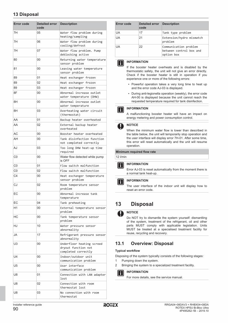
13 Disposal
Installer reference guide
90RRGA04~08DAV3 + RHBX04+08DA
ROTEX HPSU Bi-Bloc Ultra4P495262-1B – 2019.10
Error code Detailed errorcode
Description
7H 05 Water flow problem duringheating/sampling
7H 06 Water flow problem duringcooling/defrost
7H 07 Water flow problem. Pumpdeblocking active
80 00 Returning water temperaturesensor problem
81 00 Leaving water temperaturesensor problem
89 01 Heat exchanger frozen
89 02 Heat exchanger frozen
89 03 Heat exchanger frozen
8F 00 Abnormal increase outletwater temperature (DHW)
8H 00 Abnormal increase outletwater temperature
8H 03 Overheating water circuit(thermostat)
AA 01 Backup heater overheated
AA 02 External backup heateroverheated
AC 00 Booster heater overheated
AH 00 Tank disinfection functionnot completed correctly
AJ 03 Too long DHW heat-up timerequired
C0 00 Water flow detected while pumpis OFF
C0 01 Flow switch malfunction
C0 02 Flow switch malfunction
C4 00 Heat exchanger temperaturesensor problem
CJ 02 Room temperature sensorproblem
EC 00 Abnormal increase tanktemperature
EC 04 Tank preheating
H1 00 External temperature sensorproblem
HC 00 Tank temperature sensorproblem
HJ 10 Water pressure sensorabnormality
JA 17 Refrigerant pressure sensorabnormality
U3 00 Underfloor heating screeddryout function notcompleted correctly
U4 00 Indoor/outdoor unitcommunication problem
U5 00 User interfacecommunication problem
U8 01 Connection with LAN adapterlost
U8 02 Connection with roomthermostat lost
U8 03 No connection with roomthermostat
Error code Detailed errorcode
Description
UA 17 Tank type problem
UA 21 Extension/hydro mismatchproblem
UA 22 Communication problembetween control box andoption box
INFORMATIONIf the booster heater overheats and is disabled by thethermostatic safety, the unit will not give an error directly.Check if the booster heater is still in operation if youexperience one or more of the following errors:
▪ Powerful operation takes a very long time to heat upand the error code AJ-03 is displayed.
▪ During anti-legionella operation (weekly), the error codeAH-00 is displayed because the unit cannot reach therequested temperature required for tank disinfection.
INFORMATIONA malfunctioning booster heater will have an impact onenergy metering and power consumption control.
NOTICEWhen the minimum water flow is lower than described inthe table below, the unit will temporarily stop operation andthe user interface will display error 7H‑01. After some time,this error will reset automatically and the unit will resumeoperation.
Minimum required flow rate12 l/min
INFORMATIONError AJ-03 is reset automatically from the moment there isa normal tank heat-up.
INFORMATIONThe user interface of the indoor unit will display how toreset an error code.
13 DisposalNOTICEDo NOT try to dismantle the system yourself: dismantlingof the system, treatment of the refrigerant, oil and otherparts MUST comply with applicable legislation. UnitsMUST be treated at a specialised treatment facility forreuse, recycling and recovery.
13.1 Overview: DisposalTypical workflowDisposing of the system typically consists of the following stages:1 Pumping down the system.2 Bringing the system to a specialized treatment facility.
INFORMATIONFor more details, see the service manual.

13 Disposal
Installer reference guide
91RRGA04~08DAV3 + RHBX04+08DAROTEX HPSU Bi-Bloc Ultra4P495262-1B – 2019.10
13.2 To pump downExample: To protect the environment, pump down when relocatingthe unit or when disposing of the unit.
DANGER: RISK OF EXPLOSIONPump down – Refrigerant leakage. If you want to pumpdown the system, and there is a leak in the refrigerantcircuit:
▪ Do NOT use the unit's automatic pump down function,with which you can collect all refrigerant from thesystem into the outdoor unit. Possible consequence:Self-combustion and explosion of the compressorbecause of air going into the operating compressor.
▪ Use a separate recovery system so that the unit'scompressor does NOT have to operate.
NOTICEDuring pump down operation, stop the compressor beforeremoving the refrigerant piping. If the compressor is stillrunning and the stop valve is open during pump down, airwill be sucked into the system. Compressor breakdown ordamage to the system can result due to abnormal pressurein the refrigerant cycle.
Pump down operation will extract all refrigerant from the system intothe outdoor unit.
1 Remove the valve lid from the liquid stop valve and the gas stopvalve.
2 Install a manifold on the gas stop valve.
3 Carry out the forced cooling operation. See "13.3 To start andstop forced cooling" [4 91].
4 After 5 to 10 minutes (after only 1 or 2 minutes in case of verylow ambient temperatures (<−10°C)), close the liquid stop valvewith a hexagonal wrench.
5 Check on the manifold if the vacuum is reached.
6 After 2-3 minutes, close the gas stop valve and stop forcedcooling operation.
a
c
b
d
d
e
a Liquid stop valveb Closing directionc Hexagonal wrenchd Valve lide Gas stop valve
13.3 To start and stop forced cooling1 Turn OFF the power.
2 Remove the switch box cover.
2×
3 Remove the service PCB cover.
1 2 3 L N
L N PWR
HEATCOOL
4321
21
EDCBA
A
1
2
3
4
5
SW1SW3
SW2
SW5
SW6
SW4
S501
S502
S2
1×
4 Set DIP switches SW5 and SW6 to OFF.
5 Set DIP switch SW2 to COOL.
6 Reattach the service PCB cover.
7 Turn the power back ON. Proceed with the next step within 3minutes after restarting.
8 To start forced cooling, press the forced cooling operationswitch SW1.
9 To stop forced cooling, press the forced cooling operationswitch SW1 again.
10 Turn OFF the power, remove the switch box cover and servicePCB cover and set the DIP switches SW5, SW6 and SW2 backto their original position.
11 Reattach the service PCB cover and switch box cover and turnthe power back ON.
NOTICETake care that while running forced cooling operation, thewater temperature remains higher than 5°C (seetemperature read out of the indoor unit). You can achievethis, for example, by activating all fans of the fan coil units.
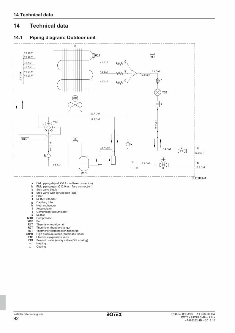
14 Technical data
Installer reference guide
92RRGA04~08DAV3 + RHBX04+08DA
ROTEX HPSU Bi-Bloc Ultra4P495262-1B – 2019.10
14 Technical data
14.1 Piping diagram: Outdoor unit
R2T7.0 CuT7.0 CuT
7.0 CuT7.0 CuT
7.0 CuT7.0 CuT
12.7 CuT
12.7 CuT
12.7
CuT 6.4 CuT
6.4 CuT6.4 CuT
6.4 CuT
4.0 CuT
4.0 CuT
9.5
CuT
15.9 CuT
3D110394
9.5 CuT
12.7 CuT
15.9 CuT
6.4
CuT
S1PH
Y1E
R1T
R3T
M1C
Y1S
4.0 CuT
M1F
b
ac
d
e
f
g
h
ijk
k
g
g
a Field piping (liquid: Ø6.4 mm flare connection)b Field piping (gas: Ø15.9 mm flare connection)c Stop valve (liquid)d Stop valve with service port (gas)e Filterf Muffler with filterg Capillary tubeh Heat exchangeri Accumulatorj Compressor accumulator
k MufflerM1C CompressorM1F FanR1T Thermistor (outdoor air)R2T Thermistor (heat exchanger)R3T Thermistor (compressor discharge)
S1PH High pressure switch (automatic reset)Y1E Electronic expansion valveY1S Solenoid valve (4‑way valve)(ON: cooling)
HeatingCooling
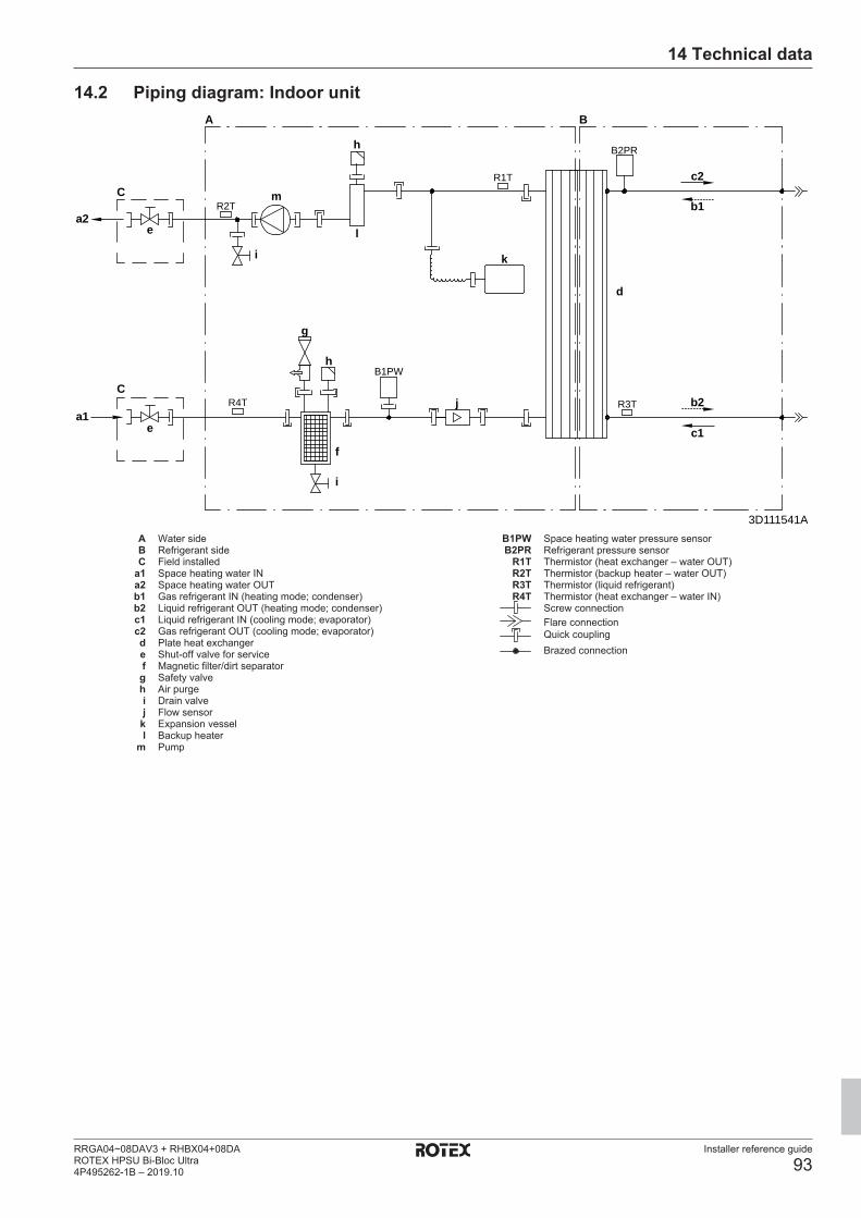
14 Technical data
Installer reference guide
93RRGA04~08DAV3 + RHBX04+08DAROTEX HPSU Bi-Bloc Ultra4P495262-1B – 2019.10
14.2 Piping diagram: Indoor unit
3D111541A
R2T
R4T
B1PW
B2PR
R1T
R3T
A
C
e
e
C
f
i
g
m
a2
a1
h
l
k
d
h
j
c1
b2
c2
b1
B
i
A Water sideB Refrigerant sideC Field installed
a1 Space heating water INa2 Space heating water OUTb1 Gas refrigerant IN (heating mode; condenser)b2 Liquid refrigerant OUT (heating mode; condenser)c1 Liquid refrigerant IN (cooling mode; evaporator)c2 Gas refrigerant OUT (cooling mode; evaporator)d Plate heat exchangere Shut-off valve for servicef Magnetic filter/dirt separatorg Safety valveh Air purgei Drain valvej Flow sensor
k Expansion vessell Backup heater
m Pump
B1PW Space heating water pressure sensorB2PR Refrigerant pressure sensor
R1T Thermistor (heat exchanger – water OUT)R2T Thermistor (backup heater – water OUT)R3T Thermistor (liquid refrigerant)R4T Thermistor (heat exchanger – water IN)
Screw connectionFlare connectionQuick couplingBrazed connection
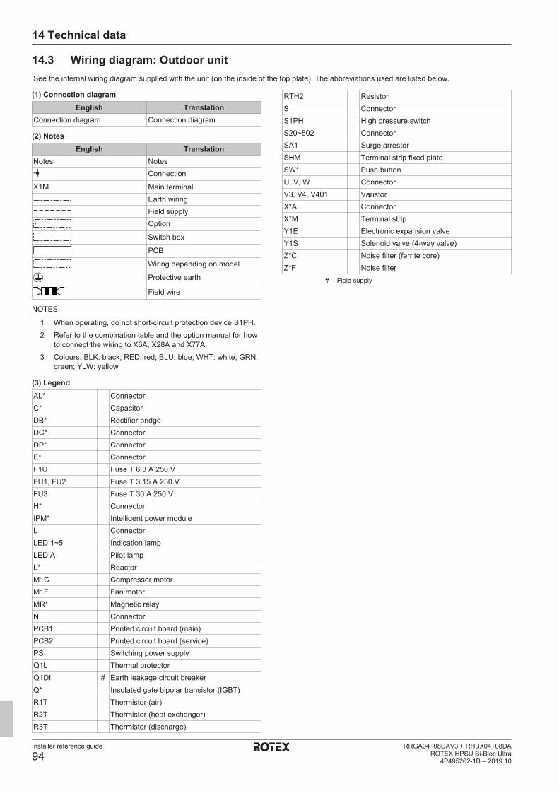
14 Technical data
Installer reference guide
94RRGA04~08DAV3 + RHBX04+08DA
ROTEX HPSU Bi-Bloc Ultra4P495262-1B – 2019.10
14.3 Wiring diagram: Outdoor unitSee the internal wiring diagram supplied with the unit (on the inside of the top plate). The abbreviations used are listed below.
(1) Connection diagramEnglish Translation
Connection diagram Connection diagram
(2) NotesEnglish Translation
Notes NotesConnection
X1M Main terminalEarth wiringField supplyOption
Switch box
PCB
Wiring depending on model
Protective earth
Field wire
NOTES:
1 When operating, do not short-circuit protection device S1PH.2 Refer to the combination table and the option manual for how
to connect the wiring to X6A, X28A and X77A.3 Colours: BLK: black; RED: red; BLU: blue; WHT: white; GRN:
green; YLW: yellow
(3) LegendAL* ConnectorC* CapacitorDB* Rectifier bridgeDC* ConnectorDP* ConnectorE* ConnectorF1U Fuse T 6.3 A 250 VFU1, FU2 Fuse T 3.15 A 250 VFU3 Fuse T 30 A 250 VH* ConnectorIPM* Intelligent power moduleL ConnectorLED 1~5 Indication lampLED A Pilot lampL* ReactorM1C Compressor motorM1F Fan motorMR* Magnetic relayN ConnectorPCB1 Printed circuit board (main)PCB2 Printed circuit board (service)PS Switching power supplyQ1L Thermal protectorQ1DI # Earth leakage circuit breakerQ* Insulated gate bipolar transistor (IGBT)R1T Thermistor (air)R2T Thermistor (heat exchanger)R3T Thermistor (discharge)
RTH2 ResistorS ConnectorS1PH High pressure switchS20~502 ConnectorSA1 Surge arrestorSHM Terminal strip fixed plateSW* Push buttonU, V, W ConnectorV3, V4, V401 VaristorX*A ConnectorX*M Terminal stripY1E Electronic expansion valveY1S Solenoid valve (4-way valve)Z*C Noise filter (ferrite core)Z*F Noise filter
# Field supply

14 Technical data
Installer reference guide
95RRGA04~08DAV3 + RHBX04+08DAROTEX HPSU Bi-Bloc Ultra4P495262-1B – 2019.10
14.4 Wiring diagram: Indoor unitSee the internal wiring diagram supplied with the unit (on the inside of the indoor unit upper front panel). The abbreviations used are listedbelow.
Notes to go through before starting the unitEnglish Translation
Notes to go through beforestarting the unit
Notes to go through beforestarting the unit
X1M Main terminalX2M Field wiring terminal for ACX5M Field wiring terminal for DCX6M Backup heater power supply
terminalX7M, X8M Booster heater power supply
terminalEarth wiringField supply
1 Several wiring possibilities
Option
Not mounted in switch box
Wiring depending on model
PCB
Note 1: Connection point of thepower supply for the BUH/BSHshould be foreseen outside theunit.
Note 1: Connection point of thepower supply for the backupheater/booster heater should beforeseen outside the unit.
Backup heater power supply Backup heater power supply 1N~, 230 V 1N~, 230 V 3~, 230 V 3~, 230 V 3N~, 400 V 3N~, 400 V
User installed options User installed options LAN adapter LAN adapter Domestic hot water tank Domestic hot water tank Remote user interface User interface used as room
thermostat Ext. indoor thermistor External indoor thermistor Ext outdoor thermistor External outdoor thermistor Digital I/O PCB Digital I/O PCB Demand PCB Demand PCB
Main LWT Main leaving water temperature On/OFF thermostat (wired) On/OFF thermostat (wired) On/OFF thermostat (wireless) On/OFF thermostat (wireless) Ext. thermistor External thermistor Heat pump convector Heat pump convector
Add LWT Additional leaving watertemperature
On/OFF thermostat (wired) On/OFF thermostat (wired) On/OFF thermostat (wireless) On/OFF thermostat (wireless) Ext. thermistor External thermistor Heat pump convector Heat pump convector
Position in switch boxEnglish Translation
Position in switch box Position in switch box
LegendA1P Main PCBA2P * On/OFF thermostat (PC=power circuit)
A3P * Heat pump convectorA4P * Digital I/O PCBA8P * Demand PCBA9P Status indicatorA10P MMI (= user interface connected to the
indoor unit) – Power supply unit PCBA11P MMI (= user interface connected to the
indoor unit) – Main PCBA12P MMI display PCBA13P * LAN adapterA14P * User interface used as room thermostat –
PCBA15P * Receiver PCB (wireless On/OFF thermostat)B1L Flow sensorB1PR Refrigerant pressure sensorB1PW Water pressure sensorBSK (A3P) Solar pump station relayCN* (A4P) * ConnectorDS1(A8P) * DIP switchE1H Backup heater element (1 kW)E2H Backup heater element (2 kW)E3H Backup heater element (3 kW)E4H * Booster heater (3 kW)E*P (A9P) Indication LEDF1B # Overcurrent fuse backup heaterF2B # Overcurrent fuse booster heaterF1T Thermal fuse backup heaterF1U, F2U (A4P) * Fuse 5 A 250 V for digital I/O PCBFU1 (A1P) Fuse T 5 A 250 V for PCBFU2 (A10P) Fuse T 1.6 A 250 V for PCBK1M, K2M Contactor backup heaterK3M * Contactor booster heaterK5M Safety contactor backup heaterK*R (A1P-A4P) Relay on PCBM1P Main supply pumpM2P # Domestic hot water pumpM2S # 2-way valve for cooling modeM3S * 3-way valve for floor heating/domestic hot
waterP1M MMI displayPC (A15P) * Power circuitPHC1 (A4P) * Optocoupler input circuitQ1L Thermal protector backup heaterQ2L * Thermal protector booster heaterQ4L # Safety thermostatQ*DI # Earth leakage circuit breakerR1H (A2P) * Humidity sensorR1T (A1P ) Outlet water heat exchanger thermistorR1T (A2P) * Ambient sensor On/OFF thermostatR1T (A14P) * Ambient sensor user interfaceR2T (A1P) Outlet backup heater thermistorR2T (A2P) * External sensor (floor or ambient)
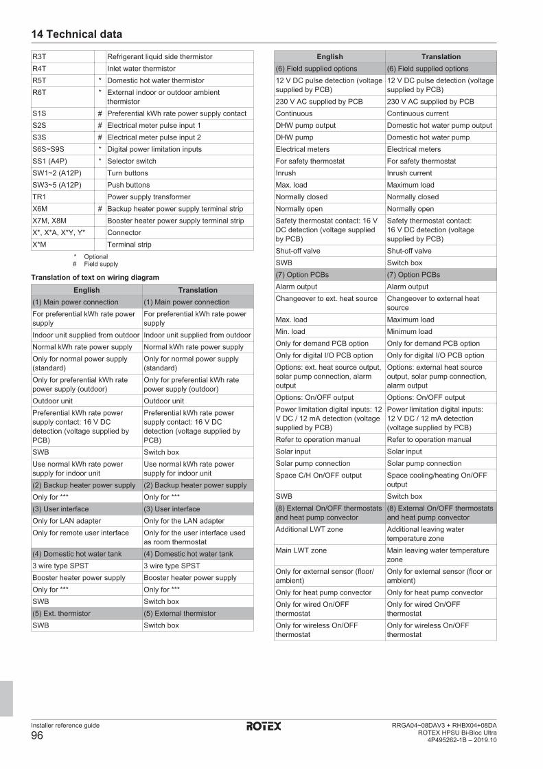
14 Technical data
Installer reference guide
96RRGA04~08DAV3 + RHBX04+08DA
ROTEX HPSU Bi-Bloc Ultra4P495262-1B – 2019.10
R3T Refrigerant liquid side thermistorR4T Inlet water thermistorR5T * Domestic hot water thermistorR6T * External indoor or outdoor ambient
thermistorS1S # Preferential kWh rate power supply contactS2S # Electrical meter pulse input 1S3S # Electrical meter pulse input 2S6S~S9S * Digital power limitation inputsSS1 (A4P) * Selector switchSW1~2 (A12P) Turn buttonsSW3~5 (A12P) Push buttonsTR1 Power supply transformerX6M # Backup heater power supply terminal stripX7M, X8M Booster heater power supply terminal stripX*, X*A, X*Y, Y* ConnectorX*M Terminal strip
* Optional# Field supply
Translation of text on wiring diagramEnglish Translation
(1) Main power connection (1) Main power connectionFor preferential kWh rate powersupply
For preferential kWh rate powersupply
Indoor unit supplied from outdoor Indoor unit supplied from outdoorNormal kWh rate power supply Normal kWh rate power supplyOnly for normal power supply(standard)
Only for normal power supply(standard)
Only for preferential kWh ratepower supply (outdoor)
Only for preferential kWh ratepower supply (outdoor)
Outdoor unit Outdoor unitPreferential kWh rate powersupply contact: 16 V DCdetection (voltage supplied byPCB)
Preferential kWh rate powersupply contact: 16 V DCdetection (voltage supplied byPCB)
SWB Switch boxUse normal kWh rate powersupply for indoor unit
Use normal kWh rate powersupply for indoor unit
(2) Backup heater power supply (2) Backup heater power supplyOnly for *** Only for ***(3) User interface (3) User interfaceOnly for LAN adapter Only for the LAN adapterOnly for remote user interface Only for the user interface used
as room thermostat(4) Domestic hot water tank (4) Domestic hot water tank3 wire type SPST 3 wire type SPSTBooster heater power supply Booster heater power supplyOnly for *** Only for ***SWB Switch box(5) Ext. thermistor (5) External thermistorSWB Switch box
English Translation(6) Field supplied options (6) Field supplied options12 V DC pulse detection (voltagesupplied by PCB)
12 V DC pulse detection (voltagesupplied by PCB)
230 V AC supplied by PCB 230 V AC supplied by PCBContinuous Continuous currentDHW pump output Domestic hot water pump outputDHW pump Domestic hot water pumpElectrical meters Electrical metersFor safety thermostat For safety thermostatInrush Inrush currentMax. load Maximum loadNormally closed Normally closedNormally open Normally openSafety thermostat contact: 16 VDC detection (voltage suppliedby PCB)
Safety thermostat contact:16 V DC detection (voltagesupplied by PCB)
Shut-off valve Shut-off valveSWB Switch box(7) Option PCBs (7) Option PCBsAlarm output Alarm outputChangeover to ext. heat source Changeover to external heat
sourceMax. load Maximum loadMin. load Minimum loadOnly for demand PCB option Only for demand PCB optionOnly for digital I/O PCB option Only for digital I/O PCB optionOptions: ext. heat source output,solar pump connection, alarmoutput
Options: external heat sourceoutput, solar pump connection,alarm output
Options: On/OFF output Options: On/OFF outputPower limitation digital inputs: 12V DC / 12 mA detection (voltagesupplied by PCB)
Power limitation digital inputs:12 V DC / 12 mA detection(voltage supplied by PCB)
Refer to operation manual Refer to operation manualSolar input Solar inputSolar pump connection Solar pump connectionSpace C/H On/OFF output Space cooling/heating On/OFF
outputSWB Switch box(8) External On/OFF thermostatsand heat pump convector
(8) External On/OFF thermostatsand heat pump convector
Additional LWT zone Additional leaving watertemperature zone
Main LWT zone Main leaving water temperaturezone
Only for external sensor (floor/ambient)
Only for external sensor (floor orambient)
Only for heat pump convector Only for heat pump convectorOnly for wired On/OFFthermostat
Only for wired On/OFFthermostat
Only for wireless On/OFFthermostat
Only for wireless On/OFFthermostat

14 Technical data
Installer reference guide
97RRGA04~08DAV3 + RHBX04+08DAROTEX HPSU Bi-Bloc Ultra4P495262-1B – 2019.10
Electrical connection diagramFor more details, please check the unit wiring.
2x0.75
(F1B)
3Gx2.5
A8P: X801M: 1-5
A8P: X801M: 2-5
A8P: X801M: 3-5
A8P: X801M: 4-5
X1M: 1-2-3
X2M: 5-6
X5M: 9-10
X9A (PCB A1P)
SPST:X2M: 12-13-14a
A4P: Y1-YCX2M: 7-9
A4P: X1-X2
X5M: 11-12
X2M: 1-2
X5M: 7-8
X5M: 5-6
X5M: 3-4
A4P: Y2-YCX2M: 7-9
A4P: Y3-YCX2M: 7-9
230 V
230 V
230 V
230 V
230 V
A3P: X11M: 3-4-5-6
4D111879D
A15P: X1M: H-C-comX2M: L-N A2P: X1M: 1-3
A2P: X1M: C-com-H
R2T
(F2B)
X1M: 1-2-3
X6M
3
3
3
1
1
2
2
230 V
- In case of signal cable: keep minimum distance to power cables >5 cm- Available heaters depending on model: see combination table
Notes:
X1M: L-N-earth
3 core
normal kWh rate power supply for indoor unit: 230 V
Field supply
booster heater power supply (3 kW): 400 V or 230 V + earth
BSK: A3P: 1-2 solar interlock
Cooling/heatingON/OFF output
Circulation pumpfor DHW
Ext. heat source (e.g. boiler)
Alarm indication
Only for *KSR3PA option
Only for KRCS01-1 or EKRSCA1
Electricity meterpulse input 2
Electricity meterpulse input 1
external thermistor(indoor or outdoor)
M2Sfor cooling mode
2-way valve
External sensor(floor or ambient)signal
Only for remote user interface
Only for *KRTETS2 core(3m included)
Only for(heat pump convector)
Only for *KRTW(wired room thermostat)
Only for *KRTR(wireless room thermostat)
A13P: P1-P2 LAN adapter
A14P: P1-P2 user interface
Optional parts
Optional partsExternal room thermostat / Heat pump convector(main and/or additional zone)
5 core for C/H operation4 core for H only operation
3 core for C/H operation2 core for H only operation
2 core
2 core
communication2x0.752 core
2 coresignal
2 coresignal
2 core
2 core
communication2x0.752 core
2 core
2 core
signal2 core
2 core
Only for *KRP1HB*
Changeover toext. heat source output
Alarm output
Solar input
Cooling/heatingON/OFF output
NO valve: X2M: 21-28NC valve: X2M: 21-29
main: X2M: 30-35add: X2M: 30-35a
main: X2M: 30-31-34-35add: X2M: 30-31-34a-35a
main: X2M: 30-34-35add: X2M: 30-34a-35a
or L1/L2/L3-N + earthor L1-L2 + earthX8M: L-N + earthor L1-L2-L3-N + earthor L-N + earthX6M: L1-L2-L3 + earth
X7M: L-N-earth
Only for *KRP1AHTA
2 core
3 core
signal
230 V
3 core
2 core
2 core
2 core
2 core
Power limitationdemand input 4
Power limitationdemand input 3
Power limitationdemand input 2
Power limitationdemand input 1
Field supply
M3S (when *KHW is installed)selection domestic hot water-floor heating
3-way valve
R5T - thermistorwater temperature
Booster heater/Q2L
Domestic hot water tank
3 core
Optional parts (*KHW*) 5 or 4 or 3core
backup heater power supply: 400 V or 230 V + earth
Safety thermostat
Preferential kWh rate power supply contact
230 V + earth
Only for preferential kWh rate power supply installationunit preferential kWh rate power supply:
2 core
3 core
3 core
3 core
unit power supply: 230 V + earthOnly for normal power supply installation
Field supplyIndoor unit
Standard part
Outdoor unit
Power supply
signal
signal
signal
signal
signal
signal
signal
signal
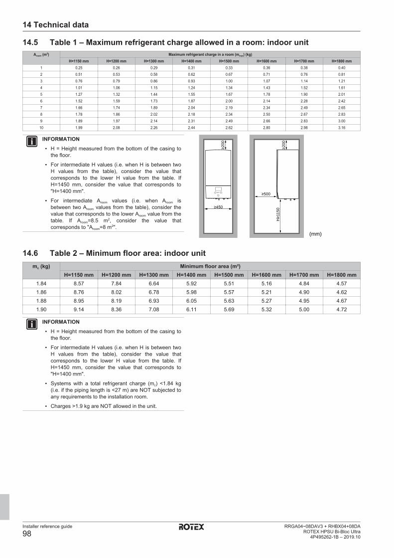
14 Technical data
Installer reference guide
98RRGA04~08DAV3 + RHBX04+08DA
ROTEX HPSU Bi-Bloc Ultra4P495262-1B – 2019.10
14.5 Table 1 – Maximum refrigerant charge allowed in a room: indoor unitAroom (m2) Maximum refrigerant charge in a room (mmax) (kg)
H=1150 mm H=1200 mm H=1300 mm H=1400 mm H=1500 mm H=1600 mm H=1700 mm H=1800 mm1 0.25 0.26 0.29 0.31 0.33 0.36 0.38 0.402 0.51 0.53 0.58 0.62 0.67 0.71 0.76 0.813 0.76 0.79 0.86 0.93 1.00 1.07 1.14 1.214 1.01 1.06 1.15 1.24 1.34 1.43 1.52 1.615 1.27 1.32 1.44 1.55 1.67 1.78 1.90 2.016 1.52 1.59 1.73 1.87 2.00 2.14 2.28 2.427 1.66 1.74 1.89 2.04 2.19 2.34 2.49 2.658 1.78 1.86 2.02 2.18 2.34 2.50 2.67 2.839 1.89 1.97 2.14 2.31 2.49 2.66 2.83 3.00
10 1.99 2.08 2.26 2.44 2.62 2.80 2.98 3.16
INFORMATION▪ H = Height measured from the bottom of the casing to
the floor.
▪ For intermediate H values (i.e. when H is between twoH values from the table), consider the value thatcorresponds to the lower H value from the table. IfH=1450 mm, consider the value that corresponds to"H=1400 mm".
▪ For intermediate Aroom values (i.e. when Aroom isbetween two Aroom values from the table), consider thevalue that corresponds to the lower Aroom value from thetable. If Aroom=8.5 m2, consider the value thatcorresponds to "Aroom=8 m2".
H≥1
150
≥200
≥200
≥500
(mm)
≥450
14.6 Table 2 – Minimum floor area: indoor unitmc (kg) Minimum floor area (m²)
H=1150 mm H=1200 mm H=1300 mm H=1400 mm H=1500 mm H=1600 mm H=1700 mm H=1800 mm1.84 8.57 7.84 6.64 5.92 5.51 5.16 4.84 4.571.86 8.76 8.02 6.78 5.98 5.57 5.21 4.90 4.621.88 8.95 8.19 6.93 6.05 5.63 5.27 4.95 4.671.90 9.14 8.36 7.08 6.11 5.69 5.32 5.00 4.72
INFORMATION▪ H = Height measured from the bottom of the casing to
the floor.
▪ For intermediate H values (i.e. when H is between twoH values from the table), consider the value thatcorresponds to the lower H value from the table. IfH=1450 mm, consider the value that corresponds to"H=1400 mm".
▪ Systems with a total refrigerant charge (mc) <1.84 kg(i.e. if the piping length is <27 m) are NOT subjected toany requirements to the installation room.
▪ Charges >1.9 kg are NOT allowed in the unit.

14 Technical data
Installer reference guide
99RRGA04~08DAV3 + RHBX04+08DAROTEX HPSU Bi-Bloc Ultra4P495262-1B – 2019.10
14.7 Table 3 – Minimum venting opening area for natural ventilation: indoor unitmc mmax dm=mc–mmax (kg) Minimum venting opening area (cm2)
H=1150 mm H=1200 mm H=1300 mm H=1400 mm H=1500 mm H=1600 mm H=1700 mm H=1800 mm1.9 0.1 1.80 538 515 495 477 461 446 433 4211.9 0.3 1.60 479 458 440 424 410 397 385 3741.9 0.5 1.40 419 401 385 371 359 347 337 3271.9 0.7 1.20 359 344 330 318 308 298 289 2811.9 0.9 1.00 299 287 275 265 256 248 241 2341.9 1.1 0.80 240 229 220 212 205 199 193 1871.9 1.3 0.60 180 172 165 159 154 149 145 1411.9 1.5 0.40 120 115 110 106 103 100 97 941.9 1.7 0.20 63 58 55 53 52 50 49 47
INFORMATION▪ H = Height measured from the bottom of the casing to
the floor.
▪ For intermediate H values (i.e. when H is between twoH values from the table), consider the value thatcorresponds to the lower H value from the table. IfH=1450 mm, consider the floor area that correspondsto "H=1400 mm".
▪ For intermediate dm values (i.e. when dm is betweentwo dm values from the table), consider the value thatcorresponds to the higher dm value from the table. Ifdm=1.55 kg, consider the value that corresponds to"dm=1.6 kg".

15 Glossary
Installer reference guide
100RRGA04~08DAV3 + RHBX04+08DA
ROTEX HPSU Bi-Bloc Ultra4P495262-1B – 2019.10
14.8 ESP curve: Indoor unitNote: A flow error will occur when the minimum water flow rate is notreached.
00 5 10 15 20 25 30 35
20
30C
40
50
60
70
10
4D112014B (l/min)
A (kPa)
A External static pressure in the space heating/cooling circuitB Water flow rate through the unit in the space heating/
cooling circuitC Operation range
Dashed lines: Operation area is extended to lower flow rates only incase the unit operates with heat pump only. (Not in startup, nobackup heater operation, no defrost operation.)
Notes:▪ Selecting a flow outside the operating area can damage the unit or
cause the unit to malfunction. See also the minimum andmaximum allowed water flow range in the technical specifications.
▪ Water quality must be according to EU directive 98/83 EC.
15 GlossaryDealer
Sales distributor for the product.
Authorised installerTechnical skilled person who is qualified to install theproduct.
UserPerson who is owner of the product and/or operates theproduct.
Applicable legislationAll international, European, national and local directives,laws, regulations and/or codes that are relevant andapplicable for a certain product or domain.
Service companyQualified company which can perform or coordinate therequired service to the product.
Installation manualInstruction manual specified for a certain product orapplication, explaining how to install, configure and maintainit.
Operation manualInstruction manual specified for a certain product orapplication, explaining how to operate it.
Maintenance instructionsInstruction manual specified for a certain product orapplication, which explains (if relevant) how to install,configure, operate and/or maintain the product orapplication.
AccessoriesLabels, manuals, information sheets and equipment that aredelivered with the product and that need to be installedaccording to the instructions in the accompanyingdocumentation.
Optional equipmentEquipment made or approved by ROTEX that can becombined with the product according to the instructions inthe accompanying documentation.
Field supplyEquipment NOT made by ROTEX that can be combinedwith the product according to the instructions in theaccompanying documentation.
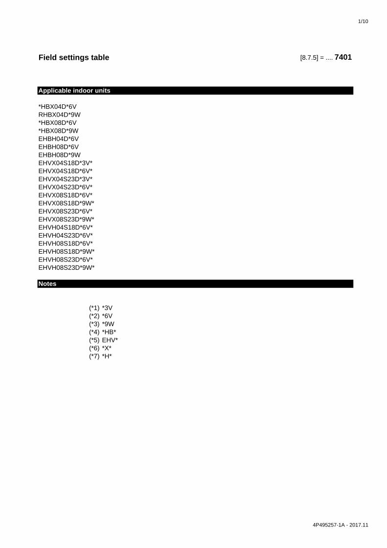
1/10
Field settings table [8.7.5] = .... 7401
Applicable indoor units
*HBX04D*6VRHBX04D*9W*HBX08D*6V*HBX08D*9WEHBH04D*6VEHBH08D*6VEHBH08D*9WEHVX04S18D*3V*EHVX04S18D*6V*EHVX04S23D*3V*EHVX04S23D*6V*EHVX08S18D*6V*EHVX08S18D*9W*EHVX08S23D*6V*EHVX08S23D*9W*EHVH04S18D*6V*EHVH04S23D*6V*EHVH08S18D*6V*EHVH08S18D*9W*EHVH08S23D*6V*EHVH08S23D*9W*
Notes
(*1) *3V(*2) *6V(*3) *9W(*4) *HB*(*5) EHV*(*6) *X*(*7) *H*
4P495257-1A - 2017.11

2/10
Breadcrumb Field code Setting name Range, stepDefault value
Date Value
Room└─ Antifrost
1.4.1 [2-06] R/W 0: Disabled1: Enabled
1.4.2 [2-05] R/W 4~16°C, step: 1°C12°C
└─ Setpoint range1.5.1 [3-07] R/W 12~18°C, step: 0,5°C
12°C1.5.2 [3-06] R/W 18~30°C, step: 0,5°C
30°C1.5.3 [3-09] R/W 15~25°C, step: 0,5°C
15°C1.5.4 [3-08] R/W 25~35°C, step: 0,5°C
35°CRoom1.6 [2-09] R/W -5~5°C, step: 0,5°C
0°C1.7 [2-0A] R/W -5~5°C, step: 0,5°C
0°CMain zone2.4 0: Fixed
1: WD heating, fixed cooling2: Weather dependent
└─ Heating WD curve2.5 [1-00] R/W -40~5°C, step: 1°C
-10°C2.5 [1-01] R/W 10~25°C, step: 1°C
15°C2.5 [1-02] R/W [9-01]~[9-00], step: 1°C
35°C2.5 [1-03] R/W [9-01]~min(45, [9-00])°C , step: 1°C
25°C└─ Cooling WD curve
2.6 [1-06] R/W 10~25°C, step: 1°C20°C
2.6 [1-07] R/W 25~43°C, step: 1°C35°C
2.6 [1-08] R/W [9-03]~[9-02]°C, step: 1°C22°C
2.6 [1-09] R/W [9-03]~[9-02]°C, step: 1°C18°C
Main zone2.7 [2-0C] R/W 0: Underfloor heating
1: Fancoil unit2: Radiator
└─ Setpoint range2.8.1 [9-01] R/W 15~37°C, step: 1°C
25°C2.8.2 [9-00] R/W [2-0C]=2:
37~65, step: 1°C55°C[2-0C]≠2:37~55, step: 1°C55°C
2.8.3 [9-03] R/W 5~18°C, step: 1°C5°C
2.8.4 [9-02] R/W 18~22°C, step: 1°C22°C
Main zone2.9 [C-07] R/W 0: LWT control
1: Ext RT control2: RT control
2.A [C-05] R/W 0: -1: 1 contact2: 2 contacts
└─ Delta T2.B.1 [1-0B] R/W 3~10°C, step: 1°C
5°C2.B.2 [1-0D] R/W 3~10°C, step: 1°C
5°C└─ Modulation
2.C.1 [8-05] R/W 0: No1: Yes
2.C.2 [8-06] R/W 0~10°C, step: 1°C5°C
└─ Shut off valve2.D.1 [F-0B] R/W 0: No
1: Yes2.D.2 [F-0C] R/W 0: No
1: YesAdditional zone3.4 0: Fixed
1: WD heating, fixed cooling2: Weather dependent
└─ Heating WD curve3.5 [0-00] R/W [9-05]~min(45,[9-06])°C, step: 1°C
35°C3.5 [0-01] R/W [9-05]~[9-06]°C, step: 1°C
50°C3.5 [0-02] R/W 10~25°C, step: 1°C
15°C3.5 [0-03] R/W -40~5°C, step: 1°C
-10°C└─ Cooling WD curve
3.6 [0-04] R/W [9-07]~[9-08]°C, step: 1°C8°C
3.6 [0-05] R/W [9-07]~[9-08]°C, step: 1°C12°C
3.6 [0-06] R/W 25~43°C, step: 1°C35°C
3.6 [0-07] R/W 10~25°C, step: 1°C20°C
Low ambient temp. for LWT add zone heating WD curve.
High ambient temp. for LWT add zone cooling WD curve.
Cooling minimum
Room setpoint
Heating minimum
Heating maximum
Cooling minimum
Cooling maximum
Heating maximum
High ambient temp. for LWT main zone cooling WD curve.
Leaving water value for low ambient temp. for LWT main zone cooling WD curve.
Room sensor offset
Room sensor offset
Low ambient temp. for LWT main zone heating WD curve.
High ambient temp. for LWT main zone heating WD curve.
High ambient temp. for LWT add zone heating WD curve.
Leaving water value for high ambient temp. for LWT add zone heating WD curve.
Cooling maximum
Delta T cooling
Modulation
Max modulation
Setpoint mode
Leaving water value for high ambient temp. for LWT add zone cooling WD curve.
Leaving water value for low ambient temp. for LWT add zone cooling WD curve.
Low ambient temp. for LWT add zone cooling WD curve.
Setpoint mode
Leaving water value for high ambient temp. for LWT main zone heating WD curve.
Low ambient temp. for LWT main zone cooling WD curve.
Field settings table
Thermostat type
Installer setting at variance with default value
Leaving water value for high ambient temp. for LWT main zone cooling WD curve.
Emitter type
Heating minimum
Leaving water value for low ambient temp. for LWT main zone heating WD curve.
Control
Activation
Delta T heating
Leaving water value for low ambient temp. for LWT add zone heating WD curve.
During cooling
During thermo
4P495257-1B - 2019.06 (#) Setting is not applicable for this unit.
(*1) *3V_(*2) *6V_(*3) *9W_(*4) *HB*_
(*5) EHV*_(*6) *X*_(*7) *H*
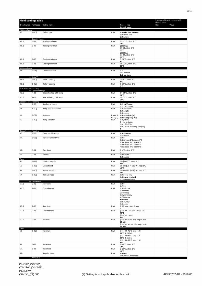
3/10
Breadcrumb Field code Setting name Range, stepDefault value
Date Value
Field settings table Installer setting at variance with default value
Additional zone3.7 [2-0D] R/W 0: Underfloor heating
1: Fancoil unit2: Radiator
└─ Setpoint range3.8.1 [9-05] R/W 15~37°C, step: 1°C
25°C3.8.2 [9-06] R/W [2-0D]=2:
37~65, step: 1°C55°C[2-0D]≠2:37~55, step: 1°C55°C
3.8.3 [9-07] R/W 5~18°C, step: 1°C5°C
3.8.4 [9-08] R/W 18~22°C, step: 1°C22°C
Additional zone3.A [C-06] R/W 0: -
1: 1 contact2: 2 contacts
└─ Delta T3.B.1 [1-0C] R/W 3~10°C, step: 1°C
5°C3.B.2 [1-0E] R/W 3~10°C, step: 1°C
5°CSpace heating / cooling
└─ Operation range4.3.1 [4-02] R/W 14~35°C, step: 1°C
22°C4.3.2 [F-01] R/W 10~35°C, step: 1°C
20°CSpace heating / cooling4.4 [7-02] R/W 0: 1 LWT zone
1: 2 LWT zones4.5 [F-0D] R/W 0: Continuous
1: Sample2: Request
4.6 [E-02] R/W (*6)R/O (*7)
0: Reversible (*6)1: Heating only (*7)
4.7 [9-0D] R/W 0~8, step:10 : No limitation1~4 : 50~80%5~8 : 50~80% during sampling6
Space heating / cooling4.9 [F-00] R/W 0: Restricted
1: Allowed4.A [D-03] R/W 0: No
1: increase 2°C, span 4°C2: increase 4°C, span 4°C3: increase 2°C, span 8°C4: increase 4°C, span 8°C
4.B [9-04] R/W 1~4°C, step: 1°C1°C
4.C [2-06] R/W 0: Disabled1: Enabled
Tank5.2 [6-0A] R/W 30~[6-0E]°C, step: 1°C
60°C5.3 [6-0B] R/W 30~min(50, [6-0E])°C, step: 1°C
45°C5.4 [6-0C] R/W 30~min(50, [6-0E])°C, step: 1°C
45°C5.6 [6-0D] R/W 0: Reheat only
1: Reheat + sched.2: Scheduled only
└─ Disinfection5.7.1 [2-01] R/W 0: No
1: Yes5.7.2 [2-00] R/W 0: Each day
1: Monday2: Tuesday3: Wednesday4: Thursday5: Friday6: Saturday7: Sunday
5.7.3 [2-02] R/W 0~23 hour, step: 1 hour1
5.7.4 [2-03] R/W [E-07]≠1 : 55~75°C, step: 5°C70°C[E-07]=1 : 60°C60°C
5.7.5 [2-04] R/W [E-07]≠1: 5~60 min, step: 5 min10 min[E-07]=1: 40~60 min, step: 5 min40 min
Tank5.8 [6-0E] R/W (*4) : 40~75°C, step: 1°C
60°C [E-07]=0(*4) : 40~80°C, step: 1°C80°C [E-07]=5(*5) : 40~60°C, step: 1°C60°C
5.9 [6-00] R/W 2~40°C, step: 1°C25°C
5.A [6-08] R/W 2~20°C, step: 1°C10°C
5.B R/W 0: Fixed1: Weather dependent
└─ WD curve
Activation
Pump operation mode
Antifrost
Start time
Pump outside range
Setpoint mode
Maximum
Heat up mode
Reheat setpoint
Eco setpoint
Heating minimum
Heating maximum
Delta T cooling
Unit type
Increase around 0°C
Cooling minimum
Cooling maximum
Space cooling OFF temp
Thermostat type
Emitter type
Comfort setpoint
Delta T heating
Space heating OFF temp
Pump limitation
Number of zones
Overshoot
Duration
Tank setpoint
Hysteresis
Operation day
Hysteresis
(*1) *3V_(*2) *6V_(*3) *9W_(*4) *HB*_(*5) EHV*_(*6) *X*_(*7) *H* (#) Setting is not applicable for this unit. 4P495257-1B - 2019.06

4/10
Breadcrumb Field code Setting name Range, stepDefault value
Date Value
Field settings table Installer setting at variance with default value
5.C [0-0B] R/W 35~[6-0E]°C, step: 1°C55°C
5.C [0-0C] R/W 45~[6-0E]°C, step: 1°C60°C
5.C [0-0D] R/W 10~25°C, step: 1°C15°C
5.C [0-0E] R/W -40~5°C, step: 1°C-10°C
Tank5.D [6-01] R/W 0~10°C, step: 1°C
2°CUser settings
└─ Quiet7.4.1 R/W 0: OFF
1: Quiet2: More quiet3: Most quiet4: Automatic
└─ Electricity price7.5.1 R/W 0,00~990/kWh
1/kWh7.5.2 R/W 0,00~990/kWh
1/kWh7.5.3 R/W 0,00~990/kWh
1/kWhUser settings7.6 R/W 0,00~990/kWh
0,00~290/MBtu1,0/kWh
Installer settings└─ Configuration wizard
└─ System9.1 [E-03] R/O 2: 3V (*1)
3: 6V (*2)4: 9W (*3)
9.1 [E-05][E-06][E-07]
R/W 0: No DHW (*4)2: EKHW (*4)3: Integrated (*5)7: EKHWP (*4)
9.1 [4-06] R/W 0: Manual1: Automatic
9.1 [7-02] R/W 0: Single zone1: Dual zone
└─ Backup heater9.1 [5-0D] R/W (*2)
R/O (*1) (*3)
0: 230V, 1~ (*1) (*2)1: 230V, 3~ (*2)2: 400V, 3~ (*3)
9.1 [4-0A] R/W 0: 1 (*1)1: 1/1+2 (*2) (*3)2: 1/23: 1/2 + 1/1+2 in emergency
9.1 [6-03] R/W 0~10kW, step: 0,2kW2kW (*2)3kW (*1)(*3)
9.1 [6-04] R/O (*1)R/W (*2) (*3)
0~10kW, step: 0,2kW0kW (*1)4kW (*2)6kW (*3)
└─ Main zone9.1 [2-0C] R/W 0: Underfloor heating
1: Fancoil unit2: Radiator
9.1 [C-07] R/W 0: LWT control1: Ext RT control2: RT control
9.1 R/W 0: Fixed1: WD heating, fixed cooling2: Weather dependent
9.1 R/W 0: No1: Yes
9.1 [1-00] R/W -40~5°C, step: 1°C-10°C
9.1 [1-01] R/W 10~25°C, step: 1°C15°C
9.1 [1-02] R/W [9-01]~[9-00], step: 1°C35°C
9.1 [1-03] R/W [9-01]~min(45, [9-00])°C , step: 1°C25°C
9.1 [1-06] R/W 10~25°C, step: 1°C20°C
9.1 [1-07] R/W 25~43°C, step: 1°C35°C
9.1 [1-08] R/W [9-03]~[9-02]°C, step: 1°C22°C
9.1 [1-09] R/W [9-03]~[9-02]°C, step: 1°C18°C
└─ Additional zone9.1 [2-0D] R/W 0: Underfloor heating
1: Fancoil unit2: Radiator
9.1 R/W 0: Fixed1: WD heating, fixed cooling2: Weather dependent
9.1 R/W 0: No1: Yes
9.1 [0-00] R/W [9-05]~min(45,[9-06])°C, step: 1°C35°C
9.1 [0-01] R/W [9-05]~[9-06]°C, step: 1°C50°C
9.1 [0-02] R/W 10~25°C, step: 1°C15°C
9.1 [0-03] R/W -40~5°C, step: 1°C-10°C
Leaving water value for high ambient temp. for LWT main zone cooling WD curve.
Leaving water value for high ambient temp. for LWT add zone heating WD curve.
Leaving water value for low ambient temp. for LWT add zone heating WD curve.
High ambient temp. for LWT add zone heating WD curve.
Low ambient temp. for LWT add zone heating WD curve.
Schedule
Emitter type
Setpoint mode
Leaving water value for high ambient temp. for LWT main zone heating WD curve.
Low ambient temp. for LWT main zone cooling WD curve.
Control
Setpoint mode
Schedule
Leaving water value for low ambient temp. for LWT main zone cooling WD curve.
High ambient temp. for LWT main zone cooling WD curve.
Low ambient temp. for LWT main zone heating WD curve.
High ambient temp. for LWT main zone heating WD curve.
Leaving water value for low ambient temp. for LWT main zone heating WD curve.
Number of zones
Voltage
Configuration
Capacity step 1
Additional capacity step 2
Emitter type
Emergency
Margin
Activation
High
Medium
Low
Leaving water value for low ambient temp. for DHW WD curve.
Gas price
BUH type
Domestic hot water
Leaving water value for high ambient temp. for DHW WD curve.
High ambient temp. for DHW WD curve.
Low ambient temp. for DHW WD curve.
4P495257-1B - 2019.06 (#) Setting is not applicable for this unit.
(*1) *3V_(*2) *6V_(*3) *9W_(*4) *HB*_
(*5) EHV*_(*6) *X*_(*7) *H*

5/10
Breadcrumb Field code Setting name Range, stepDefault value
Date Value
Field settings table Installer setting at variance with default value
9.1 [0-04] R/W [9-07]~[9-08]°C, step: 1°C8°C
9.1 [0-05] R/W [9-07]~[9-08]°C, step: 1°C12°C
9.1 [0-06] R/W 25~43°C, step: 1°C35°C
9.1 [0-07] R/W 10~25°C, step: 1°C20°C
└─ Tank9.1 [6-0D] R/W 0: Reheat only
1: Reheat + sched.2: Scheduled only
9.1 [6-0A] R/W 30~[6-0E]°C, step: 1°C60°C
9.1 [6-0B] R/W 30~min(50, [6-0E])°C, step: 1°C45°C
9.1 [6-0C] R/W 30~min(50, [6-0E])°C, step: 1°C45°C
└─ Domestic hot water9.2.1 [E-05]
[E-06][E-07]
R/W 0: No DHW (*4)2: EKHW (*4)3: Integrated (*5)7: EKHWP (*4)
9.2.2 [D-02] R/W 0: No1: Secondary rtrn2: Disinf. Shunt
9.2.4 [D-07] R/W 0: No1: Yes
└─ Back up heater9.3.1 [E-03] R/O 2: 3V (*1)
3: 6V (*2)4: 9W (*3)
9.3.2 [5-0D] R/W (*2)R/O (*1) (*3)
0: 230V, 1~ (*1) (*2)1: 230V, 3~ (*2)2: 400V, 3~ (*3)
9.3.3 [4-0A] R/W 0: 1 (*1)1: 1/1+2 (*2) (*3)2: 1/23: 1/2 + 1/1+2 in emergency
9.3.4 [6-03] R/W 0~10kW, step: 0,2kW2kW (*2)3kW (*1)(*3)
9.3.5 [6-04] R/O (*1)R/W (*2) (*3)
0~10kW, step: 0,2kW0kW (*1)4kW (*2)6kW (*3)
9.3.6 [5-00] R/W 0: Allowed1: Not allowed
9.3.7 [5-01] R/W -15~35°C, step: 1°C0°C
9.3.8 [4-00] R/W 0: Disabled1: Enabled2: Only DHW
└─ Booster heater9.4.1 [6-02] R/W 0~10kW, step: 0,2kW
3kW (*4)0kW (*5)
9.4.3 [8-03] R/W 20~95 min, step: 5 min50 min
9.4.4 [4-03] R/W 0: Restricted1: Allowed2: Overlap3: Compressor off4: Legionella only
Installer settings9.5 [4-06] R/W 0: Manual
1: Automatic└─ Balancing
9.6.1 [5-02] R/W 0: Disabled1: Enabled
9.6.2 [5-03] R/W -15~35°C, step: 1°C0°C
9.6.3 [5-04] R/W 0~20°C, step: 1°C10°C
9.6.4 [8-02] R/W 0~10 hour, step: 0,5 hour0,5 hour [E-07]=1 3 hour [E-07]≠1
9.6.5 [8-00] R/W 0~20 min, step 1 min1 min
9.6.6 [8-01] R/W 5~95 min, step: 5 min30 min
9.6.7 [8-04] R/W 0~95 min, step: 5 min95 min
Installer settings9.7 [4-04] 0: Intermittent
1: Continuous2: Off
└─ Benefit kWh power supply9.8.1 [D-01] R/W 0: No
1: Active open2: Active closed3: Safety thermostat
9.8.2 [D-00] R/W 0: None1: BSH only2: BUH only3: All heaters
9.8.3 [D-05] R/W 0: Forced off1: As normal
└─ Power consumption control9.9.1 [4-08] R/W 0: No limitation
1: Continuous2: Digital inputs
Allow pump
Power consumption control
Minimum running timer
Maximum running timer
Additional timer
Water pipe freeze prevention
Benefit kWh power supply
Allow heater
Operation
Emergency
Space heating priority
Priority temperature
Offset BSH setpoint
Anti-recycle timer
Additional capacity step 2
Equilibrium
Equilibrium temperature
Operation
Capacity
BSH eco timer
Eco setpoint
Reheat setpoint
Domestic hot water
DHW pump
Solar
BUH type
Voltage
Configuration
Capacity step 1
Leaving water value for high ambient temp. for LWT add zone cooling WD curve.
Leaving water value for low ambient temp. for LWT add zone cooling WD curve.
High ambient temp. for LWT add zone cooling WD curve.
Low ambient temp. for LWT add zone cooling WD curve.
Heat up mode
Comfort setpoint
(*1) *3V_(*2) *6V_(*3) *9W_(*4) *HB*_(*5) EHV*_(*6) *X*_(*7) *H* (#) Setting is not applicable for this unit. 4P495257-1B - 2019.06
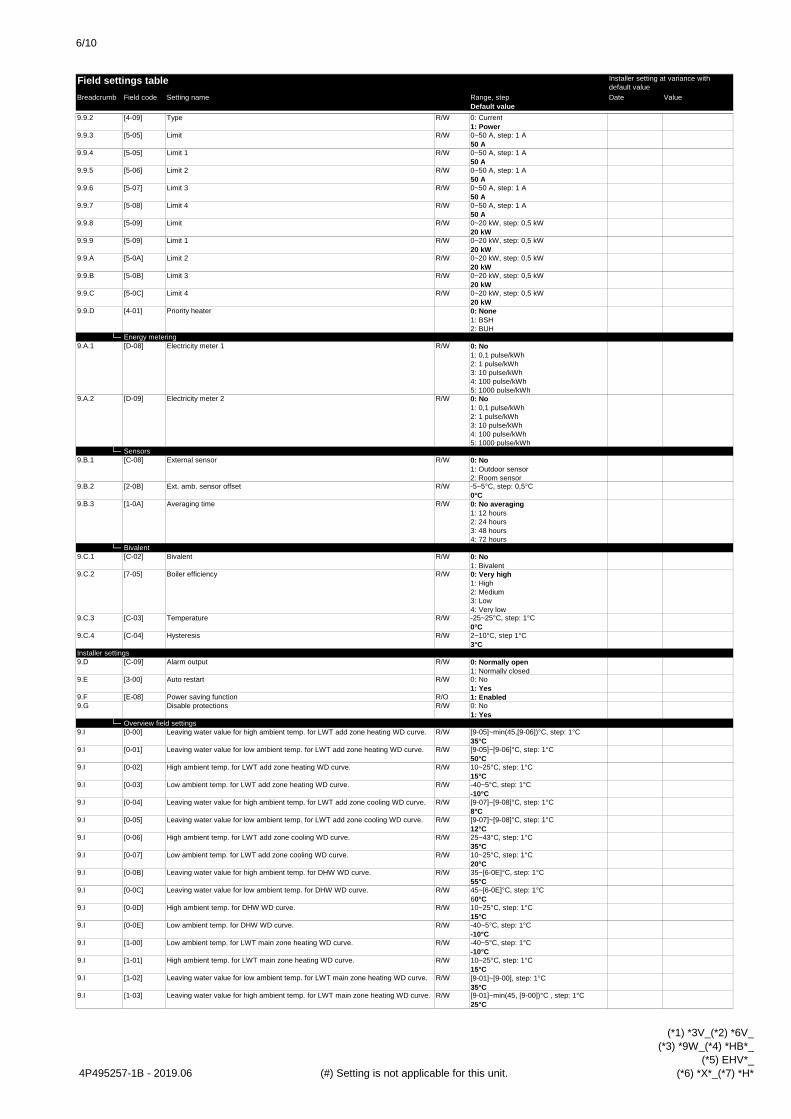
6/10
Breadcrumb Field code Setting name Range, stepDefault value
Date Value
Field settings table Installer setting at variance with default value
9.9.2 [4-09] R/W 0: Current1: Power
9.9.3 [5-05] R/W 0~50 A, step: 1 A50 A
9.9.4 [5-05] R/W 0~50 A, step: 1 A50 A
9.9.5 [5-06] R/W 0~50 A, step: 1 A50 A
9.9.6 [5-07] R/W 0~50 A, step: 1 A50 A
9.9.7 [5-08] R/W 0~50 A, step: 1 A50 A
9.9.8 [5-09] R/W 0~20 kW, step: 0,5 kW20 kW
9.9.9 [5-09] R/W 0~20 kW, step: 0,5 kW20 kW
9.9.A [5-0A] R/W 0~20 kW, step: 0,5 kW20 kW
9.9.B [5-0B] R/W 0~20 kW, step: 0,5 kW20 kW
9.9.C [5-0C] R/W 0~20 kW, step: 0,5 kW20 kW
9.9.D [4-01] 0: None1: BSH2: BUH
└─ Energy metering9.A.1 [D-08] R/W 0: No
1: 0,1 pulse/kWh2: 1 pulse/kWh3: 10 pulse/kWh4: 100 pulse/kWh5: 1000 pulse/kWh
9.A.2 [D-09] R/W 0: No1: 0,1 pulse/kWh2: 1 pulse/kWh3: 10 pulse/kWh4: 100 pulse/kWh5: 1000 pulse/kWh
└─ Sensors9.B.1 [C-08] R/W 0: No
1: Outdoor sensor2: Room sensor
9.B.2 [2-0B] R/W -5~5°C, step: 0,5°C0°C
9.B.3 [1-0A] R/W 0: No averaging1: 12 hours2: 24 hours3: 48 hours4: 72 hours
└─ Bivalent9.C.1 [C-02] R/W 0: No
1: Bivalent9.C.2 [7-05] R/W 0: Very high
1: High2: Medium3: Low4: Very low
9.C.3 [C-03] R/W -25~25°C, step: 1°C0°C
9.C.4 [C-04] R/W 2~10°C, step 1°C3°C
Installer settings9.D [C-09] R/W 0: Normally open
1: Normally closed9.E [3-00] R/W 0: No
1: Yes9.F [E-08] R/O 1: Enabled9.G R/W 0: No
1: Yes└─ Overview field settings
9.I [0-00] R/W [9-05]~min(45,[9-06])°C, step: 1°C35°C
9.I [0-01] R/W [9-05]~[9-06]°C, step: 1°C50°C
9.I [0-02] R/W 10~25°C, step: 1°C15°C
9.I [0-03] R/W -40~5°C, step: 1°C-10°C
9.I [0-04] R/W [9-07]~[9-08]°C, step: 1°C8°C
9.I [0-05] R/W [9-07]~[9-08]°C, step: 1°C12°C
9.I [0-06] R/W 25~43°C, step: 1°C35°C
9.I [0-07] R/W 10~25°C, step: 1°C20°C
9.I [0-0B] R/W 35~[6-0E]°C, step: 1°C55°C
9.I [0-0C] R/W 45~[6-0E]°C, step: 1°C60°C
9.I [0-0D] R/W 10~25°C, step: 1°C15°C
9.I [0-0E] R/W -40~5°C, step: 1°C-10°C
9.I [1-00] R/W -40~5°C, step: 1°C-10°C
9.I [1-01] R/W 10~25°C, step: 1°C15°C
9.I [1-02] R/W [9-01]~[9-00], step: 1°C35°C
9.I [1-03] R/W [9-01]~min(45, [9-00])°C , step: 1°C25°C
Leaving water value for low ambient temp. for LWT add zone heating WD curve.
High ambient temp. for LWT add zone heating WD curve.
Low ambient temp. for LWT add zone heating WD curve.
Leaving water value for high ambient temp. for LWT add zone cooling WD curve.
Leaving water value for low ambient temp. for LWT add zone cooling WD curve.
Leaving water value for high ambient temp. for DHW WD curve.
Leaving water value for low ambient temp. for DHW WD curve.
High ambient temp. for DHW WD curve.
Low ambient temp. for DHW WD curve.
Auto restart
Power saving functionDisable protections
Leaving water value for high ambient temp. for LWT add zone heating WD curve.
High ambient temp. for LWT add zone cooling WD curve.
Low ambient temp. for LWT add zone cooling WD curve.
Leaving water value for high ambient temp. for LWT main zone heating WD curve.
Low ambient temp. for LWT main zone heating WD curve.
High ambient temp. for LWT main zone heating WD curve.
Averaging time
Bivalent
Boiler efficiency
Temperature
Hysteresis
Alarm output
Leaving water value for low ambient temp. for LWT main zone heating WD curve.
Limit 4
Priority heater
Electricity meter 1
Electricity meter 2
External sensor
Ext. amb. sensor offset
Limit 3
Limit 4
Limit
Limit 1
Limit 2
Limit 3
Type
Limit
Limit 1
Limit 2
4P495257-1B - 2019.06 (#) Setting is not applicable for this unit.
(*1) *3V_(*2) *6V_(*3) *9W_(*4) *HB*_
(*5) EHV*_(*6) *X*_(*7) *H*

7/10
Breadcrumb Field code Setting name Range, stepDefault value
Date Value
Field settings table Installer setting at variance with default value
9.I [1-04] R/W 0: Disabled1: Enabled
9.I [1-05] R/W 0: Disabled1: Enabled
9.I [1-06] R/W 10~25°C, step: 1°C20°C
9.I [1-07] R/W 25~43°C, step: 1°C35°C
9.I [1-08] R/W [9-03]~[9-02]°C, step: 1°C22°C
9.I [1-09] R/W [9-03]~[9-02]°C, step: 1°C18°C
9.I [1-0A] R/W 0: No averaging1: 12 hours2: 24 hours3: 48 hours4: 72 hours
9.I [1-0B] R/W 3~10°C, step: 1°C5°C
9.I [1-0C] R/W 3~10°C, step: 1°C5°C
9.I [1-0D] R/W 3~10°C, step: 1°C5°C
9.I [1-0E] R/W 3~10°C, step: 1°C5°C
9.I [2-00] R/W 0: Each day1: Monday2: Tuesday3: Wednesday4: Thursday5: Friday6: Saturday7: Sunday
9.I [2-01] R/W 0: No1: Yes
9.I [2-02] R/W 0~23 hour, step: 1 hour1
9.I [2-03] R/W [E-07]≠1 : 55~75°C, step: 5°C70°C[E-07]=1 : 60°C60°C
9.I [2-04] R/W [E-07]≠1: 5~60 min, step: 5 min10 min[E-07]=1: 40~60 min, step: 5 min40 min
9.I [2-05] R/W 4~16°C, step: 1°C12°C
9.I [2-06] R/W 0: Disabled1: Enabled
9.I [2-09] R/W -5~5°C, step: 0,5°C0°C
9.I [2-0A] R/W -5~5°C, step: 0,5°C0°C
9.I [2-0B] R/W -5~5°C, step: 0,5°C0°C
9.I [2-0C] R/W 0: Underfloor heating1: Fancoil unit2: Radiator
9.I [2-0D] R/W 0: Underfloor heating1: Fancoil unit2: Radiator
9.I [3-00] R/W 0: No1: Yes
9.I [3-01] 09.I [3-02] 19.I [3-03] 49.I [3-04] 29.I [3-05] 19.I [3-06] R/W 18~30°C, step: 0,5°C
30°C9.I [3-07] R/W 12~18°C, step: 0,5°C
12°C9.I [3-08] R/W 25~35°C, step: 0,5°C
35°C9.I [3-09] R/W 15~25°C, step: 0,5°C
15°C9.I [4-00] R/W 0: Disabled
1: Enabled2: Only DHW
9.I [4-01] R/W 0: None1: BSH2: BUH
9.I [4-02] R/W 14~35°C, step: 1°C22°C
9.I [4-03] R/W 0: Restricted1: Allowed2: Overlap3: Compressor off4: Legionella only
9.I [4-04] 0: Intermittent1: Continuous2: Off
9.I [4-05] 09.I [4-06] R/W 0: Manual
1: Automatic9.I [4-08] R/W 0: No limitation
1: Continuous2: Digital inputs
9.I [4-09] R/W 0: Current1: Power
--
Is auto restart of the unit allowed?
--
What is the disinfection target temperature?
What emitter type is connected to the main LWT zone?
What emitter type is connected to the additional LWT zone?
What is the minimum desired room temperature in cooling?
How long must the tank temperature be maintained?
Room antifrost temperature
Room frost protection
Adjust the offset on the measured room temperature
Adjust the offset on the measured room temperature
What is the required offset on the measured outdoor temp.?
Low ambient temp. for LWT main zone cooling WD curve.
When should the disinfection function be executed?
Should the disinfection function be executed?
When should the disinfection function start?
What is the mimimum desired room temperature in heating?
What is the maximum desired room temperature in cooling?
What is the BUH operation mode?
Which electric heater has priority?
Which power limitation mode is required on the system?
Which power limitation type is required?
--Emergency
Operation permission of the booster heater.
Below which outdoor temperature is heating allowed?
------What is the maximum desired room temperature in heating?
Weather dependent cooling of the main leaving water temperature zone.
Weather dependent cooling of the additional leaving water temperature zone
Leaving water value for high ambient temp. for LWT main zone cooling WD curve.
What is the averaging time for the outdoor temp?
High ambient temp. for LWT main zone cooling WD curve.
Leaving water value for low ambient temp. for LWT main zone cooling WD curve.
What is the desired delta T in heating for the main zone?
What is the desired delta T in cooling for the main zone?
What is the desired delta T in cooling for the additional zone?
What is the desired delta T in heating for the additional zone?
Water pipe freeze prevention
(*1) *3V_(*2) *6V_(*3) *9W_(*4) *HB*_(*5) EHV*_(*6) *X*_(*7) *H* (#) Setting is not applicable for this unit. 4P495257-1B - 2019.06

8/10
Breadcrumb Field code Setting name Range, stepDefault value
Date Value
Field settings table Installer setting at variance with default value
9.I [4-0A] R/W 0: 1 (*1)1: 1/1+2 (*2) (*3)2: 1/23: 1/2 + 1/1+2 in emergency
9.I [4-0B] R/W 1~10°C, step: 0,5°C1°C
9.I [4-0D] R/W 1~10°C, step: 0,5°C3°C
9.I [5-00] R/W 0: Allowed1: Not allowed
9.I [5-01] R/W -15~35°C, step: 1°C0°C
9.I [5-02] R/W 0: Disabled1: Enabled
9.I [5-03] R/W -15~35°C, step: 1°C0°C
9.I [5-04] R/W 0~20°C, step: 1°C10°C
9.I [5-05] R/W 0~50 A, step: 1 A50 A
9.I [5-06] R/W 0~50 A, step: 1 A50 A
9.I [5-07] R/W 0~50 A, step: 1 A50 A
9.I [5-08] R/W 0~50 A, step: 1 A50 A
9.I [5-09] R/W 0~20 kW, step: 0,5 kW20 kW
9.I [5-0A] R/W 0~20 kW, step: 0,5 kW20 kW
9.I [5-0B] R/W 0~20 kW, step: 0,5 kW20 kW
9.I [5-0C] R/W 0~20 kW, step: 0,5 kW20 kW
9.I [5-0D] R/W (*2)R/O (*1) (*3)
0: 230V, 1~ (*1) (*2)1: 230V, 3~ (*2)2: 400V, 3~ (*3)
9.I [5-0E] 19.I [6-00] R/W 2~40°C, step: 1°C
25°C9.I [6-01] R/W 0~10°C, step: 1°C
2°C9.I [6-02] R/W 0~10kW, step: 0,2kW
3kW9.I [6-03] R/W 0~10kW, step: 0,2kW
2kW (*2)3kW (*1)(*3)
9.I [6-04] R/O (*1)R/W (*2) (*3)
0~10kW, step: 0,2kW0kW (*1)4kW (*2)6kW (*3)
9.I [6-05] 09.I [6-06] 09.I [6-07] R/W 0~200W, step: 10W
0W9.I [6-08] R/W 2~20°C, step: 1°C
10°C9.I [6-09] 09.I [6-0A] R/W 30~[6-0E]°C, step: 1°C
60°C9.I [6-0B] R/W 30~min(50, [6-0E])°C, step: 1°C
45°C9.I [6-0C] R/W 30~min(50, [6-0E])°C, step: 1°C
45°C9.I [6-0D] R/W 0: Reheat only
1: Reheat + sched.2: Scheduled only
9.I [6-0E] R/W (*4) : 40~75°C, step: 1°C60°C [E-07]=0(*4) : 40~80°C, step: 1°C80°C [E-07]=5(*5) : 40~60°C, step: 1°C60°C
9.I [7-00] R/W 0~4°C, step: 1°C0°C
9.I [7-01] R/W 2~40°C, step: 1°C2°C
9.I [7-02] R/W 0: 1 LWT zone1: 2 LWT zones
9.I [7-03] 2,59.I [7-04] 09.I [7-05] R/W 0: Very high
1: High2: Medium3: Low4: Very low
9.I [8-00] R/W 0~20 min, step 1 min1 min
9.I [8-01] R/W 5~95 min, step: 5 min30 min
9.I [8-02] R/W 0~10 hour, step: 0,5 hour0,5 hour [E-07]=1 3 hour [E-07]≠1
9.I [8-03] R/W 20~95 min, step: 5 min50 min
9.I [8-04] R/W 0~95 min, step: 5 min95 min
9.I [8-05] R/W 0: No1: Yes
9.I [8-06] R/W 0~10°C, step: 1°C5°C
9.I [8-07] R/W [9-03]~[9-02], step: 1°C18°C
Booster heater delay timer.
Additional running time for the maximum running time.
Allow modulation of the LWT to control the room temp?
Leaving water temperature maximum modulation.
What is the desired comfort main LWT in cooling?
----Boiler efficiency
Minimum running time for domestic hot water operation.
Maximum running time for domestic hot water operation.
Anti-recycling time.
What is the desired reheat temperature?
What is the desired DHW production type?
What is the maximum temperature setpoint?
Domestic hot water booster heater overshoot temperature.
Domestic hot water booster heater hysteresis.
How many leaving water temperature zones are there?
What is the hysteresis to be used in reheat mode?
--What is the capacity of the bottom plate heater?
--What is the desired comfort storage temperature?
What is the desired eco storage temperature?
--
Backup heater voltage
What is the requested limit for DI2?
What is the requested limit for DI3?
What is the requested limit for DI4?
What is the equilibrium temperature for the building?
What is the requested limit for DI2?
What is the requested limit for DI3?
What is the requested limit for DI4?
What is the requested limit for DI1?
Backup heater configuration
Automatic cooling/heating changeover hysteresis.
Automatic cooling/heating changeover offset.
Is backup heater operation allowed above equilibrium temperature during space heating operation?
--
The temperature difference determining the heat pump ON temperature.
The temperature difference determining the heat pump OFF temperature.
What is the capacity of the booster heater?
What is the capacity of the backup heater step 1?
What is the capacity of the backup heater step 2?
Space heating priority temperature.
Set point correction for domestic hot water temperature.
What is the requested limit for DI1?
Space heating priority.
4P495257-1B - 2019.06 (#) Setting is not applicable for this unit.
(*1) *3V_(*2) *6V_(*3) *9W_(*4) *HB*_
(*5) EHV*_(*6) *X*_(*7) *H*

9/10
Breadcrumb Field code Setting name Range, stepDefault value
Date Value
Field settings table Installer setting at variance with default value
9.I [8-08] R/W [9-03]~[9-02], step: 1°C20°C
9.I [8-09] R/W [9-01]~[9-00], step: 1°C35°C
9.I [8-0A] R/W [9-01]~[9-00], step: 1°C33°C
9.I [8-0B] 139.I [8-0C] 109.I [8-0D] 169.I [9-00] R/W [2-0C]=2:
37~65, step: 1°C55°C[2-0C]≠2:37~55, step: 1°C55°C
9.I [9-01] R/W 15~37°C, step: 1°C25°C
9.I [9-02] R/W 18~22°C, step: 1°C22°C
9.I [9-03] R/W 5~18°C, step: 1°C5°C
9.I [9-04] R/W 1~4°C, step: 1°C1°C
9.I [9-05] R/W 15~37°C, step: 1°C25°C
9.I [9-06] R/W [2-0D]=2:37~65, step: 1°C55°C[2-0D]≠2:37~55, step: 1°C55°C
9.I [9-07] R/W 5~18°C, step: 1°C5°C
9.I [9-08] R/W 18~22°C, step: 1°C22°C
9.I [9-0C] R/W 1~6°C, step: 0,5°C1 °C
9.I [9-0D] R/W 0~8, step:10 : No limitation1~4 : 50~80%5~8 : 50~80% during sampling6
9.I [9-0E] 69.I [C-00] R/W 0: Solar priority
1: Heat pump priority9.I [C-01] 09.I [C-02] R/W 0: No
1: Bivalent9.I [C-03] R/W -25~25°C, step: 1°C
0°C9.I [C-04] R/W 2~10°C, step 1°C
3°C9.I [C-05] R/W 0: -
1: 1 contact2: 2 contacts
9.I [C-06] R/W 0: -1: 1 contact2: 2 contacts
9.I [C-07] R/W 0: LWT control1: Ext RT control2: RT control
9.I [C-08] R/W 0: No1: Outdoor sensor2: Room sensor
9.I [C-09] R/W 0: Normally open1: Normally closed
9.I [C-0A] 09.I [D-00] R/W 0: None
1: BSH only2: BUH only3: All heaters
9.I [D-01] R/W 0: No1: Active open2: Active closed3: Safety thermostat
9.I [D-02] R/W 0: No1: Secondary rtrn2: Disinf. Shunt
9.I [D-03] R/W 0: No1: increase 2°C, span 4°C2: increase 4°C, span 4°C3: increase 2°C, span 8°C4: increase 4°C, span 8°C
9.I [D-04] R/W 0: No1: Pwr consmp ctrl
9.I [D-05] R/W 0: Forced off1: As normal
9.I [D-07] R/W 0: No1: Yes
9.I [D-08] R/W 0: No1: 0,1 pulse/kWh2: 1 pulse/kWh3: 10 pulse/kWh4: 100 pulse/kWh5: 1000 pulse/kWh
9.I [D-09] R/W 0: No1: 0,1 pulse/kWh2: 1 pulse/kWh3: 10 pulse/kWh4: 100 pulse/kWh5: 1000 pulse/kWh
9.I [D-0A] 09.I [D-0B] 2--
Is a demand PCB connected?
Is the pump allowed to run if prefer. kWh rate PS is cut?
Is a solar kit connected?
Is an external kWh meter used for power measurement?
Is an external kWh meter used for power measurement?
--
Contact type of preferential kWh rate PS installation?
Which type of DHW pump is installed?
Leaving water temperature compensation around 0°C.
What is the thermo request contact type for the add. zone?
What is the unit control method in space operation?
Which type of external sensor is installed?
What is the required alarm output contact type?
--
--Is an external backup heat source connected?
Bivalent activation temperature.
Bivalent hysteresis temperature.
What is the thermo request contact type for the main zone?
Which heaters are permitted if prefer. kWh rate PS is cut?
What is the mimimum desired LWT for add. zone in cooling?
What is the maximum desired LWT for add. zone in cooling?
Room temperature hysteresis.
Pump speed limitation
--Domestic heating water priority.
What is the mimimum desired LWT for main zone in heating?
What is the maximum desired LWT for main zone in cooling?
What is the mimimum desired LWT for main zone in cooling?
Leaving water temperature overshoot temperature.
What is the mimimum desired LWT for add. zone in heating?
What is the maximum desired LWT for add. zone in heating?
What is the desired comfort main LWT in heating?
What is the desired eco main LWT in heating?
------What is the maximum desired LWT for main zone in heating?
What is the desired eco main LWT in cooling?
(*1) *3V_(*2) *6V_(*3) *9W_(*4) *HB*_(*5) EHV*_(*6) *X*_(*7) *H* (#) Setting is not applicable for this unit. 4P495257-1B - 2019.06
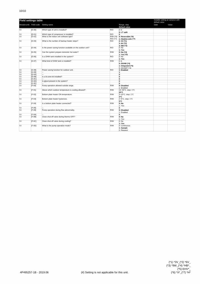
10/10
Breadcrumb Field code Setting name Range, stepDefault value
Date Value
Field settings table Installer setting at variance with default value
9.I [E-00] R/O 0~50: LT split
9.I [E-01] R/O 09.I [E-02] R/W (*6)
R/O (*7)0: Reversible (*6)1: Heating only (*7)
9.I [E-03] R/O 2: 3V (*1)3: 6V (*2)4: 9W (*3)
9.I [E-04] R/O 0: No1: Yes
9.I [E-05] R/W 0: No (*4)1: Yes (*5)
9.I [E-06] R/O 0: No1: Yes
9.I [E-07] R/W 0~60: EKHW (*4)1: Integrated (*5)5: EKHWP (*4)
9.I [E-08] R/O 1: Enabled9.I [E-09] 19.I [E-0A] 09.I [E-0B] 09.I [E-0C] 09.I [E-0D] 09.I [E-0E] 09.I [F-00] R/W 0: Disabled
1: Enabled9.I [F-01] R/W 10~35°C, step: 1°C
20°C9.I [F-02] R/W 3~10°C, step: 1°C
3°C9.I [F-03] R/W 2~5°C, step: 1°C
5°C9.I [F-04] R/W 0: No
1: Yes9.I [F-05] 09.I [F-09] R/W 0: Disabled
1: Enabled9.I [F-0A] 09.I [F-0B] R/W 0: No
1: Yes9.I [F-0C] R/W 0: No
1: Yes9.I [F-0D] R/W 0: Continuous
1: Sample2: Request
Close shut-off valve during cooling?
What is the pump operation mode?
Is a bottom plate heater connected?
--Pump operation during flow abnormality.
--Close shut-off valve during thermo OFF?
Is a bi-zone kit installed?--
Above which outdoor temperature is cooling allowed?
Bottom plate heater ON temperature.
Bottom plate heater hysteresis.
Can the system prepare domestic hot water?
Is a DHW tank installed in the system?
What kind of DHW tank is installed?
Power saving function for outdoor unit.----
What is the indoor unit software type?
What is the number of backup heater steps?
Is the power saving function available on the outdoor unit?
Pump operation allowed outside range.
Is glycol present in the system?--
Which type of unit is installed?
Which type of compressor is installed?
4P495257-1B - 2019.06 (#) Setting is not applicable for this unit.
(*1) *3V_(*2) *6V_(*3) *9W_(*4) *HB*_
(*5) EHV*_(*6) *X*_(*7) *H*


ROTEX Heating Systems GmbHLangwiesenstraße 10D-74363 Güglingenwww.rotex-heating.com
Unsere Partner im AuslandOur partners abroad • Unsere Partner im AuslandNos partenaires à l’étranger • Le nostre sedi all'esteroNeustros representantes en el extranjeroNasi partnerzy za granicą • Naši partneři v zahraničí
http://de.rotex-heating.com > ueber-rotex > international 4P495262-1B 2019.10
© R
OTE
X ∙ S
ubje
ct to
cha
nge
and
corre
ctio
n