rotex rps4 operating and installation instructions · regulation and pump unit for solaris solar...
TRANSCRIPT

For the qualified installer
ROTEX RPS4Operating and installation instructions
Regulation and pump unit for Solaris Solar Systems
Valid for the following components- ROTEX Solaris RPS4 - Solaris R4 Differential temperature control
GBOutput 04/2016
2 FA ROTEX Solaris RPS4 - 04/2016
1 x Guarantee1 Guarantee
1.1 Warranty conditionsThe legal guarantee conditions fundamentally apply. Our war-ranty conditions beyond that can be found online on your sales representative's webpage.
List of contents
FA ROTEX Solaris RPS4 - 04/2016 3
1 Guarantee . . . . . . . . . . . . . . 21.1 Warranty conditions . . . . . . . . . . . . . . . . . . . . . .2
2 Safety . . . . . . . . . . . . . . . . . . . . . . . . . . . . . . . 42.1 Observing instructions . . . . . . . . . . . . . . . . . . . .42.2 Warning signs and explanation of symbols. . . . .42.3 Avoid danger. . . . . . . . . . . . . . . . . . . . . . . . . . . .52.4 Intended use . . . . . . . . . . . . . . . . . . . . . . . . . . . .52.5 Instructions for working safely. . . . . . . . . . . . . . .5
3 Manual operation . . . . . . . . . . . . . . . . . . . . . 63.1 Structure and Components of Solaris system. . .63.2 Info parameters. . . . . . . . . . . . . . . . . . . . . . . . . .73.3 System components . . . . . . . . . . . . . . . . . . . . . .7
3.3.1 Regulation and pump unit RPS4 . . . . . . . . . . . . . . 73.3.2 Optional accessories . . . . . . . . . . . . . . . . . . . . . . . 8
4 Peak output . . . . . . . . . . . . . . . . . . . . . . . . . . 94.1 System concepts. . . . . . . . . . . . . . . . . . . . . . . . .9
4.1.1 Parallel connection . . . . . . . . . . . . . . . . . . . . . . . . 94.1.2 Serial connection. . . . . . . . . . . . . . . . . . . . . . . . . . 9
4.2 Installing the control and pump unit . . . . . . . . .104.2.1 Installation pump unit . . . . . . . . . . . . . . . . . . . . . 104.2.2 Installation of FlowSensor, FlowGuard (optional) 114.2.3 Installing temperature sensor . . . . . . . . . . . . . . . 124.2.4 Preparing and fitting the control system . . . . . . . 134.2.5 Fit the covering hood. . . . . . . . . . . . . . . . . . . . . . 15
5 Start-up and decommissioning . . . . . . . . . 165.1 Start-up . . . . . . . . . . . . . . . . . . . . . . . . . . . . . . .165.2 Control Brief description . . . . . . . . . . . . . . . . . .17
5.2.1 Temporary shutdown. . . . . . . . . . . . . . . . . . . . . . 175.2.2 Final shutdown . . . . . . . . . . . . . . . . . . . . . . . . . . 18
6 FlowSensor . . . . . . . . . . . . . . . . . . . . . . . . . 196.1 Operating and display components . . . . . . . . .196.2 Operating mode of control system . . . . . . . . . .20
6.2.1 Pump operation . . . . . . . . . . . . . . . . . . . . . . . . . . 206.2.2 Booster function for high solar panel
temperatures . . . . . . . . . . . . . . . . . . . . . . . . . . . . 206.2.3 Start optimisation. . . . . . . . . . . . . . . . . . . . . . . . . 206.2.4 Switch-on block functions . . . . . . . . . . . . . . . . . . 206.2.5 Pump kick function . . . . . . . . . . . . . . . . . . . . . . . 216.2.6 Manual operation. . . . . . . . . . . . . . . . . . . . . . . . . 216.2.7 FlowSensor . . . . . . . . . . . . . . . . . . . . . . . . . . . . . 216.2.8 Output calculation, maximum values,
and yield count . . . . . . . . . . . . . . . . . . . . . . . . . . 226.2.9 Speed regulation of the solar operating
pump PS . . . . . . . . . . . . . . . . . . . . . . . . . . . . . . . 226.2.10 Total Reset Function . . . . . . . . . . . . . . . . . . . . . . 236.2.11 Frost protection function . . . . . . . . . . . . . . . . . . . 236.2.12 Leak protection function . . . . . . . . . . . . . . . . . . . 23
6.3 Adjustment and menu guide . . . . . . . . . . . . . . .246.3.1 Fast access . . . . . . . . . . . . . . . . . . . . . . . . . . . . . 256.3.2 Display during operation . . . . . . . . . . . . . . . . . . . 256.3.3 Setup menu . . . . . . . . . . . . . . . . . . . . . . . . . . . . . 256.3.4 Password input . . . . . . . . . . . . . . . . . . . . . . . . . . 276.3.5 Language selection . . . . . . . . . . . . . . . . . . . . . . . 276.3.6 Setting and resetting parameters . . . . . . . . . . . . 276.3.7 Setting the mounting position of the solar panel
temperature sensor . . . . . . . . . . . . . . . . . . . . . . . 276.3.8 Manual setting of the pump speed regulation . . . 286.3.9 Correction values for measuring points. . . . . . . . 28
6.3.10 Cylinder temperature sensor . . . . . . . . . . . . . . . . 286.4 Recommended settings . . . . . . . . . . . . . . . . . . 29
6.4.1 Standard parameter settings, recommended setting ranges . . . . . . . . . . . . . . . . . . . . . . . . . . . 29
6.4.2 Additional settings for your solar system . . . . . . . 306.4.3 Setting recommendation for the post-heating via
external heat sources or by the electrical immersion heater, burner blocking contact . . . . . 31
6.4.4 Tips for optimised user behaviour . . . . . . . . . . . . 316.4.5 Domestic water hygiene . . . . . . . . . . . . . . . . . . . 31
7 Faults and malfunctions. . . . . . . . . . . . . . . 327.1 Display of events . . . . . . . . . . . . . . . . . . . . . . . 327.2 Troubleshooting . . . . . . . . . . . . . . . . . . . . . . . . 33
8 Hydraulic system connection . . . . . . . . . . 358.1 Schematics . . . . . . . . . . . . . . . . . . . . . . . . . . . 358.2 Connection of a pressure solar panel system . 39
9 Technical data . . . . . . . . . . . . . . . . . . . . . . . 409.1 Product Fiche. . . . . . . . . . . . . . . . . . . . . . . . . . 409.2 Regulation and pump unit RPS4 . . . . . . . . . . . 409.3 Sensor characteristics . . . . . . . . . . . . . . . . . . . 409.4 Pump characteristic curve . . . . . . . . . . . . . . . . 41
10 Notes . . . . . . . . . . . . . . . . . . . . . . . . . . . . . . 42
11 List of keywords . . . . . . . . . . . . . . . . . . . . . 43

4 FA ROTEX Solaris RPS4 - 04/2016
2 x Safety2 Safety
2.1 Observing instructionsThese instructions are a >> translation of the original version << in your language.
All activities required for installation, commis-sioning, operation, and adjustment of the heating system are described in this manual. For de-tailed information regarding the connected com-ponents of your heating system, please observe the respective documents.
Work on the ROTEX RPS4 (such as hydraulicand electrical connection and initial start-up)is only to be carried out by persons who areauthorised and who have successfullycompleted qualifying technical or vocationaltraining and who have taken part in advancedtraining sessions recognised by the appro-priate responsible authorities for the specificactivity. This includes, in particular, heatingspecialists who, as a result of their technicaltraining and knowledge, have experience withthe proper and appropriate installation andmaintenance of heating systems and solarsystems.Please read this manual carefully andthoroughly before proceeding with the instal-lation and commissioning or carrying out anoperation on the heating system.Comply strictly with warning instructions!
Relevant documentsDocuments listed below are part of the technical documentation of the ROTEX solar system and therefore must be observed. The documents are included in the scope of supply of the individual components.
– ROTEX high-performance flat solar panelsSolaris V21P, V26P and H26P. Installation instructions for on-roof, in-roof and flat-roof mounting
– ROTEX hot water storage tank (SanicubeSolaris / HybridCube, GCU compact or HPSU compact): Operating and installation instructions
When connecting to an external heat generator or storage tank which is not included in the scope of delivery, the individual associated operating and installation instructions apply.
2.2 Warning signs and explanation of symbols
Meaning of the warningsWarnings in this manual are classified according into their severity and probability of occurrence.
Special warning signsSome types of danger are indicated by special warning signs.
Order numberNotes related to order numbers are identified by the shopping cart symbol .
DANGER!Draws attention to imminent danger.
Disregarding this warning can lead to serious injury or death.
WARNING!Indicates a potentially dangerous situation.
Disregarding this warning may result in serious physical injury or death.
CAUTION!Indicates a situation which may cause possible damage.
Disregarding this warning can lead to damage to property and the environment.
This symbol identifies user tips and par-ticularly useful information, but not warn-ings or hazards.
Electric power
Danger of explosion
Risk of burning or scalding

2 x Safety
FA ROTEX Solaris RPS4 - 04/2016 5
Handling instructionsInstructions on actions are shown as a list.Actions of which the sequential order must bemaintained are numbered.
Results of actions are identified with anarrow.
2.3 Avoid dangerROTEX solar installations are state-of-the-art and are built to meet all recognised technical requirements. However, improper use can lead to serious injuries or death, as well as causing material damage. Install and operate only ROTEX solar systems to avoid danger:– as stipulated and in perfect condition,– with an awareness of the safety and hazards
involved.This assumes knowledge and use of the con-tents of this manual, the relevant accident pre-vention regulations and the recognised safety-related and occupational medical rules.
2.4 Intended useThe ROTEX solar system may only be used for solar-supported heating of hot water systems. The ROTEX solar system must be installed, con-nected and operated only according to the in-structions in this manual.
The regulation and pump unit is not suitable for use in an explosive atmosphere.
Any other use outside the intended use is con-sidered as improper. The operator alone shall bear responsibility for any resulting damage.
Intended use also includes compliance with the maintenance and service conditions. Spare parts must at least satisfy the technical require-ments defined by the manufacturer. This is the case, for example, with original spare parts.
2.5 Instructions for working safely
Working on the roofInstallation work on the roof may only becarried out by authorised and trained persons(heating technicians, roofers, etc.) underobservance of the relevant AccidentPrevention Regulations.Material and tools must be secured againstfalling.Barriers must be erected to prevent personsfrom entering the area below the roof wherethe work is being carried out.
Before working on the heating systemAll work on the heating system (such as instal-lation, connection and commissioning) mayonly be carried out by authorised and trainedheating technicians.Switch off the main switch and secure itagainst unintended switching on whencarrying out any work on the heating system.
Electrical installationElectrical installation must be carried out onlyby qualified electrical experts and incompliance with the valid electro-technicalguidelines as well as the regulations of therelevant energy supply company (EVU).Make up the power supply in accordance withIEC 60335-1, via an isolator with contactseparation in all poles with a contact openingdistance in accordance with the conditions ofthe over-voltage category III for full discon-nection, and a residual current protectionswitch (FCD) having a reactiontime 0.2 secs.Before completing the mains connection,compare the mains voltage, indicated on thetype plate (230 V, 50 Hz) with the supplyvoltage.Before beginning work on live parts,disconnect them from the power supply(switch off main switch, remove fuse) andsecure against unintentional restart.Equipment covers and service panels must bereplaced as soon as the work is completed.
Instructing the user/ownerBefore you hand over the heating system,explain to the user/owner how to operate andcheck the heating system.Make a record of the handover by filling outand signing the installation and instructionforms jointly with the user/owner.

6 FA ROTEX Solaris RPS4 - 04/2016
3 x Manual operation3 Manual operation
3.1 Structure and Components of Solaris system
Fig. 3-1 Standard design of a ROTEX Solaris solar system (ROTEX recommends a double-sided connection)
1 Cold water connection line2 Domestic water (hot) distribution line3 Stainless steel corrugated heat exchanger for domestic water
(hot)4a Stainless steel corrugated heat exchanger for storage tank charg-
ing4a Stainless steel corrugated heat exchanger for storage tank charg-
ing and heating support5 Submersion sleeve for storage, return temperature sensors6 Fill level display7 Filling and draining hose (KFE BA, 16 52 15 accessory)8 Solaris R4 regulator9 Solar return line (at the bottom on the solar panel)10 Solar panel array11 Solar flow line (at the top on the solar panel)12 Thermal mixing valve (scalding protection, provided by customer)13 Convection brake (accessory)14 Solar flow layering pipe15 Corrugated stainless steel heat exchanger for heating support16 Thermal insulation sleeve for corrugated stainless steel heat ex-
changer for heating support17 Solar return connection18 Safety overflow connection
A Zone with water for domestic useB Solar zoneFLS Solaris FlowSensor (flow measuring) PS Solaris operating pumpRPS4
Regulation and pump unittDHW Storage temperature sensorTK Solaris Solar panel temperature sensorTR Solaris Return flow temperature sensorTS Solaris Storage tank temperature sensorTV Solaris Inflow temperature sensor
GCU compactGas Combi Unit
HPSU compactSolar tank with integrated interior heat pump unit
SCS/HYCEnergy store Sanicube Solaris / HybridCube
Tab. 3-1 Legend for fig. 3-1

3 x Manual operation
FA ROTEX Solaris RPS4 - 04/2016 7
3.2 Info parametersThe ROTEX solar system is a thermal solar system for supplying hot water for consumption and solar support.
Password protectionThe Solaris V21P, V26P and H26P high-performance solar panels efficiently convert the sun’s radiation into heat. The heat transport medium is normal tap water.
As soon as the solar collectors have reached a useful temper-ature level, the water of the heating jacket in the storage cylinder (which is not under pressure) is pumped directly through the collectors. With insufficient collector temperature, the circulation pump is switched off and the system is drained automatically. This operating mode has several advantages:– High operational reliability, as there are no components that
could be damaged or fail (such as expansion vessel, safetyvalve, venting valves, etc.).
– Excellent heat transfer and heat storage capacity (systemworks without antifreeze agents).
– Minimum maintenance requirements.– Frost proof.– Without separate solar heat exchanger.– No stagnation problems.
Modular designThe system consists of several preassembled modules. Plug-in technology and a high degree of pre-assembly ensure fast and simple system installation.
Storage tankThe following storage tanks can be used for the ROTEX solar system:– ROTEX Sanicube Solaris (SCS): Thermally insulated, de-
pressurised plastic storage tank (with connection facility for aROTEX air-water heat pump).
– ROTEX HybridCube (HYC): Thermally insulated, de-pressur-ised plastic storage tank (with connection facility for a ROTEX air-water heat pump).
– ROTEX GCU compact: Solar storage tank with integrated gas condensing boiler.
– ROTEX HPSU compact: Solar storage tank with integratedinternal unit of an air-water heat pump.
Electronic controlThe fully electronic ROTEX Solaris R4 regulator ensures op-timum utilisation of the solar heat (hot water generation, heating support) and that all safety-relevant aspects are complied with. All parameters needed for trouble-free operation have been preset at factory.
3.3 System components
3.3.1 Regulation and pump unit RPS416 41 26
The ROTEX regulation and pump unit RPS4 can only be installed and operated in the depressurised ROTEX Solaris System (DrainBack) using the provided installa-tion material.
The prerequisite for problem-free operation in the DrainBack system, is that the connection lines are routed with a constant gradient (at least 2 %), and that the bottom edges on the solar panels with double-sided connections are mounted with a con-stant gradient to the return connection, or, with same side con-nection, are mounted horizontally.
Construction, operating principle, commissioning, and operation of other Solaris components are not described in this manual. Detailed information about the components can be seen in the operating and installa-
tion instructions of the individual units.
The handling instructions and descriptions in this manual are valid for all ROTEX storage tanks to be used in conjunction with this solar system, even if only one type (z. B. SCS) is used for illustrative purposes. Where other cylinders deviate, this will be pointed out separately.
Consists of:1 Cover2 Connecting pipework to the solar operating pump3 ROTEX Solaris R4 regulator with storage tank temperature sen-
sor, return flow temperature sensor, connecting cable solar panel temperature sensor, FlowSensor, connection cable 230 V mains connection (3 m)
4 Accessories bag (angle, 4 countersunk head screws, 4 self-tap-ping screws, sensor plugs, plastic plugs)
5 Mounting material (retaining bracket for pump mounting, holding bar and fixing bracket for controller)
6 Solaris DocumentationFig. 3-2 Regulation and pump unit (RPS4)

8 FA ROTEX Solaris RPS4 - 04/2016
3 x Manual operation3.3.2 Optional accessories
KFE Filling connectionFor convenient filling and draining of the ROTEX hot water storage tank, you can connect the KFE filling connection (KFE BA 16 52 15).
FlowGuardFor setting and display of the flow rate of 2-6 l/min, you can use the setting valve (FlowGuard FLG 16 41 02).
Solar storage tank extension kitIf the heat output of a single ROTEX hot water storage tank is not adequate, you can interconnect several Sanicube / HybridCube as modules.
The following components are offered:– Solar storage tank extension kit CON SX ( 16 01 20)– Solar storage tank kit 2 CON SXE ( 16 01 21)– FlowGuard FLG ( 16 41 02)The installation and operation of this accessory component is de-scribed in detail in the individual operating and installation in-structions provided.
Additional pump kit for tall buildingsIf the top edge of the solar panel is more than 12 m above the erection surface of the solar storage tank, the system can be op-erated up to a maximum total height of the system of 18 m if the additional pump kit ZP-RPS4 ( 16 42 43) is installed.

4 x Peak output
FA ROTEX Solaris RPS4 - 04/2016 9
4 Peak output
4.1 System conceptsROTEX solar systems are usually built according to one of the following system concepts. Information concerning hydraulic system incorporation with example schematics can be seen in section 8 "Hydraulic system connection".
4.1.1 Parallel connection
4.1.2 Serial connectionAs an alternative to the parallel mode described in this manual, and if necessary, a maximum of 3 solar panels can be mounted one above the other. Solar panels or solar panel fields mounted one above the other must be connected in series (fig. 4-3).
Fig. 4-1 Solar panel field with a connection at each end (recommended)
Fig. 4-2 Solar panel field with both connections at one end (max. 3 solar panels)
TK
Fig. 4-3 Alternative solar panel arrangement
1 Collector connector2 Mounting rail3 Solar panel securing hook4 Solar panel5 Return panel connection6 Flow panel connection7 Collector sealing cap8 Roof penetration boxes for inflow/return flow9 Solar return line10 Solar flow line11 Series panel connector12 Solar panel array (2x2 panels)Tab. 4-1 Legend for fig. 4-3
10 FA ROTEX Solaris RPS4 - 04/2016
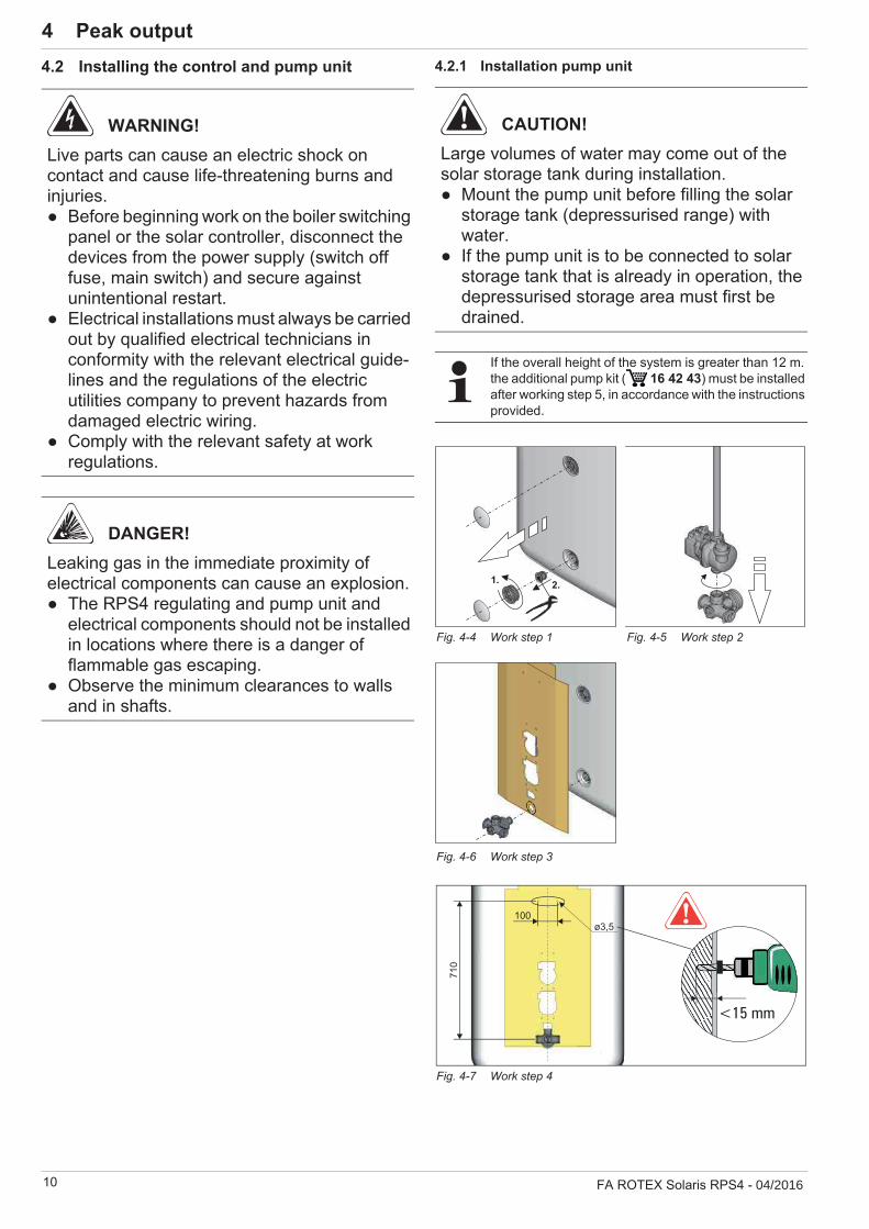
4 x Peak output4.2 Installing the control and pump unit 4.2.1 Installation pump unit
WARNING!Live parts can cause an electric shock on contact and cause life-threatening burns and injuries.
Before beginning work on the boiler switchingpanel or the solar controller, disconnect thedevices from the power supply (switch offfuse, main switch) and secure againstunintentional restart.Electrical installations must always be carriedout by qualified electrical technicians inconformity with the relevant electrical guide-lines and the regulations of the electricutilities company to prevent hazards fromdamaged electric wiring.Comply with the relevant safety at workregulations.
DANGER!Leaking gas in the immediate proximity of electrical components can cause an explosion.
The RPS4 regulating and pump unit andelectrical components should not be installedin locations where there is a danger offlammable gas escaping.Observe the minimum clearances to wallsand in shafts.
CAUTION!Large volumes of water may come out of the solar storage tank during installation.
Mount the pump unit before filling the solarstorage tank (depressurised range) withwater.If the pump unit is to be connected to solarstorage tank that is already in operation, thedepressurised storage area must first bedrained.
If the overall height of the system is greater than 12 m. the additional pump kit ( 16 42 43) must be installed after working step 5, in accordance with the instructions provided.
Fig. 4-4 Work step 1 Fig. 4-5 Work step 2
Fig. 4-6 Work step 3
Fig. 4-7 Work step 4
100
710
ø3,5
<15 mm

4 x Peak output
FA ROTEX Solaris RPS4 - 04/2016 11
4.2.2 Installation of FlowSensor, FlowGuard (optional)
FlowSensorThe FlowSensor FLS 20 (fig. 4-18) is a measuring device that simultaneously determines the flow rate in the solar panel and the flow temperature. The measuring ranges are 0...20 l/min (flow quantity) and 0...120°C (inflow temperature). The measured values are displayed on the Solaris R4 regulator. By controlling the speed of the solar operating pump PS, the Solaris R4 regulator automatically adjusts the optimum flow quantity.
1. Insert the seal (b) in the solar flow connection (a) on the DHWcylinder.
2. Screw the FlowSensor (c) on to the solar flow connection (a)on the DHW cylinder.
3. Fit the seal (e) and insert the push-in fitting (f) in the inlet ofthe FlowSensors (c).
4. Cut the flow pipe (g) (Ø 15 mm) to the required length andinsert it in the push-in fitting (f).
5. Route the FlowSensor cable between the FlowSensor (c) and the Solaris R4 regulator.
6. Plug the FlowSensor cable into the FlowSensor (c) and ontothe edge of the Solaris R4 regulator circuit board at positionFLS (4-pin, see fig. 4-24).
Fig. 4-8 Work step 5 Fig. 4-9 Work step 6
Fig. 4-10 Work step 7 Fig. 4-11 Work step 8
Fig. 4-12 Work step 9 Fig. 4-13 Work step 10
Fig. 4-14 Work step 11 Fig. 4-15 Work step 12
Fig. 4-16 Work step 13
CAUTION!In the case of longer pipe runs with only a minimum gradient, it is possible for water pockets to develop due to thermal expansion of the plastic pipes between the mounting points with siphon action:
Use support troughs (TS 16 42 45).Always make sure that pipe runs have acontinuous gradient of at least 2 %.
Note the direction of flow when installing the FlowSen-sor.
Fig. 4-17 Installation FlowSensor FLS
12 FA ROTEX Solaris RPS4 - 04/2016
4 x Peak output
FlowGuardThe FlowGuard FLG (fig. 4-20, 16 41 02) is available as an accessory. It is a regulating valve with integrated flow indicator which can be used to set the flow rate through the solar panel array. The display range is 2… 16 l/min.
1. Insert the seal in the flow connection (see fig. 4-19).
2. Mount the FlowGuard, and screw it tight.
3. Fit the seal and insert the push-in fitting in the inlet of theFlowGuard.
4. Insert the prepared flow pipe into push-in fitting in theFlowGuard.
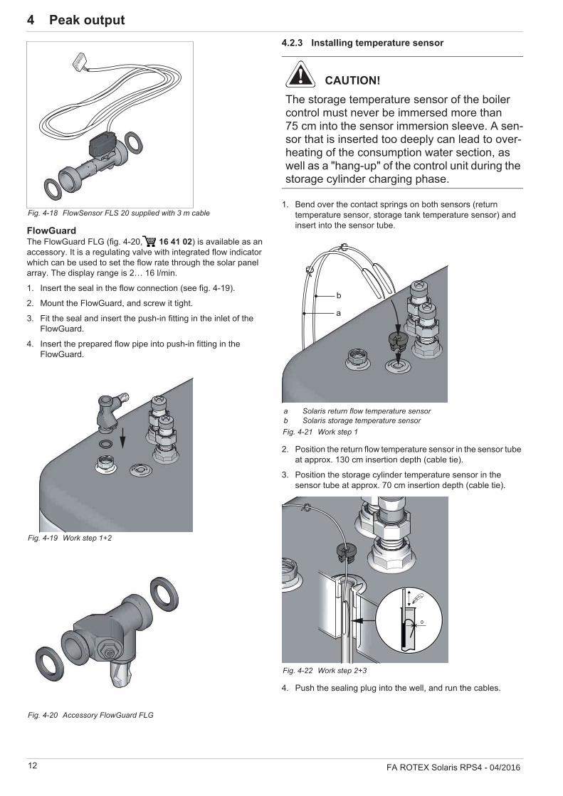
4.2.3 Installing temperature sensor
1. Bend over the contact springs on both sensors (returntemperature sensor, storage tank temperature sensor) andinsert into the sensor tube.
2. Position the return flow temperature sensor in the sensor tube at approx. 130 cm insertion depth (cable tie).
3. Position the storage cylinder temperature sensor in thesensor tube at approx. 70 cm insertion depth (cable tie).
4. Push the sealing plug into the well, and run the cables.
Fig. 4-18 FlowSensor FLS 20 supplied with 3 m cable
Fig. 4-19 Work step 1+2
Fig. 4-20 Accessory FlowGuard FLG
CAUTION!The storage temperature sensor of the boiler control must never be immersed more than 75 cm into the sensor immersion sleeve. A sen-sor that is inserted too deeply can lead to over-heating of the consumption water section, as well as a "hang-up" of the control unit during the storage cylinder charging phase.
a Solaris return flow temperature sensorb Solaris storage temperature sensorFig. 4-21 Work step 1
Fig. 4-22 Work step 2+3
4 x Peak output
FA ROTEX Solaris RPS4 - 04/2016 13
4.2.4 Preparing and fitting the control system
Requirements– For electrical connections and consumable electrical materi-
als (cable, insulation, etc.), follow all valid country-specific guidelines.
– For every fixed mains connection, use a separateEN 60335-1 disconnector for all-pole disconnection from the power mains and a GFCI circuit breaker with a reactiontime 0.2 s.
Permissible cable types at the terminal strip:– Single core 2.5 mm2
– Multi-core 2.5 mm2
– Multi-core with wire end sleeves with insulatingcollar 1.5 mm2
– Multi-core with wire end sleeves without insulatingcollar 2.5 mm2
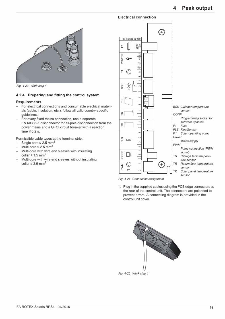
Electrical connection
1. Plug in the supplied cables using the PCB edge connectors at the rear of the control unit. The connectors are polarised toprevent errors. A connecting diagram is provided in thecontrol unit cover.
Fig. 4-23 Work step 4
BSK Cylinder temperature sensor
CONFProgramming socket for software updates
F1 FuseFLS FlowSensorP1 Solar operating pumpPower
Mains supplyPWM
Pump connection (PWM signal)
TS Storage tank tempera-ture sensor
TR Return flow temperature sensor
TK Solar panel temperature sensor
Fig. 4-24 Connection assignment
Fig. 4-25 Work step 1

14 FA ROTEX Solaris RPS4 - 04/2016
4 x Peak output2. To ensure reliable tension relief, all cables should be run
through the respective labyrinths.
4. Insert the plug at the edge of the board on the controller, atposition TK (2-pin, see fig. 4-24).
5. Insert the control unit into its fixing bracket from above.– Make sure that the cable loops (as shown in fig. 4-28 and
fig. 4-29) point downwards.
6. Cabling of the solar operating pump PS:– Connect the pump cable to the solar operating pump PS.
7. Run the control cables along the return pipe and fix them withcable ties.
Fig. 4-26 Work step 2
3. Connect the collectortemperature sensor cable(integrated into theconnecting cable) to theplug.
Fig. 4-27 Work step 3
Fig. 4-28 Basic wiring: FlowSensor for storage cylinder, return flow, and collector, pump supply, mains supply
Fig. 4-29 Work step 5
Fig. 4-30 Work step 6
Fig. 4-31 Work step 7

4 x Peak output
FA ROTEX Solaris RPS4 - 04/2016 15
4.2.5 Fit the covering hood1. Fit the cover and align it. Make sure that the cover is pushed
under the control unit housing so that there is an evenlyspaced joint all around the control unit.
2. Fix the cover to the control unit on both sides withcountersunk screws.
3. Fasten the cover to the cylinder connecting bracketunderneath. To do this, carefully screw in the self-tappingfixing screw (pre-fitted on the cover) through the recess in thelower part of the front of the housing and then fit the covercap.
Fig. 4-32 Work step 1
Fig. 4-33 Work step 2
Fig. 4-34 Work step 3
Fig. 4-35 Completely installed RPS4
16 FA ROTEX Solaris RPS4 - 04/2016
5 x Start-up and decommissioning5 Start-up and decommissioning
5.1 Start-up
All the following work must be carried out in the specified se-quence.
1. Filling the storage cylinder:Filling the heat exchanger for domestic water.
Fill the buffer storage volume via the filling and draininghose (KFE BA, 16 52 15) on the regulation and pump unit RPS4 until water comes out of the safety overflow.Close the filling and drain valve (KFE BA, 16 52 15).
2. Switch on the Solaris R4 regulator.The initialisation phase begins.
3. When the initialisation phase is finished (temperaturedisplay), fill and vent the solar system by simultaneouslypressing both arrow keys (starting manual mode).
The solar operating pump PS now runs at full power andthe solar system is exposed to the maximum possible operating pressure. The solar system fills, the air escapes through the flow line into the air compartment of the stor-age tank.
4. Check the entire system for leaky joints (in the building andon the roof). Seal any leaks that occur in a professionalmanner.
5. Switch off the Solaris R4 regulator.
6. Check the filling level in the hot water storage tank.
7. Adjusting the filling time:Switch the Solaris R4 regulator on again (initialisationphase starts).When the initialising phase is finished (temperaturedisplay), you can start the manual operating mode bysimultaneously pressing both arrow keys.Measure the time it takes to fill the solar systemcompletely. The system is fully filled when you can nolonger hear any air noises and a steady value for the flowrate is displayed (activate the measuring point [Flow rate]using the arrow keys).Set the measured time plus 20 seconds in theparameter [time P2] (see section 6.3.6).
8. Switch the Solaris R4 regulator to the automatic mode bypressing the two arrow keys simultaneously or by switchingoff and on again.
The solar system is now ready for operation.
9. Only when connecting a RPS4 regulating and pump unit toseveral solar storage tanks:– The entire flow rate, measured with the FlowSensor in the
solar flow line must be distributed evenly to all the con-nected solar storage tanks. We recommend using aFlowGuard (FLG) at each storage tank for regulation pur-poses.
10. Instruct the user, fill out the acceptance report, and send it tothe address indicated on the rear cover of this manual.
WARNING!The solar system cannot be started until all hydraulic and electrical connections have been completed.
Incorrect commissioning will impair the system's function, and can lead to damage to the entire installation. Installation and start-up must therefore must conducted by ROTEX-au-thorised and trained heating experts.
The protective conductor resistance and correct wiring must be checked before start-up.
CAUTION!Commissioning in frosty conditions can result in damage to the entire heating system.
Commissioning with outside temperaturesbelow 0°C should only be undertaken if awater temperature of at least 5°C in the solarcircuit can be guaranteed (e.g. by previousheating of the DHW cylinder).
ROTEX recommends that you avoid operating the system in extremely frosty conditions.
UK only! CAUTION!If filling or topping up the storage tank is done by means of the boiler filling and drain valve, a temporary filling loop must be used with the appropriate backflow prevention device in accordance with clause G24.2, Guidance to the Water Supply (Water Fittings) Regulations 1999.
The domestic water quality must comply with the EU Guideline 98/83 EC and the regionaly-applica-ble regulations.
Within a few minutes after switching off and emptying of the solar system, the fill level indicator in the hot water storage tank once again reach almost to the fill level.
– The reason for a slightly lower fill level is the remaining of asmall volume of water in the lower collection pipes in the pan-els. If the solar panels are correctly aligned, this volume ofwater is not dangerous for the panel, even under the effectsof frost, since there is adequate space for expansion.
– If the fill level remains considerably below the fill level, thiscan be an indication of undiscovered leaks or faulty line rout-ing (water pockets). In this case the installation must bechecked very closely once more.
The correct flow rate in the solar circuit is set automati-cally by regulating the speed of the solar operation pump PS.

5 x Start-up and decommissioning
FA ROTEX Solaris RPS4 - 04/2016 17
5.2 Control Brief description
5.2.1 Temporary shutdown
By turning off at the main switch of the Solaris R4 regulator or by removing the plug from the mains, you can shut down the ROTEX solar system temporarily.
If there is a danger of frost:– the ROTEX solar system must be taken into operation
againor
– suitable antifreeze measures must be applied to the con-nected heating system and hot water storage tank (e.g. draining).
Draining the storage tankSeparate all power circuits of the solar and heating systemfrom the power supply and secure against inadvertent switching on again.Only GCU compact: Close gas stopcock.Connect the drain hose to the (KFE BA, 16 52 15) (fig. 5-1, item A) filling and draining hose and route to a wastewater drainage point which is at least at ground level.
Tab. 5-1 Legend from fig. 5-1 to fig. 5-3
Adjust the valve insert on the connecting angle so that thepath to the blind plug is blocked off (fig. 5-2).Remove the blanking plug from the connecting elbow(fig. 5-2) and place a suitable collection trough beneath theunit.
CAUTION!A heating system which is shut down can freeze in the event of frost and may suffer damage.
Drain the heating system that is shut down ifthere is danger of frost.
CAUTION!CAUTION! Pumps that are switched off for a long time can seize.With temporarily shut-down solar systems, the protection function from seized pumps (pump kick function) is also deactivated.
Check for correct pump function whenstarting up again. Seized pumps can usually be freed up manually.
If the danger of freezing will only last for a few days, the very good heat insulation of the ROTEX means that it need not be drained, as long as the storage tank tem-perature is observed regularly and not permitted to fall
below +3°C. This does not, however, provide any protection against frost for the connected heat distribution system!
If no KFE filling connection is available, the con-nection piece (fig. 5-1, item C) can be removed from the safety overflow (fig. 5-1, item B) and used as an alternative.
Once the drainage process is complete, this must be re-placed before the heating system can be started again.
Fig. 5-1 Connecting the drain-age hose
Optional: Removing the connec-tion piece from the safety overflow
A KFE filling connection (ac-cessory KFE BA,
16 52 15)B Safety overflowC Hose connection piece for
safety overflow
E Threaded pieceF Blind plugG Connecting angleX Valve insert
Fig. 5-2 Shutting off the valve insert and removing the blanking plug from the connecting angle

18 FA ROTEX Solaris RPS4 - 04/2016
5 x Start-up and decommissioning
Open the KFE hose on the KFE filling connection(KFE BA, 16 52 15).Adjust the valve insert on the connecting angle so that theflow to the drain hose is opened (also refer to fig. 5-2) anddrain the water content of the storage tank.
5.2.2 Final shutdownTake the ROTEX solar system out of service(see section 5.2.1 "Temporary shutdown").Disconnect the RPS4 control and pump unit from all electrical and water connections.Dismantle the RPS4 control and pump unit in accordancewith the assembly instructions (section 4 "Peak output") inreverse order.Dispose of the RPS4 control and pump unit correctly.
Recommendations for disposal
Insert the KFE fillingconnection (KFE BA,
16 52 15) into the connecting angle andsecure using a retainingclip (fig. 5-3).
Fig. 5-3 Assembling the KFE fill-ing connection in the connecting angle
Thanks to the environmentally friendly design of the solar system, ROTEX has complied with requirements for environmentally sound disposal. During the disposal process, the only waste created is that which can be
used for material or thermal recycling.The materials used that are suitable for recycling can be sorted into individual types.
The designation of the product means that electrical and electronic products may not be disposed of to-gether with unsorted domestic waste.
Proper disposal in compliance with the respective na-tional regulations of the country of use is the responsi-bility of the user/owner.
Disassembly of the system, handling of coolant, oil andother parts may only be carried out by a qualified fitter.Disposal may only be carried out by an organization thatspecialises in reuse, recycling and recovery.
Further information is available from the installation company or the responsible local authorities.

6 x FlowSensor
FA ROTEX Solaris RPS4 - 04/2016 19
6 FlowSensor
6.1 Operating and display components
1 Main switch with indicator light2 Display of temperature and parameter dis-
play (energy saving function: Display illumi-nation is switched off 10 minutes after the last key actuation)
3 Light for collector temperature display4 Light for solar flow temperature and flow
measurement (FLS)5 Light for storage cylinder temperature dis-
play6 Light for solar return flow temperature dis-
play
7 Operating status light for speed-controlled solar operating pump PS (lights up when pump running - flickers if the pump is run-ning in a restricted condition)
8 Up arrow for moving the temperature or pa-rameter display up by one setting/increas-ing parameter settings
9 Down arrow for moving the temperature or parameter display down by one setting/de-creasing parameter settings
10 Information key for accessing the informa-tion level (displays measured values, max-imum values and calculated values) and OK key for confirming and storing settings in the setting menu
11 Controller housing12 Locking screws for device housing (back)13 Type plate
Unit may only be opened by an authorised technician. Disconnect from mains supply before opening the housing.
Fig. 6-1 Operating and display elements
12
007.16 107 49_00
SOLARISRegelungs- und Pumpeneinheit
Typ: RPS 4
230 V / 50 Hz
IPx1
max. 260 W
12 m
18 m
Nennspannung:
Schutzart:
el. Leistungsaufnahme:
max. Pumpen-Förderhöhe:
Her
stel
l-Nr.:
mod
el: 1
6412
6se
rial:
090
0010
1
6
7
5
13
43
2
1089
11

20 FA ROTEX Solaris RPS4 - 04/2016
6 x FlowSensor6.2 Operating mode of control system
6.2.1 Pump operationThe solar system is operated fully-automatically all year round without the need for manual intervention. The speed-regulated pump operation is controlled by the Solaris R4 regulator. The op-erating and display elements are shown in fig. 6-1.
Criterion for actuation:– Pump operation depends on the continuously measured tem-
perature difference between the solar panel (TK) and thereturn flow temperature (TR) and a comparison with the setvalue of the parameter [Delta T on].The solar operating pump PS switches on, if the temperaturedifference (= TK – TR) exceeds rhe value set in the parameter [Delta T on] (e.g. return flow temperature = 40°C and[Delta T on] = 15 K; solar panel temperature > 55°C).
Criteria for switching off:– The solar operating pump PS switches off if the temperature
difference falls below the value set on the parameter[Delta T off].1. Possibility: Normal switch-off if the "filling time" (Parame-ter [time P2]) has expired and the temperature difference between the flow and return temperatures has reached the switch-off condition (TV – TR < [Delta T off]).2. Possibility: Rapid switch-off if the solar panel cools off tooquickly within the "filling time" (Parameter [time P2]) (TK – TR < [Delta T off]).
– Achieving the maximum storage tank temperature set viaparameter [TS max] (TS light flashes). In this case, restartingthe solar operating pump PS is only possible if the storagetank temperature has fallen by more than 2 K.
– Achieving the maximum permissible panel temperature setvia the parameter [TK permitted] (TK light flashes). In thiscase, restarting the solar operating pump PS is only possibleif the solar panel temperature has fallen below the parametervalue [TK permitted] by more than 2 K.
– Faulty FlowSensor.
6.2.2 Booster function for high solar panel temperatures
Above a solar panel temperature of [TK max], the output of the solar operating pump PS is operated at max. output.
This increases the system pressure as well as the flow quantity, which enables more heat to be stored within a shorter time.
The booster temperature can be changed by a heating expert with the parameter [TK max]. This increase in output is switched off again automatically if the booster temperature falls by 5 K.
6.2.3 Start optimisationStart optimisation prevents too frequent cycling and reduces the power consumption. This is a self-learning function. Start optimi-sation is activated in the factory.
6.2.4 Switch-on block functionsThe switch-on block functions prevent:– switching on again if, because of reaching the set maximum
storage tank temperature [TS max] the solar system hasbeen automatically switched off (TS light flashes).
– pump operation with activated "intensified frost protectionfunction" (star symbol flashes in the display - seesection 6.2.11).
– pump operation, if the solar panel temperature exceeds theadjustable value set by the heating expert by parameter[TK permitted] (TK light flashes).
After switching off the solar operating pump PS as a result of the maximum storage tank temperature, continuing impingement of the sun's rays on the solar panel can cause temperatures of over 100°C. If the storage tank temperature falls below the release temperature ([TS max] – 2 K), (e.g. by the removal of hot water), the solar operating pump PS is only switched on again if the tem-perature at the solar panel falls below the value set with the pa-rameter [TK permitted] for the restart protection temperature by 2 K.
The function blocking time ensures that the solar operating pump PS is only released again, after the occurrence of a switch-off condition, after expiry of the blocking time set in the parameter [time SP] (0 – 600 secs.).
This means:– the cycling of the solar system can be minimised.– the solar panel can achieve a higher temperature.– when filling the solar system, the flow temperature does not
fall below the switch-off condition and the system regulatesitself more quickly.
Due to continual improvements for the optimum use of the system, the Solaris R4 has been equipped with an update function. Consequently some of the functions described in this chapter are only applicable to certain
software versions. These functions are separately identified by symbols.
Software updates to the Solaris R4 regulator must only be done by the ROTEX service technician.
The power switch completely disconnects the Solaris R4 regulator from the mains voltage. Switching of the mains switch takes more effort in pushing the but-ton than is required for actuating the operating buttons.
If there is active frost protection (TK<0°C within the last 24 h) there will be no rapid switch-off. The solar operat-ing pump PS is operated for an extended period, so that the connecting lines are heated up to such a tempera-
ture that does not permit the formation of ice plugs.
In this case, however, a considerably higher solar panel temper-ature must be achieved before the solar operating pump PS switches on.
If the solar operating pump PS is switched on at solar panel temperatures over 100°C (TK perm > 100°C), the return water vapourises as soon as it reaches the solar panel. Similarly, a slightly increased consumption of
cylinder water due to escaping steam is a normal operating con-dition.
The water vapour escapes in a depressurised manner into the soalr storage tank in a correctly installed solar sysyem, where it condenses again to a large extent. A slight increase in the con-sumption of buffer water, caused by the escaping unpressurized water vapour, is a normal operating condition.

6 x FlowSensor
FA ROTEX Solaris RPS4 - 04/2016 21
6.2.5 Pump kick functionDuring extended shut-down periods, the solar operating pump PS is activated for a few seconds every 24 hours.
This prevent s the solar operating pump from seizing up.
6.2.6 Manual operationExclusively for commissioning and test purposes, the system can be switched on manually for the time period saved in the pa-rameter [H/A].All the regulation functions are switched off and the solar oper-ating pump PS runs continuously, independent of the system tem-peratures, at the set output stage.
Pressing (>1 s) both arrow keys simultaneously activates ordeactivates manual operation.
6.2.7 FlowSensorThe FlowSensor (FLS) serves to measure the flow rate "V" and the feed temperature "TV".With the sensor connected and working:– the measurement values "V" and "TV" are displayed.– the controller operates after the filling process with the real
spread TV - TR.
If the system has detected the FlowSensor once, the display shows an error message if a sensor is faulty or is disconnected (see section 7.1 "Display of events"). The system then works in the emergency mode without the FlowSensor.
If the controller detects, after a new installation or a technician reset, a FlowSensor, the value "20" is set automatically in the parameter [FLS active].
The correct parameter value for the FlowSensor fitted to the system must always be checked and adjusted if necessary (see tab. 6-1). By entering the parameter value "0" you can deactivate the FlowSensor.
No error message is displayed if the FlowSensor is disabled by the heating technician. The controller now works without the measurement for the flow. The feed temperature "TV" is set to be equal to the solar panel temperature "TK".
CAUTION!Uncontrolled manual operation can lead to heat loss, excessively high storage tank tempera-tures and, under certain cold situations, even to frost damage.
The manual mode cannot be activated with active "en-hanced frost protection function" (star symbol in display flashing - see Section 6.2.10).
22 FA ROTEX Solaris RPS4 - 04/2016
6 x FlowSensor
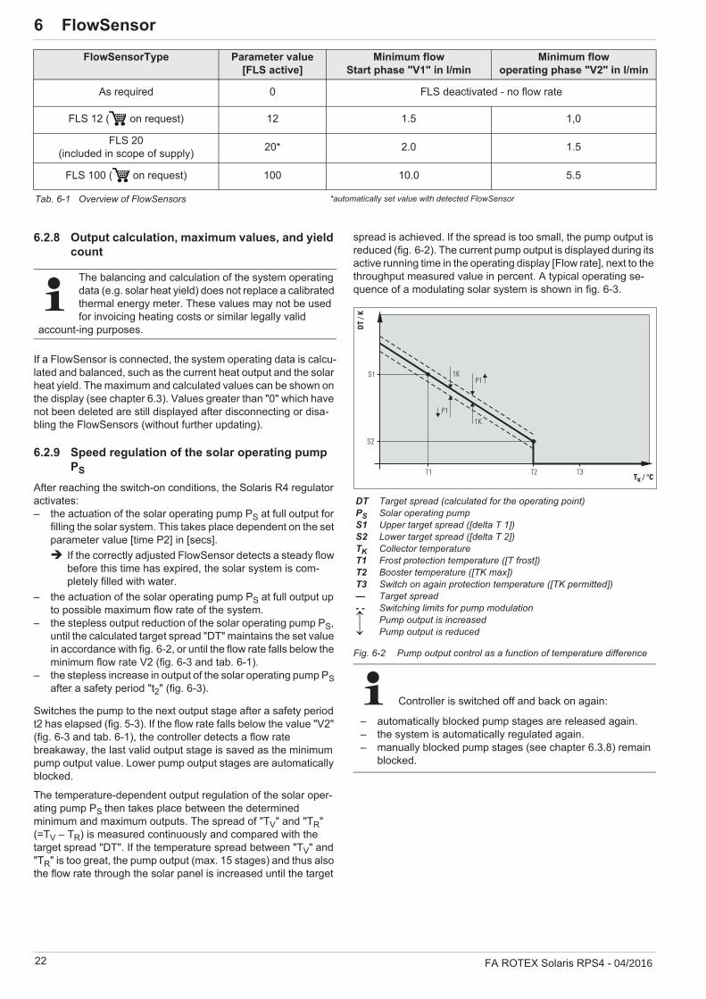
6.2.8 Output calculation, maximum values, and yield count
If a FlowSensor is connected, the system operating data is calcu-lated and balanced, such as the current heat output and the solar heat yield. The maximum and calculated values can be shown on the display (see chapter 6.3). Values greater than "0" which have not been deleted are still displayed after disconnecting or disa-bling the FlowSensors (without further updating).
6.2.9 Speed regulation of the solar operating pump PS
After reaching the switch-on conditions, the Solaris R4 regulator activates:– the actuation of the solar operating pump PS at full output for
filling the solar system. This takes place dependent on the set parameter value [time P2] in [secs].
If the correctly adjusted FlowSensor detects a steady flow before this time has expired, the solar system is com-pletely filled with water.
– the actuation of the solar operating pump PS at full output upto possible maximum flow rate of the system.
– the stepless output reduction of the solar operating pump PS,until the calculated target spread "DT" maintains the set value in accordance with fig. 6-2, or until the flow rate falls below the minimum flow rate V2 (fig. 6-3 and tab. 6-1).
– the stepless increase in output of the solar operating pump PSafter a safety period "t2" (fig. 6-3).
Switches the pump to the next output stage after a safety period t2 has elapsed (fig. 5-3). If the flow rate falls below the value "V2" (fig. 6-3 and tab. 6-1), the controller detects a flow rate breakaway, the last valid output stage is saved as the minimum pump output value. Lower pump output stages are automatically blocked.
The temperature-dependent output regulation of the solar oper-ating pump PS then takes place between the determined minimum and maximum outputs. The spread of "TV" and "TR" (=TV – TR) is measured continuously and compared with the target spread "DT". If the temperature spread between "TV" and "TR" is too great, the pump output (max. 15 stages) and thus also the flow rate through the solar panel is increased until the target
spread is achieved. If the spread is too small, the pump output is reduced (fig. 6-2). The current pump output is displayed during its active running time in the operating display [Flow rate], next to the throughput measured value in percent. A typical operating se-quence of a modulating solar system is shown in fig. 6-3.
Fig. 6-2 Pump output control as a function of temperature difference
FlowSensorType Parameter value[FLS active]
Minimum flow Start phase "V1" in l/min
Minimum flow operating phase "V2" in l/min
As required 0 FLS deactivated - no flow rate
FLS 12 ( on request) 12 1.5 1,0
FLS 20 (included in scope of supply) 20* 2.0 1.5
FLS 100 ( on request) 100 10.0 5.5
Tab. 6-1 Overview of FlowSensors *automatically set value with detected FlowSensor
The balancing and calculation of the system operating data (e.g. solar heat yield) does not replace a calibrated thermal energy meter. These values may not be used for invoicing heating costs or similar legally valid
account-ing purposes.
DT Target spread (calculated for the operating point)PS Solar operating pumpS1 Upper target spread ([delta T 1])S2 Lower target spread ([delta T 2])TK Collector temperatureT1 Frost protection temperature ([T frost])T2 Booster temperature ([TK max])T3 Switch on again protection temperature ([TK permitted])— Target spread- - Switching limits for pump modulation
Pump output is increasedPump output is reduced
Controller is switched off and back on again:
– automatically blocked pump stages are released again.– the system is automatically regulated again.– manually blocked pump stages (see chapter 6.3.8) remain
blocked.

6 x FlowSensor
FA ROTEX Solaris RPS4 - 04/2016 23
Fig. 6-3 Example for modulation operation with flow-caused block of low pump stages on systems with FlowSensor
6.2.10 Total Reset Function
The device reacts to a total reset with a new start (self-test), all parameters are reset to the factory settings and then all the blocked pump output stages are released. The reset takes place:
Via menu path: Activation by heating expert in the settingmenu [System].By quick access: Simultaneous pushing of the OK and arrowkeys.
6.2.11 Frost protection functionAs soon as the solar panel temperature "TK" falls below [T frost] (factory determined frost protection temperature), the frost pro-tection function is activated. It remains activated for 24 h after the limit temperature has been exceeded.
While frost protection is active a star icon is shown in the standard temperature display.
The solar system only starts up with active frost protection if the switch-on condition is fulfilled and the solar panel temperature "TK" exceeds the value "TK save" (factory setting TK save 70°C). The solar operating pump PS, after switching on, runs at least for the time defined in the parameter time P2, even if the switch-off temperature condition is reached before that.
If necessary, (e.g. for long connecting lines outdoors), this minimum start run time can be extended by the heating expert by an adjustable time ([time frost]). This prevents the build-up of ice in the connecting pipe.
The status of the frost protection function [FR active] shows whether the function is activated or deactivated (fig. 6-7). The heating engineer can switch the function on or off manually.
The position of the solar panel temperature sensor can be adjusted in the parameter [TKpos].
For optimising the frost protection, the solar panels must be in-stalled with the sensor position "Bottom".
The parameter [TKpos] must be set to the actual mounting po-sition of the solar panel temperature sensor (see section 6.3.7).
Enhanced frost protection functionAs soon as the Solaris R4 regulator detects a solar panel temper-ature "TK" below -5°C (non-adjustable parameter [T frost off]), the enhanced frost protection function becomes active. This com-pletely blocks the pump operation - also in manual mode.
The function remains active for another 24 hours after exceeding this threshold temperature.
The enhanced frost protection function is indicated by a flasjhing star symbol on the display of the Solaris R4 regulator. The function cannot be switched off manually.
6.2.12 Leak protection functionIf, after switching on the solar operating pump PS and expiry of the filling time [time P2], a minimum flow rate "V1" in accordance with tab. 6-1 is not detected on the FlowSensor, there may be:– a defect of the FlowSensors or– a leak in the solar system.
In order to prevent the entire buffer water volume from being pumped out of the system, the solar operating pump PS is switched off for 2 hours, and the error message "W" is switched off for 2 hours, and the error message.
If this fault occurs 3 times in a row, without reaching the minimum flow rate start phase "V1" in the interim, the solar operating pump PS switches off long-term and the error message "F" appears in the left-hand column on the display.
Replace the defective FlowSensor or repair the leak.Cancel the error message by switching off and on at the mainswitch.
The system is ready for operation once more.
A Start phaseB Operating phase (modulation)C Interrupted flowD Low pump output stages are automatically blocked after a flow
breakawayPS Solar operating pumpt Timet1 Minimum running time of solar operating pump PS at maximum
output ([time P2])t2 Stabilisation timet3 Interruption detection period (10 s)V Solar circuit flowV1 Minimal flow rate in the start phaseV2 Minimal flow rate in the operating phase
A total reset deletes all individual settings and the event memory is deleted. All calculated values (info parame-ters) are set to zero.
If this total reset function is triggered via the menu path, the total thermal yield remains. This value is also deleted using the quick access via the button combinations.
Fig. 6-4 Operating display with active frost protection
24 FA ROTEX Solaris RPS4 - 04/2016
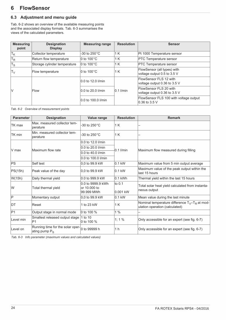
6 x FlowSensor6.3 Adjustment and menu guideTab. 6-2 shows an overview of the available measuring points and the associated display formats. Tab. 6-3 summarises the views of the calculated parameters.
Tab. 6-2 Overview of measurement points
Measuring point
DesignationDisplay
Measuring range Resolution Sensor
TK Collector temperature -30 to 250°C 1 K Pt 1000 Temperature sensorTR Return flow temperature 0 to 100°C 1 K PTC Temperature sensorTS Storage cylinder temperature 0 to 100°C 1 K PTC Temperature sensor
TV Flow temperature 0 to 100°C 1 K FlowSensor (all types) withvoltage output 0.5 to 3.5 V
V Flow
0.0 to 12.0 l/min
0.1 l/min
FlowSensor FLS 12 with voltage output 0.36 to 3.5 V
0.0 to 20.0 l/min FlowSensor FLS 20 with voltage output 0.36 to 3.5 V
0.0 to 100.0 l/min FlowSensor FLS 100 with voltage output 0.36 to 3.5 V
Parameter Designation Value range Resolution Remark
TK max Max. measured collector tem-perature -30 to 250°C 1 K –
TK min Min. measured collector tem-perature -30 to 250°C 1 K –
V max Maximum flow rate
0.0 to 12.0 l/min
0.1 l/min Maximum flow measured during filling0.0 to 20.0 l/min0.0 to 40.0 l/min0.0 to 100.0 l/min
PS Self test 0,0 to 99.9 kW 0.1 kW Maximum value from 5 min output average
PS(15h) Peak value of the day 0,0 to 99.9 kW 0.1 kW Maximum value of the peak output within the last 15 hours
W(15h) Daily thermal yield 0.0 to 999.9 kW 0.1 kWh Thermal yield within the last 15 hours
W Total thermal yield0.0 to 9999.9 kWhor 10.000 to 99.999 MWh
to 0.1
0.001 kW
Total solar heat yield calculated from instanta-neous output
P Momentary output 0,0 to 99.9 kW 0.1 kW Mean value during the last minute
DT Reset 1 to 23 kW 1 K Nominal temperature difference TV–TR at mod-ulation operation (calculated)
P1 Output stage in normal mode 0 to 100 % 1 % –
Level min Smallest released output stage P1
1 to 100 to 100 % 1; 1 % Only accessible for an expert (see fig. 6-7)
Level on Running time for the solar oper-ating pump PS
0 to 99999 h 1 h Only accessible for an expert (see fig. 6-7)
Tab. 6-3 Info parameter (maximum values and calculated values)

6 x FlowSensor
FA ROTEX Solaris RPS4 - 04/2016 25
6.3.1 Fast accessAfter switching on, the Solaris R4 regulator carries out a self-test, where the display elements are switched on individually and the setting parameters of the user level are displayed. The following testing steps are carried out, and the results displayed for about 2 seconds (fig. 6-5):– Immediately after switching on, the start display appears
which shows the installed software version and the serial number of the device.
– During initial commissioning, the desired display language isqueried.
– After this, the current parameter settings which the user canchange are displayed.
– When the operating display appears, the self test is complete.– The functions of the solar operating pump PS and their oper-
ating status lights can only be tested manually, for safety rea-sons (see section 6.2.6).
6.3.2 Display during operationDuring operation, the display shows the system temperatures, maximum values, and calculated values. After the start display, the Solaris R4 regulator is automatically in operating display mode, an operating value is displayed and the associated indicator lights up.
You can navigate between the four temperature measuredvalues and the flow measured value (see tab. 6-2 and tab. 6-6) by pushing the arrow keys. Pressing the Info key displays the maximum values and thecalculated values (see tab. 6-3).
The left-hand column of the display serves as a status display:– "1" in the first line, solar operating pump PS normal operation
active.– "2" in the 2nd line, solar operating pump PS active with maxi-
mum output (booster).– "B" in the 3rd. line, burner block contact active (see
section 6.3.10) or a fault status (see section 7.2 "Trouble-shooting").
– "H" in the 4th. line, manual operating mode.
6.3.3 Setup menuThe Solaris R4 regulator parameters are displayed and changed in the menu.
Pressing the OK key once (>2 s) either activates the menu orreturns to the operating display. Briefly pressing the keyconfirms a selection, opens the next menu item, ordisplays [stored] for approx. 1 second after a value has beenchanged.In the selected parameter display, pressing the OK keyswitches over to the parameter changing mode.
In the menu (fig. 6-7) the active menu path is displayed in the first line, a cursor (">") in the left column indicates the next lower menu path or a parameter. From here, you navigate to the re-spective menu tree by means of the arrow keys: up (+ key) or down (– key).
The set value can be changed in accordance with the arrow keys. Briefly pressing an arrow key changes the value by one step, and continuous pressing speeds up the change.
If the desired parameter has been changed and the entire pa-rameter list has been scrolled down, you will arrive back to the se-lection menu [choice 2/2] and from there into the operating display (see fig. 6-7). The control unit starts working with the changed parameter value(s) immediately. The display always re-turns to the operating display mode after 10 minutes, provided that no key is pressed during this time.
Fig. 6-5 Fast access
So long as no manual adjustments are made or an event corresponding to tab. 7-2 produces a different display, the actuated measured value or information display remains active. It is activated again, even after
parameter changes or "Switching OFF-ON". If info parameters are displayed, a measuring point check light is not activated.
Fig. 6-6 Display during operation

26 FA ROTEX Solaris RPS4 - 04/2016
6 x FlowSensor
Fig. 6-7 Setup menu

6 x FlowSensor
FA ROTEX Solaris RPS4 - 04/2016 27
6.3.4 Password inputThe Expert level of the setup menu is protected by a password, which must be entered at the beginning of the setup menu. Also the Operator level can be protected. The user level and the expert level are shown in different colours in fig. 6-7.
Alternative quick access to the setting menu:After switching the controller on, during the start display, long push on the up arrow key (+).
As long as the system is being operated manually, no further password entry is required. Passwords remain valid for about 10 minutes after the last key has been pressed. After entering the password for the required level, the following display appears for about 2 seconds:– [user OK],– [specialist OK] or,– [Code wrong].
User passwordThis password is not activated in the factory setting of the Solaris R4 regulator. By entering a 4-digit number code, all the parameters adjustable in Operator level are protected against un-authorised access (child protection or caretaker function). The parameters of the Operator level can only be changed with the correct Operator password or if password protection has been disabled.
A user password can be activated and changed or reassigned in the following menu path: [choice 1/2] -> [Functions] -> [Change code] (see fig. 6-7):
Enter old password in data box [current 0000] and new one inthe data box [new 0000]. Hereby, every digit must be confirmed with the OK key.If the new password is issued again, enter the new passwordin both the data box [current 0000] and in data box [new 0000].
When the user password is activated, the menu path shows: [choice 1/2] only [Code 0000]. The user password only becomes active after 10 min or after theSolaris R4 regulator is restarted.
Technician passwordThe password is entered in the menu path: Enter [choice 1/2] under [Code 0000]. It activates all important systems parameters in the settings menu for technicians (see fig. 6-7).
6.3.5 Language selectionDuring initial commissioning, or after a total reset, the display (fig. 6-5) is retained during the start and a language choice is requested.
Use the arrow keys to select your language, and confirm itwith the OK key.
It is possible to select a different language later on via the menu item: [choice 1/2] -> [Functions] -> [Change language] (fig. 6-7).
Alternative quick access to the language selection:Simultaneous pushing of the OK key and the up arrow key (+).
6.3.6 Setting and resetting parametersSetting the parameters is in accordance with fig. 6-7. All ad-justable parameters are shown with access level, adjustment range and factory setting in the tab. 6-5. In the menu path: [choice 1/2] -> [Parameter choice] -> [Reset] the maximum and calculated values can be reset (see tab. 6-5). Hereby, the se-lected max. value is set to zero immediately with the OK key. The arrow key "Down" cancels this operation, and the cursor goes back to the left. The OK key confirms the selection. Repeated pressing of the key "Down" takes you to the field [choice 2/2]. Actuation of [return] navigates to the operating display.
Using the menu path: [choice 2/2] -> [System] -> [Reset] you can trigger total reset function. The system is then restarted (see also section 6.2.10).
6.3.7 Setting the mounting position of the solar panel temperature sensor
A total reset deletes all individual settings and the event memory is deleted. All calculated values (info parame-ters) are set to zero.
If this total reset function is triggered via the menu path, the total thermal yield remains. This value is also deleted using the quick access via the button combinations.
Only if the solar panel temperature sensor has been mounted at the top on existing solar installations, will you need to change the factory setting " " of the param-eter [TKpos].
Fig. 6-8 Setting parameter [TKpos] with mounting position solar panel "Top"

28 FA ROTEX Solaris RPS4 - 04/2016
6 x FlowSensor6.3.8 Manual setting of the pump speed regulationWith certain output stages of the speed-regulated solar operating pump PS noise problems can sometimes arise. The current output of the selected stage is displayed in the bottom line [Flow rate] in the operating display (see fig. 6-6) as a percentage.
Make a note of the problematic output stage.Using the menu path: Navigate [choice 2/2] -> [System] ->[Modulation] to [Level] (see fig. 6-7).
Here, up to 10 speed ranges can be disabled. Next to the ref-erence number of the output stage (starting with 01 for the lowest output) and the operating status, the output of the relevant stage is displayed as a percentage under [performance].
Set noise-intensive stage under the parameter [active] to [no]. The stage is skipped when the solar operating pump PS is activated. Make a note of the problematic output stage It can be cancelled again by setting the parameter [active] to [yes] or by the total reset function.
6.3.9 Correction values for measuring points
If the measured value of a sensor deviates from the real value, it can be adjusted using a correction value.
Using the menu path: [choice 2/2] -> [System] -> [Correctionvalues] select the correction parameter (see fig. 6-7) andchange in accordance with tab. 6-4.
Tab. 6-4 Correction values for measured data
6.3.10 Cylinder temperature sensorThis contact controls an external heat generator in such a way that under favourable weather conditions, the storage cylinder is not heated by the external source. The connection cable offered as an accessory BSKK ( 16 41 10) is required. If the solar system reaches a momentary output, adjustable by the heating expert (menu path: [choice 1/2] -> [Parameter choice] -> [P min]) or if the storage tank has heated up to the adjustable minimum storage tank temperature set by the heating expert (operating pa-rameter [TS min] see tab. 6-5), the burner is deactivated via a contact, for example. The parameter setting for the burner blocking contact is described in fig. 6-7.
The parameter [time VBSK] makes it possible to set a delay in the switching timing for the burner blocking contact. The burner blocking contact only switches after expiry of the set delay time when the minimum storage tank temperature [TS min] is exceeded or if the set minimum momentary output for burner stop [P min] is exceeded (example see fig. 6-9).
In the following example (fig. 6-9) we show a fictional sequence of the storage tank temperature.
At time "t1" the minimum burner stop temperature, defined in the operating parameter "TS min", is exceeded for the first time. Since the storage tank temperature "TS" shortly afterwards falls back below this value, this does not lead to activation of the burner blocking contact.
Since the storage tank temperature "TS" is constantly exceeded at time "t2", this leads to activation of the burner blocking contact, with the delay "VBSK" at timet "t3". In a similar way, the burner blocking contact is only deactivated at time "t6".
These settings are only accessible after entering the expert password.
Designation/[Display]
Measurement & adjusting range
Factory value
Increment
Solar panel tempera-ture/[collector]
-9 to +9 0 K 1 K
Return flow tempera-ture/[Return]
-9 to +9 0 K 1 K
Storage tank tempera-ture/[Storage tank]
-9 to +9 0 K 1 K
Feed temepra-ture/[flow]
-9 to +9 0 K 1 K
Flow rate/[Flow] -2 to +2 0 l/min 0.1 l/min
0 Not active1 Activet Timet1...t6 Discrete timesBSK Cylinder temperature sensorTS Storage tank temperatureTS min Minimum temperature for burner stopVBSK Delay burner blocking contactFig. 6-9 For example: Function of the delay time when initiating the
burner blocking contact
6 x FlowSensor
FA ROTEX Solaris RPS4 - 04/2016 29
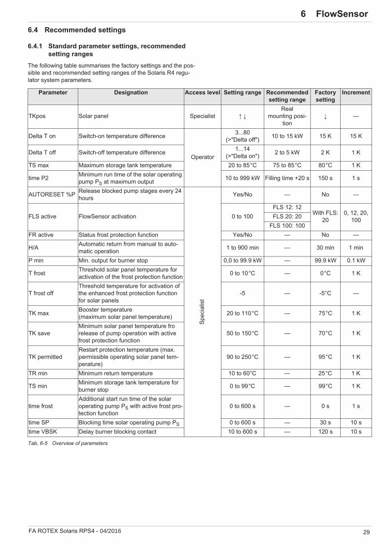
6.4 Recommended settings
6.4.1 Standard parameter settings, recommended setting ranges
The following table summarises the factory settings and the pos-sible and recommended setting ranges of the Solaris R4 regu-lator system parameters.
Tab. 6-5 Overview of parameters
Parameter Designation Access level Setting range Recommended setting range
Factory setting
Increment
TKpos Solar panel Specialist Real
mounting posi-tion
—
Delta T on Switch-on temperature difference
Operator
3...80(>"Delta off") 10 to 15 kW 15 K 15 K
Delta T off Switch-off temperature difference 1...14(>"Delta on") 2 to 5 kW 2 K 1 K
TS max Maximum storage tank temperature 20 to 85°C 75 to 85°C 80°C 1 K
time P2 Minimum run time of the solar operating pump PS at maximum output 10 to 999 kW Filling time +20 s 150 s 1 s
AUTORESET %P Release blocked pump stages every 24 hours
Spec
ialis
tYes/No — No —
FLS active FlowSensor activation 0 to 100FLS 12: 12
With FLS: 20
0, 12, 20, 100FLS 20: 20
FLS 100: 100FR active Status frost protection function Yes/No — No —
H/A Automatic return from manual to auto-matic operation 1 to 900 min — 30 min 1 min
P min Min. output for burner stop 0,0 to 99.9 kW — 99.9 kW 0.1 kW
T frost Threshold solar panel temperature for activation of the frost protection function 0 to 10°C — 0°C 1 K
T frost offThreshold temperature for activation of the enhanced frost protection function for solar panels
-5 — -5°C —
TK max Booster temperature(maximum solar panel temperature) 20 to 110°C — 75°C 1 K
TK saveMinimum solar panel temperature fro release of pump operation with active frost protection function
50 to 150°C — 70°C 1 K
TK permittedRestart protection temperature (max. permissible operating solar panel tem-perature)
90 to 250°C — 95°C 1 K
TR min Minimum return temperature 10 to 60°C — 25°C 1 K
TS min Minimum storage tank temperature for burner stop 0 to 99°C — 99°C 1 K
time frostAdditional start run time of the solar operating pump PS with active frost pro-tection function
0 to 600 s — 0 s 1 s
time SP Blocking time solar operating pump PS 0 to 600 s — 30 s 10 stime VBSK Delay burner blocking contact 10 to 600 s — 120 s 10 s
30 FA ROTEX Solaris RPS4 - 04/2016
6 x FlowSensor
The following instructions help with determining the setting values and guarantee optimum thermal yield with low power con-sumption:
Adjust the switch-on temperature difference [Delta T on] sothat the system remains in operation under constant solarradiation conditions, and does not switch off immediatelywhen the collector temperature drops due to heat removal.The lower this value can be adjusted, the longer will be theoperating periods with a correspondingly higher heat yield.If the adjusted switch-on temperature difference is too low,the collector will already cool down so far during filling, thatthe switch-off temperature difference is reached.
The pumps are switched off immediately, with resultinglower heat yield and higher power consumption.
Adjust the switch-off temperature difference [Delta T off] sothat the heat yield obtainable at the switch-off point is higherthan the electrical power required to drive the pump.
Since the power consumption of the solar operating pump PS is virtually independent of the size of the connected solar panel array, but the thermal power that can be exploited is directly dependent on the number of solar panels, the parameter value on a few solar panels is set higher, but with multiple solar panels it is set lower.
The run time [time P2] for maximum output of the solaroperating pump PS to be set so that, in all cases, the totalcross-section of the flow line is filled with water. Determinethe time from the detection of air noises from switching on the solar operating pump PS to entry into the storage tank andadd a safety factor of 20 secs. The filling period depends onthe adjusted flow rate, the number of collectors, systemheight, and the length of the connecting pipeThe maximum storage temperature [TS max] is set accordingto the individual conditions. The higher the value of theparameter, the higher will be the available heat storagecapacity, and thus the output potential of the ROTEX solarsystem.
System switch-on involving steam generation can often be disconcerting for the operator. In order to reduce boiling noises and steam emission, the restart temperature [TK permitted] is set in the factory. The Solaris R4 regulator only switches the solar operation pump PS on again when the collector temperature has fallen 2 Kelvin below the adjusted parameter value. Conse-quently, the system runs without evaporation in the collector. However, on a cloudless day, this can lead to a situation where the system only switches on again in the late afternoon, although
the storage cylinder temperature permits additional heating.In order to maximise energy input, set the [TK permitted] to avalue greater than 100°C and thus deactivate the restartprotection function.In this case the system operator should be advised of audiblebubbling noises and steam knocking during filling.
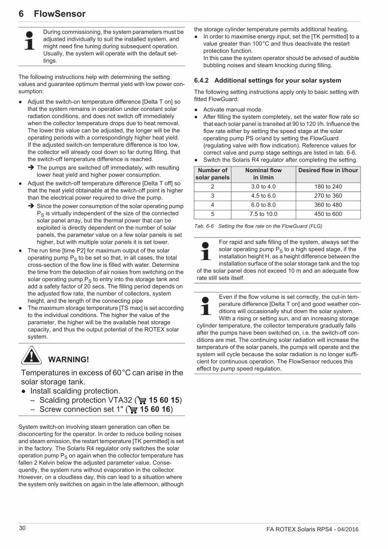
6.4.2 Additional settings for your solar systemThe following setting instructions apply only to basic setting with fitted FlowGuard:
Activate manual mode.After filling the system completely, set the water flow rate sothat each solar panel is transited at 90 to 120 l/h. Influence the flow rate either by setting the speed stage at the solaroperating pump PS or/and by setting the FlowGuard(regulating valve with flow indication). Reference values forcorrect valve and pump stage settings are listed in tab. 6-6.Switch the Solaris R4 regulator after completing the setting.
Tab. 6-6 Setting the flow rate on the FlowGuard (FLG)
During commissioning, the system parameters must be adjusted individually to suit the installed system, and might need fine tuning during subsequent operation. Usually, the system will operate with the default set-tings.
WARNING!Temperatures in excess of 60°C can arise in the solar storage tank.
Install scalding protection.– Scalding protection VTA32 ( 15 60 15)– Screw connection set 1" ( 15 60 16)
Number ofsolar panels
Nominal flow in l/min
Desired flow in l/hour
2 3.0 to 4.0 180 to 2403 4.5 to 6.0 270 to 3604 6.0 to 8.0 360 to 4805 7.5 to 10.0 450 to 600
For rapid and safe filling of the system, always set the solar operating pump PS to a high speed stage, if the installation height H, as a height difference between the installation surface of the solar storage tank and the top
of the solar panel does not exceed 10 m and an adequate flow rate still sets itself.
Even if the flow volume is set correctly, the cut-in tem-perature difference [Delta T on] and good weather con-ditions will occasionally shut down the solar system. With a rising or setting sun, and an increasing storage
cylinder temperature, the collector temperature gradually falls after the pumps have been switched on, i.e. the switch-off con-ditions are met. The continuing solar radiation will increase the temperature of the solar panels, the pumps will operate and the system will cycle because the solar radiation is no longer suffi-cient for continuous operation. The FlowSensor reduces this effect by pump speed regulation.

6 x FlowSensor
FA ROTEX Solaris RPS4 - 04/2016 31
6.4.3 Setting recommendation for the post-heating via external heat sources or by the electrical immersion heater, burner blocking contact
For the highest performance potential:Heat the solar storage tank only infrequently and then only toa just adequate temperature via the external heat source orelectrical immersion heater.Restrict the recharging times by means of timer programmes:a) Determine the optimum times for "normal use" by regular
consumption habits.b) Enable supplementary heating for 1/2 to 2 hours before
usual usage time depending on the external source.The charging time should be limited so that the cylinder doesnot need to be directly heated after a normal consumptioncycle.
If greater volumes of hot water are used and to maintaincomfortable temperatures during periods of unusual use, setthe temperature in the hot water zone to a sufficiently highlevel or enable the heat generator for supplementary heating, e.g. by switching to a different timer programme.
Setting the storage tank charging temperatureSet the hot water target temperature so that there is adequate hot water for drawing off (e.g. for one shower) at the lowestpossible setting value. This setting will guarantee themaximum heating of the hot water by the solar installation fora certain withdrawal quantity.
Heating by means of an external heat generatorDepending heating requirements (related to the building's insu-lation standard, outdoor temperature, and desired room temper-atures) and the installed collector surface, it might be expedient to disable the external heat generator by fitting a burner inhibit contact. For this purpose, also if the heater control demands ad-ditional heat:
Set the operating parameters [P min], [TS min] and [timeVBSK] in such a way that the external heat generator doesnot heat (see section 6.3.10),– if a a minimum heating output is provided by the solar pan-
els or– the storage cylinder has reached a sufficiently high tem-
perature.
6.4.4 Tips for optimised user behaviourHot water needs and user behaviour are highly individual. The higher the desired storage cylinder temperature is, and the longer the periods for non-solar charging heating have been ad-justed, the more will the storage potential for solar heat gener-ation be limited. Careful consumption behaviour, adapted to the particular strengths of the solar system minimises the energy consumption for non-solar charging processes.
Use modern and convenient shower heads with flow rates of5 - 7 l/min.
The lower flow rate (hot water consumption per minute)results in a reduced need for supplementary heating, and there-fore a larger amount of hot water at a higher temper-ature.
Reduce the consumption times.Lower energy consumption.
Start filling the bathtub only with hot water.After the domestic water stored in the solar storage tankhas been drawn off, the hot water outlet temperature drops slightly and the water is mixed in the bath. In this way, the storage capacity is used in an optimal manner with a minimum charging temperature; an adequate amount of hot water is available.
6.4.5 Domestic water hygieneIf no hot water is used for several days and the storage temper-ature of the Solaris system does not reach at least 60°C, for hy-giene reasons (Legionella protection) it is periodically heated up to above 60°C once or draw-off of the stored hot water (25 l) is recommended.
The optimum charging temperature depends on per-sonal needs; frequently a storage cylinder temperature of 50°C is adequate. An average shower requires about 30 to 50 l of hot water with an outlet temperature of
40°C. The cold water that flows into the storage tank when tak-ing a shower must be heated in the solar storage tank in a through-flow heating manner.

32 FA ROTEX Solaris RPS4 - 04/2016
7 x Faults and malfunctions7 Faults and malfunctions
7.1 Display of events
Using the menu path: [choice 2/2] -> [System] -> [incidence memory] and after entering the expert password (see section 6.3.4 and fig. 6-7) you can display the events arising the operation. For this purpose, the Solaris R4 regulator has a simple fault diagnosis system. The events memory stores nature and time of the event. The event is displayed in clear text and using a code, the time since the start of the event is displayed in hours. Starting with the most recent event, you can leaf through the in-
dividual events by means of the Info key. If the parameter [delete] in menu path: [choice 2/2] -> [System] -> [incidence memory] is on [yes], all events are deleted. Deletion of individual events is not possible. An overview of possible entries in the event memory is given in tab. 7-1.
Event code
Plain text display
Description Status display
(flashing)
Lamp (flashing)
Light (flashes)
0 collector Collector sensor: Short-circuited or open K TK
Long-term switch-off of PS1 Return Return flow sensor: Short-circuited or open R TR
2 Storage tank
Storage cylinder sensor: Short-cir-cuited or open S TS
3 Flow rate FlowSensor: Short-circuited or open DOperation without FlowSensor
4 flow FlowSensor: Short-circuited or open V5 A/D Internal A/D converter fault G
Long-term switch-off of PS6 alimenta-
tionInternal equipment fault of the supply voltage G
7 Reference Internal equipment fault of the refer-ence voltage G
8 RESET Overall reset was carried outParameters to factory settings, calculated values and event entries deleted (see chapter 6.2.10), equipment re-start
12 startflow
Minimum flow rate V1 (see tab. 6-1) not achieved in the start phase after expiry of [time P2] (description see chapter 6.2.1 and 6.2.12)
W Switch-off of PS for 2 h, then ready for oper-ation again or status "F"
F TVLong-term switch-off of PS, if an event arises 3x in a row without intermediate successful start.
13 TS > Tsmax
Storage tank maximum temperature ([TS max]) exceeded (description see chapter 6.2.1 and 7.2)
TS
Temporary switch-off of PS14 TR >> TS TR - TS > 10 K and TR > 40°C
(description see chapter 7.2) TR
15TK >
TK permitted
Permitted solar panel maximum tem-perature ([TK permitted]) exceeded - (description see chapter 6.2.1 and 7.2)
TK
16 Interrup-tion
Flow breakaway during operating phase detected (V < V2, see chapter 6.2.9 and tab. 6-1)
Temporary switch-off of PS (minimum for sta-bilisation time), blocking of current pump modulation stage, and the one below, refilling by PS for [time P2] at next switch-on condi-tion.
202 P-on Reset Switching on
Restart, all parameter settings and info parameters remain, automatically blocked pump output stages are released again.
204 Brown-Out Reset caused by prohibited reduction in the mains voltage Restart according to Code 202.
205 WatchdogReset caused by external interference influences (e.g. over-voltages caused by thunderstorms)
Restart according to Code 202.
Tab. 7-1 incidence memory

7 x Faults and malfunctions
FA ROTEX Solaris RPS4 - 04/2016 33
Sensor-specific error messages The Solaris R4 regulator reacts as follows when the cable is broken or in the event of a short circuit in the sensors or sensor cables (see tab. 7-2):– A flashing code letter in the display indicates the fault in the
status column and a message appears.– The lamp associated with the fault flashes.– In addition, the control unit automatically intervenes in system
operation.
All other sensor values remain accessible via the arrow keys.
Tab. 7-2 Sensor fault table
7.2 TroubleshootingOperating events similar to faultsThe storage tank temperature "TS" in the solar storage tank reaches the value set in the parameter [TS max]:– Pumps are switched off, the system is drained. In the
Solaris R4 regulator, the TS light flashes, the display showsthe measured storage tank temperature. As soon as the cyl-inder temperature falls more than 2 K, normal system opera-tion is resumed.
Temperature in the solar panel is higher than the restart protection temperature [TK permitted]:– Pumps are switched off. In the Solaris R4 regulator, the TK
light flashes. If the set switch-on inhibit temperature falls bymore than 2 K, normal system operation is enabled automat-ically.
Failures
Sensor Cause of the fault Status (blinks)
Display Lamp (flashing)
Light (flashes)
Collector temp.Interruption K uuuu TK
Long-term switch-off of PS
Short circuit –––– TK
Return flow temp.Interruption R uuuu TRShort circuit –––– TR
Storage cylinder temp.Interruption S uuuu TSShort circuit –––– TS
Inflow temp. Voltage drop V –––– without lampOperation without FlowSensor
FlowSensor Voltage drop D –––– without lamp
In this case, short-term evaporation in the collectors is possible. The unpressurised steam escapes into the cyl-inder. On rare occasions, small volumes of water vapour come out of the solar storage tank for short peri-ods.
WARNING!Live parts can cause an electric shock on contact and cause life-threatening burns and injuries.
Electrical installations must always be carriedout by qualified electrical technicians inconformity with the relevant electrical guide-lines and the regulations of the electricutilities company to prevent hazards fromdamaged electric wiring.Rectification of damage to live componentsof the RPS4 regulation and pump unit mustonly be carried out by heating engineersauthorised and recognised by the energysupply company.Before beginning the repair work, disconnectthe RPS4 regulation and pump unit from thepower supply (fuse, shut off main switch) andsecure against unintentional restart.Comply with the relevant safety at workregulations.
34 FA ROTEX Solaris RPS4 - 04/2016
7 x Faults and malfunctions
In the Solaris R4 regulator, the TR light flashes. Return temperature "TR" is greater than 40°C and is 10 K higher than the storage temperature "TS". The solar operating pump PS is switched off. The cause is a defective or incorrectly connected sensor.
Install the sensor correctly or replace it; normal systemoperation will be resumed.
In the status column of the Solaris R4 regulator, "W" flashes. The minimum flow rate start phase "V1" at the FlowSensor (see page 22, tab. 6-1) is not achieved after switching on the solar operating pump PS and expiry of the time defined via the parameter [time P2] (fig. 6-3).
The system goes to temporary blocking for 2 hours (solar operating pump PS is switched off), but still tries to restart automatically after the blocking time.If this event occurs three times in a row, without interme-diate starting, the solar operating pump PS is switched off for an extended period and the status "F" is set.
In the status column of the Solaris R4 regulator, "F" flashes. The minimum flow rate start phase "V1" at the FlowSensor (see page 22, tab. 6-1) is not achieved after switching on the solar operating pump PS and expiry of the time defined via the parameter [time P2] (fig. 6-3). The solar operating pump PS is switched off.
If a leak is suspected, examine the solar system, rectify faultsand then release the block by "Switching OFF/ON" on the controller.
If the system cannot be filled (Status "F"), even though the solar operating pump PS is actuated by the regulator, the following faults can be the cause:
1. Air drawn down when the system was running idle is in thesolar operating pump PS.
Check that the solar operating pump PS is running.The automatic vent must always be working! Check thesealing cap and loosen it if necessary (do not remove).
2. Check the installation for leaks.Check the installation for leaks and rectify if necessary.Follow instructions in section 5 "Start-up and decommis-sioning"".
3. The start run time [time P2] (chap. 6.4).
4. Check the installation for blockage. In frosty conditions, iceplugs can form in incorrectly run connecting pipes.
5. Check valve position on storage tank connection elbow.
If the display shows nothing and the main switch is in the illumi-nated "ON position":
Replace the control unit (electronic fault).
If the main switch is not illuminated in the "On" position, there is no power supply to the control unit.
Check the plug connection of the mains plug and the mainsconnection (fuse, switch).
If water vapour is continuously coming out of the solar storage tank when sunlight impinges, the flow rate is too small.
In this case, the system settings must be checked.
Special notes on electric sensors
Evaluate the display of the Solaris R4 regulator.Remove casing of the Solaris R4 regulator and remove anddisconnect the relevant sensors.Examine the contact positions of the affected sensors, andmeasure the resistance (or the DC voltage for flow temper-ature and flow rate sensors) on the sensor end.
When the fault has been rectified, the system automatically re-sumes normal operation and is in the operating mode.
The resistance or DC voltage values of the sensors are listed in fig. 9-1 and in fig. 9-2. Internal faults in the controller electronics that can be diagnosed are displayed in the display in accordance with tab. 7-1 (Status "G"). They also cause a safety switch-off of the pumps. Switching the system off and then on again after 2 minutes might remedy the fault; if not, the control unit must be replaced.
CAUTION!Danger of burning on hot surfaces.
Let the device cool down for a reasonablylong time before maintenance and inspectionwork.Wear protective gloves.
Only original ROTEX replacement parts may be used.
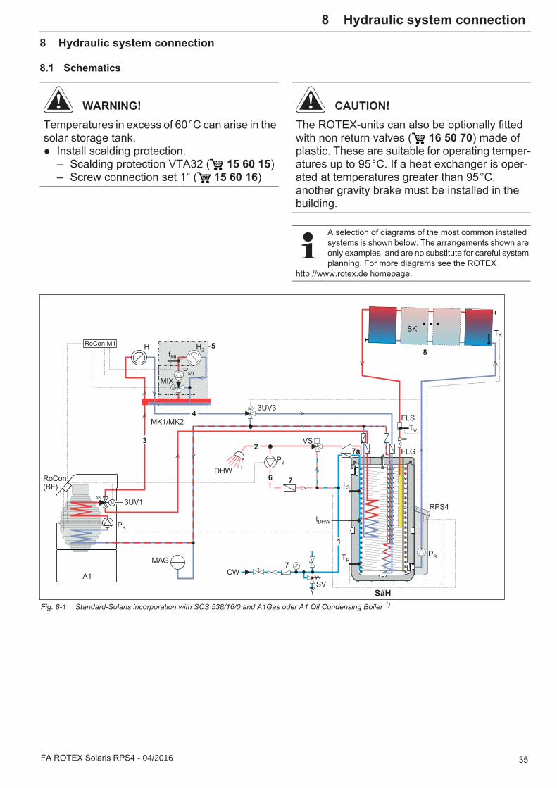
8 x Hydraulic system connection
FA ROTEX Solaris RPS4 - 04/2016 35
8 Hydraulic system connection
8.1 Schematics
WARNING!Temperatures in excess of 60°C can arise in the solar storage tank.
Install scalding protection.– Scalding protection VTA32 ( 15 60 15)– Screw connection set 1" ( 15 60 16)
CAUTION!The ROTEX-units can also be optionally fitted with non return valves ( 16 50 70) made of plastic. These are suitable for operating temper-atures up to 95°C. If a heat exchanger is oper-ated at temperatures greater than 95°C, another gravity brake must be installed in the building.
A selection of diagrams of the most common installed systems is shown below. The arrangements shown are only examples, and are no substitute for careful system planning. For more diagrams see the ROTEX
http://www.rotex.de homepage.
Fig. 8-1 Standard-Solaris incorporation with SCS 538/16/0 and A1Gas oder A1 Oil Condensing Boiler 1)
PS
RPS4
FLS
SK
8
MIX
H2
PMI
tMI
M
5
PK
SV
7
1
CWMAG
DHW
23
4
6RoCon(BF)
RoCon M1
tDHW
3UV1
3UV3
AB BM
A
M
H1
S#H
VS7a
7 TS
PZ
TR
A1
MK1/MK2TV
FLG
TK

36 FA ROTEX Solaris RPS4 - 04/2016
8 x Hydraulic system connection
Fig. 8-2 Standard-Solaris incorporation with GCU compact 1)
Fig. 8-3 Standard-Solaris incorporation with Air-Water-Heat Pump HPSU compact1)

8 x Hydraulic system connection
FA ROTEX Solaris RPS4 - 04/2016 37
1) The displayed plant schematics do not claim to be complete and do not replace careful indoor planning.
Fig. 8-4 Standard-Solaris incorporation with Air-Water-Heat Pump (HPSU Bi-Bloc with room heating and cooling function) 1)

38 FA ROTEX Solaris RPS4 - 04/2016
8 x Hydraulic system connection
Short name. Meaning1 Cold water distribution network2 Hot water distribution network3 Heating flow4 Heating return flow5 Mixing circuit6 Circulation7 Check valve, return valve7a Non return valves8 Solar circuit9 Gas pipe (coolant)10 Fluid pipe (coolant)11 Storage tank flow12 Storage tank return flow3UV1 3-way switch valve (DHW)3UV2 3-way switch valve (cooling)3UV3 3-way switch valve (heating support)
3UVB1 3-way switch valve (heating, internal circuit regu-lated)
3UV DHW 3-way switch valve (DHW + heating support reg-ulated)
A1 A1 oil or gas condensing boilerBOyy Electric immersion heater (Booster Heater)BUxx Electric immersion heater (Backup-Heater)BV Bypass valveC Coolant compressorCW Cold waterDHW Domestic hot waterE Expansion valve
FLG FlowGuard Regulating valve with flow rate indi-cator
FLSFlow sensor, FlowSensor FLS 20 or alternative type as per tab. 6.1 (Flow and Feed Temperature Measurement)
GCU com-pact
GasCombiUnit-series (solar storage tank with integrated gas condensing equipment)
H1,H2 … Hm Heating circuitsHP-TR Main regulator heat pumpHPSU com-pact
HPSU compact-series (solar storage tank with integrated heat pump unit)
MAG Diaphragm expansion vesselMIX 3-way-mixer with drive motorMK1 Mixer group with high-efficiency pump
MK2 Mixer group with high-efficiency pump (PWM controlled)
P High-efficiency pumpPK Boiler circuit pumpPMi Mixing circuit pumpPS Solar operating pump + PZ Circulation pumpPWT Panel heat exchanger (condenser)RKHB Indoor unit HPSU Bi-Bloc heat pumpRLB Return temperature limiterRoCon HP Control HPSU compact
RoCon BF Regulation A1 condensing boilerRoCon M1 Mixer circuit controlRPS4 Solaris Control and pump unit RRHQ Outdoor unit HPSU Bi-Bloc heat pumpRRLQ Outdoor unitHPSU compact RT Room thermostatS#A HYC 343/19/0-DBS#H SCS 538/16/0-DBSAS1 Sludge and magnetic separatorSK Solar panel fieldSV Safety over-pressure valve
tAURocon OT1 exterior temperature sensor (included in scope of supply GCU compact)
tDHWStorage tank temperature sensor (included in the scope of supply)
tMi Mixer circuit flow temperature sensorTK Solar collector temperature sensorTR Solar return flow temperature sensorTS Solar storage cylinder temp. sensorTV Solar flow temperature sensorV Fan (vaporiser)VS Protection against scalding VTA32
Tab. 8-1 Short names in hydraulic drawings
Short name. Meaning

8 x Hydraulic system connection
FA ROTEX Solaris RPS4 - 04/2016 39
8.2 Connection of a pressure solar panel system
If the structural conditions do not permit mounting the solar panels above the storage tank or if the connecting line cannot be installed with a continuous gradient between the storage panel and the storage tank, you cannot use the depressurised ROTEX solar system (DrainBack) and thus the regulation and pump unit RPS4.
Instead, the heating system can be executed with the ROTEX solar pressure system. The following solar components can be used equally in both systems:
Solaris high-performance flat solar panels V21P, V26P, H26PSolaris On-roof, flat roof and in-roof mounting packagesSolaris Hot water storage tank
Other system components must only be used under system-spe-cific conditions.

40 FA ROTEX Solaris RPS4 - 04/2016
9 x Technical data9 Technical data
9.1 Product Fiche Energy labelling Regulation: (EU) 811/2013
Ecodesign Regulation: (EU) 813/2013
9.2 Regulation and pump unit RPS4
9.3 Sensor characteristics
Solar devicespumps + controls
/ Model names RPS4
AuxiliarySolpump [W] 3 .
Solstandby [W] 2Annual auxiliary electricity consumption Qaux
[kWh/a] 92
Details and precautions on installation, maintenance and assembly can be found in the installation and or operation manuals. Energy labels and product fiches for addition combinations, packages and other products can be found on www.rotex-heating.com.
Sound power in heating mode, measured according to the EN12102 under conditions of the EN14825.
This data is for comparison of Energy efficiencies according to Energy label directive 2010/30/EC, for correct selection of products for your application, contact your dealer. Depending on your application and the product selected an additional supplementary heater may have to be installed.
Tab. 9-1 Characteristic data for determination of the values for energy efficiency designation
Regulation and pump unit RPS4Dimensions H x W x D 230 x 815 x142 mmOperating voltage 230 V / 50 HzSolar operating pump Grundfos UPM3 15-145
Maximum electrical power consumptionRPS4During start: 65 W (115 W)*In normal mode: 15-65 W (modulated) (30-115 W)*
Solaris R4 regulator Digital differential temperature controller with plain text displayMax. electric power consumption of the control unit 2 W
Solar panel temperature sensor Pt 1000Storage cylinder and return flow temperature sensor PTC
Feed temperature and flow sensor FLS 20 (alternatively FLS 12, FLS 100)* The details in brackets apply if a second pump is installed.
Tab. 9-2 Technical data for control and pump unit
Switch-on inhibit temperatureSolaris sensor Sensor type Measured temperature in°C
-20 -10 0 10 20 30 40 50 60 70 80 90 100 110 120Sensor resistance in Ohm according to standard or manufacturer's indications
TR, TS PTC 1386 1495 1630 1772 1922 2080 2245 2418 2598 2786 2982 3185 3396TK Pt 1000 922 961 1000 1039 1077 1116 1155 1194 1232 1270 1308 1347 1385 1423 1461FlowSensor Sensor output voltage in VTV (0.5, - 3.5 V) 0.5 0.80 1.10 1.40 1.70 2.00 2.30 2,60 2,90 3.20 3,50Flow rate
FlowSensor FLS 20Measured flow in l/min0,0 2.0 4.0 6,0 8,0 10.0 12,0 14.0 16.0 18,0 20.0Sensor output voltage in V
V (0.36, - 3.5 V) 0,36 0,67 0,99 1,30 1.62 1.93 2.24 2.56 2.87 3,19 3,50
Tab. 9-3 Sensor table of the Solaris sensor
9 x Technical data
FA ROTEX Solaris RPS4 - 04/2016 41
9.4 Pump characteristic curve
RS Sensor resistance (PTC, Pt 1000)
t Temperature
Fig. 9-1 Resistance characteristic lines of the Solaris sensor
L Flow rateU Sensor output voltage
t Temperature
Fig. 9-2 Characteristic curves of the FlowSensor
Fig. 9-3 Pump characteristic curve
42 FA ROTEX Solaris RPS4 - 04/2016
10 x Notes10 Notes

11 x List of keywords
FA ROTEX Solaris RPS4•04/2016 43
11 List of keywordsC
Components . . . . . . . . . . . . . . . . . . 12Control
Info parameters . . . . . . . . . . . . . . . 7Manual operation . . . . . . . . . . . . . 21Overview . . . . . . . . . . . . . . . . . . . . 27Rectification . . . . . . . . . . . . . . . . . 27
Control and pump unit . . . . . . . . . . . 7Components . . . . . . . . . . . . . . . . . . 7Peak output . . . . . . . . . . . . . . . . . 10
Cylinder extension . . . . 6, 24, 29, 40Cylinder extension kit . . . . 20, 22, 29Cylinder temperature sensor . . .28, 31
DDanger of frost . . . . . . . . . . . . . . . . 17Decommissioning . . . . . . . . . . . . . . 17Design . . . . . . . . . . . . . . . . . . . . . . . . 6Display during operation . . . . . . . . . 39Disposal . . . . . . . . . . . . . . . . . . . . . 18
EElectric immersion heater . . . . . . . . 31Enhanced frost protection function . . . . . . . . . . . . . . . . . . . . . . 23Events memory . . . . . . . . . 23, 27, 32
FFast access . . . . . . . . . . . . . . . . . . . 25Fault codes . . . . . . . . . . . . . . . . . . . 32Filling time . . . . . . . . . . . . . . . . .16, 20Flow
Disposal . . . . . . . . . . . . . . . . .22, 30Drilling template . . . . . . . . . . .21, 25
Flow rateDisposal . . . . . . . . . . . . . . . . . . . . 34Drilling template . . . . . 6, 11, 12, 16Setting . . . . . . . . . . . . . . . . . .11, 12
FlowGuard . . . . . . . . . . . . . . . .11, 38FlowSensor . . . . . . . . . 23, 24, 27, 38Frost protection function . . . . . .20, 23
HHot water storage tank
RPS3 control and pump unit . . . . . . 7Hot water storage tanks
Technical data . . . . . . . . . . . . . . . 40
IInfo parameters . . . . . . . . . . . . . . . . . 7Installation . . . . . . . . . . . . . 20, 29, 34Instantaneous output . . . . . . . . . . . 35
MMalfunctions
Manual . . . . . . . . . . . . . . . . . . . . . 32Rectification . . . . . . . . . . . . . . . . . 33
Manual operation . . 6, 21, 22, 23, 25, 27, 28Minimum pump output . . . . . . .22, 23Momentary output . . . . . . . . . . . . . . 24Mounting position solar panel temperature sensor . . . . . . . . . . . . . 27
NNoise problems . . .11, 16, 22, 28, 30
OOperating mode . . . . . . . . . . . . . . . . 7Overview . . . . . . . . . . . . . . . . . . . . . 27
PParameters
Heating via external heat generator . . . . . . . . . . . . . . . . . . . 31Language selection . . . . . . . . . . . . 29Large installations . . . . . . . . . . . . . 31Overview . . . . . . . . . . . . . . . . . . . . 29
Peak outputControl . . . . . . . . . . . . . . . . . . . . . 13Cylinder extension . . . . . . . . . . . . 11FlowGuard . . . . . . . . . . . . . . 10, 11Temperature sensor . . . . . . . . . . . 12
Product description . . . . . . . . . . . . . 33
RRectification . . . . . . . . . . . . . . . . . . 27Reset . . . . . . . 22, 23, 24, 27, 28, 32
SSelf test . . . . . . . . . . . . . . . 23, 24, 25Setup menu . . . . . . . . . . . . . . . 23, 26
Equalising pipe . . . . . . . . . . . . . . . 27Shutdown . . . . . . . . . . . . . . . . 25, 32Solaris storage cylinder extension kit . . . . . . . . . . . . . . . . . . 17
Final . . . . . . . . . . . . . . . . . . . . . . . 18Temporary . . . . . . . . . . . . . . . . . . 17
Speed control . . . . . . . . . . . . . . . . . 22Decommissioning . . . . . . . . . . . . . 20Permanent . . . . . . . . . . . . . . . . . . 28
System concepts . . . . . . . . . . . . . . . . 9
TTechnical data
Control and pump unit . . . . . . . . . 40FlowSensor characteristic curves . . . . . . . . . . . . . . . . . . . . . . 41Temperature sensor . . . . . . . 40, 41
Technician reset . . . . . . . . . . . . . . . 21Technician reset Total heat yield . . . . . . . . . . . . . . . . . 20, 33Temporary . . . . . . . . . . . . . . . . 33, 34Thermal yield . . . . . . . . . . . . . 22, 30
Day . . . . . . . . . . . . . . . . . . . . . . . . 24Momentary output . . . . . . . . . . . . . 24Table of sensor faults . . . 23, 24, 27
UUsable models . . . . . . 23, 24, 25, 27
WWarranty . . . . . . . . . . . . . . . . . . . . . . 2Warranty period . . . . . . . . . . . . . . . . 2
RO
TEX
· FA
RO
TEX
Sol
aris
RP
S4
· Sub
ject
to c
hang
e an
d co
rrec
tion
· 008
.162
7444
_01
· 04/
2016