rotex sanicube inox...rotex sanicube inox high-efficiency hot water storage tank operating and...
TRANSCRIPT
ROTEX Sanicube INOXHigh-efficiency hot water storage tank
Operating and installation instructions
Type Continuous heat outputup to:
ROTEX SCS 328/14/0 27 kW
ROTEX SC 538/0/0 35 kW
ROTEX SC 538/16/0 35 kW
ROTEX SC 538/16/16 50 kW
ROTEX SCS 538/0/0 35 kW
ROTEX SCS 538/16/0 35 kW
ROTEX SCS 538/16/16 45 kW
Serial number
Customer
GBEdition 07/2008

Guarantee and conformity
2 FA ROTEX Sanicube - 07/2008
ROTEX assumes the additional guarantee for material and manufacturing faults in accordance with this statement at the start of the legal guarantee period. Within the warranty period, ROTEX undertakes to have the unit repaired free of charge by a person assigned by the company.
ROTEX reserves the right to replace the unit.
The warranty is only valid if the unit is used properly and if it can be proved that it was installed correctly by a specialist company. As evidence we recommend strongly completing the "Check list for start-up", page 17 and sending it to ROTEX if necessary.
Guarantee period
The warranty period begins on the day of installation (billing date of the installation company), however at the latest 6 months after the date of manufacture (billing date). The warranty period is not extended if the unit is returned for repairs or if the unit is replaced.
Guarantee period of hot water storage tank: 3 yearsGuarantee period of electric immersion heater: 2 years
Exclusion of warranty
Improper use, tampering with the unit and unqualified modifications immediately invalidate the warranty.
Dispatch and transport damage are excluded from the warranty.
The warranty explicitly excludes consequential costs, especially costs of installing and removing costs the unit.
Declaration of conformity
For the high-efficiency hot water storage tank ROTEX Sanicube INOX
We, ROTEX Heating Systems GmbH, declare under our sole responsibility that the products
Product Order No. Product Order No.
ROTEX SCS 328/14/0 16 50 10
ROTEX SC 538/0/0 16 50 15 ROTEX SCS 538/0/0 16 45 15
ROTEX SC 538/16/0 16 50 16 ROTEX SCS 538/16/0 16 45 16
ROTEX SC 538/16/16 16 50 17 ROTEX SCS 538/16/16 16 45 17
are ready for use products in terms of the EU Construction Products Directive and comply with the requirements of the following guideline.
89/106/EEC Construction Products Directive, Annex lll-2-ii-3
with reference to
EN 12897 Storage tank water heaters (reference for the type, only applicable in part)
Design modifications which have an influence on the technical data for the hot water storage tank quoted in the product description and on the intended use, in other words producing considerable changes, render this declaration of conformity invalid.
Güglingen, 1.7.2008 Dr Eng. Franz GrammlingManaging Director

Contents
3FA ROTEX Sanicube - 07/2008
1 Safety . . . . . . . . . . . . . . . . . . . . . . . . . . . . . . . . . . . . . . . . . . . . . . . . . . . . . . . . . . . . . . . . . . . . . . . . . . . . . . . . . . . 41.1 Observing Instructions. . . . . . . . . . . . . . . . . . . . . . . . . . . . . . . . . . . . . . . . . . . . . . . . . . . . . . . . . . . . . . . . . . . . . . . . . . . . . . . . . . . . 41.2 Warning signs and explanation of symbols . . . . . . . . . . . . . . . . . . . . . . . . . . . . . . . . . . . . . . . . . . . . . . . . . . . . . . . . . . . . . . . . . . . . . 41.3 Avoid danger . . . . . . . . . . . . . . . . . . . . . . . . . . . . . . . . . . . . . . . . . . . . . . . . . . . . . . . . . . . . . . . . . . . . . . . . . . . . . . . . . . . . . . . . . . . 51.4 Proper use. . . . . . . . . . . . . . . . . . . . . . . . . . . . . . . . . . . . . . . . . . . . . . . . . . . . . . . . . . . . . . . . . . . . . . . . . . . . . . . . . . . . . . . . . . . . . 51.5 Instructions for operating safety . . . . . . . . . . . . . . . . . . . . . . . . . . . . . . . . . . . . . . . . . . . . . . . . . . . . . . . . . . . . . . . . . . . . . . . . . . . . 5
2 Product description. . . . . . . . . . . . . . . . . . . . . . . . . . . . . . . . . . . . . . . . . . . . . . . . . . . . . . . . . . . . . . . . . . . . . . . . . 72.1 Design and components. . . . . . . . . . . . . . . . . . . . . . . . . . . . . . . . . . . . . . . . . . . . . . . . . . . . . . . . . . . . . . . . . . . . . . . . . . . . . . . . . . . 72.2 Brief description . . . . . . . . . . . . . . . . . . . . . . . . . . . . . . . . . . . . . . . . . . . . . . . . . . . . . . . . . . . . . . . . . . . . . . . . . . . . . . . . . . . . . . . . 82.3 Advantages . . . . . . . . . . . . . . . . . . . . . . . . . . . . . . . . . . . . . . . . . . . . . . . . . . . . . . . . . . . . . . . . . . . . . . . . . . . . . . . . . . . . . . . . . . . . 82.4 Accessories. . . . . . . . . . . . . . . . . . . . . . . . . . . . . . . . . . . . . . . . . . . . . . . . . . . . . . . . . . . . . . . . . . . . . . . . . . . . . . . . . . . . . . . . . . . . 9
2.4.1 Electric immersion heaters . . . . . . . . . . . . . . . . . . . . . . . . . . . . . . . . . . . . . . . . . . . . . . . . . . . . . . . . . . . . . . . . . . . . . . . . . . . . . 92.4.2 Non return valves . . . . . . . . . . . . . . . . . . . . . . . . . . . . . . . . . . . . . . . . . . . . . . . . . . . . . . . . . . . . . . . . . . . . . . . . . . . . . . . . . . . . 92.4.3 Dirt filter . . . . . . . . . . . . . . . . . . . . . . . . . . . . . . . . . . . . . . . . . . . . . . . . . . . . . . . . . . . . . . . . . . . . . . . . . . . . . . . . . . . . . . . . . . 92.4.4 Scalding protection . . . . . . . . . . . . . . . . . . . . . . . . . . . . . . . . . . . . . . . . . . . . . . . . . . . . . . . . . . . . . . . . . . . . . . . . . . . . . . . . . . . 92.4.5 Thermometer Set . . . . . . . . . . . . . . . . . . . . . . . . . . . . . . . . . . . . . . . . . . . . . . . . . . . . . . . . . . . . . . . . . . . . . . . . . . . . . . . . . . . . 92.4.6 Solaris storage tank extension set . . . . . . . . . . . . . . . . . . . . . . . . . . . . . . . . . . . . . . . . . . . . . . . . . . . . . . . . . . . . . . . . . . . . . . . 9
3 Set-up and installation . . . . . . . . . . . . . . . . . . . . . . . . . . . . . . . . . . . . . . . . . . . . . . . . . . . . . . . . . . . . . . . . . . . . . 103.1 Hydraulic system connection . . . . . . . . . . . . . . . . . . . . . . . . . . . . . . . . . . . . . . . . . . . . . . . . . . . . . . . . . . . . . . . . . . . . . . . . . . . . . . 103.2 Set-up . . . . . . . . . . . . . . . . . . . . . . . . . . . . . . . . . . . . . . . . . . . . . . . . . . . . . . . . . . . . . . . . . . . . . . . . . . . . . . . . . . . . . . . . . . . . . . . 123.3 Installation . . . . . . . . . . . . . . . . . . . . . . . . . . . . . . . . . . . . . . . . . . . . . . . . . . . . . . . . . . . . . . . . . . . . . . . . . . . . . . . . . . . . . . . . . . . 13
3.3.1 Overview of connections. . . . . . . . . . . . . . . . . . . . . . . . . . . . . . . . . . . . . . . . . . . . . . . . . . . . . . . . . . . . . . . . . . . . . . . . . . . . . . 133.3.2 Hydraulic connection. . . . . . . . . . . . . . . . . . . . . . . . . . . . . . . . . . . . . . . . . . . . . . . . . . . . . . . . . . . . . . . . . . . . . . . . . . . . . . . . . 143.3.3 Interconnection of several storage tanks. . . . . . . . . . . . . . . . . . . . . . . . . . . . . . . . . . . . . . . . . . . . . . . . . . . . . . . . . . . . . . . . . . 143.3.4 Filling the hot water heat exchanger . . . . . . . . . . . . . . . . . . . . . . . . . . . . . . . . . . . . . . . . . . . . . . . . . . . . . . . . . . . . . . . . . . . . . 153.3.5 Filling the storage tank (without Solaris System installed). . . . . . . . . . . . . . . . . . . . . . . . . . . . . . . . . . . . . . . . . . . . . . . . . . . . . 153.3.6 Filling the storage tank (with Solaris System installed) . . . . . . . . . . . . . . . . . . . . . . . . . . . . . . . . . . . . . . . . . . . . . . . . . . . . . . . 153.3.7 Filling the heating system and the storage tank charging circuit . . . . . . . . . . . . . . . . . . . . . . . . . . . . . . . . . . . . . . . . . . . . . . . . 153.3.8 Connecting the electric immersion heater (accessories) . . . . . . . . . . . . . . . . . . . . . . . . . . . . . . . . . . . . . . . . . . . . . . . . . . . . . . . 15
4 Start-up . . . . . . . . . . . . . . . . . . . . . . . . . . . . . . . . . . . . . . . . . . . . . . . . . . . . . . . . . . . . . . . . . . . . . . . . . . . . . . . . . 174.1 Initial start-up . . . . . . . . . . . . . . . . . . . . . . . . . . . . . . . . . . . . . . . . . . . . . . . . . . . . . . . . . . . . . . . . . . . . . . . . . . . . . . . . . . . . . . . . . 17
5 Operation and Maintenance . . . . . . . . . . . . . . . . . . . . . . . . . . . . . . . . . . . . . . . . . . . . . . . . . . . . . . . . . . . . . . . . . 185.1 Operation . . . . . . . . . . . . . . . . . . . . . . . . . . . . . . . . . . . . . . . . . . . . . . . . . . . . . . . . . . . . . . . . . . . . . . . . . . . . . . . . . . . . . . . . . . . . 18
5.1.1 Storage tank. . . . . . . . . . . . . . . . . . . . . . . . . . . . . . . . . . . . . . . . . . . . . . . . . . . . . . . . . . . . . . . . . . . . . . . . . . . . . . . . . . . . . . . 185.1.2 Electric immersion heater (accessory) . . . . . . . . . . . . . . . . . . . . . . . . . . . . . . . . . . . . . . . . . . . . . . . . . . . . . . . . . . . . . . . . . . . . 18
5.2 Service and maintenance. . . . . . . . . . . . . . . . . . . . . . . . . . . . . . . . . . . . . . . . . . . . . . . . . . . . . . . . . . . . . . . . . . . . . . . . . . . . . . . . . 19
6 Technical data . . . . . . . . . . . . . . . . . . . . . . . . . . . . . . . . . . . . . . . . . . . . . . . . . . . . . . . . . . . . . . . . . . . . . . . . . . . . 206.1 Basic data. . . . . . . . . . . . . . . . . . . . . . . . . . . . . . . . . . . . . . . . . . . . . . . . . . . . . . . . . . . . . . . . . . . . . . . . . . . . . . . . . . . . . . . . . . . . 206.2 Performance diagrams. . . . . . . . . . . . . . . . . . . . . . . . . . . . . . . . . . . . . . . . . . . . . . . . . . . . . . . . . . . . . . . . . . . . . . . . . . . . . . . . . . . 22
7 List of keywords . . . . . . . . . . . . . . . . . . . . . . . . . . . . . . . . . . . . . . . . . . . . . . . . . . . . . . . . . . . . . . . . . . . . . . . . . . 23

1 x Safety
1 Safety1.1 Observing Instructions
These instructions are intended for authorised and trained heating and sanitation experts who have experience in the proper installation and maintenance of heating systems and hot water storage tanks by virtue of their technical training and knowledge.
This manual provides all the necessary information for installation, start-up and maintenance, as well as basic information on operation and settings. Please go through the attached documents for a detailed description of operation and control.
Please read this manual carefully and thoroughly before proceeding with the installation or modification of the heating system.
Relevant documents– When connected to external heat generators; the associated installation and operating instructions.– When connecting a ROTEX Solaris installation; the associated installation and operating instructions.
1.2 Warning signs and explanation of symbols
Meaning of the warningsWarnings in this manual are classified according into their severity and probability of occurrence.
Special warning signsSome types of danger are represented by special symbols:
Order numberNotes related to Order numbers are identified by the cart symbol .
Handling instructions• Instructions on actions are shown as a list. Actions of which the sequential order must be maintained are numbered.
Results of actions are identified with an arrow.
DANGER!
Draws attention to imminent danger.
Disregarding this warning can lead to serious injury or death.
WARNING!
Indicates a potentially dangerous situation.
Disregarding this warning can result in serious injury or death.
CAUTION:
Indicates a situation which may cause possible damage.
Disregarding this warning can lead to damage to property and the environment.
This symbol identifies user tips and particularly useful information, but not warnings or hazards.
Electrical current Danger of burning or scalding
4 FA ROTEX Sanicube - 07/2008

1 x Safety
1.3 Avoid danger
The ROTEX Sanicube is state-of-the-art and is built to meet all recognised technical requirements. However, improper use can lead to serious injuries or death, as well as cause material damage. To prevent such risks, install and operate ROTEX Sanicube only:– as stipulated and in perfect condition,– with an awareness of the safety and hazards involved.This assumes knowledge and use of the contents of this manual, the relevant accident prevention regulations and the recognised safety-related and occupational medical rules.
1.4 Proper use
The ROTEX Sanicube may only be used as a hot water storage tank. The ROTEX Sanicube must be installed, connected and operated only according to the information in this manual.
Only those electric immersion heaters supplied by ROTEX may be used.
Any other use outside the above-mentioned use is considered as improper. Any resulting damages will be borne by the user/owner alone.
Intended use also includes compliance with the maintenance and service conditions. Spare parts must at least satisfy the technical requirements defined by the manufacturer. This is the case, for example, with original spare parts.
1.5 Instructions for operating safety
Before working on the hot water storage tank and the heating system• Work on the hot water storage tank and heating system (e.g. installation, connection and initial start-up) should only be
carried out by authorised and trained heating experts.• Switch off the mains supply before starting any work on the hot water storage tank and heating system and secure it against
unintentional switch-on.• Seals must not be damaged or removed.• Make sure that the safety valves comply with the requirements of EN 12828 when connecting on the heating side, and with
the requirements of EN 12897 when connecting on the domestic water side.
Electrical installation of optional accessories• Electrical installations may only be carried out by qualified electrical technicians under observance of the relevant electrical
guidelines and the regulations of the electric utilities company.• Compare the mains voltage indicated on the nameplate with the supply voltage before connecting to the mains.
Installation room• Only erect the ROTEX Sanicube if a ground load-bearing capacity of 1050 kg/m² plus safety factor is guaranteed. The ground
must be flat and level.• Erection outdoors is only possible to a limited extent. The storage tank must not be continuously exposed to direct sunlight.• The ROTEX Sanicube must be protected from frost.
Corrosion protectionIn a few regions, the water utility company supplies corrosive domestic water, which can result in corrosion damage even if high-quality stainless steel is used. Ask your water utility whether the use of hot water storage tanks made from stainless steel results in problems with corrosion in your area.
Suitable water treatment may be needed.
5FA ROTEX Sanicube - 07/2008 -
1 x Safety
Sanitary connection
With sanitary connection the following must be observed
• EN 1717 - Protection of domestic water from contamination in domestic water installations and general requirements concerning safety equipment for the prevention of domestic water contamination by back-flow
• EN 806 - Technical regulations for domestic water installations (TRWI)• and, in addition, the country-specific legal regulations.• During operation of the ROTEX Sanicube, the storage tank temperature may exceed 60 °C, particularly when solar power is
used. Therefore, some form of scalding protection needs to be included when you install the system (hot water mixing device, e. g. VTA32 15 60 16).
• Use a pressure reducer if the cold water connection pressure >6 bar.
Operation• Do not operate the ROTEX Sanicube if the storage tank is filled to above the overflow edge.• Operate the ROTEX Sanicube only with a set pressure reducer (max. 6 bar).
Instructing the user/owner• Before you hand over the heating system and the hot water storage tank, explain to the owner how he/she can operate and
check the heating system.• Document the hand-over by filling in and signing the checklist in Chapter 4 "Start-up", together with the operator.
6 FA ROTEX Sanicube - 07/2008
2 x Product description
2 Product description2.1 Design and components
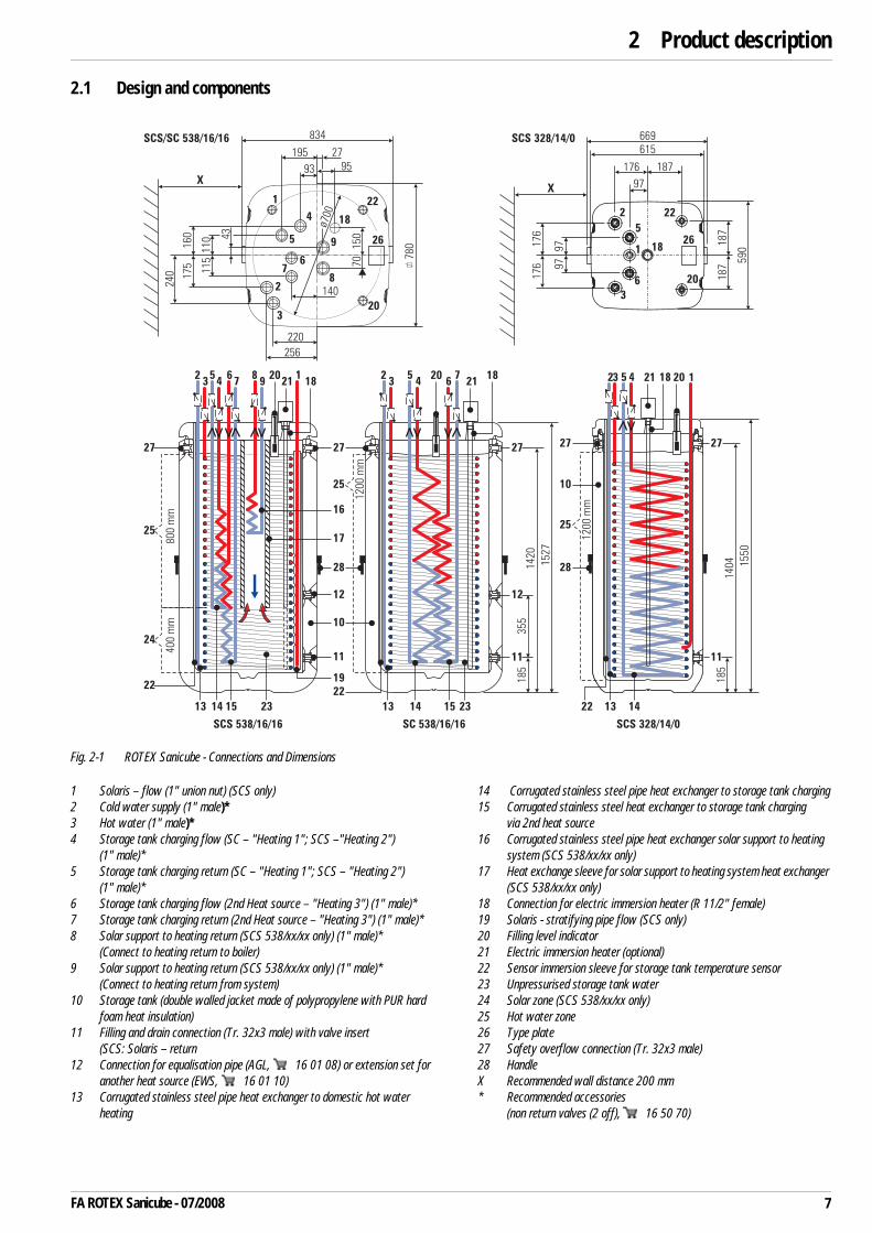
Fig. 2-1 ROTEX Sanicube - Connections and Dimensions
1 Solaris – flow (1" union nut) (SCS only)2 Cold water supply (1" male)*3 Hot water (1" male)*4 Storage tank charging flow (SC – "Heating 1"; SCS –"Heating 2")
(1" male)*5 Storage tank charging return (SC – "Heating 1"; SCS – "Heating 2")
(1" male)*6 Storage tank charging flow (2nd Heat source – "Heating 3") (1" male)*7 Storage tank charging return (2nd Heat source – "Heating 3") (1" male)*8 Solar support to heating return (SCS 538/xx/xx only) (1" male)*
(Connect to heating return to boiler)9 Solar support to heating return (SCS 538/xx/xx only) (1" male)*
(Connect to heating return from system)10 Storage tank (double walled jacket made of polypropylene with PUR hard
foam heat insulation)11 Filling and drain connection (Tr. 32x3 male) with valve insert
(SCS: Solaris – return12 Connection for equalisation pipe (AGL, 16 01 08) or extension set for
another heat source (EWS, 16 01 10)13 Corrugated stainless steel pipe heat exchanger to domestic hot water
heating
14 Corrugated stainless steel pipe heat exchanger to storage tank charging15 Corrugated stainless steel heat exchanger to storage tank charging
via 2nd heat source16 Corrugated stainless steel pipe heat exchanger solar support to heating
system (SCS 538/xx/xx only)17 Heat exchange sleeve for solar support to heating system heat exchanger
(SCS 538/xx/xx only)18 Connection for electric immersion heater (R 11/2" female)19 Solaris - stratifying pipe flow (SCS only)20 Filling level indicator21 Electric immersion heater (optional)22 Sensor immersion sleeve for storage tank temperature sensor23 Unpressurised storage tank water24 Solar zone (SCS 538/xx/xx only)25 Hot water zone26 Type plate27 Safety overflow connection (Tr. 32x3 male)28 HandleX Recommended wall distance 200 mm* Recommended accessories
(non return valves (2 off), 16 50 70)
SCS 328/14/0
SCS 328/14/0
SC 538/16/16SCS 538/16/16
SCS/SC 538/16/16 834 669
780
1
78
22
18
203
2
9
6
5
4
140
220
256
93
195
XX
ø700
27
95
43
110
115
160
175
240
150
70
26 26
800
mm
400
mm
2 2 23 3 35 5 54 4 466
897
7120 20 2021 21 211818 18
27
10
10
28
17
11 11
12
11
28
22
22
185
185
1404 1550
16
25
25
19
13 13 13 1414 1415 1523 23
27 27 27
1420
1527
1
97
176 187
187
97176
176 97 5
90
187
615
2
5
6
3
1 18
22
20
1200
mm
1200
mm
355
27
25
24
22
12
7FA ROTEX Sanicube - 07/2008

2 x Product description
2.2 Brief description
The ROTEX Sanicube is a combination of heat storage tank and instantaneous water heater.
The pressureless storage water serves as heat storage medium. Useful heat is supplied and removed via the spiral corrosion-resistant heat exchanger, which is made from a corrugated stainless steel pipe (1.4404), and is completely immersed in the storage tank water. In the heat exchanger for domestic hot water there are approx. 24 litres (19 l on SCS 328/14/0) of domestic water stored at the temperature level of the readiness zone.
The cold water which flows out when the hot water is removed is first routed to the storage tank at the very bottom of the heat exchanger, where it cools the lower area of the storage tank down as much as possible. The readiness zone is heated by an external heat generator (condensing boiler, Solaris, electric immersion heater). Water flows through the heat exchanger for storage charging (SL-WT) from top to bottom.
On its way to the top, the domestic water continuously absorbs the heat of the storage tank water. Since the flow direction makes use of the counter flow principle, and the heat exchanger is shaped like a spiral, there is definite temperature stratification within the storage tank. As high temperatures can be maintained for a very long time in the upper section of the storage tank, a high hot water output is achieved even if water is drawn off over a long period of time.
The hot water storage tank in the ROTEX Sanicube INOX Solaris can also be heated by solar energy. In the ROTEX Sanicube Solaris, the solar zone in the lower part of the tank is cooled by the cold water flowing in. Cooling also takes place on the heating side if the heating return temperature is lower than the temperature of the storage tank water. This means that the solar energy installation always operates at maximum efficiency and produces the maximum heat yield.
2.3 Advantages
Optimum water hygieneLow flow or unheated zones on the domestic water side are completely excluded with the ROTEX Sanicube. It is impossible for sludge, rust or other sediments to be deposited, as can be the case with other large volume tanks. The water which is fed into the system first is also discharged first (first in, first out principle).
Low maintenance and corrosionThe ROTEX Sanicube is made of plastic and is completely corrosion free. Sacrificial anodes or similar anti-corrosion units are not necessary. This means that associated maintenance work, e.g. changing the protective anodes or cleaning the storage tank, does not need to be carried out on the ROTEX Sanicube. Only the fill level of the storage tank water needs to be checked.
The corrugated stainless steel pipe heat exchangers on the heating and domestic water side are made from high quality stainless steel (1.4404).
Low scalingOn the storage tank side only one deposition of scale is possible. The immersion heater therefore remains clean, as do the stainless steel heat exchanger pipes in the storage tank water. This means that no scale can build up which would continuously reduce the efficiency of heat transfer in the course of operation (as is the case with other storage tank designs).
The thermal and pressure expansion and high flow rates in the domestic water heat exchanger release any possible scale deposits, which are then flushed away.
Economical operationThe full area heat insulation of the storage tank ensures very low heat losses in use and means that the best use is made of the heat energy being applied.
Modular extension facilityIf the heat output of a single ROTEX Sanicube is not adequate you can interconnect several storage tanks.
Electronic controlA control system integrated in the heat generator controls all heating and hot water functions for the direct heating circuit, a mixed heating circuit which can be connected as an option and a storage tank charging circuit.
SCS only : Settings, displays and functions of the Solaris heating are e.g. carried out by the regulating and pump station RPS3.
8 FA ROTEX Sanicube - 07/2008

2 x Product description
2.4 Accessories
2.4.1 Electric immersion heaters
In addition to the heating possibilities via the corrugated stainless steel pipe heat exchanger from various different heat sources and energy carriers, the ROTEX Sanicube can also be charged using an electric immersion heater.
2.4.2 Non return valves
In order to prevent heat losses from the connection pipes when the heating pump is switched off and during periods without domestic water being drawn off (gravity circulation) you should fit non return valves (set – 2 pcs, 16 50 70) in the connections to the ROTEX Sanicube.
2.4.3 Dirt filter
If the ROTEX Sanicube is connected to a heating system with steel pipes, radiators or non-diffusion-proof floor heating pipes, slurry and swarf could enter the hot water storage tank and cause blockages, local overheating or corrosion. This can be prevented by fitting a dirt filter.
– for units up to 28 kW: SFR 28 ( 15 60 11)– for units up to 50 kW: SFR 50 ( 15 60 12)
2.4.4 Scalding protection
There is a danger of scalding at hot water temperatures over 60 °C. The fitting of scalding protection means that the hot water temperature can be varied continuously and limited from 35–60 °C.
– Scalding protection VTA 32 ( 15 60 15)– Screw fittings set 1" ( 15 60 16)
2.4.5 Thermometer Set
The thermometer THSS ( 16 50 20) can be fitted for analogue display of the storage tank temperature.
2.4.6 Solaris storage tank extension set
ROTEX can supply the following components for interconnection of several ROTEX Sanicube Solaris to the Solaris installation:
– Solaris storage tank extension set CON SX ( 16 01 07)– Solaris FlowGuard ( 16 41 02)– Solaris FlowSensor ( 16 41 07)– Equalisation pipe for connection of 2 storage tanks AGL ( 16 01 08)
Type EHS/500/1 EHS/500/5 EHS/500/6
Operating voltage 230 V / 50 Hz 230/400 V / 50 Hz 230/400 V / 50 Hz
Heating output 2 kW 2, 4, 6 kW 2, 4, 6 kW
Temperature range1) 35–65 °C 30–78 °C 30–78 °C
Cable length 1.5 m — —
Heating element length 1.4 m 1.4 m 1.1 m
Screw-in thread R 1½" R 1½" R 1½"
Suitable for all SC + SCS2) all SC + SCS2) for SCS only
16 51 31 16 51 35 16 51 36
Tab. 2-1 Electric immersion heaters – overview and technical data1) Temperature regulation and a safety temperature limiter (STB) are already integrated in the
electric immersion heater. The electric immersion heater is delivered ready for fitting.2) The longer heating element in the SCS means that the Solar zone is also heated if electric
charging is used. This can reduce the efficiency of the Solaris system.
Fig. 2-2 Electric immersion heaters available
9FA ROTEX Sanicube - 07/2008

3x Set-up and Installation
3 Set-up and installation3.1 Hydraulic system connection
Fig. 3-1 Standard connection schematic drawing ROTEX Sanicube1)
Fig. 3-2 Standard connection schematic drawing ROTEX Sanicube Solaris1)
1 Boiler (e.g. ROTEX A1)2 Boiler circuit pump3 Diverter valve4 Hot water storage tank4.1 Storage tank4.2 Tank primary heat exchanger
(stainless steel corrugated pipe)
4.3 Domestic water heat exchanger (stainless steel corrugated pipe)
5 Storage tank sensor (re-charging)6 Cold water connection7 Hot water draw off point8 Circulation pump (optional)9 Heating flow line
10 Heating return line11 Storage charging pump (only with several
storage tanks connected together)12 Storage tank flow line13 Storage tank return line14 Non-return valve
SC 538/16/0
M
M
1000
1
2
34
24
4.1
4.3
4.2
5
6
7
8
9 10
12 13
14
14
15
16
18
19
17
H1 Hm......
1
2
3
6
9
10
12 13
14
15
1818
H1 Hm......
SCS 538/16/0
M
M
700
7
814
16
19
19
19
17
17
5
23
21 22
20
44.1
4.34.2
10 FA ROTEX Sanicube - 07/2008

3x Set-up and Installation
Fig. 3-3 Standard connection schematic diagram for connecting several ROTEX Sanicube (SC) (large scale installations) 1)
Fig. 3-4 Standard connection schematic diagram for connecting several ROTEX Sanicube Solaris (SCS) (large scale installations) 1)
15 Pressure relief valve16 Scalding protection (at storage tank
temperatures >60 °C)17 Cold water distribution network18 Non return valve (accessory)19 Air vent (accessory)
20 Solaris – Regulation and pump unit (optional)
21 Solaris – flow22 Solaris – return23 Solaris – collector field24 Safety overflow connection
(Accessory: Thermometer)
SC1, SC2, SCnROTEX Sanicube
SCS1, SCS2, SCSn-1,SCSnROTEX Sanicube Solaris
H1, HmHeating circuits
1) The installation schematic shown makes no claim to completeness and does not replace careful installation planning.
M M
17H1 Hm......
11
14 8
16
14 14
9 10
1
2
6
1415
12
13
7
SC1 SC2 SCn
181818
24 24 24
5
MM
SCS1 SCS2 SCSnSCS(n-1)
17
H1 Hm......
11
14 8
23 23
16
14 14
109
1
2
614
15
20
18 18 18
13
20
7
5
12
2424
11FA ROTEX Sanicube - 07/2008
3x Set-up and Installation
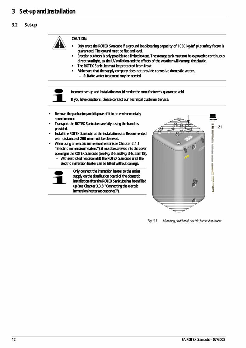
3.2 Set-up
CAUTION:
• Only erect the ROTEX Sanicube if a ground load-bearing capacity of 1050 kg/m² plus safety factor is guaranteed. The ground must be flat and level.
• Erection outdoors is only possible to a limited extent. The storage tank must not be exposed to continuous direct sunlight, as the UV radiation and the effects of the weather will damage the plastic.
• The ROTEX Sanicube must be protected from frost.• Make sure that the supply company does not provide corrosive domestic water.
– Suitable water treatment may be needed.
Incorrect set-up and installation would render the manufacturer's guarantee void.
If you have questions, please contact our Technical Customer Service.
• Remove the packaging and dispose of it in an environmentally sound manner.
• Transport the ROTEX Sanicube carefully, using the handles provided.
• Install the ROTEX Sanicube at the installation site. Recommended wall distance of 200 mm must be observed.
• When using an electric immersion heater (see Chapter 2.4.1 "Electric immersion heaters"), it must be screwed into the cover opening in the ROTEX Sanicube (see Fig. 3-5 and Fig. 3-6, Item 18).– With restricted headroom tilt the ROTEX Sanicube until the
electric immersion heater can be fitted without damage.
Fig. 3-5 Mounting position of electric immersion heater
Only connect the immersion heater to the mains supply on the distribution board of the domestic installation after the ROTEX Sanicube has been filled up (see Chapter 3.3.8 "Connecting the electric immersion heater (accessories)").
21
12 FA ROTEX Sanicube - 07/2008
3x Set-up and Installation
3.3 Installation
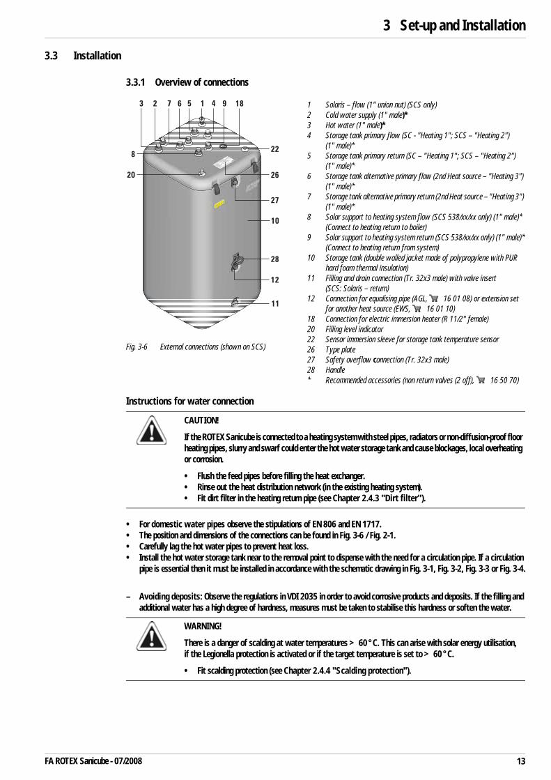
3.3.1 Overview of connections
Instructions for water connection
• For domestic water pipes observe the stipulations of EN 806 and EN 1717.• The position and dimensions of the connections can be found in Fig. 3-6 / Fig. 2-1.• Carefully lag the hot water pipes to prevent heat loss.• Install the hot water storage tank near to the removal point to dispense with the need for a circulation pipe. If a circulation
pipe is essential then it must be installed in accordance with the schematic drawing in Fig. 3-1, Fig. 3-2, Fig. 3-3 or Fig. 3-4.
– Avoiding deposits: Observe the regulations in VDI 2035 in order to avoid corrosive products and deposits. If the filling and additional water has a high degree of hardness, measures must be taken to stabilise this hardness or soften the water.
1 Solaris – flow (1" union nut) (SCS only)2 Cold water supply (1" male)*3 Hot water (1" male)*4 Storage tank primary flow (SC - "Heating 1"; SCS – "Heating 2")
(1" male)*5 Storage tank primary return (SC – "Heating 1"; SCS – "Heating 2")
(1" male)*6 Storage tank alternative primary flow (2nd Heat source – "Heating 3")
(1" male)*7 Storage tank alternative primary return (2nd Heat source – "Heating 3")
(1" male)*8 Solar support to heating system flow (SCS 538/xx/xx only) (1" male)*
(Connect to heating return to boiler)9 Solar support to heating system return (SCS 538/xx/xx only) (1" male)*
(Connect to heating return from system)10 Storage tank (double walled jacket made of polypropylene with PUR
hard foam thermal insulation)11 Filling and drain connection (Tr. 32x3 male) with valve insert
(SCS: Solaris – return)12 Connection for equalising pipe (AGL, 16 01 08) or extension set
for another heat source (EWS, 16 01 10)18 Connection for electric immersion heater (R 11/2" female)20 Filling level indicator22 Sensor immersion sleeve for storage tank temperature sensor26 Type plate27 Safety overflow connection (Tr. 32x3 male)28 Handle* Recommended accessories (non return valves (2 off), 16 50 70)
Fig. 3-6 External connections (shown on SCS)
CAUTION!
If the ROTEX Sanicube is connected to a heating system with steel pipes, radiators or non-diffusion-proof floor heating pipes, slurry and swarf could enter the hot water storage tank and cause blockages, local overheating or corrosion.
• Flush the feed pipes before filling the heat exchanger.• Rinse out the heat distribution network (in the existing heating system).• Fit dirt filter in the heating return pipe (see Chapter 2.4.3 "Dirt filter").
WARNING!
There is a danger of scalding at water temperatures >60 °C. This can arise with solar energy utilisation, if the Legionella protection is activated or if the target temperature is set to >60 °C.
• Fit scalding protection (see Chapter 2.4.4 "Scalding protection").
12 45673
8
9 18
22
26
27
20
10
28
12
11
13FA ROTEX Sanicube - 07/2008
3x Set-up and Installation
3.3.2 Hydraulic connection
1. When using non return valves (see Chapter 2.4.2 "Non return valves"), these should be fitted in the pipe connections on the ROTEX Sanicube.
2. Connect the drain hose to the safety overflow connection (Fig. 3-6 / Fig. 2-1, connection 27).
– Use transparent drain hose (draining water must be visible).– Connect the drain hose to an adequately dimensioned waste water installation.– Drain should not be lockable.
3. Check the water pressure at the cold water connection (<6 bar).
If the pressure in the domestic water supply is greater then fit a pressure reducer and limit the water pressure to <6 bar.
4. Establish a connection to the cold water supply (Fig. 3-6, connection 2).
5. Establish connections to the hot water distribution network.
6. Establish connections to the heating circuit.
– When connecting the heating side of the ROTEX Sanicube you must always ensure proper de-areation of the storage tank charging pipes (e.g. by the use of automatic vent valves at connections 4 to 9, Fig. 3-6 / Fig. 2-1).
7. Establish connections to the heat generator.
8. Establish connections to the Solaris System (optional).
– See Solaris installation and maintenance instructions.
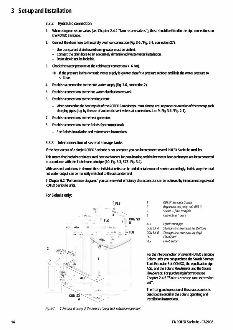
3.3.3 Interconnection of several storage tanks
If the heat output of a single ROTEX Sanicube is not adequate you can interconnect several ROTEX Sanicube modules.
This means that both the stainless steel heat exchangers for post-heating and the hot water heat exchangers are interconnected in accordance with the Tichelmann principle (SC: Fig. 3-3, SCS: Fig. 3-4).
With seasonal variations in demand these individual units can be added or taken out of service accordingly. In this way the total hot water output can be manually matched to the actual demand.
In Chapter 6.2 "Performance diagrams" you can see what efficiency characteristics can be achieved by interconnecting several ROTEX Sanicube units.
For Solaris only:
1 ROTEX Sanicube Solaris2 Regulation and pump unit RPS 3 3 Solaris – flow manifold4 Connecting T piece
AGL Equalisation pipeCON SX A Storage tank extension set (bottom)CON SX B Storage tank extension set (top)FLG FlowGuardFLS FlowSensor
For the interconnection of several ROTEX Sanicube Solaris units you can purchase the Solaris Storage Tank Extension Set CON SX, the equalisation pipe AGL, and the Solaris FlowGuards and the Solaris FlowSensor. For purchasing information see Chapter 2.4.6 "Solaris storage tank extension set".
The fitting and operation of these accessories is described in detail in the Solaris operating and installation instructions.
Fig. 3-7 Schematic drawing of the Solaris storage tank extension equipment
14 FA ROTEX Sanicube - 07/2008

3x Set-up and Installation
3.3.4 Filling the hot water heat exchanger
1. Open the shutoff valve for the cold water supply pipe.
2. Open the hot water tap connections so that the draw-off volume can be set as high as possible.
3. Once water has been discharged from the tap connections, do not interrupt the cold water inflow; this will ensure that the heat exchanger will be fully vented and that any impurities or residue will be discharged.
3.3.5 Filling the storage tank (without Solaris System installed)
1. Connect the filler hose with back flow preventer (½") via the hose connector provided to the filling and drain connection (Fig. 3-6, Item 11).
2. Fill the storage tank (Fig. 3-6, Item 10) until water comes out of the safety overflow connection (Fig. 3-6, Item 27).
3.3.6 Filling the storage tank (with Solaris System installed)
1. Connect the filling hose with return flow inhibitor (½") to the KFE cock on the control and pump unit (RPS).
2. Fill the storage tank (Fig. 3-6, Item 10) until water comes out of the safety overflow connection (Fig. 3-6, Item 27).
3.3.7 Filling the heating system and the storage tank charging circuit
• Fill and bleed the heating system and storage tank charging circuit in accordance with the installation and operating instructions for the particular heat generator.
3.3.8 Connecting the electric immersion heater (accessories)
EHS/500/1The EHS/500/1 is delivered ready to plug in.
1. Check the power supply voltage of the mains connection (~230 V, 50 Hz).
2. Insert the mains plug of the electric immersion heater into the plug socket.
EHS/500/5 and EHS/500/6
1. Check the power supply voltage of the mains connection (~230/400 V, 50 Hz).
2. Disconnect the junction box of the domestic electrical installation.
3. Install the electric cabling between the mains connection and the electric immersion heater.
WARNING!
Live parts can cause an electric shock on contact and cause fatal burns and injuries.
• Before beginning work on live parts, disconnect them from the power supply (switch off fuse, main switch) and secure against unintentional restart.
• The electrical connection should only be performed by electrical engineers in compliance with valid standards and guidelines as well as the specifications of the energy supply company.
15FA ROTEX Sanicube - 07/2008
3x Set-up and Installation
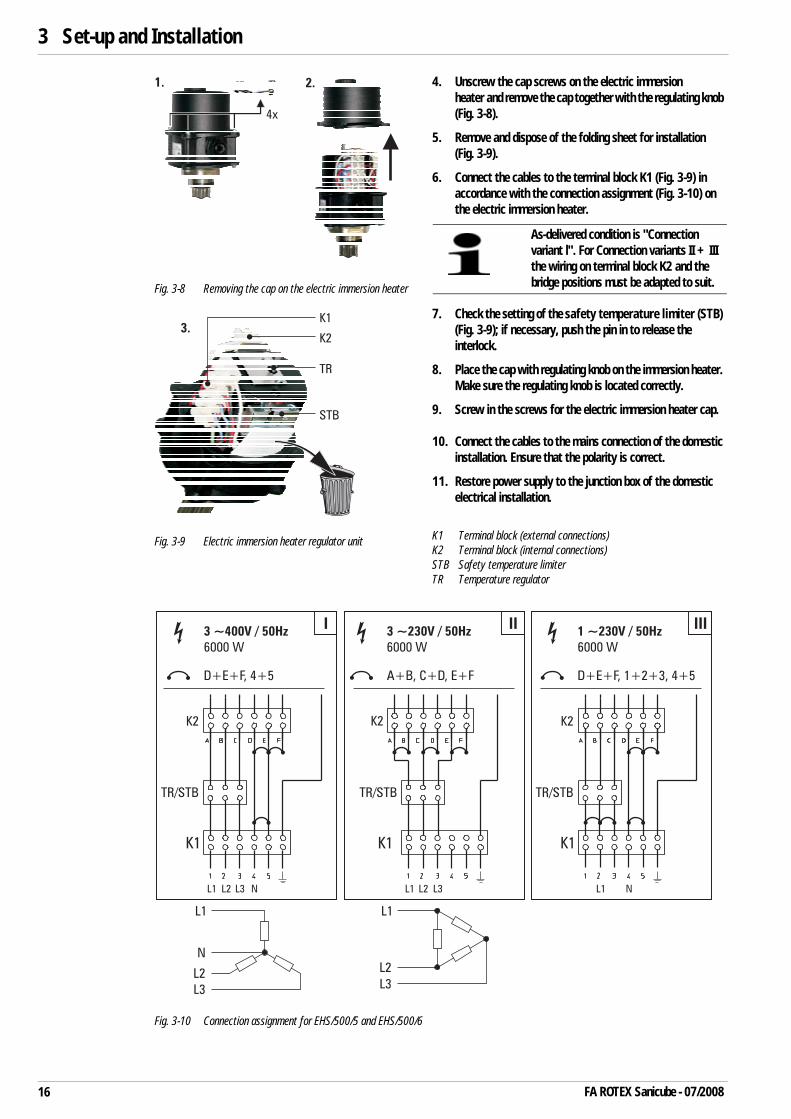
4. Unscrew the cap screws on the electric immersion heater and remove the cap together with the regulating knob (Fig. 3-8).
5. Remove and dispose of the folding sheet for installation (Fig. 3-9).
6. Connect the cables to the terminal block K1 (Fig. 3-9) in accordance with the connection assignment (Fig. 3-10) on the electric immersion heater.
7. Check the setting of the safety temperature limiter (STB) (Fig. 3-9); if necessary, push the pin in to release the interlock.
8. Place the cap with regulating knob on the immersion heater. Make sure the regulating knob is located correctly.
9. Screw in the screws for the electric immersion heater cap.
10. Connect the cables to the mains connection of the domestic installation. Ensure that the polarity is correct.
11. Restore power supply to the junction box of the domestic electrical installation.
K1 Terminal block (external connections)K2 Terminal block (internal connections)STB Safety temperature limiterTR Temperature regulator
Fig. 3-8 Removing the cap on the electric immersion heater
Fig. 3-9 Electric immersion heater regulator unit
Fig. 3-10 Connection assignment for EHS/500/5 and EHS/500/6
1.
4x
2.
As-delivered condition is "Connection variant l". For Connection variants II + III the wiring on terminal block K2 and the bridge positions must be adapted to suit.
3.K2
K1
TR
STB
I
L1
L2
L3
N
L1
L2
L3
3 ~400V / 50Hz
6000 W
D+E+F, 4+5
K2
TR/STB
K1
L1 L2 L3 N
II3 ~230V / 50Hz
6000 W
K2
TR/STB
K1
A+B, C+D, E+F
L1 L2 L3
III1 ~230V / 50Hz
6000 W
K2
TR/STB
K1
D+E+F, 1+2+3, 4+5
L1 N
16 FA ROTEX Sanicube - 07/2008
4 x Start-up
17FA ROTEX Sanicube - 07/2008
4 Start-up
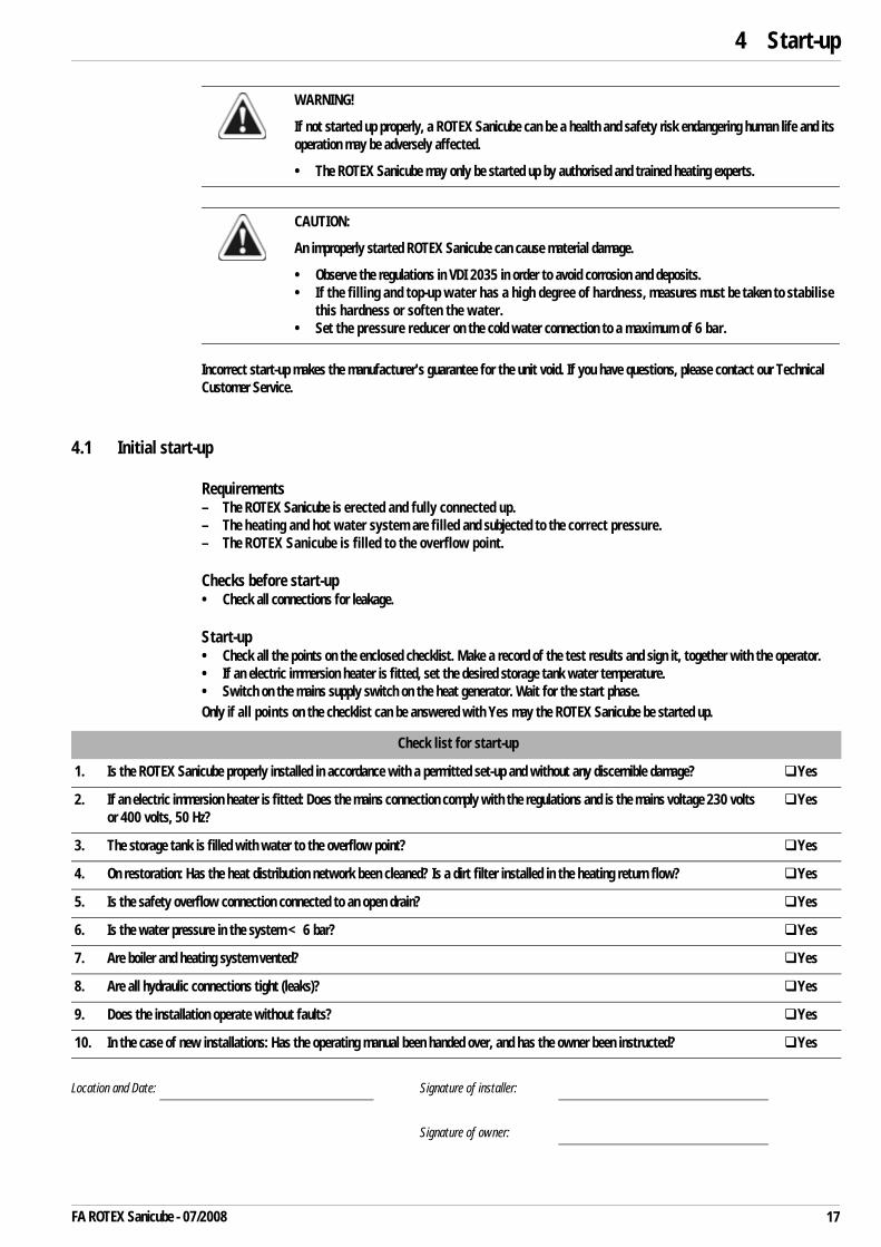
Incorrect start-up makes the manufacturer's guarantee for the unit void. If you have questions, please contact our Technical Customer Service.
4.1 Initial start-up
Requirements– The ROTEX Sanicube is erected and fully connected up.– The heating and hot water system are filled and subjected to the correct pressure.– The ROTEX Sanicube is filled to the overflow point.
Checks before start-up• Check all connections for leakage.
Start-up• Check all the points on the enclosed checklist. Make a record of the test results and sign it, together with the operator.• If an electric immersion heater is fitted, set the desired storage tank water temperature.• Switch on the mains supply switch on the heat generator. Wait for the start phase.Only if all points on the checklist can be answered with Yes may the ROTEX Sanicube be started up.
WARNING!
If not started up properly, a ROTEX Sanicube can be a health and safety risk endangering human life and its operation may be adversely affected.
• The ROTEX Sanicube may only be started up by authorised and trained heating experts.
CAUTION:
An improperly started ROTEX Sanicube can cause material damage.
• Observe the regulations in VDI 2035 in order to avoid corrosion and deposits.• If the filling and top-up water has a high degree of hardness, measures must be taken to stabilise
this hardness or soften the water.• Set the pressure reducer on the cold water connection to a maximum of 6 bar.
Check list for start-up
1. Is the ROTEX Sanicube properly installed in accordance with a permitted set-up and without any discernible damage? Yes
2. If an electric immersion heater is fitted: Does the mains connection comply with the regulations and is the mains voltage 230 volts or 400 volts, 50 Hz?
Yes
3. The storage tank is filled with water to the overflow point? Yes
4. On restoration: Has the heat distribution network been cleaned? Is a dirt filter installed in the heating return flow? Yes
5. Is the safety overflow connection connected to an open drain? Yes
6. Is the water pressure in the system <6 bar? Yes
7. Are boiler and heating system vented? Yes
8. Are all hydraulic connections tight (leaks)? Yes
9. Does the installation operate without faults? Yes
10. In the case of new installations: Has the operating manual been handed over, and has the owner been instructed? Yes
Location and Date: Signature of installer:
Signature of owner:

5 x Operation and Maintenance
5 Operation and Maintenance5.1 Operation
5.1.1 Storage tank
No separate controller is required to operate the ROTEX Sanicube. The regulation is effected in each case by the control system of the connected heat generator and, in the case of Solaris installations, by the Regulation and Pump Station.
• Check the level in the storage tank (see Chapter 2 "Product description", Fig. 2-1) at regular intervals and top up with water if required.
5.1.2 Electric immersion heater (accessory)
CAUTION!
If the electric immersion heater is used when the storage tank is not completely full this can lead to a reduction in heating efficiency and can cause an electrical fault under certain circumstances.
• Only use the electric immersion heater when the storage tank is completely full.
• Set the target temperature using the regulating knob on the electric immersion heater.– The ranges between positions B, C and D are
continuously adjustable.
Switch position
Regulating knob X
EHS/500/1 EHS/500/5EHS/500/6
A switched off (no frost protection)B frost protection only (~4–18 °C)
CTarget temperature
~50 °CTarget temperature
~55 °C
DTarget temperature
~65 °CTarget temperature
~78 °C
Fig. 5-1 Operating unit for electric immersion heater
X X
A
D
C
B
18 FA ROTEX Sanicube - 07/2008

5 x Operation and Maintenance
5.2 Service and maintenance
The ROTEX Sanicube is practically maintenance free as a result of its design. No corrosion protection equipment is required (such as sacrificial anodes). This means that associated maintenance work, e.g. changing the protective anodes or cleaning the inside of the storage tank, does not need to be carried out.
Regular inspection of the ROTEX Sanicube guarantees a long working life and fault-free operation.
Tests performed during the annual service:
– Visual check of general condition of the ROTEX Sanicube.– Visual check of connections and pipes. In the event of damage determine the cause
Replace defective parts.
– Check all electrical components, connections, and cables.
Repair damaged parts or replace them.
– Check the water pressure of the cold water supply (<6 bar)
and if necessary the fitting or adjustment of the pressure reducer.
– Visual check of the water storage tank level (water level at the overflow point).
If necessary, top up the supply water to the overflow point.
– Check the connection of the safety overflow and drain hose for leaks, free drainage and gradient.
If necessary clean the safety overflow and drain hose and and re-route, replace damaged parts.
Clean the storage tank (annually)• The low-maintenance plastic must only be cleaned with a soft cloth and a mild detergent.• Do not use cleaning agents containing aggressive solvents, as this will damage the plastic surface.
WARNING!
Live parts can cause an electric shock on contact and cause fatal burns and injuries.
• If there is an electric immersion heater or regulation and pump station installed in the ROTEX Sanicube then these components must be isolated from the power supply before starting the inspection and maintenance work (e.g. fuse, main switch switched off and secured against inadvertent switching on again).
WARNING!
All work performed on live components must be carried out in accordance with the proper procedures, otherwise there may be a danger to the life and health of individuals and the function may be impaired.
• Rectification of damage to live components must only be carried out by heating engineers authorised and recognised by the energy supply company.
19FA ROTEX Sanicube - 07/2008

6 x Technical data
6Tech
nica
l dat
a6.
1Ba
sic
data
ROTE
X Sa
nicu
be IN
OXRO
TEX
Sani
cube
INOX
Sol
aris
SCS
328/
14/0
SC 5
38/0
/0SC
538
/16/
0SC
538
/16/
16SC
S 53
8/0/
0SC
S 53
8/16
/0SC
S 53
8/16
/16
Basi
c da
taUn
it
Tota
l sto
rage
cap
acity
litre
s30
050
050
050
050
050
050
0
Empt
y w
eight
kg55
7884
9081
8793
Tota
l fille
d w
eight
kg33
557
858
459
058
158
759
3
Dim
ensio
ns (L
x B
x H
)cm
59.5
x 6
1.5
x 15
979
x 7
9 x
159
79 x
79
x 15
979
x 7
9 x
159
79 x
79
x 15
979
x 7
9 x
159
79 x
79
x 15
9
Max
imum
per
miss
ible
stor
age
tank
wat
er
tem
pera
ture
°C85
8585
8585
8585
Heat
con
sum
ptio
n at
read
ines
s an
d at
60
°CkW
h/24
h1.
31.
41.
41.
41.
41.
41.
4
Dom
estic
hot
wat
er (s
tain
less
ste
el 1
.440
4)
Dom
estic
wat
er c
apac
itylit
res
19.0
24.5
24.5
24.5
24.5
24.5
24.5
Max
imum
ope
ratin
g pr
essu
reba
r6
66
66
66
Dom
estic
wat
er h
eat e
xcha
nger
sur
face
m2
4.1
5.5
5.5
5.5
5.5
5.5
5.5
Aver
age
spec
ific
ther
mal
out
put
W/K
1820
2470
2470
2470
2470
2470
2470
1. S
tora
ge ta
nk c
harg
ing
heat
exc
hang
er (s
tain
less
ste
el 1
.440
4)
Wat
er c
onte
nt h
eat e
xcha
nger
litre
s10
.0—
10.4
10.4
—10
.410
.4
Heat
exc
hang
er s
urfa
ce a
rea
m2
2.1
—2.
32.
3—
2.3
2.3
Aver
age
spec
ific
ther
mal
out
put
W/K
910
—10
4010
40—
1040
1040
20 FA ROTEX Sanicube - 07/2008
6 x Technical data
2. S
tora
ge ta
nk c
harg
ing
heat
exc
hang
er (s
tain
less
ste
el 1
.440
4)
Wat
er c
onte
nt h
eat e
xcha
nger
litre
s—
——
10.4
——
10.4
Heat
exc
hang
er s
urfa
ce a
rea
m2
——
—2.
3—
—2.
3
Aver
age
spec
ific
ther
mal
outp
utW
/K—
——
1040
——
1040
Sola
r hea
ting
back
up (s
tain
less
ste
el 1
.440
4)
Wat
er c
onte
nt h
eat e
xcha
nger
——
——
22
2
Heat
exc
hang
er s
urfa
ce a
rea
m2
——
——
0.43
0.43
0.43
Aver
age
spec
ific
ther
mal
out
put
W/K
——
——
200
200
200
Ther
mal
out
put d
ata
N L e
ffici
ency
cha
ract
erist
ic ac
c. to
DIN
470
8 1)
2.2
4.1
4.1
4.4
/ 4.8
2)2.
32.
32.
5 / 2
.82)
Cont
inuo
us o
utpu
t QD
acco
rdin
g to
DIN
470
8kW
2735
3550
/ 50
2)35
3535
/ 45
2)
Max
imum
draw
-off
rate
for t
he du
ratio
n of 1
0m
in
on re
char
ging
at 3
5kW
(TKW
= 1
0°C
/ T W
W =
40
°C /
T SP=
60°C
)
l/min
2130
3031
/ 34
2)22
2224
/ 26
2)
Hot w
ater
qua
ntity
with
out r
ehea
ting
at 1
5l/m
in dr
aw-o
ff ra
te (T
KW
= 1
0°C
/TW
W =
40
°C/T
SP=
60°C
)
litre
s20
038
038
038
022
022
022
0
Hot w
ater
vol
ume
with
pos
t-hea
ting
at 1
5l/m
in
draw
-off
rate
(pos
t-cha
rge
outp
ut 2
0 / 3
5kW
) (T
KW=
10°C
/ T W
W=
40°C
/ T S
P=60
°C)
Litre
s at
20
kW40
083
783
784
344
244
245
3
Litre
s at
35
kW10
00un
limite
d(7
55)3)
unlim
ited
(755
)3)un
limite
d(1
280)
3)14
0014
00un
limite
d(5
25)3)
Shor
t-ter
m w
ater
qua
ntity
in 1
0m
inlit
res
210
300
300
310
220
220
230
Pipe
con
nect
ions
Hot a
nd c
old
wat
erin
ches
1" E
T1"
ET
1" E
T1"
ET
1" E
T1"
ET
1" E
T
Heat
ing
flow
and
retu
rn fl
owin
ches
1" E
T1"
ET
1" E
T1"
ET
1" E
T1"
ET
1" E
T
Orde
r num
ber
16 5
0 10
16 5
0 15
16 5
0 16
16 5
0 17
16 4
5 15
16 4
5 16
16 4
5 17
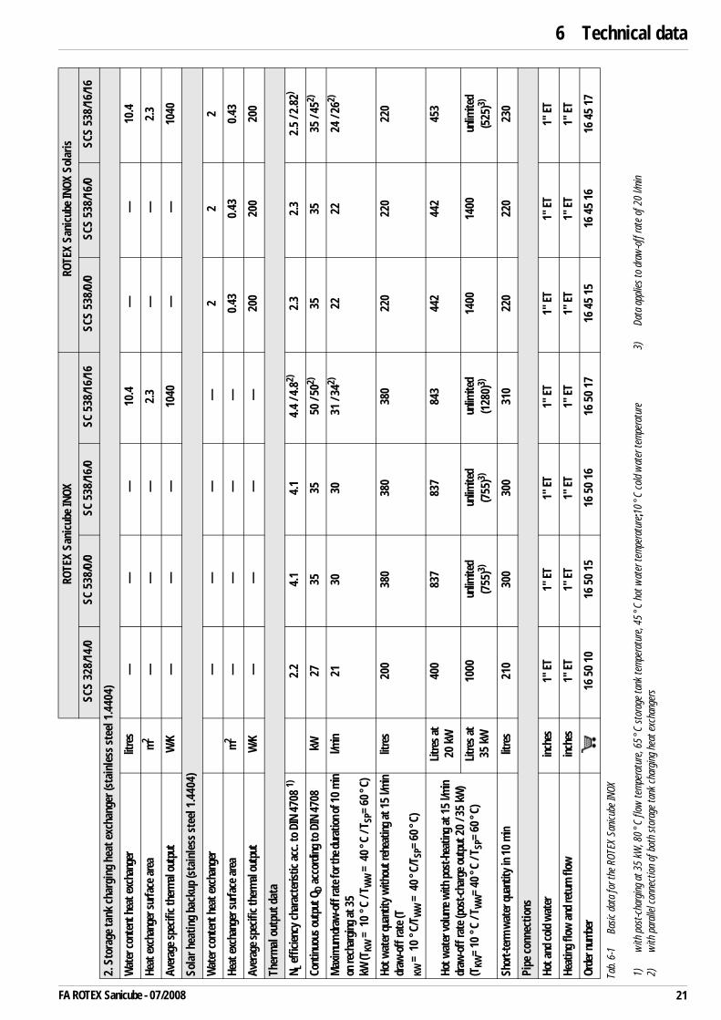
Tab.
6-1
Basic
dat
a fo
r the
ROT
EX S
anicu
be IN
OX
1)
with
pos
t-cha
rgin
g at
35
kW, 8
0°C
flow
tem
pera
ture
, 65
°C st
orag
e ta
nk te
mpe
ratu
re, 4
5°C
hot
wat
er te
mpe
ratu
re;1
0°C
cold
wat
er te
mpe
ratu
re2)
with
par
allel
con
nect
ion
of b
oth
stor
age
tank
cha
rging
hea
t exc
hang
ers
3)Da
ta a
pplie
s to
dra
w-o
ff ra
te o
f 20
l/min
ROTE
X Sa
nicu
be IN
OXRO
TEX
Sani
cube
INOX
Sol
aris
SCS
328/
14/0
SC 5
38/0
/0SC
538
/16/
0SC
538
/16/
16SC
S 53
8/0/
0SC
S 53
8/16
/0SC
S 53
8/16
/16
21FA ROTEX Sanicube - 07/2008
6 x Technical data
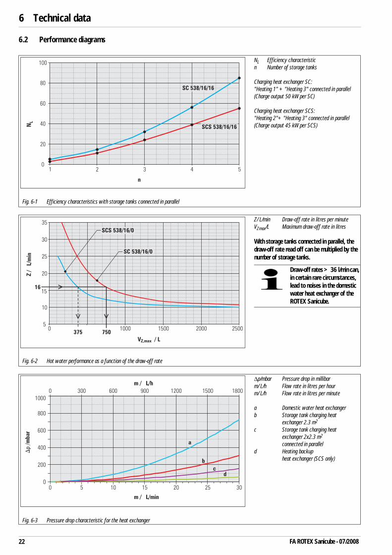
6.2 Performance diagrams
NL Efficiency characteristicn Number of storage tanks
Charging heat exchanger SC:"Heating 1" + "Heating 3" connected in parallel(Charge output 50 kW per SC)
Charging heat exchanger SCS:"Heating 2"+ "Heating 3" connected in parallel(Charge output 45 kW per SCS)
Fig. 6-1 Efficiency characteristics with storage tanks connected in parallel
Z/ L/min Draw-off rate in litres per minuteVZmax/L Maximum draw-off rate in litres
With storage tanks connected in parallel, the draw-off rate read off can be multiplied by the number of storage tanks.
Fig. 6-2 Hot water performance as a function of the draw-off rate
Δp/mbar Pressure drop in millibarm/ L/h Flow rate in litres per hourm/ L/h Flow rate in litres per minute
a Domestic water heat exchangerb Storage tank charging heat
exchanger 2.3 m2
c Storage tank charging heat exchanger 2x2.3 m2
connected in paralleld Heating backup
heat exchanger (SCS only)
Fig. 6-3 Pressure drop characteristic for the heat exchanger
Draw-off rates >36 l/min can, in certain rare circumstances, lead to noises in the domestic water heat exchanger of the ROTEX Sanicube.
22 FA ROTEX Sanicube - 07/2008

7 x List of keywords
23FA ROTEX Sanicube - 07/2008
7 List of keywordsAAutomatic vent valve . . . . . . . . . . . . 14
CCheck list for start-up . . . . . . . . . . . . 17Circulation pipe . . . . . . . . . . . . . . . . . 13Cleaning . . . . . . . . . . . . . . . . . . . . . . 19Connections and Dimensions . . . . . . . . 7Corrosion protection . . . . . . . . . . . . . . 5
DDangers . . . . . . . . . . . . . . . . . . . . . . . 5Design and components . . . . . . . . . . . . 7Dirt filter . . . . . . . . . . . . . . . . . . . . 9, 13Domestic water pipes . . . . . . . . . . . . 13Draw-off rate . . . . . . . . . . . . . . . . . . 22Draw-off volume . . . . . . . . . . . . . . . . 22
EEfficiency characteristic . . . . . . . . . . 22Electric immersion heater . . . . . . . . . . . . 9, 12, 16, 17, 18Electrical installation . . . . . . . . . . . . . . 5Electronic control . . . . . . . . . . . . . . . . 8Equalisation pipe . . . . . . . . . . . .7, 9, 13Explanation of symbols . . . . . . . . . . . . 4
FFilling . . . . . . . . . . . . . . . . . . . . . . . . 15
HHydraulic system connection . . . . . . . 10
IInstallation . . . . . . . . . . . . . . . . . . . . 13Installation room
Requirements . . . . . . . . . . . . . . . . 5Instructions for operating safety . . . . . 5Interconnection of several storage tanks . . . . . . . . . . . . . . . . . . . . . . . . 14
LLarge scale installations . . . . . . . . . . 11
NNon return valve . . . . . . . . . . . .7, 9, 13
OOperating mode . . . . . . . . . . . . . . . . . . 8Operation . . . . . . . . . . . . . . . . . . . . . 18Overview of connections . . . . . . . . 7, 13
PPerformance diagrams . . . . . . . . . . . . 22Proper use . . . . . . . . . . . . . . . . . . . . . . 5
RRegulation and Pump Station . . . . . . . 18Relevant documents . . . . . . . . . . . . . . 4
SSacrificial anode . . . . . . . . . . . . . . 8, 19Safety . . . . . . . . . . . . . . . . . . . . . . . . .4Safety overflow connection . . . . 14, 19Safety temperature limiter . . . . . . . . 16Sanitary connection . . . . . . . . . . . . . . .6Scalding protection . . . . . . . . . . . . 9, 13Set-up . . . . . . . . . . . . . . . . . . . . . . . 12Solaris
FlowGuard . . . . . . . . . . . . . . . . . 14FlowSensor . . . . . . . . . . . . . . . . . 14Installation . . . . . . . . . . . . . . . . . 14Storage tank extension equipment . . . . . . . . . . . . . . . . 9, 14
Start-up . . . . . . . . . . . . . . . . . . . . . . 17Checklist . . . . . . . . . . . . . . . . . . . 17Requirements . . . . . . . . . . . . . . . 17
TTechnical data . . . . . . . . . . . . . . . . . 20Thermometer Set . . . . . . . . . . . . . . . . .9Type plate . . . . . . . . . . . . . . . . . . . . . .7
WWall distance . . . . . . . . . . . . . . . . . . 12Warning signs . . . . . . . . . . . . . . . . . . . .4Water hardness . . . . . . . . . . . . . 13, 17Water pressure . . . . . . . . . . . . . . . . . 14

Notes
24 FA ROTEX Sanicube - 07/2008
008.
1604
544_
00 ·
Erro
rs a
nd te
chni
cal m
odifi
catio
ns re
serv
ed ·
Orig
inal
inst
ruct
ions
008
.160
4549
_00
Germ
an ·
07/2
008