roundoff noise characteristics of a class of orthogonal...
TRANSCRIPT
IEEE TRANSACTIONS ON ACOUSTICS, SPEECH, AND SIGNAL PR( DCESSING, VOL. ASSP-23, NO. 5 , OCTOBER 1975 473
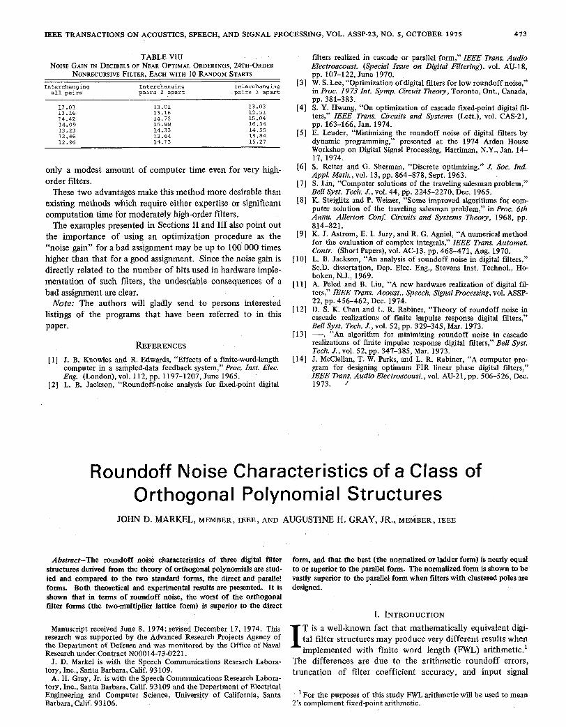
TABLE VI11 NOISE GAIN IN DECIBELS OF NEAR OPTIMAL ORDERINGS, 24TH-ORDER
NONRECURSIVE FILTER, EACH WITH 10 RANDOM STARTS I n t e r c h a n g i n g I n t e r c h a n g i n g
a l l p a i r s I n t e r c h a n g i n g
p a i r s 2 a p a r t p a i r s 3 a p a r t
13.01 - 13.16 14.42 14.09 13.23 13.46 12.96
13.01 13.16 14.72 15.88 14.33 13.64 14.13
13-03 13.51 15.04 16.34 14.55 15.84 15.27
only a modest amount of computer time even for very high- order filters.
These two advantages make this method more desirable than existing methods which require either expertise or significant computation time for moderately high-order filters.
The examples presented in Sections I1 and I11 also point out the importance of using an optimization procedure as the “noise gain” for a bad assignment may be up to 100 000 times higher than that for a good assignment. Since the noise gain is directly related to the number of bits used in hardware imple- mentation of such filters, the undesriable consequences of a bad assignment are clear.
Note: The authors will gladly send to persons interested listings of the programs that have been referred to in this paper.
REFERENCES [ 11 J. B. Knowles and R. Edwards, “Effects of a finite-word-length
computer in a sampled-data feedback system,” Proc. Inst. Elec. Eng. (London), vol. 112, pp. 1197-1207, June 1965.
[2] L. B. Jackson, “Roundoff-noise analysis for fixed-point digital
filters realized in cascade or parallel form,” ZEEE Trans. Audio Electroacoust. (Special Issue on Digital Filtering), vol. AU-18, pp. 107-122, June 1970. W. S. Lee, “Optimization of digital fiters for low roundoff noise,” in Proc. 1973 Int. Symp. Circuit Theory, Toronto, Ont., Canada,
S. Y. Hwang, “On optimization of cascade fixed-point digital ffi- ters,” IEEE Trans. Circuits and Systems (Lett.), vol. CAS-21, pp. 163-166, Jan. 1974. E. Leuder, “Minimizing the roundoff noise of digital fiters by dynamic programming,” presented at the 1974 Arden House Workshop on Digital Signal Processing, Harriman, N.Y., Jan. 14- 17, 1974. S. Reiter and G. Sherman, “Discrete optimizing,” J. Soc. Ind. Appl. Math., vol. 13, pp. 864-878, Sept. 1963. S. Lin, “Computer solutions of the traveling salesman problem,” Bell Syst. Tech. J., vol. 44, pp. 2245-2270, Dec. 1965. K. Steiglitz and P. Weiner, “Some improved algorithms for com- puter solution of the traveling salesman problem,” in Proc. 6th Annu. Allerton Con$ Circuits and Systems Theory, 1968, pp.
K. J. Astrom, E. I. Jury, and R. G. Agniel, “A numerical method for the evaluation of complex integrals,” ZEEE Trans. Automat. Contr. (Short Papers), vol. AC-13, pp. 468-471, Aug. 1970. L. B. Jackson, “An analysis of roundoff noise in digital filters,” Sc.D. dissertation, Dep. Elec. Eng., Stevens Inst. Technol., Ho- boken, N.J., 1969. A. Peled and B. Liu, “A new hardware realization of digital fil- ters,” ZEEE Trans. Acoust., Speech, Signal Processing, vol. ASSP- 22, pp. 456-462, Dec. 1974. D. S. K. Chan and L. R. Rabiner, “Theory of roundoff noise in cascade realizations of finite impulse response digital fiters,” Bell Syst. Tech. J . , vol. 52, pp. 329-345, Mar. 1973.
realizations of finite impulse response digital filters,” Bell Syst. Tech. J., vol. 52, pp. 347-385, Mar. 1973. J. McClellan, T. W. Parks, and L. R. Rabiner, “A computer pro- gram for designing optimum FIR linear phase digital filters,” ZEEE Trans. Audio Electroacoust., vol. AU-21, pp. 506-526, Dec. 1973. ’
pp. 381-383.
814-821.
- , “An algorithm for minimizing roundoff noise in cascade
Roundoff Noise Characteristics of a Class of Orthogonal Polynomial Structures
JOHN D. MARKEL, MEMBER, IEEE, AND AUGUSTINE H. GRAY, JR., MEMBER, IEEE
Abstract-The roundoff noise characteristics of three digital filter structures derived from the theory of orthogonal polynomials are stud- ied and compared to the two standard forms, the direct and parallel forms. Both theoretical and experimental results are presented. I t is shown .that in terms of roundoff noise, the worst of the orthogonal filter forms (the two-multiplier lattice form) is superior to the direct
Manuscript received June 8, 1974; revised December 17, 1974. This research was supported by the Advanced Research Projects Agency of the Department of Defense and was monitored by the Office of Naval Research under Contract N00014-73-0221.
J. D. Markel is with the Speech Communications Research Labora- tory, Inc., Santa Barbara, Calif. 93109.
A. H. Gray, Jr. is with the Speech Communications Research Labora- tory, Inc., Santa Barbara, Calif. 93109 and the Department of Electrical Engineering and Computer Science, University of California, Santa Barbara, Calif. 93106.
form, and that the best (the normalized or ladder form) is nearly equal to or superior to the parallel form. The normalized form is shown to be vastly superior to the parallel form when filters with clustered poles are designed.
I I. INTRODUCTION
T is a well-known fact that mathematically equivalent digi- tal filter structures may produce very different results when implemented with finite word length (FWL) arithmetic.’
The differences are due to the arithmetic roundoff errors, truncation of filter coefficient accuracy, and input signal
For the purposes of this study FWL arithmetic will be used to mean 2’s complement fixed-point arithmetic.

474 IEEE TRANSACTIONS ON ACOUSTICS, SPEECH, AND SIGNAL PROCESSING, OCTOBER 1975
quantization. For nontrivial filters, the roundoff errors are by far the most important contributor to the differences between the ideal (infinite word length) and FWL implementation.
Jackson and others [ 1 ] - ( 5 1 have developed the theory of roundoff noise effects in digital filters and shown very ac- curate predictions of the roundoff noise characteristics for a wide variety of filter types (low-pass, bandpass, etc.) under the assumption of rounding arithmetic. The basic filter structures (direct, parallel, and cascade) have been studied in detail. Jackson’s conclusion [ l ] was that a parallel structure exists that is usually superior to the best ordered configuration of a cascade structure in the sense of minimizing the X p norm IIN(e)ll, of the roundoff noise spectrumN(0) where
0 is the normalized frequency 2nf/F,, F, is the sampling fre- quency, and f is the unnormalized frequency.
Considerable research has been applied to the problem of finding alternate structures to minimize IIN(e)ll,. A particu- lar class of structures that has gained recent interest is the two input-two output form, generally implemented as a digital ladder or lattice filter [6] -[ 1 1 1 . It has been suggested that for at least one ladder form, the coefficient sensitivity was several bits less than for a cascade implementation [12] . Effects of roundoff noise based upon total filter implementation in a FWL format have not appeared in the literature.
The purpose of this paper is to present results from a study of the roundoff noise characteristics of a subclass of two input-two output structures, namely digital filter structures derived from the theory of orthogonal polynomials. For com- parative purposes the commonly accepted worst and best of the standard forms, namely the direct and the 1-P parallel form 131, are included. This study will focus upon the L2 norm ( p = 2) measure for roundoff noise computation due to its mathematical tractability and physical significance. Effects of input quantization and coefficient quantization only are not considered here.
A. Results 1 ) Theoretical roundoff noise equations have been derived
for the orthogonal forms and shown to be in excellent agree- ment with results obtained by simulation with rounding arithmetic.
2) In terms of roundoff noise characteristics due to FWL implementation, the worst of the orthogonal forms is in gen- eral the two-multiplier form [ l 1 1 . Under certain conditions the one-multiplier forms with constant sign parameters are worse than the two-multiplier form. The two-multiplier form appears to have similar (although always superior) FWL char- acteristics to the direct form.
3) The optimal one-multiplier form [ l 11 is superior to the two-multiplier and constant one-multiplier forms in general. In one series of elliptic low-pass filter designs, it mimicked the features of the parallel form with at most 6 dB or 1 bit of degradation over a wide range of bandwidths.
4 ) A newly developed orthogonal polynomial structure, the
normalized form [ 131 , has been shown to have nearly equal to or superior FWL characteristics to all of the other polynomial or standard forms. It appears to have vastly superior FWL characteristics over any other known filter structure for the implementation of tightly clustered poles. In a particular digital bandpass filter example the roundoff noise for the normalized form was shown to be 61 dB, or about 10 bits less than that of the parallel form.
A very important property of these orthogonal polynomial structures is that they are completely general, i.e., any stable direct form digital filter can be efficiently transformed using simple recursive relations [14] .
B. Approach Although a large number of structures can be derived from
the theory of orthogonal polynomials, three particular struc- tures will be concentrated upon in this paper. The first struc- ture (referred to as the two-multiplier form) is of interest because it is the most direct derivation from the theory. Ma- nipulation of this form leads to a one-multiplier form which has the property that it is canonic in multiplies and delays, and allows for a “sign-parameter” introduction for finding optimal scaling within the basic structure. Further manipulation leads to the “normalized” form which has the important property that the norms at every node in the all-pole portion are pre- cisely unity. For comparative purposes, the direct form and parallel form will also be used to implement each of the filters.
Both theoretical and experimental procedures will be used for determining the FWL characteristics of these filters. The parameter of major interest here will be the normalized noise roundoff variance or noise figure
v = u;/u2 (2)
where a i is the output roundoff noise variance defined by
. t-zn
with IN(e)12 being the output roundoff noise spectrum. The term uz defines the variance of the quantization step size b , and is given by
where 0 = b + 1 is the fured-point computer word length with b bits for magnitude and one bit for sign.
The theoretical procedure will follow Jackson’s approach except that the complete fdter will be scaled to insure against overflow in a fixed-point (fractional) representation.
After presenting the theoretical derivations and experimental procedures in more detail, a number of digital low-pass and bandpass filter examples will be discussed.
11. THEORETICAL PROCEDURES
A. Roundoff Noise Analysis for Direct and Parallel Forms Presentation of fmed-point roundoff noise comparisons
among the orthogonal polynomial filter forms and the stan-
MARKEL AND GRAY: ROUNDOFF NOISE CHARACTERISTICS
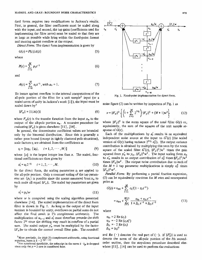
dard forms requires two modifications to Jackson's results. First, in general, the filter coefficients must be scaled along with the input, and second, the tap gains (coefficients used for implementing the filter zeros) must be scaled so that they are as large as possible while lying within the fixed-point format and insuring against overflow at the output.
Direct Form: The direct form implementation is given by
G(z) = P(z)/A(z) (5)
where
M P(z) = pjz-1 (6)
i = o
and
M A(z ) = , with a. = 1 . (7)
To insure against overflow in the internal computations of the all-pole portion of the filter for a unit sample' input (or a scaled norm of unity in Jackson's work [ 11 ), the input must be scaled down by3
i =o
IF, I I = I I 1/A(z)ll (8)
where F,(z) is the transfer function from the input x, to the output of the all-pole portion u,. A recursive procedure for evaluating [IF, 1 1 is given elsewhere [ 1 11 , [ 141 ,
In general, the denominator coefficient values are bounded only by the binomial distribution. Since this is generally a rather poor bound (except in tightly clustered pole situations), scale factors si are obtained from the coefficients as
s i = [log, {lai/, i = 1 , 2 , - . - , M } ] (9)
where [x] is the largest integer less than x. The scaled, frac- tional coefficients are then given by
a! = a.2-Si i = 1 , 2 , . . , M e I Z (10)
In the direct form, the scaling parameters si are applied to the all-pole portion. Only a constant scaling of the tap param- eter set { p i } is possible since the norms measured fromxn to each node all equal IlF, 11. The scaled tap parameters are given by
v,' = pJw (1 1)
where w is computed using the scaling algorithm presented elsewhere [ 141 . The scaled implementation of the direct form filter is shown in Fig. 1 . As long as the output of the input summer is bounded by unity, overflows on partial sums do not affect the final result in 2's complement arithmetic. The multiplication of u , - ~ and a: must therefore precede the shift factor 2'i since the shifting may result in overflow of a partial sum. The scaled output y; must be multiplied by the factor IlF,Ilw to obtain the correct overall filter gain. The roundoff
'More precisely, for 8-bit 2's complement arithmetic, using fractional
For notational simplicity, the subscript in the norm 11 . 11" is dropped notation, input is 1 - 2 4 3 - 1 )
3
I
'n-2
475
' n - M Fig. 1. Fixed-point implementation for direct form.
noise figure (2) can be written by inspection of Fig. 1 as
M v = llF,Il' { (i + 2"') llF~11' + (M + l)w'} (12)
i = 1
where IIF,,II' is the norm square of the total filter G(z) or, equivalently, the sum of the squares of the unit sample re- sponse of G(z).
Each 6f the multiplications by a: results in an equivalent independent noise source at the input to G'(z) (the scaled version of G(z) having variance 2"i uz). The output variance contribution is obtained by multiplying this term by the norm square of the scaled filter G'(z), IIF,,II'/w' times the gain squared from y; to y, , [IF, 11' w' . The input scaling from x, to x; results in an output contribution of 0: times IIF,,II'/w' times llF,llw'. The output noise contribution due to each of the M t 1 tap parameter multiplications is simply u: times IF, 11' w2 .
Parallel Fonn: By performing a partial fraction expansion, (5) can be equivalently rewritten for M even and nonrepeated poles as
where
vio = 2 Re ( c 2 )
~ 2 1 = - 2 Re ( c ~ z ; ) 021 = - 2 Re (zz) P2z = IZZI'
and Re ( * ) denotes the real part of ( + ). If IIF; II is used to denote the norm of the all-pole portion of the Zth second- order section, then the stepdown procedure described else-
since only the p = 2 case is considered here. ~~ r - -
where [ 1 1 J , [ 141 can be used to perform the evaluations

41 6 IEEE TRANSACTIONS ON ACOUSTICS, SPEECH, AND SIGNAL PROCESSING, OCTOBER 1915
and
as
where
kzo = Pz1 /(I + kZ1) kt1 =P22
0110 = %l/(l - k?o) 0111 = 1/(1 - k12,).
To insure against overflow within the all-pole portion of filter section E , the section input must be scaled down by llFuII for a unit sample input. Since I D l 2 I < 1 and I f i l l I < 2 for all 1, the scaled coefficients will be defined by
Although in some instances the scaling of Pzl by 2 is unneces- sary, this procedure will be followed throughout for simplicity. For the cases of most interest later, namely clustered pole conditions, the scaling is necessary. Since IlFhIl will generally be different for every section, the reciprocal factor must be included within the scaled taps as
4 0 = ~ l O I I F f , I l / W
d l = uz1 IIFf,ll/w
4 0 = voo/w (1 8)
and
for 1 = 1, 2, * . * , M/2, where w is computed by defining the maximum tap parameter value vmax as
urnax =max {Voo, Vzo, V l l , l = 1 , 2 , - - - , M / 2 } (19)
in the fixed-point scaling algorithm [14] . A block diagram of the fixed-point implementation of the parallel form is shown in Fig. 2. The roundoff noise figure v can be obtained from this figure as
v = 6 { llF;1I2 llFu\12} + (M + 1)w2. z = 1
If the fiter order is odd, or if any pole pairs are repeated, this development must be slightly modified.
Orthogonal Polynomial Foms: By making use of Mason's gain formula for flowgraphs [I51 , [ 161 the roundoff noise figure y for the three-orthogonal polynomial structures can be derived. The results are given below.
Two-multiplier form:
- 4 2 I
I
Fig. 2. Fixed-point implementation for parallel form.
One-multiplier form:
Normalized form:
where 11Fl1 defines the maximum norm within the filter, V$ defines the transfer function from node m in the upper path of the filter (denoted by m') to the output of the scaled filter, and V; defines the transfer function from node m in the lower feedback path of the filter (denoted by m-) to the out- put of the scaled filter.
Due to the number of feedback paths in these structures it is a nontrivial task to compute V; and VA. First the con- cept of equivalent sources will be applied to pull the noise sources out of each internal filter section. Next a right- and left-transfer function will be introduced for obtaining node to node transfer functions. Mason's gain formula for flowgraphs is then applied to compute the transfer functions from each noise source to the fiiter output.
EquivaZent Sources: In the two-multiplier model there are two multiplications per section. If these multiplications insert independent noise terms into the section m (whose input- output relations are denoted as G , (z)), the effect is equivalent

MARKEL AND GRAY: ROUNDOFF NOISE CHARACTERISTICS 477
to inserting noise sources outside the block at the nodes (m t 1)- and (m + l)', as shown in Fig. 3(a).
In the one-multiplier model the single internal noise source appears at both outputs of the section. The same effect can be realized by taking a single noise source q l , and inserting it into the nodes m+ and (m t I)-, provided the noise inserted into the nodes is negated for one of the nodes when the sign param- eter for that block is negative, as indicated in Fig. 3(b).
In the normalized form, there are four multipliers and hence four noise sources within each block. The same effect can be realized with external noise sources if two independent sources are fed into each of the output nodes m+ and (m + I)-, as shown in Fig. 3(c).
The noise analysis can thus proceed by treating the filter sections as having no internal noise sources. All noise sources are introduced externally at the appropriate nodes. The next step is to obtain node-to-node transfer functions so that the effect of the noise sources from each external node to the output can be evaluated. The internal structure of the sections labeled G,(z) for each of the three forms is shown elsewhere
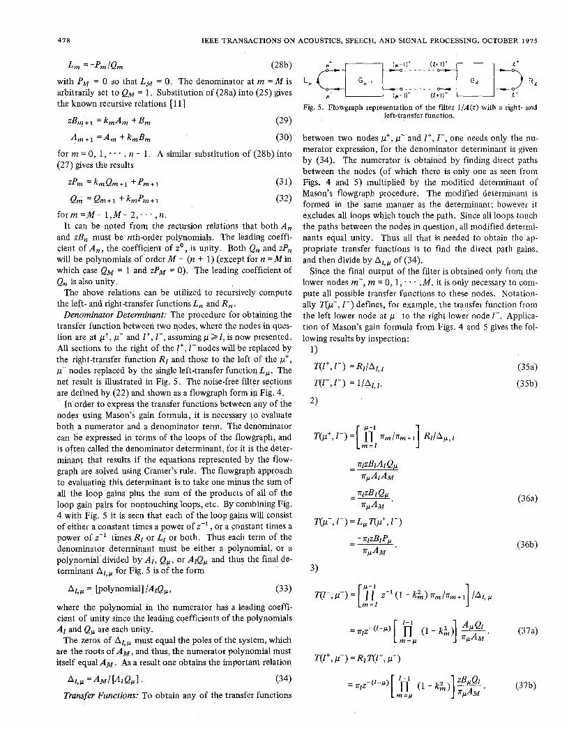
Left- and Right-Transfer Functions: In order to obtain node- to-node transfer functions, equivalent branches are found to represent right and left portions of the filter. This procedure is used to simplify the flowgraphs that will be obtained later. The filter is physically separated at the nodes n- and y1+, so that sections m = 0, 1, * - , y1 - 1 form the right portion and sections m = n, n + 1, . . 1 , M - 1 form the left portion. Start- ing with the right portion, a right-transfer function4 R, from an input at node n+ and an output at n- is defined. In a simi- lar manner a left-transfer function, L,, is defined from an input at node n- to an output at node n+.
By definition, Ro = 1 accounts for the boundary condition to the right of the 0th block, and LM = 0 accounts for the lack of feedback to the left of the Mth block. If the z transform values at the nodes m+ and m- are defined by XA and X;, respectively, then one can express all of the orthogonal poly. nomial filter forms by the equations
~ 3 1 , ~ 4 1 .
[~m/nm+1I x&+l =x& +km 2-l X i (224
[nm/nm+l] X;+1 =k,X& +Z-'X; (22b)
where the n, are the pi-parameters which are a function of the different filter structures as follows:
n, = 1 two-multiplier (23a) n, In, + = 1 + e, k , one-multiplier (23b) TI, = 1/( 1 - k$)1'2 normalized form. (234
A flowgraph representation of section m based upon (22), is shown in Fig. 4.
In terms of the node values from Fig. 4, the right-transfer function R, is
R, =X; /X&. (24)
4For notational simplicity, the explicit relationship to transfer func- tions as z transforms will be omitted except where necessary. For example, R, = R,(z) and A , = A,(z).
9, 0
9 3 '14
(c) Fig. 3. Equivalent noise models: (a) two-multiplier, (b) one-multiplier,
(c) normalized form.
nod; m'
Fig. 4. Flowgraph representation of section pn for the orthogonal poly- nomial structures.
Dividing (22b) by (22a) and substituting (24) results in a recursive evaluation for R, as
R m + 1 = k , t z-l R , 1 t k,z-' R ,
where m = 0, 1, . . * , n - 1 and Ro = 1. The left-transfer func- tion L , is defined in terms of the node variables as
Lm X $ / X i . (26)
Dividing (22a) by (22b), substituting (26), and solving for L, , results in a recursive evaluatiw for L, as
wherem=M- 1 ,M-2 ; . - , nandLM=0. I t i sknownf rom previous work that if X& is the input to the m section filter 1/A, at node m+, the output seen at node m- is given by zB, X; /A, where AI and El, I = 0, 1 , . * , M are each orthog- onal polynomials [l 1 ] . Therefore, in terms of the orthogonal polynomial relationships B, and A, ,
R, = zB, /A , ( 2 q
with A. = zBo = 1 so that Ro = 1. The left-transfer function is defined as the polynomial relation
478 IEEE TRANSACTIONS ON ACOUSTICS, SPEECH, AND SIGNAL PROCESSING, OCTOBER 1975
Lm = -Pm lQm (28b)
with PM = 0 so that LM = 0. The denominator at m = M is arbitrarily set to QM = 1. Substitution of (28a) into (25) gives the known recursive relations [ 1 I ]
zBT.1 =kmAm +Bm (29)
Am.1 =Am + kmBm (30)
for m = 0, 1, * . . , n - 1. A similar substitution of (28b) into (27) gives the results
ZPm =kmQm+l +Pm+l (3 1)
QA =Qm+1 +kmPm+1 (32)
f o r m = M - 1 , M - 2;.. , n . It can be noted from the recursion relations that both A ,
and zB, must be nth-order polynomials. The leading coeffi- cient of A , , the coefficient of zo , is unity. Both Q, and zP, will be polynomials of'order M - (n t 1) (except for n = M in which case QM = 1 and ZPM = 0). The leading coefficient of Q, is also unity.
The above relations can be utilized to recursively compute the left- and right-transfer functions L , and R,.
Denominator Determinant: The procedure for obtaining the transfer function between two nodes, where the nodes in ques- tion are at p+, p- and I+, I-, assuming p Z E , is now presented. All sections to the right of the Z', I - nodes will be replaced by the right-transfer function Rl and those to the left of the p', p- nodes replaced by the single left-transfer function L,. The net result is illustrated in Fig. 5. The noise-free filter sections are defined by (22) and shown as a flowgraph form in Fig. 4.
In order to express the transfer functions between any of the nodes using Mason's gain formula, it is necessary to evaluate both a numerator and a denominator term, The denominator can be expressed in terms of the loops of the flowgraph, and is often called the denominator determinant, for it is the deter- minant that results if the equations represented by the flow- graph are solved using Cramer's rule. The flowgraph approach to evaluating this determinant is to take one minus the sum of all the loop gains plus the sum of the products of all of the loop gain pairs for nontouching loops, etc. By combining Fig. 4 with Fig. 5 it is seen that each of the loop gains will consist of either a constant times a power of z - l , or a constant times a power of z-l times RE or Ll or both. Thus each term of the denominator determinant must be either a polynomial, or a polynomial divided by Al, Q,, or A l e , and thus the final de- terminant A , , for Fig. 5 is of the form
A z , ~ [~ol~nomia l l /AlQp, (33)
where the polynomial in the numerator has a leading coeffi- cient of unity since the leading coefficients of the polynomials A I and Q, are each unity.
The zeros of AI,, must equal the poles of the system, which are the roots of A M , and thus, the numerator polynomial must itself equal A M . As a result one obtains the important relation
AI,^ = A M I [ A I Q , I . (34)
Transfer Functions: To obtain any of the transfer functions
( q T P I ) + - - - - - -
L P R,
(p-1)- (1+1)-
Fig. 5 . Flowgraph representation of the filter l/A(z) with a right- and Ieft-transfer function.
- - - - - - .
between two nodes p', y- and l+, I-, one needs only the nu- merator expression, for the denominator determinant is given by (34). The numerator is obtained by finding direct paths between the nodes (of which there is only one as seen from Figs. 4 and 5 ) multiplied by the modified determinant of Mason's flowgraph procedure. The modified determinant is formed in the same manner as the determinant; however it excludes all loops which touch the path. Since all loops touch the paths between the nodes in question, all modified determi- nants equal unity. Thus all that is needed to obtain the ap- propriate transfer functions is to find the direct path gains, and then divide by A , , of (34).
Since the final output of the filter is obtained only from the lower nodes m-, m = 0,1, . . . ,M, it is only necessary to com- pute all possible transfer functions to these nodes. Notation- ally T&-, I-) defines, for example, the transfer function from the left lower node at y- to the right lower node I - . Applica- tion of Mason's gain formula from Figs. 4 and 5 gives the fol- lowing results by inspection:
1)
T(l+, I - ) = &/AI, I (354
T(l-, I-) = l/Al, 1 . (35b)
2 )
3)

MARKEL AND GRAY: ROUNDOFF NOISE CHARACTERISTICS 419
The transfer function VA from a particular node, m+, .to the output node requires computing the individual transfer func- tions from m+ to each of the lower nodes multiplied by the appropriate tap gain and then summing, i.e.,
M V; =_C fit T(m+, i - ) .
Similarly, for the node m-,
i = O
Numerically, the transfer functions T(m+, i - ) and T(m-, i3 are evaluated from 1) if m = i , 2) if m > i , and 3) if m < i , with the proper signs. Now, by inspection of Fig. 3(a), shgle noise sources exist at nodes (m + 1)+ and (m + l)-, m = 0, 1 , * - , M - 1 , with noise contributions given by u: and u: IIV; + 1 1 2 , respectively. A final multiplication of each term by w2 llF1I2 gives the unscaled noise components for compar- ing to the original noiseless fdter. Each tap gain multiplication also contributes noise in the amount of r~~w’l]F11~ so that the final noise output YT for the two.multiplier forms, normalized by cr: , results in (21a).
Since the same noise term ql appears at both nodes m+ and (m + 1)- in the one-multiplier form of Fig. 3@), the norm of the combined transfer function V& + + em V& must be com- puted instead of the norms of the individual terms. Thus (2 1 b) is obtained by summing all contributions and multiply- ing by the overall gain w2 IIF1I2. From Fig, 3(c), YN for the normalized form can be written as (21c). The factors of two are due to the two independent noise sources at each node.
111. EXPERIMENTAL PROCEDURES Simulation programs were written in Fortran for implement-
ing two’s complement fixed-point arithmetic with both round- ing and truncation. As long as the final output of a series of summations or subtractions lies within the computer word length, overflow for partial sums is allowable because of the modulo feature of two’s complement arithmetic. Division operations do not occur in the recursive implementations of the orthogonal or standard filter forms. Thus only the fixed- point multiplication operation has to be simulated.
Let i, define the 0-bit result obtained by multiplying the two &bit integers ia and ib. Also let f,(*) define the “float-to- fix” operation which produces the largest integer that is less than the argument, and fr(.) define the Fortran integer to floating-point operation. Simulation of 0-bit two’s comple- ment fixed-point multiplication is then performed by
ic = f x ( c / o ) (394
for truncation arithmetic, and
ic =fx(c/w + 0.5 sgn (c)) (39b)
for rounding arithmetic, where
and
oc<o.
The fixed-point multiplication simulation will be exact if the mantissa in the floating-point representation equals or exceeds 20-bits. Generally speaking, if the computer uses 1 So-bits for the mantissa (e.g., 24-bit floating-point mantissa for a 16-bit integer word length) exact results will be obtained for nearly all multiplication and division operations. Maximum error will occur for 0-bit operations on two numbers each having mag- nitudes near 2P-l. In most practical cases, exact results will be obtained by using double-precision floating-point opera- tions for &(.). As a limitation to this procedure, 0 cannot exceed the integer word length of the particular Fortran com- piler. A 36-bit word length PDP-10 computer was used for the simulation. Use of double-precision arithmetic allowed ap- proximately 16 digits of precision or exact simulation results for 0 up to 26 bits.
Each of the five filter structures (one-multiplier, two- multiplier, normalized, direct, and parallel) was implemented as Fortran subroutines using function subprograms for per- forming the fixed-point multiplication described above, e.g., IC = MUL (IA, IB). The implementation equations for the orthogonal filter forms are presented elsewhere [ 141 . All scaling procedures are based upon unity norm scaling
which implies fractional representation for storage of coeffi- cient values and all numerical operations. The simulation is performed by transforming the fractional coefficients to 0-bit integers via
ia =fx(wa) (404
for coefficient truncation and
ia =fx(oa t 0.5 sgn (a)) (40b)
for coefficient rounding, where la1 < 1. After simulating the filter structure, it is driven by a pseudorandom number gener- ator having a uniform distribution and sufficiently low ampli- tude to insure high probability against filter overflow, i.e., to insure against the input, output, or any multiplier input ex- ceeding 2P-1 in magnitude. The same input is applied to a floating-point filter simulation to obtain the “exact” output yn. The fured-point filter simulation results in a P-bit in- teger output i,, (n) for n = 0, 1, . . * . Since y n defines the “exact” output, Pn defines the fixed-point simulation estimate where
Pn = wlFu Ilfr(iy (n))/w, 141 1 and wllF,II is a (possibly nonfractional) multiplicative factor obtained from the FWL scaling algorithm. The roundoff noise estimate G; is obtained from
where
fn = Y n - 3 n
480 IEEE TRANSACTIONS ON ACOUSTICS, SPEECH, AND SIGNAL PROCESSING, OCTOBER 1975
defines the output roundoff error at index n, and
1 n,
defines the mean of the data in the interval n l to n 2 . There- fore, the normalized roundoff noise estimate ? is from (2), (4), (39d), and (42a)
4= 12 u2 6;. (43)
The lower limit n1 is chosen sufficiently large so that the initial condition response of the filter has decayed sufficiently. The upper limit n2 > n , is chosen sufficiently large so that reasonable statistics are obtained. With the exception of clus- tered pole cases, reasonable values are nl = 128 and n2 = 512. For clustered pole conditions, nl must be increased to an index value sufficiently high to include minimal transient effects.
IV. FWL CHARACTERISTICS
A. Roundoff Noise Comparison of Orthogonal and Standard Fonns
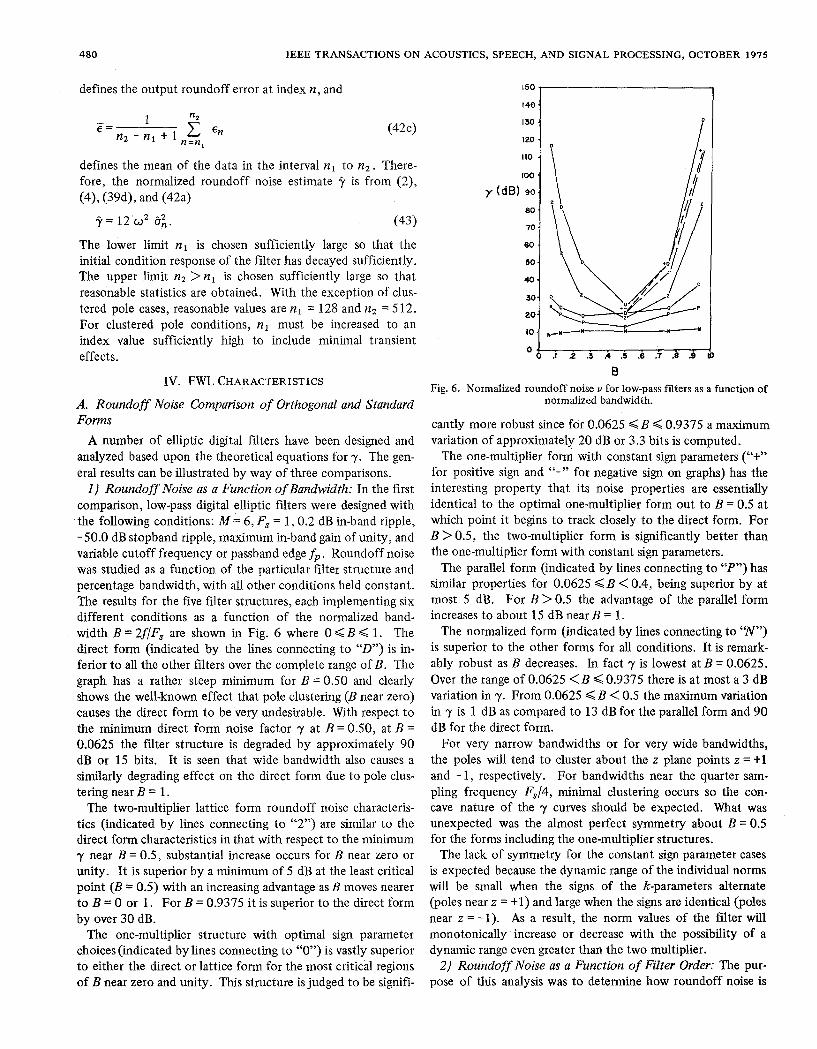
A number of elliptic digital filters have been designed and analyzed based upon the theoretical equations for y. The gen- eral results can be illustrated by way of three comparisons. 1) Roundoff Noise as a Function of Bandwidth: In the first
comparison, low-pass digital elliptic filters were designed with the following conditions: M = 6 , F, = 1,0.2 dB in-band ripple, -50.0 dB stopband ripple, maximum in-band gain of unity, and variable cutoff frequency or passband edge fp. Roundoff noise was studied as a function of the particular filter structure and percentage bandwidth, with all other conditions held constant. The results for the five filter structures, each implementing six different conditions as a function of the normalized band- width B = 2f/F, are shown in Fig. 6 where 0 < B < 1. The direct form (indicated by the lines connecting to “D”) is in- ferior to all the other filters over the complete range of B. The graph has a rather steep minimum for B = 0.50 and clearly shows the well-known effect that pole clustering (B near zero) causes the direct form to be very undesirable. With respect to the minimum direct form noise factor y at B = 0.50, at B = 0.0625 the filter structure is degraded by approximately 90 dB or 15 bits. It is seen that wide bandwidth also causes a similarly degrading effect on the direct form due to pole clus- tering near B = 1.
The two-multiplier lattice form roundoff noise characteris- tics (indicated by lines connecting to “2”) are similar to the direct form characteristics in that with respect to the minimum 7 near B = 0.5, substantial increase occurs for B near zero or unity. It is superior by a minimum of 5 dB at the least critical point (B = 0.5) with an increasing advantage as B moves nearer to B = 0 or 1. For B = 0.9375 it is superior to the direct form by over 30 dB.
The one-multiplier structure with optimal sign parameter choices (indicated by lines connecting to “0” ) is vastly superior to either the direct or lattice form for the most critical regions of B near zero and unity. This structure is judged to be signifi-
150
140.
-
130.
100 . 110 .
120 .
(dB) 90. 80.
70 ‘
60 . 50 .
40-
30.
20.
10.
O 6 .I .2 .s .i .s .6 .7 .e .B B
Fig. 6 . Normalized roundoff noise v for low-pass filters as a function of normalized bandwidth.
cantly more robust since for 0.0625 < B < 0.9375 a maximum variation of approximately 20 dB or 3.3 bits is computed.
The one-multiplier form with constant sign parameters (“+” for positive sign and “-” for negative sign on graphs) has the interesting property that its noise properties are essentially identical to the optimal one-multiplier form out to B = 0.5 at which point it begins to track closely to the direct form. For B > 0.5, the two-multiplier form is significantly better than the one-multiplier form with constant sign parameters.
The parallel form (indicated by lines connecting to “P”) has similar properties for 0.0625 < B < 0.4, being superior by at most 5 dB. For B > 0.5 the advantage of the parallel form increases to about 15 dB near B = 1.
The normalized form (indicated by lines connecting to “N”) is superior to the other forms for all conditions. It is remark- ably robust as B decreases. In fact 7 is lowest at B = 0.0625. Over the range of 0.0625 < B < 0.9375 there is at most a 3 dB variation in y. From 0.0625 < B < 0.5 the maximum variation in y is 1 dB as compared to 13 dB for the parallel form and 90 dB for the direct form.
For very narrow bandwidths or for very wide bandwidths, the poles will tend to cluster about the z plane points z = +1 and - 1, respectively. For bandwidths near the quarter sam- pling frequency F,/4, minimal clustering occurs so the con- cave nature of the y curves should be expected. What was unexpected was the almost perfect symmetry about B = 0.5 for the forms including the one-multiplier structures.
The lack of symmetry for the constant sign parameter cases is expected because the dynamic range of the individual norms will be small when the signs of the k-parameters alternate (poles near z = +1) and large when the signs are identical (poles near z = - 1). As a result, the norm values of the filter will monotonically increase or decrease with the possibility of a dynamic range even greater than the two multiplier.
2) Roundoff Noise as a Function of Filter Order: The pur- pose of this analysis was to determine how roundoff noise is

MARKEL AND GRAY: ROUNDOFF NOISE CHARACTERISTICS
affected by increasing the order of a particular low-pass fdter design, with all other parameters held constant. The condi- tions were: passband ripple = 0.2 dB, sampling frequency F, = 1.0, passband edge fp = 0.1, stopband edge f, = 0.105, and maximum in-band gain of unity. As M is increased, the stop- band attenuation is increased substantially, as governed by the elliptic filter design equations [SI. For example, askfincreases from 2 to 10 the stopband attenuation increases from 0.696 to 76.96 dB. The results are shown in Fig. 7.
The roundoff noise for the direct form is again worse than that of all other structures. The two-multiplier form results in about the same roundoff noise as the direct form for a filter design of two orders higher. The optimal sign choice for the one-multiplier form shows only a moderate increase in roundoff noise as M is increased. The constant sign param- eter forms are shown to generate substantially more noise than the optimal form for M > 6. , The parallel and normalized forms appear to have very similar noise characteristics for this example with the normalized form being superior by about 5 dB.
3) Bandpass Filter Analysis: The third comparison was based upon the design of bandpass filters with varying center fre- quencies. The purpose was to see whether any substantially different roundoff noise characteristics occur with respect to the low-pass filter designs. The bandpass filter parameters are as follows: M = 12, passband ripple = 0.2 dB, sampling fre- quency F, = 1 , stopband attenuation of - 50 dB, bandwidth = 0.05 with. variable center frequency fo (based upon the arith- metic mean) and maximum in-band gain of unity.
The theoretical noise calculations for the 42 different filters are summarized in Fig. 8. The results are consistent with the low-pass filter comparisons in the sense that the direct form is inferior to the two-multiplier form which in turn is inferior to the optimal one-multiplier structure.
The normalized form and the parallel form are essentially equivalent in noise characteristics for this bandpass case. The most striking difference between the bandpass and low-pass analysis is that whereas a maximum variation of 15 dB exists between the different structures in the low-pass case, near B = 0.5, an 84 dB difference exists in the bandpass case. All forms with the exception of the constant parameter one-multiplier forms have perfectly symmetric noise characteristics aboutf, = 0.5. In contrast to the low-pass case, the roundoff noise for the constant parameter one-multiplier implementation of the bandpass filters monotonically increases with increasing center frequency.
For bandpass filters the roundoff noise symmetry is theoreti- cally predictable for all but the one-multiplier forms since re- placing z by -2 in any filter simply reflects the effect about FsJ4 in the frequency domain. In terms of the k-parameters and tap parameters, replacing2 by -z effects only a sign change in the even subscript k-parameters. The tap parameters remain unchanged. The noise analysis results thus remain unchanged for the two-multiplier and normalized form. The one- multiplier form with constant sign parameter follows the same pattern as for the low-pass filters. If optimal sign param- eters are used the results are again symmetric since changes in
100
80
y(d8) 60
40
20
0
48 1
M Fig. 7. Normalized roundoff noise v as a function of filter order.
200 I I I I I
0‘ I I I I 1
Fo 0 0.2 0.4 0.6 0.0 1.0
Fig. 8. Normalized roundoff noise v for bandpass fdters as a function of normalized center frequency F,.
the signs of the k-parameters are compensated for by simply changing the sign parameters.
B. Clustered Pole Implementations In the previous section, it was shown that for the five fdter
structures studied, varying degrees of increasing roundoff noise are predicted as the bandwidth of the low-pass filters either de- creased or increased close to the half sampling frequency. In this section, theoretical and experimental results are presented in more detail for specific narrow bandwidth or clustered pole pair filters.
1) Narrow-Band Low-Pass Filter Implementation: As the bandwidth of a low-pass or high-pass filter is decreased, the poles tend to cluster near the points 1 + j0 or - 1 + j0, respec- tively in the z plane. The denominator of the direct form is then expected to have, coefficients close to the binomial coefficients
(44)
482 IEEE TRANSACTIONS ON ACOUSTICS, SPEECH, AND SIGNAL PROCESSING, OCTOBER 1975
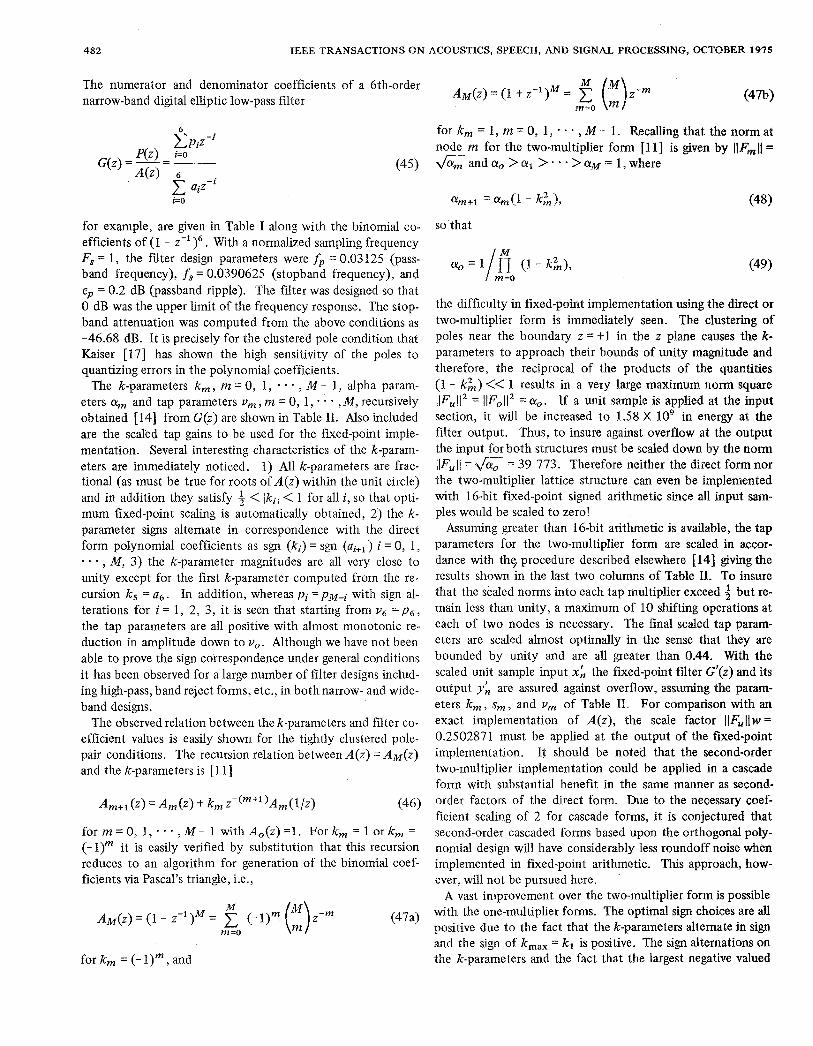
The numerator and denominator coefficients of a 6th-order narrow-band digital elliptic low-pass filter
i= 0
for example, are given in Table I along with the binomial co- efficients of (1 - With a normalized sampling frequency F, = 1, the filter design parameters were fp = 0.03125 (pass- band frequency), f, = 0.0390625 (stopband frequency), and ep = 0.2 dB (passband ripple). The filter was designed so that 0 dB was the upper limit of the frequency response. The stop- band attenuation was computed from the above conditions as -46.68 dB. It is precisely for the clustered pole condition that Kaiser [17] has shown the high sensitivity of the poles to quantizing errors in the polynomial coefficients.
The k-parameters k,, m = 0 , I , - , M - 1, alpha param- eters a, and tap parameters v, , m = 0, 1, * * , M , recursively obtained [ 141 from, G(z) are shown in Table 11. Also included are the scaled tap gains to be used for the fixed-point imple- mentation. Several interesting characteristics of the k-param- eters are immediately noticed. 1) All k-parameters are frac- tional (as must be true for roots of A ( z ) within the unit circle) and in addition they satisfy 4 < IkiI < 1 for all i, so that opti- mum fixed-point scaling is automatically obtained, 2) the k- parameter signs alternate in correspondence with the direct form polynomial coefficients as sgn (ki) = sgn (ai+l) i = 0 , 1, * * . , M , 3) the k-parameter magnitudes are all very close to unity except for the first k-parameter computed from the re- cursion k5 = a6. In addition, whereas pi = pM+ with sign al- terations for i = l , 2, 3, it is seen that starting from = p s , the tap parameters are all positive with almost monotonic re- duction in amplitude down to v,. Although we have not been able to prove the sign correspondence under general conditions it has been observed for a large number of filter designs includ- ing high-pass, band reject forms, etc., in both narrow- and wide- band designs.
The observed relation between the k-parameters and filter co- efficient values is easily shown for the tightly clustered pole- pair conditions. The recursion relation between A(z) = A"(z) and the k-parameters is [ 111
A~+l(z)=A,(z)+k,z-(m~l)A,(l/z) (46)
f o r m = O , l ; . . , M - l w i t h A , ( z ) = l . F o r k , = l o r k , = (- I), it is easily verified by substitution that this recursion reduces to an algorithm for generation of the binomial coef- ficients via Pascal's triangle, i.e.,
for k , = (- I)", and
A&f(Z) = (1 t z - y = m-0
for k, = 1, m = 0, 1, * , M - 1. Recalling that the norm at node m for the two-multiplier form [11] is given by l l F m l ~ = G a n d a , >orl > . * * > a ~ = 1,where
so that
(49)
the difficulty in fixed-point implementation using the direct or two-multiplier form is immediately seen. The clustering of poles near the boundary z = t1 in the z plane causes the k- parameters to approach their bounds of unity magnitude and therefore, the reciprocal of the products of the quantities (1 - k;) << 1 results in a very large maximum norm square ~ ~ F U ~ ~ ' = llFo112 = or,. If a unit sample i s applied at the input section, it will be increased to 1.58 X in energy at the filter output. Thus, to insure against overflow at the output the input for both structures must be scaled down by the norm l~FU~l = = 39 773. Therefore neither the direct form nor the two-multiplier lattice structure can even be implemented with 16-bit fixed-point signed arithmetic since all input sam- ples would be scaled to zero!
Assuming greater than 1Qbit arithmetic is available, the tap parameters for the two-multiplier form are scaled in accor- dance with the, procedure described elsewhere [14] giving the results shown in the last two columns of Table 11. To insure that the scaled norms into each tap multiplier exceed 3 but re- main less than unity, a maximum of 10 shifting operations at each of two nodes is necessary. The final scaled tap param- eters are scaled almost optimally in the sense that they are bounded by unity and are all greater than 0.44. With the scaled unit sample input x; the fixed-point filter G'(z) and its output y; are assured against overflow, assuming the param- eters k,, s,, and v, of Table 11. For comparison with an exact implementation of A(z) , the scale factor IIFullw = 0.2502871 must be applied at the output of the fixed-point implementation. It should be noted that the second-order two-multiplier implementation could be applied in a cascade form with substantial benefit in the same manner as second- order factors of the direct form. Due to the necessary coef- ficient scaling of 2 for cascade forms, it is conjectured that second-order cascaded forms based upon the orthogonal poly- nomial design will have considerably less roundoff noise when implemented in fixed-point arithmetic. This approach, how- ever, will not be pursued here. '
A vast improvement over the two-multiplier form is possible with the one-multiplier forms. The optimal sign choices are all positive due to the fact that the k-parameters alternate in sign and the sign of k,,, = kl is positive. The sign alternations on the k-parameters and the fact that the largest negative valued
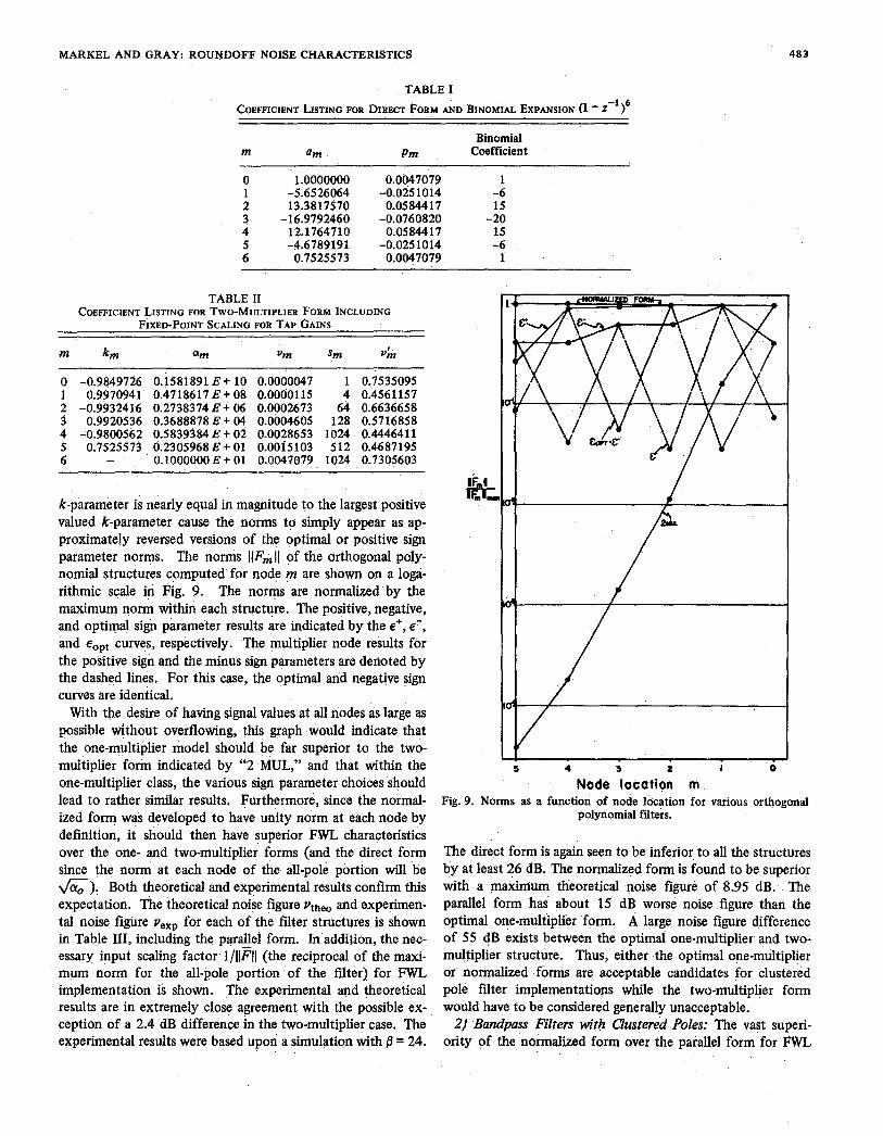
MARKEL AND GRAY: ROUNDOFF NOISE CHARACTERISTICS
TABLE I COEFFICIENT LISTING FOR DIRECT FORM AND BINOMIAL EXPANSION (1 - Z-’l6
Binomial m am Pm Coefficient
483
0 1.0000000 0.0047079 1
2 13.3817570 0.05 844 17 15 3 -16.9792460- -0.0760820 4 12.1764710 0.0584417
-20 15
5 -4.6789191 -0.0251014 6 0.7525573 0.0047079
-6 1
1 -5.6526064 -0.0251014 -6
TABLE I1 COEFFICIENT LISTING FOR TWO-MULTIPLIER FORM INCLUDING
FIXED-POINT SCALING FOR TAP GAINS
m km am Vm Sm vm
0 -0.9849726 0.1581891 E + 10 0.0000047 1 0.7535095 1 0.9970941 0.4718617B+ 08 0.0000115 4 0.4561157
3 0.9920536 0.3688878 E + 04 0.0004605 128 0.5716858
5 0.7525573 0.2305968 E + 01 O.OOi5103 512 0.4687195 6
2 -0.9932416 0.2738374 E + 06 0.0002673 64 0.6636658
4 -0.9800562 0.5839384 E t 02 0.0028653 1024 0.4446411
- 0.1000000 E + 01 0.0047079 1024 0.7305603
k-parameter is nearly equal in magnitude to the largest positive valued k-parameter cause the norms to simply appear as ap- proximately reversed versions of the optimal or positive sign parameter norms. The norms llF,II of the orthogonal poly- nomial structures computed for node m are shown on a loga- rithmic scale iri Fig. 9. The norms are normalized by the maximum norm within each structure. The positive, negative, and optimal sign parameter results are indicated by the E+, e-, and eopt curves, respectively. The multiplier node results for the positive sign and the minus sign parameters are denoted by the dashed lines. For this case, the optimal and negative sign curves are identical.
With the desire of having signal values at all nodes as large as possible without overflowing, this graph would indicate that the one-multiplier model should be far superior to the two- multiplier form indicated by “2 MUL,” and that within the one-multiplier class, the various sign parameter choices should lead to rather similar results. Furthermore, since the normal- ized form was developed to have unity norm at each node by definition, it should then have superior FWL characteristics over the one- and two-multiplier forms (and the direct form since the norm at each node of the all-pole portion will be 6). Both theoretical and experimentil results confirm this expectation. The theoretical noise figure Vtheo and experimen- tal noise figure veXp for each of the filter structures is shown in Table 111, including the parallel form. In addition, the nec- essary input scaling factor l/llFll (the reciprocal of the maxi- mum norm for the all-pole portion of the filter) for FWL implementation is shown. The experimental and theoretical results are in extremely close agreement with the possible ex- ception of a 2.4 dB difference h the two-multiplier case. The experimental results were based upon a simulation with p = 24.
5 4 3 L I 0
Node location m Fig. 9. Norms as a function of node location for various orthogonal
polynomial fiters.
The direct form is again seen to be inferior to all the structures by at least 26 dB. The normalized form is found to be superior with a m k m u m theoretical noise figure of 8.95 dB. The parallel form hai about 15 dB worse noise figure than the optimal one-multiplier form. A large noise figure difference of 55 dB exists between the optimai one-multiplier and two- multiplier structure. Thus, either the optimal one-multiplier or normalized forms are acceptable candidates for clustered pole filter implementations while the two-multiplier form would have to be considered generally unacceptable.
2) Bandpass Filters with Clustered Poles: The vast superi- ority of the normalized form over the parallel form for FWL

484 IEEE TRANSACTIONS ON ACOUSTICS, SPEECH, AND SIGNAL PROCESSING, OCTOBER 1975
TABLE I11 THEORETICAL AND EXPERIMENTAL ROUNDOFF NOISE CALCULATIONS FOR
CLUSTERED POLE EXAMPLE
Structure vthe0 (Decibels) vexp (Decibels) l/llFll
Direct form 112.19 11 1.53 2.531 10;: Two Mult. 85.68 83.25 One Mult. (Opt.) 30.12 30.13 1.4818 lo-'
2.531 10
Parallel 24.17 24.47 4.076 Normalized 8.95 8.6 1 1.000
implementation of filters with highly clustered poles is illus- trated in this section by way of several bandpass filter exam- ples. A series of eight 12th-order digital elliptic bandpass fil- ters were designed. and implemented ih both parallel and normalized structures. The design parameters were 0.2 dB passband ripple, maximum gain of 0 dB, stopband attenuation of -50 dB, bandwidth of 50 Hz, sampling frequency of 10 kHz, and center frequency fo(kHz) = 0.51 f 0.75, I = 1,2, - * , 6.
These filters present extremely difficult implementation characteristics. For example, the log-magnitude spectrum of the 1 = 1 'case filter unit sample response is shown in Fig. 10. Viewed over the total 5-kHz range, the fdter response appears to be almost an impulse in frequency with a base line at -50 dB (the lack of ripples in the stopband is due to the limited frequency domain resolution). The double-precision direct fork coefficients are presented along with the k-parameters, tap parameters, and alpha parameters (norm-squared values for the two-multiplier lattice form) in Table IV. The direct form scaling norm for this filter is the rather enormous value 6 = 0.649 X lo9. The k-parameters are seen to alternate between -0.7 and. 1 .O - e where e is a very small positive number. This property is based upon the poles of l/A(z) having nearly identical values.
A, theoretical noise figure comparison for each of the six parallel and normalized structures is presented in Fig. 1 1. The significant advantage of the normalized form for the case of highly clustered poles is clearly shown. The noise figure is nearly constant versus frequency at 12 dB over the total fre- quency .range shown. The parallel form, under clustered pole conditions tends to show similar characteristics to the two- multiplier and the direct form, namely, monotonic increases in 7 to the right and left o f f = FJ4, as illustrated in previous sections. For the I = 1 case, the normalized form is superior to the parallel form by approximately 61 dB or 10 bits.
CONCLUSIONS The roundoff noise characteristics of three structures de-
veloped from the theory of orthogonal polynomials have been presented in this paper. These structures are referred to as a two-multiplier, one-multiplier, and normalized form. A com- plete theoretical roundoff noise analysis of the filters, when scaled for fixed-point implementation, was presented along with experimental results which verify the theory. The or- thogonal polynomial structures were compared to two .stan- dard structures, the direct and parallel form.
0
-20
-40
dB -60
-80
-100 0 1.0 2.0 3.0 4.0 5.0
f ( k H z ) Fig. 10. Frequency response of case I = 1.
The theoretical noise analysis was developed in terms of re- cursive relations based upon orthogonal polynomial properties and Mason's flow graph theory.
It can generally be stated that the direct form is inferior to all the other structures studied. The two-multiplier lattice form (having two multiplications and two additions per sec- tion) has similar properties to the direct form, only its round- off noise is smaller. The lattice form degrades badly in clus- tered pole conditions. The optimal one-multiplier form (having one multiplication and three additions' per section) appears to match more closely the characteristics of the paral- lel form over a number of different conditions with generally larger roundoff noise.
The third, the normalized structure (having four multiplica- tions and two additions per section), appears to have remark- ably robust roundoff noise characteristics. For moderately clustered pole-pair filters, the normalized and parallel forms seem to have similar characteristics, with the normalized form having lower overall roundoff noise. For tightly clustered conditions, the normalized form is vastly superior t o the paral- lel form. Even though this structure appears to be computa- tionally expensive, each stage can be shown to be precisely implemented as a single complex multiplication [13] , an elementary operation on some signal processing machines.
There are several modifications and extensions possible to the results presented here. For example, considerably better roundoff noise results for the one-multiplier and two-multiplier forms are possible by simply inserting binary shifts (scaling by powers of two) between adjacent sections. Since the norms at the nodes are h o w n [ 111 , scaling factors can be computed to increase the norms toward unity, thus improving roundoff

MARKEL AND GRAY: ROUNDOFF NOISE CHARACTERISTICS 485
80
60
40
y (dB)
20
n
TABLE IV PARAMETER LISTINGS FOR CLUSTERED POLE BANDPASS FILTER EXAMPLE
i ai P i
0 1 2 3 4 5 6 7 8 9
10 11 12
0.10000 00000 00000 D + 01
0.35725 53888 44417 D + 02
0.19203 68436 25898 D + 03
0.32056 44430 01992 D + 03
0.18914 25233 22361 D + 03
0.34656 76009 84371 D + 02
0.95546 29607 88787 D + 00
-0.84529 $1876 65357 D + 01
-0.97864 35972 54877 D + 02
-0.28303 37826 85337 D + 03
-0.28089 27896 66911 D + 03
-0.95560 23916 98399 D + 02
-0.81380 40444 81358 D + 01
0.31086 20533 01988 D - 02 -0.26333 92951 75400 D - 01
0.11156 90817 82533 D + 00
0.60318 74426 87684 D + 00
0.10139 44793 16550 D + 01
0.60318 74426 87684 D + 00
0.11156 90817 82533 D + 00
-0.30646 12979 58780 D + 00
-0.89197 99578 96173 D + 00
-0.89197 99578 96173 D + 00
-0.30646 12979 58780 D + 00
-0.26333 92951 75399 D - 01 0.31086 20533 01988 D - 02
m km-t Vm am
0 1 2 3 4 5 6 7 8 9
10 11 12
-0.70906 26919 71048 D + 00 -
0.99964 94678 57360 D + 00
0.99991 43518 50219 D + 00
0.99982 85102 22952 D + 00
-0.70584 79764 44104 D + 00
-0.70705 58761 09997 D + 00
-0.70709 16745 51414 D + 00 -0.99979 51230 16348 D + 00 -0.70727 02736 87968 D + 00
0.99948 26156 85041 D + 00
0.95546 29607 88787 D + 00 -0.70682 79059 12227 D + 00
0.92464 66030 01427 D - 13 0.19212 15222 30053 D - 10
-0.33950 52108 81388 D - 10 -0.11952 34062 40397 D - 09 -0.42857 86472 68260 D - 07
0.21688 25105 11948 D - 09 0.16884 23952 63443 D - 06
-0.12769 23129 00162 D - 07 -0.17590 85835 99515 D - 06 -0.40979 60836 44792 D - 04
0.69316 56096 68874 D - 04 -0.56909 74914 57393 D - 04
0.31086 20533 01988 D - 02
0.42170 E + 20 0.20968 E + 20 0.14698 E + 17 0.73749 E + 16 0.12632 E + 13 0.63171 E + 12 0.21665 E + 09 0.10833 E + 09 0.44383 E + 05 0.22181 E + 05 0.22947 E + 02 0.1 1482 E + 02 0.10000 E + 01
I I I I
i 0 I .o 2.0 3.0 4.0 5.0
F, (kHz) Fig. 11. Normalized roundoff noise v as a function of center
frequency F,.
noise characteristics. The direct filter form could also be implemented in a modified cascade or parallel form where the individual sections are implemented as orthogonal polynomial filter sections. The roundoff noise properties of these alter- nate forms have not been studied.
REFERENCES [ 11 L. B. Jackson, “An analysis of roundoff noise in digital filters,”
boken, N.J., 1969. Sc.D. dissertation, Dep. Elec. Eng., Stevens Inst. Technol., HO-
[ 21 -, “On the interaction of roundoff noise and dynamic range in digital fiters,”Bell Syst. Tech. J . , vol. 49, pp. 158-184, 1970.
[3] -, “Roundoff-noise analysis for fixed-point digital fiiters real- ized in cascade or parallel form,” IEEE Trans. Audio Electro- acoust. (Special Issue on Digital Filtering), vol. AU-18, pp. 107- 122, June 1970.
141 A. V. Oppenheim and C. J. Weinstein, “Effects of finite register length in digital filtering and the fast Fourier transform,” h o c .
[5] B. Gold and C. M. Rader, Digital Processing of Signals. New York: McGraw-Hill, 1969.
[6] J. L. Kelly, Jr. and C. Lochbaum, “Speech synthesiS,” in Proc. Stockholm Speech Communications Seminar, R.I.T., Stockholm, Sweden, Sept. 1962.
[7] F. Itakura and S. Saito, “Digital filtering techniques for speech analysis and synthesis.,” presented at the 7th Int. Congr. Acoust., Paper 2SC-1, Budapest, Hungary, 1971.
[ 81 A. Fettweis, “Some principles of designing digital fiiters imitating classical filter structures,” IEEE Trans. Circuit Theory (Corresp.),
[9] S . K. Mitra and R. J. Sherwood, “Canonic realizations of digital fiiters using the continued fraction expansion,” IEEE Trans. Au- dio Electroacoust., vol. AU-20, pp. 185-194, Aug. 1972.
[ 101 -, “Digital ladder networks,” IEEE Trans. Audio Electroacoust., vol. AU-21, pp. 30-36, Feb. 1973.
[ 11 J A. H. Gray, Jr. and J. D. Markel, “Digital lattice and ladder fii- ter synthesis,” IEEE Trans. Audio Electroacoust., vol. AU-21, pp. 491-500, Dec. 1973.
[ 121 R. Crochiere, “Digital ladder fiiter structures and coefficient sensitivity,” Res. Lab. Electron., Mass. Inst. Technol., Cam- bridge,.Rep. 103, Oct. 15, 1971.
[13] A. H. Gray, Jr. and J. D. Markel, “A normalized digital fiitei structure,” IEEE Trans. Acoust., Speech, Signal Processing (Spe- cial Issue on I 9 74 Arden House Workshop on Digital Signal Pro- cessing), vol. ASSP-23, pp. 268-277, June 1975.
IEEE,vol. 60, pp. 951-976, Aug. 1972.
V O ~ . CT-18,pp. 314-316, Mar. 1971.
486 IEEE TRANSACTIONS ON ACOUSTICS, SPEECH, AND SIGNAL PROCESSING, VOL. ASSP-23, NO. 5 , OCTOBER 1975
[ 141 J. D. Markel and A. H. Gray, Jr., “Fixed-point implementation [ 161 -, “Feedback theory-further properties of signal flow graphs,” algorithms for a class of orthogonal polynomial filter structures,” P~oc. IRE, V O ~ . 44, pp. 920-926, July 1956. this issue, pp. 486-494. [ 171 J. F. Kaiser, “Some practical considerations in the realization of
[15] S . J. Mason, “Feedback theory: Some properties of signal flow linear digital filters,” in Proc. 3rd Allerton Con$ Circuit and graphs,”Proc, IRE, vol. 41, pp. 1144-1156, Sept. 1953. Systems Theory, pp. 621-633,1965.
Fixed-point Implementation Algorithms for a Class of Orthogonal Polynomial Filter Structures
JOHN D. MARKEL, MEMBER, IEEE, AND AUGUSTINE H. GRAY, JR., MEMBER, IEEE
Abstract-In previous papers it has been demonskated that a class of digital fiiter structures derived from the theory of orthogonal poly- nomials has practical utility in digital signal processing problems. In t h i s paper the specific algorithms necessary to synthesize and scale these structures in fixed-point arithmetic (based upon L2 norm scaling) are presented and implemented as Fortran programs.
I I. INTRODUCTION
T has been shown recently that a new class of digital filter structures based upon a theory of orthogonal polynomials has important properties relevant to a nymber of signal pro-
cessing problems. These structures are completely general in the sense that any direct form can be transformed into any of the orthogonal polynomial structures [ 11 -[3] .
Important applications of these structures are in 1) linear prediction speech analysislsynthesis where the filter coef- ficients most desirable for transmission are precisely those used for implementing the filter, 2) general or special purpose computer implementation where high accuracy must be main- tained with limited fured-point word lengths, and 3) in one form, for implementing clustered pole filters.
The “two-multiplier structure” is obtained recursively from a direct form rational structure. It has been shown to have similar characteristics to the direct form but always with superior roundoff noise characteristics. A “one-multiplier” structure is obtained by generalizing the “two-multiplier” equations and then performing a simple substitution. The resultant filter is canonic in multipliers and delays and in one form (referred to as the ‘‘optimal one-multiplier structure”) has generally much improved noise characteristics over the
Manuscript.received August 2, 1974; revised March 28,1975. This re- search was supported by the Advanced Research Projects Agency of the Department of Defense and was monitored by the Office of Naval Re- search under Contract N00014-73C-0221.
J. D. Markel is with the Speech Communications Research Labora- tory, Inc., Santa Barbara, Calif. 93109.
A. H. Gray, Jr. is with the Speech Communications Research Labora- tory, Inc., Santa Barbara, Calif. 93109 and the Department of Electrical Engineering, and Computer Science, University of California, Santa Barbara, Calif. 93106.
“two-multiplier.’’ A further transformation has resulted in an orthonormal polynomial form referred to as the “normalized structure.” This structure has been shown to be superior in its roundoff noise characteristics (for both rounding and trunca- tion arithmetic) to any of the other orthogonal polynomial forms or the direct, or parallel, form. In fact, its superiority increases as the poles of the filter become more clustered (the situation in which all other forms are severely degraded).
Due to the relatively new introduction of these structures [l] , [2] and their possible appearance of complexity, it is believed that algorithms for implementing these structures starting from the standard direct form would be quite useful for those interested in either studying properties of the filters or implementing particular filters on a computer with fNed- point arithmetic. The structures to be presented are designed very efficiently. As long as the direct form is stable with single precision floating-point arithmetic, no double precision opera- tions are necessary. All parameters are automatically scaled to a fractional format with a final (possibly nonfractional) output gain factor for referencing the results to an exact implementa- tion. Computer programs based upon the algorithms will be given along with several examples of the programs.
11. ALGORITHMS A, Direct to Two-Multiplier Lattice Structure
The direct form filter is defined by
w = PIM(Z)/4&) where
m Pm(z)= x P m , i Z - ’
i=O
and
Am(z) = x am, z - ~ m
i=O
with am, = 1. If