r&s vse-k6 pulse user manual - rohde & schwarz of remote commands (pulse).....337...
TRANSCRIPT

R&S®VSE-K6Pulse Measurement ApplicationUser Manual
User
Man
ual
1176.8922.02 ─ 04(;ÚçF2)

This manual applies to the R&S®VSE base software (1320.7500.xx / 1320.7951.xx) version 1.30 and later.The following firmware options are described:● R&S VSE-K6 (1320.7516.02)
© 2017 Rohde & Schwarz GmbH & Co. KGMühldorfstr. 15, 81671 München, GermanyPhone: +49 89 41 29 - 0Fax: +49 89 41 29 12 164Email: [email protected]: www.rohde-schwarz.comSubject to change – Data without tolerance limits is not binding.R&S® is a registered trademark of Rohde & Schwarz GmbH & Co. KG.Trade names are trademarks of their owners.
The following abbreviations are used throughout this manual: R&S®VSE is abbreviated as R&S VSE.

ContentsR&S®VSE-K6
3User Manual 1176.8922.02 ─ 04
Contents1 Preface.................................................................................................... 5
1.1 About this Manual......................................................................................................... 5
1.2 Typographical Conventions.........................................................................................5
2 Welcome to the Pulse Measurements Application............................. 72.1 Starting the Pulse Application..................................................................................... 7
2.2 Understanding the Display Information......................................................................8
3 Measurements and Result Displays...................................................113.1 Pulse Parameters........................................................................................................ 11
3.2 Evaluation Methods for Pulse Measurements..........................................................25
4 Measurement Basics........................................................................... 364.1 Parameter Definitions................................................................................................. 36
4.2 Pulse Detection........................................................................................................... 39
4.3 Parameter Spectrum Calculation...............................................................................41
4.4 Trace Evaluation......................................................................................................... 44
5 Configuration........................................................................................505.1 Configuration Overview..............................................................................................50
5.2 Signal Description.......................................................................................................52
5.3 Input Source Settings................................................................................................. 54
5.4 Frontend Settings....................................................................................................... 60
5.5 Trigger Settings...........................................................................................................64
5.6 Data Acquisition..........................................................................................................68
5.7 Pulse Detection........................................................................................................... 70
5.8 Pulse Measurement Settings..................................................................................... 71
5.9 Automatic Settings..................................................................................................... 77
6 Analysis................................................................................................ 786.1 Result Configuration...................................................................................................78
6.2 Markers........................................................................................................................ 95
6.3 Trace Configuration.................................................................................................. 103
7 How to Perform Measurements in the Pulse Application.............. 109

ContentsR&S®VSE-K6
4User Manual 1176.8922.02 ─ 04
7.1 How to Perform a Standard Pulse Measurement................................................... 109
7.2 How to Configure a Limit Check for a Pulse Measurement.................................. 110
8 Remote Commands for Pulse Measurements.................................1128.1 Introduction............................................................................................................... 112
8.2 Common Suffixes......................................................................................................117
8.3 Activating Pulse Measurements.............................................................................. 117
8.4 Configuring the Measurement................................................................................. 118
8.5 Analyzing Results..................................................................................................... 235
8.6 Retrieving Results.....................................................................................................252
8.7 Programming Example: Pulse Measurement......................................................... 319
Annex.................................................................................................. 324
A Menu Reference................................................................................. 325A.1 Common R&S VSE Menus....................................................................................... 325
A.2 Pulse Measurements Menus.................................................................................... 327
B Reference of Toolbar Functions.......................................................330
C Reference: ASCII File Export Format............................................... 334
D Effects of Large Gauss Filters.......................................................... 336
List of Remote Commands (Pulse)...................................................337
Index....................................................................................................353

PrefaceR&S®VSE-K6
5User Manual 1176.8922.02 ─ 04
1 Preface
1.1 About this Manual
This R&S VSE Pulse User Manual provides all the information specific to the applica-tion. All general software functions and settings common to all applications and oper-ating modes are described in the R&S VSE Base Software User Manual.
The main focus in this manual is on the measurement results and the tasks required toobtain them. The following topics are included:
● Welcome to the R&S VSE Pulse applicationIntroduction to and getting familiar with the application
● Measurements and Result DisplaysDetails on supported measurements and their result types
● Measurement BasicsBackground information on basic terms and principles in the context of the mea-surement
● Configuration + AnalysisA concise description of all functions and settings available to configure measure-ments and analyze results with their corresponding remote control command
● Data ExportDescription of general functions to export measurement data
● How to Perform Measurements in the R&S VSE Pulse applicationThe basic procedure to perform each measurement and step-by-step instructionsfor more complex tasks or alternative methods
● Optimizing and Troubleshooting the MeasurementHints and tips on how to handle errors and optimize the measurement configura-tion
● Remote Commands for R&S VSE Pulse application MeasurementsRemote commands required to configure and perform R&S VSE Pulse applicationmeasurements in a remote environment, sorted by tasks(Commands required to set up the environment or to perform common tasks in thesoftware are provided in the R&S VSE Base Software User Manual)Programming examples demonstrate the use of many commands and can usuallybe executed directly for test purposes
● List of remote commandsAlphabetical list of all remote commands described in the manual
● Index
1.2 Typographical Conventions
The following text markers are used throughout this documentation:
Typographical Conventions

PrefaceR&S®VSE-K6
6User Manual 1176.8922.02 ─ 04
Convention Description
"Graphical user interface ele-ments"
All names of graphical user interface elements on the screen, such asdialog boxes, menus, options, buttons, and softkeys are enclosed byquotation marks.
KEYS Key names are written in capital letters.
File names, commands,program code
File names, commands, coding samples and screen output are distin-guished by their font.
Input Input to be entered by the user is displayed in italics.
Links Links that you can click are displayed in blue font.
"References" References to other parts of the documentation are enclosed by quota-tion marks.
Typographical Conventions

Welcome to the Pulse Measurements ApplicationR&S®VSE-K6
7User Manual 1176.8922.02 ─ 04
2 Welcome to the Pulse Measurements Appli-cationThe R&S VSE-K6 is a firmware application that adds functionality to perform measure-ments on pulsed signals to the R&S VSE.
The R&S VSE Pulse application provides measurement and analysis functions forpulse signals frequently used in radar applications, for example.
The R&S VSE Pulse application features:● Measurement of basic pulse characteristics● Analysis of parameter trends over time● Display of amplitude, frequency and phase measurement traces for individual pul-
ses
This user manual contains a description of the functionality that the application pro-vides, including remote control operation.
Functions that are not discussed in this manual are the same as in the I/Q Analyzerapplication and are described in the R&S VSE Base Software User Manual. The latestversion is available for download at the product homepage (http://www.rohde-schwarz.com/product/VSE.html).
2.1 Starting the Pulse Application
Pulse measurements require a separate application on the R&S VSE. It is activated bycreating a new measurement channel in Pulse mode.
To activate the Pulse application
1.
Select the "Add Channel" function in the Sequence tool window.
A dialog box opens that contains all operating modes and applications currentlyavailable in your R&S VSE.
Starting the Pulse Application

Welcome to the Pulse Measurements ApplicationR&S®VSE-K6
8User Manual 1176.8922.02 ─ 04
2. Select the "Pulse" item.
The R&S VSE opens a new measurement channel for the R&S VSE Pulse applica-tion.
2.2 Understanding the Display Information
The following figure shows a measurement diagram during analyzer operation. All dif-ferent information areas are labeled. They are explained in more detail in the followingsections.
Understanding the Display Information

Welcome to the Pulse Measurements ApplicationR&S®VSE-K6
9User Manual 1176.8922.02 ─ 04
2
3
4
5
1
1 = Color coding for windows of same channel2 = Channel bar with measurement settings3 = Window title bar with diagram-specific (trace) information4 = Diagram area5 = Diagram footer with diagram-specific information, depending on result display
Channel bar information
In the Pulse application, the R&S VSE shows the following settings:
Table 2-1: Information displayed in the channel bar in the Pulse application
Ref Level Reference level
Att Mechanical and electronic RF attenuation (if available)
Freq Center frequency for the RF signal
Meas Time Measurement time (data acquisition time)
Meas BW Measurement bandwidth
SRate Sample rate
In addition, the channel bar also displays information on instrument settings that affectthe measurement results even though this is not immediately apparent from the displayof the measured values (e.g. transducer or trigger settings). This information is dis-played only when applicable for the current measurement. For details see theR&S VSE Base Software User Manual.
Window title bar information
For each diagram, the header provides the following information:
Understanding the Display Information

Welcome to the Pulse Measurements ApplicationR&S®VSE-K6
10User Manual 1176.8922.02 ─ 04
1 2 5 6 7
0
3 4
Figure 2-1: Window title bar information in the Pulse application
0 = Color coding for windows of same channel1 = Edit result display function2 = Channel name3 = Window number4 = Window type (+ pulse number for pulse-based displays)5 = Trace color, trace number, trace detector, trace mode6 = Dock/undock window function7 = Close window function
Diagram area
The diagram area displays the results according to the selected result displays (seeChapter 3.2, "Evaluation Methods for Pulse Measurements", on page 25).
Diagram footer information
The diagram footer (beneath the diagram) contains the start and stop values for thedisplayed time range.
Status bar information
The software status, errors and warnings and any irregularities in the software are indi-cated in the status bar at the bottom of the R&S VSE window.
Understanding the Display Information

Measurements and Result DisplaysR&S®VSE-K6
11User Manual 1176.8922.02 ─ 04
3 Measurements and Result DisplaysDuring a pulse measurement, I/Q data from the input signal is captured for a specifiedtime or for a specified record length. Pulses are detected from the signal according tospecified thresholds and user-defined criteria. The measured signal is then comparedwith the ideal signal described by the user and any deviations are recorded. Thedefined range of measured data is then evaluated to determine characteristic pulseparameters. These parameters can either be displayed as traces, in a table, or be eval-uated statistically over a series of measurements.
Measurement range vs result range
The measurement range defines which part of a pulse is measured (for example forfrequency deviation), whereas the result range determines which data is displayedon the screen in the form of amplitude, frequency or phase vs. time traces.
Result display windows
For each measurement, a separate measurement channel is activated. Each measure-ment channel can provide multiple result displays, which are displayed in individualwindows. The measurement windows can be rearranged and configured in theR&S VSE to meet your requirements. All windows that belong to the same measure-ment (including the channel bar) are indicated by a colored line at the top of the win-dow title bar.
► To add further result displays for the Pulse channel, select the "Add Window"icon from the toolbar, or select the "Window > New Window" menu item.
For details on working with channels and windows see the "Operating Basics"chapter in the R&S VSE Base Software User Manual.
● Pulse Parameters....................................................................................................11● Evaluation Methods for Pulse Measurements.........................................................25
3.1 Pulse Parameters
The pulse parameters to be measured are based primarily on the IEEE 181 Standard181-2003. For detailed descriptions refer to the standard documentation ("IEEE Stan-dard on Transitions, Pulses, and Related Waveforms", from the IEEE Instrumentationand Measurement (I&M) Society, 7 July 2003).
The following graphic illustrates the main pulse parameters and characteristic values.(For a definition of the values used to determine the measured pulse parameters seeChapter 4.1, "Parameter Definitions", on page 36.)
Pulse Parameters

Measurements and Result DisplaysR&S®VSE-K6
12User Manual 1176.8922.02 ─ 04
Figure 3-1: Definition of the main pulse parameters and characteristic values
In order to obtain these results, select the corresponding parameter in the result config-uration (see Chapter 6.1, "Result Configuration", on page 78) or apply the requiredSCPI parameter to the remote command (see Chapter 8.4.10, "Configuring theResults", on page 162 and Chapter 8.6.1, "Retrieving Results", on page 252).
● Timing Parameters..................................................................................................12● Power/Amplitude Parameters................................................................................. 15● Frequency Parameters............................................................................................18● Phase Parameters.................................................................................................. 20● Envelope Model (Cardinal Data Points) Parameters.............................................. 21
3.1.1 Timing Parameters
The following timing parameters can be determined by the R&S VSE Pulse application.
Timestamp.................................................................................................................... 13Settling Time................................................................................................................. 13Rise Time...................................................................................................................... 13Fall Time....................................................................................................................... 13Pulse Width (ON Time)................................................................................................. 14Off Time........................................................................................................................ 14
Pulse Parameters

Measurements and Result DisplaysR&S®VSE-K6
13User Manual 1176.8922.02 ─ 04
Duty Ratio..................................................................................................................... 14Duty Cycle (%).............................................................................................................. 14Pulse Repetition Interval............................................................................................... 14Pulse Repetition Frequency (Hz).................................................................................. 15
TimestampThe time stamp uniquely identifies each pulse in the capture buffer. It is defined as thetime from the capture start point to the beginning of the pulse period of the currentpulse. Depending on the user-specified definition of the pulse period, the period beginswith the mid-level crossing of the current pulse's rising edge (period: high-to-low) or themid-level crossing of the previous pulse's falling edge (period low-to-high). See also"Pulse Period" on page 53.
Remote command: [SENSe:]PULSe:TIMing:TSTamp? on page 283CALCulate<n>:TABLe:TIMing:TSTamp on page 227[SENSe:]PULSe:TIMing:TSTamp:LIMit? on page 313
Settling TimeThe difference between the time at which the pulse exceeds the mid threshold on therising edge to the point where the pulse waveform remains within the pulse boundary(ON Inner/ ON Outer)
See Figure 3-1
Remote command: [SENSe:]PULSe:TIMing:SETTling? on page 282CALCulate<n>:TABLe:TIMing:SETTling on page 226[SENSe:]PULSe:TIMing:SETTling:LIMit? on page 313
Rise TimeThe time required for the pulse to transition from the base to the top level. This is thedifference between the time at which the pulse exceeds the lower and upper thresh-olds.
See Figure 3-1
Remote command: [SENSe:]PULSe:TIMing:RISE? on page 281CALCulate<n>:TABLe:TIMing:RISE on page 226[SENSe:]PULSe:TIMing:RISE:LIMit? on page 313
Fall TimeThe time required for the pulse to transition from the top to the base level. This is thedifference between the time at which the pulse drops below the upper and lowerthresholds.
See Figure 3-1
Remote command: [SENSe:]PULSe:TIMing:FALL? on page 278CALCulate<n>:TABLe:TIMing:FALL on page 225[SENSe:]PULSe:TIMing:FALL:LIMit? on page 312
Pulse Parameters

Measurements and Result DisplaysR&S®VSE-K6
14User Manual 1176.8922.02 ─ 04
Pulse Width (ON Time)The time that the pulse remains at the top level ("ON"). This is the time between thefirst positive edge and the subsequent negative edge of the pulse in seconds, wherethe edges occur at crossings of the mid threshold.
See Figure 3-1
Remote command: [SENSe:]PULSe:TIMing:PWIDth? on page 281CALCulate<n>:TABLe:TIMing:PWIDth on page 226[SENSe:]PULSe:TIMing:PWIDth:LIMit? on page 313
Off TimeThe time that the pulse remains at the base level ("OFF"). This is the time between thefirst negative edge and the subsequent positive edge of the pulse in seconds, wherethe edges occur at crossings of the mid threshold.
See Figure 3-1
Remote command: [SENSe:]PULSe:TIMing:OFF? on page 278CALCulate<n>:TABLe:TIMing:OFF on page 225[SENSe:]PULSe:TIMing:OFF:LIMit? on page 312
Duty RatioThe ratio of the "Pulse Width" to "Pulse Repetition Interval" expressed as a valuebetween 0 and 1 (requires at least two measured pulses)
Remote command: [SENSe:]PULSe:TIMing:DRATio? on page 277CALCulate<n>:TABLe:TIMing:DRATio on page 225[SENSe:]PULSe:TIMing:DRATio:LIMit? on page 312
Duty Cycle (%)The ratio of the "Pulse Width" to "Pulse Repetition Interval" expressed as a percentage(requires at least two measured pulses)
Remote command: [SENSe:]PULSe:TIMing:DCYCle? on page 276CALCulate<n>:TABLe:TIMing:DCYCle on page 224[SENSe:]PULSe:TIMing:DCYCle:LIMit? on page 312
Pulse Repetition IntervalThe time between two consecutive edges of the same polarity in seconds (requires atleast two measured pulses). The user-specified definition of the pulse period(see"Pulse Period" on page 53) determines whether this value is calculated fromconsecutive rising or falling edges.
Remote command: [SENSe:]PULSe:TIMing:PRI? on page 280CALCulate<n>:TABLe:TIMing:PRI on page 226[SENSe:]PULSe:TIMing:PRI:LIMit? on page 312
Pulse Parameters

Measurements and Result DisplaysR&S®VSE-K6
15User Manual 1176.8922.02 ─ 04
Pulse Repetition Frequency (Hz)The frequency of occurrence of pulses, i.e. inverse of the "Pulse Repetition Interval"(requires at least two measured pulses)
Remote command: [SENSe:]PULSe:TIMing:PRF? on page 279CALCulate<n>:TABLe:TIMing:PRF on page 225[SENSe:]PULSe:TIMing:PRF:LIMit? on page 312
3.1.2 Power/Amplitude Parameters
The following power/amplitude parameters can be determined by the R&S VSE Pulseapplication.
Top Power.....................................................................................................................15Base Power...................................................................................................................15Pulse Amplitude............................................................................................................ 16In-Phase Amplitude/Quadrature Amplitude...................................................................16Average ON Power....................................................................................................... 16Average Tx Power.........................................................................................................16Minimum Power............................................................................................................ 16Peak Power...................................................................................................................16Peak-to-Avg ON Power Ratio....................................................................................... 17Peak-to-Average Tx Power Ratio..................................................................................17Peak-to-Min Power Ratio.............................................................................................. 17Droop............................................................................................................................ 17Ripple............................................................................................................................ 17Overshoot......................................................................................................................18Power (at Point)............................................................................................................ 18Pulse-to-Pulse Power Ratio.......................................................................................... 18
Top PowerThe median pulse ON power. The value of this parameter is used as a reference(100%) to determine other parameter values such as the rising / falling thresholds. Var-ious algorithms are provided to determine the top power (see "Measurement Algo-rithm" on page 73).
Remote command: [SENSe:]PULSe:POWer:TOP? on page 274CALCulate<n>:TABLe:POWer:TOP on page 224[SENSe:]PULSe:POWer:TOP:LIMit? on page 312
Base PowerThe median pulse OFF power. The value of this parameter is used as a reference (0%)to determine other parameter values such as the rising / falling thresholds.
Remote command: [SENSe:]PULSe:POWer:BASE? on page 264CALCulate<n>:TABLe:POWer:BASE on page 220[SENSe:]PULSe:POWer:BASE:LIMit? on page 312
Pulse Parameters

Measurements and Result DisplaysR&S®VSE-K6
16User Manual 1176.8922.02 ─ 04
Pulse AmplitudeThe difference between the "Top Power" and the "Base Power". This value determinesthe 100% power range (amplitude).
Remote command: [SENSe:]PULSe:POWer:AMPLitude? on page 261CALCulate<n>:TABLe:POWer:AMPLitude on page 219[SENSe:]PULSe:POWer:AMPLitude:LIMit? on page 312
In-Phase Amplitude/Quadrature AmplitudeThe pulse in-phase or quadrature amplitude as a voltage, measured at the measure-ment point of the pulse (see Chapter 5.8.2, "Measurement Point", on page 74). Val-ues range from -10 mV to +10 mV.
Remote command: Querying results:[SENSe:]PULSe:POWer:AMPLitude:I? on page 262[SENSe:]PULSe:POWer:AMPLitude:Q? on page 262Including results in result summary table:CALCulate<n>:TABLe:POWer:AMPLitude:I on page 219CALCulate<n>:TABLe:POWer:AMPLitude:Q on page 220Querying limit check results:[SENSe:]PULSe:POWer:AMPLitude:I:LIMit? on page 312[SENSe:]PULSe:POWer:AMPLitude:Q:LIMit? on page 312
Average ON PowerThe average power during the pulse ON time
Remote command: [SENSe:]PULSe:POWer:ON? on page 266CALCulate<n>:TABLe:POWer:ON on page 221[SENSe:]PULSe:POWer:ON:LIMit? on page 312
Average Tx PowerThe average transmission power over the entire pulse ON + OFF time
Remote command: [SENSe:]PULSe:POWer:AVG? on page 263CALCulate<n>:TABLe:POWer:AVG on page 220[SENSe:]PULSe:POWer:AVG:LIMit? on page 312
Minimum PowerThe minimum power over the entire pulse ON + OFF time
Remote command: [SENSe:]PULSe:POWer:MIN? on page 265CALCulate<n>:TABLe:POWer:MIN on page 221[SENSe:]PULSe:POWer:MIN:LIMit? on page 312
Peak PowerThe maximum power over the entire pulse ON + OFF time
Pulse Parameters

Measurements and Result DisplaysR&S®VSE-K6
17User Manual 1176.8922.02 ─ 04
Remote command: [SENSe:]PULSe:POWer:MAX? on page 265CALCulate<n>:TABLe:POWer:MAX on page 221[SENSe:]PULSe:POWer:MAX:LIMit? on page 312
Peak-to-Avg ON Power RatioThe ratio of maximum to average power over the pulse ON time (also known as crestfactor)Remote command: [SENSe:]PULSe:POWer:PON? on page 271CALCulate<n>:TABLe:POWer:PON on page 223[SENSe:]PULSe:POWer:PON:LIMit? on page 312
Peak-to-Average Tx Power RatioThe ratio of maximum to average power over the entire pulse ON + OFF interval.
Remote command: [SENSe:]PULSe:POWer:PAVG? on page 269CALCulate<n>:TABLe:POWer:PAVG on page 222[SENSe:]PULSe:POWer:PAVG:LIMit? on page 312
Peak-to-Min Power RatioThe ratio of maximum to minimum power over the entire pulse ON + OFF time
Remote command: [SENSe:]PULSe:POWer:PMIN? on page 269CALCulate<n>:TABLe:POWer:PMIN on page 222[SENSe:]PULSe:POWer:PMIN:LIMit? on page 312
DroopThe rate at which the pulse top level decays, calculated as the difference between thepower at the beginning of the pulse ON time and the power at the end of the pulse ONtime, divided by the pulse amplitude.
Droop values are only calculated if Pulse Has Droop is set to "On" (default ).
For more information see Chapter 4.1.1, "Amplitude Droop", on page 37
Note: The percentage ratio values are calculated in %V if the "Measurement Level" isdefined in V (see "Reference Level Unit" on page 73), otherwise in %W.
Remote command: [SENSe:]PULSe:POWer:ADRoop:DB? on page 259[SENSe:]PULSe:POWer:ADRoop[:PERCent]? on page 260CALCulate<n>:TABLe:POWer:ADRoop:DB on page 218CALCulate<n>:TABLe:POWer:ADRoop[:PERCent] on page 219[SENSe:]PULSe:POWer:ADRoop:DB:LIMit? on page 312[SENSe:]PULSe:POWer:ADRoop[:PERCent]:LIMit? on page 312
RippleThe ripple is calculated as the difference between the maximum and minimum devia-tion from the pulse top reference, within a user specified interval.
Pulse Parameters

Measurements and Result DisplaysR&S®VSE-K6
18User Manual 1176.8922.02 ─ 04
For more information see Chapter 4.1.2, "Ripple", on page 37
Note: The percentage ratio values are calculated in %V if the "Measurement Level" isdefined in V (see "Reference Level Unit" on page 73), otherwise in %W.
Remote command: [SENSe:]PULSe:POWer:RIPPle:DB? on page 273[SENSe:]PULSe:POWer:RIPPle[:PERCent]? on page 273CALCulate<n>:TABLe:POWer:RIPPle:DB on page 223CALCulate<n>:TABLe:POWer:RIPPle[:PERCent] on page 224[SENSe:]PULSe:POWer:RIPPle:DB:LIMit? on page 312[SENSe:]PULSe:POWer:RIPPle[:PERCent]:LIMit? on page 312
OvershootThe height of the local maximum after a rising edge, divided by the pulse amplitude.
For more information see Chapter 4.1.3, "Overshoot", on page 39.
Note: The percentage ratio values are calculated in %V if the "Measurement Level" isdefined in V (see "Reference Level Unit" on page 73), otherwise in %W.
Remote command: [SENSe:]PULSe:POWer:OVERshoot:DB? on page 267[SENSe:]PULSe:POWer:OVERshoot[:PERCent]? on page 268CALCulate<n>:TABLe:POWer:OVERshoot:DB on page 221CALCulate<n>:TABLe:POWer:OVERshoot[:PERCent] on page 222[SENSe:]PULSe:POWer:OVERshoot:DB:LIMit? on page 312[SENSe:]PULSe:POWer:OVERshoot[:PERCent]:LIMit? on page 312
Power (at Point)The power measured at the pulse "measurement point" specified by the MeasurementPoint Reference and the "Offset" on page 75
Remote command: [SENSe:]PULSe:POWer:POINt? on page 270CALCulate<n>:TABLe:POWer:POINt on page 222[SENSe:]PULSe:POWer:POINt:LIMit? on page 312
Pulse-to-Pulse Power RatioThe ratio of the "Power" values from the first measured pulse to the current pulse.
Remote command: [SENSe:]PULSe:POWer:PPRatio? on page 272CALCulate<n>:TABLe:POWer:PPRatio on page 223[SENSe:]PULSe:POWer:PPRatio:LIMit? on page 312
3.1.3 Frequency Parameters
The following frequency parameters can be determined by the R&S VSE Pulse appli-cation.
Pulse Parameters

Measurements and Result DisplaysR&S®VSE-K6
19User Manual 1176.8922.02 ─ 04
Frequency..................................................................................................................... 19Pulse-Pulse Frequency Difference................................................................................19Frequency Error (RMS).................................................................................................19Frequency Error (Peak).................................................................................................19Frequency Deviation..................................................................................................... 19Chirp Rate..................................................................................................................... 20
FrequencyFrequency of the pulse measured at the defined Measurement Point
Remote command: [SENSe:]PULSe:FREQuency:POINt? on page 287CALCulate<n>:TABLe:FREQuency:POINt on page 216[SENSe:]PULSe:FREQuency:POINt:LIMit? on page 312
Pulse-Pulse Frequency DifferenceDifference in frequency between the first measured pulse and the currently measuredpulse
Remote command: [SENSe:]PULSe:FREQuency:PPFRequency? on page 288CALCulate<n>:TABLe:FREQuency:PPFRequency on page 216[SENSe:]PULSe:FREQuency:PPFRequency:LIMit? on page 312
Frequency Error (RMS)The RMS frequency error of the currently measured pulse. The error is calculated rela-tive to the given pulse modulation. It is not calculated at all for modulation type "Arbi-trary". The error is calculated over the Measurement Range.
Remote command: [SENSe:]PULSe:FREQuency:RERRor? on page 288CALCulate<n>:TABLe:FREQuency:RERRor on page 217[SENSe:]PULSe:FREQuency:RERRor:LIMit? on page 312
Frequency Error (Peak)The peak frequency error of the currently measured pulse. The error is calculated rela-tive to the given pulse modulation. It is not calculated at all for modulation type "Arbi-trary". The error is calculated over the Measurement Range.
Remote command: [SENSe:]PULSe:FREQuency:PERRor? on page 286CALCulate<n>:TABLe:FREQuency:PERRor on page 216[SENSe:]PULSe:FREQuency:PERRor:LIMit? on page 312
Frequency DeviationThe frequency deviation of the currently measured pulse. The deviation is calculatedas the absolute difference between the maximum and minimum frequency valueswithin the Measurement Range.
Pulse Parameters
Measurements and Result DisplaysR&S®VSE-K6
20User Manual 1176.8922.02 ─ 04
Remote command: [SENSe:]PULSe:FREQuency:DEViation? on page 285CALCulate<n>:TABLe:FREQuency:DEViation on page 215[SENSe:]PULSe:FREQuency:DEViation:LIMit? on page 312
Chirp RateA known frequency chirp rate (per μs) to be used for generating an ideal pulse wave-form.
Note: a chirp rate is only available for the Pulse Modulation type "Linear FM".
Remote command: [SENSe:]PULSe:FREQuency:CRATe? on page 285CALCulate<n>:TABLe:FREQuency:CRATe on page 215[SENSe:]PULSe:FREQuency:CRATe:LIMit? on page 312
3.1.4 Phase Parameters
The following phase parameters can be determined by the R&S VSE Pulse application.
Phase............................................................................................................................ 20Pulse-Pulse Phase Difference...................................................................................... 20Phase Error (RMS)........................................................................................................20Phase Error (Peak)....................................................................................................... 21Phase Deviation............................................................................................................ 21
PhasePhase of the pulse measured at the defined Measurement Point
Remote command: [SENSe:]PULSe:PHASe:POINt? on page 291CALCulate<n>:TABLe:PHASe:POINt on page 218[SENSe:]PULSe:PHASe:POINt:LIMit? on page 312
Pulse-Pulse Phase DifferenceDifference in phase between the first measured pulse and the currently measuredpulse
Remote command: [SENSe:]PULSe:PHASe:PPPHase? on page 292CALCulate<n>:TABLe:PHASe:PPPHase on page 218[SENSe:]PULSe:PHASe:PPPHase:LIMit? on page 312
Phase Error (RMS)The RMS phase error of the currently measured pulse. The error is calculated relativeto the given pulse modulation. It is not calculated at all for the Pulse Modulation type"Arbitrary". The error is calculated over the Measurement Range.
Remote command: [SENSe:]PULSe:PHASe:RERRor? on page 293CALCulate<n>:TABLe:PHASe:RERRor on page 218[SENSe:]PULSe:PHASe:RERRor:LIMit? on page 312
Pulse Parameters

Measurements and Result DisplaysR&S®VSE-K6
21User Manual 1176.8922.02 ─ 04
Phase Error (Peak)The peak phase error of the currently measured pulse. The error is calculated relativeto the given pulse modulation. It is not calculated at all for the Pulse Modulation type"Arbitrary". The error is calculated over the Measurement Range.
Remote command: [SENSe:]PULSe:PHASe:PERRor? on page 291CALCulate<n>:TABLe:PHASe:PERRor on page 217[SENSe:]PULSe:PHASe:PERRor:LIMit? on page 312
Phase DeviationThe phase deviation of the currently measured pulse. The deviation is calculated asthe absolute difference between the maximum and minimum phase values within theMeasurement Range.
Remote command: [SENSe:]PULSe:PHASe:DEViation? on page 290CALCulate<n>:TABLe:PHASe:DEViation on page 217[SENSe:]PULSe:PHASe:DEViation:LIMit? on page 312
3.1.5 Envelope Model (Cardinal Data Points) Parameters
The pulse envelope model has the shape of a trapezoid of amplitude (V) versus time(s) values. This model allows for a finite rise and fall time, as well as an amplitudedroop across the top of the pulse. During measurement of each pulse, the points of thistrapezoidal model are determined as the basis for further measurements. For example,the rise and fall time amplitude thresholds or the "pulse top" duration are determinedfrom the parameters of the envelope model.
Figure 3-2: Envelope model parameters
Each of these parameters has a time and an amplitude value. The time values are rel-ative to the pulse timestamp and displayed in seconds. The amplitude values are dis-played as power in dBm units.
Pulse Parameters

Measurements and Result DisplaysR&S®VSE-K6
22User Manual 1176.8922.02 ─ 04
You configure the desired high, mid and low thresholds for the rise and fall slopes rela-tive to the base (0%) and top (100%) levels. See Chapter 5.8.1, "Measurement Lev-els", on page 71.The power value of the rise base point and the fall base point is assumed to be equaland is defined by the "Base Power" parameter found in the "Amplitude Parameters"group of the table configuration (see "Base Power" on page 15).
Rise Base Point Time....................................................................................................22Rise Low Point Time..................................................................................................... 22Rise Mid Point Time...................................................................................................... 22Rise High Point Time.................................................................................................... 23Rise Top Point Time......................................................................................................23Rise Low Point Level.....................................................................................................23Rise Mid Point Level..................................................................................................... 23Rise High Point Level....................................................................................................23Rise Top Point Level..................................................................................................... 23Fall Base Point Time..................................................................................................... 23Fall Low Point Time.......................................................................................................24Fall Mid Point Time....................................................................................................... 24Fall High Point Time......................................................................................................24Fall Top Point Time....................................................................................................... 24Fall Low Point Level...................................................................................................... 24Fall Mid Point Level.......................................................................................................24Fall High Point Level..................................................................................................... 25Fall Top Point Level...................................................................................................... 25
Rise Base Point TimeThe time the amplitude starts rising above 0 %.
Remote command: [SENSe:]PULSe:EMODel:RBPTime? on page 303CALCulate<n>:TABLe:EMODel:RBPTime on page 213[SENSe:]PULSe:EMODel:RBPTime:LIMit? on page 312
Rise Low Point TimeThe time the amplitude reaches the Low (Proximal) Threshold in the rising edge.
Remote command: [SENSe:]PULSe:EMODel:RLPTime? on page 306CALCulate<n>:TABLe:EMODel:RLPTime on page 214[SENSe:]PULSe:EMODel:RLPTime:LIMit? on page 312
Rise Mid Point TimeThe time the amplitude reaches the Mid (Mesial) Threshold in the rising edge.
Remote command: [SENSe:]PULSe:EMODel:RMPTime? on page 307CALCulate<n>:TABLe:EMODel:RMPTime on page 214[SENSe:]PULSe:EMODel:RMPTime:LIMit? on page 312
Pulse Parameters

Measurements and Result DisplaysR&S®VSE-K6
23User Manual 1176.8922.02 ─ 04
Rise High Point TimeThe time the amplitude reaches the High (Distal) Threshold in the rising edge.
Remote command: [SENSe:]PULSe:EMODel:RHPTime? on page 304CALCulate<n>:TABLe:EMODel:RHPTime on page 213[SENSe:]PULSe:EMODel:RHPTime:LIMit? on page 312
Rise Top Point TimeThe time the amplitude reaches the 100 % level in the rising edge.
Remote command: [SENSe:]PULSe:EMODel:RTPTime? on page 309CALCulate<n>:TABLe:EMODel:RTPTime on page 215[SENSe:]PULSe:EMODel:RTPTime:LIMit? on page 312
Rise Low Point LevelThe amplitude of the Low (Proximal) Threshold in the rising edge.
Remote command: [SENSe:]PULSe:EMODel:RLPLevel? on page 305CALCulate<n>:TABLe:EMODel:RLPLevel on page 213[SENSe:]PULSe:EMODel:RLPLevel:LIMit? on page 312
Rise Mid Point LevelThe amplitude of the Mid (Mesial) Threshold in the rising edge.
Remote command: [SENSe:]PULSe:EMODel:RMPLevel? on page 306CALCulate<n>:TABLe:EMODel:RMPLevel on page 214[SENSe:]PULSe:EMODel:RMPLevel:LIMit? on page 312
Rise High Point LevelThe amplitude of the High (Distal) Threshold in the rising edge.
Remote command: [SENSe:]PULSe:EMODel:RHPLevel? on page 303CALCulate<n>:TABLe:EMODel:RHPLevel on page 213[SENSe:]PULSe:EMODel:RHPLevel:LIMit? on page 312
Rise Top Point LevelThe amplitude at 100 % in the rising edge.
Remote command: [SENSe:]PULSe:EMODel:RTPLevel? on page 308CALCulate<n>:TABLe:EMODel:RTPLevel on page 214[SENSe:]PULSe:EMODel:RTPLevel:LIMit? on page 312
Fall Base Point TimeThe time the amplitude reaches 0 % on the falling edge.
Pulse Parameters

Measurements and Result DisplaysR&S®VSE-K6
24User Manual 1176.8922.02 ─ 04
Remote command: [SENSe:]PULSe:EMODel:FBPTime? on page 296CALCulate<n>:TABLe:EMODel:FBPTime on page 210[SENSe:]PULSe:EMODel:FBPTime:LIMit? on page 311
Fall Low Point TimeThe time the amplitude reaches the Low (Proximal) Threshold in the falling edge.
Remote command: [SENSe:]PULSe:EMODel:FLPTime? on page 299CALCulate<n>:TABLe:EMODel:FLPTime on page 211[SENSe:]PULSe:EMODel:FLPTime:LIMit? on page 311
Fall Mid Point TimeThe time the amplitude reaches the Mid (Mesial) Threshold in the falling edge.
Remote command: [SENSe:]PULSe:EMODel:FMPTime? on page 300CALCulate<n>:TABLe:EMODel:FMPTime on page 212[SENSe:]PULSe:EMODel:FMPTime:LIMit? on page 312
Fall High Point TimeThe time the amplitude reaches the High (Distal) Threshold in the falling edge.
Remote command: [SENSe:]PULSe:EMODel:FHPTime? on page 297CALCulate<n>:TABLe:EMODel:FHPTime on page 211[SENSe:]PULSe:EMODel:FHPTime:LIMit? on page 311
Fall Top Point TimeThe time the amplitude falls below the 100 % level in the falling edge.
Remote command: [SENSe:]PULSe:EMODel:FTPTime? on page 302CALCulate<n>:TABLe:EMODel:FTPTime on page 212[SENSe:]PULSe:EMODel:FTPTime:LIMit? on page 312
Fall Low Point LevelThe amplitude of the Low (Proximal) Threshold in the falling edge.
Remote command: [SENSe:]PULSe:EMODel:FLPLevel? on page 298CALCulate<n>:TABLe:EMODel:FLPLevel on page 211[SENSe:]PULSe:EMODel:FLPLevel:LIMit? on page 311
Fall Mid Point LevelThe amplitude of the Mid (Mesial) Threshold in the falling edge.
Remote command: [SENSe:]PULSe:EMODel:FMPLevel? on page 300CALCulate<n>:TABLe:EMODel:FMPLevel on page 211[SENSe:]PULSe:EMODel:FMPLevel:LIMit? on page 312
Pulse Parameters

Measurements and Result DisplaysR&S®VSE-K6
25User Manual 1176.8922.02 ─ 04
Fall High Point LevelThe amplitude of the High (Distal) Threshold in the falling edge.
Remote command: [SENSe:]PULSe:EMODel:FHPLevel? on page 296CALCulate<n>:TABLe:EMODel:FHPLevel on page 210[SENSe:]PULSe:EMODel:FHPLevel:LIMit? on page 311
Fall Top Point LevelThe amplitude at 100 % in the falling edge.
Remote command: [SENSe:]PULSe:EMODel:FTPLevel? on page 301CALCulate<n>:TABLe:EMODel:FTPLevel on page 212[SENSe:]PULSe:EMODel:FTPLevel:LIMit? on page 312
3.2 Evaluation Methods for Pulse Measurements
The data that was measured by the R&S VSE Pulse application can be evaluatedusing various different methods.
By default, the Pulse measurement results are displayed in the following windows:
● Magnitude Capture● Pulse Results● Pulse Frequency● Pulse Magnitude● Pulse Phase
The following evaluation methods are available for Pulse measurements:
Magnitude Capture........................................................................................................25Marker Table ................................................................................................................ 26Parameter Distribution.................................................................................................. 27Parameter Spectrum..................................................................................................... 27Parameter Trend........................................................................................................... 28Pulse Frequency........................................................................................................... 30Pulse Magnitude........................................................................................................... 30Pulse Phase.................................................................................................................. 31Pulse Phase (Wrapped)................................................................................................ 32Pulse Results................................................................................................................ 32Pulse Statistics..............................................................................................................34Result Range Spectrum................................................................................................ 35
Magnitude CaptureDisplays the captured data. Detected pulses are indicated by green bars along the x-axis. The currently selected pulse is highlighted in blue. Additionally, the pulse detec-tion reference level is indicated ("Ref"), as well as the specified pulse detection thresh-old ("Det").
Evaluation Methods for Pulse Measurements

Measurements and Result DisplaysR&S®VSE-K6
26User Manual 1176.8922.02 ─ 04
Remote command: LAY:ADD:WIND '2',RIGH,MCAP see LAYout:ADD[:WINDow]? on page 156Results:TRACe<n>[:DATA]? on page 253
Marker TableDisplays a table with the current marker values for the active markers.
Remote command: LAY:ADD? '1',RIGH, MTAB, see LAYout:ADD[:WINDow]? on page 156Results:
Evaluation Methods for Pulse Measurements

Measurements and Result DisplaysR&S®VSE-K6
27User Manual 1176.8922.02 ─ 04
CALCulate<n>:MARKer<m>:X on page 242CALCulate<n>:MARKer<m>:Y? on page 318
Parameter DistributionPlots a histogram of a particular parameter, i.e. all measured parameter values fromthe current capture vs pulse count or occurrence in %. Thus you can determine howoften a particular parameter value occurs. For each parameter distribution window youcan configure a different parameter to be displayed.
This evaluation method allows you to distinguish transient and stable effects in a spe-cific parameter, such as a spurious frequency deviation or a fluctuation in power overseveral pulses.
Note that averaging is not possible for parameter distribution traces.
Remote command: LAY:ADD:WIND '2',RIGH,PDIS see LAYout:ADD[:WINDow]? on page 156Chapter 8.4.10.3, "Configuring a Parameter Distribution", on page 164Results:TRACe<n>[:DATA]? on page 253
Parameter SpectrumCalculates an FFT for a selected column of the Pulse Results table. This "spectrum"allows you to easily determine the frequency of periodicities in the pulse parameters.For example, the Parameter Spectrum for "Pulse Top Power" might display a peak at aparticular frequency, indicating incidental amplitude modulation of the amplifier outputdue to the power supply.
Evaluation Methods for Pulse Measurements

Measurements and Result DisplaysR&S®VSE-K6
28User Manual 1176.8922.02 ─ 04
The Parameter Spectrum is calculated by taking the magnitude of the FFT of theselected parameter and normalizing the result to the largest peak. In order to calculatethe frequency axis the average PRI (pulse repetition interval) is taken to be the "sam-ple rate" for the FFT. Note that in cases where the signal has a non-uniform or stag-gered PRI the frequency axis must therefore be interpreted with caution.
Remote command: LAY:ADD:WIND '2',RIGH,PSP see LAYout:ADD[:WINDow]? on page 156Chapter 8.4.10.4, "Configuring a Parameter Spectrum", on page 171Results:TRACe<n>[:DATA]? on page 253
Parameter TrendPlots all measured parameter values from the current capture vs pulse number orpulse timestamp. This is equivalent to plotting a column of the "Pulse Results" table forthe rows highlighted green. This evaluation allows you to determine trends in a specificparameter, such as a frequency deviation or a fluctuation in power over several pulses.
The parameter trend evaluation can also be used for a more general scatter plot - theparameters from the current capture can not only be displayed over time, but also ver-sus any other pulse parameter. For example, you can evaluate the rise time vs falltime.
For each parameter trend window you can configure a different parameter to be dis-played for both the x-axis and the y-axis, making this a very powerful and flexibleanalysis tool.
Evaluation Methods for Pulse Measurements

Measurements and Result DisplaysR&S®VSE-K6
29User Manual 1176.8922.02 ─ 04
Figure 3-3: Pulse rise time trend display (over pulse numbers)
Figure 3-4: Top power vs frequency scatter plot
Note that averaging is not possible for parameter trend traces.
Note: Setting markers in Parameter Trend Displays. In Parameter Trend displays,especially when the x-axis unit is not pulse number, positioning a marker by defining its
Evaluation Methods for Pulse Measurements

Measurements and Result DisplaysR&S®VSE-K6
30User Manual 1176.8922.02 ─ 04
x-axis value can be very difficult or ambiguous. Thus, markers can be positioned bydefining the corresponding pulse number in the "Marker" edit field for all parametertrend displays, regardless of the displayed x-axis parameter. The "Marker" edit field isdisplayed when you select one of the "Marker" softkeys.However, the position displayed in the marker information area or the marker table isshown in the defined x-axis unit.
Remote command: LAY:ADD:WIND '2',RIGH,PTR see LAYout:ADD[:WINDow]? on page 156Chapter 8.4.10.5, "Configuring a Parameter Trend", on page 178
Pulse FrequencyDisplays the frequency trace of the selected pulse. The length and alignment of thetrace can be configured in the "Result Range" dialog box (see Chapter 6.1.2, "ResultRange", on page 79).
Remote command: LAY:ADD:WIND '2',RIGH,PFR see LAYout:ADD[:WINDow]? on page 156Results:TRACe<n>[:DATA]? on page 253
Pulse MagnitudeDisplays the magnitude vs. time trace of the selected pulse. The length and alignmentof the trace can be configured in the "Result Range" dialog box (see Chapter 6.1.2,"Result Range", on page 79).
Evaluation Methods for Pulse Measurements

Measurements and Result DisplaysR&S®VSE-K6
31User Manual 1176.8922.02 ─ 04
Remote command: LAY:ADD:WIND '2',RIGH,PMAG see LAYout:ADD[:WINDow]? on page 156Results:TRACe<n>[:DATA]? on page 253
Pulse PhaseDisplays the phase vs. time trace of the selected pulse. The length and alignment ofthe trace can be configured in the "Result Range" dialog box (see Chapter 6.1.2,"Result Range", on page 79).
Evaluation Methods for Pulse Measurements

Measurements and Result DisplaysR&S®VSE-K6
32User Manual 1176.8922.02 ─ 04
Remote command: LAY:ADD:WIND '2',RIGH,PPH see LAYout:ADD[:WINDow]? on page 156Results:TRACe<n>[:DATA]? on page 253
Pulse Phase (Wrapped)Displays the wrapped phase vs. time trace of the selected pulse. The length and align-ment of the trace can be configured in the "Result Range" dialog box (see Chap-ter 6.1.2, "Result Range", on page 79).
Remote command: LAY:ADD:WIND '2',RIGH,PPW see LAYout:ADD[:WINDow]? on page 156Results:TRACe<n>[:DATA]? on page 253
Pulse ResultsDisplays the measured pulse parameters in a table of results. Which parameters aredisplayed can be configured in the "Result Configuration" (see Chapter 6.1, "ResultConfiguration", on page 78). The currently selected pulse is highlighted blue. Thepulses contained in the current capture buffer are highlighted green.
Evaluation Methods for Pulse Measurements

Measurements and Result DisplaysR&S®VSE-K6
33User Manual 1176.8922.02 ─ 04
Limit checkOptionally, the measured results can be checked against defined limits (see Chap-ter 6.1.6.2, "Limit Settings for Table Displays", on page 91). The results of the limitcheck are indicated in the Pulse Results table as follows:Table 3-1: Limit check results in the result tables
Display color Limit check result
White No limit check active for this parameter
Green Limit check passed
Red, asterisk before Limit check failed; limit exceeds lower limit
Red, asterisk behind Limit check failed; limit exceeds upper limit
Evaluation Methods for Pulse Measurements

Measurements and Result DisplaysR&S®VSE-K6
34User Manual 1176.8922.02 ─ 04
Note: The results of the limit check are for informational purposes only; special eventssuch as stopping the measurement are not available.Note: Optionally, limit lines can be displayed in the Parameter Distribution and Param-eter Trend diagrams. You can drag these lines to a new position in the window. Thenew position is maintained, the limit check is repeated, and the results of the limitcheck in any active table displays are adapted.
Remote command: LAY:ADD:WIND '2',RIGH,PRES see LAYout:ADD[:WINDow]? on page 156Chapter 8.4.10.7, "Configuring the Statistics and Parameter Tables", on page 208Results:Chapter 8.6.1.3, "Retrieving Parameter Results", on page 257Chapter 8.6.1.4, "Retrieving Limit Results", on page 311
Pulse StatisticsDisplays statistical values (minimum, maximum, average, standard deviation) for themeasured pulse parameters in a table of results. Both the current capture buffer dataand the cumulated captured data from a series of measurements are evaluated. Thestatistics computed only from pulses within the current capture buffer are highlightedgreen. For reference, the measured parameters from the "Selected Pulse" are alsoshown, highlighted blue. The displayed parameters are the same as in the PulseResults and can be configured in the "Result Configuration" (see Chapter 6.1, "ResultConfiguration", on page 78).
Evaluation Methods for Pulse Measurements

Measurements and Result DisplaysR&S®VSE-K6
35User Manual 1176.8922.02 ─ 04
Note: Limit checks are also available for Pulse Statistics; see "Pulse Results"on page 32.
Remote command: LAY:ADD:WIND '2',RIGH,PST see LAYout:ADD[:WINDow]? on page 156Chapter 8.4.10.7, "Configuring the Statistics and Parameter Tables", on page 208Results:Chapter 8.6.1.3, "Retrieving Parameter Results", on page 257Chapter 8.6.1.4, "Retrieving Limit Results", on page 311
Result Range SpectrumCalculates a power spectrum from the captured I/Q data, within the time intervaldefined by the result range (see Chapter 6.1.2, "Result Range", on page 79.
The Result Range Spectrum is calculated using a Welch periodogram, which involvesaveraging the spectrum calculated by overlapping windows.
The shape of the window used for the calculation can be specified. The length of thewindow is calculated such that a specific resolution bandwidth is obtained.
Remote command: LAY:ADD:WIND '2',RIGH,RRSP see LAYout:ADD[:WINDow]? on page 156Results:TRACe<n>[:DATA]? on page 253
Evaluation Methods for Pulse Measurements

Measurement BasicsR&S®VSE-K6
36User Manual 1176.8922.02 ─ 04
4 Measurement BasicsSome background knowledge on basic terms and principles used in pulse measure-ments is provided here for a better understanding of the required configuration set-tings.
● Parameter Definitions..............................................................................................36● Pulse Detection.......................................................................................................39● Parameter Spectrum Calculation............................................................................ 41● Trace Evaluation..................................................................................................... 44
4.1 Parameter Definitions
The pulse parameters to be measured are based primarily on the IEEE 181 Standard181-2003. For detailed descriptions refer to the standard documentation ("IEEE Stan-dard on Transitions, Pulses, and Related Waveforms", from the IEEE Instrumentationand Measurement (I&M) Society, 7 July 2003).
The following definitions are used to determine the measured pulse power parameters:
Value Description
L0% The magnitude in V corresponding to the pulse OFF level (base level)
L100% The magnitude in V corresponding to the pulse ON level (top level)
LOv The magnitude in V at the peak level occurring directly after the pulse rising edge (mid-levelcrossing)
Lrise The magnitude in V of the reference model at the top of the rising edge (beginning of the pulsetop)
Lfall The magnitude in V of the reference model at the top of the falling edge (end of the pulse top)
Lrip+ The magnitude in V corresponding to the largest level above the reference model which occurswithin the ripple portion of the pulse top
Ltop+ The magnitude in V of the reference model at the point in time where Lrip+ is measured
Lrip- The magnitude in V corresponding to the lowest measured level below the reference model whichoccurs within the ripple portion of the pulse top
Ltop- The magnitude in V of the reference model at the point in time where Lrip- is measured
● Amplitude Droop..................................................................................................... 37● Ripple......................................................................................................................37● Overshoot................................................................................................................39
Parameter Definitions

Measurement BasicsR&S®VSE-K6
37User Manual 1176.8922.02 ─ 04
4.1.1 Amplitude Droop
The amplitude droop is calculated as the difference between the power at the begin-ning of the pulse ON time and the power at the end of the pulse ON time, divided bythe pulse amplitude:
100 (%V) Droop%0%100
LLLL fallrise
100 (%W) Droop 2%0
2%100
22
LLLL fallrise
fall
rise
LL
10log20 (dB) Droop
Figure 4-1: Illustration of levels used to define the droop measurement
4.1.2 Ripple
The ripple is calculated as the difference between the maximum and minimum devia-tion from the pulse top reference, within a user specified interval.
The default behavior compensates for droop in the pulse top using the following formu-lae:
Parameter Definitions

Measurement BasicsR&S®VSE-K6
38User Manual 1176.8922.02 ─ 04
100 (%V) Ripple%0%100
LLLLLL riptoptoprip
100 (%W) Ripple 2%0
2%100
2222
LLLLLL riptoptoprip
222%100
222%100
10log10 (dB) Rippleriptop
toprip
LLL
LLL
However, if Pulse Has Droop is set to "Off" or the 100 % Level Position is set to "Cen-ter", then the reference model has a flat pulse top and Ltop+ = Ltop- = L100%. Thus, theformulae are reduced to:
100 (%V) Ripple%0%100
LLLL riprip
100 (%W) Ripple 2%0
2%100
22
LLLL riprip
rip
rip
LL
10log20 (dB) Ripple
The following illustration indicates the levels used for calculation.
Figure 4-2: Illustration of levels used to define the ripple measurement.
Parameter Definitions

Measurement BasicsR&S®VSE-K6
39User Manual 1176.8922.02 ─ 04
4.1.3 Overshoot
The overshoot is defined as the height of the local maximum after a rising edge, divi-ded by the pulse amplitude:
100 (%V)Overshoot %0%100
%100
LLLLOv
100 (%W)Overshoot 2%0
2%100
2%100
2
LLLLOv
%10010log20 (dB)Overshoot LLOv
Figure 4-3: Illustration of levels used to define the overshoot measurement
4.2 Pulse Detection
A pulsed input signal is a signal whose carrier power is modulated by two states: ONand OFF. Basically, a pulse is detected when the input signal power exceeds a thresh-old, then subsequently falls below that threshold, or vice versa. Pulses that rise to andthen remain at a peak (positive) power level for a certain duration, and then fall againare referred to as positive pulses, whereas the opposite - falling to and remaining at aminimum (negative) power level, then rising - is referred to as a negative pulse. The
Pulse Detection

Measurement BasicsR&S®VSE-K6
40User Manual 1176.8922.02 ─ 04
"ON" power level is referred to as the top or 100% level, whereas the "OFF" level isreferred to as the base or 0% level.
Top
Base
Positive pulse
Negative pulse
Base
Top
A hysteresis can refine the detection process and avoid falsely interpreting unstablesignals as additional pulses. Optionally, detection can be restricted to a maximumnumber of pulses per capture process.
If the top power level is not constant, this is called an amplitude droop. Since the toplevel is an important reference for several pulse parameters, a droop should be takeninto consideration where possible. If a signal is known to have a droop, the referencelevel is calculated separately for the rising and falling edges, rather than as an averageor median value over the ON time.
The time it takes the signal power to rise from the base level to the top is called therise time.
The duration the signal power remains at the top level is considered the ON time,which also defines the pulse width.
The time it takes the signal power to fall from the top to the base level is called the falltime.
The duration the signal power remains at the base level is called the OFF time.
The pulse repetition interval (also known as pulse period) is defined as the durationof one complete cycle consisting of:
● The rise time● The ON time● The fall time● The OFF time
To avoid taking noise, ripples, or other signal instabilities into consideration, thresholdvalues are defined for calculation of these characteristic values rather than using theabsolute peak or minimum power values.
More precise definitions and an illustration of how these values are calculated are pro-vided in Chapter 3.1, "Pulse Parameters", on page 11.
Pulse Detection

Measurement BasicsR&S®VSE-K6
41User Manual 1176.8922.02 ─ 04
4.3 Parameter Spectrum Calculation
When a signal is measured over time, it is possible to calculate the frequency spectrumfor the measured signal by performing an FFT on the measured data. Similarly, it ispossible to calculate a "spectrum" for a particular pulse parameter by performing anFFT. This "spectrum" allows you to easily determine the frequency of periodicities inthe pulse parameters. For example, the Parameter Spectrum for "Pulse Top Power"might display a peak at a particular frequency, indicating incidental amplitude modula-tion of the amplifier output due to the power supply.
Basically, the parameter spectrum is calculated by taking the magnitude of the FFT ofthe selected parameter and normalizing the result to the largest peak.
Frequency axis
When calculating a spectrum from a measured signal, the sample rate ensures a regu-lar distance between two frequencies. In order to calculate the frequency axis for aparameter spectrum, the average PRI (pulse repetition interval) is taken to be the"sample rate" for the FFT.
Interpolation
However, in cases where the signal has a non-uniform or staggered PRI the frequencyaxis must be interpreted with caution. In cases where the pulses only occur in non-con-tiguous intervals, using the PRI no longer provides useful results. A good solution tocreate equidistant samples for calculation is to "fill up" the intervals between pulseswith interpolated values. Based on the measured and interpolated values, the fre-quency axis can then be created.
The number of possible interpolation values is restricted to 100,000 by the R&S VSEPulse application . Thus, the resulting spectrum is limited. By default, the frequencyspan for the resulting spectrum is determined automatically. However, to improve theaccuracy (and performance) of the interpolation, the maximum required frequencyspan can be restricted further manually.
Non-contiguous pulses - sections vs gaps
For the non-contiguous pulse measurements described above, interpolation in the longintervals where no pulses occur will distort the result. Therefore, time intervals withoutpulses are identified, referred to as gaps. The time intervals that contain pulses arealso identified, referred to as sections. Interpolation is then performed only on the sec-tions, whereas the gaps are ignored for the spectrum calculation.
A gap threshold ensures that pulses with large intervals are not split into multiple sec-tions, while a section threshold ensures that singular pulses within a long gap are notincluded in calculation.
Parameter Spectrum Calculation

Measurement BasicsR&S®VSE-K6
42User Manual 1176.8922.02 ─ 04
Example: Non-contiguous pulse measurementA typical measurement setup that results in non-contiguous pulses is a rotating radarantenna scanning the air. For most of the time required for a single rotation, no pulseswill be received. However, when an object comes within the scan area, several pulseswill be detected within a short duration in time (this will be identified as a section).When the object leaves the scan area again, the pulses will stop, defining a gap untilthe next object is detected.
Blocks
Spectrum calculation is then performed for the individual sections only. However, theFourier transformation is not performed on the entire section in one step. Each sectionis split into blocks, which may overlap. An FFT is performed on each block to calculatean individual result. The smaller the block size, the more individual results are calcula-ted, and the more precise the final result. Thus, the block size determines the resolu-tion bandwidth in the final spectrum. Note that while the block size may be definedmanually, the RBW cannot.
Window functions
Each block with its measured and interpolated values is multiplied with a specific win-dow function. Windowing helps minimize the discontinuities at the end of the measuredsignal interval and thus reduces the effect of spectral leakage, increasing the fre-quency resolution.
Various different window functions are provided in the R&S VSE Pulse application.Each of the window functions has specific characteristics, including some advantagesand some trade-offs. These characteristics need to be considered carefully to find theoptimum solution for the measurement task.
Table 4-1: FFT window functions
Window type Function
Rectangular The rectangular window function is in effect not a function at all, it maintains the originalsampled data. This may be useful to minimize the required bandwidth; however, heavysidelobes may occur, which do not exist in the original signal.
Hamming
Hann
Parameter Spectrum Calculation

Measurement BasicsR&S®VSE-K6
43User Manual 1176.8922.02 ─ 04
Window type Function
Blackman(default)
1length
n4cos2
alpha1length
n2cos5.02
1alpha)n(wblackman
1length2cos1
5.0alpha
Bartlett
Averaging and final spectrum
After windowing, an FFT is performed on each block, and the individual spectrumresults are then combined to a total result by averaging the traces. The complete proc-ess to calculate a parameter spectrum is shown in Figure 4-4.
Parameter Spectrum Calculation

Measurement BasicsR&S®VSE-K6
44User Manual 1176.8922.02 ─ 04
Figure 4-4: Calculating a parameter spectrum for non-contiguous pulses
4.4 Trace Evaluation
Traces in graphical result displays based on the defined result range (see Chap-ter 6.1.2, "Result Range", on page 79) can be configured, for example to performstatistical evaluations over a defined number of measurements, pulses, or samples.
You can configure up to 6 individual traces for the following result displays (see Chap-ter 6.1.2, "Result Range", on page 79):● "Pulse Frequency" on page 30● "Pulse Magnitude" on page 30● "Pulse Phase" on page 31
Trace Evaluation

Measurement BasicsR&S®VSE-K6
45User Manual 1176.8922.02 ─ 04
● "Pulse Phase (Wrapped)" on page 32
● Trace Statistics........................................................................................................45● Normalizing Traces................................................................................................. 45
4.4.1 Trace Statistics
Each trace represents an analysis of the data measured in one result range. Statisticalevaluations can be performed over several traces, that is, result ranges. Which rangesand how many are evaluated depends on the configuration settings.
Selected pulse vs all pulses
The "Capture Count" determines how many measurements are evaluated.
For each measurement, in turn, either the selected pulse only (that is: one resultrange), or all detected pulses (that is: possibly several result ranges) can be includedin the statistical evaluation.
Thus, the overall number of averaging steps depends on the "Capture Count" and thestatistical evaluation mode.
Figure 4-5: Trace statistics - number of averaging steps
4.4.2 Normalizing Traces
For pulse results based on an individual pulse, in some cases, the absolute value isnot of interest, but rather the relative offset of each point in the trace from a specificmeasurement point within the pulse, or from a reference pulse.
Trace Evaluation

Measurement BasicsR&S®VSE-K6
46User Manual 1176.8922.02 ─ 04
Normalization based on a measurement point
In a standard trace for a pulse result display, the measured frequency, magnitude, orphase value for each measurement point in the result range is displayed. If only the rel-ative deviations within that pulse are of interest, you can subtract a fixed value, namelythe value measured at a specified point in the pulse, from each trace point. Thus, thetrace value at the specified measurement point is always 0. This is what happens whena trace is normalized based on the measured pulse.
The measurement point used for normalization is the same point used to determine thepulse parameter results, see Chapter 5.8.2, "Measurement Point", on page 74.
Figure 4-6: Normalization of the Pulse Phase trace based on the measured pulse
By default, the measurement point is the center of the pulse. However, this positionmay be moved arbitrarily within the pulse by defining an offset.
If the measurement point is defined with an offset in time, the trace value does notpass 0 at the measurement point, but at the time of the measurement point + the offsetvalue.
Trace Evaluation

Measurement BasicsR&S®VSE-K6
47User Manual 1176.8922.02 ─ 04
Figure 4-7: Normalization of the Pulse Phase trace based on the measured pulse + 100 ns offset
Normalization + averaging windowTogether with an Averaging Window for the measurement point, normalization basedon the measured pulse can provide for a very stable pulse trace. However, in this case,the maxhold, minhold or average traces may not necessarily pass 0 at the measure-ment point, as the calculated average value may not coincide with the measured tracepoint value.
Figure 4-8: Normalization based on the measured pulse with an average window
Trace Evaluation

Measurement BasicsR&S®VSE-K6
48User Manual 1176.8922.02 ─ 04
Normalization based on a reference pulse
If you are not interested in the deviations of the pulse results within a single pulse, butrather in the deviations to a reference pulse, you can also base normalization on themeasurement point of a specified reference pulse. In this case, the trace value for themeasurement point in the reference pulse is deducted from all trace values in the mea-sured pulse.
Figure 4-9: Normalization based on a reference pulse
Note that in this case, the value at the measurement point used to determine pulseparameter results is also normalized. Thus, normalization based on a reference pulsemodifies the results in the Pulse Results and "Pulse Statistics" on page 34 tables! Thepulse parameter values in the pulse tables for the (normalized) reference pulse arealways 0.However, as opposed to normalization based on a measured pulse, the pulse-to-pulsedeviations are maintained when normalized to a reference pulse.
The reference pulse can be defined as one of the following:● A fixed pulse number● The currently selected pulse● A previous (-n) or subsequent (+n) pulse, relative to the currently evaluated pulse
Normalization of pulse phase traces
Phase traces for an individual pulse can be normalized just like magnitude and fre-quency traces, as described above. However, additionally, you can define a phase off-set. In this case, the pulses are not normalized to 0, but to the phase offset value. Thephase measured at a specified point in the reference or measured pulse, plus thephase offset, is subtracted from each trace point.
Trace Evaluation

Measurement BasicsR&S®VSE-K6
49User Manual 1176.8922.02 ─ 04
The phase offset for normalization is defined in the "Units" settings (see "Phase Nor-malization" on page 95).
Trace Evaluation

ConfigurationR&S®VSE-K6
50User Manual 1176.8922.02 ─ 04
5 ConfigurationPulse measurements require a special application on the R&S VSE.
Multiple access paths to functionalityThe easiest way to configure a measurement channel is via the "Overview" dialog box,which is displayed when you select the "Overview" icon from the main toolbar or the"Meas Setup" > "Overview" menu item.Alternatively, you can access the individual dialog boxes from the corresponding menuitems, or via tools in the toolbars, if available.In this documentation, only the most convenient method of accessing the dialog boxesis indicated - usually via the "Overview". For an overview of all available menu itemsand toolbar icons see Chapter A, "Menu Reference", on page 325.
General R&S VSE functionsThe application-independent functions for general tasks on the R&S VSE are alsoavailable for Pulse measurements and are described in the R&S VSE Base SoftwareUser Manual. In particular, this comprises the following functionality:● Controlling Instruments and Capturing I/Q Data● Data Management● General Software Preferences and Information
● Configuration Overview...........................................................................................50● Signal Description................................................................................................... 52● Input Source Settings..............................................................................................54● Frontend Settings....................................................................................................60● Trigger Settings.......................................................................................................64● Data Acquisition...................................................................................................... 68● Pulse Detection.......................................................................................................70● Pulse Measurement Settings.................................................................................. 71● Automatic Settings.................................................................................................. 77
5.1 Configuration Overview
Access: "Meas Setup" > "Overview"
Throughout the measurement configuration, an overview of the most important cur-rently defined settings is provided in the "Overview".
Configuration Overview
ConfigurationR&S®VSE-K6
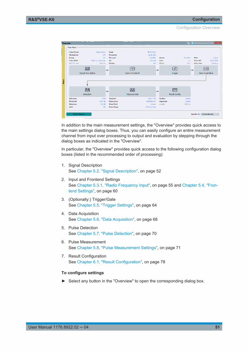
51User Manual 1176.8922.02 ─ 04
In addition to the main measurement settings, the "Overview" provides quick access tothe main settings dialog boxes. Thus, you can easily configure an entire measurementchannel from input over processing to output and evaluation by stepping through thedialog boxes as indicated in the "Overview".
In particular, the "Overview" provides quick access to the following configuration dialogboxes (listed in the recommended order of processing):
1. Signal DescriptionSee Chapter 5.2, "Signal Description", on page 52
2. Input and Frontend SettingsSee Chapter 5.3.1, "Radio Frequency Input", on page 55 and Chapter 5.4, "Fron-tend Settings", on page 60
3. (Optionally:) Trigger/GateSee Chapter 5.5, "Trigger Settings", on page 64
4. Data AcquisitionSee Chapter 5.6, "Data Acquisition", on page 68
5. Pulse DetectionSee Chapter 5.7, "Pulse Detection", on page 70
6. Pulse MeasurementSee Chapter 5.8, "Pulse Measurement Settings", on page 71
7. Result ConfigurationSee Chapter 6.1, "Result Configuration", on page 78
To configure settings
► Select any button in the "Overview" to open the corresponding dialog box.
Configuration Overview

ConfigurationR&S®VSE-K6
52User Manual 1176.8922.02 ─ 04
Select a setting in the channel bar (at the top of the measurement channel tab) tochange a specific setting.
Preset Channel............................................................................................................. 52Specifics for ..................................................................................................................52
Preset ChannelSelect the "Preset Channel" button in the lower left-hand corner of the "Overview" torestore all measurement settings in the current channel to their default values.
Remote command: SYSTem:PRESet:CHANnel[:EXEC] on page 118
Specifics forThe channel may contain several windows for different results. Thus, the settings indi-cated in the "Overview" and configured in the dialog boxes vary depending on theselected window.
Select an active window from the "Specifics for" selection list that is displayed in the"Overview" and in all window-specific configuration dialog boxes.
The "Overview" and dialog boxes are updated to indicate the settings for the selectedwindow.
5.2 Signal Description
Access: "Overview" > "Signal Description"
Or: "Meas Setup" > "Signal Description"
The signal description provides information on the expected input signal, which optimi-zes pulse detection and measurement.
Signal Description

ConfigurationR&S®VSE-K6
53User Manual 1176.8922.02 ─ 04
Pulse Period..................................................................................................................53Pulse Has Droop........................................................................................................... 53Pulse Modulation...........................................................................................................53Timing Auto Mode......................................................................................................... 53Minimum Pulse Width, Maximum Pulse Width..............................................................54Min Pulse Off Time........................................................................................................54Frequency Offset Auto Mode........................................................................................ 54Frequency Offset Value................................................................................................ 54Chirp Rate Auto Mode...................................................................................................54Chirp Rate..................................................................................................................... 54
Pulse PeriodDefines how a pulse is detected.
"High to Low" The pulse period begins with the falling edge of the preceding pulseand ends with the falling edge of the current pulse.
"Low to High" The pulse period begins with the rising edge of the current pulse andend with the rising edge of the succeeding pulse.
Remote command: SENSe:TRACe:MEASurement:DEFine:PULSe:PERiod on page 121
Pulse Has DroopIf enabled, a pulse can be modeled as having amplitude droop, i.e. the pulse top maynot be flat.
Remote command: SENSe:TRACe:MEASurement:DEFine:PULSe:ADRoop on page 120
Pulse ModulationDefines the expected pulse modulation:
"Arbitrary" Modulation not considered (no phase error/frequency error resultsavailable)
"CW" Continuous wave modulation, i.e. only the carrier power is modulated(On/Off)For CW modulation, additional parameters are available to define thefrequency offset.
"Linear FM" Linear frequency modulation (FM) (The frequency changes linearlyover time within each pulse)For linear pulse modulation, additional parameters are available todefine the chirp rate.
Remote command: SENSe:TRACe:MEASurement:DEFine:PULSe:MODulation on page 121
Timing Auto ModeIf enabled, the timing parameters (minimum pulse width, maximum pulse width, mini-mum pulse off time) are determined automatically from the current capture settings.
Remote command: SENSe:TRACe:MEASurement:DEFine:DURation:AUTO on page 119
Signal Description

ConfigurationR&S®VSE-K6
54User Manual 1176.8922.02 ─ 04
Minimum Pulse Width, Maximum Pulse WidthDefines a minimum and maximum pulse width; pulses outside this range are not detec-ted. The available value range is restricted by the sample rate.
Remote command: SENSe:TRACe:MEASurement:DEFine:DURation:MAX on page 119SENSe:TRACe:MEASurement:DEFine:DURation:MIN on page 119
Min Pulse Off TimeThe minimum time the pulse is "off", i.e. the time between successive pulses. Thisvalue is used to determine noise statistics and to reject short drops in amplitude duringpulse "on" time. The available value range is 50ns to 100s, but may be restricted fur-ther by the sample rate.
Remote command: SENSe:TRACe:MEASurement:DEFine:DURation:OFF on page 119
Frequency Offset Auto ModeIf enabled, the frequency offset is estimated automatically for each individual pulse.
Remote command: SENSe:TRACe:MEASurement:DEFine:FREQuency:OFFSet:AUTO on page 120
Frequency Offset ValueDefines a known frequency offset to be corrected in the pulse acquisition data.
Remote command: SENSe:TRACe:MEASurement:DEFine:FREQuency:OFFSet on page 120
Chirp Rate Auto ModeIf enabled, the chirp rate is estimated automatically for each individual pulse.
Remote command: SENSe:TRACe:MEASurement:DEFine:FREQuency:RATE:AUTO on page 120
Chirp RateDefines a known frequency chirp rate (in Hz/μs) to be used to generate an ideal pulsewaveform for computing frequency and phase error parameters. This value is assumedconstant for all measured pulses.
Remote command: SENSe:TRACe:MEASurement:DEFine:FREQuency:RATE on page 120
5.3 Input Source Settings
Access: "Overview" > "Input/Frontend" > "Input Source"
Or: "Input & Output" > "Input Source"
The R&S VSE can control the input sources of the connected instruments.
● Radio Frequency Input............................................................................................55● I/Q File Input............................................................................................................60
Input Source Settings

ConfigurationR&S®VSE-K6
55User Manual 1176.8922.02 ─ 04
5.3.1 Radio Frequency Input
Access: "Overview" > "Input/Frontend" > "Input Source" > "Radio Frequency"
Or: "Input & Output" > "Input Source" > "Radio Frequency"
The default input source for the connected instrument is "Radio Frequency". Depend-ing on the connected instrument, different input parameters are available.
Figure 5-1: RF input source settings for an R&S FSW with B2000 option
Input Type..................................................................................................................... 56Instrument..................................................................................................................... 56Input Coupling .............................................................................................................. 56Direct Path ................................................................................................................... 56High Pass Filter 1 to 3 GHz ..........................................................................................56YIG-Preselector ............................................................................................................57Capture Mode............................................................................................................... 57B2000 State.................................................................................................................. 57RTO Sample Rate.........................................................................................................58RTO Splitter Mode........................................................................................................ 58RTO IP Address............................................................................................................ 58Preselector State...........................................................................................................58
Input Source Settings

ConfigurationR&S®VSE-K6
56User Manual 1176.8922.02 ─ 04
Preselector Mode.......................................................................................................... 5810 dB Minimum Attenuation.......................................................................................... 59Input Selection.............................................................................................................. 59Impedance ................................................................................................................... 59
Input TypeSelects an instrument or a file as the type of input provided to the channel.
Remote command: INSTrument:BLOCk:CHANnel[:SETTings]:SOURce on page 126INPut:SELect on page 125
InstrumentSpecifies a configured instrument to be used for input.
Input CouplingThe RF input of the connected instrument can be coupled by alternating current (AC)or direct current (DC).
AC coupling blocks any DC voltage from the input signal. This is the default setting toprevent damage to the instrument. Very low frequencies in the input signal may be dis-torted.
However, some specifications require DC coupling. In this case, you must protect theinstrument from damaging DC input voltages manually. For details, refer to the datasheet.
Remote command: INPut:COUPling on page 122
Direct PathEnables or disables the use of the direct path for small frequencies.
In spectrum analyzers, passive analog mixers are used for the first conversion of theinput signal. In such mixers, the LO signal is coupled into the IF path due to its limitedisolation. The coupled LO signal becomes visible at the RF frequency 0 Hz. This effectis referred to as LO feedthrough.
To avoid the LO feedthrough the spectrum analyzer provides an alternative signal pathto the A/D converter, referred to as the direct path. By default, the direct path isselected automatically for RF frequencies close to zero. However, this behavior can bedeactivated. If "Direct Path" is set to "Off" , the spectrum analyzer always uses the ana-log mixer path.
"Auto" (Default) The direct path is used automatically for frequencies closeto zero.
"Off" The analog mixer path is always used.
Remote command: INPut:DPATh on page 123
High Pass Filter 1 to 3 GHzActivates an additional internal high-pass filter for RF input signals from 1 GHz to3 GHz. This filter is used to remove the harmonics of the analyzer to measure the har-monics for a DUT, for example.
Input Source Settings

ConfigurationR&S®VSE-K6
57User Manual 1176.8922.02 ─ 04
This function may require an additional hardware option on the connected instrument.
Remote command: INPut:FILTer:HPASs[:STATe] on page 123
YIG-PreselectorActivates or deactivates the YIG-preselector, if available on the connected instrument.
An internal YIG-preselector at the input of the connected instrument ensures thatimage frequencies are rejected. However, this is only possible for a restricted band-width. To use the maximum bandwidth for signal analysis you can deactivate the YIG-preselector at the input of the connected instrument, which can lead to image-fre-quency display.
Remote command: INPut:FILTer:YIG[:STATe] on page 123
Capture ModeDetermines how data from an oscilloscope is input to the R&S VSE software.
This function is only available for a connected R&S RTO with a firmware version3.0.1.1 or higher (for other versions and instruments the input is always I/Q data).
"I/Q" The measured waveform is converted to I/Q data directly on the R&SRTO (requires option R&S RTO-K11), and input to the R&S VSE soft-ware as I/Q data.For data imports with small bandwidths, importing data in this formatis quicker. However, the maximum record length is restricted by theR&S RTO. (Memory options on the R&S RTO are not available forI/Q data.)
"Waveform" The data is input in its original waveform format and converted to I/Qdata in the R&S VSE software. No additional options are required onthe R&S RTO.For data imports with large bandwidths, this format is more conven-ient as it allows for longer record lengths if appropriate memoryoptions are available on the R&S RTO.
"Auto" Uses "I/Q" mode when possible, and "Waveform" only when requiredby the application (e.g. Pulse measurement).
Remote command: INPut:RF:CAPM on page 124
B2000 StateActivates the optional 2 GHz bandwidth extension (R&S FSW-B2000).
Note: The R&S VSE software supports input from a connected R&S FSW with aB2000 option installed. However, the R&S FSW interface to the oscilloscope must beset up and aligned directly on the instrument before the R&S VSE software can startanalyzing the input.The analysis bandwidth is defined in the data acquisition settings of the application asusual. Note that the maximum bandwidth cannot be restricted manually as for otherbandwidth extension options.
Input Source Settings

ConfigurationR&S®VSE-K6
58User Manual 1176.8922.02 ─ 04
Manual operation on the connected oscilloscope, or remote operation other than by theR&S VSE, is not possible while the B2000 option is active.
Remote command: SYSTem:COMMunicate:RDEVice:OSCilloscope[:STATe] on page 126
RTO Sample RateDetermines whether the 10 GHz mode (default) or 20 GHz mode of the connectedoscilloscope is used. The 20 GHZ mode achieves a higher decimation gain, butreduces the record length by half.
Remote command: SYSTem:COMMunicate:RDEVice:OSCilloscope:SRATe on page 127
RTO Splitter ModeActivates the use of the power splitter inserted between the IF 2 GHZ OUT connectorof the R&S FSW and the CH1 and CH3 input connectors of the oscilloscope. Note thatthis mode requires an additional alignment with the power splitter.
For details see the R&S FSW I/Q Analyzer and I/Q Input User Manual.
Remote command: SYSTem:COMMunicate:RDEVice:OSCilloscope:PSMode[:STATe] on page 127
RTO IP AddressWhen using the optional 2 GHz bandwidth extension (R&S FSW-B2000) with an R&SFSW as the connected instrument, the entire measurement, as well as both instru-ments, are controlled by the R&S VSE software. Thus, the instruments must be con-nected via LAN, and the TCPIP address of the oscilloscope must be defined in theR&S VSE software.
For tips on how to determine the computer name or TCPIP address, see the oscillo-scope's user documentation.
Remote command: SYSTem:COMMunicate:RDEVice:OSCilloscope:TCPip on page 126
Preselector StateTurns the preselector on and off.
When you turn on the preselector, you can configure the characteristics of the prese-lector and add the preamplifier into the signal path.
When you turn off the preselector, the signal bypasses the preselector and the pream-plifier, and is fed into the input mixer directly.
Remote command: INPut<n>:PRESelection[:STATe] on page 124
Preselector ModeSelects the preselection filters to be applied to the measurement.
"Auto" Performs a measurement by automatically applying all availablebandpass filters.Available with the optional preamplifier.
Input Source Settings

ConfigurationR&S®VSE-K6
59User Manual 1176.8922.02 ─ 04
"Auto Wide" Performs a measurement by automatically applying the wideband fil-ters consecutively:● Lowpass 40 MHz● Bandpass 30 MHz to 2250 MHz● Bandpass 2 GHz to 8 GHz● Bandpass 8 GHz to 26.5 GHzAvailable with the optional preselector.
"Auto Narrow" Performs a measurement by automatically applying the most suitablenarrowband preselection filters, depending on the bandwidth youhave selected.For measurement frequencies up to 30 MHz, the connected instru-ment uses combinations of lowpass and highpass filters. For higherfrequencies, the connected instrument uses bandpass filters.Available with the optional preselector.
"Manual" Performs a measurement with the filter settings you have definedmanually.
Remote command: INPut<n>:PRESelection:SET on page 124
10 dB Minimum AttenuationTurns the availability of attenuation levels of less than 10 dB on and off.
When you turn on this feature, the attenuation level is always at least 10 dB to protectthe input mixer and avoid accidental setting of 0 dB, especially if you measure DUTswith high RFI voltage.
When you turn it off, you can also select attenuation levels of less than 10 dB.
The setting applies to a manual selection of the attenuation as well as the automaticselection of the attenuation.
Remote command: INPut<n>:ATTenuation:PROTection[:STATe] on page 122
Input SelectionSelects the RF input you would like to use for a measurement.
Note that you cannot use both RF inputs simultaneously.
Remote command: Global: INPut<n>:TYPE on page 125
ImpedanceFor some measurements, the reference impedance for the measured levels of the con-nected instrument can be set to 50 Ω or 75 Ω.
Select 75 Ω if the 50 Ω input impedance is transformed to a higher impedance using a75 Ω adapter of the RAZ type. (That corresponds to 25Ω in series to the input impe-dance of the instrument.) The correction value in this case is 1.76 dB = 10 log (75Ω/50Ω).
Remote command: INPut:IMPedance on page 123
Input Source Settings

ConfigurationR&S®VSE-K6
60User Manual 1176.8922.02 ─ 04
5.3.2 I/Q File Input
Access: "Overview" > "Input/Frontend" > "Input Source" > "IQ File"
Or: "Input & Output" > "Input Source" > "IQ File"
Alternatively to "live" data input from a connected instrument, measurement data to beanalyzed by the R&S VSE software can also be provided "offline" by a stored data file.This allows you to perform a measurement on any instrument, store the results to afile, and analyze the stored data partially or as a whole at any time using the R&S VSEsoftware.
The "Input Source" settings defined in the "Input" dialog box are identical to those con-figured for a specific channel in the "Measurement Group Setup" window.
Input Type..................................................................................................................... 60Input File....................................................................................................................... 60
Input TypeSelects an instrument or a file as the type of input provided to the channel.
Remote command: INSTrument:BLOCk:CHANnel[:SETTings]:SOURce on page 126INPut:SELect on page 125
Input FileSpecifies the I/Q data file to be used for input.
Select "Select File" to open the "Load I/Q File" dialog box.
5.4 Frontend Settings
Access: "Overview" > "Input/Frontend"
Frontend Settings

ConfigurationR&S®VSE-K6
61User Manual 1176.8922.02 ─ 04
The frequency and amplitude settings represent the "frontend" of the measurementsetup.
● Frequency Settings................................................................................................. 61● Amplitude Settings.................................................................................................. 62
5.4.1 Frequency Settings
Access: "Overview" > "Input/Frontend" > "Frequency"
Or: "Input & Output" > "Frequency"
Center Frequency ........................................................................................................ 61Center Frequency Stepsize ..........................................................................................61Frequency Offset ..........................................................................................................62
Center FrequencyDefines the center frequency of the signal in Hertz.
0 Hz ≤ fcenter ≤ fmax
fmax and spanmin depend on the instrument and are specified in the data sheet.
Note: For file input, you can shift the center frequency of the current measurementcompared to the stored measurement data. The maximum shift depends on the chan-nel's current analysis bandwidth.
2maxchannelfile
fileABWABW
CFCFshift
If the file does not provide the center frequency, it is assumed to be 0 Hz.
Remote command: [SENSe:]FREQuency:CENTer on page 128
Center Frequency StepsizeDefines the step size by which the center frequency is increased or decreased usingthe arrow keys.
When you use the mouse wheel, the center frequency changes in steps of only 1/10 ofthe span.
Frontend Settings

ConfigurationR&S®VSE-K6
62User Manual 1176.8922.02 ─ 04
The step size can be coupled to another value or it can be manually set to a fixedvalue.
"= Center" Sets the step size to the value of the center frequency. The usedvalue is indicated in the "Value" field.
"Manual" Defines a fixed step size for the center frequency. Enter the step sizein the "Value" field.
Remote command: [SENSe:]FREQuency:CENTer:STEP on page 129
Frequency OffsetShifts the displayed frequency range along the x-axis by the defined offset.
This parameter has no effect on the instrument's hardware, or on the captured data oron data processing. It is simply a manipulation of the final results in which absolute fre-quency values are displayed. Thus, the x-axis of a spectrum display is shifted by aconstant offset if it shows absolute frequencies, but not if it shows frequencies relativeto the signal's center frequency.
A frequency offset can be used to correct the display of a signal that is slightly distortedby the measurement setup, for example.
The allowed values range from -100 GHz to 100 GHz. The default setting is 0 Hz.
Remote command: [SENSe:]FREQuency:OFFSet on page 130
5.4.2 Amplitude Settings
Access: "Overview" > "Input/Frontend" > "Amplitude"
Or: "Input & Output" > "Amplitude"
Amplitude settings affect the y-axis values.
Reference Level ........................................................................................................... 63└ Shifting the Display ( Offset ).......................................................................... 63
Frontend Settings

ConfigurationR&S®VSE-K6
63User Manual 1176.8922.02 ─ 04
RF Attenuation.............................................................................................................. 63└ Attenuation Mode / Value ...............................................................................63
Using Electronic Attenuation ........................................................................................ 64Input Settings................................................................................................................ 64
└ Preamplifier ....................................................................................................64
Reference LevelDefines the expected maximum reference level. Signal levels above this value may notbe measured correctly. This is indicated by an "IF Overload" status display.
The reference level can also be used to scale power diagrams; the reference level isthen used as the maximum on the y-axis.
Since the hardware of the connected instrument is adapted according to this value, it isrecommended that you set the reference level close above the expected maximum sig-nal level. Thus you ensure an optimum measurement (no compression, good signal-to-noise ratio).
Remote command: DISPlay[:WINDow<n>]:TRACe<t>:Y[:SCALe]:RLEVel on page 130
Shifting the Display ( Offset ) ← Reference LevelDefines an arithmetic level offset. This offset is added to the measured level. In someresult displays, the scaling of the y-axis is changed accordingly.
Define an offset if the signal is attenuated or amplified before it is fed into the R&S VSEso the application shows correct power results. All displayed power level results areshifted by this value.
The setting range is ±200 dB in 0.01 dB steps.
Note, however, that the internal reference level (used to adjust the hardware settings tothe expected signal) ignores any "Reference Level Offset" . Thus, it is important tokeep in mind the actual power level the R&S VSE must handle. Do not rely on the dis-played reference level (internal reference level = displayed reference level - offset).
Remote command: DISPlay[:WINDow<n>]:TRACe<t>:Y[:SCALe]:RLEVel:OFFSet on page 131
RF AttenuationDefines the mechanical attenuation for RF input.
Attenuation Mode / Value ← RF AttenuationThe RF attenuation can be set automatically as a function of the selected referencelevel (Auto mode). This ensures that no overload occurs at the RF INPUT connectorfor the current reference level. It is the default setting.
In "Manual" mode, you can set the RF attenuation in 1 dB steps (down to 0 dB). Otherentries are rounded to the next integer value. The range is specified in the data sheet.If the defined reference level cannot be set for the defined RF attenuation, the refer-ence level is adjusted accordingly and the warning "limit reached" is displayed.
NOTICE! Risk of hardware damage due to high power levels. When decreasing theattenuation manually, ensure that the power level does not exceed the maximum levelallowed at the RF input, as an overload may lead to hardware damage.
Frontend Settings

ConfigurationR&S®VSE-K6
64User Manual 1176.8922.02 ─ 04
Remote command: INPut:ATTenuation on page 132INPut:ATTenuation:AUTO on page 132
Using Electronic AttenuationIf the (optional) Electronic Attenuation hardware is installed on the connected instru-ment, you can also activate an electronic attenuator.
In "Auto" mode, the settings are defined automatically; in "Manual" mode, you candefine the mechanical and electronic attenuation separately.
Note: Note that restrictions may apply concerning which frequencies electronic attenu-ation is available for, depending on which instrument is connected to the R&S VSEsoftware. Check your instrument documentation for details.In "Auto" mode, RF attenuation is provided by the electronic attenuator as much aspossible to reduce the amount of mechanical switching required. Mechanical attenua-tion may provide a better signal-to-noise ratio, however.When you switch off electronic attenuation, the RF attenuation is automatically set tothe same mode (auto/manual) as the electronic attenuation was set to. Thus, the RFattenuation can be set to automatic mode, and the full attenuation is provided by themechanical attenuator, if possible.If the defined reference level cannot be set for the given attenuation, the referencelevel is adjusted accordingly and the warning "limit reached" is displayed in the statusbar.
Remote command: INPut:EATT:STATe on page 133INPut:EATT:AUTO on page 133INPut:EATT on page 132
Input SettingsSome input settings affect the measured amplitude of the signal, as well.
For details see Chapter 5.3.1, "Radio Frequency Input", on page 55.
Preamplifier ← Input SettingsIf the (optional) preamplifier hardware is installed on the connected instrument, a pre-amplifier can be activated for the RF input signal.
You can use a preamplifier to analyze signals from DUTs with low output power.
Depending on the connected instrument, different settings are available. See theinstrument's documentation for details.
Remote command: INPut:GAIN:STATe on page 131INPut:GAIN[:VALue] on page 131
5.5 Trigger Settings
Access: "Overview" > "Trigger" > "Trigger Source"
Trigger Settings

ConfigurationR&S®VSE-K6
65User Manual 1176.8922.02 ─ 04
Or: "Input & Output" > "Trigger"
Trigger settings determine when the input signal is measured.
External triggers from one of the TRIGGER INPUT/OUTPUT connectors on the con-nected instrument are also available.
See the R&S VSE Base Software User Manual.
Trigger Settings.............................................................................................................65└ Trigger Source................................................................................................ 65
└ Free Run ..............................................................................................65└ External Trigger<X> .............................................................................66└ I/Q Power .............................................................................................66└ IF Power .............................................................................................. 66└ RF Power .............................................................................................66
└ Trigger Level ..................................................................................................67└ Drop-Out Time ............................................................................................... 67└ Trigger Offset .................................................................................................67└ Slope ..............................................................................................................67└ Hysteresis ...................................................................................................... 68└ Trigger Holdoff ............................................................................................... 68
Trigger SettingsThe trigger settings define the beginning of a measurement.
Trigger Source ← Trigger SettingsDefines the trigger source. If a trigger source other than "Free Run" is set, "TRG" isdisplayed in the channel bar and the trigger source is indicated.
Note: When triggering is activated, the squelch function is automatically disabled.
Remote command: TRIGger[:SEQuence]:SOURce on page 138
Free Run ← Trigger Source ← Trigger SettingsNo trigger source is considered. Data acquisition is started manually or automaticallyand continues until stopped explicitly.
Remote command: TRIG:SOUR IMM, see TRIGger[:SEQuence]:SOURce on page 138
Trigger Settings

ConfigurationR&S®VSE-K6
66User Manual 1176.8922.02 ─ 04
External Trigger<X> ← Trigger Source ← Trigger SettingsData acquisition starts when the signal fed into the specified input connector or inputchannel of the connected instrument meets or exceeds the specified trigger level.
(See " Trigger Level " on page 67).
Note: Which input and output connectors are available depends on the connectedinstrument. For details, see the instrument's documentation.For a connected R&S RTO, the following signals are used as trigger input:● "External Trigger 1" : EXT TRIGGER INPUT connector on rear panel of instrument● "External Trigger 1" / "External Trigger 2" / "External Trigger 3" : Input at channel
connectors CH 2/3/4 on front panel of instrument
Remote command: TRIG:SOUR EXT, TRIG:SOUR EXT2, TRIG:SOUR EXT3, TRIG:SOUR EXT4See TRIGger[:SEQuence]:SOURce on page 138
I/Q Power ← Trigger Source ← Trigger SettingsTriggers the measurement when the magnitude of the sampled I/Q data exceeds thetrigger threshold.
Remote command: TRIG:SOUR IQP, see TRIGger[:SEQuence]:SOURce on page 138
IF Power ← Trigger Source ← Trigger SettingsThe R&S VSE starts capturing data as soon as the trigger level is exceeded aroundthe third intermediate frequency.
(The third IF represents the center frequency.)
This trigger source is only available for RF input.
The available trigger levels depend on the RF attenuation and preamplification. A refer-ence level offset, if defined, is also considered.
When using the optional 2 GHz bandwidth extension (R&S FSW-B2000) with an IFpower trigger, the IF power trigger corresponds to a "width" trigger on the oscilloscope,with a negative polarity and the range "longer". Thus, data acquisition starts when bothof the following conditions apply to the signal fed into the CH1 input connector on theoscilloscope:● The power level has remained below the specified trigger level for a duration lon-
ger than the drop-out time.● The power level then rises above the specified trigger level.For details on available trigger levels and trigger bandwidths, see the data sheet.
Remote command: TRIG:SOUR IFP, see TRIGger[:SEQuence]:SOURce on page 138
RF Power ← Trigger Source ← Trigger SettingsDefines triggering of the measurement via signals which are outside the displayedmeasurement range.
For this purpose, the software uses a level detector at the first intermediate frequency.
The resulting trigger level at the RF input depends on the RF attenuation and preampli-fication. For details on available trigger levels, see the instrument's data sheet.
Trigger Settings

ConfigurationR&S®VSE-K6
67User Manual 1176.8922.02 ─ 04
Note: If the input signal contains frequencies outside of this range (e.g. for fullspanmeasurements), the measurement may be aborted. A message indicating the allowedinput frequencies is displayed in the status bar.A "Trigger Offset" , "Trigger Polarity" and "Trigger Holdoff" (to improve the trigger sta-bility) can be defined for the RF trigger, but no "Hysteresis" .
Remote command: TRIG:SOUR RFP, see TRIGger[:SEQuence]:SOURce on page 138
Trigger Level ← Trigger SettingsDefines the trigger level for the specified trigger source.
For details on supported trigger levels, see the data sheet.
Remote command: TRIGger[:SEQuence]:LEVel:IFPower on page 136TRIGger[:SEQuence]:LEVel:IQPower on page 136TRIGger[:SEQuence]:LEVel[:EXTernal<port>] on page 135TRIGger[:SEQuence]:LEVel:RFPower on page 137
Drop-Out Time ← Trigger SettingsDefines the time the input signal must stay below the trigger level before triggeringagain.
When using the optional 2 GHz bandwidth extension (R&S FSW-B2000) with an IFpower trigger, the drop-out time defines the width of the robust width trigger. By defaultit is set to 1 μs. For external triggers, no drop-out time is available when using theB2000 option.
Remote command: TRIGger[:SEQuence]:DTIMe on page 134
Trigger Offset ← Trigger SettingsDefines the time offset between the trigger event and the start of the measurement.
Offset > 0: Start of the measurement is delayed
Offset < 0: Measurement starts earlier (pretrigger)
Only possible for zero span (e.g. I/Q Analyzer application) and gated trigger switched off
Maximum allowed range limited by the measurement time:
Pretriggermax = measurement timemax
(If supported by the connected instrument.)
Remote command: TRIGger[:SEQuence]:HOLDoff[:TIME] on page 134
Slope ← Trigger SettingsFor all trigger sources except time, you can define whether triggering occurs when thesignal rises to the trigger level or falls down to it.
When using the optional 2 GHz bandwidth extension (R&S FSW-B2000) with an IFpower trigger, only rising slopes can be detected.
Trigger Settings

ConfigurationR&S®VSE-K6
68User Manual 1176.8922.02 ─ 04
Remote command: TRIGger[:SEQuence]:SLOPe on page 138
Hysteresis ← Trigger SettingsDefines the distance in dB to the trigger level that the trigger source must exceedbefore a trigger event occurs. Setting a hysteresis avoids unwanted trigger eventscaused by noise oscillation around the trigger level.
When using the optional 2 GHz bandwidth extension (R&S FSW-B2000) with an IFpower trigger, the hysteresis refers to the robust width trigger.
This setting is only available for "IF Power" or "Magnitude (Offline)" trigger sources.The range of the value depends on the connected instrument.
Remote command: TRIGger[:SEQuence]:IFPower:HYSTeresis on page 135TRIGger[:SEQuence]:MAPower:HYSTeresis on page 137
Trigger Holdoff ← Trigger SettingsDefines the minimum time (in seconds) that must pass between two trigger events.Trigger events that occur during the holdoff time are ignored.
Remote command: TRIGger[:SEQuence]:IFPower:HOLDoff on page 135TRIGger[:SEQuence]:MAPower:HOLDoff on page 136
5.6 Data Acquisition
Access: "Overview" > "Data Acquisition" > "Acquisition"
Or: "Meas Setup" > "Data Acquisition" > "Acquisition" tab
You must define how much and how data is captured from the input signal.
Data Acquisition

ConfigurationR&S®VSE-K6
69User Manual 1176.8922.02 ─ 04
Filter type...................................................................................................................... 69Measurement Bandwidth.............................................................................................. 69Sample rate...................................................................................................................69Measurement Time....................................................................................................... 69Record length................................................................................................................70
Filter typeDefines the filter to be used for demodulation.
"Flat" Standard flat demodulation filter
"Gauss" Filter with optimized settling behavior (default)
Note: For Gaussian filters whose -3dB bandwidth is large comparedto the maximum I/Q bandwidth, the ideal Gaussian filter shape wouldexceed the maximum I/Q bandwidth at its outer edges. Thus, theactual filter only follows the ideal Gaussian filter shape in the innerrange of the set I/Q bandwidth. At a certain frequency offset it mustdeviate from the ideal Gauss filter and drop off faster.For details see Chapter D, "Effects of Large Gauss Filters",on page 336.
Remote command: [SENSe:]BWIDth:DEMod:TYPE on page 142
Measurement BandwidthThe measurement bandwidth is defined by the used filter and the sample rate. Either aflat or a Gauss filter are available. For information on supported sample rates and filterbandwidths see the data sheet.
Remote command: [SENSe:]BANDwidth:DEMod on page 142
Sample rateThe sample rate for I/Q data acquisition is indicated for reference only. It is calculatedfrom the defined measurement bandwidth and measurement time, or taken from theI/Q data input file.
Measurement TimeDefines how long data is captured for analysis ("Meas Time"), or how many samplesare captured in each record ("Record Length").
The maximum measurement time in the R&S VSE Pulse application is limited only bythe available memory ("memory limit reached" message is shown in status bar). Note,however, that increasing the measurement time (and thus reducing the available mem-ory space) may restrict the number of measurement channels that can be activatedsimultaneously on the R&S VSE.
Remote command: [SENSe:]SWEep:TIME on page 143
Data Acquisition

ConfigurationR&S®VSE-K6
70User Manual 1176.8922.02 ─ 04
Record lengthThe record length for I/Q data acquisition is indicated for reference only. It is calculatedfrom the defined measurement bandwidth and measurement time, or taken from theI/Q data input file.
5.7 Pulse Detection
Access: "Overview" > "Detection"
Or: "Meas Setup" > "Detection"
The pulse detection settings define the conditions under which a pulse is detectedwithin the input signal.
Reference Source......................................................................................................... 70Threshold...................................................................................................................... 71Hysteresis..................................................................................................................... 71Detection Limit.............................................................................................................. 71Maximum Pulse Count.................................................................................................. 71
Reference SourceDefines the level to be used as a reference for the pulse detection threshold.
"Reference" Current reference level
"Peak" Peak level as measured over the entire capture data interval
"Noise" Noise level determined from the current capture data according to theMin Pulse Off Time parameter set in Signal Description.
Pulse Detection

ConfigurationR&S®VSE-K6
71User Manual 1176.8922.02 ─ 04
"Absolute" Absolute level defined by the Threshold
Remote command: [SENSe:]DETect:REFerence on page 145
ThresholdThe threshold determines whether a pulse is detected or not. The top of a pulse mustexceed the threshold in order to be detected. The threshold is defined in dB in relationto the defined reference, or as an absolute threshold in dBm.
Remote command: [SENSe:]DETect:THReshold on page 145
HysteresisDefines a hysteresis for pulse detection in dB in relation to the defined threshold. Aslong as the signal does not exceed the hysteresis, the next threshold crossing isignored.
Remote command: [SENSe:]DETect:HYSTeresis on page 144
Detection LimitRestricts the number of pulses to be detected. When the maximum number is excee-ded, measurement is stopped for the current capture buffer. This limitation can be usedto speed up the measurement if only a small number of pulses is of interest.
Remote command: [SENSe:]DETect:LIMit on page 144
Maximum Pulse CountDefines the maximum number of pulses to be detected.
This limit is ignored if Detection Limit is disabled.
Remote command: [SENSe:]DETect:LIMit:COUNt on page 144
5.8 Pulse Measurement Settings
Access: "Overview" > "Measurement"
The pulse measurement settings determine how much data is measured for eachpulse, in relation to defined levels, points, or ranges. Which definition is actually usedduring measurement depends on the selected evaluation method.
● Measurement Levels...............................................................................................71● Measurement Point.................................................................................................74● Measurement Range...............................................................................................76
5.8.1 Measurement Levels
Access: "Overview" > "Measurement" > "Meas Levels" tab
Pulse Measurement Settings

ConfigurationR&S®VSE-K6
72User Manual 1176.8922.02 ─ 04
Or: "Meas Setup" > "Pulse Meas" > "Meas Levels"tab
Some measurements are performed depending on defined levels.
Position......................................................................................................................... 72Measurement Algorithm................................................................................................ 73Ripple Portion................................................................................................................73Reference Level Unit.....................................................................................................73High (Distal) Threshold................................................................................................. 73Mid (Mesial) Threshold..................................................................................................73Low (Proximal) Threshold............................................................................................. 73Boundary.......................................................................................................................74
PositionDetermines where the 100% value (from base to top) for the rise and fall time mea-surements is calculated.
This allows you to consider a "droop" in the pulse top during the pulse measurements.If a droop is to be considered, the 100% value must be calculated separately for therising and falling edges.
"Edge" The 100% value is measured separately for the rising and fallingedges.
Pulse Measurement Settings

ConfigurationR&S®VSE-K6
73User Manual 1176.8922.02 ─ 04
"Center" The 100% value is measured at the pulse center and used for allmeasurements.
Remote command: SENSe:TRACe:MEASurement:DEFine:COMPensate:ADRoop on page 147
Measurement AlgorithmDefines the algorithm used to detect the pulse top level.
"Mean" The arithmetic average of the measured values
"Median" The level for which half the values lie above, the other half below inthe histogram
"Peak Power" The peak power is used to detect the pulse top level.
Remote command: SENSe:TRACe:MEASurement:ALGorithm on page 146
Ripple PortionDefines the portion of the pulse top which is used to measure the ripple.
Remote command: SENSe:TRACe:MEASurement:DEFine:RIPPle on page 147
Reference Level UnitDefines the unit of the pulse amplitude values, i.e. whether magnitude (V) or power (W,dBm) values are used to determine the threshold levels for fall and rise times.
Remote command: SENSe:TRACe:MEASurement:DEFine:AMPLitude:UNIT on page 146
High (Distal) ThresholdThe upper threshold in percent of the pulse amplitude used to signify the end of a ris-ing or beginning of a falling signal level.
Remote command: SENSe:TRACe:MEASurement:DEFine:TRANsition:HREFerence on page 147
Mid (Mesial) ThresholdThe middle threshold in percent of the pulse amplitude used to signify the mid-transi-tion level between pulse states.
Remote command: SENSe:TRACe:MEASurement:DEFine:TRANsition:REFerence on page 148
Low (Proximal) ThresholdThe lower threshold in percent of the pulse amplitude used to signify the end of a fall-ing or beginning of a rising signal level.
Remote command: SENSe:TRACe:MEASurement:DEFine:TRANsition:LREFerence on page 147
Pulse Measurement Settings

ConfigurationR&S®VSE-K6
74User Manual 1176.8922.02 ─ 04
BoundaryThe boundary in percent of the pulse amplitude to either side of the pulse top (ONstate). Used to determine the settling time, for example. Once the signal remains withinthe boundary, it is assumed to have settled.
Remote command: SENSe:TRACe:MEASurement:DEFine:BOUNdary:TOP on page 146
5.8.2 Measurement Point
Access: "Overview" > "Measurement" > "Meas Point" tab
Or: "Meas Setup" > "Pulse Meas" > "Meas Point" tab
Some specific pulse parameters, e.g. the phase or the frequency, are determined at aspecific time instant (measurement point) within the pulse. You can configure this pointbased on a reference and offset value.
Measurement Point Reference..................................................................................... 74Offset.............................................................................................................................75Averaging Window........................................................................................................ 75Reference for Pulse-Pulse Measurements................................................................... 75
Measurement Point ReferenceDefines the reference which the Offset refers to.
Pulse Measurement Settings

ConfigurationR&S®VSE-K6
75User Manual 1176.8922.02 ─ 04
"Rise" The measurement point is defined in reference to the rising edge(mid-level crossing).
"Center" The measurement point is defined in reference to the center of thepulse (equal distance from the rising and falling mid-level crossings).
"Fall" The measurement point is defined in reference to the falling edge(mid-level crossing).
Remote command: SENSe:TRACe:MEASurement:DEFine:PULSe:INSTant:REFerence on page 149
OffsetThe time offset of the measurement point in reference to the pulse center or an edge,depending on the Measurement Point Reference setting.
The "Offset" is indicated in the dialog box.
Remote command: SENSe:TRACe:MEASurement:DEFine:PULSe:INSTant on page 148
Averaging WindowMeasurement point results are averaged over a window centered at the measurementpoint. The length of the averaging window in seconds can be defined. A minimumlength of 1 sample is enforced internally.
Remote command: SENSe:TRACe:MEASurement:DEFine:PULSe:INSTant:AWINdow on page 148
Reference for Pulse-Pulse MeasurementsReference pulse on which relative pulse results are based (e.g. for traces normalizedto reference pulse, see Chapter 4.4.2, "Normalizing Traces", on page 45).
"Fixed" A fixed pulse numberRelative results for the specified pulse number itself are not valid andare indicated as "...".
"Selected" The currently selected pulse (see Chapter 6.1.1, "Pulse Selection",on page 78)Relative results for the selected pulse itself are not valid and are indi-cated as "...".If you change the value for the reference pulse here, the Chap-ter 6.1.1, "Pulse Selection", on page 78 value is adapted accord-ingly, and vice versa.
"Before Pulse" The nth pulse before the currently evaluated pulse, where n is thespecified numberNo values are available for the first n pulses, as no valid referencepulse is available. These results are indicated as "...".For example, a value of 2 will use row 1 as the reference row forPulse-Pulse results for pulse number 3. In this case, pulse numbers 1and 2 will not have a valid reference row and the Pulse-Pulse resultswill be invalid for these rows.
Pulse Measurement Settings

ConfigurationR&S®VSE-K6
76User Manual 1176.8922.02 ─ 04
"After Pulse" The nth pulse after the currently evaluated pulse, where n is thespecified numberNo values are available for the last n pulses, as no valid referencepulse is available. These results are indicated as "...".For example, a value of 2 will use row 5 as the reference row forPulse-Pulse results for pulse number 3. In this case, the last twopulse rows will not have a valid reference row and the Pulse-Pulseresults will be invalid for these rows.
Remote command: SENSe:TRACe:MEASurement:DEFine:PULSe:REFerence:POSitionon page 149SENSe:TRACe:MEASurement:DEFine:PULSe:REFerence on page 149
5.8.3 Measurement Range
Access: "Overview" > "Measurement" > "Meas Range" tab
Or: "Meas Setup" > "Pulse Meas" > "Meas Range"tab
Some measurements are performed over a range within the pulse, for example thephase or frequency deviation. The measurement range is specified either by start andend points relative to the rising and falling edges, or as a proportion of the pulse top.
Reference, Length, Offset............................................................................................. 76
Reference, Length, OffsetDefines the reference for the measurement range definition. Depending on theselected reference type, an additional setting is available to define the range.
Pulse Measurement Settings

ConfigurationR&S®VSE-K6
77User Manual 1176.8922.02 ─ 04
"Center" Defines a relative range around the center of the pulse. The range isdefined by its length in percent of the pulse top.
"Edge" Defines the start and stop of the measurement range with respect tothe pulse edges. The range is defined by a time offset from the mid-dle of the rising edge and a time offset from the middle of the fallingedge.
Remote command: SENSe:TRACe:MEASurement:DEFine:PULSe:ESTimation:REFerenceon page 151Relative range (Center):SENSe:TRACe:MEASurement:DEFine:PULSe:ESTimation:LENGth on page 150Absolute range (Edge):SENSe:TRACe:MEASurement:DEFine:PULSe:ESTimation:OFFSet:LEFTon page 151SENSe:TRACe:MEASurement:DEFine:PULSe:ESTimation:OFFSet:RIGHton page 151
5.9 Automatic Settings
Access: "Auto Set" toolbar
Some settings can be adjusted by the R&S VSE automatically according to the currentmeasurement settings.
Auto Scale Continuous (All).......................................................................................... 77Auto Scale Once (All)....................................................................................................77
Auto Scale Continuous (All)Automatically determines the optimal result range and reference level position for eachnew measurement in all displayed diagrams (for graphical or pulse-based result dis-plays only).
Remote command: SENS:TRAC:MEAS:DEF:RRAN:AUTO ON, see SENSe:TRACe:MEASurement:DEFine:RRANge:AUTO on page 163DISP:TRAC:Y:SCAL:AUTO ON, see DISPlay[:WINDow<n>]:TRACe<t>:Y[:SCALe]:AUTO on page 232
Auto Scale Once (All)Automatically determines the optimal result range and reference level position once forthe current measurement settings in all displayed diagrams and pulse-based result dis-plays. All automatic scaling functions are then switched off.
Remote command: SENS:TRAC:MEAS:DEF:RRAN:AUTO ONCE, see SENSe:TRACe:MEASurement:DEFine:RRANge:AUTO on page 163DISP:TRAC:Y:SCAL:AUTO ONCE, see DISPlay[:WINDow<n>]:TRACe<t>:Y[:SCALe]:AUTO on page 232
Automatic Settings

AnalysisR&S®VSE-K6
78User Manual 1176.8922.02 ─ 04
6 AnalysisAfter a Pulse measurement has been performed, you can analyze the results in vari-ous ways.
● Result Configuration................................................................................................78● Markers................................................................................................................... 95● Trace Configuration...............................................................................................103
6.1 Result Configuration
Access: "Overview" > "Result Configuration"
Or: "Meas Setup" > "Result"
Some evaluation methods require or allow for additional settings to configure the resultdisplay. Note that the available settings depend on the selected window (see " Specif-ics for " on page 52).
● Pulse Selection....................................................................................................... 78● Result Range.......................................................................................................... 79● Result Range Spectrum Configuration....................................................................80● Result Range Frequency Configuration..................................................................82● Parameter Configuration for Result Displays..........................................................82● Table Configuration.................................................................................................88● Y-Scaling.................................................................................................................92● Units........................................................................................................................94
6.1.1 Pulse Selection
Access: "Meas Setup" > "Selected Pulse"
The pulse traces (frequency, magnitude and pulse vs. time) always display the tracefor one specific pulse, namely the currently selected pulse. The currently selectedpulse is highlighted blue in the "Pulse Results" and "Pulse Statistics" displays.
As soon as a new pulse is selected, all pulse-specific displays are automatically upda-ted.
You can also select a pulse simply by clicking on it in the Pulse Results display.
Remote command:
SENSe:TRACe:MEASurement:DEFine:PULSe:SELected on page 162
Result Configuration

AnalysisR&S®VSE-K6
79User Manual 1176.8922.02 ─ 04
6.1.2 Result Range
Access: "Overview" > "Result Configuration" > "Result Range" tab
Or: "Meas Setup" > "Result" > "Result Range" tab
The result range determines which data is displayed on the screen (see also "Mea-surement range vs result range" on page 11). This range applies to the pulse magni-tude, frequency and phase vs time displays.
The range is defined by a reference point, alignment and the range length.
Automatic Range Scaling..............................................................................................79Result Range Reference Point......................................................................................80Offset.............................................................................................................................80Alignment...................................................................................................................... 80Length........................................................................................................................... 80
Automatic Range ScalingDefines whether the result range length is determined automatically according to thewidth of the selected pulse (see Chapter 6.1.1, "Pulse Selection", on page 78).
Note: The result range is applied to all pulse-based result displays.
"OFF" Switches automatic range scaling off
"ON" Switches automatic range scaling on
Result Configuration

AnalysisR&S®VSE-K6
80User Manual 1176.8922.02 ─ 04
"ONCE" Executes automatic range scaling once and then switches it off
Remote command: SENSe:TRACe:MEASurement:DEFine:RRANge:AUTO on page 163
Result Range Reference PointDefines the reference point for positioning the result range. The Offset is given withrespect to this value.
"Rise" The result range is defined in reference to the rising edge.
"Center" The result range is defined in reference to the center of the pulse top.
"Fall" The result range is defined in reference to the falling edge.
Remote command: SENSe:TRACe:MEASurement:DEFine:RRANge:REFerence on page 164
OffsetThe offset in seconds from the pulse edge or center at which the result range referencepoint occurs.
Remote command: SENSe:TRACe:MEASurement:DEFine:RRANge:OFFSet on page 164
AlignmentDefines the alignment of the result range in relation to the selected Result Range Ref-erence Point.
"Left" The result range starts at the pulse center or selected edge.
"Center" The result range is centered around the pulse center or selectededge.
"Right" The result range ends at the pulse center or selected edge.
Remote command: SENSe:TRACe:MEASurement:DEFine:RRANge:ALIGnment on page 163
LengthDefines the length or duration of the result range.
Remote command: SENSe:TRACe:MEASurement:DEFine:RRANge:LENGth on page 163
6.1.3 Result Range Spectrum Configuration
Access: "Overview" > "Result Configuration" > "Result Range" tab > "Result RangeSpectrum" tab
For the Result Range Spectrum display additional settings are available for the FFT.
Result Configuration

AnalysisR&S®VSE-K6
81User Manual 1176.8922.02 ─ 04
Window Type................................................................................................................ 81ResBW Manual............................................................................................................. 81RBW Auto..................................................................................................................... 81
Window TypeUsed FFT window type for Result Range Spectrum. The same window types are avail-able as for Parameter Spectrum displays (see "Window functions" on page 42).
Remote command: CALCulate<n>:RRSPectrum:WINDow on page 207
ResBW ManualDefines the resolution bandwidth for the Result Range Spectrum.
The resolution bandwidth defines the minimum frequency separation at which the indi-vidual components of a spectrum can be distinguished. Small values lead to high preci-sion results, as the distance between two distinguishable frequencies is small, butrequire a larger measurement interval (that is: longer Result Range length) for the cal-culation. Higher values decrease the precision, but can increase measurement speed.
Remote command: CALCulate<n>:RRSPectrum:RBW on page 208
RBW AutoIf activated, a resolution bandwidth is selected automatically which provides a goodbalance between fast measurement speed and high spectral resolution.
Remote command: CALCulate<n>:RRSPectrum:AUTO on page 208
Result Configuration

AnalysisR&S®VSE-K6
82User Manual 1176.8922.02 ─ 04
6.1.4 Result Range Frequency Configuration
FM Video BandwidthAdditional filters applied after demodulation help filter out unwanted signals, or correctpre-emphasized input signals.● Relative low pass filters:
Relative filters (3 dB) can be selected in % of the analysis (demodulation) band-width. The filters are designed as 5th-order Butterworth filters (30 dB/octave) andactive for all demodulation bandwidths.
● "None" deactivates the FM video bandwidth (default).
Remote command: [SENSe:]DEMod:FMVF:TYPE on page 143
6.1.5 Parameter Configuration for Result Displays
Access: "Overview" > "Result Configuration" > "Parameter" tab
Or: "Meas Setup" > "Result" > "Parameter" tab
For parameter trend or distribution displays you can define which parameters are to beevaluated in each window.
● Parameter Distribution Configuration......................................................................82● Parameter Spectrum Configuration.........................................................................84● Parameter Trend Configuration...............................................................................87
6.1.5.1 Parameter Distribution Configuration
Access: "Overview" > "Result Configuration" > "Parameter" > "Distribution"
Or: "Meas Setup" > "Result" > "Parameter" tab > "Distribution" tab
The parameter distribution evaluations allow you to visualize the number of occurren-ces for a specific parameter value within the current capture buffer. For each parame-ter distribution window you can configure which measured parameter is to be dis-played.
Result Configuration

AnalysisR&S®VSE-K6
83User Manual 1176.8922.02 ─ 04
This tab is only available for windows with a Parameter Distribution evaluation.
Parameter Group.......................................................................................................... 83X-Axis............................................................................................................................83Y-Axis............................................................................................................................84Histogram Bins..............................................................................................................84Display Limit Lines........................................................................................................ 84
Parameter GroupDefines the group of parameters from which one can be selected to display the distri-bution of the measured values on the y-axis. For a description of the parameters seeChapter 3.1, "Pulse Parameters", on page 11.
X-AxisDefines the parameter for which the values are displayed on the x-axis. The availableparameters depend on the selected Parameter Group.
Remote command: CALCulate<n>:DISTribution:<GroupName> <X-Axis>,<Y-Axis>, see e.g.CALCulate<n>:DISTribution:FREQuency on page 166
Result Configuration

AnalysisR&S®VSE-K6
84User Manual 1176.8922.02 ─ 04
Y-AxisDefines the scaling of the y-axis.
"Pulse count" Number of pulses in which the value occurred.
"Occurrence" Number of occurrences in percent of all measured values.
Histogram BinsNumber of columns on the x-axis, i.e. the number of measurement value ranges forwhich the occurrences are determined.
Remote command: CALCulate<n>:DISTribution:NBINs on page 167
Display Limit LinesHides or shows the limit lines in the selected Parameter Trend or Parameter Distribu-tion result display. You can drag these lines to a new position in the window. The newposition is maintained, the limit check is repeated, and the results of the limit check inany active table displays are adapted.
Note that this function only has an effect on the visibility of the lines in the graphicaldisplays, it does not affect the limit check in general or the display of the limit checkresults in the table displays.
Remote command: CALCulate<n>:DISTribution:LLINes[:STATe] on page 167CALCulate<n>:TRENd:LLINes[:STATe] on page 188
6.1.5.2 Parameter Spectrum Configuration
Access: "Overview" > "Result Configuration" > "Parameter" > "Spectrum"
Calculates an FFT for a selected column of the Pulse Results table. This "spectrum"allows you to easily determine the frequency of periodicities in the pulse parameters.
For each Parameter Spectrum window you can configure which measured parameteris to be displayed and how the spectrum is determined.
Result Configuration

AnalysisR&S®VSE-K6
85User Manual 1176.8922.02 ─ 04
This tab is only available for windows with a Parameter Spectrum evaluation.
For more information on how the parameter spectrum is calculated see Chapter 4.3,"Parameter Spectrum Calculation", on page 41.
Parameter Group.......................................................................................................... 85Parameter..................................................................................................................... 86Full Auto........................................................................................................................ 86Maximum Frequency.....................................................................................................86Window Type................................................................................................................ 86Block Size..................................................................................................................... 86Gap Threshold.............................................................................................................. 86Section Threshold......................................................................................................... 86
Parameter GroupDefines the group of parameters from which one can be selected to display the FFT ofthe measured values. For a description of the parameters see Chapter 3.1, "PulseParameters", on page 11.
Result Configuration

AnalysisR&S®VSE-K6
86User Manual 1176.8922.02 ─ 04
ParameterDefines the parameter for which the FFT is calculated and displayed. The availableparameters depend on the selected Parameter Group.
Remote command: CALCulate<n>:PSPectrum:<GroupName> <X-Axis>, see e.g. CALCulate<n>:PSPectrum:FREQuency on page 173
Full AutoDetermines the Parameter Spectrum settings automatically. For most measurementcases, automatic configuration should be suitable.
If enabled, the individual settings are not available.
Remote command: CALCulate<n>:PSPectrum:AUTO on page 171
Maximum FrequencyDefines the maximum frequency span for which the Spectrum is calculated. Internally,the span is limited by the number of possible interpolation samples (100 000). Limitingthe span to the actually required frequencies decreases the calculation time and canimprove the obtained RBW.
Remote command: CALCulate<n>:PSPectrum:MAXFrequency on page 174
Window TypeUsed FFT window type
Remote command: CALCulate<n>:PSPectrum:WINDow on page 178
Block SizeSize of block used in spectrum calculation. Windowing and averaging are used to com-bine blocks. The block size also determines the resulting RBW of the spectrum.
Remote command: CALCulate<n>:PSPectrum:BLOCksize on page 172
Gap ThresholdMinimum time that must pass before a gap is detected as such.
Remote command: CALCulate<n>:PSPectrum:GTHReshold on page 174
Section ThresholdMinimum section size as a percentage of the block size. Sections that are smaller thanthe threshold are ignored and considered to be in the detected gap.
Remote command: CALCulate<n>:PSPectrum:STHReshold on page 177
Result Configuration

AnalysisR&S®VSE-K6
87User Manual 1176.8922.02 ─ 04
6.1.5.3 Parameter Trend Configuration
Access: "Overview" > "Result Configuration" > "Parameter" tab > "Trend" tab
Or: "Meas Setup" > "Result" > "Parameter" tab > "Trend" tab
The parameter trend result displays allow you to visualize changes in a specific param-eter for all measured pulses within the current capture buffer. For each parametertrend window you can configure which measured parameter is to be displayed on thex-axis and which on the y-axis.
This tab is only available for windows with a Parameter Trend result display.
Parameter Group Y....................................................................................................... 88Y-Axis............................................................................................................................88Parameter Group X....................................................................................................... 88X-Axis............................................................................................................................88Display Limit Lines........................................................................................................ 88
Result Configuration

AnalysisR&S®VSE-K6
88User Manual 1176.8922.02 ─ 04
Parameter Group YDefines the group of parameters from which one can be selected to display the trendon the y-axis. For a description of the parameters see Chapter 3.1, "Pulse Parame-ters", on page 11.
Y-AxisDefines the parameter for which the trend is displayed on the y-axis. The availableparameters depend on the selected "Parameter Group Y" on page 88.
Remote command: CALCulate<n>:TRENd:<GroupName>:Y, see e.g. CALCulate<n>:TRENd:FREQuency:Y on page 187CALCulate<n>:TRENd:<GroupName> Y,X, see e.g. CALCulate<n>:TRENd:FREQuency on page 185
Parameter Group XDefines the group of parameters from which one can be selected to display the trendon the x-axis. For a description of the parameters see Chapter 3.1, "Pulse Parame-ters", on page 11.
X-AxisDefines the parameter for which the trend is displayed on the y-axis. The availableparameters depend on the selected Parameter Group X.
Remote command: CALCulate<n>:TRENd:<GroupName>:X, see e.g. CALCulate<n>:TRENd:FREQuency:X on page 186CALCulate<n>:TRENd:<GroupName> Y,X, see e.g. CALCulate<n>:TRENd:FREQuency on page 185
Display Limit LinesHides or shows the limit lines in the selected Parameter Trend or Parameter Distribu-tion result display. You can drag these lines to a new position in the window. The newposition is maintained, the limit check is repeated, and the results of the limit check inany active table displays are adapted.
Note that this function only has an effect on the visibility of the lines in the graphicaldisplays, it does not affect the limit check in general or the display of the limit checkresults in the table displays.
Remote command: CALCulate<n>:DISTribution:LLINes[:STATe] on page 167CALCulate<n>:TRENd:LLINes[:STATe] on page 188
6.1.6 Table Configuration
Access: "Overview" > "Result Configuration" > "Table Config"
Or: "Meas Setup" > "Result" > "Table Config" tab
Result Configuration

AnalysisR&S®VSE-K6
89User Manual 1176.8922.02 ─ 04
During each measurement, a large number of statistical and characteristic values aredetermined. The "Pulse Statistics" and "Pulse Results" result displays provide an over-view of the parameters selected here.
Note that the "Result Configuration" dialog box is window-specific; table configurationsettings are only available if a table display is selected. However, the table configura-tion applies to all tables, regardless of which table is selected.
Select the parameters to be included in the tables, and the required unit scaling, ifavailable. For a description of the individual parameters see Chapter 3.1, "PulseParameters", on page 11.
Remote command:
CALCulate<n>:TABLe:<GroupName>:<ParamName>, see Chapter 8.4.10.7, "Con-figuring the Statistics and Parameter Tables", on page 208
6.1.6.1 Table Export Configuration
Access: "Overview" > "Result Configuration" > "Table Config" > "Table Export"
Table results can be exported to an ASCII file for further evaluation in other (external)applications.
The settings are window-specific and only available for result tables.
Result Configuration

AnalysisR&S®VSE-K6
90User Manual 1176.8922.02 ─ 04
The result tables can be exported either directly in the settings dialog box or via the"Export" function in the "Save/Recall" menu (via the toolbar).
Columns to Export.........................................................................................................90Decimal Separator ....................................................................................................... 90Export table to ASCII File .............................................................................................90
Columns to ExportDefines which of the result table columns are to be included in the export file.
"Visible" Only the currently visible columns in the result display are exported.
"All" All columns, including currently hidden ones, for the result display areexported.
Remote command: MMEMory:STORe<n>:TABLe on page 315
Decimal SeparatorDefines the decimal separator for floating-point numerals for the data export/importfiles. Evaluation programs require different separators in different languages.
Remote command: FORMat:DEXPort:DSEParator on page 314
Export table to ASCII FileOpens a file selection dialog box and saves the selected result table in ASCII format(.DAT) to the specified file and directory.
For details on the file format, see Chapter C, "Reference: ASCII File Export Format",on page 334.
Remote command: MMEMory:STORe<n>:TABLe on page 315
Result Configuration

AnalysisR&S®VSE-K6
91User Manual 1176.8922.02 ─ 04
6.1.6.2 Limit Settings for Table Displays
Access: "Overview" > "Result Configuration" > "Table Config" > "Limits"
Measurement results can be checked against defined limits and the results of the limitcheck can then be indicated in the Result Table.
For details on limits see "Pulse Results" on page 32.
The settings are window-specific and only available for result tables.
Optionally, limit lines can be displayed in the Parameter Distribution and ParameterTrend diagrams. You can drag these lines to a new position in the window. The newposition is maintained, the limit check is repeated, and the results of the limit check inany active table displays are adapted.
Parameter Group.......................................................................................................... 92Parameter..................................................................................................................... 92Activating a limit check for a parameter........................................................................ 92Defining lower and upper limits for a parameter........................................................... 92Deactivating a limit check for an entire parameter group..............................................92Deactivating all limit checks for all parameter groups................................................... 92
Result Configuration

AnalysisR&S®VSE-K6
92User Manual 1176.8922.02 ─ 04
Parameter GroupDefines the group of parameters from which one can be selected to define limits. For adescription of the parameters see Chapter 3.1, "Pulse Parameters", on page 11.
ParameterDefines the parameter for which the limits are to be defined. The available parametersdepend on the selected Parameter Group.
Activating a limit check for a parameterTo activate a limit check for the selected parameter, set "Limit On/Off" to "ON".
Remote command: CALCulate<n>:TABLe:<ParameterGroup>:<Parameter>:LIMit:STATeon page 227
Defining lower and upper limits for a parameterThe "Lower Limit" and "Upper Limit" define the valid value range for the limit check forthe selected parameter.
Remote command: CALCulate<n>:TABLe:<ParameterGroup>:<Parameter>:LIMit on page 229
Deactivating a limit check for an entire parameter groupTo deactivate all limits for an entire parameter group at once, select "Turn off all limitsin group". This function is identical to setting "Limit On/Off" to "OFF" for each parame-ter in the group.
Remote command: CALCulate<n>:TABLe:<ParameterGroup>:ALL:LIMit:STATe on page 229
Deactivating all limit checks for all parameter groupsTo deactivate all limits for all parameter groups at once, select "Turn off limits". Thisfunction is identical to setting "Limit On/Off" to "OFF" for each parameter in each group.
Remote command: CALCulate<n>:TABLe:ALL:LIMit:STATe on page 229
6.1.7 Y-Scaling
Access: "Overview" > "Result Configuration" > "Y Scaling"
Or: "Meas Setup" > "Result" > "Y Scaling" tab
The scaling for the vertical axis is highly configurable, using either absolute or relativevalues.
Result Configuration

AnalysisR&S®VSE-K6
93User Manual 1176.8922.02 ─ 04
Automatic Grid Scaling..................................................................................................93Auto Scale Once .......................................................................................................... 94Absolute Scaling (Min/Max Values).............................................................................. 94Relative Scaling (Reference/ per Division)....................................................................94
└ Per Division.....................................................................................................94└ Ref Position.....................................................................................................94└ Ref Value........................................................................................................ 94
Automatic Grid ScalingThe y-axis is scaled automatically according to the current measurement settings andresults (continuously).
Note: If a limit is defined for a parameter that is displayed in a Parameter Trend dia-gram (see "Activating a limit check for a parameter" on page 92), autoscaling is notavailable for the axis this parameter is displayed on.Note: Tip: To update the scaling automatically once when this setting for continuousscaling is off, use the " Auto Scale Once " on page 94 button or the softkey in theAUTO SET menu.
Remote command: DISPlay[:WINDow<n>]:TRACe<t>:Y[:SCALe]:AUTO on page 232
Result Configuration

AnalysisR&S®VSE-K6
94User Manual 1176.8922.02 ─ 04
Auto Scale OnceAutomatically determines the optimal range and reference level position to be dis-played for the current measurement settings.
The display is only set once; it is not adapted further if the measurement settings arechanged again.
Remote command: DISPlay[:WINDow<n>]:TRACe<t>:Y[:SCALe]:AUTO on page 232
Absolute Scaling (Min/Max Values)Define the scaling using absolute minimum and maximum values.
Remote command: DISPlay[:WINDow<n>]:TRACe<t>:Y[:SCALe]:MAXimum on page 233DISPlay[:WINDow<n>]:TRACe<t>:Y[:SCALe]:MINimum on page 233
Relative Scaling (Reference/ per Division)Define the scaling relative to a reference value, with a specified value range per divi-sion.
Per Division ← Relative Scaling (Reference/ per Division)Defines the value range to be displayed per division of the diagram (1/10 of totalrange).
Note: The value defined per division refers to the default display of 10 divisions on they-axis. If fewer divisions are displayed (e.g. because the window is reduced in height),the range per division is increased in order to display the same result range in thesmaller window. In this case, the per division value does not correspond to the actualdisplay.
Remote command: DISPlay[:WINDow<n>]:TRACe<t>:Y[:SCALe]:PDIVision on page 233
Ref Position ← Relative Scaling (Reference/ per Division)Defines the position of the reference value in percent of the total y-axis range.
Remote command: DISPlay[:WINDow<n>]:TRACe<t>:Y[:SCALe]:RPOSition on page 234
Ref Value ← Relative Scaling (Reference/ per Division)Defines the reference value to be displayed at the specified reference position.
Remote command: DISPlay[:WINDow<n>]:TRACe<t>:Y[:SCALe]:RVALue on page 234
6.1.8 Units
Access: "Overview" > "Result Configuration" > "Units"
Or: "Meas Setup" > "Result" > "Units" tab
The unit for phase display is configurable.
Result Configuration

AnalysisR&S®VSE-K6
95User Manual 1176.8922.02 ─ 04
Phase Unit.....................................................................................................................95Phase Normalization..................................................................................................... 95Frequency Scaling........................................................................................................ 95
Phase UnitDefines the unit in which phases are displayed (degree or rad).
Remote command: UNIT:ANGLe on page 235
Phase NormalizationNormalizes pulse phase traces to a specific phase value. For details see "Normaliza-tion of pulse phase traces" on page 48.
This function is only available for Pulse Phase and Pulse Phase (Wrapped) result dis-plays.
Remote command: DISPlay[:WINDow<n>]:TRACe<t>:NORMalize:PHASe on page 238
Frequency ScalingSwitches between relative (default) and absolute frequency values. This setting appliesto Pulse Frequency, Result Range Spectrum, Parameter Distribution and ParameterTrend result displays.
Remote command: CALCulate<n>:UNIT:FREQuency on page 232
6.2 Markers
Access: "Overview" > "Result Configuration" > "Markers"
Or: "Marker"
Markers help you analyze your measurement results by determining particular valuesin the diagram. Thus you can extract numeric values from a graphical display.
Markers

AnalysisR&S®VSE-K6
96User Manual 1176.8922.02 ─ 04
● Individual Marker Settings.......................................................................................96● General Marker Settings....................................................................................... 100● Marker Search Settings.........................................................................................101● Marker Positioning Functions................................................................................102
6.2.1 Individual Marker Settings
Access: "Overview" > "Result Configuration" > "Markers"
Or: "Marker" > "Marker"
Up to 17 markers or delta markers can be activated for each window simultaneously.
Marker 1 / Marker 2 / Marker 3 / Marker 4.................................................................... 97 Place New Marker ....................................................................................................97
Marker 1 / Delta Marker 1 / Delta Marker 2 / Delta Marker 16 .............................. 97Selected Marker ........................................................................................................... 98Marker State .................................................................................................................98X-value.......................................................................................................................... 98Marker Type ................................................................................................................. 98Reference Marker ........................................................................................................ 98Linking to Another Marker ............................................................................................ 99Assigning the Marker to a Trace .................................................................................. 99Select Marker ............................................................................................................... 99All Marker Off ............................................................................................................. 100
Markers

AnalysisR&S®VSE-K6
97User Manual 1176.8922.02 ─ 04
Marker 1 / Marker 2 / Marker 3 / Marker 4The "Marker X" softkey activates the corresponding marker and opens an edit dialogbox to enter the marker position ("X-value"). Pressing the softkey again deactivates theselected marker.
Marker 1 is always the default reference marker for relative measurements. If activa-ted, markers 2 to 4 are delta markers that refer to marker 1. These markers can beconverted into markers with absolute value display using the "Marker Type" function.
If normal marker 1 is the active marker, pressing the "Mkr Type" softkey switches onan additional delta marker 1.
Note: Setting markers in Parameter Trend Displays. In Parameter Trend displays,positioning a marker by defining its x-axis value can be very difficult or unambiguous.This is especially the case when the x-axis unit is not the pulse number. Thus, markersare positioned by defining the corresponding pulse number in the "Marker" edit field forall parameter trend displays, regardless of the displayed x-axis parameter. However,the position displayed in the marker information area or the marker table is shown inthe defined x-axis unit.
Remote command: CALCulate<n>:MARKer<m>[:STATe] on page 242CALCulate<n>:MARKer<m>:X on page 242CALCulate<n>:MARKer<m>:Y? on page 318CALCulate<n>:DELTamarker<m>[:STATe] on page 244CALCulate<n>:DELTamarker<m>:X on page 245CALCulate<n>:DELTamarker<m>:Y? on page 317
Place New MarkerActivates the next currently unused marker and sets it to the peak value of the currenttrace in the current window.
Marker 1 / Delta Marker 1 / Delta Marker 2 / Delta Marker 16To activate a marker, select the arrow on the marker selection list in the toolbar, orselect a marker from the "Marker" > "Select Marker" menu. Enter the marker position( "X-value" ) in the edit dialog box.
To deactivate a marker, select the marker name in the marker selection list in the tool-bar (not the arrow) to display the "Select Marker" dialog box. Change the "State" to"Off" .
Marker 1 is always the default reference marker for relative measurements. If activa-ted, markers 2 to 16 are delta markers that refer to marker 1. These markers can beconverted into markers with absolute value display using the "Marker Type" function.
Remote command: CALCulate<n>:MARKer<m>[:STATe] on page 242CALCulate<n>:MARKer<m>:X on page 242CALCulate<n>:MARKer<m>:Y? on page 318CALCulate<n>:DELTamarker<m>[:STATe] on page 244CALCulate<n>:DELTamarker<m>:X on page 245CALCulate<n>:DELTamarker<m>:X:RELative? on page 317CALCulate<n>:DELTamarker<m>:Y? on page 317
Markers

AnalysisR&S®VSE-K6
98User Manual 1176.8922.02 ─ 04
Selected MarkerMarker name. The marker which is currently selected for editing is highlighted orange.
Remote command: Marker selected via suffix <m> in remote commands.
Marker StateActivates or deactivates the marker in the diagram.
Remote command: CALCulate<n>:MARKer<m>[:STATe] on page 242CALCulate<n>:DELTamarker<m>[:STATe] on page 244
X-valueDefines the position of the marker on the x-axis.
Note: Setting markers in Parameter Trend Displays. In Parameter Trend displays,especially when the x-axis unit is not pulse number, positioning a marker by defining itsx-axis value can be very difficult or unambiguous. Thus, markers can be positioned bydefining the corresponding pulse number in the "Marker" edit field for all parametertrend displays, regardless of the displayed x-axis parameter. The "Marker" edit field isdisplayed when you select one of the "Marker" softkeys.
Remote command: CALCulate<n>:DELTamarker<m>:X on page 245CALCulate<n>:MARKer<m>:X on page 242
Marker Type
Toggles the marker type.
The type for marker 1 is always "Normal" , the type for delta marker 1 is always "Delta" . These types cannot be changed.
Note: If normal marker 1 is the active marker, switching the "Mkr Type" activates anadditional delta marker 1. For any other marker, switching the marker type does notactivate an additional marker, it only switches the type of the selected marker.
"Normal" A normal marker indicates the absolute value at the defined positionin the diagram.
"Delta " A delta marker defines the value of the marker relative to the speci-fied reference marker (marker 1 by default).
Remote command: CALCulate<n>:MARKer<m>[:STATe] on page 242CALCulate<n>:DELTamarker<m>[:STATe] on page 244
Reference MarkerDefines a marker as the reference marker which is used to determine relative analysisresults (delta marker values).
Remote command: CALCulate<n>:DELTamarker<m>:MREFerence on page 244
Markers

AnalysisR&S®VSE-K6
99User Manual 1176.8922.02 ─ 04
Linking to Another MarkerLinks the current marker to the marker selected from the list of active markers. If the x-axis value of the initial marker is changed, the linked marker follows to the same posi-tion on the x-axis. Linking is off by default.
Using this function you can set two markers on different traces to measure the differ-ence (e.g. between a max hold trace and a min hold trace or between a measurementand a reference trace).
Remote command: CALCulate<n>:MARKer<m>:LINK:TO:MARKer<m> on page 241CALCulate<n>:DELTamarker<m>:LINK:TO:MARKer<m> on page 244CALCulate<n>:DELTamarker<m>:LINK on page 243
Assigning the Marker to a TraceThe "Trace" setting assigns the selected marker to an active trace. The trace deter-mines which value the marker shows at the marker position. If the marker was previ-ously assigned to a different trace, the marker remains on the previous frequency ortime, but indicates the value of the new trace.
If a trace is turned off, the assigned markers and marker functions are also deactiva-ted.
Remote command: CALCulate<n>:MARKer<m>:TRACe on page 242
Select Marker
The "Select Marker" function opens a dialog box to select and activate or deactivateone or more markers quickly.
Markers

AnalysisR&S®VSE-K6
100User Manual 1176.8922.02 ─ 04
Remote command: CALCulate<n>:MARKer<m>[:STATe] on page 242CALCulate<n>:DELTamarker<m>[:STATe] on page 244
All Marker Off
Deactivates all markers in one step.
Remote command: CALCulate<n>:MARKer<m>:AOFF on page 241
6.2.2 General Marker Settings
Access: "Overview" > "Result Configuration" > "Marker Settings"
Or: "Marker" > "Marker" > "Marker Settings" tab
Marker Table DisplayDefines how the marker information is displayed.
"On" Displays the marker information in a table in a separate area beneaththe diagram.
"Off" Displays the marker information within the diagram area. No separatemarker table is displayed.
"Auto" (Default) Up to two markers are displayed in the diagram area. Ifmore markers are active, the marker table is displayed automatically.
Remote command: DISPlay:MTABle on page 247
Linked Markers Across WindowsIf enabled, the markers in all diagrams with the same x-axis are linked, i.e. when youmove a marker in one window, the markers in all other windows are moved to thesame x-value.
In particular, markers in all pulse measurement displays (such as Pulse Magnitude,Pulse Phase etc.) are linked, if enabled. Similarly, markers in all Parameter Trend dis-plays can be linked.
Markers

AnalysisR&S®VSE-K6
101User Manual 1176.8922.02 ─ 04
Remote command: CALCulate<n>:MARKer<m>:LINK on page 246
Link Trend M1 to Selected PulseIf enabled, marker M1 in Parameter Trend displays is linked to the pulse selection.Thus, if you move the marker M1 to a different pulse, the Pulse Selection is set to thesame pulse, and vice versa.
Note that this function is only available if Linked Markers Across Windows is alsoenabled.
Remote command: CALCulate<n>:MARKer<m>:LINK:TRENd on page 246
6.2.3 Marker Search Settings
or: "Marker" > "Search"
Markers are commonly used to determine peak values, i.e. maximum or minimum val-ues, in the measured signal. Configuration settings allow you to influence the peaksearch results.
Search Mode for Next Peak ....................................................................................... 101Peak Excursion .......................................................................................................... 102
Search Mode for Next PeakSelects the search mode for the next peak search.
"Left" Determines the next maximum/minimum to the left of the currentpeak.
"Absolute" Determines the next maximum/minimum to either side of the currentpeak.
"Right" Determines the next maximum/minimum to the right of the currentpeak.
Markers

AnalysisR&S®VSE-K6
102User Manual 1176.8922.02 ─ 04
Remote command: Chapter 8.5.2.3, "Positioning the Marker", on page 247
Peak ExcursionDefines the minimum level value by which a signal must rise or fall so that it is identi-fied as a maximum or a minimum by the search functions.
Remote command: CALCulate<n>:MARKer<m>:PEXCursion on page 247
6.2.4 Marker Positioning Functions
Access: "Marker" toolbar
The following functions set the currently selected marker to the result of a peak searchor set other characteristic values to the current marker value.
Select Marker ............................................................................................................. 102Peak Search ...............................................................................................................103Search Next Peak....................................................................................................... 103Search Minimum ........................................................................................................ 103Search Next Minimum.................................................................................................103
Select Marker
The "Select Marker" function opens a dialog box to select and activate or deactivateone or more markers quickly.
Remote command: CALCulate<n>:MARKer<m>[:STATe] on page 242CALCulate<n>:DELTamarker<m>[:STATe] on page 244
Markers

AnalysisR&S®VSE-K6
103User Manual 1176.8922.02 ─ 04
Peak Search
Sets the selected marker/delta marker to the maximum of the trace. If no marker isactive, marker 1 is activated.
Remote command: CALCulate<n>:MARKer<m>:MAXimum[:PEAK] on page 248CALCulate<n>:DELTamarker<m>:MAXimum[:PEAK] on page 250
Search Next PeakSets the selected marker/delta marker to the next (lower) maximum of the assignedtrace. If no marker is active, marker 1 is activated.
Remote command: CALCulate<n>:MARKer<m>:MAXimum:NEXT on page 248CALCulate<n>:DELTamarker<m>:MAXimum:NEXT on page 250
Search Minimum
Sets the selected marker/delta marker to the minimum of the trace. If no marker isactive, marker 1 is activated.
Remote command: CALCulate<n>:MARKer<m>:MINimum[:PEAK] on page 249CALCulate<n>:DELTamarker<m>:MINimum[:PEAK] on page 251
Search Next MinimumSets the selected marker/delta marker to the next (higher) minimum of the selectedtrace. If no marker is active, marker 1 is activated.
Remote command: CALCulate<n>:MARKer<m>:MINimum:NEXT on page 249CALCulate<n>:DELTamarker<m>:MINimum:NEXT on page 251
6.3 Trace Configuration
Access: "Trace"
Traces in graphical result displays based on the defined result range (see Chap-ter 6.1.2, "Result Range", on page 79) can be configured, for example to perform stat-istical evaluations over a defined number of measurements, pulses, or samples.
For details on trace evaluation see Chapter 4.4, "Trace Evaluation", on page 44.
Trace data can also be exported to an ASCII file for further analysis. For details seeChapter 6.3.2, "Trace / Data Export Configuration", on page 107.
Trace Configuration

AnalysisR&S®VSE-K6
104User Manual 1176.8922.02 ─ 04
6.3.1 Trace Settings
Access: "Trace > Trace..."
You can configure the settings for up to 6 individual traces for the following result dis-plays, which are based on the defined result range (see Chapter 6.1.2, "Result Range",on page 79):● "Pulse Frequency" on page 30● "Pulse Magnitude" on page 30● "Pulse Phase" on page 31● "Pulse Phase (Wrapped)" on page 32
Trace 1/Trace 2/Trace 3/Trace 4/Trace 5/Trace 6...................................................... 104Trace Mode ................................................................................................................ 105Detector ......................................................................................................................105Hold ............................................................................................................................105Statistical Evaluation................................................................................................... 105
└ Selected Pulse vs All Pulses.........................................................................106└ Capture Count ..............................................................................................106└ Maximum number of trace points..................................................................106
Normalization.............................................................................................................. 106Predefined Trace Settings - Quick Config ..................................................................107Trace 1 / Trace 2 / Trace 3 / Trace 4 (Softkeys)......................................................... 107
Trace 1/Trace 2/Trace 3/Trace 4/Trace 5/Trace 6Selects the corresponding trace for configuration. The currently selected trace is high-lighted orange.
For the Magnitude Capture result display, only one trace is available, which cannot beconfigured.
Trace Configuration

AnalysisR&S®VSE-K6
105User Manual 1176.8922.02 ─ 04
Remote command: DISPlay[:WINDow<n>]:TRACe<t>[:STATe] on page 238Selected via numeric suffix of TRACe<t> commands
Trace ModeDefines the update mode for subsequent traces.
"Clear/ Write" Overwrite mode: the trace is overwritten by each measurement. Thisis the default setting.
"Max Hold" The maximum value is determined over several measurements anddisplayed. The R&S VSE saves each trace point in the trace memoryonly if the new value is greater than the previous one.
"Min Hold" The minimum value is determined from several measurements anddisplayed. The R&S VSE saves each trace point in the trace memoryonly if the new value is lower than the previous one.
"Average" The average is formed over several measurements.
"View" The current contents of the trace memory are frozen and displayed.
"Blank" Removes the selected trace from the display.
Remote command: DISPlay[:WINDow<n>]:TRACe<t>:MODE on page 235
DetectorDefines the trace detector to be used for trace analysis.
"Auto" Selects the optimum detector for the selected trace and filter mode.This is the default setting.
"Type" Defines the selected detector type.
Remote command: [SENSe:][WINDow<n>:]DETector<t>[:FUNCtion] on page 239[SENSe:][WINDow<n>:]DETector<t>[:FUNCtion]:AUTO on page 240
HoldIf activated, traces in "Min Hold" , "Max Hold" and "Average" mode are not reset afterspecific parameter changes have been made.
Normally, the measurement is started again after parameter changes, before the mea-surement results are analyzed (e.g. using a marker). In all cases that require a newmeasurement after parameter changes, the trace is reset automatically to avoid falseresults (e.g. with span changes). For applications that require no reset after parameterchanges, the automatic reset can be switched off.
The default setting is off.
Remote command: DISPlay[:WINDow<n>]:TRACe<t>:MODE:HCONtinuous on page 236
Statistical EvaluationIf the trace modes "Average", "Max Hold" or "Min Hold" are set, you can define howmany pulses, measurements and measurement samples are included in the statisticalevaluation.
Trace Configuration

AnalysisR&S®VSE-K6
106User Manual 1176.8922.02 ─ 04
For details see Chapter 4.4.1, "Trace Statistics", on page 45.
Selected Pulse vs All Pulses ← Statistical EvaluationDefines which pulses are included in the statistical evaluation.
"Selectedpulse"
Only the selected pulse from each measurement is included in thestatistical evaluation.
"All Pulses" All measured pulses from each measurement are included in the stat-istical evaluation.
Remote command: [SENSe:]STATistic<n>:TYPE on page 240
Capture Count ← Statistical EvaluationDefines the number of measurements to be performed in the single capture mode. Val-ues from 0 to 200000 are allowed. If the values 0 or 1 are set, one measurement isperformed.
In continuous capture mode, if "Capture Count" = 0 (default), averaging is performedover 10 measurements. For "Capture Count" =1, no averaging, maxhold or minholdoperations are performed.
The "Average Count" also determines the number of measurements used to calculatethe pulse trace statistics for the result range displays (see Chapter 4.4.1, "Trace Statis-tics", on page 45).
Remote command: [SENSe:]SWEep:COUNt on page 238[SENSe:]AVERage<n>:COUNt on page 238
Maximum number of trace points ← Statistical EvaluationIf the number of samples within the result range (see Chapter 6.1.2, "Result Range",on page 79) is larger than this value, the trace data is reduced to the defined maximumnumber of trace points using the selected detector.
Restricting this value can improve performance during statistical evaluation of largeresult range lengths.
Remote command: [SENSe:]SWEep:POINts on page 240
NormalizationEnables or disables normalization of the trace in reference to the measured pulse or areference pulse. For details see Chapter 4.4.2, "Normalizing Traces", on page 45.
"Off" Traces are not normalized
"MeasuredPulse"
The value in the measurement point (that is: the value in the PulseResults table) for each pulse in phase, amplitude or frequency is sub-tracted from the respective trace to normalize each trace to 0.An additional phase offset may be defined, see "Phase Normaliza-tion" on page 95.
Trace Configuration

AnalysisR&S®VSE-K6
107User Manual 1176.8922.02 ─ 04
"ReferencePulse"
The value in the measurement point (that is: the value in the PulseResults table) for the Reference Pulse is subtracted from the respec-tive trace to normalize the traces.The reference pulse is defined in the "Measurement Point" settings,see "Reference for Pulse-Pulse Measurements" on page 75.An additional phase offset may be defined, see "Phase Normaliza-tion" on page 95.
Remote command: DISPlay[:WINDow<n>]:TRACe<t>:NORMalize:MODE on page 237
Predefined Trace Settings - Quick ConfigCommonly required trace settings have been predefined and can be applied veryquickly by selecting the appropriate button.
Function Trace Settings
Preset All Traces Trace 1: Clear Write
Blank
Set Trace Mode
Max | Avg | Min
Trace 1: Max Hold
Trace 2: Average
Trace 3: Min Hold
Blank
Set Trace Mode
Max | ClrWrite | Min
Trace 1: Max Hold
Trace 2: Clear Write
Trace 3: Min Hold
Blank
Trace 1 / Trace 2 / Trace 3 / Trace 4 (Softkeys)Displays the "Traces" settings and focuses the "Mode" list for the selected trace.
Remote command: DISPlay[:WINDow<n>]:TRACe<t>[:STATe] on page 238
6.3.2 Trace / Data Export Configuration
Access: "Trace" > "Trace" > "Trace / Data Export"
The R&S VSE provides various evaluation methods for the results of the performedmeasurements. However, you may want to evaluate the data with other, external appli-cations. In this case, you can export the measurement data to an ASCII file.
The standard data management functions (e.g. saving or loading instrument settings,or exporting the I/Q data in other formats) that are available for all R&S VSE applica-tions are not described here.See the R&S VSE User Manual for a description of the standard functions.
Trace Configuration

AnalysisR&S®VSE-K6
108User Manual 1176.8922.02 ─ 04
Export all Traces and all Table Results ......................................................................108Include Instrument & Measurement Settings ............................................................. 108Trace to Export ...........................................................................................................108Decimal Separator ..................................................................................................... 108
Export all Traces and all Table ResultsSelects all displayed traces and result tables (e.g. Result Summary, marker table etc.)in the current application for export to an ASCII file.
Alternatively, you can select one specific trace only for export (see Trace to Export ).
The results are output in the same order as they are displayed on the screen: windowby window, trace by trace, and table row by table row.
Remote command: FORMat:DEXPort:TRACes on page 315
Include Instrument & Measurement SettingsIncludes additional instrument and measurement settings in the header of the exportfile for result data.
Remote command: FORMat:DEXPort:HEADer on page 314
Trace to ExportDefines an individual trace that will be exported to a file.
This setting is not available if Export all Traces and all Table Results is selected.
Decimal SeparatorDefines the decimal separator for floating-point numerals for the data export/importfiles. Evaluation programs require different separators in different languages.
Remote command: FORMat:DEXPort:DSEParator on page 314
Trace Configuration

How to Perform Measurements in the Pulse ApplicationR&S®VSE-K6
109User Manual 1176.8922.02 ─ 04
7 How to Perform Measurements in the PulseApplicationThe following step-by-step instructions demonstrate how to perform a Pulse measure-ment with the R&S VSE Pulse application.
● How to Perform a Standard Pulse Measurement..................................................109● How to Configure a Limit Check for a Pulse Measurement.................................. 110
7.1 How to Perform a Standard Pulse Measurement
To perform a standard pulse measurement
1. Open a new channel or replace an existing one and select the "Pulse" application.
2. Select the "Meas Setup > Overview" menu item to display the "Overview" for aPulse measurement.
3. Select the "Signal Description" button and configure the expected pulse character-istics.
4. Select the "Input/Frontend" button to define the input signal's center frequency,amplitude and other basic settings.
5. Optionally, select the "Trigger" button and define a trigger for data acquisition, forexample an external trigger to start capturing data only when a useful signal istransmitted.
6. Select the "Data Acquisition" button and define the bandwidth parameters for theinput signal:
● "Measurement Bandwidth": the amount of signal bandwidth to be captured● "Measurement Time": how long the input signal is to be captured
7. Select the "Pulse Detection" button and define the criteria to detect the individualpulses within the input signal.
8. Select the "Measurement" button and define the general measurement settingsconcerning:
● the measurement levels● the measurement point● the measurement range
9. Select the "Add Window" icon from the toolbar to add further result displays forthe Pulse channel.
10. Select "Meas Setup > Overview" to display the "Overview".
How to Perform a Standard Pulse Measurement

How to Perform Measurements in the Pulse ApplicationR&S®VSE-K6
110User Manual 1176.8922.02 ─ 04
11. Select the "Result Config" button in the "Overview" to configure which data is dis-played in the individual result displays, and other settings for specific evaluationmethods. These settings can be configured individually for each window, so selectthe window first and then configure the settings.
● Define the "Result Range", which determines the extent of measured data dis-played in pulse magnitude, frequency and phase vs time traces.
● Configure specific settings for the selected evaluation method(s).● Configure a limit check (see Chapter 7.2, "How to Configure a Limit Check for a
Pulse Measurement", on page 110)● Configure markers and delta markers to determine deviations and offsets within
the results, e.g. when comparing errors or peaks.● Adapt the diagram scaling to the displayed data.● Optionally, configure the trace to display the average over a series of measure-
ments. If necessary, increase the "Capture/Average Count" in the "Capture"dialog box.
12. In the "Control" toolbar, or in the "Sequence" tool window, select "Single" cap-ture mode, then select the "Capture" function to stop the continuous measure-ment mode and start a defined number of measurements.
13. Select "Meas Setup > Selected Pulse" and select a specific pulse to be evaluated.
The result displays are updated to show the results for the selected pulse.
7.2 How to Configure a Limit Check for a Pulse Measure-ment
To configure a limit check for a pulse measurement
Measurement results can be checked against defined limits and the results of the limitcheck can then be indicated in the Result Table. This procedure assumes a standardpulse measurement has been defined (as described in Chapter 7.1, "How to Perform aStandard Pulse Measurement", on page 109) and a Result Table display is active.
1. Select the "Result Config" button in the "Overview".
2. If necessary, select the Result Table from the "Specifics for" list of windows.
3. Switch to the "Table Config" tab, then select the "Limits" tab.
4. Select the parameter for which you want to perform a limit check.For details on available parameters and parameter groups see Chapter 3.1, "PulseParameters", on page 11.
5. Toggle the "Limit On/Off" setting to "On".
6. Define the lower or upper limit value, or both.
How to Configure a Limit Check for a Pulse Measurement

How to Perform Measurements in the Pulse ApplicationR&S®VSE-K6
111User Manual 1176.8922.02 ─ 04
7. Repeat step 4 to step 6 for each parameter you want to perform a limit check on.
The measured values and all newly measured values for the specified parameterare compared to the defined limit values.If the measured value remains above the lower limit and below the upper limit, it isdisplayed in green in the Result Table.If the measured value exceeds either limit value, it it displayed in red in the ResultTable.
Changing the limit values graphicallyLimit lines can also be displayed in Parameter Trend or Parameter Distribution resultdisplays ("Meas Setup > Result Config" > "Parameter" tab > "Display Limit Lines").You can drag these limit lines to a new position in the window. The new position ismaintained, the limit check is repeated, and the results of the limit check in any activetable displays are adapted.
To deactivate a limit check
1. Select the "Result Config" button in the "Overview".
2. If necessary, select the Result Table from the "Specifics for" list of windows.
3. Switch to the "Table Config" tab, then select the "Limits" tab.
4. ● To deactivate the limit check for a single parameter, select the parameter andtoggle the "Limit On/Off" setting to "Off".
● To deactivate the limit check for an entire parameter group, select "Turn off alllimits in group".
● To deactivate the limit check for all parameters in all parameter groups, select"Turn off limits".
How to Configure a Limit Check for a Pulse Measurement

Remote Commands for Pulse MeasurementsR&S®VSE-K6
112User Manual 1176.8922.02 ─ 04
8 Remote Commands for Pulse Measure-mentsThe following commands are required to perform measurements in the R&S VSEPulse application in a remote environment.
It is assumed that the R&S VSE has already been set up for remote control in a net-work as described in the R&S VSE Base Software User Manual.
General R&S VSE Remote Commands
The application-independent remote commands for general tasks on the R&S VSE arealso available for Pulse measurements and are described in the R&S VSE Base Soft-ware User Manual. In particular, this comprises the following functionality:● Controlling instruments and capturing data● Managing Settings and Results● Setting Up the Instrument● Using the Status Register
Channel-specific commands
Apart from a few general commands on the R&S VSE, most commands refer to thecurrently active channel. Thus, always remember to activate a Pulsechannel beforestarting a remote program for a Pulsemeasurement.
After a short introduction, the tasks specific to the Pulse application are describedhere:
● Introduction........................................................................................................... 112● Common Suffixes..................................................................................................117● Activating Pulse Measurements............................................................................117● Configuring the Measurement...............................................................................118● Analyzing Results..................................................................................................235● Retrieving Results.................................................................................................252● Programming Example: Pulse Measurement........................................................319
8.1 Introduction
Commands are program messages that a controller (e.g. a PC) sends to the instru-ment or software. They operate its functions ('setting commands' or 'events') andrequest information ('query commands'). Some commands can only be used in oneway, others work in two ways (setting and query). If not indicated otherwise, the com-mands can be used for settings and queries.
The syntax of a SCPI command consists of a header and, in most cases, one or moreparameters. To use a command as a query, you have to append a question mark afterthe last header element, even if the command contains a parameter.
Introduction

Remote Commands for Pulse MeasurementsR&S®VSE-K6
113User Manual 1176.8922.02 ─ 04
A header contains one or more keywords, separated by a colon. Header and parame-ters are separated by a "white space" (ASCII code 0 to 9, 11 to 32 decimal, e.g. blank).If there is more than one parameter for a command, these are separated by a commafrom one another.
Only the most important characteristics that you need to know when working with SCPIcommands are described here. For a more complete description, refer to the UserManual of the R&S VSE.
Remote command examplesNote that some remote command examples mentioned in this general introduction maynot be supported by this particular application.
8.1.1 Conventions used in Descriptions
Note the following conventions used in the remote command descriptions:● Command usage
If not specified otherwise, commands can be used both for setting and for queryingparameters.If a command can be used for setting or querying only, or if it initiates an event, theusage is stated explicitly.
● Parameter usageIf not specified otherwise, a parameter can be used to set a value and it is theresult of a query.Parameters required only for setting are indicated as Setting parameters.Parameters required only to refine a query are indicated as Query parameters.Parameters that are only returned as the result of a query are indicated as Returnvalues.
● ConformityCommands that are taken from the SCPI standard are indicated as SCPI con-firmed. All commands used by the R&S VSE follow the SCPI syntax rules.
● Asynchronous commandsA command which does not automatically finish executing before the next com-mand starts executing (overlapping command) is indicated as an Asynchronouscommand.
● Reset values (*RST)Default parameter values that are used directly after resetting the instrument (*RSTcommand) are indicated as *RST values, if available.
● Default unitThis is the unit used for numeric values if no other unit is provided with the parame-ter.
● Manual operationIf the result of a remote command can also be achieved in manual operation, a linkto the description is inserted.
Introduction

Remote Commands for Pulse MeasurementsR&S®VSE-K6
114User Manual 1176.8922.02 ─ 04
8.1.2 Long and Short Form
The keywords have a long and a short form. You can use either the long or the shortform, but no other abbreviations of the keywords.
The short form is emphasized in upper case letters. Note however, that this emphasisonly serves the purpose to distinguish the short from the long form in the manual. Forthe instrument, the case does not matter.
Example: SENSe:FREQuency:CENTer is the same as SENS:FREQ:CENT.
8.1.3 Numeric Suffixes
Some keywords have a numeric suffix if the command can be applied to multipleinstances of an object. In that case, the suffix selects a particular instance (e.g. a mea-surement window).
Numeric suffixes are indicated by angular brackets (<n>) next to the keyword.
If you don't quote a suffix for keywords that support one, a 1 is assumed.
Example: DISPlay[:WINDow<1...4>]:ZOOM:STATe enables the zoom in a particular mea-surement window, selected by the suffix at WINDow.
DISPlay:WINDow4:ZOOM:STATe ON refers to window 4.
8.1.4 Optional Keywords
Some keywords are optional and are only part of the syntax because of SCPI compli-ance. You can include them in the header or not.
Note that if an optional keyword has a numeric suffix and you need to use the suffix,you have to include the optional keyword. Otherwise, the suffix of the missing keywordis assumed to be the value 1.
Optional keywords are emphasized with square brackets.
Example: Without a numeric suffix in the optional keyword:[SENSe:]FREQuency:CENTer is the same as FREQuency:CENTerWith a numeric suffix in the optional keyword:DISPlay[:WINDow<1...4>]:ZOOM:STATeDISPlay:ZOOM:STATe ON enables the zoom in window 1 (no suffix).
DISPlay:WINDow4:ZOOM:STATe ON enables the zoom in window 4.
Introduction

Remote Commands for Pulse MeasurementsR&S®VSE-K6
115User Manual 1176.8922.02 ─ 04
8.1.5 Alternative Keywords
A vertical stroke indicates alternatives for a specific keyword. You can use both key-words to the same effect.
Example: [SENSe:]BANDwidth|BWIDth[:RESolution]In the short form without optional keywords, BAND 1MHZ would have the same effectas BWID 1MHZ.
8.1.6 SCPI Parameters
Many commands feature one or more parameters.
If a command supports more than one parameter, these are separated by a comma.
Example: LAYout:ADD:WINDow Spectrum,LEFT,MTABle
Parameters may have different forms of values.
● Numeric Values.....................................................................................................115● Boolean.................................................................................................................116● Character Data......................................................................................................116● Character Strings.................................................................................................. 117● Block Data.............................................................................................................117
8.1.6.1 Numeric Values
Numeric values can be entered in any form, i.e. with sign, decimal point or exponent. Incase of physical quantities, you can also add the unit. If the unit is missing, the com-mand uses the basic unit.
Example: With unit: SENSe:FREQuency:CENTer 1GHZWithout unit: SENSe:FREQuency:CENTer 1E9 would also set a frequency of 1 GHz.
Values exceeding the resolution of the instrument are rounded up or down.
If the number you have entered is not supported (e.g. in case of discrete steps), thecommand returns an error.
Instead of a number, you can also set numeric values with a text parameter in specialcases.
● MIN/MAXDefines the minimum or maximum numeric value that is supported.
● DEFDefines the default value.
Introduction

Remote Commands for Pulse MeasurementsR&S®VSE-K6
116User Manual 1176.8922.02 ─ 04
● UP/DOWNIncreases or decreases the numeric value by one step. The step size depends onthe setting. In some cases you can customize the step size with a correspondingcommand.
Querying numeric values
When you query numeric values, the system returns a number. In case of physicalquantities, it applies the basic unit (e.g. Hz in case of frequencies). The number of dig-its after the decimal point depends on the type of numeric value.
Example: Setting: SENSe:FREQuency:CENTer 1GHZQuery: SENSe:FREQuency:CENTer? would return 1E9
In some cases, numeric values may be returned as text.
● INF/NINFInfinity or negative infinity. Represents the numeric values 9.9E37 or -9.9E37.
● NANNot a number. Represents the numeric value 9.91E37. NAN is returned in case oferrors.
8.1.6.2 Boolean
Boolean parameters represent two states. The "ON" state (logically true) is represen-ted by "ON" or a numeric value 1. The "OFF" state (logically untrue) is represented by"OFF" or the numeric value 0.
Querying Boolean parameters
When you query Boolean parameters, the system returns either the value 1 ("ON") orthe value 0 ("OFF").
Example: Setting: DISPlay:WINDow:ZOOM:STATe ONQuery: DISPlay:WINDow:ZOOM:STATe? would return 1
8.1.6.3 Character Data
Character data follows the syntactic rules of keywords. You can enter text using a shortor a long form. For more information see Chapter 8.1.2, "Long and Short Form",on page 114.
Querying text parameters
When you query text parameters, the system returns its short form.
Introduction

Remote Commands for Pulse MeasurementsR&S®VSE-K6
117User Manual 1176.8922.02 ─ 04
Example: Setting: SENSe:BANDwidth:RESolution:TYPE NORMalQuery: SENSe:BANDwidth:RESolution:TYPE? would return NORM
8.1.6.4 Character Strings
Strings are alphanumeric characters. They have to be in straight quotation marks. Youcan use a single quotation mark ( ' ) or a double quotation mark ( " ).
Example: INSTRument:DELete 'Spectrum'
8.1.6.5 Block Data
Block data is a format which is suitable for the transmission of large amounts of data.
The ASCII character # introduces the data block. The next number indicates how manyof the following digits describe the length of the data block. In the example the 4 follow-ing digits indicate the length to be 5168 bytes. The data bytes follow. During the trans-mission of these data bytes all end or other control signs are ignored until all bytes aretransmitted. #0 specifies a data block of indefinite length. The use of the indefinite for-mat requires an NL^END message to terminate the data block. This format is usefulwhen the length of the transmission is not known or if speed or other considerationsprevent segmentation of the data into blocks of definite length.
8.2 Common Suffixes
In the R&S VSE Pulse application, the following common suffixes are used in remotecommands:
Table 8-1: Common suffixes used in remote commands in the R&S VSE Pulse application
Suffix Value range Description
<m> 1 to 16 Marker
<n> 1 to x Window (in the currently selected channel)
<t> 1 Trace
<k> not applicable Limit line
8.3 Activating Pulse Measurements
Pulse measurements require a special application in the R&S VSE. The common com-mands for configuring and controlling measurement channels, as well as blocks andsequences, are also used in the R&S VSE Pulse application.
Activating Pulse Measurements

Remote Commands for Pulse MeasurementsR&S®VSE-K6
118User Manual 1176.8922.02 ─ 04
They are described in the R&S VSE Base Software User Manual.
8.4 Configuring the Measurement
The following remote commands are required to configure a Pulse measurement.
● Restoring the Default Configuration (Preset)........................................................ 118● Signal Description................................................................................................. 118● Configuring Data Input.......................................................................................... 121● Frontend Configuration......................................................................................... 128● Triggering Measurements..................................................................................... 133● Data Acquisition.................................................................................................... 142● Pulse Detection.....................................................................................................144● Configuring the Pulse Measurement.....................................................................145● Configuring the Result Display..............................................................................152● Configuring the Results.........................................................................................162
8.4.1 Restoring the Default Configuration (Preset)
SYSTem:PRESet:CHANnel[:EXEC].................................................................................118
SYSTem:PRESet:CHANnel[:EXEC]
This command restores the default software settings in the current channel.
Use INST:SEL to select the channel.
Example: INST:SEL 'Spectrum2'Selects the channel for "Spectrum2".SYST:PRES:CHAN:EXECRestores the factory default settings to the "Spectrum2" channel.
Usage: Event
Manual operation: See "Preset Channel" on page 52
8.4.2 Signal Description
The signal description provides information on the expected input signal, which optimi-zes pulse detection.
SENSe:TRACe:MEASurement:DEFine:DURation:AUTO....................................................119SENSe:TRACe:MEASurement:DEFine:DURation:MAX......................................................119SENSe:TRACe:MEASurement:DEFine:DURation:MIN.......................................................119SENSe:TRACe:MEASurement:DEFine:DURation:OFF...................................................... 119SENSe:TRACe:MEASurement:DEFine:FREQuency:OFFSet..............................................120SENSe:TRACe:MEASurement:DEFine:FREQuency:OFFSet:AUTO....................................120SENSe:TRACe:MEASurement:DEFine:FREQuency:RATE................................................ 120SENSe:TRACe:MEASurement:DEFine:FREQuency:RATE:AUTO...................................... 120
Configuring the Measurement

Remote Commands for Pulse MeasurementsR&S®VSE-K6
119User Manual 1176.8922.02 ─ 04
SENSe:TRACe:MEASurement:DEFine:PULSe:ADRoop.................................................... 120SENSe:TRACe:MEASurement:DEFine:PULSe:MODulation............................................... 121SENSe:TRACe:MEASurement:DEFine:PULSe:PERiod..................................................... 121
SENSe:TRACe:MEASurement:DEFine:DURation:AUTO <State>
If this flag is set to ON, the pulse timing parameters (min/max width, min off time) aredetermined automatically from the current capture settings.
Parameters:<State> ON | OFF | 0 | 1
*RST: 1
Manual operation: See "Timing Auto Mode" on page 53
SENSe:TRACe:MEASurement:DEFine:DURation:MAX <PulseMaxWidth>
Defines a maximum pulse width; pulses outside this range are not detected. The avail-able value range is 50ns to 100s, but may be restricted further by the sample rate.
Parameters:<PulseMaxWidth> *RST: 5 ms
Default unit: S
Manual operation: See "Minimum Pulse Width, Maximum Pulse Width" on page 54
SENSe:TRACe:MEASurement:DEFine:DURation:MIN <PulseMinWidth>
Defines a minimum pulse width; pulses outside this range are not detected. The availa-ble value range is 50ns to 100s, but may be restricted further by the sample rate.
Parameters:<PulseMinWidth> *RST: 50 ns
Default unit: S
Manual operation: See "Minimum Pulse Width, Maximum Pulse Width" on page 54
SENSe:TRACe:MEASurement:DEFine:DURation:OFF <PulseMinOff>
The minimum time the pulse is "off", i.e. the time between successive pulses. Thisvalue is used to determine noise statistics and to reject short drops in amplitude duringpulse "ON" time. The available value range is 50ns to 100s, but may be restricted fur-ther by the sample rate.
Parameters:<PulseMinOff> *RST: 1 us
Default unit: S
Manual operation: See "Min Pulse Off Time" on page 54
Configuring the Measurement

Remote Commands for Pulse MeasurementsR&S®VSE-K6
120User Manual 1176.8922.02 ─ 04
SENSe:TRACe:MEASurement:DEFine:FREQuency:OFFSet <Offset>
Defines a known frequency offset to be corrected in the pulse acquisition data.
Use the SENSe:TRACe:MEASurement:DEFine:FREQuency:OFFSet:AUTO todefine the frequency offset automatically.
Parameters:<Offset> *RST: 0
Default unit: HZ
Manual operation: See "Frequency Offset Value" on page 54
SENSe:TRACe:MEASurement:DEFine:FREQuency:OFFSet:AUTO <State>
If enabled, the frequency offset is estimated automatically for each individual pulse.
Parameters:<State> ON | OFF | 0 | 1
*RST: 1
Manual operation: See "Frequency Offset Auto Mode" on page 54
SENSe:TRACe:MEASurement:DEFine:FREQuency:RATE <PulseChirpRate>
Defines a known frequency chirp rate (in Hz/μs) to be used to generate an ideal pulsewaveform for computing frequency and phase error parameters. This value is assumedconstant for all measured pulses.
Use the SENSe:TRACe:MEASurement:DEFine:FREQuency:RATE:AUTO to definethe chirp rate automatically.
Parameters:<PulseChirpRate> *RST: 0
Default unit: Hz/μs
Manual operation: See "Chirp Rate" on page 54
SENSe:TRACe:MEASurement:DEFine:FREQuency:RATE:AUTO <State>
If enabled, the chirp rate is estimated automatically for each individual pulse.
Parameters:<State> ON | OFF | 0 | 1
*RST: 1
Manual operation: See "Chirp Rate Auto Mode" on page 54
SENSe:TRACe:MEASurement:DEFine:PULSe:ADRoop <State>
If ON, a pulse can be modeled as having amplitude droop, otherwise the pulse top isassumed to be flat.
Configuring the Measurement

Remote Commands for Pulse MeasurementsR&S®VSE-K6
121User Manual 1176.8922.02 ─ 04
Parameters:<State> ON | OFF | 0 | 1
*RST: 1
Manual operation: See "Pulse Has Droop" on page 53
SENSe:TRACe:MEASurement:DEFine:PULSe:MODulation <Modulation>
The type of pulse modulation which is expected.
Parameters:<Modulation> ARB | CW | LFM | RIQ
ARBArbitraryCWContinuous waveLFMLinear FM (fixed value)*RST: CW
Manual operation: See "Pulse Modulation" on page 53
SENSe:TRACe:MEASurement:DEFine:PULSe:PERiod <PulsePeriod>
This command defines how a pulse is detected.
Parameters:<PulsePeriod> HL | LH
HLThe pulse period begins with the falling edge of the precedingpulse and ends with the falling edge of the current pulse.LHThe pulse period begins with the rising edge of the current pulseand end with the rising edge of the succeeding pulse.*RST: HL
Manual operation: See "Pulse Period" on page 53
8.4.3 Configuring Data Input
The following commands are required to configure data input.
Data output is described in the R&S VSE Base Software User Manual.
● RF Input................................................................................................................ 122
Configuring the Measurement

Remote Commands for Pulse MeasurementsR&S®VSE-K6
122User Manual 1176.8922.02 ─ 04
8.4.3.1 RF Input
INPut<n>:ATTenuation:PROTection[:STATe]....................................................................122INPut:COUPling.............................................................................................................122INPut:DPATh.................................................................................................................123INPut:FILTer:HPASs[:STATe]..........................................................................................123INPut:FILTer:YIG[:STATe].............................................................................................. 123INPut:IMPedance...........................................................................................................123INPut<n>:PRESelection:SET.......................................................................................... 124INPut<n>:PRESelection[:STATe].....................................................................................124INPut:RF:CAPM.............................................................................................................124INPut:SELect.................................................................................................................125INPut<n>:TYPE............................................................................................................. 125INSTrument:BLOCk:CHANnel[:SETTings]:SOURce.......................................................... 126SYSTem:COMMunicate:RDEVice:OSCilloscope[:STATe].................................................. 126SYSTem:COMMunicate:RDEVice:OSCilloscope:TCPip..................................................... 126SYSTem:COMMunicate:RDEVice:OSCilloscope:PSMode[:STATe]..................................... 127SYSTem:COMMunicate:RDEVice:OSCilloscope:SRATe....................................................127SYSTem:COMMunicate:RDEVice:OSCilloscope:VDEVice?............................................... 127SYSTem:COMMunicate:RDEVice:OSCilloscope:VFIRmware?........................................... 128
INPut<n>:ATTenuation:PROTection[:STATe] <State>
This command turns the availability of attenuation levels of 10 dB or less on and off.
Suffix: <n>
.irrelevant
Parameters:<State> ON | OFF | 1 | 0
*RST: 1
Example: INP:ATT:PROT ONTurns on the input protection.
Manual operation: See "10 dB Minimum Attenuation" on page 59
INPut:COUPling <CouplingType>
This command selects the coupling type of the RF input.
Parameters:<CouplingType> AC
AC couplingDCDC coupling*RST: AC
Example: INP:COUP DCManual operation: See " Input Coupling " on page 56
Configuring the Measurement
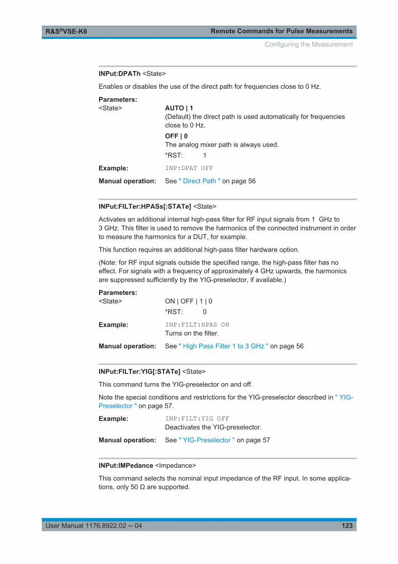
Remote Commands for Pulse MeasurementsR&S®VSE-K6
123User Manual 1176.8922.02 ─ 04
INPut:DPATh <State>
Enables or disables the use of the direct path for frequencies close to 0 Hz.
Parameters:<State> AUTO | 1
(Default) the direct path is used automatically for frequenciesclose to 0 Hz.OFF | 0The analog mixer path is always used.*RST: 1
Example: INP:DPAT OFFManual operation: See " Direct Path " on page 56
INPut:FILTer:HPASs[:STATe] <State>
Activates an additional internal high-pass filter for RF input signals from 1 GHz to3 GHz. This filter is used to remove the harmonics of the connected instrument in orderto measure the harmonics for a DUT, for example.
This function requires an additional high-pass filter hardware option.
(Note: for RF input signals outside the specified range, the high-pass filter has noeffect. For signals with a frequency of approximately 4 GHz upwards, the harmonicsare suppressed sufficiently by the YIG-preselector, if available.)
Parameters:<State> ON | OFF | 1 | 0
*RST: 0
Example: INP:FILT:HPAS ONTurns on the filter.
Manual operation: See " High Pass Filter 1 to 3 GHz " on page 56
INPut:FILTer:YIG[:STATe] <State>
This command turns the YIG-preselector on and off.
Note the special conditions and restrictions for the YIG-preselector described in " YIG-Preselector " on page 57.
Example: INP:FILT:YIG OFFDeactivates the YIG-preselector.
Manual operation: See " YIG-Preselector " on page 57
INPut:IMPedance <Impedance>
This command selects the nominal input impedance of the RF input. In some applica-tions, only 50 Ω are supported.
Configuring the Measurement

Remote Commands for Pulse MeasurementsR&S®VSE-K6
124User Manual 1176.8922.02 ─ 04
Parameters:<Impedance> 50 | 75
*RST: 50 Ω
Example: INP:IMP 75Manual operation: See " Impedance " on page 59
INPut<n>:PRESelection:SET <Mode>
This command selects the preselector mode.
The command is available with the optional preselector.
Suffix: <n>
.irrelevant
Parameters:<Mode> NARRow
Performs a measurement by automatically applying all availablecombinations of low and high pass filters consecutively. Thesecombinations all have a narrow bandwidth.WIDEPerforms a measurement by automatically applying all availablebandpass filters consecutively. The bandpass filters have a widebandwidth.
Manual operation: See "Preselector Mode" on page 58
INPut<n>:PRESelection[:STATe] <State>
This command turns the preselector on and off.
Suffix: <n>
.irrelevant
Manual operation: See "Preselector State" on page 58
INPut:RF:CAPM <Mode>
Determines how data from an oscilloscope is input to the R&S VSE software.
This command is only available for connected oscilloscopes.
Configuring the Measurement

Remote Commands for Pulse MeasurementsR&S®VSE-K6
125User Manual 1176.8922.02 ─ 04
Parameters:<Mode> IQ
The measured waveform is converted to I/Q data directly on theR&S RTO (requires option R&S RTO-K11), and input to theR&S VSE software as I/Q data.WAVeformThe data is input in its original waveform format and convertedto I/Q data in the R&S VSE software. No additional options arerequired on the R&S RTO.AUTOUses "I/Q" mode when possible, and "Waveform" only whenrequired by the application (e.g. Pulse measurement).*RST: IQ
Example: INP:RF:CAPM WAVManual operation: See "Capture Mode" on page 57
INPut:SELect <Source>
This command selects the signal source for measurements, i.e. it defines which con-nector is used to input data to the R&S VSE.
Parameters:<Source> RF
Radio Frequency ("RF INPUT" connector)FIQI/Q data file*RST: RF
Manual operation: See "Input Type" on page 56
INPut<n>:TYPE <Input>
The command selects the signal source.
Suffix: <n>
.irrelevant
Parameters:<Input> INPUT1
Selects RF input 1.INPUT2Selects RF input 2.*RST: INPUT1
Example: INP:TYPE INPUT1Selects RF input 1.
Manual operation: See "Input Selection" on page 59
Configuring the Measurement

Remote Commands for Pulse MeasurementsR&S®VSE-K6
126User Manual 1176.8922.02 ─ 04
INSTrument:BLOCk:CHANnel[:SETTings]:SOURce <Type>
Selects an instrument or a file as the source of input provided to the channel.
Parameters:<Type> FILE | DEVice | NONE
FILEA loaded file is used for input.DEViceA configured device provides input for the measurementNONENo input source defined.
Manual operation: See "Input Type" on page 56
SYSTem:COMMunicate:RDEVice:OSCilloscope[:STATe] <State>
Activates the optional 2 GHz bandwidth extension (R&S FSW-B2000).
Note: Manual operation on the connected oscilloscope, or remote operation other thanby the R&S VSE, is not possible while the B2000 option is active.
Parameters:<State> ON | OFF | 1 | 0
ON | 1Option is active.OFF | 0Option is disabled.*RST: 0
Example: SYST:COMM:RDEV:OSC ONManual operation: See "B2000 State" on page 57
SYSTem:COMMunicate:RDEVice:OSCilloscope:TCPip <Address>
Defines the TCPIP address or computer name of the oscilloscope connected to theR&S VSE via LAN.
Note: The IP address is maintained after a PRESET, and is transferred between appli-cations.
Parameters:<Address> computer name or IP address
Example: SYST:COMM:RDEV:OSC:TCP '192.0.2.0'Example: SYST:COMM:RDEV:OSC:TCP 'FSW43-12345'Manual operation: See "RTO IP Address" on page 58
Configuring the Measurement

Remote Commands for Pulse MeasurementsR&S®VSE-K6
127User Manual 1176.8922.02 ─ 04
SYSTem:COMMunicate:RDEVice:OSCilloscope:PSMode[:STATe] <State>
Activates the use of the power splitter inserted between the IF 2 GHZ OUT connectorof the R&S VSE and the CH1 and CH3 input connectors of the oscilloscope. Note thatthis mode requires an additional alignment with the power splitter.
For details see the R&S FSW I/Q Analyzer and I/Q Input User Manual
Parameters:<State> ON | OFF | 1 | 0
ON | 1Mode is active.OFF | 0Mode is disabled.*RST: 0
Example: SYST:COMM:RDEV:OSC:PSM ONManual operation: See "RTO Splitter Mode" on page 58
SYSTem:COMMunicate:RDEVice:OSCilloscope:SRATe <Rate>
Determines whether the 10 GHz mode (default) or 20 GHz mode of the connectedoscilloscope is used. The 20 GHZ mode achieves a higher decimation gain, butreduces the record length by half.
Return values: <Rate> 10 GHz | 20 GHz
No other sample rate values are allowed.*RST: 10 GHz
Example: TRAC:IQ:SRAT?//Result: 100000000TRAC:IQ:RLEN?//Result: 3128SYST:COMM:RDEV:OSC:SRAT 20GHZTRAC:IQ:SRAT?//Result: 200000000TRAC:IQ:RLEN?//Result: 1564
Manual operation: See "RTO Sample Rate" on page 58
SYSTem:COMMunicate:RDEVice:OSCilloscope:VDEVice?
Queries whether the connected instrument is supported by the 2 GHz bandwidthextension option(R&S VSE-B2000).
Configuring the Measurement

Remote Commands for Pulse MeasurementsR&S®VSE-K6
128User Manual 1176.8922.02 ─ 04
Return values: <State> ON | 1
Instrument is supportedOFF | 0Instrument is not supported
Example: SYST:COMM:RDEV:OSC:VDEV?Usage: Query only
SYSTem:COMMunicate:RDEVice:OSCilloscope:VFIRmware?
Queries whether the firmware on the connected oscilloscope is supported by the2 GHz bandwidth extension (R&S VSE-B2000) option.
Return values: <State> ON | 1
Firmware is supportedOFF | 0Firmware is not supported
Example: SYST:COMM:RDEV:OSC:VFIR?Usage: Query only
8.4.4 Frontend Configuration
The following commands are required to configure frequency and amplitude settings,which represent the "frontend" of the measurement setup.
● Frequency............................................................................................................. 128● Amplitude Settings................................................................................................ 130● Configuring the Attenuation...................................................................................132
8.4.4.1 Frequency
[SENSe:]FREQuency:CENTer.........................................................................................128[SENSe:]FREQuency:CENTer:STEP............................................................................... 129[SENSe:]FREQuency:CENTer:STEP:AUTO..................................................................... 129[SENSe:]FREQuency:OFFSet......................................................................................... 130
[SENSe:]FREQuency:CENTer <Frequency>
This command defines the center frequency.
Configuring the Measurement

Remote Commands for Pulse MeasurementsR&S®VSE-K6
129User Manual 1176.8922.02 ─ 04
Parameters:<Frequency> The allowed range and fmax is specified in the data sheet.
UPIncreases the center frequency by the step defined using the[SENSe:]FREQuency:CENTer:STEP command.
DOWNDecreases the center frequency by the step defined using the[SENSe:]FREQuency:CENTer:STEP command.
*RST: fmax/2Default unit: Hz
Example: FREQ:CENT 100 MHzFREQ:CENT:STEP 10 MHzFREQ:CENT UPSets the center frequency to 110 MHz.
Manual operation: See " Center Frequency " on page 61
[SENSe:]FREQuency:CENTer:STEP <StepSize>
This command defines the center frequency step size.
You can increase or decrease the center frequency quickly in fixed steps using theSENS:FREQ UP AND SENS:FREQ DOWN commands, see [SENSe:]FREQuency:CENTer on page 128.
Parameters:<StepSize> fmax is specified in the data sheet.
Range: 1 to fMAX*RST: 0.1 x spanDefault unit: Hz
Example: //Set the center frequency to 110 MHz.FREQ:CENT 100 MHzFREQ:CENT:STEP 10 MHzFREQ:CENT UP
Manual operation: See " Center Frequency Stepsize " on page 61
[SENSe:]FREQuency:CENTer:STEP:AUTO <State>
This command couples or decouples the center frequency step size to the span.
Parameters:<State> ON | OFF | 0 | 1
*RST: 1
Example: FREQ:CENT:STEP:AUTO ONActivates the coupling of the step size to the span.
Configuring the Measurement

Remote Commands for Pulse MeasurementsR&S®VSE-K6
130User Manual 1176.8922.02 ─ 04
[SENSe:]FREQuency:OFFSet <Offset>
This command defines a frequency offset.
If this value is not 0 Hz, the application assumes that the input signal was frequencyshifted outside the application. All results of type "frequency" will be corrected for thisshift numerically by the application.
See also " Frequency Offset " on page 62.
Parameters:<Offset> Range: -100 GHz to 100 GHz
*RST: 0 Hz
Example: FREQ:OFFS 1GHZManual operation: See " Frequency Offset " on page 62
8.4.4.2 Amplitude Settings
The following commands are required to configure the amplitude settings in a remoteenvironment.
Useful commands for amplitude settings described elsewhere:● INPut:COUPling on page 122● INPut:IMPedance on page 123● DISPlay[:WINDow<n>]:TRACe<t>:Y[:SCALe]:AUTO on page 232
Remote commands exclusive to amplitude settings:
DISPlay[:WINDow<n>]:TRACe<t>:Y[:SCALe]:RLEVel....................................................... 130DISPlay[:WINDow<n>]:TRACe<t>:Y[:SCALe]:RLEVel:OFFSet........................................... 131INPut:GAIN:STATe........................................................................................................ 131INPut:GAIN[:VALue].......................................................................................................131
DISPlay[:WINDow<n>]:TRACe<t>:Y[:SCALe]:RLEVel <ReferenceLevel>
This command defines the reference level (for all traces in all windows).
With a reference level offset ≠ 0, the value range of the reference level is modified bythe offset.
Suffix: <n>, <t>
.irrelevant
Parameters:<ReferenceLevel> The unit is variable.
Range: see datasheet*RST: 0 dBm
Example: DISP:TRAC:Y:RLEV -60dBmManual operation: See " Reference Level " on page 63
Configuring the Measurement

Remote Commands for Pulse MeasurementsR&S®VSE-K6
131User Manual 1176.8922.02 ─ 04
DISPlay[:WINDow<n>]:TRACe<t>:Y[:SCALe]:RLEVel:OFFSet <Offset>
This command defines a reference level offset (for all traces in all windows).
Suffix: <n>, <t>
.irrelevant
Parameters:<Offset> Range: -200 dB to 200 dB
*RST: 0dB
Example: DISP:TRAC:Y:RLEV:OFFS -10dBManual operation: See " Shifting the Display ( Offset )" on page 63
INPut:GAIN:STATe <State>
This command turns the preamplifier on the connected instrument on and off. Itrequires the additional preamplifier hardware option on the connected instrument.
Depending on the connected instrument, the preamplification is defined by INPut:GAIN[:VALue].
Parameters:<State> ON | OFF | 1 | 0
*RST: 0
Example: INP:GAIN:STAT ONSwitches on 30 dB preamplification.
Manual operation: See " Preamplifier " on page 64
INPut:GAIN[:VALue] <Gain>
This command selects the gain if the preamplifier is activated (INP:GAIN:STAT ON,see INPut:GAIN:STATe on page 131).
The command requires the additional preamplifier hardware option.
Parameters:<Gain> 15 dB | 30 dB
The availability of gain levels depends on the model of the con-nected instrument.*RST: OFF
Example: INP:GAIN:STAT ONINP:GAIN:VAL 30Switches on 30 dB preamplification.
Manual operation: See " Preamplifier " on page 64
Configuring the Measurement

Remote Commands for Pulse MeasurementsR&S®VSE-K6
132User Manual 1176.8922.02 ─ 04
8.4.4.3 Configuring the Attenuation
INPut:ATTenuation.........................................................................................................132INPut:ATTenuation:AUTO...............................................................................................132INPut:EATT...................................................................................................................132INPut:EATT:AUTO......................................................................................................... 133INPut:EATT:STATe........................................................................................................133
INPut:ATTenuation <Attenuation>
This command defines the total attenuation for RF input.
If you set the attenuation manually, it is no longer coupled to the reference level, butthe reference level is coupled to the attenuation. Thus, if the current reference level isnot compatible with an attenuation that has been set manually, the command alsoadjusts the reference level.
Parameters:<Attenuation> Range: see data sheet
Increment: 5 dB*RST: 10 dB (AUTO is set to ON)
Example: INP:ATT 30dBDefines a 30 dB attenuation and decouples the attenuation fromthe reference level.
Manual operation: See " Attenuation Mode / Value " on page 63
INPut:ATTenuation:AUTO <State>
This command couples or decouples the attenuation to the reference level. Thus, whenthe reference level is changed, the R&S VSE determines the signal level for optimalinternal data processing and sets the required attenuation accordingly.
Parameters:<State> ON | OFF | 0 | 1
*RST: 1
Example: INP:ATT:AUTO ONCouples the attenuation to the reference level.
Manual operation: See " Attenuation Mode / Value " on page 63
INPut:EATT <Attenuation>
This command defines an electronic attenuation manually. Automatic mode must beswitched off (INP:EATT:AUTO OFF, see INPut:EATT:AUTO on page 133).
If the current reference level is not compatible with an attenuation that has been setmanually, the command also adjusts the reference level.
Configuring the Measurement

Remote Commands for Pulse MeasurementsR&S®VSE-K6
133User Manual 1176.8922.02 ─ 04
Parameters:<Attenuation> attenuation in dB
Range: see data sheetIncrement: 1 dB*RST: 0 dB (OFF)
Example: INP:EATT:AUTO OFFINP:EATT 10 dB
Manual operation: See " Using Electronic Attenuation " on page 64
INPut:EATT:AUTO <State>
This command turns automatic selection of the electronic attenuation on and off.
If on, electronic attenuation reduces the mechanical attenuation whenever possible.
Parameters:<State> 1 | 0 | ON | OFF
1 | ON0 | OFF*RST: 1
Example: INP:EATT:AUTO OFFManual operation: See " Using Electronic Attenuation " on page 64
INPut:EATT:STATe <State>
This command turns the electronic attenuator on and off.
Parameters:<State> 1 | 0 | ON | OFF
1 | ON0 | OFF*RST: 0
Example: INP:EATT:STAT ONSwitches the electronic attenuator into the signal path.
Manual operation: See " Using Electronic Attenuation " on page 64
8.4.5 Triggering Measurements
Useful commands for triggering described elsewhere:● [SENSe:]FREQuency:CENTer on page 128
Remote commands exclusive to triggering:
● Configuring the Triggering Conditions...................................................................134● Configuring the Trigger Output..............................................................................140
Configuring the Measurement

Remote Commands for Pulse MeasurementsR&S®VSE-K6
134User Manual 1176.8922.02 ─ 04
8.4.5.1 Configuring the Triggering Conditions
The following commands are required to configure triggered measurements.
Note that the availability of trigger settings depends on the connected instrument.
TRIGger[:SEQuence]:DTIMe...........................................................................................134TRIGger[:SEQuence]:HOLDoff[:TIME]..............................................................................134TRIGger[:SEQuence]:IFPower:HOLDoff........................................................................... 135TRIGger[:SEQuence]:IFPower:HYSTeresis...................................................................... 135TRIGger[:SEQuence]:LEVel[:EXTernal<port>].................................................................. 135TRIGger[:SEQuence]:LEVel:IFPower...............................................................................136TRIGger[:SEQuence]:LEVel:IQPower.............................................................................. 136TRIGger[:SEQuence]:LEVel:MAPower.............................................................................136TRIGger[:SEQuence]:MAPower:HOLDoff......................................................................... 136TRIGger[:SEQuence]:MAPower:HYSTeresis.................................................................... 137TRIGger[:SEQuence]:LEVel:RFPower..............................................................................137TRIGger[:SEQuence]:RFPower:HOLDoff..........................................................................137TRIGger[:SEQuence]:SLOPe.......................................................................................... 138TRIGger[:SEQuence]:SOURce........................................................................................138TRIGger[:SEQuence]:TIME:RINTerval............................................................................. 140
TRIGger[:SEQuence]:DTIMe <DropoutTime>
Defines the time the input signal must stay below the trigger level before a trigger isdetected again.
Parameters:<DropoutTime> Dropout time of the trigger.
Range: 0 s to 10.0 s*RST: 0 s
Manual operation: See " Drop-Out Time " on page 67
TRIGger[:SEQuence]:HOLDoff[:TIME] <Offset>
Defines the time offset between the trigger event and the start of the measurement.
A negative offset is possible for time domain measurements.
Parameters:<Offset> For measurements in the frequency domain, the range is 0 s to
30 s.For measurements in the time domain, the range is the negativemeasurement time to 30 s.*RST: 0 s
Example: TRIG:HOLD 500usManual operation: See " Trigger Offset " on page 67
Configuring the Measurement

Remote Commands for Pulse MeasurementsR&S®VSE-K6
135User Manual 1176.8922.02 ─ 04
TRIGger[:SEQuence]:IFPower:HOLDoff <Period>
This command defines the holding time before the next trigger event.
Note that this command can be used for any trigger source, not just IF Power(despite the legacy keyword).
Parameters:<Period> Range: 0 s to 10 s
*RST: 0 s
Example: TRIG:SOUR EXTSets an external trigger source.TRIG:IFP:HOLD 200 nsSets the holding time to 200 ns.
Manual operation: See " Trigger Holdoff " on page 68
TRIGger[:SEQuence]:IFPower:HYSTeresis <Hysteresis>
This command defines the trigger hysteresis, which is only available for "IF Power" trig-ger sources.
Parameters:<Hysteresis> Range: 3 dB to 50 dB
*RST: 3 dB
Example: TRIG:SOUR IFPSets the IF power trigger source.TRIG:IFP:HYST 10DBSets the hysteresis limit value.
Manual operation: See " Hysteresis " on page 68
TRIGger[:SEQuence]:LEVel[:EXTernal<port>] <TriggerLevel>
This command defines the level the external signal must exceed to cause a triggerevent.
Suffix: <port>
.Selects the trigger port.1 = trigger port 1 (TRIGGER INPUT connector on front panel)2 = trigger port 2 (TRIGGER INPUT/OUTPUT connector on frontpanel)3 = trigger port 3 (TRIGGER3 INPUT/OUTPUT connector onrear panel)
Parameters:<TriggerLevel> Range: 0.5 V to 3.5 V
*RST: 1.4 V
Example: TRIG:LEV 2VManual operation: See " Trigger Level " on page 67
Configuring the Measurement

Remote Commands for Pulse MeasurementsR&S®VSE-K6
136User Manual 1176.8922.02 ─ 04
TRIGger[:SEQuence]:LEVel:IFPower <TriggerLevel>
This command defines the power level at the third intermediate frequency that must beexceeded to cause a trigger event. Note that any RF attenuation or preamplification isconsidered when the trigger level is analyzed. If defined, a reference level offset is alsoconsidered.
Parameters:<TriggerLevel> For details on available trigger levels and trigger bandwidths see
the data sheet.*RST: -10 dBm
Example: TRIG:LEV:IFP -30DBMManual operation: See " Trigger Level " on page 67
TRIGger[:SEQuence]:LEVel:IQPower <TriggerLevel>
This command defines the magnitude the I/Q data must exceed to cause a triggerevent. Note that any RF attenuation or preamplification is considered when the triggerlevel is analyzed.
Parameters:<TriggerLevel> Range: -130 dBm to 30 dBm
*RST: -20 dBm
Example: TRIG:LEV:IQP -30DBMManual operation: See " Trigger Level " on page 67
TRIGger[:SEQuence]:LEVel:MAPower <TriggerLevel>
This command defines the power level that must be exceeded to cause a trigger eventfor (offline) input from a file.
Parameters:<TriggerLevel> For details on available trigger levels and trigger bandwidths see
the data sheet.
Example: TRIG:LEV:MAP -30DBM
TRIGger[:SEQuence]:MAPower:HOLDoff <Period>
This command defines the holding time before the next trigger event for (offline) inputfrom a file.
Parameters:<Period> Range: 0 s to 10 s
*RST: 0 s
Configuring the Measurement

Remote Commands for Pulse MeasurementsR&S®VSE-K6
137User Manual 1176.8922.02 ─ 04
Example: TRIG:SOUR MAGNSets an offline magnitude trigger source.TRIG:MAP:HOLD 200 nsSets the holding time to 200 ns.
Manual operation: See " Trigger Holdoff " on page 68
TRIGger[:SEQuence]:MAPower:HYSTeresis <Hysteresis>
This command defines the trigger hysteresis for the (offline) magnitude trigger source(used for input from a file).
Parameters:<Hysteresis> Range: 3 dB to 50 dB
*RST: 3 dB
Example: TRIG:SOUR MAPSets the (offline) magnitude trigger source.TRIG:MAP:HYST 10DBSets the hysteresis limit value.
Manual operation: See " Hysteresis " on page 68
TRIGger[:SEQuence]:LEVel:RFPower <TriggerLevel>
This command defines the power level the RF input must exceed to cause a triggerevent. Note that any RF attenuation or preamplification is considered when the triggerlevel is analyzed. If defined, a reference level offset is also considered.
The input signal must be between 500 MHz and 8 GHz.
Parameters:<TriggerLevel> For details on available trigger levels and trigger bandwidths see
the data sheet.*RST: -20 dBm
Example: TRIG:LEV:RFP -30dBmManual operation: See " Trigger Level " on page 67
TRIGger[:SEQuence]:RFPower:HOLDoff <Time>
This command defines the holding time before the next trigger event. Note that thiscommand is available for any trigger source, not just RF Power.
Note that this command is maintained for compatibility reasons only. Use theTRIGger[:SEQuence]:IFPower:HOLDoff on page 135 command for new remotecontrol programs.
Parameters:<Time> Default unit: S
Configuring the Measurement

Remote Commands for Pulse MeasurementsR&S®VSE-K6
138User Manual 1176.8922.02 ─ 04
TRIGger[:SEQuence]:SLOPe <Type>
Parameters:<Type> POSitive | NEGative
POSitiveTriggers when the signal rises to the trigger level (rising edge).NEGativeTriggers when the signal drops to the trigger level (falling edge).*RST: POSitive
Example: TRIG:SLOP NEGManual operation: See " Slope " on page 67
TRIGger[:SEQuence]:SOURce <Source>
This command selects the trigger source.
Note that the availability of trigger sources depends on the connected instrument.
Note on external triggers:
If a measurement is configured to wait for an external trigger signal in a remote controlprogram, remote control is blocked until the trigger is received and the program cancontinue. Make sure this situation is avoided in your remote control programs.
Configuring the Measurement

Remote Commands for Pulse MeasurementsR&S®VSE-K6
139User Manual 1176.8922.02 ─ 04
Parameters:<Source> IMMediate
Free RunEXTernalTrigger signal from the TRIGGER INPUT connector.If the optional 2 GHz bandwidth extension (R&S VSE-B2000) isinstalled and active, this parameter activates the CH3 input con-nector on the oscilloscope. Then the R&S VSE triggers when thesignal fed into the CH3 input connector on the oscilloscopemeets or exceeds the specified trigger level.Note: In previous firmware versions, the external trigger wasconnected to the CH2 input on the oscilloscope. As of firmwareversion R&S VSE 2.30, the CH3 input on the oscilloscope mustbe used!If power splitter mode is active, this parameter activates the EXTTRIGGER INPUT connector on the oscilloscope. Then theR&S VSE triggers when the signal fed into the EXT TRIGGERINPUT connector on the oscilloscope meets or exceeds thespecified trigger level.EXT | EXT2 | EXT3 | EXT4Trigger signal from the corresponding TRIGGER INPUT/OUTPUT connector on the connected instrument, or the oscillo-scope's corresponding input channel.For details on the connectors see the instrument's Getting Star-ted manual.RFPowerFirst intermediate frequencyIFPowerSecond intermediate frequencyIQPowerMagnitude of sampled I/Q dataFor applications that process I/Q data, such as the I/Q Analyzeror optional applications.MAGNitudeFor (offline) input from a file, rather than an instrument.The trigger level is specified by TRIGger[:SEQuence]:LEVel:MAPower.
*RST: IMMediate
Example: TRIG:SOUR EXTSelects the external trigger input as source of the trigger signal
Manual operation: See "Trigger Source" on page 65See " Free Run " on page 65See " External Trigger<X> " on page 66See " I/Q Power " on page 66See " IF Power " on page 66See " RF Power " on page 66
Configuring the Measurement

Remote Commands for Pulse MeasurementsR&S®VSE-K6
140User Manual 1176.8922.02 ─ 04
TRIGger[:SEQuence]:TIME:RINTerval <Interval>
This command defines the repetition interval for the time trigger.
Parameters:<Interval> 2.0 ms to 5000
Range: 2 ms to 5000 s*RST: 1.0 s
Example: TRIG:SOUR TIMESelects the time trigger input for triggering.TRIG:TIME:RINT 50The measurement starts every 50 s.
8.4.5.2 Configuring the Trigger Output
The following commands are required to send the trigger signal to one of the variableTRIGGER INPUT/OUTPUT connectors on the connected instrument.
OUTPut:TRIGger<port>:DIRection...................................................................................140OUTPut:TRIGger<port>:LEVel........................................................................................ 140OUTPut:TRIGger<port>:OTYPe...................................................................................... 141OUTPut:TRIGger<port>:PULSe:IMMediate.......................................................................141OUTPut:TRIGger<port>:PULSe:LENGth.......................................................................... 141
OUTPut:TRIGger<port>:DIRection <Direction>
This command selects the trigger direction for trigger ports that serve as an input aswell as an output.
Suffix: <port>
.
Parameters:<Direction> INPut
Port works as an input.OUTPutPort works as an output.*RST: INPut
OUTPut:TRIGger<port>:LEVel <Level>
This command defines the level of the (TTL compatible) signal generated at the triggeroutput.
This command works only if you have selected a user defined output with OUTPut:TRIGger<port>:OTYPe.
Suffix: <port>
.Selects the trigger port to which the output is sent.
Configuring the Measurement

Remote Commands for Pulse MeasurementsR&S®VSE-K6
141User Manual 1176.8922.02 ─ 04
Parameters:<Level> HIGH
5 VLOW0 V*RST: LOW
Example: OUTP:TRIG2:LEV HIGH
OUTPut:TRIGger<port>:OTYPe <OutputType>
This command selects the type of signal generated at the trigger output.
Suffix: <port>
.Selects the trigger port to which the output is sent.
Parameters:<OutputType> DEVice
Sends a trigger signal when the R&S VSE has triggered inter-nally.TARMedSends a trigger signal when the trigger is armed and ready foran external trigger event.UDEFinedSends a user defined trigger signal. For more information seeOUTPut:TRIGger<port>:LEVel.
*RST: DEVice
OUTPut:TRIGger<port>:PULSe:IMMediate
This command generates a pulse at the trigger output.
Suffix: <port>
.Selects the trigger port to which the output is sent.
Usage: Event
OUTPut:TRIGger<port>:PULSe:LENGth <Length>
This command defines the length of the pulse generated at the trigger output.
Suffix: <port>
.Selects the trigger port to which the output is sent.
Parameters:<Length> Pulse length in seconds.
Example: OUTP:TRIG2:PULS:LENG 0.02
Configuring the Measurement

Remote Commands for Pulse MeasurementsR&S®VSE-K6
142User Manual 1176.8922.02 ─ 04
8.4.6 Data Acquisition
The following commands are required to configure how much and how data is capturedfrom the input signal.
[SENSe:]BANDwidth:DEMod...........................................................................................142[SENSe:]BWIDth:DEMod................................................................................................ 142[SENSe:]BANDwidth:DEMod:TYPE................................................................................. 142[SENSe:]BWIDth:DEMod:TYPE.......................................................................................142[SENSe:]DEMod:FMVF:TYPE......................................................................................... 143[SENSe:]SRATe?...........................................................................................................143[SENSe:]SWEep:TIME................................................................................................... 143
[SENSe:]BANDwidth:DEMod <Bandwidth>[SENSe:]BWIDth:DEMod <Bandwidth>
Sets/queries the measurement bandwidth in Hz.
The measurement bandwidth is defined by the used filter and the sample rate. Forinformation on supported sample rates and filter bandwidths see the data sheet.
Parameters:<Bandwidth> *RST: 80.0 MHz
Default unit: HZ
[SENSe:]BANDwidth:DEMod:TYPE <FilterType>[SENSe:]BWIDth:DEMod:TYPE <FilterType>
This command defines the type of demodulation filter to be used. For information onsupported filter bandwidths see the data sheet.
Parameters:<FilterType> FLAT | GAUSs
FLATStandard flat demodulation filterGAUSsGaussian filter for optimized settling behaviorFor Gaussian filters with a large 3dB bandwidth (> 40 MHz, onlyavailable with the bandwidth extension option) the actual filtershape deviates strongly from the ideal Gauss filter outside arange of approximately ±80 MHz. For this range the flat filter ismore accurate.For details see Chapter D, "Effects of Large Gauss Filters",on page 336.*RST: GAUS
Manual operation: See "Filter type" on page 69
Configuring the Measurement

Remote Commands for Pulse MeasurementsR&S®VSE-K6
143User Manual 1176.8922.02 ─ 04
[SENSe:]DEMod:FMVF:TYPE <Filter>
Activates or deactivates additional filters applied after demodulation to filter out unwan-ted signals, or correct pre-emphasized input signals.
Parameters:<Filter> NONE | LP01 | LP1 | LP5 | LP10 | LP25
NONENo video filter appliedLP01Low pass filter 0.1 % bandwidthLP1Low pass filter1 % bandwidthLP5Low pass filter 5 % bandwidthLP10Low pass filter 10 % bandwidthLP25Low pass filter 25 % bandwidth
Example: SENS:DEM:FMVF:TYPE LP01Manual operation: See "FM Video Bandwidth" on page 82
[SENSe:]SRATe?
This command returns the sample rate set up for current measurement settings.
Return values: <SampleRate> Current sample rate used by the application.
Usage: Query only
[SENSe:]SWEep:TIME <Time>
This command defines the measurement time.
The maximum measurement time in the R&S VSE Pulse application is limited only bythe available memory ("memory limit reached" message is shown in status bar). Note,however, that increasing the measurement time (and thus reducing the available mem-ory space) may restrict the number of measurement channels that can be activatedsimultaneously on the R&S VSE.
Parameters:<Time> refer to data sheet
*RST: depends on current settings (determined automati-cally)
Example: SWE:TIME 10sManual operation: See "Measurement Time" on page 69
Configuring the Measurement

Remote Commands for Pulse MeasurementsR&S®VSE-K6
144User Manual 1176.8922.02 ─ 04
8.4.7 Pulse Detection
The pulse detection settings define the conditions under which a pulse is detectedwithin the input signal.
[SENSe:]DETect:LIMit.................................................................................................... 144[SENSe:]DETect:LIMit:COUNt.........................................................................................144[SENSe:]DETect:HYSTeresis..........................................................................................144[SENSe:]DETect:REFerence...........................................................................................145[SENSe:]DETect:THReshold........................................................................................... 145
[SENSe:]DETect:LIMit <State>
If enabled, the number of pulses to be detected is restricted. When the maximum num-ber is exceeded, measurement is stopped for the current capture buffer. This limitationcan be used to speed up the measurement if only a small number of pulses is of inter-est.
The maximum number of pulses to be detected is defined using the [SENSe:]DETect:LIMit:COUNt command.
Parameters:<State> ON | OFF | 0 | 1
OFF | 0Switches the function offON | 1Switches the function on*RST: 0
Manual operation: See "Detection Limit" on page 71
[SENSe:]DETect:LIMit:COUNt <MaxPulseCount>
Defines the maximum number of pulses to be detected.
This limit is only considered if [SENSe:]DETect:LIMit is enabled.
Parameters:<MaxPulseCount> integer
*RST: 1000
Manual operation: See "Maximum Pulse Count" on page 71
[SENSe:]DETect:HYSTeresis <Hysteresis>
Defines a hysteresis for pulse detection in dB in relation to the defined threshold (see[SENSe:]DETect:THReshold on page 145). As long as the signal does not exceedthe hysteresis, the next threshold crossing is ignored.
Parameters:<Hysteresis> *RST: 0
Default unit: DB
Configuring the Measurement

Remote Commands for Pulse MeasurementsR&S®VSE-K6
145User Manual 1176.8922.02 ─ 04
Manual operation: See "Hysteresis" on page 71
[SENSe:]DETect:REFerence <Reference>
The reference level to be used for setting the pulse detection threshold.
Parameters:<Reference> REFLevel | PEAK | NOISe | ABSolute
REFLevelCurrent reference levelPEAKPeak level as measured over the entire capture data intervalNOISeNoise level determined from the current capture data accordingto SENSe:TRACe:MEASurement:DEFine:DURation:MINon page 119.ABSoluteAbsolute level defined by [SENSe:]DETect:THResholdon page 145.*RST: PEAK
Manual operation: See "Reference Source" on page 70
[SENSe:]DETect:THReshold <Level>
The threshold determines whether a pulse is detected or not. The top of a pulse mustexceed the threshold in order to be detected. The threshold is defined in relation to thereference defined by [SENSe:]DETect:REFerence.
Parameters:<Level> numeric value in dB or dBm, depending on reference type
*RST: -10.0
Manual operation: See "Threshold" on page 71
8.4.8 Configuring the Pulse Measurement
The following commands determine how much data is measured for each pulse, inrelation to defined levels, points, or ranges.
● Measurement Levels.............................................................................................146● Measurement Point...............................................................................................148● Measurement Range.............................................................................................150
Configuring the Measurement

Remote Commands for Pulse MeasurementsR&S®VSE-K6
146User Manual 1176.8922.02 ─ 04
8.4.8.1 Measurement Levels
SENSe:TRACe:MEASurement:ALGorithm........................................................................146SENSe:TRACe:MEASurement:DEFine:AMPLitude:UNIT................................................... 146SENSe:TRACe:MEASurement:DEFine:BOUNdary:TOP.................................................... 146SENSe:TRACe:MEASurement:DEFine:COMPensate:ADRoop...........................................147SENSe:TRACe:MEASurement:DEFine:RIPPle................................................................. 147SENSe:TRACe:MEASurement:DEFine:TRANsition:HREFerence........................................147SENSe:TRACe:MEASurement:DEFine:TRANsition:LREFerence........................................ 147SENSe:TRACe:MEASurement:DEFine:TRANsition:REFerence..........................................148
SENSe:TRACe:MEASurement:ALGorithm <Algorithm>
The measurement algorithm used for finding the pulse top and base levels.
Parameters:<Algorithm> MEAN
The arithmetic average of the measured valuesMEDianThe level for which half the values lie above, the other half belowin the histogramPEAKpowerThe peak power is used to detect the pulse top level.*RST: MEDian
Manual operation: See "Measurement Algorithm" on page 73
SENSe:TRACe:MEASurement:DEFine:AMPLitude:UNIT <Unit>
Defines the unit of the pulse amplitude values, i.e. whether magnitude (V) or power (W,dBm) values are used to determine the threshold levels for fall and rise times.
Parameters:<Unit> V | W | DBM
*RST: V
Manual operation: See "Reference Level Unit" on page 73
SENSe:TRACe:MEASurement:DEFine:BOUNdary:TOP <PulseInstant>
The boundary in percent of the pulse amplitude to either side of the pulse top (ONstate). Used to determine the settling time, for example. Once the signal remains withinthe boundary, it is assumed to have settled.
Parameters:<PulseInstant> percentage
Range: 1 to 20*RST: 3
Manual operation: See "Boundary" on page 74
Configuring the Measurement

Remote Commands for Pulse MeasurementsR&S®VSE-K6
147User Manual 1176.8922.02 ─ 04
SENSe:TRACe:MEASurement:DEFine:COMPensate:ADRoop <State>
Determines whether the 100% value (from base to top) for the rise and fall time mea-surements is calculated from the Edges.
This allows you to consider a "droop" in the pulse top during the pulse measurements.If a droop is to be considered, the 100% value must be calculated separately for therising and falling edges.
Parameters:<State> ON | 1
The 100% value is measured separately for the rising and fallingedges.OFF | 0The 100% value is measured at the pulse center and used for allmeasurements.*RST: 1
Manual operation: See "Position" on page 72
SENSe:TRACe:MEASurement:DEFine:RIPPle <Portion>
Determines portion of the pulse top which is used to measure the ripple.
Parameters:<Portion> percentage
Range: 0 to 100*RST: 50
Manual operation: See "Ripple Portion" on page 73
SENSe:TRACe:MEASurement:DEFine:TRANsition:HREFerence <QueryRange>
The upper threshold in percent of the pulse amplitude used to signify the end of a ris-ing or beginning of a falling signal level.
Parameters:<QueryRange> percentage
Range: 0 to 100*RST: 90
Manual operation: See "High (Distal) Threshold" on page 73
SENSe:TRACe:MEASurement:DEFine:TRANsition:LREFerence <QueryRange>
The lower threshold in percent of the pulse amplitude used to signify the end of a fall-ing or beginning of a rising signal level.
Configuring the Measurement

Remote Commands for Pulse MeasurementsR&S®VSE-K6
148User Manual 1176.8922.02 ─ 04
Parameters:<QueryRange> percentage
Range: 0 to 100*RST: 10
Manual operation: See "Low (Proximal) Threshold" on page 73
SENSe:TRACe:MEASurement:DEFine:TRANsition:REFerence <QueryRange>
The threshold in percent of the pulse amplitude used to signify the mid-transition levelbetween pulse states.
Parameters:<QueryRange> percentage
Range: 0 to 100*RST: 50
Manual operation: See "Mid (Mesial) Threshold" on page 73
8.4.8.2 Measurement Point
SENSe:TRACe:MEASurement:DEFine:PULSe:INSTant.................................................... 148SENSe:TRACe:MEASurement:DEFine:PULSe:INSTant:AWINdow..................................... 148SENSe:TRACe:MEASurement:DEFine:PULSe:INSTant:REFerence................................... 149SENSe:TRACe:MEASurement:DEFine:PULSe:REFerence................................................ 149SENSe:TRACe:MEASurement:DEFine:PULSe:REFerence:POSition.................................. 149
SENSe:TRACe:MEASurement:DEFine:PULSe:INSTant <PulseInstant>
The time instant used for in-pulse measurements e.g. power, phase or frequency.
Parameters:<PulseInstant> *RST: 0
Default unit: S
Manual operation: See "Offset" on page 75
SENSe:TRACe:MEASurement:DEFine:PULSe:INSTant:AWINdow <PulseInstant>
The length of an averaging window centered on the Measurement Point.
Parameters:<PulseInstant> Size of the window around the measurement point used for
averagingRange: 0 to 10000*RST: 0.0Default unit: s
Manual operation: See "Averaging Window" on page 75
Configuring the Measurement

Remote Commands for Pulse MeasurementsR&S®VSE-K6
149User Manual 1176.8922.02 ─ 04
SENSe:TRACe:MEASurement:DEFine:PULSe:INSTant:REFerence <Reference>
The reference point used for specifying the pulse time instant.
Parameters:<Reference> RISE | CENTer | FALL
RISEThe measurement point is defined in reference to the rising edge(mid-level crossing).CENTerThe measurement point is defined in reference to the center ofthe pulse (equal distance from the rising and falling mid-levelcrossings).FALLThe measurement point is defined in reference to the fallingedge (mid-level crossing).*RST: CENTer
Manual operation: See "Measurement Point Reference" on page 74
SENSe:TRACe:MEASurement:DEFine:PULSe:REFerence <PulseNumber>
Selects a particular pulse to be used as a reference for relative pulse parameters (seeSENSe:TRACe:MEASurement:DEFine:PULSe:REFerence:POSitionon page 149).
The number of the current or all detected pulses can be queried using [SENSe:]PULSe:NUMBer? on page 256 or [SENSe:]PULSe:ID? on page 256.
Parameters:<PulseNumber> Range: 0 to number of detected pulses
*RST: 0
Manual operation: See "Reference for Pulse-Pulse Measurements" on page 75
SENSe:TRACe:MEASurement:DEFine:PULSe:REFerence:POSition <Mode>
Defines the eference pulse on which relative pulse results are based (e.g. for tracesnormalized to reference pulse, see Chapter 4.4.2, "Normalizing Traces", on page 45).
Configuring the Measurement

Remote Commands for Pulse MeasurementsR&S®VSE-K6
150User Manual 1176.8922.02 ─ 04
Parameters:<Mode> FIXed
A fixed pulse number; the pulse number is specified by SENSe:TRACe:MEASurement:DEFine:PULSe:REFerenceon page 149SELectedThe currently selected pulse (see SENSe:TRACe:MEASurement:DEFine:PULSe:SELected on page 162)
BPULseThe nth pulse before the currently evaluated pulse, where n isthe number specified by SENSe:TRACe:MEASurement:DEFine:PULSe:REFerence on page 149.No values are available for the first n pulses.APULseThe nth pulse after the currently evaluated pulse, where n is thenumber specified by SENSe:TRACe:MEASurement:DEFine:PULSe:REFerence on page 149.No values are available for the last n pulses.
Example: SENS:TRAC:MEAS:DEF:PULS:REF:POS FIXSENS:TRAC:MEAS:DEF:PULS:REF 1All relative pulse results are based on pulse number 1.
Example: SENS:TRAC:MEAS:DEF:PULS:SEL 2SENS:TRAC:MEAS:DEF:PULS:REF:POS SELAll relative pulse results are based on the currently selectedpulse number 2.
Example: SENS:TRAC:MEAS:DEF:PULS:REF:POS BPULSENS:TRAC:MEAS:DEF:PULS:REF 1For each pulse evaluation, the previous pulse is used as a refer-ence. The first pulse has no results.
Example: SENS:TRAC:MEAS:DEF:PULS:REF:POS APULSENS:TRAC:MEAS:DEF:PULS:REF 2For each pulse evaluation, the second-next pulse is used as areference. The last 2 pulses have no results.
Manual operation: See "Reference for Pulse-Pulse Measurements" on page 75
8.4.8.3 Measurement Range
SENSe:TRACe:MEASurement:DEFine:PULSe:ESTimation:LENGth................................... 150SENSe:TRACe:MEASurement:DEFine:PULSe:ESTimation:OFFSet:LEFT...........................151SENSe:TRACe:MEASurement:DEFine:PULSe:ESTimation:OFFSet:RIGHt......................... 151SENSe:TRACe:MEASurement:DEFine:PULSe:ESTimation:REFerence.............................. 151
SENSe:TRACe:MEASurement:DEFine:PULSe:ESTimation:LENGth <Length>
The estimation range length as a percentage of the pulse top length.
Configuring the Measurement

Remote Commands for Pulse MeasurementsR&S®VSE-K6
151User Manual 1176.8922.02 ─ 04
Parameters:<Length> percentage
Range: 1 to 100*RST: 75
Manual operation: See "Reference, Length, Offset" on page 76
SENSe:TRACe:MEASurement:DEFine:PULSe:ESTimation:OFFSet:LEFT<OffsetLeft>
The offset in seconds from the pulse rising edge at which the estimation range begins.
Parameters:<OffsetLeft> *RST: 0
Default unit: S
Manual operation: See "Reference, Length, Offset" on page 76
SENSe:TRACe:MEASurement:DEFine:PULSe:ESTimation:OFFSet:RIGHt<OffsetRight>
The offset in seconds from the pulse falling edge at which the estimation range ends.
Parameters:<OffsetRight> *RST: 0
Default unit: S
Manual operation: See "Reference, Length, Offset" on page 76
SENSe:TRACe:MEASurement:DEFine:PULSe:ESTimation:REFerence<Reference>
Defines the reference for the measurement range definition. Depending on theselected reference type, an additional setting is available to define the range.
Parameters:<Reference> CENTer | EDGE
CENTerDefines a relative range around the center of the pulse. Therange is defined by its length in percent of the pulse top.EDGEDefines the start and stop of the measurement range withrespect to the pulse edges. The range is defined by a time off-set from the middle of the rising edge and a time offset from themiddle of the falling edge.*RST: CENTer
Manual operation: See "Reference, Length, Offset" on page 76
Configuring the Measurement

Remote Commands for Pulse MeasurementsR&S®VSE-K6
152User Manual 1176.8922.02 ─ 04
8.4.9 Configuring the Result Display
The commands required to configure the screen display in a remote environment aredescribed here.
● Global Layout Commands.....................................................................................152● Working with Windows in the Display................................................................... 156● General Window Commands................................................................................ 161
8.4.9.1 Global Layout Commands
The following commands are required to change the evaluation type and rearrange thescreen layout across measurement channels as you do in manual operation.
For compatibility with other Rohde & Schwarz Signal and Spectrum Analyzers, the lay-out commands described in Chapter 8.4.9.2, "Working with Windows in the Display",on page 156 are also supported. Note, however, that the commands described thereonly allow you to configure the layout within the active measurement channel.
LAYout:GLOBal:ADD[:WINDow]?.................................................................................... 152LAYout:GLOBal:CATalog[:WINDow]?.............................................................................. 153LAYout:GLOBal:IDENtify[:WINDow]?............................................................................... 154LAYout:GLOBal:REMove[:WINDow]................................................................................ 155LAYout:GLOBal:REPLace[:WINDow]............................................................................... 155
LAYout:GLOBal:ADD[:WINDow]?<ExChanName>,<ExWinName>,<Direction>,<NewChanName>,<NewWinType>
This command adds a window to the display next to an existing window. The new win-dow may belong to a different channel than the existing window.
To replace an existing window, use the LAYout:GLOBal:REPLace[:WINDow] com-mand.
Parameters:<ExChanName> string
Name of an existing channel
<ExWinName> stringName of the existing window within the <ExChanName> chan-nel the new window is inserted next to.By default, the name of a window is the same as its index. Todetermine the name and index of all active windows use theLAYout:GLOBal:IDENtify[:WINDow]? query.
Configuring the Measurement

Remote Commands for Pulse MeasurementsR&S®VSE-K6
153User Manual 1176.8922.02 ─ 04
<Direction> LEFT | RIGHt | ABOVe | BELow | TABDirection the new window is added relative to the existing win-dow.TABThe new window is added as a new tab in the specified existingwindow.
<NewChanName> stringName of the channel for which a new window is to be added.
<NewWinType> stringType of result display (evaluation method) you want to add.See the table below for available parameter values.
Return values: <NewWindowName> When adding a new window, the command returns its name (by
default the same as its number) as a result.
Example: LAYout:GLOBal:ADD:WINDow? 'IQAnalyzer','1',RIGH,'IQ Analyzer2','FREQ'Adds a new window named 'Spectrum' with a Spectrum displayto the right of window 1 in the channel 'IQ Analyzer'.
Usage: Query only
Table 8-2: <WindowType> parameter values for Pulse application
Parameter value Window type
MCAPture Magnitude Capture Buffer
MTABle Marker Table
PDIStribution Parameter Distribution
PFRequency Pulse Frequency
PMAGnitude Pulse Magnitude
PPHase Pulse Phase
PPWrapped Pulse phase, wrapped
PRESults Pulse Results
PSPectrum Parameter Spectrum
PSTatistics Pulse Statistics
PTRend Parameter Trend
RRSPectrum Result Range Spectrum
LAYout:GLOBal:CATalog[:WINDow]?
This command queries the name and index of all active windows from top left to bot-tom right for each active channel. The result is a comma-separated list of values foreach window, with the syntax:
Configuring the Measurement

Remote Commands for Pulse MeasurementsR&S®VSE-K6
154User Manual 1176.8922.02 ─ 04
<ChannelName_1>: <WindowName_1>,<WindowIndex_1>..<WindowName_n>,<Win-dowIndex_n>
..
<ChannelName_m>: <WindowName_1>,<WindowIndex_1>..<WindowName_n>,<Win-dowIndex_n>
Return values: <ChannelName> String containing the name of the channel. The channel name is
displayed as the tab label for the measurement channel.
<WindowName> stringName of the window.In the default state, the name of the window is its index.
<WindowIndex> numeric valueIndex of the window.
Example: LAY:GLOB:CAT?Result:IQ Analyzer: '1',1,'2',2Analog Demod: '1',1,'4',4For the I/Q Analyzer channel, two windows are displayed,named '2' (at the top or left), and '1' (at the bottom or right).For the Analog Demodulation channel, two windows are dis-played, named '1' (at the top or left), and '4' (at the bottom orright).
Usage: Query only
LAYout:GLOBal:IDENtify[:WINDow]? <ChannelName>,<WindowName>
This command queries the index of a particular display window in the specified chan-nel.
Note: to query the name of a particular window, use the LAYout:WINDow<n>:IDENtify? query.
Parameters:<ChannelName> String containing the name of the channel. The channel name is
displayed as the tab label for the measurement channel.
Query parameters: <WindowName> String containing the name of a window.
Return values: <WindowIndex> Index number of the window.
Example: LAYout:GLOBal:ADD:WINDow? IQ,'1',RIGH,'Spectrum',FREQAdds a new window named 'Spectrum' with a Spectrum displayto the right of window 1.
Configuring the Measurement

Remote Commands for Pulse MeasurementsR&S®VSE-K6
155User Manual 1176.8922.02 ─ 04
Example: LAYout:GLOBal:IDENtify? 'IQ Analyzer','Spectrum'Result:2Window index is: 2.
Usage: Query only
LAYout:GLOBal:REMove[:WINDow] <ChannelName>,<WindowName>
This command removes a window from the display.
Parameters:<ChannelName> String containing the name of the channel.
<WindowName> String containing the name of the window.
Usage: Event
LAYout:GLOBal:REPLace[:WINDow]<ExChannelName>,<WindowName>,<NewChannelName>,<WindowType>
This command replaces the window type (for example from "Diagram" to "Result Sum-mary") of an already existing window while keeping its position, index and windowname.
To add a new window, use the LAYout:GLOBal:ADD[:WINDow]? command.
Parameters:<ExChannelName> String containing the name of the channel in which a window is
to be replaced. The channel name is displayed as the tab labelfor the measurement channel.
<WindowName> String containing the name of the existing window.To determine the name and index of all active windows, use theLAYout:GLOBal:CATalog[:WINDow]? query.
<NewChannelName> String containing the name of the channel for which a new win-dow will be created.
<WindowType> Type of result display you want to use in the existing window.Note that the window type must be valid for the specified chan-nel (<NewChannelName>).See LAYout:ADD[:WINDow]? on page 156 for a list of availa-ble window types.
Example: LAY:GLOB:REPL:WIND 'IQ Analyzer','1','AnalogDemod',MTABReplaces the I/Q Analyzer result display in window 1 by amarker table for the AnalogDemod channel.
Configuring the Measurement

Remote Commands for Pulse MeasurementsR&S®VSE-K6
156User Manual 1176.8922.02 ─ 04
8.4.9.2 Working with Windows in the Display
The following commands are required to change the evaluation type and rearrange thescreen layout for a channel as you do in manual operation. Since the available evalua-tion types depend on the selected application, some parameters for the following com-mands also depend on the selected channel.
Note that the suffix <n> always refers to the window in the currently selected channel.
To configure the layout of windows across channels, use the Chapter 8.4.9.1, "GlobalLayout Commands", on page 152.
LAYout:ADD[:WINDow]?.................................................................................................156LAYout:CATalog[:WINDow]?...........................................................................................157LAYout:IDENtify[:WINDow]?............................................................................................158LAYout:REMove[:WINDow].............................................................................................158LAYout:REPLace[:WINDow]............................................................................................159LAYout:WINDow<n>:ADD?.............................................................................................159LAYout:WINDow<n>:IDENtify?........................................................................................160LAYout:WINDow<n>:REMove......................................................................................... 160LAYout:WINDow<n>:REPLace........................................................................................161
LAYout:ADD[:WINDow]? <WindowName>,<Direction>,<WindowType>
This command adds a window to the display in the active channel.
This command is always used as a query so that you immediately obtain the name ofthe new window as a result.
To replace an existing window, use the LAYout:REPLace[:WINDow] command.
Query parameters: <WindowName> String containing the name of the existing window the new win-
dow is inserted next to.By default, the name of a window is the same as its index. Todetermine the name and index of all active windows, use theLAYout:CATalog[:WINDow]? query.
<Direction> LEFT | RIGHt | ABOVe | BELowDirection the new window is added relative to the existing win-dow.
<WindowType> text valueType of result display (evaluation method) you want to add.See the table below for available parameter values.Note that the window type must be valid for the active channel.To create a window for a different channel use the LAYout:GLOBal:REPLace[:WINDow] command.
Return values: <NewWindowName> When adding a new window, the command returns its name (by
default the same as its number) as a result.
Configuring the Measurement
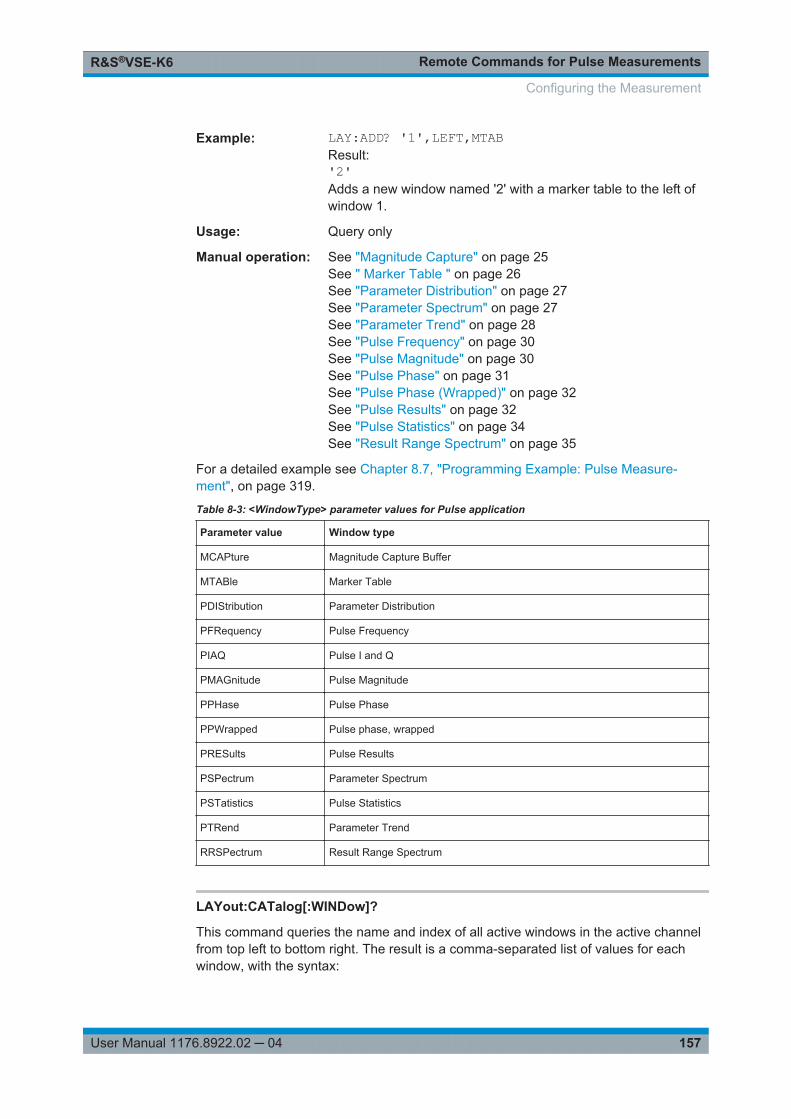
Remote Commands for Pulse MeasurementsR&S®VSE-K6
157User Manual 1176.8922.02 ─ 04
Example: LAY:ADD? '1',LEFT,MTABResult:'2'Adds a new window named '2' with a marker table to the left ofwindow 1.
Usage: Query only
Manual operation: See "Magnitude Capture" on page 25See " Marker Table " on page 26See "Parameter Distribution" on page 27See "Parameter Spectrum" on page 27See "Parameter Trend" on page 28See "Pulse Frequency" on page 30See "Pulse Magnitude" on page 30See "Pulse Phase" on page 31See "Pulse Phase (Wrapped)" on page 32See "Pulse Results" on page 32See "Pulse Statistics" on page 34See "Result Range Spectrum" on page 35
For a detailed example see Chapter 8.7, "Programming Example: Pulse Measure-ment", on page 319.
Table 8-3: <WindowType> parameter values for Pulse application
Parameter value Window type
MCAPture Magnitude Capture Buffer
MTABle Marker Table
PDIStribution Parameter Distribution
PFRequency Pulse Frequency
PIAQ Pulse I and Q
PMAGnitude Pulse Magnitude
PPHase Pulse Phase
PPWrapped Pulse phase, wrapped
PRESults Pulse Results
PSPectrum Parameter Spectrum
PSTatistics Pulse Statistics
PTRend Parameter Trend
RRSPectrum Result Range Spectrum
LAYout:CATalog[:WINDow]?
This command queries the name and index of all active windows in the active channelfrom top left to bottom right. The result is a comma-separated list of values for eachwindow, with the syntax:
Configuring the Measurement

Remote Commands for Pulse MeasurementsR&S®VSE-K6
158User Manual 1176.8922.02 ─ 04
<WindowName_1>,<WindowIndex_1>..<WindowName_n>,<WindowIndex_n>
To query the name and index of all windows in all channels use the LAYout:GLOBal:CATalog[:WINDow]? command.
Return values: <WindowName> string
Name of the window.In the default state, the name of the window is its index.
<WindowIndex> numeric valueIndex of the window.
Example: LAY:CAT?Result:'2',2,'1',1Two windows are displayed, named '2' (at the top or left), and '1'(at the bottom or right).
Usage: Query only
LAYout:IDENtify[:WINDow]? <WindowName>
This command queries the index of a particular display window in the active channel.
Note: to query the name of a particular window, use the LAYout:WINDow<n>:IDENtify? query.
To query the index of a window in a different channel use the LAYout:GLOBal:IDENtify[:WINDow]? command.
Query parameters: <WindowName> String containing the name of a window.
Return values: <WindowIndex> Index number of the window.
Example: LAY:WIND:IDEN? '2'Queries the index of the result display named '2'.Response:2
Usage: Query only
LAYout:REMove[:WINDow] <WindowName>
This command removes a window from the display in the active channel.
To remove a window for a different channel use the LAYout:GLOBal:REMove[:WINDow] command.
Setting parameters: <WindowName> String containing the name of the window.
In the default state, the name of the window is its index.
Configuring the Measurement

Remote Commands for Pulse MeasurementsR&S®VSE-K6
159User Manual 1176.8922.02 ─ 04
Example: LAY:REM '2'Removes the result display in the window named '2'.
Usage: Event
LAYout:REPLace[:WINDow] <WindowName>,<WindowType>
This command replaces the window type (for example from "Diagram" to "Result Sum-mary") of an already existing window in the active channel while keeping its position,index and window name.
To add a new window, use the LAYout:ADD[:WINDow]? command.
Parameters:<WindowName> String containing the name of the existing window.
By default, the name of a window is the same as its index. Todetermine the name and index of all active windows in the activechannel, use the LAYout:CATalog[:WINDow]? query.
<WindowType> Type of result display you want to use in the existing window.See LAYout:ADD[:WINDow]? on page 156 for a list of availa-ble window types.Note that the window type must be valid for the active channel.To create a window for a different channel use the LAYout:GLOBal:REPLace[:WINDow] command.
Example: LAY:REPL:WIND '1',MTABReplaces the result display in window 1 with a marker table.
LAYout:WINDow<n>:ADD? <Direction>,<WindowType>
This command adds a measurement window to the display. Note that with this com-mand, the suffix <n> determines the existing window next to which the new window isadded, as opposed to LAYout:ADD[:WINDow]?, for which the existing window isdefined by a parameter.
To replace an existing window, use the LAYout:WINDow<n>:REPLace command.
This command is always used as a query so that you immediately obtain the name ofthe new window as a result.
Suffix: <n>
.Window
Parameters:<Direction> LEFT | RIGHt | ABOVe | BELow
<WindowType> Type of measurement window you want to add.See LAYout:ADD[:WINDow]? on page 156 for a list of availa-ble window types.Note that the window type must be valid for the active channel.To create a window for a different channel use the LAYout:GLOBal:ADD[:WINDow]? command.
Configuring the Measurement

Remote Commands for Pulse MeasurementsR&S®VSE-K6
160User Manual 1176.8922.02 ─ 04
Return values: <NewWindowName> When adding a new window, the command returns its name (by
default the same as its number) as a result.
Example: LAY:WIND1:ADD? LEFT,MTABResult:'2'Adds a new window named '2' with a marker table to the left ofwindow 1.
Usage: Query only
LAYout:WINDow<n>:IDENtify?
This command queries the name of a particular display window (indicated by the <n>suffix) in the active channel.
Note: to query the index of a particular window, use the LAYout:IDENtify[:WINDow]? command.
Suffix: <n>
.Window
Return values: <WindowName> String containing the name of a window.
In the default state, the name of the window is its index.
Example: LAY:WIND2:IDEN?Queries the name of the result display in window 2.Response:'2'
Usage: Query only
LAYout:WINDow<n>:REMove
This command removes the window specified by the suffix <n> from the display in theactive channel.
The result of this command is identical to the LAYout:REMove[:WINDow] command.
To remove a window in a different channel use the LAYout:GLOBal:REMove[:WINDow] command.
Suffix: <n>
.Window
Example: LAY:WIND2:REMRemoves the result display in window 2.
Usage: Event
Configuring the Measurement

Remote Commands for Pulse MeasurementsR&S®VSE-K6
161User Manual 1176.8922.02 ─ 04
LAYout:WINDow<n>:REPLace <WindowType>
This command changes the window type of an existing window (specified by the suffix<n>) in the active channel.
The result of this command is identical to the LAYout:REPLace[:WINDow] com-mand.
To add a new window, use the LAYout:WINDow<n>:ADD? command.
Suffix: <n>
.Window
Setting parameters: <WindowType> Type of measurement window you want to replace another one
with.See LAYout:ADD[:WINDow]? on page 156 for a list of availa-ble window types.Note that the window type must be valid for the active channel.To create a window for a different channel use the LAYout:GLOBal:REPLace[:WINDow] command.
Example: LAY:WIND2:REPL MTABReplaces the result display in window 2 with a marker table.
8.4.9.3 General Window Commands
The following commands are required to work with windows, independently of theapplication.
Note that the suffix <n> always refers to the window in the currently selected measure-ment channel.
DISPlay:FORMat........................................................................................................... 161DISPlay[:WINDow<n>]:SELect........................................................................................ 161
DISPlay:FORMat <Format>
This command determines which tab is displayed.
Parameters:<Format> SPLit
Displays the MultiView tab with an overview of all active chan-nelsSINGleDisplays the measurement channel that was previously focused.*RST: SING
Example: DISP:FORM SPL
DISPlay[:WINDow<n>]:SELect
This command sets the focus on the selected result display window.
Configuring the Measurement
Remote Commands for Pulse MeasurementsR&S®VSE-K6
162User Manual 1176.8922.02 ─ 04
This window is then the active window.
Suffix: <n>
.Window
Example: //Put the focus on window 1DISP:WIND1:SEL
Usage: Setting only
8.4.10 Configuring the Results
Some evaluation methods require or allow for additional settings to configure the resultdisplay.
● Selecting the Pulse............................................................................................... 162● Defining the Result Range.................................................................................... 162● Configuring a Parameter Distribution....................................................................164● Configuring a Parameter Spectrum.......................................................................171● Configuring a Parameter Trend.............................................................................178● Configuring a Result Range Spectrum..................................................................207● Configuring the Statistics and Parameter Tables..................................................208● Configuring Limit Checks...................................................................................... 227● Configuring the Y-Axis Scaling and Units............................................................. 231
8.4.10.1 Selecting the Pulse
The pulse traces (frequency, magnitude and pulse vs. time) always display the tracefor one specific pulse, namely the currently selected pulse. To select a pulse, use thefollowing command:
SENSe:TRACe:MEASurement:DEFine:PULSe:SELected.................................................. 162
SENSe:TRACe:MEASurement:DEFine:PULSe:SELected <PulseNumber>
Selects a particular pulse for which the traces, parameters and results are displayed,or queries the number of the selected pulse. The number of the current or all detectedpulses can be queried using [SENSe:]PULSe:NUMBer? on page 256 or [SENSe:]PULSe:ID? on page 256.
Note that this command causes an error if no measurement results are available.
Parameters:<PulseNumber> Range: 0 to number of detected pulses
*RST: 0
8.4.10.2 Defining the Result Range
The result range determines which data is displayed on the screen (see also "Mea-surement range vs result range" on page 11). This range applies to the pulse magni-tude, frequency and phase vs time displays.
Configuring the Measurement

Remote Commands for Pulse MeasurementsR&S®VSE-K6
163User Manual 1176.8922.02 ─ 04
SENSe:TRACe:MEASurement:DEFine:RRANge:ALIGnment............................................. 163SENSe:TRACe:MEASurement:DEFine:RRANge:AUTO.....................................................163SENSe:TRACe:MEASurement:DEFine:RRANge:LENGth.................................................. 163SENSe:TRACe:MEASurement:DEFine:RRANge:OFFSet...................................................164SENSe:TRACe:MEASurement:DEFine:RRANge:REFerence............................................. 164
SENSe:TRACe:MEASurement:DEFine:RRANge:ALIGnment <Alignment>
Specifies the alignment with respect to the reference point used to define the resultrange.
Parameters:<Alignment> LEFT | CENTer | RIGHt
LEFTThe result range starts at the pulse center or selected edge.CENTerThe result range is centered around the pulse center or selectededge.RIGHtThe result range ends at the pulse center or selected edge.*RST: CENTer
Manual operation: See "Alignment" on page 80
SENSe:TRACe:MEASurement:DEFine:RRANge:AUTO <State>
If enabled, the result range length is determined automatically according to the width ofthe selected pulse (see SENSe:TRACe:MEASurement:DEFine:PULSe:SELectedon page 162).
Parameters:<State> OFF
Switch the function offONSwitch the function onONCEExecute the function once and then switch it off*RST: ON
Manual operation: See "Auto Scale Continuous (All)" on page 77See "Auto Scale Once (All)" on page 77See "Automatic Range Scaling" on page 79
SENSe:TRACe:MEASurement:DEFine:RRANge:LENGth <Length>
The length of the pulse result range (in seconds).
Parameters:<Length> *RST: 30 us
Default unit: S
Configuring the Measurement

Remote Commands for Pulse MeasurementsR&S®VSE-K6
164User Manual 1176.8922.02 ─ 04
Manual operation: See "Length" on page 80
SENSe:TRACe:MEASurement:DEFine:RRANge:OFFSet <Offset>
The offset (in seconds) from the reference point at which the pulse result range isaligned.
Parameters:<Offset> *RST: 0
Default unit: S
Manual operation: See "Offset" on page 80
SENSe:TRACe:MEASurement:DEFine:RRANge:REFerence <Reference>
Specifies the reference point used to define the result range.
Parameters:<Reference> RISE | CENTer | FALL
RISEThe result range is defined in reference to the rising edge.CENTerThe result range is defined in reference to the center of thepulse top.FALLThe result range is defined in reference to the falling edge.*RST: CENTer
Manual operation: See "Result Range Reference Point" on page 80
8.4.10.3 Configuring a Parameter Distribution
The parameter distribution evaluations allow you to visualize the number of occurren-ces for a specific parameter value within the current capture buffer. For each parame-ter distribution window you can configure which measured parameter is to be dis-played.
CALCulate<n>:DISTribution:EMODel...............................................................................164CALCulate<n>:DISTribution:FREQuency..........................................................................166CALCulate<n>:DISTribution:LLINes[:STATe].................................................................... 167CALCulate<n>:DISTribution:NBINs..................................................................................167CALCulate<n>:DISTribution:PHASe.................................................................................167CALCulate<n>:DISTribution:POWer.................................................................................168CALCulate<n>:DISTribution:TIMing................................................................................. 170
CALCulate<n>:DISTribution:EMODel <XAxis>, <YAxis>
Configures the Parameter Distribution result display.
Configuring the Measurement

Remote Commands for Pulse MeasurementsR&S®VSE-K6
165User Manual 1176.8922.02 ─ 04
Suffix: <n>
.1..nWindow
Setting parameters: <XAxis> RBPTime | RLPTime | RMPTime | RHPTime | RTPTime |
RLPLevel | RMPLevel | RHPLevel | RTPLevel | FBPTime |FLPTime | FMPTime | FHPTime | FTPTime | FLPLevel |FMPLevel | FHPLevel | FTPLevelRBPTimeRise Base Point TimeRLPTimeRise Low Point TimeRMPTimeRise Mid Point TimeRHPTimeRise High Point TimeRTPTimeRise Top Point TimeRLPLevelRise Low Point LevelRMPLevelRise Mid Point LevelRHPLevelRise High Point LevelRTPLevelRise Top Point LevelFBPTimeFall Base Point TimeFLPTimeFall Low Point TimeFMPTimeFall Mid Point TimeFHPTimeFall High Point TimeFTPTimeFall Top Point TimeFLPLevelFall Low Point LevelFMPLevelFall Mid Point LevelFHPLevelFall High Point LevelFTPLevelFall Top Point Level
Configuring the Measurement

Remote Commands for Pulse MeasurementsR&S®VSE-K6
166User Manual 1176.8922.02 ─ 04
<YAxis> COUNt | OCCurrenceParameter to be displayed on the y-axis.COUNtNumber of pulses in which the parameter value occurred.OCCurancePercentage of all measured pulses in which the parameter valueoccurred.*RST: COUNt
Usage: Setting only
CALCulate<n>:DISTribution:FREQuency <XAxis>, <YAxis>
Configures the Parameter Distribution result display.
Suffix: <n>
.1..nWindow
Setting parameters: <XAxis> POINt | PPFRequency | RERRor | PERRor | DEViation | CRATe
Pulse parameter to be displayed on the x-axis. For a descriptionof the available parameters see Chapter 3.1.3, "FrequencyParameters", on page 18.POINtFrequency at measurement pointPPFRequencyPulse-Pulse Frequency DifferenceRERRorFrequency Error (RMS)PERRorFrequency Error (Peak)DEViationFrequency DeviationCRATeChirp Rate*RST: POINt
<YAxis> COUNt | OCCurrenceParameter to be displayed on the y-axis.COUNtNumber of pulses in which the parameter value occurred.OCCurencePercentage of all measured pulses in which the parameter valueoccurred.*RST: COUNt
Usage: Setting only
Configuring the Measurement

Remote Commands for Pulse MeasurementsR&S®VSE-K6
167User Manual 1176.8922.02 ─ 04
Manual operation: See "X-Axis" on page 83
CALCulate<n>:DISTribution:LLINes[:STATe] <State>
Hides or shows the limit lines in the selected Parameter Trend or Parameter Distribu-tion result display.
Note that this function only has an effect on the visibility of the lines in the graphicaldisplays, it does not affect the limit check in general or the display of the limit checkresults in the table displays.
Suffix: <n>
.Window
Parameters:<State> ON | OFF | 1 | 0
*RST: 1
Example: CALC:DIST:LLIN ONManual operation: See "Display Limit Lines" on page 84
CALCulate<n>:DISTribution:NBINs <# bins>
This command sets the number of bins used to calculate the historgram
Suffix: <n>
.1..nWindow
Parameters:<# bins> Range: 1 to 1000
*RST: 100
Manual operation: See "Histogram Bins" on page 84
CALCulate<n>:DISTribution:PHASe <XAxis>, <YAxis>
Configures the Parameter Distribution result display.
Suffix: <n>
.1..nWindow
Configuring the Measurement

Remote Commands for Pulse MeasurementsR&S®VSE-K6
168User Manual 1176.8922.02 ─ 04
Setting parameters: <XAxis> POINt | PPPHase | RERRor | PERRor | DEViation
Pulse parameter to be displayed on the x-axis. For a descriptionof the available parameters see Chapter 3.1.4, "Phase Parame-ters", on page 20.POINtPulse phase at measurement pointPPPHasePulse-Pulse Phase DifferenceRERRorPhase Error (RMS)PERRorPhase Error (Peak)DEViationPhase Deviation*RST: POINt
<YAxis> COUNt | OCCurrenceParameter to be displayed on the y-axis.COUNtNumber of pulses in which the parameter value occurred.OCCurancePercentage of all measured pulses in which the parameter valueoccurred.*RST: COUNt
Usage: Setting only
CALCulate<n>:DISTribution:POWer <XAxis>, <YAxis>
Configures the Parameter Distribution result display.
Suffix: <n>
.1..nWindow
Configuring the Measurement

Remote Commands for Pulse MeasurementsR&S®VSE-K6
169User Manual 1176.8922.02 ─ 04
Setting parameters: <XAxis> TOP | BASE | AMPLitude | ON | AVG | MIN | MAX | PON |
PAVG | PMIN | ADPercent | ADDB | RPERcent | RDB |OPERcent | ODB | POINt | PPRatioPulse parameter to be displayed on the x-axis. For a descriptionof the available parameters see Chapter 3.1.4, "Phase Parame-ters", on page 20.TOPTop PowerBASEBase PowerAMPLitudePulse AmplitudeONAverage ON PowerAVGAverage Tx PowerMINMinimum PowerMAXPeak PowerPONPeak-to-Avg ON Power RatioPAVGPeak-to-Average Tx Power RatioPMINPeak-to-Min Power RatioADPercentDroop in %ADDBDroop in dBRPERcentRipple in %RDBRipple in dBOPERcentOvershoot in %ODBOvershoot in dBPOINtPulse power measured at measurement pointPPRatioPulse-to-Pulse Power Difference*RST: TOP
Configuring the Measurement
Remote Commands for Pulse MeasurementsR&S®VSE-K6
170User Manual 1176.8922.02 ─ 04
<YAxis> COUNt | OCCurrenceParameter to be displayed on the y-axis.COUNtNumber of pulses in which the parameter value occurred.OCCurancePercentage of all measured pulses in which the parameter valueoccurred.*RST: COUNt
Usage: Setting only
CALCulate<n>:DISTribution:TIMing <XAxis>, <YAxis>
Configures the Parameter Distribution result display.
Suffix: <n>
.1..nWindow
Setting parameters: <XAxis> TSTamp | SETTling | RISE | FALL | PWIDth | OFF | DRATio |
DCYCle | PRI | PRFPulse parameter to be displayed on the x-axis. For a descriptionof the available parameters see Chapter 3.1.1, "Timing Parame-ters", on page 12.TSTampTimestampSETTlingSettling TimeRISERise TimeFALLFall TimePWIDthPulse Width (ON Time)OFFOff TimeDRATioDuty RatioDCYCleDuty Cycle (%)PRIPulse Repetition IntervalPRFPulse Repetition Frequency (Hz)*RST: RISE
Configuring the Measurement

Remote Commands for Pulse MeasurementsR&S®VSE-K6
171User Manual 1176.8922.02 ─ 04
<YAxis> COUNt | OCCurrenceParameter to be displayed on the y-axis.COUNtNumber of pulses in which the parameter value occurred.OCCurancePercentage of all measured pulses in which the parameter valueoccurred.*RST: COUNt
Usage: Setting only
8.4.10.4 Configuring a Parameter Spectrum
The parameter spectrum evaluations allow you to visualize the spectrum of results fora specific parameter for all measured pulses within the current capture buffer. For eachparameter spectrum window you can configure which measured parameter is to be dis-played.
CALCulate<n>:PSPectrum:AUTO....................................................................................171CALCulate<n>:PSPectrum:BLOCksize.............................................................................172CALCulate<n>:PSPectrum:EMODel.................................................................................172CALCulate<n>:PSPectrum:FREQuency........................................................................... 173CALCulate<n>:PSPectrum:GTHReshold.......................................................................... 174CALCulate<n>:PSPectrum:MAXFrequency...................................................................... 174CALCulate<n>:PSPectrum:PHASe.................................................................................. 175CALCulate<n>:PSPectrum:POWer.................................................................................. 175CALCulate<n>:PSPectrum:RBW?................................................................................... 177CALCulate<n>:PSPectrum:STHReshold.......................................................................... 177CALCulate<n>:PSPectrum:TIMing...................................................................................177CALCulate<n>:PSPectrum:WINDow................................................................................ 178
CALCulate<n>:PSPectrum:AUTO <State>
Enables or disables automatic configuration for Parameter Spectrum displays. Ifenabled, the commands for individual settings are not available.
Suffix: <n>
.1..nWindow
Parameters:<State> ON | OFF | 1 | 0
*RST: 1
Manual operation: See "Full Auto" on page 86
Configuring the Measurement

Remote Commands for Pulse MeasurementsR&S®VSE-K6
172User Manual 1176.8922.02 ─ 04
CALCulate<n>:PSPectrum:BLOCksize <BlockSize>
Defines the size of blocks used in spectrum calculation. The block size also determinesthe resulting RBW of the spectrum (see CALCulate<n>:PSPectrum:RBW?on page 177).
Suffix: <n>
.1..nWindow
Parameters:<BlockSize> Range: 8 to 100k
*RST: 1024
Manual operation: See "Block Size" on page 86
CALCulate<n>:PSPectrum:EMODel <Param>
Suffix: <n>
.1..nWindow
Configuring the Measurement

Remote Commands for Pulse MeasurementsR&S®VSE-K6
173User Manual 1176.8922.02 ─ 04
Setting parameters: <Param> RBPTime | RLPTime | RMPTime | RHPTime | RTPTime |
RLPLevel | RMPLevel | RHPLevel | RTPLevel | FBPTime |FLPTime | FMPTime | FHPTime | FTPTime | FLPLevel |FMPLevel | FHPLevel | FTPLevelRBPTimeRise Base Point TimeRLPTimeRise Low Point TimeRMPTimeRise Mid Point TimeRHPTimeRise High Point TimeRTPTimeRise Top Point TimeRLPLevelRise Low Point LevelRMPLevelRise Mid Point LevelRHPLevelRise High Point LevelRTPLevelRise Top Point LevelFBPTimeFall Base Point TimeFLPTimeFall Low Point TimeFMPTimeFall Mid Point TimeFHPTimeFall High Point TimeFTPTimeFall Top Point TimeFLPLevelFall Low Point LevelFMPLevelFall Mid Point LevelFHPLevelFall High Point LevelFTPLevelFall Top Point Level
CALCulate<n>:PSPectrum:FREQuency <Param>
Configures the Parameter Spectrum result display.
Configuring the Measurement

Remote Commands for Pulse MeasurementsR&S®VSE-K6
174User Manual 1176.8922.02 ─ 04
Suffix: <n>
.1..nWindow
Setting parameters: <Param> POINt | PPFRequency | RERRor | PERRor | DEViation | CRATe
Pulse parameter to be displayed on the x-axis. For a descriptionof the available parameters see Chapter 3.1.3, "FrequencyParameters", on page 18.POINtFrequency at measurement pointPPFRequencyPulse-Pulse Frequency DifferenceRERRorFrequency Error (RMS)PERRorFrequency Error (Peak)DEViationFrequency DeviationCRATeChirp Rate*RST: POINt
Manual operation: See "Parameter" on page 86
CALCulate<n>:PSPectrum:GTHReshold <GapThreshold>
Defines the minimum time that must pass before a gap is detected as such.
Suffix: <n>
.1..nWindow
Parameters:<GapThreshold> Range: minimum spacing between pulses to meas time
Default unit: S
Manual operation: See "Gap Threshold" on page 86
CALCulate<n>:PSPectrum:MAXFrequency <MaxFrequncy>
Defines the maximum frequency span for which the Spectrum is calculated. Internally,the span is limited by the number of possible interpolation samples (100 000).
Suffix: <n>
.1..nWindow
Configuring the Measurement

Remote Commands for Pulse MeasurementsR&S®VSE-K6
175User Manual 1176.8922.02 ─ 04
Parameters:<MaxFrequncy> Range: >0 to 1/10 of sample rate
Default unit: HZ
Manual operation: See "Maximum Frequency" on page 86
CALCulate<n>:PSPectrum:PHASe <Param>
Configures the Parameter Spectrum result display.
Suffix: <n>
.1..nWindow
Setting parameters: <Param> POINt | PPPHase | RERRor | PERRor | DEViation
Pulse parameter to be displayed on the x-axis. For a descriptionof the available parameters see Chapter 3.1.4, "Phase Parame-ters", on page 20.POINtPulse phase at measurement pointPPPHasePulse-Pulse Phase DifferenceRERRorPhase Error (RMS)PERRorPhase Error (Peak)DEViationPhase Deviation*RST: POINt
CALCulate<n>:PSPectrum:POWer <Param>
Configures the Parameter Spectrum result display.
Suffix: <n>
.1..nWindow
Configuring the Measurement

Remote Commands for Pulse MeasurementsR&S®VSE-K6
176User Manual 1176.8922.02 ─ 04
Setting parameters: <Param> TOP | BASE | AMPLitude | ON | AVG | MIN | MAX | PON |
PAVG | PMIN | ADPercent | ADDB | RPERcent | RDB |OPERcent | ODB | POINt | PPRatioPulse parameter to be displayed on the x-axis. For a descriptionof the available parameters see Chapter 3.1.4, "Phase Parame-ters", on page 20.TOPTop PowerBASEBase PowerAMPLitudePulse AmplitudeONAverage ON PowerAVGAverage Tx PowerMINMinimum PowerMAXPeak PowerPONPeak-to-Avg ON Power RatioPAVGPeak-to-Average Tx Power RatioPMINPeak-to-Min Power RatioADPercentDroop in %ADDBDroop in dBRPERcentRipple in %RDBRipple in dBOPERcentOvershoot in %ODBOvershoot in dBPOINtPulse power measured at measurement pointPPRatioPulse-to-Pulse Power Difference*RST: TOP
Configuring the Measurement

Remote Commands for Pulse MeasurementsR&S®VSE-K6
177User Manual 1176.8922.02 ─ 04
CALCulate<n>:PSPectrum:RBW?
Queries the resulting resolution bandwidth for the spectrum. Depends on the block size(see CALCulate<n>:PSPectrum:BLOCksize on page 172).
Suffix: <n>
.1..nWindow
Return values: <RBW> Default unit: Hz
Usage: Query only
CALCulate<n>:PSPectrum:STHReshold <Threshold>
Defines the minimum section size. Sections that are smaller than the threshold areignored and considered to be part of the detected gap.
Suffix: <n>
.1..nWindow
Parameters:<Threshold> Minimum section size as a percentage of the block size (see
CALCulate<n>:PSPectrum:BLOCksize on page 172)
Range: 0 to 100*RST: 50
Manual operation: See "Section Threshold" on page 86
CALCulate<n>:PSPectrum:TIMing <Param>
Configures the Parameter Spectrum result display.
Suffix: <n>
.1..nWindow
Configuring the Measurement

Remote Commands for Pulse MeasurementsR&S®VSE-K6
178User Manual 1176.8922.02 ─ 04
Setting parameters: <Param> TSTamp | SETTling | RISE | FALL | PWIDth | OFF | DRATio |
DCYCle | PRI | PRFPulse parameter to be displayed on the x-axis. For a descriptionof the available parameters see Chapter 3.1.1, "Timing Parame-ters", on page 12.TSTampTimestampSETTlingSettling TimeRISERise TimeFALLFall TimePWIDthPulse Width (ON Time)OFFOff TimeDRATioDuty RatioDCYCleDuty Cycle (%)PRIPulse Repetition IntervalPRFPulse Repetition Frequency (Hz)*RST: RISE
CALCulate<n>:PSPectrum:WINDow <WindowType>
Defines the used FFT window type
Suffix: <n>
.1..nWindow
Setting parameters: <WindowType> RECTangle | BARTlett | HAMMing | HANNing | BLACkman
*RST: BLACkman
Manual operation: See "Window Type" on page 86
8.4.10.5 Configuring a Parameter Trend
The parameter trend evaluations allow you to visualize changes in a specific parameterfor all measured pulses within the current capture buffer. For each parameter trendwindow you can configure which measured parameter is to be displayed.
Configuring the Measurement

Remote Commands for Pulse MeasurementsR&S®VSE-K6
179User Manual 1176.8922.02 ─ 04
CALCulate<n>:TRENd:DSTYle....................................................................................... 179CALCulate<n>:TRENd:EMODel...................................................................................... 179CALCulate<n>:TRENd:EMODel:X................................................................................... 181CALCulate<n>:TRENd:EMODel:Y................................................................................... 183CALCulate<n>:TRENd:FREQuency.................................................................................185CALCulate<n>:TRENd:FREQuency:X..............................................................................186CALCulate<n>:TRENd:FREQuency:Y..............................................................................187CALCulate<n>:TRENd:LLINes[:STATe]............................................................................188CALCulate<n>:TRENd:PHASe........................................................................................189CALCulate<n>:TRENd:PHASe:X.....................................................................................190CALCulate<n>:TRENd:PHASe:Y.....................................................................................191CALCulate<n>:TRENd:POWer........................................................................................192CALCulate<n>:TRENd:POWer:X.....................................................................................194CALCulate<n>:TRENd:POWer:Y.....................................................................................196CALCulate<n>:TRENd:POWer:X.....................................................................................198CALCulate<n>:TRENd:POWer:Y.....................................................................................200CALCulate<n>:TRENd:TIMing.........................................................................................202CALCulate<n>:TRENd:TIMing:X......................................................................................203CALCulate<n>:TRENd:TIMing:Y......................................................................................204CALCulate<n>:TRENd:TIMing:X......................................................................................205CALCulate<n>:TRENd:TIMing:Y......................................................................................206
CALCulate<n>:TRENd:DSTYle <Type>
Suffix: <n>
.1..nWindow
Parameters:<Type> AUTO | DOTS | LINes | DLINes
CALCulate<n>:TRENd:EMODel <YAxis>, <XAxis>
Configures the Parameter Trend result display for envelope model trends. This com-mand defines both x-axis and y-axis parameters in one step. It is equivalent to the twosubsequent commands:
CALCulate<n>:TRENd:EMODel:X TSTamp | PNUMber (see CALCulate<n>:TRENd:EMODel:X on page 181)
CALCulate<n>:TRENd:EMODel:Y <YAxis> (see CALCulate<n>:TRENd:EMODel:Y on page 183)
Suffix: <n>
.1..nWindow
Configuring the Measurement

Remote Commands for Pulse MeasurementsR&S®VSE-K6
180User Manual 1176.8922.02 ─ 04
Setting parameters: <YAxis> RBPTime | RLPTime | RMPTime | RHPTime | RTPTime |
RLPLevel | RMPLevel | RHPLevel | RTPLevel | FBPTime |FLPTime | FMPTime | FHPTime | FTPTime | FLPLevel |FMPLevel | FHPLevel | FTPLevelRBPTimeRise Base Point TimeRLPTimeRise Low Point TimeRMPTimeRise Mid Point TimeRHPTimeRise High Point TimeRTPTimeRise Top Point TimeRLPLevelRise Low Point LevelRMPLevelRise Mid Point LevelRHPLevelRise High Point LevelRTPLevelRise Top Point LevelFBPTimeFall Base Point TimeFLPTimeFall Low Point TimeFMPTimeFall Mid Point TimeFHPTimeFall High Point TimeFTPTimeFall Top Point TimeFLPLevelFall Low Point LevelFMPLevelFall Mid Point LevelFHPLevelFall High Point LevelFTPLevelFall Top Point Level
Configuring the Measurement

Remote Commands for Pulse MeasurementsR&S®VSE-K6
181User Manual 1176.8922.02 ─ 04
<XAxis> PNUMber | TSTamp | SETTling | RISE | FALL | PWIDth | OFF |DRATio | DCYCle | PRI | PRFPulse parameter to be displayed on the x-axis. For a descriptionof the available parameters see Chapter 3.1.1, "Timing Parame-ters", on page 12.TSTampTimestampPNUMberThe pulse numbers are represented on the x-axis (availablenumbers can be queried using [SENSe:]PULSe:NUMBer?on page 256). Intervals without pulses are not displayed.SETTlingSettling TimeRISERise TimeFALLFall TimePWIDthPulse Width (ON Time)OFFOff TimeDRATioDuty RatioDCYCleDuty Cycle (%)PRIPulse Repetition IntervalPRFPulse Repetition Frequency (Hz)*RST: PNUMber
Usage: Setting only
CALCulate<n>:TRENd:EMODel:X <XAxis>
Configures the x-axis of the Parameter Trend result display.
The y-axis is configured using the CALCulate<n>:TRENd:<GroupName>:Y com-mands.
Suffix: <n>
.1..nWindow
Configuring the Measurement

Remote Commands for Pulse MeasurementsR&S®VSE-K6
182User Manual 1176.8922.02 ─ 04
Setting parameters: <XAxis> RBPTime | RLPTime | RMPTime | RHPTime | RTPTime |
RLPLevel | RMPLevel | RHPLevel | RTPLevel | FBPTime |FLPTime | FMPTime | FHPTime | FTPTime | FLPLevel |FMPLevel | FHPLevel | FTPLevelRBPTimeRise Base Point TimeRLPTimeRise Low Point TimeRMPTimeRise Mid Point TimeRHPTimeRise High Point TimeRTPTimeRise Top Point TimeRLPLevelRise Low Point LevelRMPLevelRise Mid Point LevelRHPLevelRise High Point LevelRTPLevelRise Top Point LevelFBPTimeFall Base Point TimeFLPTimeFall Low Point TimeFMPTimeFall Mid Point TimeFHPTimeFall High Point TimeFTPTimeFall Top Point TimeFLPLevelFall Low Point LevelFMPLevelFall Mid Point LevelFHPLevelFall High Point LevelFTPLevelFall Top Point Level
Usage: Setting only
Configuring the Measurement

Remote Commands for Pulse MeasurementsR&S®VSE-K6
183User Manual 1176.8922.02 ─ 04
CALCulate<n>:TRENd:EMODel:Y <YAxis>
Configures the y-axis of the Parameter Trend result display.
The x-axis is configured using the CALCulate<n>:TRENd:<GroupName>:X com-mands.
Suffix: <n>
.1..nWindow
Configuring the Measurement

Remote Commands for Pulse MeasurementsR&S®VSE-K6
184User Manual 1176.8922.02 ─ 04
Setting parameters: <YAxis> RBPTime | RLPTime | RMPTime | RHPTime | RTPTime |
RLPLevel | RMPLevel | RHPLevel | RTPLevel | FBPTime |FLPTime | FMPTime | FHPTime | FTPTime | FLPLevel |FMPLevel | FHPLevel | FTPLevelRBPTimeRise Base Point TimeRLPTimeRise Low Point TimeRMPTimeRise Mid Point TimeRHPTimeRise High Point TimeRTPTimeRise Top Point TimeRLPLevelRise Low Point LevelRMPLevelRise Mid Point LevelRHPLevelRise High Point LevelRTPLevelRise Top Point LevelFBPTimeFall Base Point TimeFLPTimeFall Low Point TimeFMPTimeFall Mid Point TimeFHPTimeFall High Point TimeFTPTimeFall Top Point TimeFLPLevelFall Low Point LevelFMPLevelFall Mid Point LevelFHPLevelFall High Point LevelFTPLevelFall Top Point Level
Usage: Setting only
Configuring the Measurement

Remote Commands for Pulse MeasurementsR&S®VSE-K6
185User Manual 1176.8922.02 ─ 04
CALCulate<n>:TRENd:FREQuency <YAxis>, <XAxis>
Configures the Parameter Trend result display for time trends. This command definesboth x-axis and y-axis parameters in one step. It is equivalent to the two subsequentcommands:
CALCulate<n>:TRENd:TIMing:X TSTamp | PNUMber (see CALCulate<n>:TRENd:TIMing:X on page 205)
CALCulate<n>:TRENd:FREQuency:Y <YAxis> (see CALCulate<n>:TRENd:FREQuency:Y on page 187)
Suffix: <n>
.1..nWindow
Setting parameters: <YAxis> POINt | PPFRequency | RERRor | PERRor | DEViation | CRATe
Pulse parameter to be displayed on the y-axis. For a descriptionof the available parameters see Chapter 3.1.3, "FrequencyParameters", on page 18.POINtFrequency at measurement pointPPFRequencyPulse-Pulse Frequency DifferenceRERRorFrequency Error (RMS)PERRorFrequency Error (Peak)DEViationFrequency DeviationCRATeChirp Rate*RST: POINt
Configuring the Measurement

Remote Commands for Pulse MeasurementsR&S®VSE-K6
186User Manual 1176.8922.02 ─ 04
<XAxis> PNUMber | TSTamp | SETTling | RISE | FALL | PWIDth | OFF |DRATio | DCYCle | PRI | PRFPulse parameter to be displayed on the x-axis. For a descriptionof the available parameters see Chapter 3.1.1, "Timing Parame-ters", on page 12.TSTampTimestampPNUMberThe pulse numbers are represented on the x-axis (availablenumbers can be queried using [SENSe:]PULSe:NUMBer?on page 256). Intervals without pulses are not displayed.SETTlingSettling TimeRISERise TimeFALLFall TimePWIDthPulse Width (ON Time)OFFOff TimeDRATioDuty RatioDCYCleDuty Cycle (%)PRIPulse Repetition IntervalPRFPulse Repetition Frequency (Hz)*RST: PNUMber
Usage: Setting only
Manual operation: See "Y-Axis" on page 88See "X-Axis" on page 88
CALCulate<n>:TRENd:FREQuency:X <XAxis>
Configures the x-axis of the Parameter Trend result display.
The y-axis is configured using the CALCulate<n>:TRENd:<GroupName>:Y com-mands.
Suffix: <n>
.1..nWindow
Configuring the Measurement

Remote Commands for Pulse MeasurementsR&S®VSE-K6
187User Manual 1176.8922.02 ─ 04
Setting parameters: <XAxis> POINt | PPFRequency | RERRor | PERRor | DEViation | CRATe
Pulse parameter to be displayed on the x-axis. For a descriptionof the available parameters see Chapter 3.1.3, "FrequencyParameters", on page 18.POINtFrequency at measurement pointPPFRequencyPulse-Pulse Frequency DifferenceRERRorFrequency Error (RMS)PERRorFrequency Error (Peak)DEViationFrequency DeviationCRATeChirp Rate*RST: POINt
Example: CALC2:TREN:FREQ:X PERRUsage: Setting only
Manual operation: See "X-Axis" on page 88
CALCulate<n>:TRENd:FREQuency:Y <YAxis>
Configures the y-axis of the Parameter Trend result display.
The x-axis is configured using the CALCulate<n>:TRENd:<GroupName>:X com-mands.
Suffix: <n>
.1..nWindow
Configuring the Measurement

Remote Commands for Pulse MeasurementsR&S®VSE-K6
188User Manual 1176.8922.02 ─ 04
Setting parameters: <YAxis> POINt | PPFRequency | RERRor | PERRor | DEViation | CRATe
Pulse parameter to be displayed on the y-axis. For a descriptionof the available parameters see Chapter 3.1.3, "FrequencyParameters", on page 18.POINtFrequency at measurement pointPPFRequencyPulse-Pulse Frequency DifferenceRERRorFrequency Error (RMS)PERRorFrequency Error (Peak)DEViationFrequency DeviationCRATeChirp Rate*RST: POINt
Usage: Setting only
Manual operation: See "Y-Axis" on page 88
CALCulate<n>:TRENd:LLINes[:STATe] <State>
Hides or shows the limit lines in the selected Parameter Trend or Parameter Distribu-tion result display.
Note that this function only has an effect on the visibility of the lines in the graphicaldisplays, it does not affect the limit check in general or the display of the limit checkresults in the table displays.
Suffix: <n>
.Window
Parameters:<State> ON | OFF | 0 | 1
OFF | 0Switches the function offON | 1Switches the function on*RST: 1
Manual operation: See "Display Limit Lines" on page 84
Configuring the Measurement

Remote Commands for Pulse MeasurementsR&S®VSE-K6
189User Manual 1176.8922.02 ─ 04
CALCulate<n>:TRENd:PHASe <YAxis>, <XAxis>
Configures the Parameter Trend result display for time trends. This command definesboth x-axis and y-axis parameters in one step. It is equivalent to the two subsequentcommands:
CALCulate<n>:TRENd:TIMing:X TSTamp | PNUMber (see CALCulate<n>:TRENd:TIMing:X on page 205)
CALCulate<n>:TRENd:PHASe:Y <YAxis> (see CALCulate<n>:TRENd:PHASe:Yon page 191)
Suffix: <n>
.1..nWindow
Setting parameters: <YAxis> POINt | PPPHase | RERRor | PERRor | DEViation
Pulse parameter to be displayed on the y-axis. For a descriptionof the available parameters see Chapter 3.1.4, "Phase Parame-ters", on page 20.POINtPulse phase at measurement pointPPPHasePulse-Pulse Phase DifferenceRERRorPhase Error (RMS)PERRorPhase Error (Peak)DEViationPhase Deviation*RST: POINt
Configuring the Measurement

Remote Commands for Pulse MeasurementsR&S®VSE-K6
190User Manual 1176.8922.02 ─ 04
<XAxis> PNUMber | TSTamp | SETTling | RISE | FALL | PWIDth | OFF |DRATio | DCYCle | PRI | PRFPulse parameter to be displayed on the x-axis. For a descriptionof the available parameters see Chapter 3.1.1, "Timing Parame-ters", on page 12.TSTampTimestampPNUMberThe pulse numbers are represented on the x-axis (availablenumbers can be queried using [SENSe:]PULSe:NUMBer?on page 256). Intervals without pulses are not displayed.SETTlingSettling TimeRISERise TimeFALLFall TimePWIDthPulse Width (ON Time)OFFOff TimeDRATioDuty RatioDCYCleDuty Cycle (%)PRIPulse Repetition IntervalPRFPulse Repetition Frequency (Hz)*RST: PNUMber
Usage: Setting only
CALCulate<n>:TRENd:PHASe:X <XAxis>
Configures the x-axis of the Parameter Trend result display.
The y-axis is configured using the CALCulate<n>:TRENd:<GroupName>:Y com-mands.
Suffix: <n>
.1..nWindow
Configuring the Measurement

Remote Commands for Pulse MeasurementsR&S®VSE-K6
191User Manual 1176.8922.02 ─ 04
Setting parameters: <XAxis> POINt | PPPHase | RERRor | PERRor | DEViation
Pulse parameter to be displayed on the x-axis. For a descriptionof the available parameters see Chapter 3.1.4, "Phase Parame-ters", on page 20.POINtPulse phase at measurement pointPPPHasePulse-Pulse Phase DifferenceRERRorPhase Error (RMS)PERRorPhase Error (Peak)DEViationPhase Deviation*RST: POINt
Example: CALC2:TREN:PHAS:X PERRUsage: Setting only
CALCulate<n>:TRENd:PHASe:Y <YAxis>
Configures the y-axis of the Parameter Trend result display.
The x-axis is configured using the CALCulate<n>:TRENd:<GroupName>:X com-mands.
Suffix: <n>
.1..nWindow
Setting parameters: <YAxis> POINt | PPPHase | RERRor | PERRor | DEViation
Pulse parameter to be displayed on the y-axis. For a descriptionof the available parameters see Chapter 3.1.4, "Phase Parame-ters", on page 20.POINtPulse phase at measurement pointPPPHasePulse-Pulse Phase DifferenceRERRorPhase Error (RMS)PERRorPhase Error (Peak)DEViationPhase Deviation*RST: POINt
Configuring the Measurement

Remote Commands for Pulse MeasurementsR&S®VSE-K6
192User Manual 1176.8922.02 ─ 04
Usage: Setting only
CALCulate<n>:TRENd:POWer <YAxis>, <XAxis>
Configures the Parameter Trend result display for time trends. This command definesboth x-axis and y-axis parameters in one step. It is equivalent to the two subsequentcommands:
CALCulate<n>:TRENd:TIMing:X TSTamp | PNUMber (see CALCulate<n>:TRENd:TIMing:X on page 205)
CALCulate<n>:TRENd:POWer:Y <YAxis> (see CALCulate<n>:TRENd:POWer:Yon page 200)
Suffix: <n>
.1..nWindow
Configuring the Measurement

Remote Commands for Pulse MeasurementsR&S®VSE-K6
193User Manual 1176.8922.02 ─ 04
Setting parameters: <YAxis> TOP | BASE | AMPLitude | ON | AVG | MIN | MAX | PON |
PAVG | PMIN | ADPercent | ADDB | RPERcent | RDB |OPERcent | ODB | POINt | PPRatioPulse parameter to be displayed on the y-axis. For a descriptionof the available parameters see Chapter 3.1.2, "Power/Ampli-tude Parameters", on page 15.TOPTop PowerBASEBase PowerAMPLitudePulse AmplitudeONAverage ON PowerAVGAverage Tx PowerMINMinimum PowerMAXPeak PowerPONPeak-to-Avg ON Power RatioPAVGPeak-to-Average Tx Power RatioPMINPeak-to-Min Power RatioADPercentDroop in %ADDBDroop in dBRPERcentRipple in %RDBRipple in dBOPERcentOvershoot in %ODBOvershoot in dBPOINtPulse power measured at measurement pointPPRatioPulse-to-Pulse Power Difference*RST: TOP
Configuring the Measurement

Remote Commands for Pulse MeasurementsR&S®VSE-K6
194User Manual 1176.8922.02 ─ 04
<XAxis> PNUMber | TSTamp | SETTling | RISE | FALL | PWIDth | OFF |DRATio | DCYCle | PRI | PRFPulse parameter to be displayed on the x-axis. For a descriptionof the available parameters see Chapter 3.1.1, "Timing Parame-ters", on page 12.TSTampTimestampPNUMberThe pulse numbers are represented on the x-axis (availablenumbers can be queried using [SENSe:]PULSe:NUMBer?on page 256). Intervals without pulses are not displayed.SETTlingSettling TimeRISERise TimeFALLFall TimePWIDthPulse Width (ON Time)OFFOff TimeDRATioDuty RatioDCYCleDuty Cycle (%)PRIPulse Repetition IntervalPRFPulse Repetition Frequency (Hz)*RST: PNUMber
Usage: Setting only
CALCulate<n>:TRENd:POWer:X <XAxis>
Configures the x-axis of the Parameter Trend result display.
The y-axis is configured using the CALCulate<n>:TRENd:<GroupName>:Y com-mands.
Suffix: <n>
.1..nWindow
Configuring the Measurement

Remote Commands for Pulse MeasurementsR&S®VSE-K6
195User Manual 1176.8922.02 ─ 04
Setting parameters: <XAxis> TOP | BASE | AMPLitude | ON | AVG | MIN | MAX | PON |
PAVG | PMIN | ADPercent | ADDB | RPERcent | RDB |OPERcent | ODB | POINt | PPRatioPulse parameter to be displayed on the x-axis. For a descriptionof the available parameters see Chapter 3.1.2, "Power/Ampli-tude Parameters", on page 15.TOPTop PowerBASEBase PowerAMPLitudePulse AmplitudeONAverage ON PowerAVGAverage Tx PowerMINMinimum PowerMAXPeak PowerPONPeak-to-Avg ON Power RatioPAVGPeak-to-Average Tx Power RatioPMINPeak-to-Min Power RatioADPercentDroop in %ADDBDroop in dBRPERcentRipple in %RDBRipple in dBOPERcentOvershoot in %ODBOvershoot in dBPOINtPulse power measured at measurement pointPPRatioPulse-to-Pulse Power Difference*RST: TOP
Configuring the Measurement
Remote Commands for Pulse MeasurementsR&S®VSE-K6
196User Manual 1176.8922.02 ─ 04
Example: CALC2:TREN:POW:X ODBUsage: Setting only
CALCulate<n>:TRENd:POWer:Y <YAxis>
Configures the y-axis of the Parameter Trend result display.
The x-axis is configured using the CALCulate<n>:TRENd:<GroupName>:X com-mands.
Suffix: <n>
.1..nWindow
Configuring the Measurement
Remote Commands for Pulse MeasurementsR&S®VSE-K6
197User Manual 1176.8922.02 ─ 04
Setting parameters: <YAxis> TOP | BASE | AMPLitude | ON | AVG | MIN | MAX | PON |
PAVG | PMIN | ADPercent | ADDB | RPERcent | RDB |OPERcent | ODB | POINt | PPRatioPulse parameter to be displayed on the y-axis. For a descriptionof the available parameters see Chapter 3.1.2, "Power/Ampli-tude Parameters", on page 15.TOPTop PowerBASEBase PowerAMPLitudePulse AmplitudeONAverage ON PowerAVGAverage Tx PowerMINMinimum PowerMAXPeak PowerPONPeak-to-Avg ON Power RatioPAVGPeak-to-Average Tx Power RatioPMINPeak-to-Min Power RatioADPercentDroop in %ADDBDroop in dBRPERcentRipple in %RDBRipple in dBOPERcentOvershoot in %ODBOvershoot in dBPOINtPulse power measured at measurement pointPPRatioPulse-to-Pulse Power Difference*RST: TOP
Configuring the Measurement

Remote Commands for Pulse MeasurementsR&S®VSE-K6
198User Manual 1176.8922.02 ─ 04
Usage: Setting only
CALCulate<n>:TRENd:POWer:X <XAxis>
Configures the x-axis of the Parameter Trend result display.
The y-axis is configured using the CALCulate<n>:TRENd:<GroupName>:Y com-mands.
Suffix: <n>
.Window
Configuring the Measurement

Remote Commands for Pulse MeasurementsR&S®VSE-K6
199User Manual 1176.8922.02 ─ 04
Setting parameters: <XAxis> TOP | BASE | AMPLitude | ON | AVG | MIN | MAX | PON |
PAVG | PMIN | ADPercent | ADDB | RPERcent | RDB |OPERcent | ODB | POINt | PPRatioPulse parameter to be displayed on the x-axis. For a descriptionof the available parameters see Chapter 3.1.2, "Power/Ampli-tude Parameters", on page 15.TOPTop PowerBASEBase PowerAMPLitudePulse AmplitudeONAverage ON PowerAVGAverage Tx PowerMINMinimum PowerMAXPeak PowerPONPeak-to-Avg ON Power RatioPAVGPeak-to-Average Tx Power RatioPMINPeak-to-Min Power RatioADPercentDroop in %ADDBDroop in dBRPERcentRipple in %RDBRipple in dBOPERcentOvershoot in %ODBOvershoot in dBPOINtPulse power measured at measurement pointPPRatioPulse-to-Pulse Power Difference*RST: TOP
Configuring the Measurement

Remote Commands for Pulse MeasurementsR&S®VSE-K6
200User Manual 1176.8922.02 ─ 04
Example: CALC2:TREN:POW:X ODBUsage: Setting only
CALCulate<n>:TRENd:POWer:Y <YAxis>
Configures the y-axis of the Parameter Trend result display.
The x-axis is configured using the CALCulate<n>:TRENd:<GroupName>:X com-mands.
Configuring the Measurement

Remote Commands for Pulse MeasurementsR&S®VSE-K6
201User Manual 1176.8922.02 ─ 04
Setting parameters: <YAxis> TOP | BASE | AMPLitude | ON | AVG | MIN | MAX | PON |
PAVG | PMIN | ADPercent | ADDB | RPERcent | RDB |OPERcent | ODB | POINt | PPRatioPulse parameter to be displayed on the y-axis. For a descriptionof the available parameters see Chapter 3.1.2, "Power/Ampli-tude Parameters", on page 15.TOPTop PowerBASEBase PowerAMPLitudePulse AmplitudeONAverage ON PowerAVGAverage Tx PowerMINMinimum PowerMAXPeak PowerPONPeak-to-Avg ON Power RatioPAVGPeak-to-Average Tx Power RatioPMINPeak-to-Min Power RatioADPercentDroop in %ADDBDroop in dBRPERcentRipple in %RDBRipple in dBOPERcentOvershoot in %ODBOvershoot in dBPOINtPulse power measured at measurement pointPPRatioPulse-to-Pulse Power Difference*RST: TOP
Configuring the Measurement

Remote Commands for Pulse MeasurementsR&S®VSE-K6
202User Manual 1176.8922.02 ─ 04
Usage: Setting only
CALCulate<n>:TRENd:TIMing <YAxis>, <XAxis>
Configures the Parameter Trend result display for time trends. This command definesboth x-axis and y-axis parameters in one step. It is equivalent to the two subsequentcommands:
CALCulate<n>:TRENd:TIMing:X TSTamp | PNUMber (see CALCulate<n>:TRENd:TIMing:X on page 205)
CALCulate<n>:TRENd:TIMing:Y <YAxis> (see CALCulate<n>:TRENd:TIMing:Y on page 206)
Suffix: <n>
.1..nWindow
Setting parameters: <YAxis> TSTamp | SETTling | RISE | FALL | PWIDth | OFF | DRATio |
DCYCle | PRI | PRFPulse parameter to be displayed on the y-axis. For a descriptionof the available parameters see Chapter 3.1.1, "Timing Parame-ters", on page 12.TSTampTimestampSETTlingSettling TimeRISERise TimeFALLFall TimePWIDthPulse Width (ON Time)OFFOff TimeDRATioDuty RatioDCYCleDuty Cycle (%)PRIPulse Repetition IntervalPRFPulse Repetition Frequency (Hz)*RST: RISE
Configuring the Measurement

Remote Commands for Pulse MeasurementsR&S®VSE-K6
203User Manual 1176.8922.02 ─ 04
<XAxis> PNUMber | TSTamp | SETTling | RISE | FALL | PWIDth | OFF |DRATio | DCYCle | PRI | PRFPulse parameter to be displayed on the x-axis. For a descriptionof the available parameters see Chapter 3.1.1, "Timing Parame-ters", on page 12.TSTampTimestampPNUMberThe pulse numbers are represented on the x-axis (availablenumbers can be queried using [SENSe:]PULSe:NUMBer?on page 256). Intervals without pulses are not displayed.SETTlingSettling TimeRISERise TimeFALLFall TimePWIDthPulse Width (ON Time)OFFOff TimeDRATioDuty RatioDCYCleDuty Cycle (%)PRIPulse Repetition IntervalPRFPulse Repetition Frequency (Hz)*RST: PNUMber
Usage: Setting only
CALCulate<n>:TRENd:TIMing:X <XAxis>
Configures the x-axis of the Parameter Trend result display.
The y-axis is configured using the CALCulate<n>:TRENd:<GroupName>:Y com-mands.
Suffix: <n>
.Window
Configuring the Measurement

Remote Commands for Pulse MeasurementsR&S®VSE-K6
204User Manual 1176.8922.02 ─ 04
Setting parameters: <XAxis> PNUMber | TSTamp | SETTling | RISE | FALL | PWIDth | OFF |
DRATio | DCYCle | PRI | PRFPulse parameter to be displayed on the x-axis. For a descriptionof the available parameters see Chapter 3.1.1, "Timing Parame-ters", on page 12.TSTampTimestampPNUMberThe pulse numbers are represented on the x-axis (availablenumbers can be queried using [SENSe:]PULSe:NUMBer?on page 256). Intervals without pulses are not displayed.SETTlingSettling TimeRISERise TimeFALLFall TimePWIDthPulse Width (ON Time)OFFOff TimeDRATioDuty RatioDCYCleDuty Cycle (%)PRIPulse Repetition IntervalPRFPulse Repetition Frequency (Hz)*RST: PNUMber
Example: CALC2:TREN:TIM:X DCYCleUsage: Setting only
CALCulate<n>:TRENd:TIMing:Y <YAxis>
Configures the y-axis of the Parameter Trend result display.
The x-axis is configured using the CALCulate<n>:TRENd:<GroupName>:X com-mands.
Suffix: <n>
.Window
Configuring the Measurement

Remote Commands for Pulse MeasurementsR&S®VSE-K6
205User Manual 1176.8922.02 ─ 04
Setting parameters: <YAxis> TSTamp | SETTling | RISE | FALL | PWIDth | OFF | DRATio |
DCYCle | PRI | PRFPulse parameter to be displayed on the y-axis. For a descriptionof the available parameters see Chapter 3.1.1, "Timing Parame-ters", on page 12.TSTampTimestampSETTlingSettling TimeRISERise TimeFALLFall TimePWIDthPulse Width (ON Time)OFFOff TimeDRATioDuty RatioDCYCleDuty Cycle (%)PRIPulse Repetition IntervalPRFPulse Repetition Frequency (Hz)*RST: RISE
Example: CALC2:TREN:TIM:Y DCYCleUsage: Setting only
CALCulate<n>:TRENd:TIMing:X <XAxis>
Configures the x-axis of the Parameter Trend result display.
The y-axis is configured using the CALCulate<n>:TRENd:<GroupName>:Y com-mands.
Suffix: <n>
.Window
Configuring the Measurement

Remote Commands for Pulse MeasurementsR&S®VSE-K6
206User Manual 1176.8922.02 ─ 04
Setting parameters: <XAxis> PNUMber | TSTamp | SETTling | RISE | FALL | PWIDth | OFF |
DRATio | DCYCle | PRI | PRFPulse parameter to be displayed on the x-axis. For a descriptionof the available parameters see Chapter 3.1.1, "Timing Parame-ters", on page 12.TSTampTimestampPNUMberThe pulse numbers are represented on the x-axis (availablenumbers can be queried using [SENSe:]PULSe:NUMBer?on page 256). Intervals without pulses are not displayed.SETTlingSettling TimeRISERise TimeFALLFall TimePWIDthPulse Width (ON Time)OFFOff TimeDRATioDuty RatioDCYCleDuty Cycle (%)PRIPulse Repetition IntervalPRFPulse Repetition Frequency (Hz)*RST: PNUMber
Example: CALC2:TREN:TIM:X DCYCleUsage: Setting only
CALCulate<n>:TRENd:TIMing:Y <YAxis>
Configures the y-axis of the Parameter Trend result display.
The x-axis is configured using the CALCulate<n>:TRENd:<GroupName>:X com-mands.
Suffix: <n>
.Window
Configuring the Measurement

Remote Commands for Pulse MeasurementsR&S®VSE-K6
207User Manual 1176.8922.02 ─ 04
Setting parameters: <YAxis> TSTamp | SETTling | RISE | FALL | PWIDth | OFF | DRATio |
DCYCle | PRI | PRFPulse parameter to be displayed on the y-axis. For a descriptionof the available parameters see Chapter 3.1.1, "Timing Parame-ters", on page 12.TSTampTimestampSETTlingSettling TimeRISERise TimeFALLFall TimePWIDthPulse Width (ON Time)OFFOff TimeDRATioDuty RatioDCYCleDuty Cycle (%)PRIPulse Repetition IntervalPRFPulse Repetition Frequency (Hz)*RST: RISE
Example: CALC2:TREN:TIM:Y DCYCleUsage: Setting only
8.4.10.6 Configuring a Result Range Spectrum
The following commands determine the FFT parameters for spectrum calculation.
CALCulate<n>:RRSPectrum:WINDow..............................................................................207CALCulate<n>:RRSPectrum:AUTO................................................................................. 208CALCulate<n>:RRSPectrum:RBW...................................................................................208
CALCulate<n>:RRSPectrum:WINDow <WindowType>
Defines the RBW for the Result Range Spectrum.
The same window types are available as for Parameter Spectrum displays (see "Win-dow functions" on page 42).
Configuring the Measurement

Remote Commands for Pulse MeasurementsR&S®VSE-K6
208User Manual 1176.8922.02 ─ 04
Suffix: <n>
.1..nWindow
Setting parameters: <WindowType> RECTangle | BARTlett | HAMMing | HANNing | BLACkman
Manual operation: See "Window Type" on page 81
CALCulate<n>:RRSPectrum:AUTO <State>
If activated, the optimal RBW for the Result Range Spectrum is selected automatically.
Suffix: <n>
.1..nWindow
Parameters:<State> ON | OFF | 0 | 1
OFF | 0Switches the function offON | 1Switches the function on*RST: 0
Manual operation: See "RBW Auto" on page 81
CALCulate<n>:RRSPectrum:RBW <RBW>
This command sets the resolution bandwidth for Result Range Spectrum Settings.
Suffix: <n>
.1..nWindow
Parameters:<RBW> *RST: 1000
Default unit: Hz
Manual operation: See "ResBW Manual" on page 81
8.4.10.7 Configuring the Statistics and Parameter Tables
The following commands select which parameters are displayed in the Pulse Statisticsand Pulse Results evaluation.
For details on the individual parameters see Chapter 3.1, "Pulse Parameters",on page 11.
CALCulate<n>:TABLe:EMODel:ALL[:STATe]....................................................................210CALCulate<n>:TABLe:EMODel:FBPTime.........................................................................210CALCulate<n>:TABLe:EMODel:FHPLevel........................................................................210CALCulate<n>:TABLe:EMODel:FHPTime........................................................................ 211
Configuring the Measurement

Remote Commands for Pulse MeasurementsR&S®VSE-K6
209User Manual 1176.8922.02 ─ 04
CALCulate<n>:TABLe:EMODel:FLPLevel........................................................................ 211CALCulate<n>:TABLe:EMODel:FLPTime......................................................................... 211CALCulate<n>:TABLe:EMODel:FMPLevel........................................................................211CALCulate<n>:TABLe:EMODel:FMPTime........................................................................ 212CALCulate<n>:TABLe:EMODel:FTPLevel........................................................................ 212CALCulate<n>:TABLe:EMODel:FTPTime.........................................................................212CALCulate<n>:TABLe:EMODel:RBPTime........................................................................ 213CALCulate<n>:TABLe:EMODel:RHPLevel........................................................................213CALCulate<n>:TABLe:EMODel:RHPTime........................................................................ 213CALCulate<n>:TABLe:EMODel:RLPLevel........................................................................ 213CALCulate<n>:TABLe:EMODel:RLPTime.........................................................................214CALCulate<n>:TABLe:EMODel:RMPLevel....................................................................... 214CALCulate<n>:TABLe:EMODel:RMPTime........................................................................214CALCulate<n>:TABLe:EMODel:RTPLevel........................................................................214CALCulate<n>:TABLe:EMODel:RTPTime........................................................................ 215CALCulate<n>:TABLe:FREQuency:ALL[:STATe].............................................................. 215CALCulate<n>:TABLe:FREQuency:CRATe...................................................................... 215CALCulate<n>:TABLe:FREQuency:DEViation.................................................................. 215CALCulate<n>:TABLe:FREQuency:PERRor.....................................................................216CALCulate<n>:TABLe:FREQuency:POINt........................................................................216CALCulate<n>:TABLe:FREQuency:PPFRequency............................................................216CALCulate<n>:TABLe:FREQuency:RERRor.....................................................................217CALCulate<n>:TABLe:PHASe:ALL[:STATe]..................................................................... 217CALCulate<n>:TABLe:PHASe:DEViation......................................................................... 217CALCulate<n>:TABLe:PHASe:PERRor............................................................................217CALCulate<n>:TABLe:PHASe:POINt...............................................................................218CALCulate<n>:TABLe:PHASe:PPPHase..........................................................................218CALCulate<n>:TABLe:PHASe:RERRor............................................................................218CALCulate<n>:TABLe:POWer:ADRoop:DB...................................................................... 218CALCulate<n>:TABLe:POWer:ADRoop[:PERCent]........................................................... 219CALCulate<n>:TABLe:POWer:ALL[:STATe]..................................................................... 219CALCulate<n>:TABLe:POWer:AMPLitude........................................................................219CALCulate<n>:TABLe:POWer:AMPLitude:I...................................................................... 219CALCulate<n>:TABLe:POWer:AMPLitude:Q.....................................................................220CALCulate<n>:TABLe:POWer:AVG.................................................................................220CALCulate<n>:TABLe:POWer:BASE............................................................................... 220CALCulate<n>:TABLe:POWer:MAX.................................................................................221CALCulate<n>:TABLe:POWer:MIN..................................................................................221CALCulate<n>:TABLe:POWer:ON...................................................................................221CALCulate<n>:TABLe:POWer:OVERshoot:DB................................................................. 221CALCulate<n>:TABLe:POWer:OVERshoot[:PERCent]...................................................... 222CALCulate<n>:TABLe:POWer:PAVG...............................................................................222CALCulate<n>:TABLe:POWer:PMIN................................................................................222CALCulate<n>:TABLe:POWer:POINt...............................................................................222CALCulate<n>:TABLe:POWer:PON.................................................................................223CALCulate<n>:TABLe:POWer:PPRatio............................................................................223CALCulate<n>:TABLe:POWer:RIPPle:DB........................................................................ 223CALCulate<n>:TABLe:POWer:RIPPle[:PERCent]............................................................. 224CALCulate<n>:TABLe:POWer:TOP................................................................................. 224CALCulate<n>:TABLe:TIMing:ALL[:STATe]......................................................................224
Configuring the Measurement

Remote Commands for Pulse MeasurementsR&S®VSE-K6
210User Manual 1176.8922.02 ─ 04
CALCulate<n>:TABLe:TIMing:DCYCle.............................................................................224CALCulate<n>:TABLe:TIMing:DRATio............................................................................. 225CALCulate<n>:TABLe:TIMing:FALL.................................................................................225CALCulate<n>:TABLe:TIMing:OFF.................................................................................. 225CALCulate<n>:TABLe:TIMing:PRF.................................................................................. 225CALCulate<n>:TABLe:TIMing:PRI................................................................................... 226CALCulate<n>:TABLe:TIMing:PWIDth............................................................................. 226CALCulate<n>:TABLe:TIMing:RISE.................................................................................226CALCulate<n>:TABLe:TIMing:SETTling........................................................................... 226CALCulate<n>:TABLe:TIMing:TSTamp............................................................................ 227
CALCulate<n>:TABLe:EMODel:ALL[:STATe] <State>
If enabled, all envelope model parameters are included in the result tables.
Suffix: <n>
.1..nWindow
Parameters:<State> ON | OFF | 0 | 1
OFF | 0Switches the function offON | 1Switches the function on*RST: 0
Usage: Setting only
CALCulate<n>:TABLe:EMODel:FBPTime <State>
If enabled, the Fall Base Point Time is included in the result tables.
Suffix: <n>
.1..nWindow
Parameters:<State> ON | OFF | 1 | 0
*RST: 0
Manual operation: See "Fall Base Point Time" on page 23
CALCulate<n>:TABLe:EMODel:FHPLevel <State>
If enabled, the Fall High Point Level is included in the result tables.
Suffix: <n>
.1..nWindow
Configuring the Measurement

Remote Commands for Pulse MeasurementsR&S®VSE-K6
211User Manual 1176.8922.02 ─ 04
Parameters:<State> ON | OFF | 1 | 0
*RST: 0
Manual operation: See "Fall High Point Level" on page 25
CALCulate<n>:TABLe:EMODel:FHPTime <State>
If enabled, the Fall High Point Time is included in the result tables.
Suffix: <n>
.1..nWindow
Parameters:<State> ON | OFF | 1 | 0
*RST: 0
Manual operation: See "Fall High Point Time" on page 24
CALCulate<n>:TABLe:EMODel:FLPLevel <State>
If enabled, the Fall Low Point Level is included in the result tables.
Suffix: <n>
.1..nWindow
Parameters:<State> ON | OFF | 1 | 0
*RST: 0
Manual operation: See "Fall Low Point Level" on page 24
CALCulate<n>:TABLe:EMODel:FLPTime <State>
If enabled, the Fall Low Point Time is included in the result tables.
Suffix: <n>
.1..nWindow
Parameters:<State> ON | OFF | 1 | 0
*RST: 0
Manual operation: See "Fall Low Point Time" on page 24
CALCulate<n>:TABLe:EMODel:FMPLevel <State>
If enabled, the Fall Mid Point Level is included in the result tables.
Configuring the Measurement

Remote Commands for Pulse MeasurementsR&S®VSE-K6
212User Manual 1176.8922.02 ─ 04
Suffix: <n>
.1..nWindow
Parameters:<State> ON | OFF | 1 | 0
*RST: 0
Manual operation: See "Fall Mid Point Level" on page 24
CALCulate<n>:TABLe:EMODel:FMPTime <State>
If enabled, the Fall Mid Point Time is included in the result tables.
Suffix: <n>
.1..nWindow
Parameters:<State> ON | OFF | 1 | 0
*RST: 0
Manual operation: See "Fall Mid Point Time" on page 24
CALCulate<n>:TABLe:EMODel:FTPLevel <State>
If enabled, the Fall Top Point Level is included in the result tables.
Suffix: <n>
.1..nWindow
Parameters:<State> ON | OFF | 1 | 0
*RST: 0
Manual operation: See "Fall Top Point Level" on page 25
CALCulate<n>:TABLe:EMODel:FTPTime <State>
If enabled, the Fall Top Point Time is included in the result tables.
Suffix: <n>
.1..nWindow
Parameters:<State> ON | OFF | 1 | 0
*RST: 0
Manual operation: See "Fall Top Point Time" on page 24
Configuring the Measurement

Remote Commands for Pulse MeasurementsR&S®VSE-K6
213User Manual 1176.8922.02 ─ 04
CALCulate<n>:TABLe:EMODel:RBPTime <State>
If enabled, the Rise Base Point Time is included in the result tables.
Suffix: <n>
.1..nWindow
Parameters:<State> ON | OFF | 1 | 0
*RST: 0
Manual operation: See "Rise Base Point Time" on page 22
CALCulate<n>:TABLe:EMODel:RHPLevel <State>
If enabled, the Rise High Point Level is included in the result tables.
Suffix: <n>
.1..nWindow
Parameters:<State> ON | OFF | 1 | 0
*RST: 0
Manual operation: See "Rise High Point Level" on page 23
CALCulate<n>:TABLe:EMODel:RHPTime <State>
If enabled, the Rise High Point Time is included in the result tables.
Suffix: <n>
.1..nWindow
Parameters:<State> ON | OFF | 1 | 0
*RST: 0
Manual operation: See "Rise High Point Time" on page 23
CALCulate<n>:TABLe:EMODel:RLPLevel <State>
If enabled, the Rise Low Point Level is included in the result tables.
Suffix: <n>
.1..nWindow
Parameters:<State> ON | OFF | 1 | 0
*RST: 0
Configuring the Measurement

Remote Commands for Pulse MeasurementsR&S®VSE-K6
214User Manual 1176.8922.02 ─ 04
Manual operation: See "Rise Low Point Level" on page 23
CALCulate<n>:TABLe:EMODel:RLPTime <State>
If enabled, the Rise Low Point Time is included in the result tables.
Suffix: <n>
.1..nWindow
Parameters:<State> ON | OFF | 1 | 0
*RST: 0
Manual operation: See "Rise Low Point Time" on page 22
CALCulate<n>:TABLe:EMODel:RMPLevel <State>
If enabled, the Rise Mid Point Level is included in the result tables.
Suffix: <n>
.1..nWindow
Parameters:<State> ON | OFF | 1 | 0
*RST: 0
Manual operation: See "Rise Mid Point Level" on page 23
CALCulate<n>:TABLe:EMODel:RMPTime <State>
If enabled, the Rise Mid Point Time is included in the result tables.
Suffix: <n>
.1..nWindow
Parameters:<State> ON | OFF | 1 | 0
*RST: 0
Manual operation: See "Rise Mid Point Time" on page 22
CALCulate<n>:TABLe:EMODel:RTPLevel <State>
If enabled, the Rise Top Point Level is included in the result tables.
Suffix: <n>
.1..nWindow
Configuring the Measurement

Remote Commands for Pulse MeasurementsR&S®VSE-K6
215User Manual 1176.8922.02 ─ 04
Parameters:<State> ON | OFF | 1 | 0
*RST: 0
Manual operation: See "Rise Top Point Level" on page 23
CALCulate<n>:TABLe:EMODel:RTPTime <State>
If enabled, the Rise Top Point Time is included in the result tables.
Suffix: <n>
.1..nWindow
Parameters:<State> ON | OFF | 1 | 0
*RST: 0
Manual operation: See "Rise Top Point Time" on page 23
CALCulate<n>:TABLe:FREQuency:ALL[:STATe] <State>
If enabled, all frequency parameters are included in the result tables.
Suffix: <n>
.1..nWindow
Setting parameters: <State> ON | OFF | 1 | 0
*RST: 0
Usage: Setting only
CALCulate<n>:TABLe:FREQuency:CRATe <State>
If enabled, the chirp rate (per μs) is included in the result tables.
Suffix: <n>
.1..nWindow
Parameters:<State> ON | OFF | 1 | 0
*RST: 0
Manual operation: See "Chirp Rate" on page 20
CALCulate<n>:TABLe:FREQuency:DEViation <State>
If enabled, the frequency deviation is included in the result tables.
Configuring the Measurement

Remote Commands for Pulse MeasurementsR&S®VSE-K6
216User Manual 1176.8922.02 ─ 04
Suffix: <n>
.1..nWindow
Parameters:<State> ON | OFF | 1 | 0
*RST: 0
Manual operation: See "Frequency Deviation" on page 19
CALCulate<n>:TABLe:FREQuency:PERRor <State>
If enabled, the peak frequency error is included in the result tables.
Suffix: <n>
.1..nWindow
Parameters:<State> ON | OFF | 1 | 0
*RST: 0
Manual operation: See "Frequency Error (Peak)" on page 19
CALCulate<n>:TABLe:FREQuency:POINt <State>
If enabled, the frequency at the measurement point is included in the result tables.
Suffix: <n>
.1..nWindow
Parameters:<State> ON | OFF | 1 | 0
*RST: 1
Manual operation: See "Frequency" on page 19
CALCulate<n>:TABLe:FREQuency:PPFRequency <State>
If enabled, the Pulse-Pulse Frequency Difference is included in the result tables.
Suffix: <n>
.1..nWindow
Parameters:<State> ON | OFF | 1 | 0
*RST: 0
Manual operation: See "Pulse-Pulse Frequency Difference" on page 19
Configuring the Measurement

Remote Commands for Pulse MeasurementsR&S®VSE-K6
217User Manual 1176.8922.02 ─ 04
CALCulate<n>:TABLe:FREQuency:RERRor <State>
If enabled, the RMS frequency error is included in the result tables.
Suffix: <n>
.1..nWindow
Parameters:<State> ON | OFF | 1 | 0
*RST: 0
Manual operation: See "Frequency Error (RMS)" on page 19
CALCulate<n>:TABLe:PHASe:ALL[:STATe] <State>
If enabled, all phase parameters are included in the result tables.
Suffix: <n>
.1..nWindow
Setting parameters: <State> ON | OFF | 1 | 0
*RST: 0
Usage: Setting only
CALCulate<n>:TABLe:PHASe:DEViation <State>
If enabled, the Phase Deviation is included in the result tables.
Suffix: <n>
.1..nWindow
Parameters:<State> ON | OFF | 1 | 0
*RST: 0
Manual operation: See "Phase Deviation" on page 21
CALCulate<n>:TABLe:PHASe:PERRor <State>
If enabled, the Phase Error (Peak) is included in the result tables.
Suffix: <n>
.1..nWindow
Parameters:<State> ON | OFF | 1 | 0
*RST: 0
Configuring the Measurement

Remote Commands for Pulse MeasurementsR&S®VSE-K6
218User Manual 1176.8922.02 ─ 04
Manual operation: See "Phase Error (Peak)" on page 21
CALCulate<n>:TABLe:PHASe:POINt <State>
If enabled, the phase at the measurement point is included in the result tables.
Suffix: <n>
.1..nWindow
Parameters:<State> ON | OFF | 1 | 0
*RST: 1
Manual operation: See "Phase" on page 20
CALCulate<n>:TABLe:PHASe:PPPHase <State>
If enabled, the Pulse-Pulse Phase Difference is included in the result tables.
Suffix: <n>
.1..nWindow
Parameters:<State> ON | OFF | 1 | 0
*RST: 0
Manual operation: See "Pulse-Pulse Phase Difference" on page 20
CALCulate<n>:TABLe:PHASe:RERRor <State>
If enabled, the Phase Error (RMS) is included in the result tables.
Suffix: <n>
.1..nWindow
Parameters:<State> ON | OFF | 1 | 0
*RST: 0
Manual operation: See "Phase Error (RMS)" on page 20
CALCulate<n>:TABLe:POWer:ADRoop:DB <State>
If enabled, the Droop in dB is included in the result tables.
Suffix: <n>
.1..nWindow
Configuring the Measurement

Remote Commands for Pulse MeasurementsR&S®VSE-K6
219User Manual 1176.8922.02 ─ 04
Parameters:<State> ON | OFF | 1 | 0
*RST: 0
Manual operation: See "Droop" on page 17
CALCulate<n>:TABLe:POWer:ADRoop[:PERCent] <State>
If enabled, the droop in percent is included in the result tables.
Suffix: <n>
.1..nWindow
Parameters:<State> ON | OFF | 1 | 0
*RST: 0
Manual operation: See "Droop" on page 17
CALCulate<n>:TABLe:POWer:ALL[:STATe] <State>
If enabled, all power parameters are included in the result tables.
Suffix: <n>
.1..n
Setting parameters: <State> ON | OFF | 1 | 0
*RST: 0
Usage: Setting only
CALCulate<n>:TABLe:POWer:AMPLitude <State>
If enabled, the pulse amplitude is included in the result tables.
Suffix: <n>
.1..nWindow
Parameters:<State> ON | OFF | 1 | 0
*RST: 0
Manual operation: See "Pulse Amplitude" on page 16
CALCulate<n>:TABLe:POWer:AMPLitude:I <State>
If enabled, the in-phase amplitude is included in the result tables.
Configuring the Measurement

Remote Commands for Pulse MeasurementsR&S®VSE-K6
220User Manual 1176.8922.02 ─ 04
Suffix: <n>
.1..nWindow
Parameters:<State> ON | OFF | 1 | 0
*RST: 0
Manual operation: See "In-Phase Amplitude/Quadrature Amplitude" on page 16
CALCulate<n>:TABLe:POWer:AMPLitude:Q <State>
If enabled, the quadrature amplitude is included in the result tables.
Suffix: <n>
.1..nWindow
Parameters:<State> ON | OFF | 1 | 0
*RST: 0
Manual operation: See "In-Phase Amplitude/Quadrature Amplitude" on page 16
CALCulate<n>:TABLe:POWer:AVG <State>
If enabled, the average Tx power is included in the result tables.
Suffix: <n>
.1..nWindow
Parameters:<State> ON | OFF | 1 | 0
*RST: 1
Manual operation: See "Average Tx Power" on page 16
CALCulate<n>:TABLe:POWer:BASE <State>
If enabled, the base power is included in the result tables.
Suffix: <n>
.1..nWindow
Parameters:<State> ON | OFF | 1 | 0
*RST: 0
Manual operation: See "Base Power" on page 15
Configuring the Measurement

Remote Commands for Pulse MeasurementsR&S®VSE-K6
221User Manual 1176.8922.02 ─ 04
CALCulate<n>:TABLe:POWer:MAX <State>
If enabled, the maximum Tx power is included in the result tables.
Suffix: <n>
.1..nWindow
Parameters:<State> ON | OFF | 1 | 0
*RST: 0
Manual operation: See "Peak Power" on page 16
CALCulate<n>:TABLe:POWer:MIN <State>
If enabled, the minimum Tx power is included in the result tables.
Suffix: <n>
.1..nWindow
Parameters:<State> ON | OFF | 1 | 0
*RST: 0
Manual operation: See "Minimum Power" on page 16
CALCulate<n>:TABLe:POWer:ON <State>
If enabled, the average ON power is included in the result tables.
Suffix: <n>
.1..nWindow
Parameters:<State> ON | OFF | 1 | 0
*RST: 1
Manual operation: See "Average ON Power" on page 16
CALCulate<n>:TABLe:POWer:OVERshoot:DB <State>
If enabled, the overshoot in dB is included in the result tables.
Suffix: <n>
.1..nWindow
Parameters:<State> ON | OFF | 1 | 0
*RST: 0
Configuring the Measurement

Remote Commands for Pulse MeasurementsR&S®VSE-K6
222User Manual 1176.8922.02 ─ 04
Manual operation: See "Overshoot" on page 18
CALCulate<n>:TABLe:POWer:OVERshoot[:PERCent] <State>
If enabled, the overshoot in percent is included in the result tables.
Suffix: <n>
.1..nWindow
Parameters:<State> ON | OFF | 1 | 0
*RST: 0
Manual operation: See "Overshoot" on page 18
CALCulate<n>:TABLe:POWer:PAVG <State>
If enabled, the Peak-to-Average Tx Power Ratio is included in the result tables.
Suffix: <n>
.1..nWindow
Parameters:<State> ON | OFF | 1 | 0
*RST: 0
Manual operation: See "Peak-to-Average Tx Power Ratio" on page 17
CALCulate<n>:TABLe:POWer:PMIN <State>
If enabled, the Peak-to-Min Power Ratio is included in the result tables.
Suffix: <n>
.1..nWindow
Parameters:<State> ON | OFF | 1 | 0
*RST: 0
Manual operation: See "Peak-to-Min Power Ratio" on page 17
CALCulate<n>:TABLe:POWer:POINt <State>
If enabled, the power at the measurement point is included in the result tables.
Suffix: <n>
.1..nWindow
Configuring the Measurement

Remote Commands for Pulse MeasurementsR&S®VSE-K6
223User Manual 1176.8922.02 ─ 04
Parameters:<State> ON | OFF | 1 | 0
*RST: 0
Manual operation: See "Power (at Point)" on page 18
CALCulate<n>:TABLe:POWer:PON <State>
If enabled, the Peak-to-Avg ON Power Ratio is included in the result tables.
Suffix: <n>
.1..nWindow
Parameters:<State> ON | OFF | 1 | 0
*RST: 0
Manual operation: See "Peak-to-Avg ON Power Ratio" on page 17
CALCulate<n>:TABLe:POWer:PPRatio <State>
If enabled, the Pulse-to-Pulse Power Difference
is included in the result tables.
Suffix: <n>
.1..nWindow
Parameters:<State> ON | OFF | 1 | 0
*RST: 0
Manual operation: See "Pulse-to-Pulse Power Ratio" on page 18
CALCulate<n>:TABLe:POWer:RIPPle:DB <State>
If enabled, the ripple in dB is included in the result tables.
Suffix: <n>
.1..nWindow
Parameters:<State> ON | OFF | 1 | 0
*RST: 0
Manual operation: See "Ripple" on page 17
Configuring the Measurement

Remote Commands for Pulse MeasurementsR&S®VSE-K6
224User Manual 1176.8922.02 ─ 04
CALCulate<n>:TABLe:POWer:RIPPle[:PERCent] <State>
If enabled, the ripple in percent is included in the result tables.
Suffix: <n>
.1..nWindow
Parameters:<State> ON | OFF | 1 | 0
*RST: 0
Manual operation: See "Ripple" on page 17
CALCulate<n>:TABLe:POWer:TOP <State>
If enabled, the Top power is included in the result tables.
Suffix: <n>
.1..nWindow
Parameters:<State> ON | OFF | 1 | 0
*RST: 0
Manual operation: See "Top Power" on page 15
CALCulate<n>:TABLe:TIMing:ALL[:STATe] <State>
If enabled, all timing parameters are included in the result tables.
Suffix: <n>
.1..nWindow
Setting parameters: <State> ON | OFF | 1 | 0
*RST: 0
Usage: Setting only
CALCulate<n>:TABLe:TIMing:DCYCle <State>
If enabled, the duty cycle (in %) is included in the result tables.
Suffix: <n>
.1..nWindow
Parameters:<State> ON | OFF | 1 | 0
*RST: 1
Configuring the Measurement
Remote Commands for Pulse MeasurementsR&S®VSE-K6
225User Manual 1176.8922.02 ─ 04
Manual operation: See "Duty Cycle (%)" on page 14
CALCulate<n>:TABLe:TIMing:DRATio <State>
If enabled, the duty ratio (in dB) is included in the result tables.
Suffix: <n>
.1..nWindow
Parameters:<State> ON | OFF | 1 | 0
*RST: 0
Manual operation: See "Duty Ratio" on page 14
CALCulate<n>:TABLe:TIMing:FALL <State>
If enabled, the fall time is included in the result tables.
Suffix: <n>
.1..nWindow
Parameters:<State> ON | OFF | 1 | 0
*RST: 0
Manual operation: See "Fall Time" on page 13
CALCulate<n>:TABLe:TIMing:OFF <State>
If enabled, the "OFF" time is included in the result tables.
Suffix: <n>
.1..nWindow
Parameters:<State> ON | OFF | 1 | 0
*RST: 0
Manual operation: See "Off Time" on page 14
CALCulate<n>:TABLe:TIMing:PRF <State>
If enabled, the pulse repetition frequency is included in the result tables.
Suffix: <n>
.1..nWindow
Configuring the Measurement

Remote Commands for Pulse MeasurementsR&S®VSE-K6
226User Manual 1176.8922.02 ─ 04
Parameters:<State> ON | OFF | 1 | 0
*RST: 0
Manual operation: See "Pulse Repetition Frequency (Hz)" on page 15
CALCulate<n>:TABLe:TIMing:PRI <State>
If enabled, the pulse repetition interval is included in the result tables.
Suffix: <n>
.1..nWindow
Parameters:<State> ON | OFF | 1 | 0
*RST: 1
Manual operation: See "Pulse Repetition Interval" on page 14
CALCulate<n>:TABLe:TIMing:PWIDth <State>
If enabled, the pulse width is included in the result tables.
Suffix: <n>
.1..nWindow
Parameters:<State> ON | OFF | 1 | 0
*RST: 1
Manual operation: See "Pulse Width (ON Time)" on page 14
CALCulate<n>:TABLe:TIMing:RISE <State>
If enabled, the rise time is included in the result tables.
Suffix: <n>
.1..nWindow
Parameters:<State> ON | OFF | 1 | 0
*RST: 1
Manual operation: See "Rise Time" on page 13
CALCulate<n>:TABLe:TIMing:SETTling <State>
If enabled, the settling time is included in the result tables.
Configuring the Measurement

Remote Commands for Pulse MeasurementsR&S®VSE-K6
227User Manual 1176.8922.02 ─ 04
Suffix: <n>
.1..nWindow
Parameters:<State> ON | OFF | 1 | 0
*RST: 0
Manual operation: See "Settling Time" on page 13
CALCulate<n>:TABLe:TIMing:TSTamp <State>
If enabled, the timestamp is included in the result tables.
Suffix: <n>
.1..nWindow
Parameters:<State> ON | OFF | 1 | 0
*RST: 0
Manual operation: See "Timestamp" on page 13
8.4.10.8 Configuring Limit Checks
For each parameter in the result tables you can activate a limit check and define thevalid value ranges. For details see "Pulse Results" on page 32.
Useful commands for configuring limit checks described elsewhere:● CALCulate<n>:DISTribution:LLINes[:STATe] on page 167● CALCulate<n>:TRENd:LLINes[:STATe] on page 188
For commands required to retrieve the results of the limit check for individual parame-ters see Chapter 8.6.1.4, "Retrieving Limit Results", on page 311.
Remote commands exclusive to configuring limit checks:
CALCulate<n>:TABLe:<ParameterGroup>:<Parameter>:LIMit:STATe <State>CALCulate<n>:TABLe:EMODel:FBPTime:LIMit:STATe <State>CALCulate<n>:TABLe:EMODel:FHPLevel:LIMit:STATe <State>CALCulate<n>:TABLe:EMODel:FHPTime:LIMit:STATe <State>CALCulate<n>:TABLe:EMODel:FLPLevel:LIMit:STATe <State>CALCulate<n>:TABLe:EMODel:FLPTime:LIMit:STATe <State>CALCulate<n>:TABLe:EMODel:FMPLevel:LIMit:STATe <State>CALCulate<n>:TABLe:EMODel:FMPTime:LIMit:STATe <State>CALCulate<n>:TABLe:EMODel:FTPLevel:LIMit:STATe <State>CALCulate<n>:TABLe:EMODel:FTPTime:LIMit:STATe <State>CALCulate<n>:TABLe:EMODel:RBPTime:LIMit:STATe <State>CALCulate<n>:TABLe:EMODel:RHPLevel:LIMit:STATe <State>CALCulate<n>:TABLe:EMODel:RHPTime:LIMit:STATe <State>
Configuring the Measurement

Remote Commands for Pulse MeasurementsR&S®VSE-K6
228User Manual 1176.8922.02 ─ 04
CALCulate<n>:TABLe:EMODel:RLPLevel:LIMit:STATe <State>CALCulate<n>:TABLe:EMODel:RLPTime:LIMit:STATe <State>CALCulate<n>:TABLe:EMODel:RMPLevel:LIMit:STATe <State>CALCulate<n>:TABLe:EMODel:RMPTime:LIMit:STATe <State>CALCulate<n>:TABLe:EMODel:RTPLevel:LIMit:STATe <State>CALCulate<n>:TABLe:EMODel:RTPTime:LIMit:STATe <State>CALCulate<n>:TABLe:FREQuency:CRATe:LIMit:STATe <State>CALCulate<n>:TABLe:FREQuency:DEViation:LIMit:STATe <State>CALCulate<n>:TABLe:FREQuency:PERRor:LIMit:STATe <State>CALCulate<n>:TABLe:FREQuency:POINt:LIMit:STATe <State>CALCulate<n>:TABLe:FREQuency:PPFRequency:LIMit:STATe <State>CALCulate<n>:TABLe:FREQuency:RERRor:LIMit:STATe <State>CALCulate<n>:TABLe:PHASe:DEViation:LIMit:STATe <State>CALCulate<n>:TABLe:PHASe:PERRor:LIMit:STATe <State>CALCulate<n>:TABLe:PHASe:POINt:LIMit:STATe <State>CALCulate<n>:TABLe:PHASe:PPPHase:LIMit:STATe <State>CALCulate<n>:TABLe:PHASe:RERRor:LIMit:STATe <State>CALCulate<n>:TABLe:POWer:ADRoop:DB:LIMit:STATe <State>CALCulate<n>:TABLe:POWer:ADRoop[:PERCent]:LIMit:STATe <State>CALCulate<n>:TABLe:POWer:AMPLitude:LIMit:STATe <State>CALCulate<n>:TABLe:POWer:AMPLitude:I:LIMit:STATe <State>CALCulate<n>:TABLe:POWer:AMPLitude:Q:LIMit:STATe <State>CALCulate<n>:TABLe:POWer:AVG:LIMit:STATe <State>CALCulate<n>:TABLe:POWer:BASE:LIMit:STATe <State>CALCulate<n>:TABLe:POWer:MAX:LIMit:STATe <State>CALCulate<n>:TABLe:POWer:MIN:LIMit:STATe <State>CALCulate<n>:TABLe:POWer:ON:LIMit:STATe <State>CALCulate<n>:TABLe:POWer:OVERshoot:DB:LIMit:STATe <State>CALCulate<n>:TABLe:POWer:OVERshoot[:PERCent]:LIMit:STATe <State>CALCulate<n>:TABLe:POWer:PAVG:LIMit:STATe <State>CALCulate<n>:TABLe:POWer:PMIN:LIMit:STATe <State>CALCulate<n>:TABLe:POWer:POINt:LIMit:STATe <State>CALCulate<n>:TABLe:POWer:PON:LIMit:STATe <State>CALCulate<n>:TABLe:POWer:PPRatio:LIMit:STATe <State>CALCulate<n>:TABLe:POWer:RIPPle:DB:LIMit:STATe <State>CALCulate<n>:TABLe:POWer:RIPPle[:PERCent]:LIMit:STATe <State>CALCulate<n>:TABLe:POWer:TOP:LIMit:STATe <State>CALCulate<n>:TABLe:TIMing:DCYCle:LIMit:STATe <State>CALCulate<n>:TABLe:TIMing:DRATio:LIMit:STATe <State>CALCulate<n>:TABLe:TIMing:FALL:LIMit:STATe <State>CALCulate<n>:TABLe:TIMing:OFF:LIMit:STATe <State>CALCulate<n>:TABLe:TIMing:PRF:LIMit:STATe <State>CALCulate<n>:TABLe:TIMing:PRI:LIMit:STATe <State>CALCulate<n>:TABLe:TIMing:PWIDth:LIMit:STATe <State>CALCulate<n>:TABLe:TIMing:RISE:LIMit:STATe <State>
Configuring the Measurement

Remote Commands for Pulse MeasurementsR&S®VSE-K6
229User Manual 1176.8922.02 ─ 04
CALCulate<n>:TABLe:TIMing:SETTling:LIMit:STATe <State>CALCulate<n>:TABLe:TIMing:TSTamp:LIMit:STATe <State>
Activates or deactivates a limit check for the selected parameter. The limits are definedusing CALCulate<n>:TABLe:<ParameterGroup>:<Parameter>:LIMiton page 229.
Suffix: <n>
.1..n
Parameters:<State> ON | OFF | 1 | 0
*RST: 0
CALCulate<n>:TABLe:<ParameterGroup>:ALL:LIMit:STATe <State>CALCulate<n>:TABLe:EMODel:ALL:LIMit:STATe <State>CALCulate<n>:TABLe:FREQuency:ALL:LIMit:STATe <State>CALCulate<n>:TABLe:PHASe:ALL:LIMit:STATe <State>CALCulate<n>:TABLe:POWer:ALL:LIMit:STATe <State>CALCulate<n>:TABLe:TIMing:ALL:LIMit:STATe <State>
Activates or deactivates a limit check for all parameters in the selected parametergroup.
Suffix: <n>
.1..n
Setting parameters: <State> ON | OFF | 1 | 0
*RST: 0
Usage: Setting only
CALCulate<n>:TABLe:ALL:LIMit:STATe <State>
Activates or deactivates a limit check for all parameters in all parameter groups.
Suffix: <n>
.1..nWindow
Setting parameters: <State> ON | OFF | 1 | 0
*RST: 0
Usage: Setting only
Manual operation: See "Deactivating all limit checks for all parameter groups"on page 92
CALCulate<n>:TABLe:<ParameterGroup>:<Parameter>:LIMit <LowLimit>,<UppLimit>
CALCulate<n>:TABLe:EMODel:FBPTime:LIMit <LowerLimit>, <UpperLimit>
Configuring the Measurement

Remote Commands for Pulse MeasurementsR&S®VSE-K6
230User Manual 1176.8922.02 ─ 04
CALCulate<n>:TABLe:EMODel:FHPLevel:LIMit <LowerLimit>, <UpperLimit>CALCulate<n>:TABLe:EMODel:FHPTime:LIMit <LowerLimit>, <UpperLimit>CALCulate<n>:TABLe:EMODel:FLPLevel:LIMit <LowerLimit>, <UpperLimit>CALCulate<n>:TABLe:EMODel:FLPTime:LIMit <LowerLimit>, <UpperLimit>CALCulate<n>:TABLe:EMODel:FMPLevel:LIMit <LowerLimit>, <UpperLimit>CALCulate<n>:TABLe:EMODel:FMPTime:LIMit <LowerLimit>, <UpperLimit>CALCulate<n>:TABLe:EMODel:FTPLevel:LIMit <LowerLimit>, <UpperLimit>CALCulate<n>:TABLe:EMODel:FTPTime:LIMit <LowerLimit>, <UpperLimit>CALCulate<n>:TABLe:EMODel:RBPTime:LIMit <LowerLimit>, <UpperLimit>CALCulate<n>:TABLe:EMODel:RHPLevel:LIMit <LowerLimit>, <UpperLimit>CALCulate<n>:TABLe:EMODel:RHPTime:LIMit <LowerLimit>, <UpperLimit>CALCulate<n>:TABLe:EMODel:RLPLevel:LIMit <LowerLimit>, <UpperLimit>CALCulate<n>:TABLe:EMODel:RLPTime:LIMit <LowerLimit>, <UpperLimit>CALCulate<n>:TABLe:EMODel:RMPLevel:LIMit <LowerLimit>, <UpperLimit>CALCulate<n>:TABLe:EMODel:RMPTime:LIMit <LowerLimit>, <UpperLimit>CALCulate<n>:TABLe:EMODel:RTPLevel:LIMit <LowerLimit>, <UpperLimit>CALCulate<n>:TABLe:EMODel:RTPTime:LIMit <LowerLimit>, <UpperLimit>CALCulate<n>:TABLe:FREQuency:CRATe:LIMit <LowerLimit>, <UpperLimit>CALCulate<n>:TABLe:FREQuency:DEViation:LIMit <LowerLimit>, <UpperLimit>CALCulate<n>:TABLe:FREQuency:PERRor:LIMit <LowerLimit>, <UpperLimit>CALCulate<n>:TABLe:FREQuency:POINt:LIMit <LowerLimit>, <UpperLimit>CALCulate<n>:TABLe:FREQuency:PPFRequency:LIMit <LowerLimit>,
<UpperLimit>CALCulate<n>:TABLe:FREQuency:RERRor:LIMit <LowerLimit>, <UpperLimit>CALCulate<n>:TABLe:PHASe:DEViation:LIMit <LowerLimit>, <UpperLimit>CALCulate<n>:TABLe:PHASe:PERRor:LIMit <LowerLimit>, <UpperLimit>CALCulate<n>:TABLe:PHASe:POINt:LIMit <LowerLimit>, <UpperLimit>CALCulate<n>:TABLe:PHASe:PPPHase:LIMit <LowerLimit>, <UpperLimit>CALCulate<n>:TABLe:PHASe:RERRor:LIMit <LowerLimit>, <UpperLimit>CALCulate<n>:TABLe:POWer:ADRoop:DB:LIMit <LowerLimit>, <UpperLimit>CALCulate<n>:TABLe:POWer:ADRoop[:PERCent]:LIMit <LowerLimit>,
<UpperLimit>CALCulate<n>:TABLe:POWer:AMPLitude:LIMit <LowerLimit>, <UpperLimit>CALCulate<n>:TABLe:POWer:AMPLitude:I:LIMit <LowerLimit>, <UpperLimit>CALCulate<n>:TABLe:POWer:AMPLitude:Q:LIMit <LowerLimit>, <UpperLimit>CALCulate<n>:TABLe:POWer:AVG:LIMit <LowerLimit>, <UpperLimit>CALCulate<n>:TABLe:POWer:BASE:LIMit <LowerLimit>, <UpperLimit>CALCulate<n>:TABLe:POWer:MAX:LIMit <LowerLimit>, <UpperLimit>CALCulate<n>:TABLe:POWer:MIN:LIMit <LowerLimit>, <UpperLimit>CALCulate<n>:TABLe:POWer:ON:LIMit <LowerLimit>, <UpperLimit>CALCulate<n>:TABLe:POWer:OVERshoot:DB:LIMit <LowerLimit>, <UpperLimit>CALCulate<n>:TABLe:POWer:OVERshoot[:PERCent]:LIMit <LowerLimit>,
<UpperLimit>CALCulate<n>:TABLe:POWer:PAVG:LIMit <LowerLimit>, <UpperLimit>CALCulate<n>:TABLe:POWer:PMIN:LIMit <LowerLimit>, <UpperLimit>CALCulate<n>:TABLe:POWer:POINt:LIMit <LowerLimit>, <UpperLimit>CALCulate<n>:TABLe:POWer:PON:LIMit <LowerLimit>, <UpperLimit>CALCulate<n>:TABLe:POWer:PPRatio:LIMit <LowerLimit>, <UpperLimit>CALCulate<n>:TABLe:POWer:RIPPle:DB:LIMit <LowerLimit>, <UpperLimit>CALCulate<n>:TABLe:POWer:RIPPle[:PERCent]:LIMit <LowerLimit>, <UpperLimit>
Configuring the Measurement

Remote Commands for Pulse MeasurementsR&S®VSE-K6
231User Manual 1176.8922.02 ─ 04
CALCulate<n>:TABLe:POWer:TOP:LIMit <LowerLimit>, <UpperLimit>CALCulate<n>:TABLe:TIMing:DCYCle:LIMit <LowerLimit>, <UpperLimit>CALCulate<n>:TABLe:TIMing:DRATio:LIMit <LowerLimit>, <UpperLimit>CALCulate<n>:TABLe:TIMing:FALL:LIMit <LowerLimit>, <UpperLimit>CALCulate<n>:TABLe:TIMing:OFF:LIMit <LowerLimit>, <UpperLimit>CALCulate<n>:TABLe:TIMing:PRF:LIMit <LowerLimit>, <UpperLimit>CALCulate<n>:TABLe:TIMing:PRI:LIMit <LowerLimit>, <UpperLimit>CALCulate<n>:TABLe:TIMing:PWIDth:LIMit <LowerLimit>, <UpperLimit>CALCulate<n>:TABLe:TIMing:RISE:LIMit <LowerLimit>, <UpperLimit>CALCulate<n>:TABLe:TIMing:SETTling:LIMit <LowerLimit>, <UpperLimit>CALCulate<n>:TABLe:TIMing:TSTamp:LIMit <LowerLimit>, <UpperLimit>
Defines the valid value range for the limit check for the selected parameter if limitcheck is active (CALCulate<n>:TABLe:<ParameterGroup>:<Parameter>:LIMit:STATeON).
For details on the individual parameters see Chapter 3.1, "Pulse Parameters",on page 11.
Suffix: <n>
.1..n
Parameters:<LowerLimit> Lower limit of the valid value range.
Default unit: S
<UpperLimit> Upper limit of the valid value range.Default unit: S
8.4.10.9 Configuring the Y-Axis Scaling and Units
The scaling for the vertical axis is highly configurable, using either absolute or relativevalues. These commands are described here.
Useful commands for configuring scaling described elsewhere:● DISPlay[:WINDow<n>]:TRACe<t>:Y[:SCALe]:RLEVel on page 130
Remote commands exclusive to scaling the y-axis
CALCulate<n>:UNIT:FREQuency....................................................................................232DISPlay[:WINDow<n>]:TRACe<t>:X[:SCALe]:UNIT?......................................................... 232DISPlay[:WINDow<n>]:TRACe<t>:Y[:SCALe]:AUTO......................................................... 232DISPlay[:WINDow<n>]:TRACe<t>:Y[:SCALe]:MAXimum................................................... 233DISPlay[:WINDow<n>]:TRACe<t>:Y[:SCALe]:MINimum.....................................................233DISPlay[:WINDow<n>]:TRACe<t>:Y[:SCALe]:PDIVision.................................................... 233DISPlay[:WINDow<n>]:TRACe<t>:Y[:SCALe]:RPOSition................................................... 234DISPlay[:WINDow<n>]:TRACe<t>:Y[:SCALe]:RVALue...................................................... 234DISPlay[:WINDow<n>]:TRACe<t>:Y[:SCALe]:UNIT?......................................................... 234CALCulate<n>:UNIT:ANGLe........................................................................................... 235UNIT:ANGLe................................................................................................................. 235
Configuring the Measurement

Remote Commands for Pulse MeasurementsR&S®VSE-K6
232User Manual 1176.8922.02 ─ 04
CALCulate<n>:UNIT:FREQuency <Unit>
Switches between relative (default) and absolute frequency values. This setting appliesto Pulse Frequency, Result Range Spectrum, Parameter Distribution and ParameterTrend result displays.
Suffix: <n>
.1..nWindow
Parameters:<Unit> REL | ABS
Manual operation: See "Frequency Scaling" on page 95
DISPlay[:WINDow<n>]:TRACe<t>:X[:SCALe]:UNIT?
This command reads the unit type currently configured for the X-axis
Suffix: <n>
.1..nWindow
<t> 1..nTrace
Usage: Query only
DISPlay[:WINDow<n>]:TRACe<t>:Y[:SCALe]:AUTO <State>
If enabled, the Y-axis is scaled automatically according to the current measurement.
Suffix: <n>
.Window
<t> irrelevant
Parameters for setting and query: <State> OFF
Switch the function offONSwitch the function onONCEExecute the function once*RST: ON
Manual operation: See "Auto Scale Continuous (All)" on page 77See "Auto Scale Once (All)" on page 77See "Automatic Grid Scaling" on page 93See " Auto Scale Once " on page 94
Configuring the Measurement

Remote Commands for Pulse MeasurementsR&S®VSE-K6
233User Manual 1176.8922.02 ─ 04
DISPlay[:WINDow<n>]:TRACe<t>:Y[:SCALe]:MAXimum <Value>
This command defines the maximum value of the y-axis for all traces in the selectedresult display.
Suffix: <n>
.Window
<t> irrelevant
Parameters:<Value> <numeric value>
*RST: depends on the result displayThe unit and range depend on the result display.
Example: DISP:TRAC:Y:MIN -60DISP:TRAC:Y:MAX 0Defines the y-axis with a minimum value of -60 and maximumvalue of 0.
Manual operation: See "Absolute Scaling (Min/Max Values)" on page 94
DISPlay[:WINDow<n>]:TRACe<t>:Y[:SCALe]:MINimum <Value>
This command defines the minimum value of the y-axis for all traces in the selectedresult display.
Suffix: <n>
.Window
<t> irrelevant
Parameters:<Value> <numeric value>
*RST: depends on the result displayThe unit and range depend on the result display.
Example: DISP:TRAC:Y:MIN -60DISP:TRAC:Y:MAX 0Defines the y-axis with a minimum value of -60 and maximumvalue of 0.
Manual operation: See "Absolute Scaling (Min/Max Values)" on page 94
DISPlay[:WINDow<n>]:TRACe<t>:Y[:SCALe]:PDIVision <Value>
This remote command determines the grid spacing on the Y-axis for all diagrams,where possible.
Suffix: <n>
.Window
<t> irrelevant
Configuring the Measurement

Remote Commands for Pulse MeasurementsR&S®VSE-K6
234User Manual 1176.8922.02 ─ 04
Parameters:<Value> numeric value WITHOUT UNIT (unit according to the result dis-
play)Defines the range per division (total range = 10*<Value>)*RST: depends on the result display
Example: DISP:TRAC:Y:PDIV 10Sets the grid spacing to 10 units (e.g. dB) per division
Manual operation: See "Per Division" on page 94
DISPlay[:WINDow<n>]:TRACe<t>:Y[:SCALe]:RPOSition <Position>
This command defines the vertical position of the reference level on the display grid(for all traces).
The R&S VSE adjusts the scaling of the y-axis accordingly.
Suffix: <n>
.Window
<t> irrelevant
Parameters:<Position> 0 PCT corresponds to the lower display border, 100% corre-
sponds to the upper display border.*RST: 100 PCT = frequency display; 50 PCT = time dis-
play
Example: DISP:TRAC:Y:RPOS 50PCTManual operation: See "Ref Position" on page 94
DISPlay[:WINDow<n>]:TRACe<t>:Y[:SCALe]:RVALue <Value>
This command defines the reference value assigned to the reference position in thespecified window. Separate reference values are maintained for the various displays.
Suffix: <n>
.Window
<t> irrelevant
Parameters:<Value> numeric value WITHOUT UNIT
Default unit: dBm
Manual operation: See "Ref Value" on page 94
DISPlay[:WINDow<n>]:TRACe<t>:Y[:SCALe]:UNIT?
This command reads the unit type currently configured for the Y-axis
Configuring the Measurement

Remote Commands for Pulse MeasurementsR&S®VSE-K6
235User Manual 1176.8922.02 ─ 04
Suffix: <n>
.1..nWindow
<t> 1..nTrace
Usage: Query only
CALCulate<n>:UNIT:ANGLe <Unit>UNIT:ANGLe <Unit>Parameters:<Unit> DEG | RAD
Manual operation: See "Phase Unit" on page 95
8.5 Analyzing Results
The following remote commands are required to configure general result analysis set-tings concerning the trace, markers, etc. in a remote environment.
More details are described for manual operation in Chapter 6, "Analysis", on page 78.
● Configuring Standard Traces................................................................................ 235● Working with Markers............................................................................................241
8.5.1 Configuring Standard Traces
The following commands are required to configure traces in the R&S VSE Pulse appli-cation.
DISPlay[:WINDow<n>]:TRACe<t>:MODE.........................................................................235DISPlay[:WINDow<n>]:TRACe<t>:MODE:HCONtinuous....................................................236DISPlay[:WINDow<n>]:TRACe<t>:NORMalize:MODE....................................................... 237DISPlay[:WINDow<n>]:TRACe<t>:NORMalize:PHASe...................................................... 238[SENSe:]SWEep:COUNt.................................................................................................238[SENSe:]AVERage<n>:COUNt........................................................................................238DISPlay[:WINDow<n>]:TRACe<t>[:STATe].......................................................................238[SENSe:]AVERage<n>[:STATe<t>]..................................................................................239[SENSe:][WINDow<n>:]DETector<t>[:FUNCtion]...............................................................239[SENSe:][WINDow<n>:]DETector<t>[:FUNCtion]:AUTO.....................................................240[SENSe:]STATistic<n>:TYPE.......................................................................................... 240[SENSe:]SWEep:POINts.................................................................................................240
DISPlay[:WINDow<n>]:TRACe<t>:MODE <Mode>
This command selects the trace mode.
Analyzing Results

Remote Commands for Pulse MeasurementsR&S®VSE-K6
236User Manual 1176.8922.02 ─ 04
Suffix: <n>
.Window
<t> Trace
Parameters:<Mode> WRITe
Overwrite mode: the trace is overwritten by each sweep. This isthe default setting.AVERageThe average is formed over several sweeps. The "Sweep/Aver-age Count" determines the number of averaging procedures.MAXHoldThe maximum value is determined over several sweeps and dis-played. The R&S VSE saves the sweep result in the trace mem-ory only if the new value is greater than the previous one.MINHoldThe minimum value is determined from several measurementsand displayed. The R&S VSE saves the sweep result in thetrace memory only if the new value is lower than the previousone.VIEWThe current contents of the trace memory are frozen and dis-played.BLANkHides the selected trace.*RST: Trace 1: WRITe, Trace 2-6: BLANk
Example: INIT:CONT OFFSwitching to single sweep mode.SWE:COUN 16Sets the number of measurements to 16.DISP:TRAC3:MODE WRITSelects clear/write mode for trace 3.INIT;*WAIStarts the measurement and waits for the end of the measure-ment.
Manual operation: See " Trace Mode " on page 105
DISPlay[:WINDow<n>]:TRACe<t>:MODE:HCONtinuous <State>
This command turns an automatic reset of a trace on and off after a parameter haschanged.
The reset works for trace modes min hold, max hold and average.
Note that the command has no effect if critical parameters like the span have beenchanged to avoid invalid measurement results
Analyzing Results

Remote Commands for Pulse MeasurementsR&S®VSE-K6
237User Manual 1176.8922.02 ─ 04
Suffix: <n>
.Window
<t> Trace
Parameters:<State> ON | 1
The automatic reset is off.OFF | 0The automatic reset is on.*RST: 0
Example: DISP:WIND:TRAC3:MODE:HCON ONSwitches off the reset function.
Manual operation: See " Hold " on page 105
DISPlay[:WINDow<n>]:TRACe<t>:NORMalize:MODE <Mode>
Enables or disables normalization of the traces in reference to the measured pulse or areference pulse. For details see Chapter 4.4.2, "Normalizing Traces", on page 45.
This command is valid only for Magnitude Time, Frequency Time, Phase Time andPhase Time Wrapped result displays.
Suffix: <n>
.1..n
<t> 1..n
Parameters:<Mode> OFF
Traces are not normalizedMEASuredThe value in the measurement point (that is: the value in thePulse Results table) for each pulse in phase, amplitude or fre-quency is subtracted from the respective trace to normalize eachtrace to 0.REFerenceThe value in the measurement point (that is: the value in thePulse Results table) for the Reference Pulse is subtracted fromthe respective trace to normalize the traces.The reference pulse is defined using SENSe:TRACe:MEASurement:DEFine:PULSe:REFerence:POSitionon page 149 and SENSe:TRACe:MEASurement:DEFine:PULSe:REFerence on page 149.
*RST: OFF
Example: DISP:WIND2:TRAC:NORM:MODE MEASManual operation: See "Normalization" on page 106
Analyzing Results

Remote Commands for Pulse MeasurementsR&S®VSE-K6
238User Manual 1176.8922.02 ─ 04
DISPlay[:WINDow<n>]:TRACe<t>:NORMalize:PHASe <Offset>
Normalizes pulse phase traces to a specific phase value. For details see "Normaliza-tion of pulse phase traces" on page 48.
This command is valid only for Phase Time and Phase Time Wrapped result displays.
Suffix: <n>
.1..nWindow
<t> 1..nirrelevant
Parameters:<Offset> floating point value
Phase offset in degrees or radians*RST: 0Default unit: DEG
Example: DISP:WIND2:TRAC:NORM:PHAS 45Manual operation: See "Phase Normalization" on page 95
[SENSe:]SWEep:COUNt <SweepCount>[SENSe:]AVERage<n>:COUNt <AverageCount>
This command defines the number of measurements that the application uses to aver-age traces.
In case of continuous capture mode, the application calculates the moving averageover the average count.
In case of single capture mode, the application stops the measurement and calculatesthe average after the average count has been reached.
Suffix: <n>
.irrelevant
Parameters:<AverageCount> If you set an average count of 0 or 1, the application performs
one single measurement in single capture mode.In continuous capture mode, if the average count is set to 0, amoving average over 10 measurements is performed.Range: 0 to 200000*RST: 0
Manual operation: See " Capture Count " on page 106
DISPlay[:WINDow<n>]:TRACe<t>[:STATe] <State>
This command turns a trace on and off.
The measurement continues in the background.
Analyzing Results

Remote Commands for Pulse MeasurementsR&S®VSE-K6
239User Manual 1176.8922.02 ─ 04
Suffix: <n>
.Window
<t> Trace
Parameters:<State> ON | OFF | 1 | 0
*RST: 1 for TRACe1, 0 for TRACe 2 to 6
Example: DISP:TRAC3 ONManual operation: See "Trace 1/Trace 2/Trace 3/Trace 4/Trace 5/Trace 6"
on page 104See " Trace 1 / Trace 2 / Trace 3 / Trace 4 (Softkeys)"on page 107
[SENSe:]AVERage<n>[:STATe<t>] <State>
This command turns averaging for a particular trace in a particular window on and off.
Suffix: <n>
.Window
<t> Trace
Parameters:<State> ON | OFF | 1 | 0
[SENSe:][WINDow<n>:]DETector<t>[:FUNCtion] <Detector>
Defines the trace detector to be used for trace analysis.
Suffix: <n>
.Window
<t> Trace
Parameters:<Detector> APEak
AutopeakNEGativeNegative peakPOSitivePositive peakSAMPleFirst value detected per trace pointAVERageAverage*RST: APEak
Example: DET POSSets the detector to "positive peak".
Analyzing Results

Remote Commands for Pulse MeasurementsR&S®VSE-K6
240User Manual 1176.8922.02 ─ 04
Manual operation: See " Detector " on page 105
[SENSe:][WINDow<n>:]DETector<t>[:FUNCtion]:AUTO <State>
This command couples and decouples the detector to the trace mode.
Suffix: <n>
.Window
<t> Trace
Parameters:<State> ON | OFF | 0 | 1
*RST: 1
Example: DET:AUTO OFFThe selection of the detector is not coupled to the trace mode.
Manual operation: See " Detector " on page 105
[SENSe:]STATistic<n>:TYPE <TraceStatistic>
Sets/queries the trace statistic type (e.g., Selected Pulse) for the given window
Suffix: <n>
.1..nWindow
Parameters:<TraceStatistic> SEL | ALL
SELOnly the selected pulse from each capture is included in thestatistical evaluation of trace results. The pulse is selected usingSENSe:TRACe:MEASurement:DEFine:PULSe:SELectedon page 162.ALLAll measured pulses from each capture are included in the stat-istical evaluation of trace results.
Manual operation: See "Selected Pulse vs All Pulses" on page 106
[SENSe:]SWEep:POINts <SweepPoints>
Sets/queries the number of trace points to be displayed and used for statistical evalua-tion.
Parameters:<SweepPoints>
Manual operation: See "Maximum number of trace points" on page 106
Analyzing Results

Remote Commands for Pulse MeasurementsR&S®VSE-K6
241User Manual 1176.8922.02 ─ 04
8.5.2 Working with Markers
● Individual Marker Settings.....................................................................................241● General Marker Settings....................................................................................... 246● Positioning the Marker.......................................................................................... 247
8.5.2.1 Individual Marker Settings
CALCulate<n>:MARKer<m>:AOFF..................................................................................241CALCulate<n>:MARKer<m>:LINK:TO:MARKer<m>.......................................................... 241CALCulate<n>:MARKer<m>[:STATe]...............................................................................242CALCulate<n>:MARKer<m>:TRACe................................................................................242CALCulate<n>:MARKer<m>:X........................................................................................ 242CALCulate<n>:DELTamarker<m>:AOFF..........................................................................243CALCulate<n>:DELTamarker<m>:LINK........................................................................... 243CALCulate<n>:DELTamarker<m>:LINK:TO:MARKer<m>.................................................. 244CALCulate<n>:DELTamarker<m>:MREFerence............................................................... 244CALCulate<n>:DELTamarker<m>[:STATe].......................................................................244CALCulate<n>:DELTamarker<m>:TRACe........................................................................245CALCulate<n>:DELTamarker<m>:X................................................................................ 245
CALCulate<n>:MARKer<m>:AOFF
This command turns off all markers.
Suffix: <n>
.Window
<m> Marker
Example: CALC:MARK:AOFFSwitches off all markers.
Usage: Event
Manual operation: See " All Marker Off " on page 100
CALCulate<n>:MARKer<m>:LINK:TO:MARKer<m> <State>
This command links normal marker <m1> to any active normal marker <m2>.
If you change the horizontal position of marker <m2>, marker <m1> changes its hori-zontal position to the same value.
Suffix: <n>
.Window
<m> Marker
Parameters:<State> ON | OFF | 1 | 0
*RST: 0
Analyzing Results

Remote Commands for Pulse MeasurementsR&S®VSE-K6
242User Manual 1176.8922.02 ─ 04
Example: CALC:MARK4:LINK:TO:MARK2 ONLinks marker 4 to marker 2.
Manual operation: See " Linking to Another Marker " on page 99
CALCulate<n>:MARKer<m>[:STATe] <State>
This command turns markers on and off. If the corresponding marker number is cur-rently active as a delta marker, it is turned into a normal marker.
Suffix: <n>
.Window
<m> Marker
Parameters:<State> ON | OFF | 1 | 0
*RST: 0
Example: CALC:MARK3 ONSwitches on marker 3.
Manual operation: See "Marker 1 / Marker 2 / Marker 3 / Marker 4" on page 97See " Marker 1 / Delta Marker 1 / Delta Marker 2 / DeltaMarker 16 " on page 97See " Marker State " on page 98See " Marker Type " on page 98See " Select Marker " on page 99
CALCulate<n>:MARKer<m>:TRACe <Trace>
This command selects the trace the marker is positioned on.
Note that the corresponding trace must have a trace mode other than "Blank".
If necessary, the command activates the marker first.
Suffix: <n>
.Window
<m> Marker
Parameters:<Trace>
Example: CALC:MARK3:TRAC 2Assigns marker 3 to trace 2.
Manual operation: See " Assigning the Marker to a Trace " on page 99
CALCulate<n>:MARKer<m>:X <Position>
This command moves a marker to a particular coordinate on the x-axis.
If necessary, the command activates the marker.
Analyzing Results

Remote Commands for Pulse MeasurementsR&S®VSE-K6
243User Manual 1176.8922.02 ─ 04
If the marker has been used as a delta marker, the command turns it into a normalmarker.
Suffix: <m>
.Marker (query: 1 to 16)
<n> Window
Parameters:<Position> Numeric value that defines the marker position on the x-axis.
The unit is either Hz (frequency domain) or s (time domain) ordB (statistics).Range: The range depends on the current x-axis range.
Example: CALC:MARK2:X 1.7MHzPositions marker 2 to frequency 1.7 MHz.
Manual operation: See " Marker Table " on page 26See "Marker 1 / Marker 2 / Marker 3 / Marker 4" on page 97See " Marker 1 / Delta Marker 1 / Delta Marker 2 / DeltaMarker 16 " on page 97See "X-value" on page 98
CALCulate<n>:DELTamarker<m>:AOFF
This command turns off all delta markers.
Suffix: <n>
.Window
<m> irrelevant
Example: CALC:DELT:AOFFTurns off all delta markers.
Usage: Event
CALCulate<n>:DELTamarker<m>:LINK <State>
This command links delta marker <m> to marker 1.
If you change the horizontal position (x-value) of marker 1, delta marker <m> changesits horizontal position to the same value.
Suffix: <n>
.Window
<m> Marker
Parameters:<State> ON | OFF | 1 | 0
*RST: 0
Example: CALC:DELT2:LINK ONManual operation: See " Linking to Another Marker " on page 99
Analyzing Results

Remote Commands for Pulse MeasurementsR&S®VSE-K6
244User Manual 1176.8922.02 ─ 04
CALCulate<n>:DELTamarker<m>:LINK:TO:MARKer<m> <State>
This command links delta marker <m1> to any active normal marker <m2>.
If you change the horizontal position of marker <m2>, delta marker <m1> changes itshorizontal position to the same value.
Suffix: <n>
.Window
<m> Marker
Parameters:<State> ON | OFF | 1 | 0
*RST: 0
Example: CALC:DELT4:LINK:TO:MARK2 ONLinks the delta marker 4 to the marker 2.
Manual operation: See " Linking to Another Marker " on page 99
CALCulate<n>:DELTamarker<m>:MREFerence <Reference>
This command selects a reference marker for a delta marker other than marker 1.
Suffix: <n>
.Window
<m> Marker
Parameters:<Reference> 1 to 16
Selects markers 1 to 16 as the reference.
Example: CALC:DELT3:MREF 2Specifies that the values of delta marker 3 are relative to marker2.
Manual operation: See " Reference Marker " on page 98
CALCulate<n>:DELTamarker<m>[:STATe] <State>
This command turns delta markers on and off.
If necessary, the command activates the delta marker first.
No suffix at DELTamarker turns on delta marker 1.
Suffix: <n>
.Window
<m> Marker
Parameters:<State> ON | OFF | 1 | 0
*RST: 0
Analyzing Results

Remote Commands for Pulse MeasurementsR&S®VSE-K6
245User Manual 1176.8922.02 ─ 04
Example: CALC:DELT2 ONTurns on delta marker 2.
Manual operation: See "Marker 1 / Marker 2 / Marker 3 / Marker 4" on page 97See " Marker 1 / Delta Marker 1 / Delta Marker 2 / DeltaMarker 16 " on page 97See " Marker State " on page 98See " Marker Type " on page 98See " Select Marker " on page 99
CALCulate<n>:DELTamarker<m>:TRACe <Trace>
This command selects the trace a delta marker is positioned on.
Note that the corresponding trace must have a trace mode other than "Blank".
If necessary, the command activates the marker first.
Suffix: <n>
.Window
<m> Marker
Parameters:<Trace> Trace number the marker is assigned to.
Example: CALC:DELT2:TRAC 2Positions delta marker 2 on trace 2.
CALCulate<n>:DELTamarker<m>:X <Position>
This command moves a delta marker to a particular coordinate on the x-axis.
If necessary, the command activates the delta marker and positions a referencemarker to the peak power.
Suffix: <m>
.Marker
<n> Window
Parameters:<Position> Numeric value that defines the marker position on the x-axis.
Range: The value range and unit depend on the measure-ment and scale of the x-axis.
Example: CALC:DELT:X?Outputs the absolute x-value of delta marker 1.
Manual operation: See "Marker 1 / Marker 2 / Marker 3 / Marker 4" on page 97See " Marker 1 / Delta Marker 1 / Delta Marker 2 / DeltaMarker 16 " on page 97See "X-value" on page 98
Analyzing Results

Remote Commands for Pulse MeasurementsR&S®VSE-K6
246User Manual 1176.8922.02 ─ 04
8.5.2.2 General Marker Settings
CALCulate<n>:MARKer<m>:LINK................................................................................... 246CALCulate<n>:MARKer<m>:LINK:TRENd........................................................................246CALCulate<n>:MARKer<m>:PEXCursion.........................................................................247DISPlay:MTABle............................................................................................................ 247
CALCulate<n>:MARKer<m>:LINK <State>
This command defines whether all markers within the selected result display arelinked. If enabled, and you move one marker along the x-axis, all other markers in thedisplay are moved to the same x-axis position.
Note that if the CALCulate<n>:MARKer<m>:LINK:TRENd is enabled, this commandis automatically also enabled, if necessary.
Suffix: <m>
.irrelevant
<n> Window
Parameters:<State> ON | OFF | 1 | 0
*RST: 0
Example: CALC2:MARK:LINK ONManual operation: See "Linked Markers Across Windows" on page 100
CALCulate<n>:MARKer<m>:LINK:TRENd <State>
If enabled, marker M1 in Parameter Trend displays is linked to the pulse selection.Thus, if you move the marker M1 to a different pulse, the Pulse Selection is set to thesame pulse, and vice versa.
This command requires the markers to be linked across all windows (CALCulate<n>:MARKer<m>:LINK ON). If the CALCulate<n>:MARKer<m>:LINK:TRENd commandis enabled, the CALCulate<n>:MARKer<m>:LINK command is automatically alsoenabled, if necessary.
Suffix: <n>, <m>
.irrelevant
Parameters:<State> ON | OFF | 1 | 0
*RST: 0
Example: CALC:MARK:LINK ONCALC:MARK:LINK:TREN ON
Manual operation: See "Link Trend M1 to Selected Pulse" on page 101
Analyzing Results

Remote Commands for Pulse MeasurementsR&S®VSE-K6
247User Manual 1176.8922.02 ─ 04
CALCulate<n>:MARKer<m>:PEXCursion <Excursion>
This command defines the peak excursion (for all markers in all windows).
The peak excursion sets the requirements for a peak to be detected during a peaksearch.
The unit depends on the measurement.
Suffix: <n>, <m>
.irrelevant
Manual operation: See " Peak Excursion " on page 102
DISPlay:MTABle <DisplayMode>
This command turns the marker table on and off.
Parameters:<DisplayMode> ON | 1
Turns on the marker table.OFF | 0Turns off the marker table.AUTOTurns on the marker table if 3 or more markers are active.*RST: AUTO
Example: DISP:MTAB ONActivates the marker table.
Manual operation: See " Marker Table Display " on page 100
8.5.2.3 Positioning the Marker
This chapter contains remote commands necessary to position the marker on a trace.
● Positioning Normal Markers .................................................................................247● Positioning Delta Markers..................................................................................... 250
Positioning Normal Markers
The following commands position markers on the trace.
CALCulate<n>:MARKer<m>:MAXimum:LEFT...................................................................248CALCulate<n>:MARKer<m>:MAXimum:NEXT.................................................................. 248CALCulate<n>:MARKer<m>:MAXimum[:PEAK]................................................................ 248CALCulate<n>:MARKer<m>:MAXimum:RIGHt..................................................................248CALCulate<n>:MARKer<m>:MINimum:LEFT....................................................................249CALCulate<n>:MARKer<m>:MINimum:NEXT................................................................... 249CALCulate<n>:MARKer<m>:MINimum[:PEAK]................................................................. 249CALCulate<n>:MARKer<m>:MINimum:RIGHt...................................................................249
Analyzing Results

Remote Commands for Pulse MeasurementsR&S®VSE-K6
248User Manual 1176.8922.02 ─ 04
CALCulate<n>:MARKer<m>:MAXimum:LEFT
This command moves a marker to the next lower peak.
The search includes only measurement values to the left of the current marker posi-tion.
Suffix: <n>
.Window
<m> Marker
Usage: Event
CALCulate<n>:MARKer<m>:MAXimum:NEXT
This command moves a marker to the next lower peak.
Suffix: <n>
.Window
<m> Marker
Usage: Event
Manual operation: See "Search Next Peak" on page 103
CALCulate<n>:MARKer<m>:MAXimum[:PEAK]
This command moves a marker to the highest level.
If the marker is not yet active, the command first activates the marker.
Suffix: <n>
.Window
<m> Marker
Usage: Event
Manual operation: See " Peak Search " on page 103
CALCulate<n>:MARKer<m>:MAXimum:RIGHt
This command moves a marker to the next lower peak.
The search includes only measurement values to the right of the current marker posi-tion.
Suffix: <n>
.Window
<m> Marker
Usage: Event
Analyzing Results

Remote Commands for Pulse MeasurementsR&S®VSE-K6
249User Manual 1176.8922.02 ─ 04
CALCulate<n>:MARKer<m>:MINimum:LEFT
This command moves a marker to the next minimum value.
The search includes only measurement values to the right of the current marker posi-tion.
Suffix: <n>
.Window
<m> Marker
Usage: Event
CALCulate<n>:MARKer<m>:MINimum:NEXT
This command moves a marker to the next minimum value.
Suffix: <n>
.Window
<m> Marker
Usage: Event
Manual operation: See "Search Next Minimum" on page 103
CALCulate<n>:MARKer<m>:MINimum[:PEAK]
This command moves a marker to the minimum level.
If the marker is not yet active, the command first activates the marker.
Suffix: <n>
.Window
<m> Marker
Usage: Event
Manual operation: See " Search Minimum " on page 103
CALCulate<n>:MARKer<m>:MINimum:RIGHt
This command moves a marker to the next minimum value.
The search includes only measurement values to the right of the current marker posi-tion.
Suffix: <n>
.Window
<m> Marker
Usage: Event
Analyzing Results

Remote Commands for Pulse MeasurementsR&S®VSE-K6
250User Manual 1176.8922.02 ─ 04
Positioning Delta Markers
The following commands position delta markers on the trace.
CALCulate<n>:DELTamarker<m>:MAXimum:LEFT...........................................................250CALCulate<n>:DELTamarker<m>:MAXimum:NEXT.......................................................... 250CALCulate<n>:DELTamarker<m>:MAXimum[:PEAK]........................................................ 250CALCulate<n>:DELTamarker<m>:MAXimum:RIGHt..........................................................251CALCulate<n>:DELTamarker<m>:MINimum:LEFT............................................................251CALCulate<n>:DELTamarker<m>:MINimum:NEXT........................................................... 251CALCulate<n>:DELTamarker<m>:MINimum[:PEAK]......................................................... 251CALCulate<n>:DELTamarker<m>:MINimum:RIGHt...........................................................252
CALCulate<n>:DELTamarker<m>:MAXimum:LEFT
This command moves a delta marker to the next higher value.
The search includes only measurement values to the left of the current marker posi-tion.
Suffix: <n>
.Window
<m> Marker
Usage: Event
CALCulate<n>:DELTamarker<m>:MAXimum:NEXT
This command moves a marker to the next higher value.
Suffix: <n>
.Window
<m> Marker
Usage: Event
Manual operation: See "Search Next Peak" on page 103
CALCulate<n>:DELTamarker<m>:MAXimum[:PEAK]
This command moves a delta marker to the highest level.
If the marker is not yet active, the command first activates the marker.
Suffix: <n>
.Window
<m> Marker
Usage: Event
Manual operation: See " Peak Search " on page 103
Analyzing Results

Remote Commands for Pulse MeasurementsR&S®VSE-K6
251User Manual 1176.8922.02 ─ 04
CALCulate<n>:DELTamarker<m>:MAXimum:RIGHt
This command moves a delta marker to the next higher value.
The search includes only measurement values to the right of the current marker posi-tion.
Suffix: <n>
.Window
<m> Marker
Usage: Event
CALCulate<n>:DELTamarker<m>:MINimum:LEFT
This command moves a delta marker to the next higher minimum value.
The search includes only measurement values to the right of the current marker posi-tion.
Suffix: <n>
.Window
<m> Marker
Usage: Event
CALCulate<n>:DELTamarker<m>:MINimum:NEXT
This command moves a marker to the next higher minimum value.
Suffix: <n>
.Window
<m> Marker
Usage: Event
Manual operation: See "Search Next Minimum" on page 103
CALCulate<n>:DELTamarker<m>:MINimum[:PEAK]
This command moves a delta marker to the minimum level.
If the marker is not yet active, the command first activates the marker.
Suffix: <n>
.Window
<m> Marker
Usage: Event
Manual operation: See " Search Minimum " on page 103
Analyzing Results

Remote Commands for Pulse MeasurementsR&S®VSE-K6
252User Manual 1176.8922.02 ─ 04
CALCulate<n>:DELTamarker<m>:MINimum:RIGHt
This command moves a delta marker to the next higher minimum value.
The search includes only measurement values to the right of the current marker posi-tion.
Suffix: <n>
.Window
<m> Marker
Usage: Event
8.6 Retrieving Results
The following remote commands are required to retrieve the results from a Pulsemea-surement in a remote environment.
● Retrieving Results.................................................................................................252● Retrieving Marker Results.....................................................................................316
8.6.1 Retrieving Results
The following commands are required to retrieve the calculated pulse parameters.
Note that for each pulse result query you can specify for which pulse(s) you requireresults:
● ALL: for all pulses detected in the entire measurement● CURRent: for all pulses in the current capture buffer● SELected: only for the currently selected pulse
For each pulse result, you can query either the current value (default) or the followingstatistical values for the pulses detected in the capture buffer or the entire measure-ment:
● AVER: average of the results● MIN: minimum of the results● MAX: maximum of the results● SDEV: standard deviation of the results
● Retrieving and Storing Trace Data........................................................................253● Retrieving Information on Detected Pulses...........................................................256● Retrieving Parameter Results............................................................................... 257● Retrieving Limit Results........................................................................................ 311● Exporting Trace Results to an ASCII File..............................................................313● Exporting Table Results to an ASCII File..............................................................315
Retrieving Results

Remote Commands for Pulse MeasurementsR&S®VSE-K6
253User Manual 1176.8922.02 ─ 04
8.6.1.1 Retrieving and Storing Trace Data
In order to retrieve the trace results in a remote environment, use the following com-mand:
TRACe<n>[:DATA]? <Trace>
This command queries the y-values in the selected result display. It is only available forgraphical displays.
For each trace point, the measured or calculated value is returned. For the MagnitudeCapture display, the maximum y-value for each trace point is returned.
The unit depends on the display and on the unit you have currently set.
Suffix: <n>
.Window
Query parameters: <Trace> TRACE1 | TRACE2 | TRACE3 | TRACE4 | TRACE5 | TRACE6
The trace number whose values are to be returned.
Usage: Query only
Manual operation: See "Magnitude Capture" on page 25See "Parameter Distribution" on page 27See "Parameter Spectrum" on page 27See "Pulse Frequency" on page 30See "Pulse Magnitude" on page 30See "Pulse Phase" on page 31See "Pulse Phase (Wrapped)" on page 32See "Result Range Spectrum" on page 35
TRACe<n>[:DATA]:X? <Trace>
This remote control command returns the X values only for the trace in the selectedresult display. Depending on the type of result display and the scaling of the x-axis, thiscan be either the pulse number or a timestamp for each detected pulse in the capturebuffer.
This command is only available for graphical displays, except for the Magnitude Cap-ture display.
Suffix: <n>
.1..nWindow
Query parameters: <Trace> TRACe1 | TRACe2 | TRACe3 | TRACe4 | TRACe5 | TRACe6
The trace number whose values are to be returned.
Return values: <Data>
Retrieving Results

Remote Commands for Pulse MeasurementsR&S®VSE-K6
254User Manual 1176.8922.02 ─ 04
Example: See Chapter 8.7, "Programming Example: Pulse Measurement",on page 319.
Usage: Query only
TRACe:IQ:DATA?
This command initiates a measurement with the current settings and returns the cap-tured data from I/Q measurements.
This command corresponds to:
INIT:IMM;*WAI;: TRACe:IQ:DATA:MEMory?However, the TRACe:IQ:DATA? command is quicker in comparison.
Return values: <Results> Measured voltage for I and Q component for each sample that
has been captured during the measurement.Default unit: V
Example: TRAC:IQ:STAT ONEnables acquisition of I/Q dataTRAC:IQ:SET NORM,10MHz,32MHz,EXT,POS,0,4096Measurement configuration:Sample Rate = 32 MHzTrigger Source = ExternalTrigger Slope = PositivePretrigger Samples = 0Number of Samples = 4096FORMat REAL,32Selects format of response dataTRAC:IQ:DATA?Starts measurement and reads results
Usage: Query only
TRACe:IQ:DATA:MEMory? [<OffsetSamples>,<NoOfSamples>]
This command queries the I/Q data currently stored in the capture buffer of theR&S VSE.
By default, the command returns all I/Q data in the memory. You can, however, narrowdown the amount of data that the command returns using the optional parameters.
If no parameters are specified with the command, the entire trace data is retrieved; inthis case, the command returns the same results as TRACe:IQ:DATA?. (Note, how-ever, that the TRAC:IQ:DATA? command initiates a new measurement before return-ing the captured values, rather than returning the existing data in the memory.)
The command returns a comma-separated list of the measured values in floating pointformat (comma-separated values = CSV). The number of values returned is 2 * thenumber of complex samples.
Retrieving Results

Remote Commands for Pulse MeasurementsR&S®VSE-K6
255User Manual 1176.8922.02 ─ 04
The total number of complex samples is displayed in the channel bar in manual opera-tion and can be calculated as:
<SampleRate> * <CaptureTime>
Parameters:<OffsetSamples> Selects an offset at which the output of data should start in rela-
tion to the first data. If omitted, all captured samples are output,starting with the first sample.Range: 0 to <# of samples> – 1, with <# of samples> being
the maximum number of captured values*RST: 0
<NoOfSamples> Number of samples you want to query, beginning at the offsetyou have defined. If omitted, all captured samples (starting atoffset) are output.Range: 1 to <# of samples> - <offset samples> with <# of
samples> maximum number of captured values*RST: <# of samples>
Return values: <IQData> Measured value pair (I,Q) for each sample that has been recor-
ded.The first half of the list contains the I values, the second half theQ values.The data format of the individual values depends on FORMat[:DATA].
Default unit: V
Example: // Perform a single I/Q capture.INIT;*WAI// Determine output format (binary float32)FORMat REAL,32// Read 1024 I/Q samples starting at sample 2048.TRAC:IQ:DATA:MEM? 2048,1024
Usage: Query only
TRACe:IQ:DATA:RRANge?
This command queries the I/Q data currently stored in the memory of the R&S VSE forthe defined result range (seeChapter 8.4.10.2, "Defining the Result Range",on page 162).
Return values: <IQData> Measured value pair (I,Q) for each sample that has been recor-
ded.The data format depends on FORMat[:DATA].
Default unit: V
Example: TRAC:IQ:DATA:RRAN?Usage: Query only
Retrieving Results

Remote Commands for Pulse MeasurementsR&S®VSE-K6
256User Manual 1176.8922.02 ─ 04
MMEMory:STORe<n>:TRACe <Trace>, <FileName>
This command exports trace data from the specified window to an ASCII file.
For details on the file format see Chapter C, "Reference: ASCII File Export Format",on page 334.
Suffix: <n>
.Window
Setting parameters: <Trace> Number of the trace to be stored
<FileName> String containing the path and name of the target file.
Example: MMEM:STOR1:TRAC 1,'C:\TEST.ASC'Stores trace 1 from window 1 in the file TEST.ASC.
Example: See Chapter 8.7, "Programming Example: Pulse Measurement",on page 319.
Usage: Setting only
8.6.1.2 Retrieving Information on Detected Pulses
The following commands return general information on the currently selected or alldetected pulses.
[SENSe:]PULSe:ID?.......................................................................................................256[SENSe:]PULSe:NUMBer?..............................................................................................256
[SENSe:]PULSe:ID? <QueryRange>
Queries the ids of the detected pulses, i.e the unique index within the entire measure-ment (as opposed to [SENSe:]PULSe:NUMBer?).
Query parameters: <QueryRange> CURRent | ALL
CURRentDetected pulses in the current capture bufferALLAll detected pulses in the entire measurement.
Usage: Query only
[SENSe:]PULSe:NUMBer? <QueryRange>
Queries the detected pulse numbers, i.e. the index within the capture buffer (asopposed to [SENSe:]PULSe:ID?).
Retrieving Results

Remote Commands for Pulse MeasurementsR&S®VSE-K6
257User Manual 1176.8922.02 ─ 04
Query parameters: <QueryRange> CURRent | ALL
CURRentDetected pulses in the current capture bufferALLAll detected pulses in the entire measurement.
Usage: Query only
8.6.1.3 Retrieving Parameter Results
The following commands return the calculated pulse parameters.
For details on the individual parameters see Chapter 3.1.2, "Power/Amplitude Parame-ters", on page 15.
● Retrieving Power / Amplitude Parameters............................................................ 257● Retrieving Timing Parameters...............................................................................275● Retrieving Frequency Parameters........................................................................ 284● Retrieving Phase Parameters............................................................................... 289● Retrieving Envelope Model Parameters................................................................294● Deprecated Commands........................................................................................ 309
Retrieving Power / Amplitude Parameters
The following commands return the calculated pulse parameters.
For details on the individual parameters see Chapter 3.1.2, "Power/Amplitude Parame-ters", on page 15.
[SENSe:]PULSe:POWer:ADRoop:DB?.............................................................................259[SENSe:]PULSe:POWer:ADRoop:DB:AVERage?..............................................................260[SENSe:]PULSe:POWer:ADRoop:DB:MAXimum?.............................................................260[SENSe:]PULSe:POWer:ADRoop:DB:MINimum?.............................................................. 260[SENSe:]PULSe:POWer:ADRoop:DB:SDEViation?........................................................... 260[SENSe:]PULSe:POWer:ADRoop[:PERCent]?.................................................................. 260[SENSe:]PULSe:POWer:ADRoop[:PERCent]:AVERage?...................................................260[SENSe:]PULSe:POWer:ADRoop[:PERCent]:MAXimum?.................................................. 260[SENSe:]PULSe:POWer:ADRoop[:PERCent]:MINimum?................................................... 260[SENSe:]PULSe:POWer:ADRoop[:PERCent]:SDEViation?.................................................260[SENSe:]PULSe:POWer:AMPLitude?...............................................................................261[SENSe:]PULSe:POWer:AMPLitude:AVERage?............................................................... 261[SENSe:]PULSe:POWer:AMPLitude:MAXimum?...............................................................261[SENSe:]PULSe:POWer:AMPLitude:MINimum?................................................................261[SENSe:]PULSe:POWer:AMPLitude:SDEViation?............................................................. 261[SENSe:]PULSe:POWer:AMPLitude:I?.............................................................................262[SENSe:]PULSe:POWer:AMPLitude:I:AVERage?..............................................................262[SENSe:]PULSe:POWer:AMPLitude:I:MAXimum?.............................................................262[SENSe:]PULSe:POWer:AMPLitude:I:MINimum?.............................................................. 262[SENSe:]PULSe:POWer:AMPLitude:I:SDEViation?........................................................... 262[SENSe:]PULSe:POWer:AMPLitude:Q?........................................................................... 262[SENSe:]PULSe:POWer:AMPLitude:Q:AVERage?............................................................ 263
Retrieving Results

Remote Commands for Pulse MeasurementsR&S®VSE-K6
258User Manual 1176.8922.02 ─ 04
[SENSe:]PULSe:POWer:AMPLitude:Q:MAXimum?........................................................... 263[SENSe:]PULSe:POWer:AMPLitude:Q:MINimum?............................................................ 263[SENSe:]PULSe:POWer:AMPLitude:Q:SDEViation?..........................................................263[SENSe:]PULSe:POWer:AVG?........................................................................................263[SENSe:]PULSe:POWer:AVG:AVERage?........................................................................ 263[SENSe:]PULSe:POWer:AVG:MAXimum?........................................................................263[SENSe:]PULSe:POWer:AVG:MINimum?.........................................................................264[SENSe:]PULSe:POWer:AVG:SDEViation?...................................................................... 264[SENSe:]PULSe:POWer:BASE?......................................................................................264[SENSe:]PULSe:POWer:BASE:AVERage?.......................................................................264[SENSe:]PULSe:POWer:BASE:MAXimum?......................................................................264[SENSe:]PULSe:POWer:BASE:MINimum?....................................................................... 264[SENSe:]PULSe:POWer:BASE:SDEViation?.................................................................... 264[SENSe:]PULSe:POWer:MAX?....................................................................................... 265[SENSe:]PULSe:POWer:MAX:AVERage?........................................................................ 265[SENSe:]PULSe:POWer:MAX:MAXimum?........................................................................265[SENSe:]PULSe:POWer:MAX:MINimum?.........................................................................265[SENSe:]PULSe:POWer:MAX:SDEViation?......................................................................265[SENSe:]PULSe:POWer:MIN?.........................................................................................265[SENSe:]PULSe:POWer:MIN:AVERage?......................................................................... 266[SENSe:]PULSe:POWer:MIN:MAXimum?.........................................................................266[SENSe:]PULSe:POWer:MIN:MINimum?..........................................................................266[SENSe:]PULSe:POWer:MIN:SDEViation?....................................................................... 266[SENSe:]PULSe:POWer:ON?..........................................................................................266[SENSe:]PULSe:POWer:ON:AVERage?.......................................................................... 267[SENSe:]PULSe:POWer:ON:MAXimum?..........................................................................267[SENSe:]PULSe:POWer:ON:MINimum?...........................................................................267[SENSe:]PULSe:POWer:ON:SDEViation?........................................................................ 267[SENSe:]PULSe:POWer:OVERshoot:DB?........................................................................267[SENSe:]PULSe:POWer:OVERshoot:DB:AVERage?.........................................................267[SENSe:]PULSe:POWer:OVERshoot:DB:MAXimum?........................................................ 267[SENSe:]PULSe:POWer:OVERshoot:DB:MINimum?......................................................... 267[SENSe:]PULSe:POWer:OVERshoot:DB:SDEViation?...................................................... 267[SENSe:]PULSe:POWer:OVERshoot[:PERCent]?............................................................. 268[SENSe:]PULSe:POWer:OVERshoot[:PERCent]:AVERage?.............................................. 268[SENSe:]PULSe:POWer:OVERshoot[:PERCent]:MAXimum?............................................. 268[SENSe:]PULSe:POWer:OVERshoot[:PERCent]:MINimum?.............................................. 268[SENSe:]PULSe:POWer:OVERshoot[:PERCent]:SDEViation?............................................268[SENSe:]PULSe:POWer:PAVG?..................................................................................... 269[SENSe:]PULSe:POWer:PAVG:AVERage?...................................................................... 269[SENSe:]PULSe:POWer:PAVG:MAXimum?......................................................................269[SENSe:]PULSe:POWer:PAVG:MINimum?.......................................................................269[SENSe:]PULSe:POWer:PAVG:SDEViation?....................................................................269[SENSe:]PULSe:POWer:PMIN?...................................................................................... 269[SENSe:]PULSe:POWer:PMIN:AVERage?....................................................................... 270[SENSe:]PULSe:POWer:PMIN:MAXimum?.......................................................................270[SENSe:]PULSe:POWer:PMIN:MINimum?........................................................................270[SENSe:]PULSe:POWer:PMIN:SDEViation?.....................................................................270[SENSe:]PULSe:POWer:POINt?......................................................................................270[SENSe:]PULSe:POWer:POINt:AVERage?...................................................................... 271
Retrieving Results

Remote Commands for Pulse MeasurementsR&S®VSE-K6
259User Manual 1176.8922.02 ─ 04
[SENSe:]PULSe:POWer:POINt:MAXimum?......................................................................271[SENSe:]PULSe:POWer:POINt:MINimum?.......................................................................271[SENSe:]PULSe:POWer:POINt:SDEViation?.................................................................... 271[SENSe:]PULSe:POWer:PON?....................................................................................... 271[SENSe:]PULSe:POWer:PON:AVERage?........................................................................ 271[SENSe:]PULSe:POWer:PON:MAXimum?........................................................................271[SENSe:]PULSe:POWer:PON:MINimum?.........................................................................271[SENSe:]PULSe:POWer:PON:SDEViation?......................................................................271[SENSe:]PULSe:POWer:PPRatio?...................................................................................272[SENSe:]PULSe:POWer:PPRatio:AVERage?................................................................... 272[SENSe:]PULSe:POWer:PPRatio:MAXimum?...................................................................272[SENSe:]PULSe:POWer:PPRatio:MINimum?....................................................................272[SENSe:]PULSe:POWer:PPRatio:SDEViation?................................................................. 272[SENSe:]PULSe:POWer:RIPPle:DB?...............................................................................273[SENSe:]PULSe:POWer:RIPPle:DB:AVERage?................................................................273[SENSe:]PULSe:POWer:RIPPle:DB:MAXimum?............................................................... 273[SENSe:]PULSe:POWer:RIPPle:DB:MINimum?................................................................ 273[SENSe:]PULSe:POWer:RIPPle:DB:SDEViation?............................................................. 273[SENSe:]PULSe:POWer:RIPPle[:PERCent]?.................................................................... 273[SENSe:]PULSe:POWer:RIPPle[:PERCent]:AVERage?..................................................... 274[SENSe:]PULSe:POWer:RIPPle[:PERCent]:MAXimum?.................................................... 274[SENSe:]PULSe:POWer:RIPPle[:PERCent]:MINimum?..................................................... 274[SENSe:]PULSe:POWer:RIPPle[:PERCent]:SDEViation?...................................................274[SENSe:]PULSe:POWer:TOP?........................................................................................274[SENSe:]PULSe:POWer:TOP:AVERage?.........................................................................274[SENSe:]PULSe:POWer:TOP:MAXimum?........................................................................274[SENSe:]PULSe:POWer:TOP:MINimum?......................................................................... 274[SENSe:]PULSe:POWer:TOP:SDEViation?...................................................................... 274
[SENSe:]PULSe:POWer:ADRoop:DB? <QueryRange>
Returns the amplitude droop in dB for the specified pulse(s).
Query parameters: <QueryRange> SELected | CURRent | ALL
SELectedCurrently selected pulseCURRentDetected pulses in the current capture bufferALLAll detected pulses in the entire measurement.
Return values: <Result>
Usage: Query only
Manual operation: See "Droop" on page 17
Retrieving Results

Remote Commands for Pulse MeasurementsR&S®VSE-K6
260User Manual 1176.8922.02 ─ 04
[SENSe:]PULSe:POWer:ADRoop:DB:AVERage? <QueryRange>[SENSe:]PULSe:POWer:ADRoop:DB:MAXimum? <QueryRange>[SENSe:]PULSe:POWer:ADRoop:DB:MINimum? <QueryRange>[SENSe:]PULSe:POWer:ADRoop:DB:SDEViation? <QueryRange>
Returns the statistical value for the amplitude droop in dB over the specified pulses.
Query parameters: <QueryRange> CURRent | ALL
CURRentDetected pulses in the current capture bufferALLAll detected pulses in the entire measurement.
Return values: <Result>
Usage: Query only
[SENSe:]PULSe:POWer:ADRoop[:PERCent]? <QueryRange>
Returns the amplitude droop in percent for the specified pulse(s).
Query parameters: <QueryRange> SELected | CURRent | ALL
SELectedCurrently selected pulseCURRentDetected pulses in the current capture bufferALLAll detected pulses in the entire measurement.
Return values: <Result>
Usage: Query only
Manual operation: See "Droop" on page 17
[SENSe:]PULSe:POWer:ADRoop[:PERCent]:AVERage? <QueryRange>[SENSe:]PULSe:POWer:ADRoop[:PERCent]:MAXimum? <QueryRange>[SENSe:]PULSe:POWer:ADRoop[:PERCent]:MINimum? <QueryRange>[SENSe:]PULSe:POWer:ADRoop[:PERCent]:SDEViation? <QueryRange>
Returns the statistical value for the amplitude droop in percent over the specified pul-ses.
Retrieving Results

Remote Commands for Pulse MeasurementsR&S®VSE-K6
261User Manual 1176.8922.02 ─ 04
Query parameters: <QueryRange> CURRent | ALL
CURRentDetected pulses in the current capture bufferALLAll detected pulses in the entire measurement.
Return values: <Result>
Usage: Query only
[SENSe:]PULSe:POWer:AMPLitude? <QueryRange>
Returns the pulse amplitude for the specified pulse(s).
Query parameters: <QueryRange> SELected | CURRent | ALL
SELectedCurrently selected pulseCURRentDetected pulses in the current capture bufferALLAll detected pulses in the entire measurement.
Return values: <Result>
Usage: Query only
Manual operation: See "Pulse Amplitude" on page 16
[SENSe:]PULSe:POWer:AMPLitude:AVERage? <QueryRange>[SENSe:]PULSe:POWer:AMPLitude:MAXimum? <QueryRange>[SENSe:]PULSe:POWer:AMPLitude:MINimum? <QueryRange>[SENSe:]PULSe:POWer:AMPLitude:SDEViation? <QueryRange>
Returns the statistical value for the pulse amplitude over the specified pulses.
Query parameters: <QueryRange> CURRent | ALL
CURRentDetected pulses in the current capture bufferALLAll detected pulses in the entire measurement.
Return values: <Result>
Usage: Query only
Retrieving Results

Remote Commands for Pulse MeasurementsR&S®VSE-K6
262User Manual 1176.8922.02 ─ 04
[SENSe:]PULSe:POWer:AMPLitude:I? <QueryRange>
Returns the in-phase amplitude for the specified pulse(s).
Query parameters: <QueryRange> SELected | CURRent | ALL
SELectedCurrently selected pulseCURRentDetected pulses in the current capture bufferALLAll detected pulses in the entire measurement.
Return values: <Result>
Usage: Query only
Manual operation: See "In-Phase Amplitude/Quadrature Amplitude" on page 16
[SENSe:]PULSe:POWer:AMPLitude:I:AVERage? <QueryRange>[SENSe:]PULSe:POWer:AMPLitude:I:MAXimum? <QueryRange>[SENSe:]PULSe:POWer:AMPLitude:I:MINimum? <QueryRange>[SENSe:]PULSe:POWer:AMPLitude:I:SDEViation? <QueryRange>
Returns the statistical value for the in-phase amplitude over the specified pulses.
Query parameters: <QueryRange> CURRent | ALL
CURRentDetected pulses in the current capture bufferALLAll detected pulses in the entire measurement.
Return values: <Result>
Usage: Query only
[SENSe:]PULSe:POWer:AMPLitude:Q? <QueryRange>
Returns the quadrature amplitude for the specified pulse(s).
Query parameters: <QueryRange> SELected | CURRent | ALL
SELectedCurrently selected pulseCURRentDetected pulses in the current capture bufferALLAll detected pulses in the entire measurement.
Retrieving Results

Remote Commands for Pulse MeasurementsR&S®VSE-K6
263User Manual 1176.8922.02 ─ 04
Return values: <Result>
Usage: Query only
Manual operation: See "In-Phase Amplitude/Quadrature Amplitude" on page 16
[SENSe:]PULSe:POWer:AMPLitude:Q:AVERage? <QueryRange>[SENSe:]PULSe:POWer:AMPLitude:Q:MAXimum? <QueryRange>[SENSe:]PULSe:POWer:AMPLitude:Q:MINimum? <QueryRange>[SENSe:]PULSe:POWer:AMPLitude:Q:SDEViation? <QueryRange>
Returns the statistical value for the quadrature amplitude over the specified pulses.
Query parameters: <QueryRange> CURRent | ALL
CURRentDetected pulses in the current capture bufferALLAll detected pulses in the entire measurement.
Return values: <Result>
Usage: Query only
[SENSe:]PULSe:POWer:AVG? <QueryRange>
Returns the average transmission power for the specified pulse(s).
Query parameters: <QueryRange> SELected | CURRent | ALL
SELectedCurrently selected pulseCURRentDetected pulses in the current capture bufferALLAll detected pulses in the entire measurement.
Return values: <Result>
Usage: Query only
Manual operation: See "Average Tx Power" on page 16
[SENSe:]PULSe:POWer:AVG:AVERage? <QueryRange>[SENSe:]PULSe:POWer:AVG:MAXimum? <QueryRange>
Retrieving Results

Remote Commands for Pulse MeasurementsR&S®VSE-K6
264User Manual 1176.8922.02 ─ 04
[SENSe:]PULSe:POWer:AVG:MINimum? <QueryRange>[SENSe:]PULSe:POWer:AVG:SDEViation? <QueryRange>
Returns the statistical value for the average transmission power over the specified pul-ses.
Query parameters: <QueryRange> CURRent | ALL
CURRentDetected pulses in the current capture bufferALLAll detected pulses in the entire measurement.
Return values: <Result>
Usage: Query only
[SENSe:]PULSe:POWer:BASE? <QueryRange>
Returns the base power for the specified pulse(s).
Query parameters: <QueryRange> SELected | CURRent | ALL
SELectedCurrently selected pulseCURRentDetected pulses in the current capture bufferALLAll detected pulses in the entire measurement.
Return values: <Result>
Usage: Query only
Manual operation: See "Base Power" on page 15
[SENSe:]PULSe:POWer:BASE:AVERage? <QueryRange>[SENSe:]PULSe:POWer:BASE:MAXimum? <QueryRange>[SENSe:]PULSe:POWer:BASE:MINimum? <QueryRange>[SENSe:]PULSe:POWer:BASE:SDEViation? <QueryRange>
Returns the statistical value for the base power over the specified pulses.
Query parameters: <QueryRange> CURRent | ALL
CURRentDetected pulses in the current capture bufferALLAll detected pulses in the entire measurement.
Retrieving Results

Remote Commands for Pulse MeasurementsR&S®VSE-K6
265User Manual 1176.8922.02 ─ 04
Return values: <Result>
Usage: Query only
[SENSe:]PULSe:POWer:MAX? <QueryRange>
Returns the maximum transmission power for the specified pulse(s).
Query parameters: <QueryRange> SELected | CURRent | ALL
SELectedCurrently selected pulseCURRentDetected pulses in the current capture bufferALLAll detected pulses in the entire measurement.
Return values: <Result>
Usage: Query only
Manual operation: See "Peak Power" on page 16
[SENSe:]PULSe:POWer:MAX:AVERage? <QueryRange>[SENSe:]PULSe:POWer:MAX:MAXimum? <QueryRange>[SENSe:]PULSe:POWer:MAX:MINimum? <QueryRange>[SENSe:]PULSe:POWer:MAX:SDEViation? <QueryRange>
Returns the statistical value for the maximum transmission power over the specifiedpulses.
Query parameters: <QueryRange> CURRent | ALL
CURRentDetected pulses in the current capture bufferALLAll detected pulses in the entire measurement.
Return values: <Result>
Usage: Query only
[SENSe:]PULSe:POWer:MIN? <QueryRange>
Returns the minimum transmission power for the specified pulse(s).
Retrieving Results

Remote Commands for Pulse MeasurementsR&S®VSE-K6
266User Manual 1176.8922.02 ─ 04
Query parameters: <QueryRange> SELected | CURRent | ALL
SELectedCurrently selected pulseCURRentDetected pulses in the current capture bufferALLAll detected pulses in the entire measurement.
Return values: <Result>
Usage: Query only
Manual operation: See "Minimum Power" on page 16
[SENSe:]PULSe:POWer:MIN:AVERage? <QueryRange>[SENSe:]PULSe:POWer:MIN:MAXimum? <QueryRange>[SENSe:]PULSe:POWer:MIN:MINimum? <QueryRange>[SENSe:]PULSe:POWer:MIN:SDEViation? <QueryRange>
Returns the statistical value for the minimum transmission power over the specifiedpulses.
Query parameters: <QueryRange> CURRent | ALL
CURRentDetected pulses in the current capture bufferALLAll detected pulses in the entire measurement.
Return values: <Result>
Usage: Query only
[SENSe:]PULSe:POWer:ON? <QueryRange>
Returns the average ON power for the specified pulse(s).
Query parameters: <QueryRange> SELected | CURRent | ALL
SELectedCurrently selected pulseCURRentDetected pulses in the current capture bufferALLAll detected pulses in the entire measurement.
Return values: <Result>
Retrieving Results

Remote Commands for Pulse MeasurementsR&S®VSE-K6
267User Manual 1176.8922.02 ─ 04
Usage: Query only
Manual operation: See "Average ON Power" on page 16
[SENSe:]PULSe:POWer:ON:AVERage? <QueryRange>[SENSe:]PULSe:POWer:ON:MAXimum? <QueryRange>[SENSe:]PULSe:POWer:ON:MINimum? <QueryRange>[SENSe:]PULSe:POWer:ON:SDEViation? <QueryRange>
Returns the statistical value for the average ON power over the specified pulses.
Query parameters: <QueryRange> CURRent | ALL
CURRentDetected pulses in the current capture bufferALLAll detected pulses in the entire measurement.
Return values: <Result>
Usage: Query only
[SENSe:]PULSe:POWer:OVERshoot:DB? <QueryRange>
Returns the overshoot in dB for the specified pulse(s).
Query parameters: <QueryRange> SELected | CURRent | ALL
SELectedCurrently selected pulseCURRentDetected pulses in the current capture bufferALLAll detected pulses in the entire measurement.
Return values: <Result>
Usage: Query only
Manual operation: See "Overshoot" on page 18
[SENSe:]PULSe:POWer:OVERshoot:DB:AVERage? <QueryRange>[SENSe:]PULSe:POWer:OVERshoot:DB:MAXimum? <QueryRange>[SENSe:]PULSe:POWer:OVERshoot:DB:MINimum? <QueryRange>[SENSe:]PULSe:POWer:OVERshoot:DB:SDEViation? <QueryRange>
Returns the statistical value for the overshoot in dB over the specified pulses.
Retrieving Results

Remote Commands for Pulse MeasurementsR&S®VSE-K6
268User Manual 1176.8922.02 ─ 04
Query parameters: <QueryRange> CURRent | ALL
CURRentDetected pulses in the current capture bufferALLAll detected pulses in the entire measurement.
Return values: <Result>
Usage: Query only
[SENSe:]PULSe:POWer:OVERshoot[:PERCent]? <QueryRange>
Returns the overshoot in percent for the specified pulse(s).
Query parameters: <QueryRange> SELected | CURRent | ALL
SELectedCurrently selected pulseCURRentDetected pulses in the current capture bufferALLAll detected pulses in the entire measurement.
Return values: <Result>
Usage: Query only
Manual operation: See "Overshoot" on page 18
[SENSe:]PULSe:POWer:OVERshoot[:PERCent]:AVERage? <QueryRange>[SENSe:]PULSe:POWer:OVERshoot[:PERCent]:MAXimum? <QueryRange>[SENSe:]PULSe:POWer:OVERshoot[:PERCent]:MINimum? <QueryRange>[SENSe:]PULSe:POWer:OVERshoot[:PERCent]:SDEViation? <QueryRange>
Returns the statistical value for the overshoot in percent over the specified pulses.
Query parameters: <QueryRange> CURRent | ALL
CURRentDetected pulses in the current capture bufferALLAll detected pulses in the entire measurement.
Return values: <Result>
Usage: Query only
Retrieving Results

Remote Commands for Pulse MeasurementsR&S®VSE-K6
269User Manual 1176.8922.02 ─ 04
[SENSe:]PULSe:POWer:PAVG? <QueryRange>
Returns the Peak-to-Average Tx Power Ratio for the specified pulse(s).
Query parameters: <QueryRange> SELected | CURRent | ALL
SELectedCurrently selected pulseCURRentDetected pulses in the current capture bufferALLAll detected pulses in the entire measurement.
Return values: <Result>
Usage: Query only
Manual operation: See "Peak-to-Average Tx Power Ratio" on page 17
[SENSe:]PULSe:POWer:PAVG:AVERage? <QueryRange>[SENSe:]PULSe:POWer:PAVG:MAXimum? <QueryRange>[SENSe:]PULSe:POWer:PAVG:MINimum? <QueryRange>[SENSe:]PULSe:POWer:PAVG:SDEViation? <QueryRange>
Returns the statistical value for the Peak-to-Average Tx Power Ratio over the specifiedpulses.
Query parameters: <QueryRange> CURRent | ALL
CURRentDetected pulses in the current capture bufferALLAll detected pulses in the entire measurement.
Return values: <Result>
Usage: Query only
[SENSe:]PULSe:POWer:PMIN? <QueryRange>
Returns the Peak-to-Min Power Ratio for the specified pulse(s).
Retrieving Results

Remote Commands for Pulse MeasurementsR&S®VSE-K6
270User Manual 1176.8922.02 ─ 04
Query parameters: <QueryRange> SELected | CURRent | ALL
SELectedCurrently selected pulseCURRentDetected pulses in the current capture bufferALLAll detected pulses in the entire measurement.
Return values: <Result>
Usage: Query only
Manual operation: See "Peak-to-Min Power Ratio" on page 17
[SENSe:]PULSe:POWer:PMIN:AVERage? <QueryRange>[SENSe:]PULSe:POWer:PMIN:MAXimum? <QueryRange>[SENSe:]PULSe:POWer:PMIN:MINimum? <QueryRange>[SENSe:]PULSe:POWer:PMIN:SDEViation? <QueryRange>
Returns the statistical value for the Peak-to-Min Power Ratio over the specified pulses.
Query parameters: <QueryRange> CURRent | ALL
CURRentDetected pulses in the current capture bufferALLAll detected pulses in the entire measurement.
Return values: <Result>
Usage: Query only
[SENSe:]PULSe:POWer:POINt? <QueryRange>
Returns the power in the measurement point for the specified pulse(s).
Query parameters: <QueryRange> SELected | CURRent | ALL
SELectedCurrently selected pulseCURRentDetected pulses in the current capture bufferALLAll detected pulses in the entire measurement.
Return values: <Result>
Usage: Query only
Retrieving Results

Remote Commands for Pulse MeasurementsR&S®VSE-K6
271User Manual 1176.8922.02 ─ 04
Manual operation: See "Power (at Point)" on page 18
[SENSe:]PULSe:POWer:POINt:AVERage? <QueryRange>[SENSe:]PULSe:POWer:POINt:MAXimum? <QueryRange>[SENSe:]PULSe:POWer:POINt:MINimum? <QueryRange>[SENSe:]PULSe:POWer:POINt:SDEViation? <QueryRange>
Returns the statistical value for the power in the measurement point over the specifiedpulses.
Query parameters: <QueryRange> CURRent | ALL
CURRentDetected pulses in the current capture bufferALLAll detected pulses in the entire measurement.
Return values: <Result>
Usage: Query only
[SENSe:]PULSe:POWer:PON? <QueryRange>
Returns the Peak-to-Avg ON Power Ratio for the specified pulse(s).
Query parameters: <QueryRange> SELected | CURRent | ALL
SELectedCurrently selected pulseCURRentDetected pulses in the current capture bufferALLAll detected pulses in the entire measurement.
Return values: <Result>
Usage: Query only
Manual operation: See "Peak-to-Avg ON Power Ratio" on page 17
[SENSe:]PULSe:POWer:PON:AVERage? <QueryRange>[SENSe:]PULSe:POWer:PON:MAXimum? <QueryRange>[SENSe:]PULSe:POWer:PON:MINimum? <QueryRange>[SENSe:]PULSe:POWer:PON:SDEViation? <QueryRange>
Returns the statistical value for the Peak-to-Avg ON Power Ratio over the specifiedpulses.
Retrieving Results

Remote Commands for Pulse MeasurementsR&S®VSE-K6
272User Manual 1176.8922.02 ─ 04
Query parameters: <QueryRange> CURRent | ALL
CURRentDetected pulses in the current capture bufferALLAll detected pulses in the entire measurement.
Return values: <Result>
Usage: Query only
[SENSe:]PULSe:POWer:PPRatio? <QueryRange>
Returns the Pulse-to-Pulse Power Difference for the specified pulse(s).
Query parameters: <QueryRange> SELected | CURRent | ALL
SELectedCurrently selected pulseCURRentDetected pulses in the current capture bufferALLAll detected pulses in the entire measurement.
Return values: <Result>
Usage: Query only
Manual operation: See "Pulse-to-Pulse Power Ratio" on page 18
[SENSe:]PULSe:POWer:PPRatio:AVERage? <QueryRange>[SENSe:]PULSe:POWer:PPRatio:MAXimum? <QueryRange>[SENSe:]PULSe:POWer:PPRatio:MINimum? <QueryRange>[SENSe:]PULSe:POWer:PPRatio:SDEViation? <QueryRange>
Returns the statistical value for the Pulse-to-Pulse Power Difference over the specifiedpulses.
Query parameters: <QueryRange> CURRent | ALL
CURRentDetected pulses in the current capture bufferALLAll detected pulses in the entire measurement.
Return values: <Result>
Usage: Query only
Retrieving Results
Remote Commands for Pulse MeasurementsR&S®VSE-K6
273User Manual 1176.8922.02 ─ 04
[SENSe:]PULSe:POWer:RIPPle:DB? <QueryRange>
Returns the ripple in dB for the specified pulse(s).
Query parameters: <QueryRange> SELected | CURRent | ALL
SELectedCurrently selected pulseCURRentDetected pulses in the current capture bufferALLAll detected pulses in the entire measurement.
Return values: <Result>
Usage: Query only
Manual operation: See "Ripple" on page 17
[SENSe:]PULSe:POWer:RIPPle:DB:AVERage? <QueryRange>[SENSe:]PULSe:POWer:RIPPle:DB:MAXimum? <QueryRange>[SENSe:]PULSe:POWer:RIPPle:DB:MINimum? <QueryRange>[SENSe:]PULSe:POWer:RIPPle:DB:SDEViation? <QueryRange>
Returns the statistical value for the ripple in dB over the specified pulses.
Query parameters: <QueryRange> CURRent | ALL
CURRentDetected pulses in the current capture bufferALLAll detected pulses in the entire measurement.
Return values: <Result>
Usage: Query only
[SENSe:]PULSe:POWer:RIPPle[:PERCent]? <QueryRange>
Returns the ripple in percent for the specified pulse(s).
Query parameters: <QueryRange> SELected | CURRent | ALL
SELectedCurrently selected pulseCURRentDetected pulses in the current capture bufferALLAll detected pulses in the entire measurement.
Retrieving Results

Remote Commands for Pulse MeasurementsR&S®VSE-K6
274User Manual 1176.8922.02 ─ 04
Return values: <Result>
Usage: Query only
Manual operation: See "Ripple" on page 17
[SENSe:]PULSe:POWer:RIPPle[:PERCent]:AVERage? <QueryRange>[SENSe:]PULSe:POWer:RIPPle[:PERCent]:MAXimum? <QueryRange>[SENSe:]PULSe:POWer:RIPPle[:PERCent]:MINimum? <QueryRange>[SENSe:]PULSe:POWer:RIPPle[:PERCent]:SDEViation? <QueryRange>
Returns the statistical value for the ripple in percent over the specified pulses.
Query parameters: <QueryRange> CURRent | ALL
CURRentDetected pulses in the current capture bufferALLAll detected pulses in the entire measurement.
Return values: <Result>
Usage: Query only
[SENSe:]PULSe:POWer:TOP? <QueryRange>
Returns the Top power for the specified pulse(s).
Query parameters: <QueryRange> SELected | CURRent | ALL
SELectedCurrently selected pulseCURRentDetected pulses in the current capture bufferALLAll detected pulses in the entire measurement.
Return values: <Result>
Usage: Query only
Manual operation: See "Top Power" on page 15
[SENSe:]PULSe:POWer:TOP:AVERage? <QueryRange>[SENSe:]PULSe:POWer:TOP:MAXimum? <QueryRange>[SENSe:]PULSe:POWer:TOP:MINimum? <QueryRange>[SENSe:]PULSe:POWer:TOP:SDEViation? <QueryRange>
Returns the statistical value for the Top power over the specified pulses.
Retrieving Results

Remote Commands for Pulse MeasurementsR&S®VSE-K6
275User Manual 1176.8922.02 ─ 04
Query parameters: <QueryRange> CURRent | ALL
CURRentDetected pulses in the current capture bufferALLAll detected pulses in the entire measurement.
Return values: <Result>
Usage: Query only
Retrieving Timing Parameters
The following commands return the calculated pulse parameters.
For details on the individual parameters see Chapter 3.1.1, "Timing Parameters",on page 12.
[SENSe:]PULSe:TIMing:DCYCle?................................................................................... 276[SENSe:]PULSe:TIMing:DCYCle:AVERage?.................................................................... 276[SENSe:]PULSe:TIMing:DCYCle:MAXimum?....................................................................276[SENSe:]PULSe:TIMing:DCYCle:MINimum?.....................................................................276[SENSe:]PULSe:TIMing:DCYCle:SDEViation?.................................................................. 276[SENSe:]PULSe:TIMing:DRATio?....................................................................................277[SENSe:]PULSe:TIMing:DRATio:AVERage?.....................................................................277[SENSe:]PULSe:TIMing:DRATio:MAXimum?....................................................................277[SENSe:]PULSe:TIMing:DRATio:MINimum?..................................................................... 277[SENSe:]PULSe:TIMing:DRATio:SDEViation?.................................................................. 277[SENSe:]PULSe:TIMing:FALL?....................................................................................... 278[SENSe:]PULSe:TIMing:FALL:AVERage?........................................................................ 278[SENSe:]PULSe:TIMing:FALL:MAXimum?........................................................................278[SENSe:]PULSe:TIMing:FALL:MINimum?.........................................................................278[SENSe:]PULSe:TIMing:FALL:SDEViation?......................................................................278[SENSe:]PULSe:TIMing:OFF?.........................................................................................278[SENSe:]PULSe:TIMing:OFF:AVERage?..........................................................................279[SENSe:]PULSe:TIMing:OFF:MAXimum?.........................................................................279[SENSe:]PULSe:TIMing:OFF:MINimum?..........................................................................279[SENSe:]PULSe:TIMing:OFF:SDEViation?....................................................................... 279[SENSe:]PULSe:TIMing:PRF?.........................................................................................279[SENSe:]PULSe:TIMing:PRF:AVERage?..........................................................................279[SENSe:]PULSe:TIMing:PRF:MAXimum?.........................................................................279[SENSe:]PULSe:TIMing:PRF:MINimum?..........................................................................280[SENSe:]PULSe:TIMing:PRF:SDEViation?....................................................................... 280[SENSe:]PULSe:TIMing:PRI?..........................................................................................280[SENSe:]PULSe:TIMing:PRI:AVERage?...........................................................................280[SENSe:]PULSe:TIMing:PRI:MAXimum?..........................................................................280[SENSe:]PULSe:TIMing:PRI:MINimum?........................................................................... 280[SENSe:]PULSe:TIMing:PRI:SDEViation?........................................................................ 280[SENSe:]PULSe:TIMing:PWIDth?.................................................................................... 281[SENSe:]PULSe:TIMing:PWIDth:AVERage?.....................................................................281
Retrieving Results

Remote Commands for Pulse MeasurementsR&S®VSE-K6
276User Manual 1176.8922.02 ─ 04
[SENSe:]PULSe:TIMing:PWIDth:MAXimum?.................................................................... 281[SENSe:]PULSe:TIMing:PWIDth:MINimum?..................................................................... 281[SENSe:]PULSe:TIMing:PWIDth:SDEViation?...................................................................281[SENSe:]PULSe:TIMing:RISE?........................................................................................281[SENSe:]PULSe:TIMing:RISE:AVERage?........................................................................ 282[SENSe:]PULSe:TIMing:RISE:MAXimum?........................................................................282[SENSe:]PULSe:TIMing:RISE:MINimum?.........................................................................282[SENSe:]PULSe:TIMing:RISE:SDEViation?...................................................................... 282[SENSe:]PULSe:TIMing:SETTling?..................................................................................282[SENSe:]PULSe:TIMing:SETTling:AVERage?...................................................................283[SENSe:]PULSe:TIMing:SETTling:MAXimum?.................................................................. 283[SENSe:]PULSe:TIMing:SETTling:MINimum?................................................................... 283[SENSe:]PULSe:TIMing:SETTling:SDEViation?................................................................ 283[SENSe:]PULSe:TIMing:TSTamp?...................................................................................283[SENSe:]PULSe:TIMing:TSTamp:AVERage?....................................................................283[SENSe:]PULSe:TIMing:TSTamp:MAXimum?...................................................................283[SENSe:]PULSe:TIMing:TSTamp:MINimum?....................................................................283[SENSe:]PULSe:TIMing:TSTamp:SDEViation?................................................................. 283
[SENSe:]PULSe:TIMing:DCYCle? <QueryRange>
Returns the duty cycle (in %) for the specified pulse(s).
Query parameters: <QueryRange> SELected | CURRent | ALL
SELectedCurrently selected pulseCURRentDetected pulses in the current capture bufferALLAll detected pulses in the entire measurement.
Return values: <Result>
Usage: Query only
Manual operation: See "Duty Cycle (%)" on page 14
[SENSe:]PULSe:TIMing:DCYCle:AVERage? <QueryRange>[SENSe:]PULSe:TIMing:DCYCle:MAXimum? <QueryRange>[SENSe:]PULSe:TIMing:DCYCle:MINimum? <QueryRange>[SENSe:]PULSe:TIMing:DCYCle:SDEViation? <QueryRange>
Returns the statistical value for the duty cycle (in %) over the specified pulses.
Retrieving Results

Remote Commands for Pulse MeasurementsR&S®VSE-K6
277User Manual 1176.8922.02 ─ 04
Query parameters: <QueryRange> CURRent | ALL
CURRentDetected pulses in the current capture bufferALLAll detected pulses in the entire measurement.
Return values: <Result>
Usage: Query only
[SENSe:]PULSe:TIMing:DRATio? <QueryRange>
Returns the duty ratio for the specified pulse(s).
Query parameters: <QueryRange> SELected | CURRent | ALL
SELectedCurrently selected pulseCURRentDetected pulses in the current capture bufferALLAll detected pulses in the entire measurement.
Return values: <Result>
Usage: Query only
Manual operation: See "Duty Ratio" on page 14
[SENSe:]PULSe:TIMing:DRATio:AVERage? <QueryRange>[SENSe:]PULSe:TIMing:DRATio:MAXimum? <QueryRange>[SENSe:]PULSe:TIMing:DRATio:MINimum? <QueryRange>[SENSe:]PULSe:TIMing:DRATio:SDEViation? <QueryRange>
Returns the statistical value for the duty ratio over the specified pulses.
Query parameters: <QueryRange> CURRent | ALL
CURRentDetected pulses in the current capture bufferALLAll detected pulses in the entire measurement.
Return values: <Result>
Usage: Query only
Retrieving Results

Remote Commands for Pulse MeasurementsR&S®VSE-K6
278User Manual 1176.8922.02 ─ 04
[SENSe:]PULSe:TIMing:FALL? <QueryRange>
Returns the fall time for the specified pulse(s).
Query parameters: <QueryRange> SELected | CURRent | ALL
SELectedCurrently selected pulseCURRentDetected pulses in the current capture bufferALLAll detected pulses in the entire measurement.
Return values: <Result>
Usage: Query only
Manual operation: See "Fall Time" on page 13
[SENSe:]PULSe:TIMing:FALL:AVERage? <QueryRange>[SENSe:]PULSe:TIMing:FALL:MAXimum? <QueryRange>[SENSe:]PULSe:TIMing:FALL:MINimum? <QueryRange>[SENSe:]PULSe:TIMing:FALL:SDEViation? <QueryRange>
Returns the statistical value for the fall time over the specified pulses.
Query parameters: <QueryRange> CURRent | ALL
CURRentDetected pulses in the current capture bufferALLAll detected pulses in the entire measurement.
Return values: <Result>
Usage: Query only
[SENSe:]PULSe:TIMing:OFF? <QueryRange>
Returns the Off time for the specified pulse(s).
Query parameters: <QueryRange> SELected | CURRent | ALL
SELectedCurrently selected pulseCURRentDetected pulses in the current capture bufferALLAll detected pulses in the entire measurement.
Retrieving Results

Remote Commands for Pulse MeasurementsR&S®VSE-K6
279User Manual 1176.8922.02 ─ 04
Return values: <Result>
Usage: Query only
Manual operation: See "Off Time" on page 14
[SENSe:]PULSe:TIMing:OFF:AVERage? <QueryRange>[SENSe:]PULSe:TIMing:OFF:MAXimum? <QueryRange>[SENSe:]PULSe:TIMing:OFF:MINimum? <QueryRange>[SENSe:]PULSe:TIMing:OFF:SDEViation? <QueryRange>
Returns the statistical value for the Off time over the specified pulses.
Query parameters: <QueryRange> CURRent | ALL
CURRentDetected pulses in the current capture bufferALLAll detected pulses in the entire measurement.
Return values: <Result>
Usage: Query only
[SENSe:]PULSe:TIMing:PRF? <QueryRange>
Returns the Pulse Repetition Frequency (Hz) for the specified pulse(s).
Query parameters: <QueryRange> SELected | CURRent | ALL
SELectedCurrently selected pulseCURRentDetected pulses in the current capture bufferALLAll detected pulses in the entire measurement.
Return values: <Result>
Usage: Query only
Manual operation: See "Pulse Repetition Frequency (Hz)" on page 15
[SENSe:]PULSe:TIMing:PRF:AVERage? <QueryRange>[SENSe:]PULSe:TIMing:PRF:MAXimum? <QueryRange>
Retrieving Results

Remote Commands for Pulse MeasurementsR&S®VSE-K6
280User Manual 1176.8922.02 ─ 04
[SENSe:]PULSe:TIMing:PRF:MINimum? <QueryRange>[SENSe:]PULSe:TIMing:PRF:SDEViation? <QueryRange>
Returns the statistical value for the Pulse Repetition Frequency (Hz) over the specifiedpulses.
Query parameters: <QueryRange> CURRent | ALL
CURRentDetected pulses in the current capture bufferALLAll detected pulses in the entire measurement.
Return values: <Result>
Usage: Query only
[SENSe:]PULSe:TIMing:PRI? <QueryRange>
Returns the Pulse Repetition Interval for the specified pulse(s).
Query parameters: <QueryRange> SELected | CURRent | ALL
SELectedCurrently selected pulseCURRentDetected pulses in the current capture bufferALLAll detected pulses in the entire measurement.
Return values: <Result>
Usage: Query only
Manual operation: See "Pulse Repetition Interval" on page 14
[SENSe:]PULSe:TIMing:PRI:AVERage? <QueryRange>[SENSe:]PULSe:TIMing:PRI:MAXimum? <QueryRange>[SENSe:]PULSe:TIMing:PRI:MINimum? <QueryRange>[SENSe:]PULSe:TIMing:PRI:SDEViation? <QueryRange>
Returns the statistical value for the Pulse Repetition Interval over the specified pulses.
Query parameters: <QueryRange> CURRent | ALL
CURRentDetected pulses in the current capture bufferALLAll detected pulses in the entire measurement.
Retrieving Results

Remote Commands for Pulse MeasurementsR&S®VSE-K6
281User Manual 1176.8922.02 ─ 04
Return values: <Result>
Usage: Query only
[SENSe:]PULSe:TIMing:PWIDth? <QueryRange>
Returns the pulse width for the specified pulse(s).
Query parameters: <QueryRange> SELected | CURRent | ALL
SELectedCurrently selected pulseCURRentDetected pulses in the current capture bufferALLAll detected pulses in the entire measurement.
Return values: <Result>
Usage: Query only
Manual operation: See "Pulse Width (ON Time)" on page 14
[SENSe:]PULSe:TIMing:PWIDth:AVERage? <QueryRange>[SENSe:]PULSe:TIMing:PWIDth:MAXimum? <QueryRange>[SENSe:]PULSe:TIMing:PWIDth:MINimum? <QueryRange>[SENSe:]PULSe:TIMing:PWIDth:SDEViation? <QueryRange>
Returns the pulse width for the phase deviation over the specified pulses.
Query parameters: <QueryRange> CURRent | ALL
CURRentDetected pulses in the current capture bufferALLAll detected pulses in the entire measurement.
Return values: <Result>
Usage: Query only
[SENSe:]PULSe:TIMing:RISE? <QueryRange>
Returns the rise time for the specified pulse(s).
Retrieving Results

Remote Commands for Pulse MeasurementsR&S®VSE-K6
282User Manual 1176.8922.02 ─ 04
Query parameters: <QueryRange> SELected | CURRent | ALL
SELectedCurrently selected pulseCURRentDetected pulses in the current capture bufferALLAll detected pulses in the entire measurement.
Return values: <Result>
Usage: Query only
Manual operation: See "Rise Time" on page 13
[SENSe:]PULSe:TIMing:RISE:AVERage? <QueryRange>[SENSe:]PULSe:TIMing:RISE:MAXimum? <QueryRange>[SENSe:]PULSe:TIMing:RISE:MINimum? <QueryRange>[SENSe:]PULSe:TIMing:RISE:SDEViation? <QueryRange>
Returns the statistical value for the rise time over the specified pulses.
Query parameters: <QueryRange> CURRent | ALL
CURRentDetected pulses in the current capture bufferALLAll detected pulses in the entire measurement.
Return values: <Result>
Usage: Query only
[SENSe:]PULSe:TIMing:SETTling? <QueryRange>
Returns the settling time for the specified pulse(s).
Query parameters: <QueryRange> SELected | CURRent | ALL
SELectedCurrently selected pulseCURRentDetected pulses in the current capture bufferALLAll detected pulses in the entire measurement.
Return values: <Result>
Usage: Query only
Retrieving Results

Remote Commands for Pulse MeasurementsR&S®VSE-K6
283User Manual 1176.8922.02 ─ 04
Manual operation: See "Settling Time" on page 13
[SENSe:]PULSe:TIMing:SETTling:AVERage? <QueryRange>[SENSe:]PULSe:TIMing:SETTling:MAXimum? <QueryRange>[SENSe:]PULSe:TIMing:SETTling:MINimum? <QueryRange>[SENSe:]PULSe:TIMing:SETTling:SDEViation? <QueryRange>
Returns the statistical value for the settling time over the specified pulses.
Query parameters: <QueryRange> CURRent | ALL
CURRentDetected pulses in the current capture bufferALLAll detected pulses in the entire measurement.
Return values: <Result>
Usage: Query only
[SENSe:]PULSe:TIMing:TSTamp? <QueryRange>
Returns the timestamp for the specified pulse(s).
Query parameters: <QueryRange> SELected | CURRent | ALL
SELectedCurrently selected pulseCURRentDetected pulses in the current capture bufferALLAll detected pulses in the entire measurement.
Return values: <Result>
Usage: Query only
Manual operation: See "Timestamp" on page 13
[SENSe:]PULSe:TIMing:TSTamp:AVERage? <QueryRange>[SENSe:]PULSe:TIMing:TSTamp:MAXimum? <QueryRange>[SENSe:]PULSe:TIMing:TSTamp:MINimum? <QueryRange>[SENSe:]PULSe:TIMing:TSTamp:SDEViation? <QueryRange>
Returns the timestamp for the phase deviation over the specified pulses.
Retrieving Results

Remote Commands for Pulse MeasurementsR&S®VSE-K6
284User Manual 1176.8922.02 ─ 04
Query parameters: <QueryRange> CURRent | ALL
CURRentDetected pulses in the current capture bufferALLAll detected pulses in the entire measurement.
Return values: <Result>
Usage: Query only
Retrieving Frequency Parameters
The following commands return the calculated pulse parameters.
For details on the individual parameters see Chapter 3.1.3, "Frequency Parameters",on page 18.
[SENSe:]PULSe:FREQuency:CRATe?.............................................................................285[SENSe:]PULSe:FREQuency:CRATe:AVERage?..............................................................285[SENSe:]PULSe:FREQuency:CRATe:MAXimum?.............................................................285[SENSe:]PULSe:FREQuency:CRATe:MINimum?.............................................................. 285[SENSe:]PULSe:FREQuency:CRATe:SDEViation?........................................................... 285[SENSe:]PULSe:FREQuency:DEViation?......................................................................... 285[SENSe:]PULSe:FREQuency:DEViation:AVERage?..........................................................286[SENSe:]PULSe:FREQuency:DEViation:MAXimum?......................................................... 286[SENSe:]PULSe:FREQuency:DEViation:MINimum?.......................................................... 286[SENSe:]PULSe:FREQuency:DEViation:SDEViation?........................................................286[SENSe:]PULSe:FREQuency:PERRor?............................................................................286[SENSe:]PULSe:FREQuency:PERRor:AVERage?............................................................ 286[SENSe:]PULSe:FREQuency:PERRor:MAXimum?............................................................286[SENSe:]PULSe:FREQuency:PERRor:MINimum?.............................................................286[SENSe:]PULSe:FREQuency:PERRor:SDEViation?.......................................................... 286[SENSe:]PULSe:FREQuency:POINt?...............................................................................287[SENSe:]PULSe:FREQuency:POINt:AVERage?............................................................... 287[SENSe:]PULSe:FREQuency:POINt:MAXimum?...............................................................287[SENSe:]PULSe:FREQuency:POINt:MINimum?................................................................287[SENSe:]PULSe:FREQuency:POINt:SDEViation?............................................................. 287[SENSe:]PULSe:FREQuency:PPFRequency?...................................................................288[SENSe:]PULSe:FREQuency:PPFRequency:AVERage?................................................... 288[SENSe:]PULSe:FREQuency:PPFRequency:MAXimum?...................................................288[SENSe:]PULSe:FREQuency:PPFRequency:MINimum?....................................................288[SENSe:]PULSe:FREQuency:PPFRequency:SDEViation?................................................. 288[SENSe:]PULSe:FREQuency:RERRor?........................................................................... 288[SENSe:]PULSe:FREQuency:RERRor:AVERage?............................................................ 289[SENSe:]PULSe:FREQuency:RERRor:MAXimum?............................................................289[SENSe:]PULSe:FREQuency:RERRor:MINimum?.............................................................289[SENSe:]PULSe:FREQuency:RERRor:SDEViation?..........................................................289
Retrieving Results

Remote Commands for Pulse MeasurementsR&S®VSE-K6
285User Manual 1176.8922.02 ─ 04
[SENSe:]PULSe:FREQuency:CRATe? <QueryRange>
Returns the chirp rate (per μs) for the specified pulse(s).
Query parameters: <QueryRange> SELected | CURRent | ALL
SELectedCurrently selected pulseCURRentDetected pulses in the current capture bufferALLAll detected pulses in the entire measurement.
Return values: <Result>
Usage: Query only
Manual operation: See "Chirp Rate" on page 20
[SENSe:]PULSe:FREQuency:CRATe:AVERage? <QueryRange>[SENSe:]PULSe:FREQuency:CRATe:MAXimum? <QueryRange>[SENSe:]PULSe:FREQuency:CRATe:MINimum? <QueryRange>[SENSe:]PULSe:FREQuency:CRATe:SDEViation? <QueryRange>
Returns the statistical value for the chirp rate (per μs) over the specified pulses.
Query parameters: <QueryRange> CURRent | ALL
CURRentDetected pulses in the current capture bufferALLAll detected pulses in the entire measurement.
Return values: <Result>
Usage: Query only
[SENSe:]PULSe:FREQuency:DEViation? <QueryRange>
Returns the frequency at the measurement point for the specified pulse(s).
Query parameters: <QueryRange> SELected | CURRent | ALL
SELectedCurrently selected pulseCURRentDetected pulses in the current capture bufferALLAll detected pulses in the entire measurement.
Retrieving Results

Remote Commands for Pulse MeasurementsR&S®VSE-K6
286User Manual 1176.8922.02 ─ 04
Return values: <Result>
Usage: Query only
Manual operation: See "Frequency Deviation" on page 19
[SENSe:]PULSe:FREQuency:DEViation:AVERage? <QueryRange>[SENSe:]PULSe:FREQuency:DEViation:MAXimum? <QueryRange>[SENSe:]PULSe:FREQuency:DEViation:MINimum? <QueryRange>[SENSe:]PULSe:FREQuency:DEViation:SDEViation? <QueryRange>
Returns the statistical value for the chirp rate (per μs) over the specified pulses.
Query parameters: <QueryRange> CURRent | ALL
CURRentDetected pulses in the current capture bufferALLAll detected pulses in the entire measurement.
Return values: <Result>
Usage: Query only
[SENSe:]PULSe:FREQuency:PERRor? <QueryRange>
Returns the peak frequency error for the specified pulse(s).
Query parameters: <QueryRange> SELected | CURRent | ALL
SELectedCurrently selected pulseCURRentDetected pulses in the current capture bufferALLAll detected pulses in the entire measurement.
Return values: <Result>
Usage: Query only
Manual operation: See "Frequency Error (Peak)" on page 19
[SENSe:]PULSe:FREQuency:PERRor:AVERage? <QueryRange>[SENSe:]PULSe:FREQuency:PERRor:MAXimum? <QueryRange>[SENSe:]PULSe:FREQuency:PERRor:MINimum? <QueryRange>[SENSe:]PULSe:FREQuency:PERRor:SDEViation? <QueryRange>
Returns the statistical value for the peak frequency error over the specified pulses.
Retrieving Results

Remote Commands for Pulse MeasurementsR&S®VSE-K6
287User Manual 1176.8922.02 ─ 04
Query parameters: <QueryRange> CURRent | ALL
CURRentDetected pulses in the current capture bufferALLAll detected pulses in the entire measurement.
Return values: <Result>
Usage: Query only
[SENSe:]PULSe:FREQuency:POINt? <QueryRange>
Returns the frequency at the measurement point for the specified pulse(s).
Query parameters: <QueryRange> SELected | CURRent | ALL
SELectedCurrently selected pulseCURRentDetected pulses in the current capture bufferALLAll detected pulses in the entire measurement.
Return values: <Result>
Usage: Query only
Manual operation: See "Frequency" on page 19
[SENSe:]PULSe:FREQuency:POINt:AVERage? <QueryRange>[SENSe:]PULSe:FREQuency:POINt:MAXimum? <QueryRange>[SENSe:]PULSe:FREQuency:POINt:MINimum? <QueryRange>[SENSe:]PULSe:FREQuency:POINt:SDEViation? <QueryRange>
Returns the statistical value for the phase deviation over the specified pulses.
Query parameters: <QueryRange> CURRent | ALL
CURRentDetected pulses in the current capture bufferALLAll detected pulses in the entire measurement.
Return values: <Result>
Usage: Query only
Retrieving Results

Remote Commands for Pulse MeasurementsR&S®VSE-K6
288User Manual 1176.8922.02 ─ 04
[SENSe:]PULSe:FREQuency:PPFRequency? <QueryRange>
Returns the Pulse-Pulse Frequency Difference for the specified pulse(s).
Query parameters: <QueryRange> SELected | CURRent | ALL
SELectedCurrently selected pulseCURRentDetected pulses in the current capture bufferALLAll detected pulses in the entire measurement.
Return values: <Result>
Usage: Query only
Manual operation: See "Pulse-Pulse Frequency Difference" on page 19
[SENSe:]PULSe:FREQuency:PPFRequency:AVERage? <QueryRange>[SENSe:]PULSe:FREQuency:PPFRequency:MAXimum? <QueryRange>[SENSe:]PULSe:FREQuency:PPFRequency:MINimum? <QueryRange>[SENSe:]PULSe:FREQuency:PPFRequency:SDEViation? <QueryRange>
Returns the statistical value for the Pulse-Pulse Frequency Difference over the speci-fied pulses.
Query parameters: <QueryRange> CURRent | ALL
CURRentDetected pulses in the current capture bufferALLAll detected pulses in the entire measurement.
Return values: <Result>
Usage: Query only
[SENSe:]PULSe:FREQuency:RERRor? <QueryRange>
Returns the Frequency Error (RMS) for the specified pulse(s).
Retrieving Results

Remote Commands for Pulse MeasurementsR&S®VSE-K6
289User Manual 1176.8922.02 ─ 04
Query parameters: <QueryRange> SELected | CURRent | ALL
SELectedCurrently selected pulseCURRentDetected pulses in the current capture bufferALLAll detected pulses in the entire measurement.
Return values: <Result>
Usage: Query only
Manual operation: See "Frequency Error (RMS)" on page 19
[SENSe:]PULSe:FREQuency:RERRor:AVERage? <QueryRange>[SENSe:]PULSe:FREQuency:RERRor:MAXimum? <QueryRange>[SENSe:]PULSe:FREQuency:RERRor:MINimum? <QueryRange>[SENSe:]PULSe:FREQuency:RERRor:SDEViation? <QueryRange>
Returns the statistical value for the Frequency Error (RMS) over the specified pulses.
Query parameters: <QueryRange> CURRent | ALL
CURRentDetected pulses in the current capture bufferALLAll detected pulses in the entire measurement.
Return values: <Result>
Usage: Query only
Retrieving Phase Parameters
The following commands return the calculated pulse parameters.
For details on the individual parameters see Chapter 3.1.4, "Phase Parameters",on page 20.
[SENSe:]PULSe:PHASe:DEViation?................................................................................ 290[SENSe:]PULSe:PHASe:DEViation:AVERage?.................................................................290[SENSe:]PULSe:PHASe:DEViation:MAXimum?................................................................ 290[SENSe:]PULSe:PHASe:DEViation:MINimum?................................................................. 290[SENSe:]PULSe:PHASe:DEViation:SDEViation?...............................................................290[SENSe:]PULSe:PHASe:PERRor?...................................................................................291[SENSe:]PULSe:PHASe:PERRor:AVERage?................................................................... 291[SENSe:]PULSe:PHASe:PERRor:MAXimum?...................................................................291[SENSe:]PULSe:PHASe:PERRor:MINimum?....................................................................291[SENSe:]PULSe:PHASe:PERRor:SDEViation?................................................................. 291
Retrieving Results

Remote Commands for Pulse MeasurementsR&S®VSE-K6
290User Manual 1176.8922.02 ─ 04
[SENSe:]PULSe:PHASe:POINt?......................................................................................291[SENSe:]PULSe:PHASe:POINt:AVERage?...................................................................... 292[SENSe:]PULSe:PHASe:POINt:MAXimum?......................................................................292[SENSe:]PULSe:PHASe:POINt:MINimum?.......................................................................292[SENSe:]PULSe:PHASe:POINt:SDEViation?.................................................................... 292[SENSe:]PULSe:PHASe:PPPHase?................................................................................ 292[SENSe:]PULSe:PHASe:PPPHase:AVERage?................................................................. 293[SENSe:]PULSe:PHASe:PPPHase:MAXimum?.................................................................293[SENSe:]PULSe:PHASe:PPPHase:MINimum?..................................................................293[SENSe:]PULSe:PHASe:PPPHase:SDEViation?...............................................................293[SENSe:]PULSe:PHASe:RERRor?.................................................................................. 293[SENSe:]PULSe:PHASe:RERRor:AVERage?................................................................... 293[SENSe:]PULSe:PHASe:RERRor:MAXimum?...................................................................293[SENSe:]PULSe:PHASe:RERRor:MINimum?....................................................................293[SENSe:]PULSe:PHASe:RERRor:SDEViation?.................................................................293
[SENSe:]PULSe:PHASe:DEViation? <QueryRange>
Returns the phase deviation for the specified pulse(s).
Query parameters: <QueryRange> SELected | CURRent | ALL
SELectedCurrently selected pulseCURRentDetected pulses in the current capture bufferALLAll detected pulses in the entire measurement.
Return values: <Result>
Usage: Query only
Manual operation: See "Phase Deviation" on page 21
[SENSe:]PULSe:PHASe:DEViation:AVERage? <QueryRange>[SENSe:]PULSe:PHASe:DEViation:MAXimum? <QueryRange>[SENSe:]PULSe:PHASe:DEViation:MINimum? <QueryRange>[SENSe:]PULSe:PHASe:DEViation:SDEViation? <QueryRange>
Returns the statistical value for the phase deviation over the specified pulses.
Query parameters: <QueryRange> CURRent | ALL
CURRentDetected pulses in the current capture bufferALLAll detected pulses in the entire measurement.
Retrieving Results

Remote Commands for Pulse MeasurementsR&S®VSE-K6
291User Manual 1176.8922.02 ─ 04
Return values: <Result>
Usage: Query only
[SENSe:]PULSe:PHASe:PERRor? <QueryRange>
Returns the peak phase error for the specified pulse(s).
Query parameters: <QueryRange> SELected | CURRent | ALL
SELectedCurrently selected pulseCURRentDetected pulses in the current capture bufferALLAll detected pulses in the entire measurement.
Return values: <Result>
Usage: Query only
Manual operation: See "Phase Error (Peak)" on page 21
[SENSe:]PULSe:PHASe:PERRor:AVERage? <QueryRange>[SENSe:]PULSe:PHASe:PERRor:MAXimum? <QueryRange>[SENSe:]PULSe:PHASe:PERRor:MINimum? <QueryRange>[SENSe:]PULSe:PHASe:PERRor:SDEViation? <QueryRange>
Returns the statistical value for the peak phase error over the specified pulses.
Query parameters: <QueryRange> CURRent | ALL
CURRentDetected pulses in the current capture bufferALLAll detected pulses in the entire measurement.
Return values: <Result>
Usage: Query only
[SENSe:]PULSe:PHASe:POINt? <QueryRange>
Returns the phase at the measurement point for the specified pulse(s).
Retrieving Results

Remote Commands for Pulse MeasurementsR&S®VSE-K6
292User Manual 1176.8922.02 ─ 04
Query parameters: <QueryRange> SELected | CURRent | ALL
SELectedCurrently selected pulseCURRentDetected pulses in the current capture bufferALLAll detected pulses in the entire measurement.
Return values: <Result>
Usage: Query only
Manual operation: See "Phase" on page 20
[SENSe:]PULSe:PHASe:POINt:AVERage? <QueryRange>[SENSe:]PULSe:PHASe:POINt:MAXimum? <QueryRange>[SENSe:]PULSe:PHASe:POINt:MINimum? <QueryRange>[SENSe:]PULSe:PHASe:POINt:SDEViation? <QueryRange>
Returns the statistical value for the phase at the measurement point over the specifiedpulses.
Query parameters: <QueryRange> CURRent | ALL
CURRentDetected pulses in the current capture bufferALLAll detected pulses in the entire measurement.
Return values: <Result>
Usage: Query only
[SENSe:]PULSe:PHASe:PPPHase? <QueryRange>
Returns the Pulse-Pulse Phase Difference for the specified pulse(s).
Query parameters: <QueryRange> SELected | CURRent | ALL
SELectedCurrently selected pulseCURRentDetected pulses in the current capture bufferALLAll detected pulses in the entire measurement.
Return values: <Result>
Retrieving Results

Remote Commands for Pulse MeasurementsR&S®VSE-K6
293User Manual 1176.8922.02 ─ 04
Usage: Query only
Manual operation: See "Pulse-Pulse Phase Difference" on page 20
[SENSe:]PULSe:PHASe:PPPHase:AVERage? <QueryRange>[SENSe:]PULSe:PHASe:PPPHase:MAXimum? <QueryRange>[SENSe:]PULSe:PHASe:PPPHase:MINimum? <QueryRange>[SENSe:]PULSe:PHASe:PPPHase:SDEViation? <QueryRange>
Returns the statistical value for the Pulse-Pulse Phase Difference over the specifiedpulses.
Query parameters: <QueryRange> CURRent | ALL
CURRentDetected pulses in the current capture bufferALLAll detected pulses in the entire measurement.
Return values: <Result>
Usage: Query only
[SENSe:]PULSe:PHASe:RERRor? <QueryRange>
Returns the phase error (RMS) for the specified pulse(s).
Query parameters: <QueryRange> SELected | CURRent | ALL
SELectedCurrently selected pulseCURRentDetected pulses in the current capture bufferALLAll detected pulses in the entire measurement.
Return values: <Result>
Usage: Query only
Manual operation: See "Phase Error (RMS)" on page 20
[SENSe:]PULSe:PHASe:RERRor:AVERage? <QueryRange>[SENSe:]PULSe:PHASe:RERRor:MAXimum? <QueryRange>[SENSe:]PULSe:PHASe:RERRor:MINimum? <QueryRange>[SENSe:]PULSe:PHASe:RERRor:SDEViation? <QueryRange>
Returns the statistical value for the phase error (RMS) over the specified pulses.
Retrieving Results

Remote Commands for Pulse MeasurementsR&S®VSE-K6
294User Manual 1176.8922.02 ─ 04
Query parameters: <QueryRange> CURRent | ALL
CURRentDetected pulses in the current capture bufferALLAll detected pulses in the entire measurement.
Return values: <Result>
Usage: Query only
Retrieving Envelope Model Parameters
The following commands return the calculated pulse parameters.
For details on the individual parameters see Chapter 3.1.5, "Envelope Model (CardinalData Points) Parameters", on page 21.
[SENSe:]PULSe:EMODel:FBPTime?............................................................................... 296[SENSe:]PULSe:EMODel:FBPTime:AVERage?................................................................ 296[SENSe:]PULSe:EMODel:FBPTime:MAXimum?............................................................... 296[SENSe:]PULSe:EMODel:FBPTime:MINimum?.................................................................296[SENSe:]PULSe:EMODel:FBPTime:SDEViation?..............................................................296[SENSe:]PULSe:EMODel:FHPLevel?...............................................................................296[SENSe:]PULSe:EMODel:FHPLevel:AVERage?............................................................... 297[SENSe:]PULSe:EMODel:FHPLevel:MAXimum?...............................................................297[SENSe:]PULSe:EMODel:FHPLevel:MINimum?................................................................297[SENSe:]PULSe:EMODel:FHPLevel:SDEViation?............................................................. 297[SENSe:]PULSe:EMODel:FHPTime?............................................................................... 297[SENSe:]PULSe:EMODel:FHPTime:AVERage?................................................................ 298[SENSe:]PULSe:EMODel:FHPTime:MAXimum?............................................................... 298[SENSe:]PULSe:EMODel:FHPTime:MINimum?................................................................ 298[SENSe:]PULSe:EMODel:FHPTime:SDEViation?..............................................................298[SENSe:]PULSe:EMODel:FLPLevel?............................................................................... 298[SENSe:]PULSe:EMODel:FLPLevel:AVERage?................................................................ 298[SENSe:]PULSe:EMODel:FLPLevel:MAXimum?............................................................... 298[SENSe:]PULSe:EMODel:FLPLevel:MINimum?................................................................ 298[SENSe:]PULSe:EMODel:FLPLevel:SDEViation?..............................................................298[SENSe:]PULSe:EMODel:FLPTime?................................................................................299[SENSe:]PULSe:EMODel:FLPTime:AVERage?.................................................................299[SENSe:]PULSe:EMODel:FLPTime:MAXimum?................................................................299[SENSe:]PULSe:EMODel:FLPTime:MINimum?.................................................................299[SENSe:]PULSe:EMODel:FLPTime:SDEViation?.............................................................. 299[SENSe:]PULSe:EMODel:FMPLevel?.............................................................................. 300[SENSe:]PULSe:EMODel:FMPLevel:AVERage?............................................................... 300[SENSe:]PULSe:EMODel:FMPLevel:MAXimum?.............................................................. 300[SENSe:]PULSe:EMODel:FMPLevel:MINimum?............................................................... 300[SENSe:]PULSe:EMODel:FMPLevel:SDEViation?.............................................................300[SENSe:]PULSe:EMODel:FMPTime?...............................................................................300[SENSe:]PULSe:EMODel:FMPTime:AVERage?................................................................301
Retrieving Results

Remote Commands for Pulse MeasurementsR&S®VSE-K6
295User Manual 1176.8922.02 ─ 04
[SENSe:]PULSe:EMODel:FMPTime:MAXimum?...............................................................301[SENSe:]PULSe:EMODel:FMPTime:MINimum?................................................................ 301[SENSe:]PULSe:EMODel:FMPTime:SDEViation?............................................................. 301[SENSe:]PULSe:EMODel:FTPLevel?...............................................................................301[SENSe:]PULSe:EMODel:FTPLevel:AVERage?................................................................301[SENSe:]PULSe:EMODel:FTPLevel:MAXimum?............................................................... 301[SENSe:]PULSe:EMODel:FTPLevel:MINimum?................................................................ 301[SENSe:]PULSe:EMODel:FTPLevel:SDEViation?............................................................. 301[SENSe:]PULSe:EMODel:FTPTime?................................................................................302[SENSe:]PULSe:EMODel:FTPTime:AVERage?................................................................ 302[SENSe:]PULSe:EMODel:FTPTime:MAXimum?................................................................302[SENSe:]PULSe:EMODel:FTPTime:MINimum?.................................................................302[SENSe:]PULSe:EMODel:FTPTime:SDEViation?.............................................................. 302[SENSe:]PULSe:EMODel:RBPTime?...............................................................................303[SENSe:]PULSe:EMODel:RBPTime:AVERage?................................................................303[SENSe:]PULSe:EMODel:RBPTime:MAXimum?............................................................... 303[SENSe:]PULSe:EMODel:RBPTime:MINimum?................................................................ 303[SENSe:]PULSe:EMODel:RBPTime:SDEViation?............................................................. 303[SENSe:]PULSe:EMODel:RHPLevel?.............................................................................. 303[SENSe:]PULSe:EMODel:RHPLevel:AVERage?............................................................... 304[SENSe:]PULSe:EMODel:RHPLevel:MAXimum?.............................................................. 304[SENSe:]PULSe:EMODel:RHPLevel:MINimum?............................................................... 304[SENSe:]PULSe:EMODel:RHPLevel:SDEViation?.............................................................304[SENSe:]PULSe:EMODel:RHPTime?...............................................................................304[SENSe:]PULSe:EMODel:RHPTime:AVERage?................................................................304[SENSe:]PULSe:EMODel:RHPTime:MAXimum?...............................................................304[SENSe:]PULSe:EMODel:RHPTime:MINimum?................................................................ 304[SENSe:]PULSe:EMODel:RHPTime:SDEViation?............................................................. 304[SENSe:]PULSe:EMODel:RLPLevel?...............................................................................305[SENSe:]PULSe:EMODel:RLPLevel:AVERage?................................................................305[SENSe:]PULSe:EMODel:RLPLevel:MAXimum?...............................................................305[SENSe:]PULSe:EMODel:RLPLevel:MINimum?................................................................ 305[SENSe:]PULSe:EMODel:RLPLevel:SDEViation?............................................................. 305[SENSe:]PULSe:EMODel:RLPTime?............................................................................... 306[SENSe:]PULSe:EMODel:RLPTime:AVERage?................................................................ 306[SENSe:]PULSe:EMODel:RLPTime:MAXimum?............................................................... 306[SENSe:]PULSe:EMODel:RLPTime:MINimum?.................................................................306[SENSe:]PULSe:EMODel:RLPTime:SDEViation?..............................................................306[SENSe:]PULSe:EMODel:RMPLevel?..............................................................................306[SENSe:]PULSe:EMODel:RMPLevel:AVERage?...............................................................307[SENSe:]PULSe:EMODel:RMPLevel:MAXimum?.............................................................. 307[SENSe:]PULSe:EMODel:RMPLevel:MINimum?............................................................... 307[SENSe:]PULSe:EMODel:RMPLevel:SDEViation?............................................................ 307[SENSe:]PULSe:EMODel:RMPTime?.............................................................................. 307[SENSe:]PULSe:EMODel:RMPTime:AVERage?............................................................... 307[SENSe:]PULSe:EMODel:RMPTime:MAXimum?...............................................................307[SENSe:]PULSe:EMODel:RMPTime:MINimum?................................................................307[SENSe:]PULSe:EMODel:RMPTime:SDEViation?.............................................................307[SENSe:]PULSe:EMODel:RTPLevel?...............................................................................308[SENSe:]PULSe:EMODel:RTPLevel:AVERage?............................................................... 308
Retrieving Results

Remote Commands for Pulse MeasurementsR&S®VSE-K6
296User Manual 1176.8922.02 ─ 04
[SENSe:]PULSe:EMODel:RTPLevel:MAXimum?...............................................................308[SENSe:]PULSe:EMODel:RTPLevel:MINimum?................................................................308[SENSe:]PULSe:EMODel:RTPLevel:SDEViation?............................................................. 308[SENSe:]PULSe:EMODel:RTPTime?............................................................................... 309[SENSe:]PULSe:EMODel:RTPTime:AVERage?................................................................ 309[SENSe:]PULSe:EMODel:RTPTime:MAXimum?............................................................... 309[SENSe:]PULSe:EMODel:RTPTime:MINimum?................................................................ 309[SENSe:]PULSe:EMODel:RTPTime:SDEViation?..............................................................309
[SENSe:]PULSe:EMODel:FBPTime? <QueryRange>
Returns the Fall Base Point Time for the specified pulse(s).
Query parameters: <QueryRange> SELected | CURRent | ALL
SELectedCurrently selected pulseCURRentDetected pulses in the current capture bufferALLAll detected pulses in the entire measurement.
Return values: <Result>
Usage: Query only
Manual operation: See "Fall Base Point Time" on page 23
[SENSe:]PULSe:EMODel:FBPTime:AVERage? <QueryRange>[SENSe:]PULSe:EMODel:FBPTime:MAXimum? <QueryRange>[SENSe:]PULSe:EMODel:FBPTime:MINimum? <QueryRange>[SENSe:]PULSe:EMODel:FBPTime:SDEViation? <QueryRange>
Returns the statistical value for the Fall Base Point Time over the specified pulses.
Query parameters: <QueryRange> CURRent | ALL
CURRentDetected pulses in the current capture bufferALLAll detected pulses in the entire measurement.
Return values: <Result>
Usage: Query only
[SENSe:]PULSe:EMODel:FHPLevel? <QueryRange>
Returns the Fall High Point Level for the specified pulse(s).
Retrieving Results

Remote Commands for Pulse MeasurementsR&S®VSE-K6
297User Manual 1176.8922.02 ─ 04
Query parameters: <QueryRange> SELected | CURRent | ALL
SELectedCurrently selected pulseCURRentDetected pulses in the current capture bufferALLAll detected pulses in the entire measurement.
Return values: <Result>
Usage: Query only
Manual operation: See "Fall High Point Level" on page 25
[SENSe:]PULSe:EMODel:FHPLevel:AVERage? <QueryRange>[SENSe:]PULSe:EMODel:FHPLevel:MAXimum? <QueryRange>[SENSe:]PULSe:EMODel:FHPLevel:MINimum? <QueryRange>[SENSe:]PULSe:EMODel:FHPLevel:SDEViation? <QueryRange>
Returns the statistical value for the Fall High Point Level over the specified pulses.
Query parameters: <QueryRange> CURRent | ALL
CURRentDetected pulses in the current capture bufferALLAll detected pulses in the entire measurement.
Return values: <Result>
Usage: Query only
[SENSe:]PULSe:EMODel:FHPTime? <QueryRange>
Returns the Fall High Point Time for the specified pulse(s).
Query parameters: <QueryRange> SELected | CURRent | ALL
SELectedCurrently selected pulseCURRentDetected pulses in the current capture bufferALLAll detected pulses in the entire measurement.
Return values: <Result>
Usage: Query only
Retrieving Results

Remote Commands for Pulse MeasurementsR&S®VSE-K6
298User Manual 1176.8922.02 ─ 04
Manual operation: See "Fall High Point Time" on page 24
[SENSe:]PULSe:EMODel:FHPTime:AVERage? <QueryRange>[SENSe:]PULSe:EMODel:FHPTime:MAXimum? <QueryRange>[SENSe:]PULSe:EMODel:FHPTime:MINimum? <QueryRange>[SENSe:]PULSe:EMODel:FHPTime:SDEViation? <QueryRange>
Returns the statistical value for the Fall High Point Time over the specified pulses.
Query parameters: <QueryRange> CURRent | ALL
CURRentDetected pulses in the current capture bufferALLAll detected pulses in the entire measurement.
Return values: <Result>
Usage: Query only
[SENSe:]PULSe:EMODel:FLPLevel? <QueryRange>
Returns the Fall Low Point Level for the specified pulse(s).
Query parameters: <QueryRange> SELected | CURRent | ALL
SELectedCurrently selected pulseCURRentDetected pulses in the current capture bufferALLAll detected pulses in the entire measurement.
Return values: <Result>
Usage: Query only
Manual operation: See "Fall Low Point Level" on page 24
[SENSe:]PULSe:EMODel:FLPLevel:AVERage? <QueryRange>[SENSe:]PULSe:EMODel:FLPLevel:MAXimum? <QueryRange>[SENSe:]PULSe:EMODel:FLPLevel:MINimum? <QueryRange>[SENSe:]PULSe:EMODel:FLPLevel:SDEViation? <QueryRange>
Returns the statistical value for the Fall Low Point Level over the specified pulses.
Retrieving Results

Remote Commands for Pulse MeasurementsR&S®VSE-K6
299User Manual 1176.8922.02 ─ 04
Query parameters: <QueryRange> CURRent | ALL
CURRentDetected pulses in the current capture bufferALLAll detected pulses in the entire measurement.
Return values: <Result>
Usage: Query only
[SENSe:]PULSe:EMODel:FLPTime? <QueryRange>
Returns the Fall Low Point Time for the specified pulse(s).
Query parameters: <QueryRange> SELected | CURRent | ALL
SELectedCurrently selected pulseCURRentDetected pulses in the current capture bufferALLAll detected pulses in the entire measurement.
Return values: <Result>
Usage: Query only
Manual operation: See "Fall Low Point Time" on page 24
[SENSe:]PULSe:EMODel:FLPTime:AVERage? <QueryRange>[SENSe:]PULSe:EMODel:FLPTime:MAXimum? <QueryRange>[SENSe:]PULSe:EMODel:FLPTime:MINimum? <QueryRange>[SENSe:]PULSe:EMODel:FLPTime:SDEViation? <QueryRange>
Returns the statistical value for the Fall Low Point Time over the specified pulses.
Query parameters: <QueryRange> CURRent | ALL
CURRentDetected pulses in the current capture bufferALLAll detected pulses in the entire measurement.
Return values: <Result>
Usage: Query only
Retrieving Results

Remote Commands for Pulse MeasurementsR&S®VSE-K6
300User Manual 1176.8922.02 ─ 04
[SENSe:]PULSe:EMODel:FMPLevel? <QueryRange>
Returns the Fall Mid Point Level for the specified pulse(s).
Query parameters: <QueryRange> SELected | CURRent | ALL
SELectedCurrently selected pulseCURRentDetected pulses in the current capture bufferALLAll detected pulses in the entire measurement.
Return values: <Result>
Usage: Query only
Manual operation: See "Fall Mid Point Level" on page 24
[SENSe:]PULSe:EMODel:FMPLevel:AVERage? <QueryRange>[SENSe:]PULSe:EMODel:FMPLevel:MAXimum? <QueryRange>[SENSe:]PULSe:EMODel:FMPLevel:MINimum? <QueryRange>[SENSe:]PULSe:EMODel:FMPLevel:SDEViation? <QueryRange>
Returns the statistical value for the Fall Mid Point Level over the specified pulses.
Query parameters: <QueryRange> CURRent | ALL
CURRentDetected pulses in the current capture bufferALLAll detected pulses in the entire measurement.
Return values: <Result>
Usage: Query only
[SENSe:]PULSe:EMODel:FMPTime? <QueryRange>
Returns the Fall Mid Point Time for the specified pulse(s).
Query parameters: <QueryRange> SELected | CURRent | ALL
SELectedCurrently selected pulseCURRentDetected pulses in the current capture bufferALLAll detected pulses in the entire measurement.
Retrieving Results
Remote Commands for Pulse MeasurementsR&S®VSE-K6
301User Manual 1176.8922.02 ─ 04
Return values: <Result>
Usage: Query only
Manual operation: See "Fall Mid Point Time" on page 24
[SENSe:]PULSe:EMODel:FMPTime:AVERage? <QueryRange>[SENSe:]PULSe:EMODel:FMPTime:MAXimum? <QueryRange>[SENSe:]PULSe:EMODel:FMPTime:MINimum? <QueryRange>[SENSe:]PULSe:EMODel:FMPTime:SDEViation? <QueryRange>
Returns the statistical value for the Fall Mid Point Time over the specified pulses.
Query parameters: <QueryRange> CURRent | ALL
CURRentDetected pulses in the current capture bufferALLAll detected pulses in the entire measurement.
Return values: <Result>
Usage: Query only
[SENSe:]PULSe:EMODel:FTPLevel? <QueryRange>
Returns the Fall Top Point Level for the specified pulse(s).
Query parameters: <QueryRange> SELected | CURRent | ALL
SELectedCurrently selected pulseCURRentDetected pulses in the current capture bufferALLAll detected pulses in the entire measurement.
Return values: <Result>
Usage: Query only
Manual operation: See "Fall Top Point Level" on page 25
[SENSe:]PULSe:EMODel:FTPLevel:AVERage? <QueryRange>[SENSe:]PULSe:EMODel:FTPLevel:MAXimum? <QueryRange>[SENSe:]PULSe:EMODel:FTPLevel:MINimum? <QueryRange>[SENSe:]PULSe:EMODel:FTPLevel:SDEViation? <QueryRange>
Returns the statistical value for the Fall Top Point Level over the specified pulses.
Retrieving Results

Remote Commands for Pulse MeasurementsR&S®VSE-K6
302User Manual 1176.8922.02 ─ 04
Query parameters: <QueryRange> CURRent | ALL
CURRentDetected pulses in the current capture bufferALLAll detected pulses in the entire measurement.
Return values: <Result>
Usage: Query only
[SENSe:]PULSe:EMODel:FTPTime? <QueryRange>
Returns the Fall Top Point Time for the specified pulse(s).
Query parameters: <QueryRange> SELected | CURRent | ALL
SELectedCurrently selected pulseCURRentDetected pulses in the current capture bufferALLAll detected pulses in the entire measurement.
Return values: <Result>
Usage: Query only
Manual operation: See "Fall Top Point Time" on page 24
[SENSe:]PULSe:EMODel:FTPTime:AVERage? <QueryRange>[SENSe:]PULSe:EMODel:FTPTime:MAXimum? <QueryRange>[SENSe:]PULSe:EMODel:FTPTime:MINimum? <QueryRange>[SENSe:]PULSe:EMODel:FTPTime:SDEViation? <QueryRange>
Returns the statistical value for the Fall Top Point Time over the specified pulses.
Query parameters: <QueryRange> CURRent | ALL
CURRentDetected pulses in the current capture bufferALLAll detected pulses in the entire measurement.
Return values: <Result>
Usage: Query only
Retrieving Results

Remote Commands for Pulse MeasurementsR&S®VSE-K6
303User Manual 1176.8922.02 ─ 04
[SENSe:]PULSe:EMODel:RBPTime? <QueryRange>
Returns the Rise Base Point Time for the specified pulse(s).
Query parameters: <QueryRange> SELected | CURRent | ALL
SELectedCurrently selected pulseCURRentDetected pulses in the current capture bufferALLAll detected pulses in the entire measurement.
Return values: <Result>
Usage: Query only
Manual operation: See "Rise Base Point Time" on page 22
[SENSe:]PULSe:EMODel:RBPTime:AVERage? <QueryRange>[SENSe:]PULSe:EMODel:RBPTime:MAXimum? <QueryRange>[SENSe:]PULSe:EMODel:RBPTime:MINimum? <QueryRange>[SENSe:]PULSe:EMODel:RBPTime:SDEViation? <QueryRange>
Returns the statistical value for the Rise Base Point Time over the specified pulses.
Query parameters: <QueryRange> CURRent | ALL
CURRentDetected pulses in the current capture bufferALLAll detected pulses in the entire measurement.
Return values: <Result>
Usage: Query only
[SENSe:]PULSe:EMODel:RHPLevel? <QueryRange>
Returns the Rise High Point Level for the specified pulse(s).
Query parameters: <QueryRange> SELected | CURRent | ALL
SELectedCurrently selected pulseCURRentDetected pulses in the current capture bufferALLAll detected pulses in the entire measurement.
Retrieving Results

Remote Commands for Pulse MeasurementsR&S®VSE-K6
304User Manual 1176.8922.02 ─ 04
Return values: <Result>
Usage: Query only
Manual operation: See "Rise High Point Level" on page 23
[SENSe:]PULSe:EMODel:RHPLevel:AVERage? <QueryRange>[SENSe:]PULSe:EMODel:RHPLevel:MAXimum? <QueryRange>[SENSe:]PULSe:EMODel:RHPLevel:MINimum? <QueryRange>[SENSe:]PULSe:EMODel:RHPLevel:SDEViation? <QueryRange>
Returns the statistical value for the Rise High Point Level over the specified pulses.
Query parameters: <QueryRange> CURRent | ALL
CURRentDetected pulses in the current capture bufferALLAll detected pulses in the entire measurement.
Return values: <Result>
Usage: Query only
[SENSe:]PULSe:EMODel:RHPTime? <QueryRange>
Returns the Rise High Point Time for the specified pulse(s).
Query parameters: <QueryRange> SELected | CURRent | ALL
SELectedCurrently selected pulseCURRentDetected pulses in the current capture bufferALLAll detected pulses in the entire measurement.
Return values: <Result>
Usage: Query only
Manual operation: See "Rise High Point Time" on page 23
[SENSe:]PULSe:EMODel:RHPTime:AVERage? <QueryRange>[SENSe:]PULSe:EMODel:RHPTime:MAXimum? <QueryRange>[SENSe:]PULSe:EMODel:RHPTime:MINimum? <QueryRange>[SENSe:]PULSe:EMODel:RHPTime:SDEViation? <QueryRange>
Returns the statistical value for the Rise High Point Time over the specified pulses.
Retrieving Results
Remote Commands for Pulse MeasurementsR&S®VSE-K6
305User Manual 1176.8922.02 ─ 04
Query parameters: <QueryRange> CURRent | ALL
CURRentDetected pulses in the current capture bufferALLAll detected pulses in the entire measurement.
Return values: <Result>
Usage: Query only
[SENSe:]PULSe:EMODel:RLPLevel? <QueryRange>
Returns the Rise Low Point Level for the specified pulse(s).
Query parameters: <QueryRange> SELected | CURRent | ALL
SELectedCurrently selected pulseCURRentDetected pulses in the current capture bufferALLAll detected pulses in the entire measurement.
Return values: <Result>
Usage: Query only
Manual operation: See "Rise Low Point Level" on page 23
[SENSe:]PULSe:EMODel:RLPLevel:AVERage? <QueryRange>[SENSe:]PULSe:EMODel:RLPLevel:MAXimum? <QueryRange>[SENSe:]PULSe:EMODel:RLPLevel:MINimum? <QueryRange>[SENSe:]PULSe:EMODel:RLPLevel:SDEViation? <QueryRange>
Returns the statistical value for the Rise Low Point Level over the specified pulses.
Query parameters: <QueryRange> CURRent | ALL
CURRentDetected pulses in the current capture bufferALLAll detected pulses in the entire measurement.
Return values: <Result>
Usage: Query only
Retrieving Results

Remote Commands for Pulse MeasurementsR&S®VSE-K6
306User Manual 1176.8922.02 ─ 04
[SENSe:]PULSe:EMODel:RLPTime? <QueryRange>
Returns the Rise Low Point Time for the specified pulse(s).
Query parameters: <QueryRange> SELected | CURRent | ALL
SELectedCurrently selected pulseCURRentDetected pulses in the current capture bufferALLAll detected pulses in the entire measurement.
Return values: <Result>
Usage: Query only
Manual operation: See "Rise Low Point Time" on page 22
[SENSe:]PULSe:EMODel:RLPTime:AVERage? <QueryRange>[SENSe:]PULSe:EMODel:RLPTime:MAXimum? <QueryRange>[SENSe:]PULSe:EMODel:RLPTime:MINimum? <QueryRange>[SENSe:]PULSe:EMODel:RLPTime:SDEViation? <QueryRange>
Returns the statistical value for the Rise Low Point Time over the specified pulses.
Query parameters: <QueryRange> CURRent | ALL
CURRentDetected pulses in the current capture bufferALLAll detected pulses in the entire measurement.
Return values: <Result>
Usage: Query only
[SENSe:]PULSe:EMODel:RMPLevel? <QueryRange>
Returns the Rise Mid Point Level for the specified pulse(s).
Query parameters: <QueryRange> SELected | CURRent | ALL
SELectedCurrently selected pulseCURRentDetected pulses in the current capture bufferALLAll detected pulses in the entire measurement.
Retrieving Results

Remote Commands for Pulse MeasurementsR&S®VSE-K6
307User Manual 1176.8922.02 ─ 04
Return values: <Result>
Usage: Query only
Manual operation: See "Rise Mid Point Level" on page 23
[SENSe:]PULSe:EMODel:RMPLevel:AVERage? <QueryRange>[SENSe:]PULSe:EMODel:RMPLevel:MAXimum? <QueryRange>[SENSe:]PULSe:EMODel:RMPLevel:MINimum? <QueryRange>[SENSe:]PULSe:EMODel:RMPLevel:SDEViation? <QueryRange>
Returns the statistical value for the Rise Mid Point Level over the specified pulses.
Query parameters: <QueryRange> CURRent | ALL
CURRentDetected pulses in the current capture bufferALLAll detected pulses in the entire measurement.
Return values: <Result>
Usage: Query only
[SENSe:]PULSe:EMODel:RMPTime? <QueryRange>
Returns the Rise Mid Point Time for the specified pulse(s).
Query parameters: <QueryRange> SELected | CURRent | ALL
SELectedCurrently selected pulseCURRentDetected pulses in the current capture bufferALLAll detected pulses in the entire measurement.
Return values: <Result>
Usage: Query only
Manual operation: See "Rise Mid Point Time" on page 22
[SENSe:]PULSe:EMODel:RMPTime:AVERage? <QueryRange>[SENSe:]PULSe:EMODel:RMPTime:MAXimum? <QueryRange>[SENSe:]PULSe:EMODel:RMPTime:MINimum? <QueryRange>[SENSe:]PULSe:EMODel:RMPTime:SDEViation? <QueryRange>
Returns the statistical value for the Rise Mid Point Time over the specified pulses.
Retrieving Results

Remote Commands for Pulse MeasurementsR&S®VSE-K6
308User Manual 1176.8922.02 ─ 04
Query parameters: <QueryRange> CURRent | ALL
CURRentDetected pulses in the current capture bufferALLAll detected pulses in the entire measurement.
Return values: <Result>
Usage: Query only
[SENSe:]PULSe:EMODel:RTPLevel? <QueryRange>
Returns the Rise Top Point Level for the specified pulse(s).
Query parameters: <QueryRange> SELected | CURRent | ALL
SELectedCurrently selected pulseCURRentDetected pulses in the current capture bufferALLAll detected pulses in the entire measurement.
Return values: <Result>
Usage: Query only
Manual operation: See "Rise Top Point Level" on page 23
[SENSe:]PULSe:EMODel:RTPLevel:AVERage? <QueryRange>[SENSe:]PULSe:EMODel:RTPLevel:MAXimum? <QueryRange>[SENSe:]PULSe:EMODel:RTPLevel:MINimum? <QueryRange>[SENSe:]PULSe:EMODel:RTPLevel:SDEViation? <QueryRange>
Returns the statistical value for the Rise Top Point Level over the specified pulses.
Query parameters: <QueryRange> CURRent | ALL
CURRentDetected pulses in the current capture bufferALLAll detected pulses in the entire measurement.
Return values: <Result>
Usage: Query only
Retrieving Results

Remote Commands for Pulse MeasurementsR&S®VSE-K6
309User Manual 1176.8922.02 ─ 04
[SENSe:]PULSe:EMODel:RTPTime? <QueryRange>
Returns the Rise Top Point Time for the specified pulse(s).
Query parameters: <QueryRange> SELected | CURRent | ALL
SELectedCurrently selected pulseCURRentDetected pulses in the current capture bufferALLAll detected pulses in the entire measurement.
Return values: <Result>
Usage: Query only
Manual operation: See "Rise Top Point Time" on page 23
[SENSe:]PULSe:EMODel:RTPTime:AVERage? <QueryRange>[SENSe:]PULSe:EMODel:RTPTime:MAXimum? <QueryRange>[SENSe:]PULSe:EMODel:RTPTime:MINimum? <QueryRange>[SENSe:]PULSe:EMODel:RTPTime:SDEViation? <QueryRange>
Returns the statistical value for the Rise Top Point Time over the specified pulses.
Query parameters: <QueryRange> CURRent | ALL
CURRentDetected pulses in the current capture bufferALLAll detected pulses in the entire measurement.
Return values: <Result>
Usage: Query only
Deprecated Commands
The [SENS:]TRAC:MEAS:... commands are maintained for compatibility reasons only.For new remote control programs, use the corresponding [SENS:]PULS:... com-mands instead.
SENSe:TRACe:MEASurement:POWer:AVG?................................................................... 310SENSe:TRACe:MEASurement:POWer:MAX?...................................................................310SENSe:TRACe:MEASurement:POWer:MIN?....................................................................310SENSe:TRACe:MEASurement:POWer:PULSe:BASE?...................................................... 310SENSe:TRACe:MEASurement:POWer:PULSe:TOP?........................................................ 310SENSe:TRACe:MEASurement:PULSe:DCYCle?...............................................................310SENSe:TRACe:MEASurement:PULSe:DURation?............................................................ 310
Retrieving Results

Remote Commands for Pulse MeasurementsR&S®VSE-K6
310User Manual 1176.8922.02 ─ 04
SENSe:TRACe:MEASurement:PULSe:PERiod?............................................................... 311SENSe:TRACe:MEASurement:PULSe:SEParation?..........................................................311SENSe:TRACe:MEASurement:TRANsition:NEGative:DURation?....................................... 311SENSe:TRACe:MEASurement:TRANsition:POSitive:DURation?.........................................311SENSe:TRACe:MEASurement:TRANsition:POSitive:OVERshoot?......................................311SENSe:TRACe:MEASurement:TRANsition:POSitive:OVERshoot:MAXimum?......................311
SENSe:TRACe:MEASurement:POWer:AVG?
Query the pulse average (Tx) power values from the current capture.
Usage: Query only
SENSe:TRACe:MEASurement:POWer:MAX?
Query the pulse peak power values from the current capture.
Usage: Query only
SENSe:TRACe:MEASurement:POWer:MIN?
Query the pulse minimum power values from the current capture.
Usage: Query only
SENSe:TRACe:MEASurement:POWer:PULSe:BASE?
Query the pulse base power values from the current capture.
Usage: Query only
SENSe:TRACe:MEASurement:POWer:PULSe:TOP?
Query the pulse top power values from the current capture.
Usage: Query only
SENSe:TRACe:MEASurement:PULSe:DCYCle?
Query the duty cycle values in percent from the current capture.
Usage: Query only
SENSe:TRACe:MEASurement:PULSe:DURation?
Query the pulse width values in seconds from the current capture.
Usage: Query only
Retrieving Results

Remote Commands for Pulse MeasurementsR&S®VSE-K6
311User Manual 1176.8922.02 ─ 04
SENSe:TRACe:MEASurement:PULSe:PERiod?
Query the pulse repetition interval values in seconds from the current capture.
Usage: Query only
SENSe:TRACe:MEASurement:PULSe:SEParation?
Query the pulse separation (off time) values in seconds from the current capture.
Usage: Query only
SENSe:TRACe:MEASurement:TRANsition:NEGative:DURation?
Query the fall time values in seconds from the current capture.
Usage: Query only
SENSe:TRACe:MEASurement:TRANsition:POSitive:DURation?
Query the rise time values in seconds from the current capture.
Usage: Query only
SENSe:TRACe:MEASurement:TRANsition:POSitive:OVERshoot?
Query the pulse rising overshoot power ratio values from the current capture.
Usage: Query only
SENSe:TRACe:MEASurement:TRANsition:POSitive:OVERshoot:MAXimum?<QueryRange>
Query the pulse rising overshoot power ratio values from the current capture.
Parameters:<QueryRange> SELected | CURRent | ALL
Usage: Query only
8.6.1.4 Retrieving Limit Results
The following commands retrieve the results of the limit check for individual parame-ters.
[SENSe:]PULSe:<Parametertype>:<Parameter>:LIMit? <QueryRange>[SENSe:]PULSe:EMODel:FBPTime:LIMit? <QueryRange>[SENSe:]PULSe:EMODel:FHPLevel:LIMit? <QueryRange>[SENSe:]PULSe:EMODel:FHPTime:LIMit? <QueryRange>[SENSe:]PULSe:EMODel:FLPLevel:LIMit? <QueryRange>[SENSe:]PULSe:EMODel:FLPTime:LIMit? <QueryRange>
Retrieving Results

Remote Commands for Pulse MeasurementsR&S®VSE-K6
312User Manual 1176.8922.02 ─ 04
[SENSe:]PULSe:EMODel:FMPLevel:LIMit? <QueryRange>[SENSe:]PULSe:EMODel:FMPTime:LIMit? <QueryRange>[SENSe:]PULSe:EMODel:FTPLevel:LIMit? <QueryRange>[SENSe:]PULSe:EMODel:FTPTime:LIMit? <QueryRange>[SENSe:]PULSe:EMODel:RBPTime:LIMit? <QueryRange>[SENSe:]PULSe:EMODel:RHPLevel:LIMit? <QueryRange>[SENSe:]PULSe:EMODel:RHPTime:LIMit? <QueryRange>[SENSe:]PULSe:EMODel:RLPLevel:LIMit? <QueryRange>[SENSe:]PULSe:EMODel:RLPTime:LIMit? <QueryRange>[SENSe:]PULSe:EMODel:RMPLevel:LIMit? <QueryRange>[SENSe:]PULSe:EMODel:RMPTime:LIMit? <QueryRange>[SENSe:]PULSe:EMODel:RTPLevel:LIMit? <QueryRange>[SENSe:]PULSe:EMODel:RTPTime:LIMit? <QueryRange>[SENSe:]PULSe:FREQuency:CRATe:LIMit? <QueryRange>[SENSe:]PULSe:FREQuency:DEViation:LIMit? <QueryRange>[SENSe:]PULSe:FREQuency:PERRor:LIMit? <QueryRange>[SENSe:]PULSe:FREQuency:POINt:LIMit? <QueryRange>[SENSe:]PULSe:FREQuency:PPFRequency:LIMit? <QueryRange>[SENSe:]PULSe:FREQuency:RERRor:LIMit? <QueryRange>[SENSe:]PULSe:PHASe:DEViation:LIMit? <QueryRange>[SENSe:]PULSe:PHASe:PERRor:LIMit? <QueryRange>[SENSe:]PULSe:PHASe:POINt:LIMit? <QueryRange>[SENSe:]PULSe:PHASe:PPPHase:LIMit? <QueryRange>[SENSe:]PULSe:PHASe:RERRor:LIMit? <QueryRange>[SENSe:]PULSe:POWer:ADRoop:DB:LIMit? <QueryRange>[SENSe:]PULSe:POWer:ADRoop[:PERCent]:LIMit? <QueryRange>[SENSe:]PULSe:POWer:AMPLitude:LIMit? <QueryRange>[SENSe:]PULSe:POWer:AMPLitude:I:LIMit? <QueryRange>[SENSe:]PULSe:POWer:AMPLitude:Q:LIMit? <QueryRange>[SENSe:]PULSe:POWer:AVG:LIMit? <QueryRange>[SENSe:]PULSe:POWer:BASE:LIMit? <QueryRange>[SENSe:]PULSe:POWer:MAX:LIMit? <QueryRange>[SENSe:]PULSe:POWer:MIN:LIMit? <QueryRange>[SENSe:]PULSe:POWer:ON:LIMit? <QueryRange>[SENSe:]PULSe:POWer:OVERshoot:DB:LIMit? <QueryRange>[SENSe:]PULSe:POWer:OVERshoot[:PERCent]:LIMit? <QueryRange>[SENSe:]PULSe:POWer:PAVG:LIMit? <QueryRange>[SENSe:]PULSe:POWer:PMIN:LIMit? <QueryRange>[SENSe:]PULSe:POWer:POINt:LIMit? <QueryRange>[SENSe:]PULSe:POWer:PON:LIMit? <QueryRange>[SENSe:]PULSe:POWer:PPRatio:LIMit? <QueryRange>[SENSe:]PULSe:POWer:RIPPle:DB:LIMit? <QueryRange>[SENSe:]PULSe:POWer:RIPPle[:PERCent]:LIMit? <QueryRange>[SENSe:]PULSe:POWer:TOP:LIMit? <QueryRange>[SENSe:]PULSe:TIMing:DCYCle:LIMit? <QueryRange>[SENSe:]PULSe:TIMing:DRATio:LIMit? <QueryRange>[SENSe:]PULSe:TIMing:FALL:LIMit? <QueryRange>[SENSe:]PULSe:TIMing:OFF:LIMit? <QueryRange>[SENSe:]PULSe:TIMing:PRF:LIMit? <QueryRange>[SENSe:]PULSe:TIMing:PRI:LIMit? <QueryRange>
Retrieving Results

Remote Commands for Pulse MeasurementsR&S®VSE-K6
313User Manual 1176.8922.02 ─ 04
[SENSe:]PULSe:TIMing:PWIDth:LIMit? <QueryRange>[SENSe:]PULSe:TIMing:RISE:LIMit? <QueryRange>[SENSe:]PULSe:TIMing:SETTling:LIMit? <QueryRange>[SENSe:]PULSe:TIMing:TSTamp:LIMit? <QueryRange>
Returns the limit value for the specified parameter. For details on available parameterssee Chapter 3.1, "Pulse Parameters", on page 11.
Query parameters: <QueryRange> SELected | CURRent | ALL
SELectedCurrently selected pulseCURRentDetected pulses in the current capture bufferALLAll detected pulses in the entire measurement.
Return values: <CheckResult>
Example: SENS:PULS:POW:ON:LIM? CURRUsage: Query only
Manual operation: See "Timestamp" on page 13
8.6.1.5 Exporting Trace Results to an ASCII File
Trace results can be exported to an ASCII file for further evaluation in other (external)applications.
FORMat[:DATA].............................................................................................................313FORMat:DEXPort:DSEParator........................................................................................ 314FORMat:DEXPort:HEADer..............................................................................................314FORMat:DEXPort:TRACes............................................................................................. 315
FORMat[:DATA] <Format>
This command selects the data format that is used for transmission of trace data fromthe R&S VSE to the controlling computer.
Note that the command has no effect for data that you send to the R&S VSE. TheR&S VSE automatically recognizes the data it receives, regardless of the format.
Retrieving Results

Remote Commands for Pulse MeasurementsR&S®VSE-K6
314User Manual 1176.8922.02 ─ 04
Parameters:<Format> ASCii
ASCii format, separated by commas.This format is almost always suitable, regardless of the actualdata format. However, the data is not as compact as other for-mats may be.REAL,1616-bit floating-point numbers (according to IEEE 754) in the"definite length block format".Compared to REAL,32 format, half as many numbers arereturned.REAL,3232-bit floating-point numbers (according to IEEE 754) in the"definite length block format".For I/Q data, 8 bytes per sample are returned for this format set-ting.REAL,6464-bit floating-point numbers (according to IEEE 754) in the"definite length block format".Compared to REAL,32 format, twice as many numbers arereturned.*RST: ASCII
Example: FORM REAL,32
FORMat:DEXPort:DSEParator <Separator>
This command selects the decimal separator for data exported in ASCII format.
Parameters:<Separator> COMMa
Uses a comma as decimal separator, e.g. 4,05.POINtUses a point as decimal separator, e.g. 4.05.*RST: *RST has no effect on the decimal separator.
Default is POINt.
Example: FORM:DEXP:DSEP POINSets the decimal point as separator.
Manual operation: See " Decimal Separator " on page 90
FORMat:DEXPort:HEADer <State>
If enabled, additional instrument and measurement settings are included in the headerof the export file for result data. If disabled, only the pure result data from the selectedtraces and tables is exported.
Retrieving Results

Remote Commands for Pulse MeasurementsR&S®VSE-K6
315User Manual 1176.8922.02 ─ 04
Parameters:<State> ON | OFF | 0 | 1
*RST: 1
Manual operation: See " Include Instrument & Measurement Settings " on page 108
FORMat:DEXPort:TRACes <Selection>
This command selects the data to be included in a data export file (see MMEMory:STORe<n>:TRACe on page 256).
Parameters:<Selection> SINGle
Only a single trace is selected for export, namely the one speci-fied by the MMEMory:STORe<n>:TRACe command.
ALLSelects all active traces and result tables (e.g. Result Summary,marker peak list etc.) in the current application for export to anASCII file.The <trace> parameter for the MMEMory:STORe<n>:TRACecommand is ignored.*RST: SINGle
Manual operation: See " Export all Traces and all Table Results " on page 108
8.6.1.6 Exporting Table Results to an ASCII File
Table results can be exported to an ASCII file for further evaluation in other (external)applications.
Useful commands for exporting table results described elsewhere:● FORMat:DEXPort:DSEParator on page 314● Chapter 8.4.10.7, "Configuring the Statistics and Parameter Tables", on page 208
Remote commands exclusive to exporting table results
MMEMory:STORe<n>:TABLe......................................................................................... 315MMEMory:STORe<n>:TABLe:LIMit................................................................................. 316
MMEMory:STORe<n>:TABLe <Columns>, <Filename>
This command stores the Table columns (all or selected) in a file with ASCII format.The decimal separator (decimal point or comma) for floating-point numerals containedin the file is defined with the FORMat:DEXPort:DSEParator command.
Suffix: <n>
.1..nWindow
Retrieving Results

Remote Commands for Pulse MeasurementsR&S®VSE-K6
316User Manual 1176.8922.02 ─ 04
Setting parameters: <Columns> SELected | ALL
SELectedOnly the currently visible columns in the result display are expor-ted.ALLAll columns, including currently hidden ones, for the result dis-play are exported.
<Filename> String containing the path and name of the file.
Usage: Setting only
Manual operation: See "Columns to Export" on page 90See " Export table to ASCII File " on page 90
MMEMory:STORe<n>:TABLe:LIMit <Columns>, <Filename>
This command stores the table columns (all or selected), along with limit check resultsin a file with ASCII format. The decimal separator (decimal point or comma) for float-ing-point numerals contained in the file is defined with the FORMat:DEXPort:DSEParator command.
Suffix: <n>
.1..nWindow
Setting parameters: <Columns> SELected | ALL
SELectedOnly the currently visible columns in the result display are expor-ted.ALLAll columns, including currently hidden ones, for the result dis-play are exported.
<Filename> String containing the path and name of the file.
Usage: Setting only
8.6.2 Retrieving Marker Results
The following commands are required to retrieve marker results.
Useful commands for retrieving marker results described elsewhere:● CALCulate<n>:DELTamarker<m>:X on page 245● CALCulate<n>:MARKer<m>:X on page 242
Retrieving Results

Remote Commands for Pulse MeasurementsR&S®VSE-K6
317User Manual 1176.8922.02 ─ 04
Remote commands exclusive to retrieving marker results:
CALCulate<n>:DELTamarker<m>:X:RELative?.................................................................317CALCulate<n>:DELTamarker<m>:Y?...............................................................................317CALCulate<n>:MARKer<m>:Y?.......................................................................................318
CALCulate<n>:DELTamarker<m>:X:RELative?
This command queries the relative position of a delta marker on the x-axis.
If necessary, the command activates the delta marker first.
Suffix: <n>
.Window
<m> Marker
Return values: <Position> Position of the delta marker in relation to the reference marker.
Example: CALC:DELT3:X:REL?Outputs the frequency of delta marker 3 relative to marker 1 orrelative to the reference position.
Usage: Query only
Manual operation: See " Marker 1 / Delta Marker 1 / Delta Marker 2 / DeltaMarker 16 " on page 97
CALCulate<n>:DELTamarker<m>:Y?
This command queries the relative position of a delta marker on the y-axis.
If necessary, the command activates the delta marker first.
To get a valid result, you have to perform a complete measurement with synchroniza-tion to the end of the measurement before reading out the result. This is only possiblefor single measurement mode.
The unit depends on the application of the command.
Suffix: <m>
.Marker
<n> Window
Return values: <Result> Result at the position of the delta marker.
The unit is variable and depends on the one you have currentlyset.
Retrieving Results

Remote Commands for Pulse MeasurementsR&S®VSE-K6
318User Manual 1176.8922.02 ─ 04
Example: INIT:CONT OFFSwitches to single sweep mode.INIT;*WAIStarts a sweep and waits for its end.CALC:DELT2 ONSwitches on delta marker 2.CALC:DELT2:Y?Outputs measurement value of delta marker 2.
Usage: Query only
Manual operation: See "Marker 1 / Marker 2 / Marker 3 / Marker 4" on page 97See " Marker 1 / Delta Marker 1 / Delta Marker 2 / DeltaMarker 16 " on page 97
CALCulate<n>:MARKer<m>:Y?
This command queries the position of a marker on the y-axis.
If necessary, the command activates the marker first.
To get a valid result, you have to perform a complete measurement with synchroniza-tion to the end of the measurement before reading out the result. This is only possiblefor single measurement mode.
Suffix: <n>
.Window
<m> Marker
Return values: <Result> Result at the marker position.
Example: INIT:CONT OFFSwitches to single measurement mode.CALC:MARK2 ONSwitches marker 2.INIT;*WAIStarts a measurement and waits for the end.CALC:MARK2:Y?Outputs the measured value of marker 2.
Usage: Query only
Manual operation: See " Marker Table " on page 26See "Marker 1 / Marker 2 / Marker 3 / Marker 4" on page 97See " Marker 1 / Delta Marker 1 / Delta Marker 2 / DeltaMarker 16 " on page 97
Retrieving Results

Remote Commands for Pulse MeasurementsR&S®VSE-K6
319User Manual 1176.8922.02 ─ 04
8.7 Programming Example: Pulse Measurement
This example demonstrates how to perform a pulse measurement in a remote environ-ment.
Note that some of the used commands may not be necessary as they define defaultvalues, but are included to demonstrate their use.
//----------- Preparing the measurement ------------//Reset the instrument*RST//Activate the pulse measurement applicationINST:SEL 'PULSE'
//-----------Configuring the measurement ------------//Set the center frequencyFREQ:CENT 1GHz
// Set the filter, bandwidth, and implicitly the sample rateSENS:BWID:DEM:TYPE GAUSSSENS:BWID:DEM 80MHZSENS:SRAT?
//Configure the expected pulse://width between 1ms and 1.5ms, off time at least 0.5msSENS:TRAC:MEAS:DEF:DUR:AUTO OFFSENS:TRAC:MEAS:DEF:DUR:MIN 1msSENS:TRAC:MEAS:DEF:DUR:MAX 1.5msSENS:TRAC:MEAS:DEF:DUR:OFF 0.5ms
//Assume amplitude droopSENS:TRAC:MEAS:DEF:PULS:ADR ON//Assume Linear FM modulationSENS:TRAC:MEAS:DEF:PULS:MOD LFM//Pulse starts with rising edgeSENS:TRAC:MEAS:DEF:PULS:PER LH//Determine freq offset and chirp rate for each pulse automaticallySENS:TRAC:MEAS:DEF:FREQ:OFFS:AUTO ONSENS:TRAC:MEAS:DEF:FREQ:RATE:AUTO ON
//Input from RF input connectorINP:SEL RF//Alternatively: Input from I/Q data file//INP:SEL FIQ//INP:FILE:PATH 'C:\R_S\Instr\user\data.iq.tar'
//Configure a power trigger at -20dBm (pulse level - 10dB default attenuation)TRIG:SOUR RFPTRIG:LEV:RFP -20dBm//Avoid triggering on overshoot:
Programming Example: Pulse Measurement

Remote Commands for Pulse MeasurementsR&S®VSE-K6
320User Manual 1176.8922.02 ─ 04
//level must remain below trigger level at least 0.5msTRIG:DTIM 0.5ms
//Configure the conditions for pulse detection://max. 10 pulses, min. -30dB power level, 2dB hysteresisDET:LIM ONDET:LIM:COUN 10DET:REF ABSDET:THR -30dBDET:HYST 2dB
//Configure how and which levels are used for pulse detection://mean level for top, power values in dBm, consider droop//ripple calculated in first 5% of pulse topSENS:TRAC:MEAS:ALG MEANSENS:TRAC:MEAS:DEF:AMPL:UNIT DBMSENS:TRAC:MEAS:DEF:COMP:ADR ONSENS:TRAC:MEAS:DEF:RIPP 5
// meas levels at 15,50,85% power//in dB: -1.41, -6.02, -26.02SENS:TRAC:MEAS:DEF:TRAN:HREF -1.41SENS:TRAC:MEAS:DEF:TRAN:REF -6.02SENS:TRAC:MEAS:DEF:TRAN:LREF -26.02
//boundary calculated in top 5% = 0.26dB SENS:TRAC:MEAS:DEF:BOUN:TOP 0.26
//Configure which point is used to determine pulse characteristics://0.1ms from top center, window 1msSENS:TRAC:MEAS:DEF:PULS:INST:REF CENTSENS:TRAC:MEAS:DEF:PULS:INST 0.1msSENS:TRAC:MEAS:DEF:PULS:INST:AWIN 1ms
//Configure the range used for estimation: 0.1ms from either edgeSENS:TRAC:MEAS:DEF:PULS:EST:REF EDGESENS:TRAC:MEAS:DEF:PULS:EST:OFFS:LEFT 0.1msSENS:TRAC:MEAS:DEF:PULS:EST:OFFS:RIGH 0.1ms
//Configure the range for which individual pulse results are displayed://300us starting from left edge of pulse topSENS:TRAC:MEAS:DEF:RRAN:REF RISESENS:TRAC:MEAS:DEF:RRAN:ALIG LEFTSENS:TRAC:MEAS:DEF:RRAN:LENG 300us
//Configure data acquisition for 10ms SWE:TIME 10ms
//------------- Configuring the results -------------------------------//Result displays:
Programming Example: Pulse Measurement

Remote Commands for Pulse MeasurementsR&S®VSE-K6
321User Manual 1176.8922.02 ─ 04
//upper row: (1)MagCapt (2)Pulse results (3)Pulse statistics//bottom row: (4)Pulse magnitude (5)Pulse power dist vs occurance//(6)Pulse power spectrumLAY:REPL '1',MCAPLAY:REPL '2',PRESLAY:ADD:WIND? '2',RIGH,PSTLAY:REPL '4',PMAGLAY:REPL '5',PDISCALC5:DIST:POW POIN,OCCLAY:REPL '6',PSPCALC6:PSP:POW POIN
//Configure magnitude capture: automatic scaling DISP:WIND1:TRAC:Y:SCAL:AUTO ON
//Configure parameters in pulse results table://Freq.: freq. at meas point, pulse-pulse difference, freq.dev., freq. err peakCALC2:TABL:FREQ:POIN ONCALC2:TABL:FREQ:PPFR ONCALC2:TABL:FREQ:DEV ONCALC2:TABL:FREQ:PERR ON
//Phase: phase deviationCALC2:TABL:PHAS:DEV ON
//Power: average ON, droop, pulse-pulse difference, amplitudeCALC2:TABL:POW:ON ONCALC2:TABL:POW:ADR ONCALC2:TABL:POW:PPR ONCALC2:TABL:POW:AMPL ON//Limit check for average ON power: lower limit -10 dBm, upper: 1 dBmCALC2:TABL:POW:ON:LIM:STAT ONCALC2:TABL:POW:ON:LIM -10DBM,1DBM
//Timing: settling time, pulse widthCALC2:TABL:TIM:SETT ONCALC2:TABL:TIM:PWID ON
//Configure pulse statistics table - same par. as results tableCALC3:TABL:FREQ:POIN ONCALC3:TABL:FREQ:PPFR ONCALC3:TABL:FREQ:DEV ONCALC3:TABL:FREQ:PERR ONCALC3:TABL:PHAS:DEV ONCALC3:TABL:POW:ON ONCALC3:TABL:POW:ADR ONCALC3:TABL:POW:PPR ONCALC3:TABL:POW:AMPL ONCALC3:TABL:TIM:SETT ONCALC3:TABL:TIM:PWID ON
Programming Example: Pulse Measurement

Remote Commands for Pulse MeasurementsR&S®VSE-K6
322User Manual 1176.8922.02 ─ 04
//Configure pulse magnitude: //scaling is 25 dBm above and below pulse mid levelDISP:WIND4:TRAC:Y:SCAL:AUTO OFFDISP:WIND4:TRAC:Y:SCAL:RPOS 50DISP:WIND4:TRAC:Y:SCAL:RVAL 0DISP:WIND4:TRAC:Y:SCAL:PDIV 2
//--------------Performing the Measurement-----INIT:CONT OFF//Selects single sweep mode.INIT;*WAI//Initiates a new measurement and waits until the sweep has finished.
//---------------Retrieving Results-------------//Select pulse for individual pulse results: pulse 1SENS:TRAC:MEAS:DEF:PULS:SEL 1// Determine pulse numbers in entire measSENS:PULS:NUMB? ALL// Determine pulse numbers in current capture bufferSENS:PULS:NUMB? CURR
//Retrieve parameter results from results table (pulse 1)SENS:PULS:FREQ:POIN? SELSENS:PULS:FREQ:PPFR? SELSENS:PULS:FREQ:DEV? SELSENS:PULS:FREQ:PERR? SELSENS:PULS:PHAS:DEV? SELSENS:PULS:POW:ON? SELSENS:PULS:POW:ADR? SELSENS:PULS:POW:PPR? SELSENS:PULS:POW:AMPL? SELSENS:PULS:TIM:SETT? SELSENS:PULS:TIM:PWID? SEL
//Retrieve limit check result for average ON power in pulses in current measSENS:PULS:POW:ON:LIM? CURR
//Retrieve pulse statistics (aver., min., max) for all pulses in entire measSENS:PULS:FREQ:POIN:AVER? ALLSENS:PULS:FREQ:POIN:MIN? ALLSENS:PULS:FREQ:POIN:MAX? ALL
SENS:PULS:FREQ:PPFR:AVER? ALLSENS:PULS:FREQ:PPFR:MIN? ALLSENS:PULS:FREQ:PPFR:MAX? ALL
Programming Example: Pulse Measurement

Remote Commands for Pulse MeasurementsR&S®VSE-K6
323User Manual 1176.8922.02 ─ 04
SENS:PULS:FREQ:DEV:AVER? ALLSENS:PULS:FREQ:DEV:MIN? ALLSENS:PULS:FREQ:DEV:MAX? ALL
SENS:PULS:FREQ:PERR:AVER? ALLSENS:PULS:FREQ:PERR:MIN? ALLSENS:PULS:FREQ:PERR:MAX? ALL
SENS:PULS:PHAS:DEV:AVER? ALLSENS:PULS:PHAS:DEV:MIN? ALLSENS:PULS:PHAS:DEV:MAX? ALL
SENS:PULS:POW:ON:AVER? ALLSENS:PULS:POW:ON:MIN? ALLSENS:PULS:POW:ON:MAX? ALL
SENS:PULS:POW:ADR:AVER? ALLSENS:PULS:POW:ADR:MIN? ALLSENS:PULS:POW:ADR:MAX? ALL
SENS:PULS:POW:PPR:AVER? ALLSENS:PULS:POW:PPR:MIN? ALLSENS:PULS:POW:PPR:MAX? ALL
SENS:PULS:POW:AMPL:AVER? ALLSENS:PULS:POW:AMPL:MIN? ALLSENS:PULS:POW:AMPL:MAX? ALL
SENS:PULS:TIM:SETT:AVER? ALLSENS:PULS:TIM:SETT:MIN? ALLSENS:PULS:TIM:SETT:MAX? ALL
SENS:PULS:TIM:PWID:AVER? ALLSENS:PULS:TIM:PWID:MIN? ALLSENS:PULS:TIM:PWID:MAX? ALL
//Retrieve trace data for pulse magnitude (pulse 1)//TRAC4:DATA? TRACe1//TRAC4:DATA:X? TRACe1
//Export entire result table (all params) to an ASCII file//MMEM:STOR2:TABL ALL,'C:\R_S\Instr\user\AllResults.dat'
//Store I/Q data for result range to an iq-tar file//MMEM:STOR:IQ:COMM 'I/Q data for result range'//MMEM:STOR:IQ:RANG RRAN//MMEM:STOR:IQ:STAT 1,'C:\R_S\Instr\user\RRTestdata.iq.tar'
Programming Example: Pulse Measurement

AnnexR&S®VSE-K6
324User Manual 1176.8922.02 ─ 04
AnnexA Menu Reference................................................................................. 325
B Reference of Toolbar Functions.......................................................330
C Reference: ASCII File Export Format............................................... 334
D Effects of Large Gauss Filters.......................................................... 336

Menu ReferenceR&S®VSE-K6
325User Manual 1176.8922.02 ─ 04
A Menu ReferenceMost functions in the R&S VSE are available from the menus.
● Common R&S VSE Menus................................................................................... 325● Pulse Measurements Menus.................................................................................327
A.1 Common R&S VSE Menus
The following menus provide basic functions for all applications:
● File Menu.............................................................................................................. 325● Window Menu....................................................................................................... 326● Help Menu.............................................................................................................327
A.1.1 File Menu
The "File" menu includes all functionality directly related to any file operations, printingor setting up general parameters.
For a description of these functions see the "Data Management" chapter in theR&S VSE User Manual.
Menu item Correspond-ing icon intoolbar
Description
Save Saves the current software configuration to a file
Recall Recalls a saved software configuration from a file
Save IQ Recording - Saves the recorded I/Q data from a measurement channel to afile
Recall IQ Recording - Loads the recorded I/Q data from a file
Measurement Group > - Configures measurement channels and groups
> New Group - Inserts a new group in the measurement sequence
> Rename Group - Changes the name of the selected group
> New MeasurementChannel
- Inserts a new channel in the selected group
> Replace Measure-ment Channel
- Replaces the currently selected channel by the selected applica-tion.
> Rename Measure-ment Channel
- Changes the name of the selected channel.
> Delete Current Mea-surement Channel
- Deletes the currently selected channel.
Common R&S VSE Menus

Menu ReferenceR&S®VSE-K6
326User Manual 1176.8922.02 ─ 04
Menu item Correspond-ing icon intoolbar
Description
> Measurement GroupSetup
- Displays the "Measurement Group Setup" tool window.
Instruments > - Configures instruments to be used for input to the R&S VSE soft-ware
> New - Creates a new instrument configuration
> Search - Searches for connected instruments in the network
> Delete All - Deletes all current instrument configurations
> Setup - Hides or displays the "Instrument" tool window
Preset > - Restores stored settings
> Selected Channel - Restores the default software configuration for an individualchannel
> All - Restores the default software configuration globally for the entiresoftware
> All & Delete Instru-ments
Restores the default software configuration globally for the entiresoftware and deletes all instrument configurations
> Reset VSE Layout - Restores the default layout of windows, toolbars etc. in theR&S VSE software
Preferences > - Configures global software settings
> General -
> Displayed Items - Hides or shows individual screen elements
> Theme & Color - Configures the style of individual screen elements
> Network & Remote - Configures the network settings and remote access to or fromother devices
> Recording - Configures general recording parameters
Print - Opens "Print" dialog to print selected measurement results
Exit - Closes the R&S VSE software
A.1.2 Window Menu
The "Window" menu allows you to hide or show individual windows.
For a description of these functions see the "Controlling Instruments and CapturingData" chapter in the R&S VSE User Manual.
Menu item Correspond-ing icon intoolbar
Description
Player - Displays the "Player" tool window to recall I/Q data recordings
Instruments - Displays the "Instruments" window to configure input instruments
Common R&S VSE Menus

Menu ReferenceR&S®VSE-K6
327User Manual 1176.8922.02 ─ 04
Menu item Correspond-ing icon intoolbar
Description
Measurement GroupSetup
- Displays the "Measurement Group Setup" window to configure ameasurement sequence
New Window > Inserts a new result display window for the selected measure-ment channel
Channel Information > - Displays the channel bar with global channel information for theselected measurement channel
Active Windows > - Selects a result display as the active window; the correspondingchannel is also activated
A.1.3 Help Menu
The "Help" menu provides access to help, support and licensing functions.
For a description of these functions see the "Basic Operations" and "General SoftwareSettings" chapters in the R&S VSE User Manual.
Menu item Correspond-ing icon intoolbar
Description
Help Opens the Online help window
License - Licensing, version and options information
Support - Support functions
Register VSE - Attempts to create an email with the default mail program (ifavailable) to the Rohde & Schwarz support address for registra-tion.
Online Support - Opens the default web browser and attempts to establish anInternet connection to the Rohde & Schwarz product site.
About - Software version information
A.2 Pulse Measurements Menus
The following menus are only available if an Pulse measurement channel is selected.
● Input & Output Menu.............................................................................................328● Meas Setup Menu.................................................................................................328● Trace Menu...........................................................................................................328● Marker Menu.........................................................................................................329● Limits Menu...........................................................................................................329
Pulse Measurements Menus

Menu ReferenceR&S®VSE-K6
328User Manual 1176.8922.02 ─ 04
A.2.1 Input & Output Menu
The "Input & Output" menu provides functions to configure the input source, frontendparameters and output settings for the measurement.
This menu is application-specific.
Table A-1: "Input" menu items for Pulse Measurements
Menu item Description
Amplitude Chapter 5.4.2, "Amplitude Settings", on page 62
Scale Chapter 6.1.7, "Y-Scaling", on page 92
Frequency Chapter 5.4.1, "Frequency Settings", on page 61
Trigger Chapter 5.5, "Trigger Settings", on page 64
Input Source Chapter 5.3.1, "Radio Frequency Input", on page 55
Output R&S VSE Base Software User Manual
A.2.2 Meas Setup Menu
The "Meas Setup" menu provides access to most measurement-specific settings, aswell as bandwidth, sweep and auto configuration settings, and the configuration "Over-view" window.
This menu is application-specific.
Table A-2: "Meas Setup" menu items for Pulse Measurements
Menu item Description
Signal Description Chapter 5.2, "Signal Description", on page 52
Input/Frontend Chapter 5.3, "Input Source Settings", on page 54
Chapter 5.4, "Frontend Settings", on page 60
Data Acquisition Chapter 5.6, "Data Acquisition", on page 68
Pulse Detection Chapter 5.7, "Pulse Detection", on page 70
Pulse Meas Chapter 5.8, "Pulse Measurement Settings", on page 71
Result Chapter 6.1, "Result Configuration", on page 78
Selected Pulse Chapter 6.1.1, "Pulse Selection", on page 78
Overview Chapter 5.1, "Configuration Overview", on page 50
A.2.3 Trace Menu
The "Trace" menu provides access to trace-specific functions.
See Chapter 6.3, "Trace Configuration", on page 103
This menu is application-specific.
Pulse Measurements Menus

Menu ReferenceR&S®VSE-K6
329User Manual 1176.8922.02 ─ 04
Table A-3: "Trace" menu items for Pulse Measurements
Menu item Description
Trace <x> Selects the corresponding trace for configuration. The currently selectedtrace is highlighted blue
Copy Trace Copies trace data to another trace
Trace ... Opens the "Traces" configuration dialog box
A.2.4 Marker Menu
The "Marker" menu provides access to marker-specific functions.
This menu is application-specific.
Table A-4: "Marker" menu items for Pulse Measurements
Menu item Correspond-ing icon intoolbar
Description
Select marker <x> " Select Marker " on page 99
Marker Type " Marker Type " on page 98
Marker to Trace - " Assigning the Marker to a Trace " on page 99
All Markers Off " All Marker Off " on page 100
Marker... Chapter 6.2, "Markers", on page 95
A.2.5 Limits Menu
The "Limits" menu does not contain any functions for Pulse measurements.
Pulse Measurements Menus

Reference of Toolbar FunctionsR&S®VSE-K6
330User Manual 1176.8922.02 ─ 04
B Reference of Toolbar FunctionsCommon functions can be performed via the icons in the toolbars.
Individual toolbars can be hidden or displayed.
Hiding and displaying a toolbar
1. Right-click any toolbar or the menu bar.
A context menu with a list of all available toolbars is displayed.
2. Select the toolbar you want to hide or display.
A checkmark indicates that the toolbar is currently displayed.
The toolbar is toggled on or off.
Note that some icons are only available for specific applications. Those functions aredescribed in the individual application's User Manual.
General toolbars
The following functions are generally available for all applications:
"Main" toolbar
For a description of these functions see the R&S VSE Base Software User Manual.
Table B-1: Functions in the "Main" toolbar
Icon Description
Overview: Displays the configuration overview for the current measurement channel
Save: Saves the current software configuration to a file
Recall: Recalls a saved software configuration from a file
Save I/Q recording: Stores the recorded I/Q data to a file
Recall I/Q recording: Loads recorded I/Q data from a file
Print immediately: prints the current display (screenshot) as configured
Add Window: Inserts a new result display window for the selected measurement channel
MultiView mode: displays windows for all active measurement channels (disabled: only windowsfor currently selected channel are displayed)

Reference of Toolbar FunctionsR&S®VSE-K6
331User Manual 1176.8922.02 ─ 04
"Control" toolbar
For a description of these functions see the R&S VSE Base Software User Manual.
Table B-2: Functions in the "Control" toolbar
Icon Description
Selects the currently active channel
Capture: performs the selected measurement
Pause: temporarily stops the current measurement
Continuous: toggles to continuous measurement mode for next capture
Single: toggles to single measurement mode for next capture
Record: performs the selected measurement and records the captured data andresults
Refresh: Repeats the evaluation of the data currently in the capture buffer withoutcapturing new data (VSA application only).
"Help" toolbar
For a description of these functions see the R&S VSE Base Software User Manual.
Table B-3: Functions in the "Help" toolbar
Icon Description
Help (+ Select): allows you to select an object for which context-specific help is displayed
(not available in standard Windows dialog boxes or measurement result windows)
Help: displays context-sensitive help topic for currently selected element
Application-specific toolbars
The following toolbars are application-specific; not all functions shown here may beavailable in each application:
"Zoom" toolbar
For a description of these functions see the R&S VSE Base Software User Manual.
Table B-4: Functions in the "Zoom" toolbar
Icon Description
Normal mouse mode: the cursor can be used to select (and move) markers in a zoomed display
Zoom mode: displays a dotted rectangle in the diagram that can be expanded to define thezoom area

Reference of Toolbar FunctionsR&S®VSE-K6
332User Manual 1176.8922.02 ─ 04
Icon Description
Multiple zoom mode: multiple zoom areas can be defined for the same diagram
Zoom off: displays the diagram in its original size
Table B-5: Functions in the "Marker" toolbar
Icon Description
Place new marker
%Percent Marker (CCDF only)
Select marker
Marker type "normal"
Marker type "delta"
Global peak
Absolute peak
(Currently only for GSM application)
Next peak to the left
Next peak to the right
Next peak up (for spectrograms only: search in more recent frames)
Next peak down (for spectrograms only: search in previous frames)
Global minimum
Next minimum left
Next minimum right
Next min up (for spectrograms only: search in more recent frames)
Next min down (for spectrograms only: search in previous frames)
Set marker value to center frequency
Set reference level to marker value
All markers off
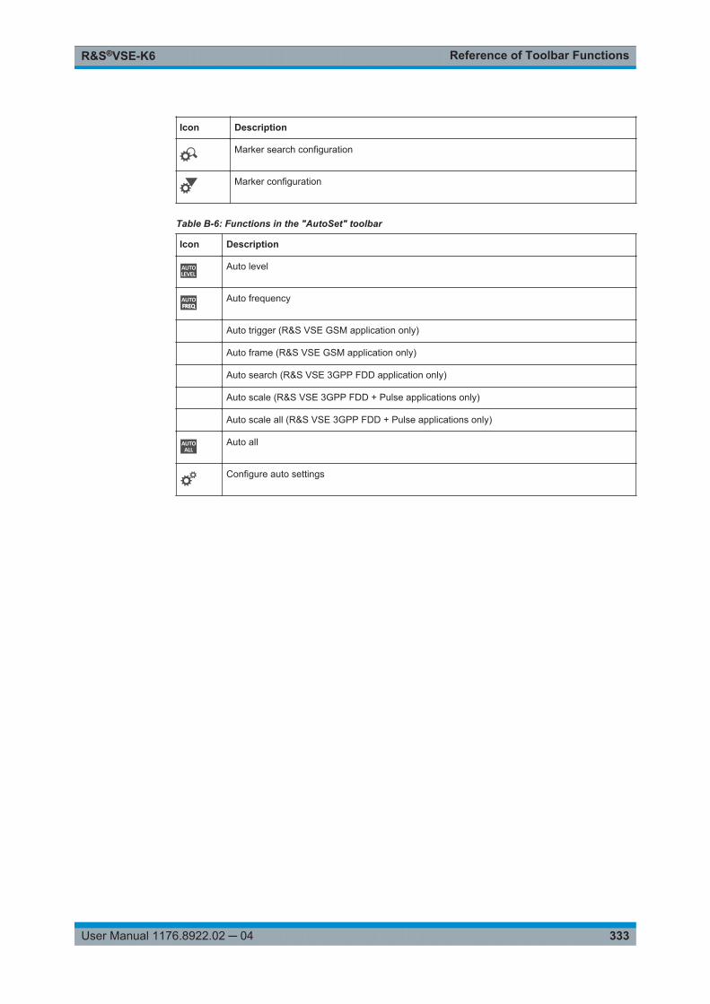
Reference of Toolbar FunctionsR&S®VSE-K6
333User Manual 1176.8922.02 ─ 04
Icon Description
Marker search configuration
Marker configuration
Table B-6: Functions in the "AutoSet" toolbar
Icon Description
Auto level
Auto frequency
Auto trigger (R&S VSE GSM application only)
Auto frame (R&S VSE GSM application only)
Auto search (R&S VSE 3GPP FDD application only)
Auto scale (R&S VSE 3GPP FDD + Pulse applications only)
Auto scale all (R&S VSE 3GPP FDD + Pulse applications only)
Auto all
Configure auto settings

Reference: ASCII File Export FormatR&S®VSE-K6
334User Manual 1176.8922.02 ─ 04
C Reference: ASCII File Export FormatTrace data can be exported to a file in ASCII format for further evaluation in otherapplications
The file consists of the header containing important scaling parameters and a data sec-tion containing the trace data.
Generally, the format of this ASCII file can be processed by spreadsheet calculationprograms, e.g. MS-Excel. Different language versions of evaluation programs mayrequire a different handling of the decimal point. Thus you can define the decimal sep-arator to be used (decimal point or comma, see " Decimal Separator " on page 90).
The data of the file header consist of three columns, each separated by a semicolon:parameter name; numeric value; basic unit. The data section starts with the two linescontaining the measured parameter names and units, followed by the measured datain multiple columns (depending on measurement) which are also separated by a semi-colon.
Table C-1: ASCII file format for table export
File contents Description
Header data
Type;R&S VSE; Instrument model
Version;5.00; Firmware version
Date;01.Oct 2006; Date of data set storage
Mode;PULSE; Application
Center Freq;55000;Hz Center frequency
Freq Offset;0;Hz Frequency offset
Meas BW;10000000,Hz Measurement Bandwidth
Filter Type;GAUS; Measurement filter type can be Gaussian (GAUS) or flat(FLAT)
Ref Level;-30;dBm Reference level
Level Offset;0;dB Level offset
Rf Att;20;dB Input attenuation
El Att;2.0;dB Electrical attenuation
SWT;0.005;s Sweep time (measurement time)
Sweep Count;20; Number of sweeps set
Preamplifier;OFF Preamplifier status
Top Pos.;CENT; Top (100%) level position can be Edge (EDGE) or Center(CENT)
Top Alg.;MEDI Top level measurement algorithm can be Median (MEDI) orMean (MEAN)
Ripple Portion;50;% Portion of pulse top where ripple is measured

Reference: ASCII File Export FormatR&S®VSE-K6
335User Manual 1176.8922.02 ─ 04
File contents Description
High Level;90;%V High (distal) threshold level
Mid Level;50;%V Mid (mesial) threshold level
Low Level;10;%V Low (proximal) threshold level
Boundary;3;%V The (top +/-) boundary level
Point Ref;CENT; Measurement point reference can be Rise (RISE), Center(CENT) or Fall (FALL)
Point Offset;0;s Measurement point offset
Range Ref;CENT; Measurement range reference can be Center (CENT) or Edge(EDGE)
Range Length;75;% Measurement range length (only valid for “Range Ref:;CENT”)
Range Offset Rise;0;s Measurement range offset from rising edge (only valid for“Range Ref:;EDGE”)
Range Offset Fall;0;s Measurement range offset from falling edge (only valid for“Range Ref:;EDGE”)
Data section
Values; 1001; Number of rows of measured values in the table
ID:;Pulse No.:;Rise Time:;… Pulse parameter names
Unit;;s;… Unit of pulse parameters
1;1;10.0e-9;…
2;2;10.1e-9;…
1;3;9.9e-9;…
…;…;…;…
Measured values: <ID>, <Pulse No.>, <Param 1>, … , <ParamN>

Effects of Large Gauss FiltersR&S®VSE-K6
336User Manual 1176.8922.02 ─ 04
D Effects of Large Gauss FiltersAs an alternative to the nearly rectangular "flat" measurement filters, the R&S VSEalso provides Gaussian filters. Gaussian filters have an optimized settling behavior,which avoids overshoot distortions in time domain data.
However, for Gaussian filters whose -3dB bandwidth is large compared to the maxi-mum I/Q bandwidth, the ideal Gaussian filter shape would exceed the maximum I/Qbandwidth at its outer edges. Thus, the actual filter only follows the ideal Gaussian filtershape in the inner range of the set I/Q bandwidth. At a certain frequency offset it mustdeviate from the ideal Gauss filter and drop off faster.
Gaussian filters with large -3dB bandwidths (<10 MHz)
Table D-1: Gauss filters with large -3 dB bandwidths
-3 dB BW Max. freq. withGaussian shape
Attenuation at max. freq. Attenuation at I/Q range edge (±40MHz)
40 MHz +/-24 MHz 4 dB > 60 dB
28 MHz +/-22 MHz 7 dB > 65 dB
18 MHz +/-28 MHz 29 dB > 100 dB
10 MHz +/-25 MHz 75 dB > 100 dB

List of Remote Commands (Pulse)R&S®VSE-K6
337User Manual 1176.8922.02 ─ 04
List of Remote Commands (Pulse)[SENSe:][WINDow<n>:]DETector<t>[:FUNCtion]..........................................................................................239[SENSe:][WINDow<n>:]DETector<t>[:FUNCtion]:AUTO...............................................................................240[SENSe:]AVERage<n>:COUNt......................................................................................................................238[SENSe:]AVERage<n>[:STATe<t>]...............................................................................................................239[SENSe:]BANDwidth:DEMod.........................................................................................................................142[SENSe:]BANDwidth:DEMod:TYPE.............................................................................................................. 142[SENSe:]BWIDth:DEMod...............................................................................................................................142[SENSe:]BWIDth:DEMod:TYPE.................................................................................................................... 142[SENSe:]DEMod:FMVF:TYPE.......................................................................................................................143[SENSe:]DETect:HYSTeresis........................................................................................................................144[SENSe:]DETect:LIMit................................................................................................................................... 144[SENSe:]DETect:LIMit:COUNt.......................................................................................................................144[SENSe:]DETect:REFerence.........................................................................................................................145[SENSe:]DETect:THReshold......................................................................................................................... 145[SENSe:]FREQuency:CENTer.......................................................................................................................128[SENSe:]FREQuency:CENTer:STEP............................................................................................................ 129[SENSe:]FREQuency:CENTer:STEP:AUTO................................................................................................. 129[SENSe:]FREQuency:OFFSet.......................................................................................................................130[SENSe:]PULSe:<Parametertype>:<Parameter>:LIMit?............................................................................... 311[SENSe:]PULSe:EMODel:FBPTime:AVERage?........................................................................................... 296[SENSe:]PULSe:EMODel:FBPTime:LIMit?................................................................................................... 311[SENSe:]PULSe:EMODel:FBPTime:MAXimum?...........................................................................................296[SENSe:]PULSe:EMODel:FBPTime:MINimum?............................................................................................296[SENSe:]PULSe:EMODel:FBPTime:SDEViation?.........................................................................................296[SENSe:]PULSe:EMODel:FBPTime?............................................................................................................ 296[SENSe:]PULSe:EMODel:FHPLevel:AVERage?...........................................................................................297[SENSe:]PULSe:EMODel:FHPLevel:LIMit?...................................................................................................311[SENSe:]PULSe:EMODel:FHPLevel:MAXimum?..........................................................................................297[SENSe:]PULSe:EMODel:FHPLevel:MINimum?...........................................................................................297[SENSe:]PULSe:EMODel:FHPLevel:SDEViation?........................................................................................297[SENSe:]PULSe:EMODel:FHPLevel?........................................................................................................... 296[SENSe:]PULSe:EMODel:FHPTime:AVERage?........................................................................................... 298[SENSe:]PULSe:EMODel:FHPTime:LIMit?................................................................................................... 311[SENSe:]PULSe:EMODel:FHPTime:MAXimum?.......................................................................................... 298[SENSe:]PULSe:EMODel:FHPTime:MINimum?............................................................................................298[SENSe:]PULSe:EMODel:FHPTime:SDEViation?.........................................................................................298[SENSe:]PULSe:EMODel:FHPTime?............................................................................................................297[SENSe:]PULSe:EMODel:FLPLevel:AVERage?........................................................................................... 298[SENSe:]PULSe:EMODel:FLPLevel:LIMit?................................................................................................... 311[SENSe:]PULSe:EMODel:FLPLevel:MAXimum?.......................................................................................... 298[SENSe:]PULSe:EMODel:FLPLevel:MINimum?............................................................................................298[SENSe:]PULSe:EMODel:FLPLevel:SDEViation?.........................................................................................298[SENSe:]PULSe:EMODel:FLPLevel?............................................................................................................298[SENSe:]PULSe:EMODel:FLPTime:AVERage?............................................................................................299[SENSe:]PULSe:EMODel:FLPTime:LIMit?....................................................................................................311[SENSe:]PULSe:EMODel:FLPTime:MAXimum?...........................................................................................299[SENSe:]PULSe:EMODel:FLPTime:MINimum?............................................................................................ 299

List of Remote Commands (Pulse)R&S®VSE-K6
338User Manual 1176.8922.02 ─ 04
[SENSe:]PULSe:EMODel:FLPTime:SDEViation?......................................................................................... 299[SENSe:]PULSe:EMODel:FLPTime?.............................................................................................................299[SENSe:]PULSe:EMODel:FMPLevel:AVERage?.......................................................................................... 300[SENSe:]PULSe:EMODel:FMPLevel:LIMit?.................................................................................................. 312[SENSe:]PULSe:EMODel:FMPLevel:MAXimum?......................................................................................... 300[SENSe:]PULSe:EMODel:FMPLevel:MINimum?...........................................................................................300[SENSe:]PULSe:EMODel:FMPLevel:SDEViation?........................................................................................300[SENSe:]PULSe:EMODel:FMPLevel?...........................................................................................................300[SENSe:]PULSe:EMODel:FMPTime:AVERage?...........................................................................................301[SENSe:]PULSe:EMODel:FMPTime:LIMit?...................................................................................................312[SENSe:]PULSe:EMODel:FMPTime:MAXimum?..........................................................................................301[SENSe:]PULSe:EMODel:FMPTime:MINimum?........................................................................................... 301[SENSe:]PULSe:EMODel:FMPTime:SDEViation?........................................................................................ 301[SENSe:]PULSe:EMODel:FMPTime?............................................................................................................300[SENSe:]PULSe:EMODel:FTPLevel:AVERage?...........................................................................................301[SENSe:]PULSe:EMODel:FTPLevel:LIMit?...................................................................................................312[SENSe:]PULSe:EMODel:FTPLevel:MAXimum?.......................................................................................... 301[SENSe:]PULSe:EMODel:FTPLevel:MINimum?........................................................................................... 301[SENSe:]PULSe:EMODel:FTPLevel:SDEViation?........................................................................................ 301[SENSe:]PULSe:EMODel:FTPLevel?............................................................................................................301[SENSe:]PULSe:EMODel:FTPTime:AVERage?............................................................................................302[SENSe:]PULSe:EMODel:FTPTime:LIMit?....................................................................................................312[SENSe:]PULSe:EMODel:FTPTime:MAXimum?...........................................................................................302[SENSe:]PULSe:EMODel:FTPTime:MINimum?............................................................................................302[SENSe:]PULSe:EMODel:FTPTime:SDEViation?.........................................................................................302[SENSe:]PULSe:EMODel:FTPTime?............................................................................................................ 302[SENSe:]PULSe:EMODel:RBPTime:AVERage?...........................................................................................303[SENSe:]PULSe:EMODel:RBPTime:LIMit?...................................................................................................312[SENSe:]PULSe:EMODel:RBPTime:MAXimum?.......................................................................................... 303[SENSe:]PULSe:EMODel:RBPTime:MINimum?........................................................................................... 303[SENSe:]PULSe:EMODel:RBPTime:SDEViation?........................................................................................ 303[SENSe:]PULSe:EMODel:RBPTime?............................................................................................................303[SENSe:]PULSe:EMODel:RHPLevel:AVERage?.......................................................................................... 304[SENSe:]PULSe:EMODel:RHPLevel:LIMit?.................................................................................................. 312[SENSe:]PULSe:EMODel:RHPLevel:MAXimum?......................................................................................... 304[SENSe:]PULSe:EMODel:RHPLevel:MINimum?...........................................................................................304[SENSe:]PULSe:EMODel:RHPLevel:SDEViation?........................................................................................304[SENSe:]PULSe:EMODel:RHPLevel?...........................................................................................................303[SENSe:]PULSe:EMODel:RHPTime:AVERage?...........................................................................................304[SENSe:]PULSe:EMODel:RHPTime:LIMit?...................................................................................................312[SENSe:]PULSe:EMODel:RHPTime:MAXimum?..........................................................................................304[SENSe:]PULSe:EMODel:RHPTime:MINimum?........................................................................................... 304[SENSe:]PULSe:EMODel:RHPTime:SDEViation?........................................................................................ 304[SENSe:]PULSe:EMODel:RHPTime?............................................................................................................304[SENSe:]PULSe:EMODel:RLPLevel:AVERage?...........................................................................................305[SENSe:]PULSe:EMODel:RLPLevel:LIMit?...................................................................................................312[SENSe:]PULSe:EMODel:RLPLevel:MAXimum?..........................................................................................305[SENSe:]PULSe:EMODel:RLPLevel:MINimum?........................................................................................... 305[SENSe:]PULSe:EMODel:RLPLevel:SDEViation?........................................................................................ 305[SENSe:]PULSe:EMODel:RLPLevel?............................................................................................................305

List of Remote Commands (Pulse)R&S®VSE-K6
339User Manual 1176.8922.02 ─ 04
[SENSe:]PULSe:EMODel:RLPTime:AVERage?........................................................................................... 306[SENSe:]PULSe:EMODel:RLPTime:LIMit?................................................................................................... 312[SENSe:]PULSe:EMODel:RLPTime:MAXimum?...........................................................................................306[SENSe:]PULSe:EMODel:RLPTime:MINimum?............................................................................................306[SENSe:]PULSe:EMODel:RLPTime:SDEViation?.........................................................................................306[SENSe:]PULSe:EMODel:RLPTime?............................................................................................................ 306[SENSe:]PULSe:EMODel:RMPLevel:AVERage?..........................................................................................307[SENSe:]PULSe:EMODel:RMPLevel:LIMit?..................................................................................................312[SENSe:]PULSe:EMODel:RMPLevel:MAXimum?.........................................................................................307[SENSe:]PULSe:EMODel:RMPLevel:MINimum?.......................................................................................... 307[SENSe:]PULSe:EMODel:RMPLevel:SDEViation?....................................................................................... 307[SENSe:]PULSe:EMODel:RMPLevel?...........................................................................................................306[SENSe:]PULSe:EMODel:RMPTime:AVERage?.......................................................................................... 307[SENSe:]PULSe:EMODel:RMPTime:LIMit?.................................................................................................. 312[SENSe:]PULSe:EMODel:RMPTime:MAXimum?..........................................................................................307[SENSe:]PULSe:EMODel:RMPTime:MINimum?...........................................................................................307[SENSe:]PULSe:EMODel:RMPTime:SDEViation?........................................................................................307[SENSe:]PULSe:EMODel:RMPTime?........................................................................................................... 307[SENSe:]PULSe:EMODel:RTPLevel:AVERage?...........................................................................................308[SENSe:]PULSe:EMODel:RTPLevel:LIMit?...................................................................................................312[SENSe:]PULSe:EMODel:RTPLevel:MAXimum?..........................................................................................308[SENSe:]PULSe:EMODel:RTPLevel:MINimum?...........................................................................................308[SENSe:]PULSe:EMODel:RTPLevel:SDEViation?........................................................................................308[SENSe:]PULSe:EMODel:RTPLevel?........................................................................................................... 308[SENSe:]PULSe:EMODel:RTPTime:AVERage?........................................................................................... 309[SENSe:]PULSe:EMODel:RTPTime:LIMit?................................................................................................... 312[SENSe:]PULSe:EMODel:RTPTime:MAXimum?.......................................................................................... 309[SENSe:]PULSe:EMODel:RTPTime:MINimum?............................................................................................309[SENSe:]PULSe:EMODel:RTPTime:SDEViation?.........................................................................................309[SENSe:]PULSe:EMODel:RTPTime?............................................................................................................309[SENSe:]PULSe:FREQuency:CRATe:AVERage?.........................................................................................285[SENSe:]PULSe:FREQuency:CRATe:LIMit?.................................................................................................312[SENSe:]PULSe:FREQuency:CRATe:MAXimum?........................................................................................285[SENSe:]PULSe:FREQuency:CRATe:MINimum?.........................................................................................285[SENSe:]PULSe:FREQuency:CRATe:SDEViation?......................................................................................285[SENSe:]PULSe:FREQuency:CRATe?......................................................................................................... 285[SENSe:]PULSe:FREQuency:DEViation:AVERage?.................................................................................... 286[SENSe:]PULSe:FREQuency:DEViation:LIMit?............................................................................................ 312[SENSe:]PULSe:FREQuency:DEViation:MAXimum?....................................................................................286[SENSe:]PULSe:FREQuency:DEViation:MINimum?.....................................................................................286[SENSe:]PULSe:FREQuency:DEViation:SDEViation?..................................................................................286[SENSe:]PULSe:FREQuency:DEViation?..................................................................................................... 285[SENSe:]PULSe:FREQuency:PERRor:AVERage?....................................................................................... 286[SENSe:]PULSe:FREQuency:PERRor:LIMit?............................................................................................... 312[SENSe:]PULSe:FREQuency:PERRor:MAXimum?...................................................................................... 286[SENSe:]PULSe:FREQuency:PERRor:MINimum?........................................................................................286[SENSe:]PULSe:FREQuency:PERRor:SDEViation?.....................................................................................286[SENSe:]PULSe:FREQuency:PERRor?........................................................................................................286[SENSe:]PULSe:FREQuency:POINt:AVERage?...........................................................................................287[SENSe:]PULSe:FREQuency:POINt:LIMit?...................................................................................................312

List of Remote Commands (Pulse)R&S®VSE-K6
340User Manual 1176.8922.02 ─ 04
[SENSe:]PULSe:FREQuency:POINt:MAXimum?..........................................................................................287[SENSe:]PULSe:FREQuency:POINt:MINimum?...........................................................................................287[SENSe:]PULSe:FREQuency:POINt:SDEViation?........................................................................................287[SENSe:]PULSe:FREQuency:POINt?........................................................................................................... 287[SENSe:]PULSe:FREQuency:PPFRequency:AVERage?............................................................................. 288[SENSe:]PULSe:FREQuency:PPFRequency:LIMit?..................................................................................... 312[SENSe:]PULSe:FREQuency:PPFRequency:MAXimum?............................................................................ 288[SENSe:]PULSe:FREQuency:PPFRequency:MINimum?..............................................................................288[SENSe:]PULSe:FREQuency:PPFRequency:SDEViation?...........................................................................288[SENSe:]PULSe:FREQuency:PPFRequency?..............................................................................................288[SENSe:]PULSe:FREQuency:RERRor:AVERage?.......................................................................................289[SENSe:]PULSe:FREQuency:RERRor:LIMit?...............................................................................................312[SENSe:]PULSe:FREQuency:RERRor:MAXimum?...................................................................................... 289[SENSe:]PULSe:FREQuency:RERRor:MINimum?....................................................................................... 289[SENSe:]PULSe:FREQuency:RERRor:SDEViation?.................................................................................... 289[SENSe:]PULSe:FREQuency:RERRor?........................................................................................................288[SENSe:]PULSe:ID?...................................................................................................................................... 256[SENSe:]PULSe:NUMBer?............................................................................................................................256[SENSe:]PULSe:PHASe:DEViation:AVERage?............................................................................................ 290[SENSe:]PULSe:PHASe:DEViation:LIMit?.................................................................................................... 312[SENSe:]PULSe:PHASe:DEViation:MAXimum?........................................................................................... 290[SENSe:]PULSe:PHASe:DEViation:MINimum?.............................................................................................290[SENSe:]PULSe:PHASe:DEViation:SDEViation?..........................................................................................290[SENSe:]PULSe:PHASe:DEViation?.............................................................................................................290[SENSe:]PULSe:PHASe:PERRor:AVERage?...............................................................................................291[SENSe:]PULSe:PHASe:PERRor:LIMit?.......................................................................................................312[SENSe:]PULSe:PHASe:PERRor:MAXimum?.............................................................................................. 291[SENSe:]PULSe:PHASe:PERRor:MINimum?............................................................................................... 291[SENSe:]PULSe:PHASe:PERRor:SDEViation?............................................................................................ 291[SENSe:]PULSe:PHASe:PERRor?................................................................................................................291[SENSe:]PULSe:PHASe:POINt:AVERage?.................................................................................................. 292[SENSe:]PULSe:PHASe:POINt:LIMit?.......................................................................................................... 312[SENSe:]PULSe:PHASe:POINt:MAXimum?..................................................................................................292[SENSe:]PULSe:PHASe:POINt:MINimum?...................................................................................................292[SENSe:]PULSe:PHASe:POINt:SDEViation?................................................................................................292[SENSe:]PULSe:PHASe:POINt?................................................................................................................... 291[SENSe:]PULSe:PHASe:PPPHase:AVERage?.............................................................................................293[SENSe:]PULSe:PHASe:PPPHase:LIMit?.....................................................................................................312[SENSe:]PULSe:PHASe:PPPHase:MAXimum?............................................................................................293[SENSe:]PULSe:PHASe:PPPHase:MINimum?.............................................................................................293[SENSe:]PULSe:PHASe:PPPHase:SDEViation?..........................................................................................293[SENSe:]PULSe:PHASe:PPPHase?............................................................................................................. 292[SENSe:]PULSe:PHASe:RERRor:AVERage?...............................................................................................293[SENSe:]PULSe:PHASe:RERRor:LIMit?.......................................................................................................312[SENSe:]PULSe:PHASe:RERRor:MAXimum?..............................................................................................293[SENSe:]PULSe:PHASe:RERRor:MINimum?............................................................................................... 293[SENSe:]PULSe:PHASe:RERRor:SDEViation?............................................................................................ 293[SENSe:]PULSe:PHASe:RERRor?................................................................................................................293[SENSe:]PULSe:POWer:ADRoop:DB:AVERage?.........................................................................................260[SENSe:]PULSe:POWer:ADRoop:DB:LIMit?.................................................................................................312

List of Remote Commands (Pulse)R&S®VSE-K6
341User Manual 1176.8922.02 ─ 04
[SENSe:]PULSe:POWer:ADRoop:DB:MAXimum?........................................................................................260[SENSe:]PULSe:POWer:ADRoop:DB:MINimum?.........................................................................................260[SENSe:]PULSe:POWer:ADRoop:DB:SDEViation?......................................................................................260[SENSe:]PULSe:POWer:ADRoop:DB?......................................................................................................... 259[SENSe:]PULSe:POWer:ADRoop[:PERCent]:AVERage?.............................................................................260[SENSe:]PULSe:POWer:ADRoop[:PERCent]:LIMit?.....................................................................................312[SENSe:]PULSe:POWer:ADRoop[:PERCent]:MAXimum?............................................................................260[SENSe:]PULSe:POWer:ADRoop[:PERCent]:MINimum?.............................................................................260[SENSe:]PULSe:POWer:ADRoop[:PERCent]:SDEViation?..........................................................................260[SENSe:]PULSe:POWer:ADRoop[:PERCent]?............................................................................................. 260[SENSe:]PULSe:POWer:AMPLitude:AVERage?...........................................................................................261[SENSe:]PULSe:POWer:AMPLitude:I:AVERage?.........................................................................................262[SENSe:]PULSe:POWer:AMPLitude:I:LIMit?.................................................................................................312[SENSe:]PULSe:POWer:AMPLitude:I:MAXimum?........................................................................................262[SENSe:]PULSe:POWer:AMPLitude:I:MINimum?.........................................................................................262[SENSe:]PULSe:POWer:AMPLitude:I:SDEViation?......................................................................................262[SENSe:]PULSe:POWer:AMPLitude:I?......................................................................................................... 262[SENSe:]PULSe:POWer:AMPLitude:LIMit?...................................................................................................312[SENSe:]PULSe:POWer:AMPLitude:MAXimum?..........................................................................................261[SENSe:]PULSe:POWer:AMPLitude:MINimum?...........................................................................................261[SENSe:]PULSe:POWer:AMPLitude:Q:AVERage?.......................................................................................263[SENSe:]PULSe:POWer:AMPLitude:Q:LIMit?...............................................................................................312[SENSe:]PULSe:POWer:AMPLitude:Q:MAXimum?......................................................................................263[SENSe:]PULSe:POWer:AMPLitude:Q:MINimum?....................................................................................... 263[SENSe:]PULSe:POWer:AMPLitude:Q:SDEViation?.................................................................................... 263[SENSe:]PULSe:POWer:AMPLitude:Q?........................................................................................................262[SENSe:]PULSe:POWer:AMPLitude:SDEViation?........................................................................................261[SENSe:]PULSe:POWer:AMPLitude?........................................................................................................... 261[SENSe:]PULSe:POWer:AVG:AVERage?.....................................................................................................263[SENSe:]PULSe:POWer:AVG:LIMit?.............................................................................................................312[SENSe:]PULSe:POWer:AVG:MAXimum?....................................................................................................263[SENSe:]PULSe:POWer:AVG:MINimum?.....................................................................................................264[SENSe:]PULSe:POWer:AVG:SDEViation?..................................................................................................264[SENSe:]PULSe:POWer:AVG?..................................................................................................................... 263[SENSe:]PULSe:POWer:BASE:AVERage?...................................................................................................264[SENSe:]PULSe:POWer:BASE:LIMit?...........................................................................................................312[SENSe:]PULSe:POWer:BASE:MAXimum?..................................................................................................264[SENSe:]PULSe:POWer:BASE:MINimum?...................................................................................................264[SENSe:]PULSe:POWer:BASE:SDEViation?................................................................................................264[SENSe:]PULSe:POWer:BASE?................................................................................................................... 264[SENSe:]PULSe:POWer:MAX:AVERage?.................................................................................................... 265[SENSe:]PULSe:POWer:MAX:LIMit?............................................................................................................ 312[SENSe:]PULSe:POWer:MAX:MAXimum?....................................................................................................265[SENSe:]PULSe:POWer:MAX:MINimum?.....................................................................................................265[SENSe:]PULSe:POWer:MAX:SDEViation?..................................................................................................265[SENSe:]PULSe:POWer:MAX?..................................................................................................................... 265[SENSe:]PULSe:POWer:MIN:AVERage?......................................................................................................266[SENSe:]PULSe:POWer:MIN:LIMit?..............................................................................................................312[SENSe:]PULSe:POWer:MIN:MAXimum?.....................................................................................................266[SENSe:]PULSe:POWer:MIN:MINimum?......................................................................................................266

List of Remote Commands (Pulse)R&S®VSE-K6
342User Manual 1176.8922.02 ─ 04
[SENSe:]PULSe:POWer:MIN:SDEViation?...................................................................................................266[SENSe:]PULSe:POWer:MIN?...................................................................................................................... 265[SENSe:]PULSe:POWer:ON:AVERage?.......................................................................................................267[SENSe:]PULSe:POWer:ON:LIMit?...............................................................................................................312[SENSe:]PULSe:POWer:ON:MAXimum?......................................................................................................267[SENSe:]PULSe:POWer:ON:MINimum?....................................................................................................... 267[SENSe:]PULSe:POWer:ON:SDEViation?.................................................................................................... 267[SENSe:]PULSe:POWer:ON?........................................................................................................................266[SENSe:]PULSe:POWer:OVERshoot:DB:AVERage?................................................................................... 267[SENSe:]PULSe:POWer:OVERshoot:DB:LIMit?........................................................................................... 312[SENSe:]PULSe:POWer:OVERshoot:DB:MAXimum?.................................................................................. 267[SENSe:]PULSe:POWer:OVERshoot:DB:MINimum?....................................................................................267[SENSe:]PULSe:POWer:OVERshoot:DB:SDEViation?.................................................................................267[SENSe:]PULSe:POWer:OVERshoot:DB?....................................................................................................267[SENSe:]PULSe:POWer:OVERshoot[:PERCent]:AVERage?....................................................................... 268[SENSe:]PULSe:POWer:OVERshoot[:PERCent]:LIMit?............................................................................... 312[SENSe:]PULSe:POWer:OVERshoot[:PERCent]:MAXimum?...................................................................... 268[SENSe:]PULSe:POWer:OVERshoot[:PERCent]:MINimum?........................................................................268[SENSe:]PULSe:POWer:OVERshoot[:PERCent]:SDEViation?.....................................................................268[SENSe:]PULSe:POWer:OVERshoot[:PERCent]?........................................................................................268[SENSe:]PULSe:POWer:PAVG:AVERage?.................................................................................................. 269[SENSe:]PULSe:POWer:PAVG:LIMit?.......................................................................................................... 312[SENSe:]PULSe:POWer:PAVG:MAXimum?................................................................................................. 269[SENSe:]PULSe:POWer:PAVG:MINimum?...................................................................................................269[SENSe:]PULSe:POWer:PAVG:SDEViation?................................................................................................269[SENSe:]PULSe:POWer:PAVG?...................................................................................................................269[SENSe:]PULSe:POWer:PMIN:AVERage?................................................................................................... 270[SENSe:]PULSe:POWer:PMIN:LIMit?........................................................................................................... 312[SENSe:]PULSe:POWer:PMIN:MAXimum?.................................................................................................. 270[SENSe:]PULSe:POWer:PMIN:MINimum?....................................................................................................270[SENSe:]PULSe:POWer:PMIN:SDEViation?.................................................................................................270[SENSe:]PULSe:POWer:PMIN?....................................................................................................................269[SENSe:]PULSe:POWer:POINt:AVERage?.................................................................................................. 271[SENSe:]PULSe:POWer:POINt:LIMit?.......................................................................................................... 312[SENSe:]PULSe:POWer:POINt:MAXimum?..................................................................................................271[SENSe:]PULSe:POWer:POINt:MINimum?...................................................................................................271[SENSe:]PULSe:POWer:POINt:SDEViation?................................................................................................271[SENSe:]PULSe:POWer:POINt?................................................................................................................... 270[SENSe:]PULSe:POWer:PON:AVERage?.................................................................................................... 271[SENSe:]PULSe:POWer:PON:LIMit?............................................................................................................ 312[SENSe:]PULSe:POWer:PON:MAXimum?....................................................................................................271[SENSe:]PULSe:POWer:PON:MINimum?.....................................................................................................271[SENSe:]PULSe:POWer:PON:SDEViation?..................................................................................................271[SENSe:]PULSe:POWer:PON?..................................................................................................................... 271[SENSe:]PULSe:POWer:PPRatio:AVERage?...............................................................................................272[SENSe:]PULSe:POWer:PPRatio:LIMit?.......................................................................................................312[SENSe:]PULSe:POWer:PPRatio:MAXimum?.............................................................................................. 272[SENSe:]PULSe:POWer:PPRatio:MINimum?............................................................................................... 272[SENSe:]PULSe:POWer:PPRatio:SDEViation?............................................................................................ 272[SENSe:]PULSe:POWer:PPRatio?................................................................................................................272

List of Remote Commands (Pulse)R&S®VSE-K6
343User Manual 1176.8922.02 ─ 04
[SENSe:]PULSe:POWer:RIPPle:DB:AVERage?...........................................................................................273[SENSe:]PULSe:POWer:RIPPle:DB:LIMit?...................................................................................................312[SENSe:]PULSe:POWer:RIPPle:DB:MAXimum?.......................................................................................... 273[SENSe:]PULSe:POWer:RIPPle:DB:MINimum?........................................................................................... 273[SENSe:]PULSe:POWer:RIPPle:DB:SDEViation?........................................................................................ 273[SENSe:]PULSe:POWer:RIPPle:DB?............................................................................................................273[SENSe:]PULSe:POWer:RIPPle[:PERCent]:AVERage?...............................................................................274[SENSe:]PULSe:POWer:RIPPle[:PERCent]:LIMit?.......................................................................................312[SENSe:]PULSe:POWer:RIPPle[:PERCent]:MAXimum?.............................................................................. 274[SENSe:]PULSe:POWer:RIPPle[:PERCent]:MINimum?............................................................................... 274[SENSe:]PULSe:POWer:RIPPle[:PERCent]:SDEViation?............................................................................ 274[SENSe:]PULSe:POWer:RIPPle[:PERCent]?................................................................................................273[SENSe:]PULSe:POWer:TOP:AVERage?.....................................................................................................274[SENSe:]PULSe:POWer:TOP:LIMit?.............................................................................................................312[SENSe:]PULSe:POWer:TOP:MAXimum?....................................................................................................274[SENSe:]PULSe:POWer:TOP:MINimum?..................................................................................................... 274[SENSe:]PULSe:POWer:TOP:SDEViation?.................................................................................................. 274[SENSe:]PULSe:POWer:TOP?......................................................................................................................274[SENSe:]PULSe:TIMing:DCYCle:AVERage?................................................................................................276[SENSe:]PULSe:TIMing:DCYCle:LIMit?........................................................................................................312[SENSe:]PULSe:TIMing:DCYCle:MAXimum?............................................................................................... 276[SENSe:]PULSe:TIMing:DCYCle:MINimum?................................................................................................ 276[SENSe:]PULSe:TIMing:DCYCle:SDEViation?............................................................................................. 276[SENSe:]PULSe:TIMing:DCYCle?.................................................................................................................276[SENSe:]PULSe:TIMing:DRATio:AVERage?................................................................................................ 277[SENSe:]PULSe:TIMing:DRATio:LIMit?........................................................................................................ 312[SENSe:]PULSe:TIMing:DRATio:MAXimum?................................................................................................277[SENSe:]PULSe:TIMing:DRATio:MINimum?.................................................................................................277[SENSe:]PULSe:TIMing:DRATio:SDEViation?..............................................................................................277[SENSe:]PULSe:TIMing:DRATio?................................................................................................................. 277[SENSe:]PULSe:TIMing:FALL:AVERage?.................................................................................................... 278[SENSe:]PULSe:TIMing:FALL:LIMit?............................................................................................................ 312[SENSe:]PULSe:TIMing:FALL:MAXimum?....................................................................................................278[SENSe:]PULSe:TIMing:FALL:MINimum?.....................................................................................................278[SENSe:]PULSe:TIMing:FALL:SDEViation?..................................................................................................278[SENSe:]PULSe:TIMing:FALL?..................................................................................................................... 278[SENSe:]PULSe:TIMing:OFF:AVERage?......................................................................................................279[SENSe:]PULSe:TIMing:OFF:LIMit?..............................................................................................................312[SENSe:]PULSe:TIMing:OFF:MAXimum?.....................................................................................................279[SENSe:]PULSe:TIMing:OFF:MINimum?...................................................................................................... 279[SENSe:]PULSe:TIMing:OFF:SDEViation?................................................................................................... 279[SENSe:]PULSe:TIMing:OFF?.......................................................................................................................278[SENSe:]PULSe:TIMing:PRF:AVERage?......................................................................................................279[SENSe:]PULSe:TIMing:PRF:LIMit?..............................................................................................................312[SENSe:]PULSe:TIMing:PRF:MAXimum?.....................................................................................................279[SENSe:]PULSe:TIMing:PRF:MINimum?...................................................................................................... 280[SENSe:]PULSe:TIMing:PRF:SDEViation?................................................................................................... 280[SENSe:]PULSe:TIMing:PRF?.......................................................................................................................279[SENSe:]PULSe:TIMing:PRI:AVERage?.......................................................................................................280[SENSe:]PULSe:TIMing:PRI:LIMit?...............................................................................................................312

List of Remote Commands (Pulse)R&S®VSE-K6
344User Manual 1176.8922.02 ─ 04
[SENSe:]PULSe:TIMing:PRI:MAXimum?...................................................................................................... 280[SENSe:]PULSe:TIMing:PRI:MINimum?....................................................................................................... 280[SENSe:]PULSe:TIMing:PRI:SDEViation?.................................................................................................... 280[SENSe:]PULSe:TIMing:PRI?........................................................................................................................280[SENSe:]PULSe:TIMing:PWIDth:AVERage?.................................................................................................281[SENSe:]PULSe:TIMing:PWIDth:LIMit?.........................................................................................................313[SENSe:]PULSe:TIMing:PWIDth:MAXimum?................................................................................................281[SENSe:]PULSe:TIMing:PWIDth:MINimum?.................................................................................................281[SENSe:]PULSe:TIMing:PWIDth:SDEViation?..............................................................................................281[SENSe:]PULSe:TIMing:PWIDth?................................................................................................................. 281[SENSe:]PULSe:TIMing:RISE:AVERage?.....................................................................................................282[SENSe:]PULSe:TIMing:RISE:LIMit?.............................................................................................................313[SENSe:]PULSe:TIMing:RISE:MAXimum?....................................................................................................282[SENSe:]PULSe:TIMing:RISE:MINimum?.....................................................................................................282[SENSe:]PULSe:TIMing:RISE:SDEViation?..................................................................................................282[SENSe:]PULSe:TIMing:RISE?..................................................................................................................... 281[SENSe:]PULSe:TIMing:SETTling:AVERage?.............................................................................................. 283[SENSe:]PULSe:TIMing:SETTling:LIMit?...................................................................................................... 313[SENSe:]PULSe:TIMing:SETTling:MAXimum?............................................................................................. 283[SENSe:]PULSe:TIMing:SETTling:MINimum?...............................................................................................283[SENSe:]PULSe:TIMing:SETTling:SDEViation?............................................................................................283[SENSe:]PULSe:TIMing:SETTling?...............................................................................................................282[SENSe:]PULSe:TIMing:TSTamp:AVERage?............................................................................................... 283[SENSe:]PULSe:TIMing:TSTamp:LIMit?....................................................................................................... 313[SENSe:]PULSe:TIMing:TSTamp:MAXimum?.............................................................................................. 283[SENSe:]PULSe:TIMing:TSTamp:MINimum?................................................................................................283[SENSe:]PULSe:TIMing:TSTamp:SDEViation?.............................................................................................283[SENSe:]PULSe:TIMing:TSTamp?................................................................................................................283[SENSe:]SRATe?...........................................................................................................................................143[SENSe:]STATistic<n>:TYPE........................................................................................................................ 240[SENSe:]SWEep:COUNt............................................................................................................................... 238[SENSe:]SWEep:POINts............................................................................................................................... 240[SENSe:]SWEep:TIME.................................................................................................................................. 143CALCulate<n>:DELTamarker<m>:AOFF...................................................................................................... 243CALCulate<n>:DELTamarker<m>:LINK........................................................................................................243CALCulate<n>:DELTamarker<m>:LINK:TO:MARKer<m>............................................................................244CALCulate<n>:DELTamarker<m>:MAXimum:LEFT..................................................................................... 250CALCulate<n>:DELTamarker<m>:MAXimum:NEXT.....................................................................................250CALCulate<n>:DELTamarker<m>:MAXimum:RIGHt.................................................................................... 251CALCulate<n>:DELTamarker<m>:MAXimum[:PEAK]...................................................................................250CALCulate<n>:DELTamarker<m>:MINimum:LEFT.......................................................................................251CALCulate<n>:DELTamarker<m>:MINimum:NEXT......................................................................................251CALCulate<n>:DELTamarker<m>:MINimum:RIGHt..................................................................................... 252CALCulate<n>:DELTamarker<m>:MINimum[:PEAK]....................................................................................251CALCulate<n>:DELTamarker<m>:MREFerence...........................................................................................244CALCulate<n>:DELTamarker<m>:TRACe....................................................................................................245CALCulate<n>:DELTamarker<m>:X............................................................................................................. 245CALCulate<n>:DELTamarker<m>:X:RELative?............................................................................................317CALCulate<n>:DELTamarker<m>:Y?........................................................................................................... 317CALCulate<n>:DELTamarker<m>[:STATe]...................................................................................................244

List of Remote Commands (Pulse)R&S®VSE-K6
345User Manual 1176.8922.02 ─ 04
CALCulate<n>:DISTribution:EMODel............................................................................................................164CALCulate<n>:DISTribution:FREQuency......................................................................................................166CALCulate<n>:DISTribution:LLINes[:STATe]................................................................................................167CALCulate<n>:DISTribution:NBINs...............................................................................................................167CALCulate<n>:DISTribution:PHASe..............................................................................................................167CALCulate<n>:DISTribution:POWer..............................................................................................................168CALCulate<n>:DISTribution:TIMing.............................................................................................................. 170CALCulate<n>:MARKer<m>:AOFF...............................................................................................................241CALCulate<n>:MARKer<m>:LINK.................................................................................................................246CALCulate<n>:MARKer<m>:LINK:TO:MARKer<m>.....................................................................................241CALCulate<n>:MARKer<m>:LINK:TRENd....................................................................................................246CALCulate<n>:MARKer<m>:MAXimum:LEFT.............................................................................................. 248CALCulate<n>:MARKer<m>:MAXimum:NEXT............................................................................................. 248CALCulate<n>:MARKer<m>:MAXimum:RIGHt.............................................................................................248CALCulate<n>:MARKer<m>:MAXimum[:PEAK]........................................................................................... 248CALCulate<n>:MARKer<m>:MINimum:LEFT............................................................................................... 249CALCulate<n>:MARKer<m>:MINimum:NEXT...............................................................................................249CALCulate<n>:MARKer<m>:MINimum:RIGHt.............................................................................................. 249CALCulate<n>:MARKer<m>:MINimum[:PEAK].............................................................................................249CALCulate<n>:MARKer<m>:PEXCursion.....................................................................................................247CALCulate<n>:MARKer<m>:TRACe.............................................................................................................242CALCulate<n>:MARKer<m>:X...................................................................................................................... 242CALCulate<n>:MARKer<m>:Y?.................................................................................................................... 318CALCulate<n>:MARKer<m>[:STATe]........................................................................................................... 242CALCulate<n>:PSPectrum:AUTO................................................................................................................. 171CALCulate<n>:PSPectrum:BLOCksize......................................................................................................... 172CALCulate<n>:PSPectrum:EMODel..............................................................................................................172CALCulate<n>:PSPectrum:FREQuency........................................................................................................173CALCulate<n>:PSPectrum:GTHReshold...................................................................................................... 174CALCulate<n>:PSPectrum:MAXFrequency.................................................................................................. 174CALCulate<n>:PSPectrum:PHASe............................................................................................................... 175CALCulate<n>:PSPectrum:POWer............................................................................................................... 175CALCulate<n>:PSPectrum:RBW?.................................................................................................................177CALCulate<n>:PSPectrum:STHReshold.......................................................................................................177CALCulate<n>:PSPectrum:TIMing................................................................................................................ 177CALCulate<n>:PSPectrum:WINDow.............................................................................................................178CALCulate<n>:RRSPectrum:AUTO.............................................................................................................. 208CALCulate<n>:RRSPectrum:RBW................................................................................................................208CALCulate<n>:RRSPectrum:WINDow.......................................................................................................... 207CALCulate<n>:TABLe:<ParameterGroup>:<Parameter>:LIMit.....................................................................229CALCulate<n>:TABLe:<ParameterGroup>:<Parameter>:LIMit:STATe........................................................ 227CALCulate<n>:TABLe:<ParameterGroup>:ALL:LIMit:STATe.......................................................................229CALCulate<n>:TABLe:ALL:LIMit:STATe.......................................................................................................229CALCulate<n>:TABLe:EMODel:ALL:LIMit:STATe........................................................................................ 229CALCulate<n>:TABLe:EMODel:ALL[:STATe]............................................................................................... 210CALCulate<n>:TABLe:EMODel:FBPTime.....................................................................................................210CALCulate<n>:TABLe:EMODel:FBPTime:LIMit............................................................................................229CALCulate<n>:TABLe:EMODel:FBPTime:LIMit:STATe................................................................................227CALCulate<n>:TABLe:EMODel:FHPLevel....................................................................................................210CALCulate<n>:TABLe:EMODel:FHPLevel:LIMit........................................................................................... 230

List of Remote Commands (Pulse)R&S®VSE-K6
346User Manual 1176.8922.02 ─ 04
CALCulate<n>:TABLe:EMODel:FHPLevel:LIMit:STATe...............................................................................227CALCulate<n>:TABLe:EMODel:FHPTime.....................................................................................................211CALCulate<n>:TABLe:EMODel:FHPTime:LIMit............................................................................................230CALCulate<n>:TABLe:EMODel:FHPTime:LIMit:STATe................................................................................227CALCulate<n>:TABLe:EMODel:FLPLevel.....................................................................................................211CALCulate<n>:TABLe:EMODel:FLPLevel:LIMit............................................................................................230CALCulate<n>:TABLe:EMODel:FLPLevel:LIMit:STATe................................................................................227CALCulate<n>:TABLe:EMODel:FLPTime..................................................................................................... 211CALCulate<n>:TABLe:EMODel:FLPTime:LIMit............................................................................................ 230CALCulate<n>:TABLe:EMODel:FLPTime:LIMit:STATe................................................................................ 227CALCulate<n>:TABLe:EMODel:FMPLevel....................................................................................................211CALCulate<n>:TABLe:EMODel:FMPLevel:LIMit...........................................................................................230CALCulate<n>:TABLe:EMODel:FMPLevel:LIMit:STATe...............................................................................227CALCulate<n>:TABLe:EMODel:FMPTime.................................................................................................... 212CALCulate<n>:TABLe:EMODel:FMPTime:LIMit........................................................................................... 230CALCulate<n>:TABLe:EMODel:FMPTime:LIMit:STATe............................................................................... 227CALCulate<n>:TABLe:EMODel:FTPLevel.................................................................................................... 212CALCulate<n>:TABLe:EMODel:FTPLevel:LIMit............................................................................................230CALCulate<n>:TABLe:EMODel:FTPLevel:LIMit:STATe............................................................................... 227CALCulate<n>:TABLe:EMODel:FTPTime.....................................................................................................212CALCulate<n>:TABLe:EMODel:FTPTime:LIMit............................................................................................ 230CALCulate<n>:TABLe:EMODel:FTPTime:LIMit:STATe................................................................................227CALCulate<n>:TABLe:EMODel:RBPTime.................................................................................................... 213CALCulate<n>:TABLe:EMODel:RBPTime:LIMit............................................................................................230CALCulate<n>:TABLe:EMODel:RBPTime:LIMit:STATe............................................................................... 227CALCulate<n>:TABLe:EMODel:RHPLevel....................................................................................................213CALCulate<n>:TABLe:EMODel:RHPLevel:LIMit...........................................................................................230CALCulate<n>:TABLe:EMODel:RHPLevel:LIMit:STATe...............................................................................227CALCulate<n>:TABLe:EMODel:RHPTime.................................................................................................... 213CALCulate<n>:TABLe:EMODel:RHPTime:LIMit........................................................................................... 230CALCulate<n>:TABLe:EMODel:RHPTime:LIMit:STATe............................................................................... 227CALCulate<n>:TABLe:EMODel:RLPLevel.................................................................................................... 213CALCulate<n>:TABLe:EMODel:RLPLevel:LIMit........................................................................................... 230CALCulate<n>:TABLe:EMODel:RLPLevel:LIMit:STATe............................................................................... 228CALCulate<n>:TABLe:EMODel:RLPTime.....................................................................................................214CALCulate<n>:TABLe:EMODel:RLPTime:LIMit............................................................................................230CALCulate<n>:TABLe:EMODel:RLPTime:LIMit:STATe................................................................................228CALCulate<n>:TABLe:EMODel:RMPLevel................................................................................................... 214CALCulate<n>:TABLe:EMODel:RMPLevel:LIMit.......................................................................................... 230CALCulate<n>:TABLe:EMODel:RMPLevel:LIMit:STATe.............................................................................. 228CALCulate<n>:TABLe:EMODel:RMPTime....................................................................................................214CALCulate<n>:TABLe:EMODel:RMPTime:LIMit...........................................................................................230CALCulate<n>:TABLe:EMODel:RMPTime:LIMit:STATe...............................................................................228CALCulate<n>:TABLe:EMODel:RTPLevel....................................................................................................214CALCulate<n>:TABLe:EMODel:RTPLevel:LIMit........................................................................................... 230CALCulate<n>:TABLe:EMODel:RTPLevel:LIMit:STATe...............................................................................228CALCulate<n>:TABLe:EMODel:RTPTime.....................................................................................................215CALCulate<n>:TABLe:EMODel:RTPTime:LIMit............................................................................................230CALCulate<n>:TABLe:EMODel:RTPTime:LIMit:STATe................................................................................228CALCulate<n>:TABLe:FREQuency:ALL:LIMit:STATe.................................................................................. 229

List of Remote Commands (Pulse)R&S®VSE-K6
347User Manual 1176.8922.02 ─ 04
CALCulate<n>:TABLe:FREQuency:ALL[:STATe]......................................................................................... 215CALCulate<n>:TABLe:FREQuency:CRATe..................................................................................................215CALCulate<n>:TABLe:FREQuency:CRATe:LIMit......................................................................................... 230CALCulate<n>:TABLe:FREQuency:CRATe:LIMit:STATe.............................................................................228CALCulate<n>:TABLe:FREQuency:DEViation..............................................................................................215CALCulate<n>:TABLe:FREQuency:DEViation:LIMit.....................................................................................230CALCulate<n>:TABLe:FREQuency:DEViation:LIMit:STATe.........................................................................228CALCulate<n>:TABLe:FREQuency:PERRor.................................................................................................216CALCulate<n>:TABLe:FREQuency:PERRor:LIMit........................................................................................230CALCulate<n>:TABLe:FREQuency:PERRor:LIMit:STATe............................................................................228CALCulate<n>:TABLe:FREQuency:POINt....................................................................................................216CALCulate<n>:TABLe:FREQuency:POINt:LIMit........................................................................................... 230CALCulate<n>:TABLe:FREQuency:POINt:LIMit:STATe...............................................................................228CALCulate<n>:TABLe:FREQuency:PPFRequency.......................................................................................216CALCulate<n>:TABLe:FREQuency:PPFRequency:LIMit..............................................................................230CALCulate<n>:TABLe:FREQuency:PPFRequency:LIMit:STATe..................................................................228CALCulate<n>:TABLe:FREQuency:RERRor................................................................................................ 217CALCulate<n>:TABLe:FREQuency:RERRor:LIMit........................................................................................230CALCulate<n>:TABLe:FREQuency:RERRor:LIMit:STATe........................................................................... 228CALCulate<n>:TABLe:PHASe:ALL:LIMit:STATe.......................................................................................... 229CALCulate<n>:TABLe:PHASe:ALL[:STATe].................................................................................................217CALCulate<n>:TABLe:PHASe:DEViation......................................................................................................217CALCulate<n>:TABLe:PHASe:DEViation:LIMit.............................................................................................230CALCulate<n>:TABLe:PHASe:DEViation:LIMit:STATe.................................................................................228CALCulate<n>:TABLe:PHASe:PERRor........................................................................................................ 217CALCulate<n>:TABLe:PHASe:PERRor:LIMit................................................................................................230CALCulate<n>:TABLe:PHASe:PERRor:LIMit:STATe................................................................................... 228CALCulate<n>:TABLe:PHASe:POINt............................................................................................................218CALCulate<n>:TABLe:PHASe:POINt:LIMit...................................................................................................230CALCulate<n>:TABLe:PHASe:POINt:LIMit:STATe.......................................................................................228CALCulate<n>:TABLe:PHASe:PPPHase......................................................................................................218CALCulate<n>:TABLe:PHASe:PPPHase:LIMit............................................................................................. 230CALCulate<n>:TABLe:PHASe:PPPHase:LIMit:STATe.................................................................................228CALCulate<n>:TABLe:PHASe:RERRor........................................................................................................ 218CALCulate<n>:TABLe:PHASe:RERRor:LIMit............................................................................................... 230CALCulate<n>:TABLe:PHASe:RERRor:LIMit:STATe................................................................................... 228CALCulate<n>:TABLe:POWer:ADRoop:DB..................................................................................................218CALCulate<n>:TABLe:POWer:ADRoop:DB:LIMit......................................................................................... 230CALCulate<n>:TABLe:POWer:ADRoop:DB:LIMit:STATe.............................................................................228CALCulate<n>:TABLe:POWer:ADRoop[:PERCent]......................................................................................219CALCulate<n>:TABLe:POWer:ADRoop[:PERCent]:LIMit............................................................................. 230CALCulate<n>:TABLe:POWer:ADRoop[:PERCent]:LIMit:STATe.................................................................228CALCulate<n>:TABLe:POWer:ALL:LIMit:STATe.......................................................................................... 229CALCulate<n>:TABLe:POWer:ALL[:STATe].................................................................................................219CALCulate<n>:TABLe:POWer:AMPLitude....................................................................................................219CALCulate<n>:TABLe:POWer:AMPLitude:I..................................................................................................219CALCulate<n>:TABLe:POWer:AMPLitude:I:LIMit......................................................................................... 230CALCulate<n>:TABLe:POWer:AMPLitude:I:LIMit:STATe.............................................................................228CALCulate<n>:TABLe:POWer:AMPLitude:LIMit........................................................................................... 230CALCulate<n>:TABLe:POWer:AMPLitude:LIMit:STATe...............................................................................228

List of Remote Commands (Pulse)R&S®VSE-K6
348User Manual 1176.8922.02 ─ 04
CALCulate<n>:TABLe:POWer:AMPLitude:Q................................................................................................ 220CALCulate<n>:TABLe:POWer:AMPLitude:Q:LIMit....................................................................................... 230CALCulate<n>:TABLe:POWer:AMPLitude:Q:LIMit:STATe........................................................................... 228CALCulate<n>:TABLe:POWer:AVG..............................................................................................................220CALCulate<n>:TABLe:POWer:AVG:LIMit..................................................................................................... 230CALCulate<n>:TABLe:POWer:AVG:LIMit:STATe.........................................................................................228CALCulate<n>:TABLe:POWer:BASE............................................................................................................220CALCulate<n>:TABLe:POWer:BASE:LIMit................................................................................................... 230CALCulate<n>:TABLe:POWer:BASE:LIMit:STATe.......................................................................................228CALCulate<n>:TABLe:POWer:MAX..............................................................................................................221CALCulate<n>:TABLe:POWer:MAX:LIMit.....................................................................................................230CALCulate<n>:TABLe:POWer:MAX:LIMit:STATe.........................................................................................228CALCulate<n>:TABLe:POWer:MIN...............................................................................................................221CALCulate<n>:TABLe:POWer:MIN:LIMit...................................................................................................... 230CALCulate<n>:TABLe:POWer:MIN:LIMit:STATe..........................................................................................228CALCulate<n>:TABLe:POWer:ON................................................................................................................ 221CALCulate<n>:TABLe:POWer:ON:LIMit....................................................................................................... 230CALCulate<n>:TABLe:POWer:ON:LIMit:STATe........................................................................................... 228CALCulate<n>:TABLe:POWer:OVERshoot:DB.............................................................................................221CALCulate<n>:TABLe:POWer:OVERshoot:DB:LIMit....................................................................................230CALCulate<n>:TABLe:POWer:OVERshoot:DB:LIMit:STATe........................................................................228CALCulate<n>:TABLe:POWer:OVERshoot[:PERCent].................................................................................222CALCulate<n>:TABLe:POWer:OVERshoot[:PERCent]:LIMit........................................................................230CALCulate<n>:TABLe:POWer:OVERshoot[:PERCent]:LIMit:STATe............................................................228CALCulate<n>:TABLe:POWer:PAVG............................................................................................................222CALCulate<n>:TABLe:POWer:PAVG:LIMit...................................................................................................230CALCulate<n>:TABLe:POWer:PAVG:LIMit:STATe.......................................................................................228CALCulate<n>:TABLe:POWer:PMIN.............................................................................................................222CALCulate<n>:TABLe:POWer:PMIN:LIMit....................................................................................................230CALCulate<n>:TABLe:POWer:PMIN:LIMit:STATe........................................................................................228CALCulate<n>:TABLe:POWer:POINt............................................................................................................222CALCulate<n>:TABLe:POWer:POINt:LIMit...................................................................................................230CALCulate<n>:TABLe:POWer:POINt:LIMit:STATe.......................................................................................228CALCulate<n>:TABLe:POWer:PON..............................................................................................................223CALCulate<n>:TABLe:POWer:PON:LIMit.....................................................................................................230CALCulate<n>:TABLe:POWer:PON:LIMit:STATe.........................................................................................228CALCulate<n>:TABLe:POWer:PPRatio........................................................................................................ 223CALCulate<n>:TABLe:POWer:PPRatio:LIMit................................................................................................230CALCulate<n>:TABLe:POWer:PPRatio:LIMit:STATe................................................................................... 228CALCulate<n>:TABLe:POWer:RIPPle:DB.................................................................................................... 223CALCulate<n>:TABLe:POWer:RIPPle:DB:LIMit............................................................................................230CALCulate<n>:TABLe:POWer:RIPPle:DB:LIMit:STATe............................................................................... 228CALCulate<n>:TABLe:POWer:RIPPle[:PERCent]........................................................................................ 224CALCulate<n>:TABLe:POWer:RIPPle[:PERCent]:LIMit................................................................................230CALCulate<n>:TABLe:POWer:RIPPle[:PERCent]:LIMit:STATe................................................................... 228CALCulate<n>:TABLe:POWer:TOP.............................................................................................................. 224CALCulate<n>:TABLe:POWer:TOP:LIMit..................................................................................................... 231CALCulate<n>:TABLe:POWer:TOP:LIMit:STATe......................................................................................... 228CALCulate<n>:TABLe:TIMing:ALL:LIMit:STATe...........................................................................................229CALCulate<n>:TABLe:TIMing:ALL[:STATe]..................................................................................................224

List of Remote Commands (Pulse)R&S®VSE-K6
349User Manual 1176.8922.02 ─ 04
CALCulate<n>:TABLe:TIMing:DCYCle......................................................................................................... 224CALCulate<n>:TABLe:TIMing:DCYCle:LIMit.................................................................................................231CALCulate<n>:TABLe:TIMing:DCYCle:LIMit:STATe.................................................................................... 228CALCulate<n>:TABLe:TIMing:DRATio..........................................................................................................225CALCulate<n>:TABLe:TIMing:DRATio:LIMit.................................................................................................231CALCulate<n>:TABLe:TIMing:DRATio:LIMit:STATe.....................................................................................228CALCulate<n>:TABLe:TIMing:FALL..............................................................................................................225CALCulate<n>:TABLe:TIMing:FALL:LIMit.....................................................................................................231CALCulate<n>:TABLe:TIMing:FALL:LIMit:STATe.........................................................................................228CALCulate<n>:TABLe:TIMing:OFF............................................................................................................... 225CALCulate<n>:TABLe:TIMing:OFF:LIMit...................................................................................................... 231CALCulate<n>:TABLe:TIMing:OFF:LIMit:STATe.......................................................................................... 228CALCulate<n>:TABLe:TIMing:PRF............................................................................................................... 225CALCulate<n>:TABLe:TIMing:PRF:LIMit...................................................................................................... 231CALCulate<n>:TABLe:TIMing:PRF:LIMit:STATe.......................................................................................... 228CALCulate<n>:TABLe:TIMing:PRI................................................................................................................ 226CALCulate<n>:TABLe:TIMing:PRI:LIMit........................................................................................................231CALCulate<n>:TABLe:TIMing:PRI:LIMit:STATe........................................................................................... 228CALCulate<n>:TABLe:TIMing:PWIDth..........................................................................................................226CALCulate<n>:TABLe:TIMing:PWIDth:LIMit................................................................................................. 231CALCulate<n>:TABLe:TIMing:PWIDth:LIMit:STATe.....................................................................................228CALCulate<n>:TABLe:TIMing:RISE..............................................................................................................226CALCulate<n>:TABLe:TIMing:RISE:LIMit..................................................................................................... 231CALCulate<n>:TABLe:TIMing:RISE:LIMit:STATe.........................................................................................228CALCulate<n>:TABLe:TIMing:SETTling........................................................................................................226CALCulate<n>:TABLe:TIMing:SETTling:LIMit...............................................................................................231CALCulate<n>:TABLe:TIMing:SETTling:LIMit:STATe...................................................................................229CALCulate<n>:TABLe:TIMing:TSTamp.........................................................................................................227CALCulate<n>:TABLe:TIMing:TSTamp:LIMit................................................................................................231CALCulate<n>:TABLe:TIMing:TSTamp:LIMit:STATe....................................................................................229CALCulate<n>:TRENd:DSTYle..................................................................................................................... 179CALCulate<n>:TRENd:EMODel....................................................................................................................179CALCulate<n>:TRENd:EMODel:X.................................................................................................................181CALCulate<n>:TRENd:EMODel:Y.................................................................................................................183CALCulate<n>:TRENd:FREQuency..............................................................................................................185CALCulate<n>:TRENd:FREQuency:X...........................................................................................................186CALCulate<n>:TRENd:FREQuency:Y...........................................................................................................187CALCulate<n>:TRENd:LLINes[:STATe]........................................................................................................188CALCulate<n>:TRENd:PHASe......................................................................................................................189CALCulate<n>:TRENd:PHASe:X.................................................................................................................. 190CALCulate<n>:TRENd:PHASe:Y.................................................................................................................. 191CALCulate<n>:TRENd:POWer......................................................................................................................192CALCulate<n>:TRENd:POWer:X.................................................................................................................. 194CALCulate<n>:TRENd:POWer:X.................................................................................................................. 198CALCulate<n>:TRENd:POWer:Y.................................................................................................................. 196CALCulate<n>:TRENd:POWer:Y.................................................................................................................. 200CALCulate<n>:TRENd:TIMing.......................................................................................................................202CALCulate<n>:TRENd:TIMing:X................................................................................................................... 203CALCulate<n>:TRENd:TIMing:X................................................................................................................... 205CALCulate<n>:TRENd:TIMing:Y................................................................................................................... 204
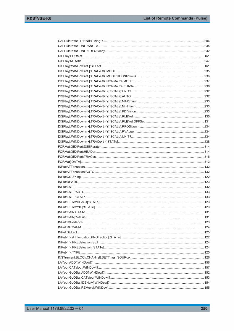
List of Remote Commands (Pulse)R&S®VSE-K6
350User Manual 1176.8922.02 ─ 04
CALCulate<n>:TRENd:TIMing:Y................................................................................................................... 206CALCulate<n>:UNIT:ANGLe......................................................................................................................... 235CALCulate<n>:UNIT:FREQuency................................................................................................................. 232DISPlay:FORMat........................................................................................................................................... 161DISPlay:MTABle............................................................................................................................................ 247DISPlay[:WINDow<n>]:SELect......................................................................................................................161DISPlay[:WINDow<n>]:TRACe<t>:MODE.....................................................................................................235DISPlay[:WINDow<n>]:TRACe<t>:MODE:HCONtinuous..............................................................................236DISPlay[:WINDow<n>]:TRACe<t>:NORMalize:MODE................................................................................. 237DISPlay[:WINDow<n>]:TRACe<t>:NORMalize:PHASe................................................................................ 238DISPlay[:WINDow<n>]:TRACe<t>:X[:SCALe]:UNIT?................................................................................... 232DISPlay[:WINDow<n>]:TRACe<t>:Y[:SCALe]:AUTO....................................................................................232DISPlay[:WINDow<n>]:TRACe<t>:Y[:SCALe]:MAXimum............................................................................. 233DISPlay[:WINDow<n>]:TRACe<t>:Y[:SCALe]:MINimum.............................................................................. 233DISPlay[:WINDow<n>]:TRACe<t>:Y[:SCALe]:PDIVision..............................................................................233DISPlay[:WINDow<n>]:TRACe<t>:Y[:SCALe]:RLEVel..................................................................................130DISPlay[:WINDow<n>]:TRACe<t>:Y[:SCALe]:RLEVel:OFFSet....................................................................131DISPlay[:WINDow<n>]:TRACe<t>:Y[:SCALe]:RPOSition.............................................................................234DISPlay[:WINDow<n>]:TRACe<t>:Y[:SCALe]:RVALue................................................................................ 234DISPlay[:WINDow<n>]:TRACe<t>:Y[:SCALe]:UNIT?................................................................................... 234DISPlay[:WINDow<n>]:TRACe<t>[:STATe].................................................................................................. 238FORMat:DEXPort:DSEParator...................................................................................................................... 314FORMat:DEXPort:HEADer............................................................................................................................ 314FORMat:DEXPort:TRACes............................................................................................................................315FORMat[:DATA].............................................................................................................................................313INPut:ATTenuation........................................................................................................................................ 132INPut:ATTenuation:AUTO............................................................................................................................. 132INPut:COUPling.............................................................................................................................................122INPut:DPATh................................................................................................................................................. 123INPut:EATT....................................................................................................................................................132INPut:EATT:AUTO.........................................................................................................................................133INPut:EATT:STATe........................................................................................................................................133INPut:FILTer:HPASs[:STATe]........................................................................................................................123INPut:FILTer:YIG[:STATe].............................................................................................................................123INPut:GAIN:STATe........................................................................................................................................131INPut:GAIN[:VALue]...................................................................................................................................... 131INPut:IMPedance...........................................................................................................................................123INPut:RF:CAPM.............................................................................................................................................124INPut:SELect................................................................................................................................................. 125INPut<n>:ATTenuation:PROTection[:STATe]............................................................................................... 122INPut<n>:PRESelection:SET.........................................................................................................................124INPut<n>:PRESelection[:STATe].................................................................................................................. 124INPut<n>:TYPE............................................................................................................................................. 125INSTrument:BLOCk:CHANnel[:SETTings]:SOURce.....................................................................................126LAYout:ADD[:WINDow]?............................................................................................................................... 156LAYout:CATalog[:WINDow]?.........................................................................................................................157LAYout:GLOBal:ADD[:WINDow]?..................................................................................................................152LAYout:GLOBal:CATalog[:WINDow]?........................................................................................................... 153LAYout:GLOBal:IDENtify[:WINDow]?............................................................................................................154LAYout:GLOBal:REMove[:WINDow]............................................................................................................. 155

List of Remote Commands (Pulse)R&S®VSE-K6
351User Manual 1176.8922.02 ─ 04
LAYout:GLOBal:REPLace[:WINDow]............................................................................................................155LAYout:IDENtify[:WINDow]?..........................................................................................................................158LAYout:REMove[:WINDow]........................................................................................................................... 158LAYout:REPLace[:WINDow]..........................................................................................................................159LAYout:WINDow<n>:ADD?........................................................................................................................... 159LAYout:WINDow<n>:IDENtify?......................................................................................................................160LAYout:WINDow<n>:REMove.......................................................................................................................160LAYout:WINDow<n>:REPLace......................................................................................................................161MMEMory:STORe<n>:TABLe....................................................................................................................... 315MMEMory:STORe<n>:TABLe:LIMit...............................................................................................................316MMEMory:STORe<n>:TRACe.......................................................................................................................256OUTPut:TRIGger<port>:DIRection................................................................................................................140OUTPut:TRIGger<port>:LEVel...................................................................................................................... 140OUTPut:TRIGger<port>:OTYPe....................................................................................................................141OUTPut:TRIGger<port>:PULSe:IMMediate...................................................................................................141OUTPut:TRIGger<port>:PULSe:LENGth.......................................................................................................141SENSe:TRACe:MEASurement:ALGorithm....................................................................................................146SENSe:TRACe:MEASurement:DEFine:AMPLitude:UNIT.............................................................................146SENSe:TRACe:MEASurement:DEFine:BOUNdary:TOP.............................................................................. 146SENSe:TRACe:MEASurement:DEFine:COMPensate:ADRoop....................................................................147SENSe:TRACe:MEASurement:DEFine:DURation:AUTO............................................................................. 119SENSe:TRACe:MEASurement:DEFine:DURation:MAX................................................................................119SENSe:TRACe:MEASurement:DEFine:DURation:MIN.................................................................................119SENSe:TRACe:MEASurement:DEFine:DURation:OFF................................................................................ 119SENSe:TRACe:MEASurement:DEFine:FREQuency:OFFSet.......................................................................120SENSe:TRACe:MEASurement:DEFine:FREQuency:OFFSet:AUTO............................................................120SENSe:TRACe:MEASurement:DEFine:FREQuency:RATE..........................................................................120SENSe:TRACe:MEASurement:DEFine:FREQuency:RATE:AUTO...............................................................120SENSe:TRACe:MEASurement:DEFine:PULSe:ADRoop..............................................................................120SENSe:TRACe:MEASurement:DEFine:PULSe:ESTimation:LENGth........................................................... 150SENSe:TRACe:MEASurement:DEFine:PULSe:ESTimation:OFFSet:LEFT..................................................151SENSe:TRACe:MEASurement:DEFine:PULSe:ESTimation:OFFSet:RIGHt................................................ 151SENSe:TRACe:MEASurement:DEFine:PULSe:ESTimation:REFerence......................................................151SENSe:TRACe:MEASurement:DEFine:PULSe:INSTant.............................................................................. 148SENSe:TRACe:MEASurement:DEFine:PULSe:INSTant:AWINdow............................................................. 148SENSe:TRACe:MEASurement:DEFine:PULSe:INSTant:REFerence........................................................... 149SENSe:TRACe:MEASurement:DEFine:PULSe:MODulation.........................................................................121SENSe:TRACe:MEASurement:DEFine:PULSe:PERiod............................................................................... 121SENSe:TRACe:MEASurement:DEFine:PULSe:REFerence......................................................................... 149SENSe:TRACe:MEASurement:DEFine:PULSe:REFerence:POSition.......................................................... 149SENSe:TRACe:MEASurement:DEFine:PULSe:SELected............................................................................162SENSe:TRACe:MEASurement:DEFine:RIPPle.............................................................................................147SENSe:TRACe:MEASurement:DEFine:RRANge:ALIGnment.......................................................................163SENSe:TRACe:MEASurement:DEFine:RRANge:AUTO...............................................................................163SENSe:TRACe:MEASurement:DEFine:RRANge:LENGth............................................................................163SENSe:TRACe:MEASurement:DEFine:RRANge:OFFSet............................................................................ 164SENSe:TRACe:MEASurement:DEFine:RRANge:REFerence.......................................................................164SENSe:TRACe:MEASurement:DEFine:TRANsition:HREFerence................................................................147SENSe:TRACe:MEASurement:DEFine:TRANsition:LREFerence.................................................................147SENSe:TRACe:MEASurement:DEFine:TRANsition:REFerence...................................................................148

List of Remote Commands (Pulse)R&S®VSE-K6
352User Manual 1176.8922.02 ─ 04
SENSe:TRACe:MEASurement:POWer:AVG?...............................................................................................310SENSe:TRACe:MEASurement:POWer:MAX?.............................................................................................. 310SENSe:TRACe:MEASurement:POWer:MIN?................................................................................................310SENSe:TRACe:MEASurement:POWer:PULSe:BASE?................................................................................ 310SENSe:TRACe:MEASurement:POWer:PULSe:TOP?.................................................................................. 310SENSe:TRACe:MEASurement:PULSe:DCYCle?..........................................................................................310SENSe:TRACe:MEASurement:PULSe:DURation?.......................................................................................310SENSe:TRACe:MEASurement:PULSe:PERiod?.......................................................................................... 311SENSe:TRACe:MEASurement:PULSe:SEParation?.................................................................................... 311SENSe:TRACe:MEASurement:TRANsition:NEGative:DURation?................................................................311SENSe:TRACe:MEASurement:TRANsition:POSitive:DURation?................................................................. 311SENSe:TRACe:MEASurement:TRANsition:POSitive:OVERshoot:MAXimum?............................................ 311SENSe:TRACe:MEASurement:TRANsition:POSitive:OVERshoot?..............................................................311SYSTem:COMMunicate:RDEVice:OSCilloscope:PSMode[:STATe]............................................................. 127SYSTem:COMMunicate:RDEVice:OSCilloscope:SRATe..............................................................................127SYSTem:COMMunicate:RDEVice:OSCilloscope:TCPip............................................................................... 126SYSTem:COMMunicate:RDEVice:OSCilloscope:VDEVice?.........................................................................127SYSTem:COMMunicate:RDEVice:OSCilloscope:VFIRmware?.................................................................... 128SYSTem:COMMunicate:RDEVice:OSCilloscope[:STATe]............................................................................126SYSTem:PRESet:CHANnel[:EXEC]..............................................................................................................118TRACe:IQ:DATA:MEMory?........................................................................................................................... 254TRACe:IQ:DATA:RRANge?...........................................................................................................................255TRACe:IQ:DATA?..........................................................................................................................................254TRACe<n>[:DATA]:X?...................................................................................................................................253TRACe<n>[:DATA]?...................................................................................................................................... 253TRIGger[:SEQuence]:DTIMe.........................................................................................................................134TRIGger[:SEQuence]:HOLDoff[:TIME].......................................................................................................... 134TRIGger[:SEQuence]:IFPower:HOLDoff....................................................................................................... 135TRIGger[:SEQuence]:IFPower:HYSTeresis.................................................................................................. 135TRIGger[:SEQuence]:LEVel:IFPower............................................................................................................136TRIGger[:SEQuence]:LEVel:IQPower........................................................................................................... 136TRIGger[:SEQuence]:LEVel:MAPower..........................................................................................................136TRIGger[:SEQuence]:LEVel:RFPower.......................................................................................................... 137TRIGger[:SEQuence]:LEVel[:EXTernal<port>]..............................................................................................135TRIGger[:SEQuence]:MAPower:HOLDoff..................................................................................................... 136TRIGger[:SEQuence]:MAPower:HYSTeresis................................................................................................137TRIGger[:SEQuence]:RFPower:HOLDoff......................................................................................................137TRIGger[:SEQuence]:SLOPe........................................................................................................................ 138TRIGger[:SEQuence]:SOURce......................................................................................................................138TRIGger[:SEQuence]:TIME:RINTerval..........................................................................................................140UNIT:ANGLe..................................................................................................................................................235

IndexR&S®VSE-K6
353User Manual 1176.8922.02 ─ 04
Index
A
AC/DC coupling .................................................................56Activating
Pulse measurements (remote) ................................. 117Algorithm
Base/Top level ............................................................ 73Alignment
Result range ............................................................... 80Amplitude .................................................. 16, 219, 220, 261
Configuration (remote) .............................................. 130Configuration (Softkey) ............................................... 62Settings ....................................................................... 62
AnalysisRemote control ......................................................... 235
ASCII trace export ........................................................... 334Attenuation ........................................................................ 63
Auto ............................................................................ 63Configuration (remote) .............................................. 132Electronic .................................................................... 64Manual ........................................................................ 63Option ......................................................................... 64
Auto scaling .......................................................................94Auto settings ..................................................................... 77Average count ................................................................. 106Averaging window
Measurement point ..................................................... 75
B
B2000State ........................................................................... 57
Base level ..........................................................................39Algorithm .....................................................................73
Base power ....................................................... 15, 220, 264Boundary ........................................................................... 74
C
CaptureTime (remote) ........................................................... 143
"Capture Count" ............................................................. 106Capture mode
Remote ..................................................................... 124Cardinal data points
Parameters ................................................................. 21Center frequency ...............................................................61
Step size ..................................................................... 61Chirp rate .................................................. 20, 215, 285, 286
Auto mode .................................................................. 54Configuring ................................................................. 54
ClosingWindows (remote) .....................................155, 158, 160
ConfigurationMeasurement (remote) ............................................. 118
ConventionsSCPI commands ....................................................... 113
CouplingInput (remote) ........................................................... 122
D
Data acquisitionBandwidth ................................................................... 69Filter type .................................................................... 69Measurement time ...................................................... 69Remote control ......................................................... 142Softkey ........................................................................ 68
Data formatRemote ..................................................... 313, 314, 315
Decimal separatorTrace export ........................................................90, 108
Delta markers .................................................................... 98Defining .......................................................................98
DetectorsRemote control ......................................................... 239Trace .........................................................................105
Diagram footer information ................................................10Direct path
Input configuration ...................................................... 56Remote ..................................................................... 123
DistalThreshold .................................................................... 73
Droop ................................................................ 40, 218, 219Calculation .................................................................. 37Considering .................................................................72Ratio ........................................................... 17, 259, 260
Drop-out timeTrigger ........................................................................ 67
Duty cycle ..........................................................14, 224, 276Duty ratio ........................................................... 14, 225, 277
E
Electronic input attenuation ......................................... 63, 64Envelope model
Parameters ................................................................. 21Errors
IF OVLD ...................................................................... 63Evaluation
Magnitude Capture ..................................................... 25Parameter Distribution ................................................ 27Parameter Spectrum ...................................................27Parameter Trend .........................................................28Pulse Frequency ......................................................... 30Pulse Magnitude ......................................................... 30Pulse Phase ................................................................31Pulse phase (wrapped) ............................................... 32Pulse Results .............................................................. 32Pulse Statistics ........................................................... 34Result Range Spectrum ..............................................35
Evaluation methodsRemote ............................................................. 152, 156
Evaluation rangesee Measurement range ............................................. 76
Evaluations ........................................................................25Export format
Traces ....................................................................... 334Exporting
I/Q data ..................................................................... 107Measurement settings .............................................. 108Table results ............................................................... 89Traces ....................................................................... 107

IndexR&S®VSE-K6
354User Manual 1176.8922.02 ─ 04
External trigger .................................................................. 66Level (remote) ...........................................................135
F
"Fall Base Point Time" ...................................................... 23"Fall High Point Level" .......................................................25"Fall High Point Time" ....................................................... 24"Fall Low Point Level" ....................................................... 24"Fall Low Point Time" ........................................................ 24"Fall Mid Point Level" ........................................................ 24"Fall Mid Point Time" ......................................................... 24Fall time .......................................................13, 40, 225, 278
Position ....................................................................... 72Thresholds .................................................................. 71
"Fall Top Point Level" ........................................................ 25"Fall Top Point Time" ........................................................ 24File format
Trace export ..............................................................334Filter type
Data acquisition .......................................................... 69Gauss, effects ........................................................... 336
FiltersHigh-pass (remote) ................................................... 123High-pass (RF input) ...................................................56YIG (remote) ............................................................. 123
FM video bandwidth .......................................................... 82Format
Data (remote) ............................................313, 314, 315Free Run
Trigger ........................................................................ 65Frequency ................................................................. 19, 216
Configuration (remote) .............................................. 128Configuration (Softkey) ............................................... 61Deviation ............................................................. 19, 215Difference between pulses ................................. 19, 216Error (Peak) ................................................ 19, 216, 286Error (RMS) ........................................ 19, 217, 288, 289Offset .......................................................................... 62
Frequency offsetAuto mode .................................................................. 54Value ...........................................................................54
FrontendConfiguration .............................................................. 60Configuration (remote) .............................................. 128
G
Gauss filtersLarge Bandwidth ....................................................... 336
H
Hardware settingsDisplayed ...................................................................... 9
HighThreshold .................................................................... 73
High-pass filterRemote ..................................................................... 123RF input ...................................................................... 56
Histogram binsParameter Distribution ................................................ 84
HoldTrace setting ............................................................. 105
HysteresisPulse detection ........................................................... 71Trigger ........................................................................ 68
I
I/Q dataExporting ...................................................................107
I/Q PowerTrigger ........................................................................ 66Trigger level (remote) ............................................... 136
IF PowerTrigger ........................................................................ 66Trigger level (remote) ............................................... 136
ImpedanceRemote ..................................................................... 123Setting .........................................................................59
Input .................................................................................. 59B2000 ......................................................................... 57Coupling ......................................................................56Coupling (remote) ..................................................... 122Settings ....................................................................... 64
Input sourcesChannels ...............................................................56, 60Instrument ................................................................... 56Radio frequency (RF) ................................................. 55
InstrumentsInput source ................................................................ 56
K
KeysMKR -> ......................................................................102
L
LengthResult range ............................................................... 80
Levels100% .....................................................................39, 72Base ............................................................................39Median ........................................................................ 39OFF .............................................................................39ON .............................................................................. 39Top ..............................................................................39
Limit checksPulse Results .............................................................. 32
LimitsDetection .....................................................................71Parameters ................................................................. 92
LinkingMarkers ....................................................................... 99
LO feedthrough ................................................................. 56Low
Threshold .................................................................... 73
M
Magnitude CaptureEvaluation ................................................................... 25
Marker tableConfiguring ............................................................... 100Evaluation method ...................................................... 26
Marker to Trace ................................................................. 99Markers
Assigned trace ............................................................ 99Configuration (softkey) ................................................95Configuring ................................................................. 96Deactivating .............................................................. 100Delta markers ............................................................. 98General settings (remote) ......................................... 246

IndexR&S®VSE-K6
355User Manual 1176.8922.02 ─ 04
Linking ........................................................................ 99Linking across windows ............................................ 100Linking to pulse ......................................................... 101Minimum ................................................................... 103Minimum (remote control) ......................................... 247Next minimum ........................................................... 103Next minimum (remote control) ................................ 247Next peak ..................................................................103Next peak (remote control) ....................................... 247Peak ..........................................................................103Peak (remote control) ............................................... 247Positioning ................................................................ 102Querying position (remote) ....................................... 318Selecting ..................................................................... 97Settings (remote) ...................................................... 241State ........................................................................... 98Table ......................................................................... 100Table (evaluation method) .......................................... 26Type ...................................................................... 97, 98
Measurement bandwidthData acquisition .......................................................... 69
Measurement channelsInput source .......................................................... 56, 60
Measurement levelsConfiguring ................................................................. 71Configuring (remote) ................................................. 146
Measurement pointConfiguring ................................................................. 74Configuring (remote) ................................................. 148Reference ................................................................... 74
Measurement range .......................................................... 11Configuring ................................................................. 76Configuring (remote) ................................................. 150
Measurement time ............................................................ 69Remote ..................................................................... 143
MesialThreshold .................................................................... 73
MidThreshold .................................................................... 73
Mid level ............................................................................ 39Minimum ..........................................................................103
Marker positioning .................................................... 103Next .......................................................................... 103
Minimum attenuation ......................................................... 59MKR ->
Key ............................................................................102
N
Next Minimum ................................................................. 103Marker positioning .................................................... 103
Next Peak ........................................................................103Marker positioning .................................................... 103
NormalizationPhases ........................................................................ 95Referenced pulse ........................................................75Trace .........................................................................106
O
OFFLevel ........................................................................... 39
Off time ..............................................................14, 278, 279OFF time ................................................................... 40, 225Offset
Frequency ................................................................... 62Measurement point ..................................................... 75
Reference level ........................................................... 63Result range ............................................................... 80
ONLevel ........................................................................... 39
ON powerAverage .............................................. 16, 221, 266, 267Peak-to-Avg ratio ........................................ 17, 223, 271
ON time ............................................................... 14, 40, 281Options
Electronic attenuation ................................................. 64High-pass filter .................................................... 56, 123Preamplifier .................................................................64
OscilloscopeAddress .......................................................................58
Overshoot ................................................................221, 222Calculation .................................................................. 39Ratio ........................................................... 18, 267, 268
Overview ........................................................................... 50
P
ParameterConfiguration (result displays) .................................... 82
Parameter distributionConfiguration (remote) .............................................. 164
Parameter DistributionBins ............................................................................. 84Configuration .............................................................. 82Evaluation ................................................................... 27Parameters ................................................................. 83X-axis .......................................................................... 83Y-axis .......................................................................... 84
Parameter spectrumConfiguration (remote) .............................................. 171
Parameter SpectrumConfiguration .............................................................. 84Evaluation ................................................................... 27Parameters ................................................................. 85X-axis .......................................................................... 86
Parameter tablesConfiguration .............................................................. 88Configuration (remote) .............................................. 208
Parameter trendConfiguration .............................................................. 87Configuration (remote) .............................................. 178Evaluation ................................................................... 28Parameters ................................................................. 88X-axis .......................................................................... 88Y-axis .......................................................................... 88
Parameters ........................................................................14Amplitude .................................................................... 15Avg ON Power ............................................................ 16Avg Tx Power ............................................................. 16Base Power ................................................................ 15Chirp Rate ...................................................................20Description .................................................................. 11Droop .......................................................................... 17Duty Cycle (%) ............................................................ 14Envelope model ........................................ 22, 23, 24, 25Fall Time ..................................................................... 13Frequency ............................................................. 18, 19Frequency Deviation ................................................... 19Frequency Error (Peak) .............................................. 19Frequency Error (RMS) .............................................. 19IEEE 181 Standard ..................................................... 11Min Power ................................................................... 16Off Time ...................................................................... 14

IndexR&S®VSE-K6
356User Manual 1176.8922.02 ─ 04
ON Time ..................................................................... 14Overshoot ................................................................... 18Peak Power ................................................................ 16Peak-to-Average Tx Power Ratio ............................... 17Peak-to-Avg ON Power Ratio ..................................... 17Peak-to-Min Power Ratio ............................................ 17Phase ..........................................................................20Phase Deviation ..........................................................21Phase Error (Peak) ..................................................... 21Phase Error (RMS) ..................................................... 20Power ....................................................................15, 18Pulse Amplitude .......................................................... 16Pulse Period ............................................................... 14Pulse Repetition Frequency (Hz) ................................ 15Pulse Repetition Interval ............................................. 14Pulse Width .................................................................14Pulse-Pulse Frequency Difference ............................. 19Pulse-Pulse Phase Difference .................................... 20Pulse-to-Pulse Power Ratio ........................................ 18Ripple ..........................................................................17Rise Time ....................................................................13Settling Time ............................................................... 13Timestamp .................................................................. 13Top Power .................................................................. 15
Peak excursion ................................................................102Peak frequency error .......................................................216Peak search
Mode ......................................................................... 101Peaks
Marker positioning .................................................... 103Next .......................................................................... 103
PerformingPulse measurement .................................................. 109
Phase ................................................................................ 20Deviation ............................................................. 21, 290Difference between pulses ................................. 20, 293Error (Peak) ........................................................ 21, 291Error (RMS) ........................................................ 20, 293Unwrapped (evaluation) ..............................................31Wrapped (evaluation) ................................................. 32
Phase deviation ...............................................................217Phase Error (Peak) ......................................................... 217Phase Error (RMS) ..........................................................218Phases
Normalization .............................................................. 95Position
100% level .................................................................. 72Power
at point ........................................................................ 18Average ON ........................................ 16, 221, 266, 267Average transmission ................................. 16, 263, 264Base ............................................................15, 220, 264Minimum transmission ........................ 16, 221, 265, 266Peak to average ratio transmission ............ 17, 222, 269Peak to min ratio transmission ............17, 222, 269, 270Peak transmission ...................................... 16, 221, 265Peak-to-Avg ratio ON ..................................17, 223, 271Range ................................................. 16, 219, 220, 261Top ..............................................................15, 224, 274
Power splitter mode .................................................. 58, 127Preamplifier
Setting .........................................................................64Preselector ........................................................................ 58Presetting
Channels .....................................................................52Pretrigger .......................................................................... 67
ProximalThreshold .................................................................... 73
PulseDroop .......................................................................... 53Frequency (evaluation) ............................................... 30Magnitude (evaluation) ............................................... 30Modulation .................................................................. 53Negative ......................................................................39Off time ....................................................................... 54Period ............................................................. 14, 40, 53Phase (evaluation) ...................................................... 31Phase, wrapped (evaluation) ...................................... 32Positive ....................................................................... 39Repetition interval ....................................................... 40Selecting ..................................................................... 78Selecting (remote) .................................................... 162Statistics (evaluation) ..................................................34Width ...............................................14, 40, 54, 226, 281
Pulse detectionBasics ......................................................................... 39Configuring ................................................................. 70Limit ............................................................................ 71Maximum count .......................................................... 71Remote control ......................................................... 144
Pulse measurementsBasics ......................................................................... 36
Pulse repetition frequency .........................15, 225, 279, 280Pulse repetition interval ................................................... 226Pulse Results
Evaluation ................................................................... 32Pulse-Pulse Frequency Difference ..........................216, 288Pulse-Pulse Phase Difference ................................ 218, 292Pulse-to-Pulse Power Difference ............................ 223, 272Pulse-to-Pulse Power Ratio .............................................. 18
Q
Quick ConfigTraces ....................................................................... 107
R
RangeScaling ........................................................................ 94
Range power ............................................. 16, 219, 220, 261Record length .................................................................... 70Reference
Measurement point ..................................................... 74Measurement range ....................................................76Normalization .............................................................. 75Pulse ........................................................................... 75Pulse detection ........................................................... 70Result range ............................................................... 80
Reference level ................................................................. 63Offset .......................................................................... 63Unit ....................................................................... 63, 73Value ...........................................................................63
Reference marker ............................................................. 98Remote commands
Basics on syntax ....................................................... 112Boolean values ......................................................... 116Capitalization ............................................................ 114Character data .......................................................... 116Data blocks ............................................................... 117Numeric values ......................................................... 115Optional keywords .................................................... 114Parameters ............................................................... 115

IndexR&S®VSE-K6
357User Manual 1176.8922.02 ─ 04
Strings .......................................................................117Suffixes ..................................................................... 114
Repetition interval ..................................................... 14, 280Restoring
Channel settings ......................................................... 52Result configuration
Remote control ......................................................... 162Softkey ........................................................................ 78
Result displays .................................................................. 25Marker table ................................................................ 26
Result range ...................................................................... 11Alignment .................................................................... 80Configuring ................................................................. 79Configuring (remote) ................................................. 162Length ......................................................................... 80Reference ................................................................... 80Spectrum .................................................................... 80
Result Range SpectrumEvaluation ................................................................... 35
ResultsData format (remote) ................................ 313, 314, 315Exporting ...................................................................108
RF attenuationAuto ............................................................................ 63Manual ........................................................................ 63
RF input .......................................................................55, 59Remote ............................................................. 122, 125
RF PowerTrigger ........................................................................ 66Trigger level (remote) ............................................... 137
Ripple ................................................................ 73, 223, 224Calculation .................................................................. 37Ratio ........................................................... 17, 273, 274
"Rise Base Point Time" ..................................................... 22"Rise High Point Level" ..................................................... 23"Rise High Point Time" ...................................................... 23"Rise Low Point Level" ...................................................... 23"Rise Low Point Time" .......................................................22"Rise Mid Point Level" ....................................................... 23"Rise Mid Point Time" ....................................................... 22Rise time ............................................. 13, 40, 226, 281, 282
Position ....................................................................... 72Thresholds .................................................................. 71
"Rise Top Point Level" ...................................................... 23"Rise Top Point Time" ....................................................... 23RMS frequency error ....................................................... 217
S
Sample rate ....................................................................... 69Scaling
Amplitude range, automatically ...................................94Automatic .................................................................... 93Y-axis .................................................................... 92, 93Y-axis (remote) ......................................................... 231
SearchingConfiguration ............................................................ 101
Select Marker ............................................................ 99, 102Selected Pulse
Softkey ........................................................................ 78Settling time ........................................ 13, 74, 226, 282, 283Signal description
Configuration .............................................................. 52Configuration (remote) .............................................. 118Softkey ........................................................................ 52
Signal sourceRemote ..................................................................... 125
SlopeTrigger ................................................................ 67, 138
SoftkeysAmplitude Config ........................................................ 62Data acquisition .......................................................... 68Frequency Config ....................................................... 61Marker 1, Marker 2 …16 ............................................. 97Marker Config ............................................................. 95Marker Type ................................................................97Result Config .............................................................. 78Selected Pulse ............................................................ 78Signal Description ....................................................... 52Trace Config ............................................................. 103Trigger/Gate Config .................................................... 64
Specifics forConfiguration .............................................................. 52
SpectrumResult range ............................................................... 80
StatisticsConfiguration .............................................................. 88Configuration (remote) .............................................. 208
SuffixesCommon ................................................................... 117Remote commands ...................................................114
T
TablesExporting ...............................................................89, 90
ThresholdsConfiguring (remote) ................................................. 146Fall time ...................................................................... 71High (Distal) ................................................................ 73Low (Proximal) ............................................................ 73Mid (Mesial) ................................................................ 73Pulse detection ..................................................... 39, 71Reference ................................................................... 70Rise time ..................................................................... 71
Timestamp ................................................................ 13, 283Timestamps .....................................................................227Timing
Auto mode .................................................................. 53Toolbars
AutoSet ..................................................................... 333Control ...................................................................... 331Functions .................................................................. 330Help .......................................................................... 331Main .......................................................................... 330Marker .......................................................................332Overview ................................................................... 330Zoom .........................................................................331
Top level ............................................................................39Algorithm .....................................................................73
Top power ......................................................... 15, 224, 274Traces ............................................................................. 107
Configuration (softkey) ..............................................103Configuring (remote control) ..................................... 235Detector .................................................................... 105Detector (remote control) .......................................... 239Export format ...................................................... 90, 108Exporting ...........................................................107, 108Hold .......................................................................... 105Mode ......................................................................... 105Mode (remote) .......................................................... 235Selecting ................................................................... 104Settings ....................................................................... 45

IndexR&S®VSE-K6
358User Manual 1176.8922.02 ─ 04
Settings (remote control) .......................................... 235Settings, predefined .................................................. 107
Transmission powerAverage .............................................. 16, 220, 263, 264Minimum ............................................. 16, 221, 265, 266Peak ............................................................16, 221, 265Peak to average ratio ..................................17, 222, 269Peak to min ratio ................................. 17, 222, 269, 270
TriggerConditions (remote) .................................................. 134Drop-out time .............................................................. 67External (remote) ...................................................... 138Holdoff ........................................................................ 68Hysteresis ................................................................... 68Offset .......................................................................... 67Remote control ......................................................... 133Slope ...................................................................67, 138
Trigger level ...................................................................... 67External trigger (remote) ........................................... 135I/Q Power (remote) ................................................... 136IF Power (remote) ..................................................... 136RF Power (remote) ................................................... 137
Trigger source ................................................................... 65External .......................................................................66Free Run ..................................................................... 65I/Q Power .................................................................... 66IF Power ..................................................................... 66RF Power .................................................................... 66
Trigger/GateConfiguration (Softkey) ............................................... 64
TX powersee Transmission power ..................... 16, 220, 263, 264
U
UnitsReference level ..................................................... 63, 73
W
Window title bar information ................................................ 9Windows
Adding (remote) ................................................ 152, 156Closing (remote) ....................................... 155, 158, 160Configuring ................................................................. 52Querying (remote) .............................153, 154, 157, 158Replacing (remote) ........................................... 155, 159Types (remote) ................................................. 152, 156
X
X-axisParameter Distribution ................................................ 83Parameter Spectrum ...................................................86Parameter trend .......................................................... 88
X-valueMarker .........................................................................98
Y
Y-axisParameter Distribution ................................................ 84Parameter trend .......................................................... 88Scaling ........................................................................ 93
Y-Scaling ........................................................................... 92Remote control ......................................................... 231
YIG-preselectorActivating/Deactivating ............................................... 57Activating/Deactivating (remote) ............................... 123