rtr-5w vld for windows vld-5weu -...
TRANSCRIPT
2010.10 16510010001 3rd Edition
User's ManualThank you for purchasing our product.
Carefully read this instruction manual before
using this unit.
RTR-5W VLD for WindowsVLD-5WEU
© Copyright T&D Corporation. All rights reserved.

Notices about this User's Manual
In order to properly use this product, please carefully read this manual before using.
- All rights of this User's Manual belong to T&D Corporation. It is prohibited to use, duplicate and/or arrange a part or whole of this User's Manual without the permission of T&D Corporation.
- Microsoft and Windows are registered trademarks of Microsoft Corpora-tion in the United States and/or other countries.
- Windows Vista is either a registered trademark or trademark of Microsoft Corporation in the United States and/or other countries.
- Company names and product names are trademarks or registered trademarks of each company.
- Specifications, design and other contents outlined in this manual are subject to change without notice.
- On screen messages in this manual may vary slightly from the actual messages.
- Please notify the shop where you purchased this product or T&D Corporation of any mistakes, errors or unclear explanations in this manual. T&D Corporation accepts no responsibility for any damage or loss of income caused by the use of our product.
- This software has been designed for private or industrial use only. It is not for use in situations where strict safety precautions are necessary, whether directly or indirectly.
- Some of our products, which come under the category of strategic goods in foreign trade law, need the permission of the Japanese government to be exported outside of Japan.
- Please read the warranty and provisions for free repair carefully.

1
T&D CORPORATION SOFTWARE LICENSE AGREEMENT
RTR-5W VLD for WindowsBefore removing the master disc from its package, you must agree with all parts of this End-User License Agreement (as defined below). This End-User License Agreement (hereafter, referred to as "the agreement") is a binding legal agreement for the use of T&D Corporation Software products (hereafter, referred as "the SOFTWARE PRODUCT") between you, (hereafter referred to as "the USER"), and T&D Corporation (hereafter referred to as "T&D"). The SOFTWARE PRODUCT includes computer software, the associated media and any printed materials. The SOFTWARE PRODUCT also includes any and all updates to the SOFTWARE PRODUCT and additional functions, which T&D may offer the USER in the future. By installing, copying, downloading, accessing, or otherwise using the SOFTWARE PRODUCT, the USER agrees to be bound by the terms of the agreement. If the USER does not agree to the terms of the agreement, the USER should promptly return the SOFTWARE PRODUCT to the store where the SOFTWARE PRODUCT was bought or directly to T&D. In such an event, costs incurred for the return will be the sole responsibility of the USER.
1. Granting of License1-1. The SOFTWARE PRODUCT may be installed and used on only one computer.
If the USER changes computers for some reason, all of the SOFTWARE PRODUCT used on the previous computer must be destroyed.
1-2. The User is granted permission to make only one copy of the SOFTWARE PRODUCT for the purpose of recovery due to loss or damage. However, the SOFTWARE PRODUCT may not be copied for use on a different computer, nor for the purpose of renting and leasing.
1-3. All titles and copyrights to the SOFTWARE PRODUCT are owned solely by T&D.
2. Start and Termination of License2-1. The terms stipulated in the agreement come into effect upon the removal of the
master disc from its package. 2-2. When the USER finishes using the SOFTWARE PRODUCT and has destroyed
it, the agreement will be regarded as having been terminated. 2-3. Even though the USER may have not finished using the SOFTWARE
PRODUCT, if the USER is deemed to be in violation with any terms written in the agreement, T&D may terminate the agreement and cancel the USER'S rights to use of the SOFTWARE PRODUCT. In such an event, the USER must promptly destroy the SOFTWARE PRODUCT without delay.
2
3. Rights and Limitations3-1. Limitations of Reverse Engineering, Decompilation and Disassembly.
The User may not reverse engineer, decompile, or disassemble the SOFTWARE PRODUCT.
3-2. Licensed Areas The USER is granted permission to use the SOFTWARE PRODUCT solely in the United States, Canada and areas where the product can be used legally according to the wireless radio regulations for that country. T&D does not in any manner whatsoever guarantee the use of the SOFTWARE PRODUCT in any areas other than stated above.
3-3. Prohibition of Transferring Rights The USER may not transfer any part of the SOFTWARE PRODUCT after opening the master disc to a third party or share it with anyone by dividing it.
3-4. Updates By registering with T&D as a customer using the SOFTWARE PRODUCT, the USER obtains the right to be offered updates and additional functions as they are developed and dispersed in the future. Note, however, that in some cases the procurement of these updates and additional functions may come at an additional cost to be paid by the USER.
4. Quality Assurance 4-1. If the SOFTWARE PRODUCT does not work due to causes resulting from the
product itself or material defects, T&D offers the USER free exchange of the product for the period of one year from the time of purchase. Note however, the USER will need to register with T&D as a SOFTWARE PRODUCT customer in order to have the product exchanged.
4-2. If the situation stated above occurs due to factors which are not the responsibility of T&D nor due to defect in the SOFTWARE PRODUCT, including fire, earthquake, and any other natural disaster, acts by a third party, any erroneous operation carried out by the USER, whether that action be intentional or by mistake, this includes the use of the product in any manner other than defined as acceptable in the User's Manual, T&D shall not offer free exchange of the product.
5. Limitation of Guarantee 5-1. T&D shall not accept any responsibility for any damage, whether direct or
indirect, that results from the usage of SOFTWARE PRODUCT. T&D shall not accept any responsibility for any damage, whether direct or indirect, that results from defects in the SOFTWARE PRODUCT.
5-2. Neither T&D sales representatives nor employees have any authorization to reinterpret, add, subtract or make changes in any manner whatsoever to the contents of the agreement. Accordingly, T&D shall not be held liable for any oral or written information or notice which such sales representatives or employees may offer the USER other than those explicitly stated in the agreement.

3
6. Others Any conflicts relating to the agreement shall be handled through the jurisdiction of the Matsumoto Branch of the Nagano District Court. <Regarding Returns>1. Products which have been even used just once after purchase cannot be accepted
for return. 2. In the following situations, returns cannot be accepted:
- When the damage or malfunction was the result of improper usage by the USER and hence was cause by the USER.
- When the time period for accepting returns has expired and no notice comes from the USER concerning a return.
3. The time period for accepting returns is two weeks from the date of purchase.
Copyright1. All copyrights RTR-5W VLD for Windows, including all of the programs
and all related documents, are the sole property of T&D Corporation.2. The reprinting or redistribution for commercial purposes whether in part
or in whole, in magazines or as a part of any product is strictly forbidden without the expressed consent of T&D Corporation. Any inquires concerning commercial redistribution should be directed to the Sales Department of T&D Corporation.
3. Please do not attempt to make any changes or modifications to RTR-5W VLD for Windows.

4
Contents
Notices about this User's Manual ----------- iiT&D CORPORATION SOFTWARE LICENSE AGREEMENT ----1
Copyright -------------------------------------------------- 3
What is RTR-5W VLD for Windows? -------6Outline ----------------------------------------------------- 6
Basic Functions of RTR-5W VLD for Windows -- 7
Before Using...When using an RTR-50 as a Repeater -- 10Outline of Use---------------------------------- 11
Basic Operation ---------------------------------------- 11
Software Operations Table -------------------------- 15
Getting Ready Getting the RTR-5W Ready to Use ------ 20Communicating with the Data Logger --- 21External Output -------------------------------- 22Checking your Operating Environment -- 23
PC Operating Environment ------------------------- 23
Using a LAN -------------------------------------------- 23
Connecting Directly to a PC ------------------------ 23
Connecting to a Wireless LAN via CF Card ---- 23
Using the Internet ------------------------------------- 24
Connecting to a Network -------------------- 25Connecting to a HUB for in-company
Communication ---------------------------------------- 25
Connecting Directly to PC for Communication - 25
Connecting to a Wireless LAN --------------------- 26
Connecting to the Internet ------------------ 27Connection Example --------------------------------- 27
Using the RTR-5W on the Internet ---------------- 27
Using a Domain Name (ex: rtr-5w.net) ---------- 27
Using Mail via LAN ------------------------------------ 28
Sending Internet Mail--------------------------------- 29
Installation -------------------------------------- 30
Initialization Settings Using User Management Tools ------------ 34
How to Open-------------------------------------------- 34
Logging into the [User Management Tools] ----- 34
User Management Tools Functions --------------- 34
Making User Registrations -------------------------- 35
Modify User Authorization --------------------------- 36
Common Entry Settings ----------------------------- 37
User Deletion ------------------------------------------- 38
Clock Format ------------------------------------------- 38
Using the Network Settings Utility (VLD) 39How to Open-------------------------------------------- 39
Using Help ---------------------------------------------- 39
Network Settings Utility (VLD) Functions -------- 40
Network Initialization Settings ------------- 41Detailed Network Settings ------------------ 43
Receiving the Settings ------------------------------- 43
Making Settings (Changes) ------------------------- 44
Returning the Network Settings to the Factory Default Settings --------------------- 47RTR-5W Clock Settings --------------------- 48
Automatic Setting of the Clock --------------------- 48
Making the Clock Settings Manually-------------- 50
Basic Operations How to operate RTR-5W (VLD) Module 52
How to Open-------------------------------------------- 52
RTR-5W (VLD) Module Functions --------------- 53
Remote Unit/Repeater Installation Proce-dures --------------------------------------------- 54
About Repeaters -------------------------------------- 55
Remote Unit Registration ------------------- 57Creating a Location ----------------------------------- 57
How to Check for the Version of Script and
Firmware ------------------------------------------------ 60
Creating Groups --------------------------------------- 60
Registering a Remote Unit -------------------------- 62
Sending Registration Info to an RTR-5W ------- 63
Wireless Communication Test ---------------------- 64
Repeater Registration ----------------------- 65Installing the USB Device Driver ------------------ 65
Registering a Repeater ------------------------------ 70
Assigning Remote Units to a Repeater ---------- 72
Removing a Remote Unit from a Relay Route - 73
Wireless Communication Test ---------------------- 75
Recording Settings --------------------------- 77Gathering Current Data --------------------- 79
Sequential Gathering --------------------------------- 79
Downloading Recorded Data -------------- 80When using Wireless Communication ----------- 80
When using Optical Communication ------------- 82

5
Contents
Archive Viewer --------------------------------- 83Opening Archive File --------------------------------- 84
Save as Text File--------------------------------------- 84
Filter ------------------------------------------------------ 85
Clock Format ------------------------------------------- 86
Status Bar ----------------------------------------------- 86
Revise ---------------------------------------------------- 86
Auto-Download Settings -------------------- 87If you wish to Stop Auto Downloading ----------- 89
Programmed Auto Download ----------------------- 89
Viewing the Auto-Download Log ------------------ 89
Notes for Using Auto-Download Function ------- 90
Warning Monitoring--------------------------- 93Remote Unit Battery Life Warning Settings -- 97Mail Settings for Downloaded Data ------ 98
Temperature / Humidity Graph (RTR-5W VLD)Operating the Temperature / Humidity Graph (RTR-5W VLD) --------------------- 102
How to Open-------------------------------------------102
Using Help ---------------------------------------------102
Temperature / Humidity Graph Display Names
and Functions -----------------------------------------103
Zoom in Using the Mouse --------------------------104
Menu Display Using the Mouse -------------------104
Display Graph Using Drag and Drop ------------104
Data List Display Part Names and Functions -105
Making Changes to the Graph Display 106Change Colors of Data Display Area ------------106
Selected Channel Graph Display ON/OFF ----106
Set High, Low, Average Calculation Range----107
Edit Recording Conditions -------------------------108
Re-order Channel Data -----------------------------109
Erase Selected Channel Data --------------------111
Shift Unit (ºC /ºF) -------------------------------------111
Change Graph Colors -------------------------------112
Copy Display to Clipboard -------------------------113
Operating the Graph Display ------------- 114Printing the Graph -------------------------- 115
Upload Saved Print Settings-----------------------116
Saving Recorded Data -------------------- 117Creating Text File --------------------------- 118Opening a Saved File ---------------------- 119
Ex: Opening an Encrypted Thermo Recorder File--119
If another User opens an Encrypted File -------121
Other Operations RTR-52Pt Sensor Settings --------------- 124Adjustment Settings (Optical Communication) ----------------- 125
[Rough Guidelines for Adjustment] --------------126
How to use the RTR-5W Web Viewer -- 128Opening the RTR-5W Web Viewer --------------128
If the Viewer does not appear ---------------------128
RTR-5W Web Viewer Functions -----------------129
Monitoring Current Readings (accessing via browser) ------------------ 130Viewing Graph (accessing via browser) ------------------ 131Viewing Current Readings via Mobile Phone ------------------------------------------ 132
Others Checking and Making Changes to Computer Network Settings -------------- 134If USB Device Driver Installation Fails - 140Re-installing --------------------------------- 143Troubleshooting ----------------------------- 145
RTR-5W VLD for Windows -------------------------145
Network Settings Utility (VLD) --------------------147
FAQ's ------------------------------------------ 149Q&A about RTR-5W --------------------------------149
Q&A about Web Server Functions ---------------151
Q&A about Viewing the Website -----------------151
Q&A about Networks -------------------------------152
Q&A about the Internet ----------------------------155
Specifications -------------------------------- 158Options ---------------------------------------- 161
6
What is RTR-5W VLD for Windows?
OutlineIn order to comply with FDA 21 CFR Part 11, RTR-5W VLD for Windows is complete with the following functions.
Software Operation Password ProtectionTo use these applications it is necessary to have a User ID and Password; only those people with authorization can operate this software. Also, these applications can only be run in Windows XP / Vista / 7, so it is possible to further restrict access via the OS settings.
Prevention of Data Manipulation via PasswordTo use these applications it is necessary to have a User ID and Password; only those people with authorization can manage and manipulate downloaded data. Moreover, the downloaded data is encrypted and if the data is manipulated, the file will not be able to be opened.
Recording of Software Operations History An archive of operations (audit trail) is automatically recorded and kept.
In addition, the easy-to-use software offers a variety of useful functions at your fingertips including: control of data logger recording settings, data downloading, graph display, table creation, printing, and file output.Also, with RTR-5W VLD for Windows registration and settings for RTR-5 Series Data Logger as Remote Units and RTR-50 units as Repeaters can be carried out.
NOTE:In the RTR-5W VLD for Windows Software and Manual, all loggers RTR-51/51A, RTR-52/52A, RTR-52Pt, and RTR-53/53A are referred to as "RTR-5 Series". Please note that this software cannot be used with RVR-52/52A units.
7
Basic Functions of RTR-5W VLD for Windows The software is made up of the following 5 applications: User Management Tools, Network Settings Utility (VLD), RTR-5W (VLD) Module, Temperature / Humidity Graph (RTR-5W VLD), and Archive Viewer. Also, by using your web browser to access RTR-5W, it is possible to view data via the Internet.
* Only compatible with Internet Explorer Ver.6 or higher using Windows® XP / Vista / 7.
User Management ToolsRTR-5W VLD for Windows can only be used by Users who have been registered to use the contained applications. Each user must Login using his or her registered User Id and Password. Even if Login is accomplished, it is possible to make settings to restrict the operations allowed for each user and to make settings so that if no operations are preformed for a set period of time the application will automatically timeout and it will be necessary to login again in order to perform any operations.
Network Settings Utility (VLD) Make the necessary network settings for RTR-5W.
- Network Initialization Settings Settings for helping to connect an RTR-5W to a network.
- Detailed Network Settings Make detailed Network settings here.
RTR-5W (VLD) ModuleMake all necessary settings in order to communicate with RTR-5 Series Data Loggers via the RTR-5W Base Station. For each RTR-5W it is possible to create one tree, and in that tree register Remote Units for communication.
- Remote Unit RegistrationRegister loggers in the RTR-5 Series as Remote Units and register into Groups.
- Recording SettingsBy setting the recording interval, the recording start time and the recording mode, recording will begin at the set date and time. When using RTR-52Pt, make all necessary sensor settings.
- Downloading Recorded DataDownload recorded data from the RTR-5W to a computer and create files. Also, by making Auto-Download settings, it is possible to gather from Remote Units at a set interval of time or at a set time of day.
- Warning MonitoringIf a measurement exceeds the set limit, a notification can be sent via e-mail from the RTR-5W to your computer or cellular phone. Also, because there is a built-in external output terminal, it is possible to connect to an external device, such an alarm or light, so that a notification of a warning can be seen or heard onsite.
8
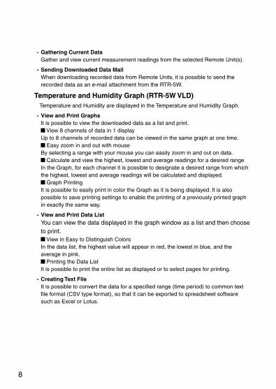
- Gathering Current Data Gather and view current measurement readings from the selected Remote Unit(s).
- Sending Downloaded Data Mail When downloading recorded data from Remote Units, it is possible to send the recorded data as an e-mail attachment from the RTR-5W.
Temperature and Humidity Graph (RTR-5W VLD) Temperature and Humidity are displayed in the Temperature and Humidity Graph.
- View and Print GraphsIt is possible to view the downloaded data as a list and print.
View 8 channels of data in 1 display Up to 8 channels of recorded data can be viewed in the same graph at one time.
Easy zoom in and out with mouse By selecting a range with your mouse you can easily zoom in and out on data.
Calculate and view the highest, lowest and average readings for a desired range In the Graph, for each channel it is possible to designate a desired range from which the highest, lowest and average readings will be calculated and displayed.
Graph PrintingIt is possible to easily print in color the Graph as it is being displayed. It is also possible to save printing settings to enable the printing of a previously printed graph in exactly the same way.
- View and Print Data ListYou can view the data displayed in the graph window as a list and then choose to print.
View in Easy to Distinguish ColorsIn the data list, the highest value will appear in red, the lowest in blue, and the average in pink.
Printing the Data List It is possible to print the entire list as displayed or to select pages for printing.
- Creating Text FileIt is possible to convert the data for a specified range (time period) to common text file format (CSV type format), so that it can be exported to spreadsheet software such as Excel or Lotus.
9
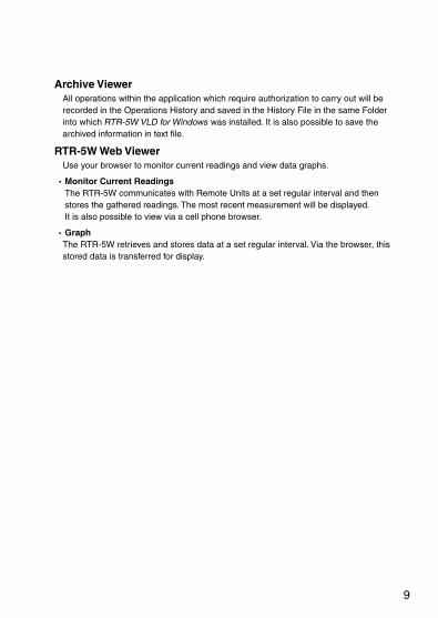
Archive Viewer All operations within the application which require authorization to carry out will be recorded in the Operations History and saved in the History File in the same Folder into which RTR-5W VLD for Windows was installed. It is also possible to save the archived information in text file.
RTR-5W Web ViewerUse your browser to monitor current readings and view data graphs.
- Monitor Current ReadingsThe RTR-5W communicates with Remote Units at a set regular interval and then stores the gathered readings. The most recent measurement will be displayed. It is also possible to view via a cell phone browser.
- GraphThe RTR-5W retrieves and stores data at a set regular interval. Via the browser, this stored data is transferred for display.

10
Before Using... *When using an RTR-50 as a Repeater
Thank you for purchasing this product. Please be careful about the procedures for Installation. (For USB communication between your computer and an RTR-50) The application and USB device driver must be installed for USB communication between your computer and an RTR-50. Before connecting an RTR-50, make sure to install the application and USB device driver into your computer. If you connect an RTR-50 to the computer before installing, the USB device driver may not be installed properly. If you have connected an RTR-50 to your computer before installing the USB device driver, make sure to click the [Cancel] button in the Wizard window when it pops up on the computer display. Then disconnect the USB cable from the RTR-50. For derails about the USB driver installation, see the "Repeater Registration" - "Installing the USB Device Driver" (p.65).
11
Outline of Use
Basic Operation
Getting Ready
1. Prepare the Data Loggers you wish to use as Remote Units.
Get the units ready for measuring by connecting the proper sensors and installing the proper batteries.
2. Getting the RTR-5W Ready to Use
Get the unit ready for communication by connecting the network cable and AC adaptor. * If you wish to use a Repeater, please get an RTR-50 (Repeater) ready to use.
3. Checking your Operating Environment
You also need to check your computer and network setup and be sure to prepare any necessary devices like routers to enable connection to your access point.
4. Connecting to a Network
Connect the RTR-5W to the desired network. See p. 25-26 for connection examples of how to connect directly to your computer or use a router. * Even if you are planning to use a wireless LAN, it is necessary to make the initial settings via a
wired connection.
5. Installing RTR-5W VLD for Windows
To enable set up, install the RTR-5W VLD for Windows into your computer. By installing RTR-5W VLD for Windows, all of the following applications will be installed: User Management Tools for helping with all aspects of the management of user information including user registration and making user operation authorization settings, Network Settings Utility (VLD) for making network settings, RTR-5W (VLD) Module for setting up Remote Units, making recording settings and other operational settings, Temperature / Humidity Graph (RTR-5W VLD) for viewing various types of recorded data, and Archive Viewer for viewing an operations history.

12
Initialization Settings
1. User Registration ...from User Management Tools
Setup and register all User ID's and Passwords that will be necessary for logging into the various RTR-5W VLD for Windows applications, and register which operations will require operation authorization.
2. Network Initialization Settings ...from Network Settings Utility
To connect to a network, it is necessary to enter an "IP address" and "Subnet Mask" that are appropriate for your network. Under Network Initialization Settings make the appropriate settings for your "IP address" and "Subnet Mask". More detailed settings can be made in [Detailed Network Settings].
3. Remote Unit Registration ...from RTR-5W (VLD) Module
In order to carry out wireless communication between an RTR-5W Base Station and a Remote Unit, please register Data Loggers as Remote Units as follows.
Create a LocationCreate GroupsRegister a Remote UnitDepending on the communication status, register and position a Repeater
Up to 64 Remote Units can be registered to one Location.

13
Basic Operations
1. Recording Settings ...from RTR-5W (VLD) Module
By setting the Recording Interval, the Recording Start Date / Time and the Recording Mode, recording will begin at the set date and time. * When using RTR-52Pt, make all necessary sensor settings.
2. Download Data ...from RTR-5W (VLD) for Windows
Data recorded in the Remote Unit will be downloaded and saved in your computer as a data file. Downloaded temperature and humidity data can be viewed in Temp / Humidity Graph.
Graph Display
Temperature and Humidity Graph (RTR-5W VLD)
Temperature and Humidity data can be displayed in the same Temperature and Humidity Graph. (Up to 8 channels of data) You can view the data displayed in the graph window as a list also choose to print. It is also possible to convert the data to common text file format (CSV type format).

14
Other Functions
View Operations History ...from Archive Viewer
Displays the operations history for this software. It is possible to search through archival records by Operation, User ID, and Operation Date and view only those records.
Warning Monitoring Settings ...from RTR-5W (VLD) Module
Monitoring at each Location for warnings is carried out and if any of the gathered data exceeds the set limit, a notification can be sent via e-mail to your computer or cellular phone. Also, because there is a built-in external output terminal, it is possible to connect to an external device, such an alarm or light, so that a notification of a warning can be seen or heard onsite.
Auto Download Settings ...from RTR-5W (VLD) Module
The downloading of data can be set to be automatically carried out at a specified time or at a set interval of time. * For Auto download to occur at a set time, it is necessary for RTR-5W (VLD) Module to be open.
Gather Current Data ...from RTR-5W (VLD) Module
RTR-5W communicates with Remote Units to gather and display the current measurement readings. Also, by setting a communication interval, the current readings will be continuously gathered and displayed at that interval.
Send Downloaded Data Mail Settings ...from RTR-5W (VLD) Module
Data recorded by a Remote Unit will be sent from the RTR-5W as a mail attachment in a specific format that can be opened by T&D graph application or in an original binary format.
Monitor Current Readings ...RTR-5W Web Viewer
The RTR-5W retrieves and stores data at a regular interval set in [Location (RTR-5W) Properties]. The most recent measurement reading(s) can be viewed in the browser.
Graph ...RTR-5W Web Viewer
The RTR-5W retrieves and stores data at a regular interval set in [Location (RTR-5W) Properties]. This stored data transfer can be viewed in graph form via a browser.

15
Software Operations Table
RTR-5W (VLD) Module
RT
R-5W
(VLD
) Module
[File]menu
Open Temp/Humid GraphText Data Output Settings
[View]menu
Expand to Whole TreeProgrammes Auto DownloadView LogStore in Task TrayDisplay Format Settings
[Registration/Administration]
menu
Create Locations / PropertiesCreate Groups / PropertiesRemote Unit Registration / Properties / InitializationRepeater RegistrationDelete from Tree
[Settings]menu
Start / Stop RecordingStart / Stop WarningBattery Life Warning SettingsMail Settings for DownloadSend Group / Remote InfoRTR-52Pt Sensor Settings (Optical Communication)Adjustment Settings (Optical Communication)View Script Version
[Data]menu
Download DataDownload Data (Optical Communication)Gather Current Data...View Remote Unit Battery Level
16
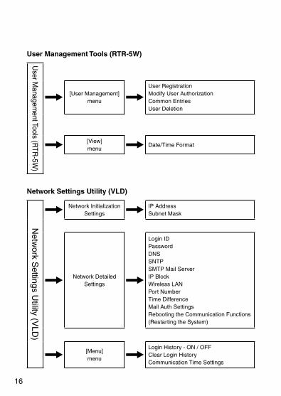
User Management Tools (RTR-5W)
User M
anagement Tools (R
TR-5W
)
[User Management]menu
User RegistrationModify User AuthorizationCommon EntriesUser Deletion
[View]menu
Date/Time Format
Network Settings Utility (VLD)
Netw
ork Settings U
tility (VLD
)
Network Initialization Settings
IP AddressSubnet Mask
Network DetailedSettings
Login IDPasswordDNSSNTPSMTP Mail ServerIP BlockWireless LANPort NumberTime DifferenceMail Auth SettingsRebooting the Communication Functions(Restarting the System)
[Menu]menu
Login History - ON / OFFClear Login HistoryCommunication Time Settings

17
Archive Viewer (RTR-5W)
Archive V
iewer (R
TR
-5W)
[File]menu
Open Archive FileSave Archive File
[Operations]menu
Filters
[View]menu
Date/Time FormatRevise
RTR-5W Web Viewer
RT
R-5W
Web V
iewer
Monitor Current Readings
Graph

18
19
Getting Ready
This section describes how to get the RTR-5W ready to use.

20
Getting the RTR-5W Ready to Use
Connect the supplied AC adaptor * To ensure that the communication cable is properly connected make sure that the
plugs are completely inserted.
NOTE:- Do not use an AC adaptor other than the one that is supplied with the product. Doing so may
cause fire or other trouble. - Insert the AC adaptor plug into an AC 100V socket. Inserting the plug into a socket with different
voltage may cause fire or other trouble. - Do not insert or pull out the AC adaptor plug with wet hands or if there are water drops on the
plug; it may cause electrocution. This may cause electrocution.
Connect the supplied LAN cable. * To ensure that the communication cable is properly connected make sure that the
plugs are completely inserted.
21
Communicating with the Data Logger
It is possible to communicate between an RTR-5W base station and RTR-5 Series Data Loggers by two methods: "Optical Communication" and "Wireless Communication".
Communicating with a Data Logger via Optical Communication Optical communication can be carried out by placing an RTR-5 Series Data Logger face down on the RTR-5W so that the optical communication areas meet.
Place a Data Logger facedown on the RTR-5W
Optical Communication Area
Communicating with a Data Logger via Wireless Communication Communication is carried out with RTR-5 Series Data Loggers via special short-range wireless communication. In order to carry out Wireless Communication, use the application RTR-5W (VLD) for Windows to register the Data Loggers as Remote Units of the RTR-5W Base Station.
* The wireless communication range, if unobstructed and direct, is about 100 meters [330 ft].

22
External Output
Connecting the Signal Wire
1. Prepare a 0.5 - 0.9 single type wire and remove the covering to about 10mm from the tip.
2. Using a screwdriver or other such tool, while pressing down on the terminal button <B> at the back of the unit, insert the wire into the hole <A>.
<A>
<B>
Enlarged view of Wire Connection Terminal
External Output : With Warning ONOFF-State Voltage AC/DC 50V or belowON-State Current 0.1A or belowON-State Resistance 35
Useable WiresSingle wire: 0.4 - 1.0 (AWG26 - 18)Twisted wire: 0.3mm2 - 0.75mm2 (AWG22 - 20) Single wire diameter 0.18 or aboveStandard Stripping Length: 10mmCompatible Connector Tool: Screwdriver (Shaft: 0.3 / Blade Tip Width: 2.6)
Removing an Input Signal WireIf you wish to remove an input signal wire, press down on the <B> button with a screwdriver and pull out the wire.
NOTE:Please be careful when pulling out the wire.

23
Checking your Operating Environment
To properly use the logger, the following operational environment is necessary.
PC Operating Environment
OS Microsoft Windows 7 32/64bit EnglishMicrosoft Windows Vista 32bit EnglishMicrosoft Windows XP 32bit (SP2 or above) English
* For installation, it is necessary to have Administrator (Computer Administrator) rights.
PC / CPU A Stable Windows Operating EnvironmentLAN·TCP/IP Communication Possible
Memory Enough memory to stably operate Windows®
Hard DiskMore than 10MB free space (More free space is necessary for data)
Monitor SVGA (higher than 800 600 recommended)
LAN 100BASE-TX or 10BASE-T Twisted pair cable conforming to Category 5 (STP/UTP)
Web Browser Internet Explorer 6.0 or higher (English)
Using a LANConnect the provided LAN cable to the HUB that is connected to your computer.
Connecting Directly to a PCConnect the RTR-5W to your computer with a LAN cross cable.
* LAN cross (reverse) cables are not included with the product. Please purchase separately.
Connecting to a Wireless LAN via CF Card If you are using a Wireless LAN card, please use a Wireless LAN access point (Combined Wireless LAN and Hub OK) to connect the RTR-5W to a network.
* For information and updates concerning which wireless LAN cards can be used, please contact your local T&D dealer or representative.

24
Using the Internet In order to connect to the Internet, you must first make arrangements with a provider for a line. It may also be necessary to get an IP address or domain and make domain name server and other settings. For more details about various settings, it is best, if present, to contact the network administrator. To get more details about your Internet connection and setup, please contact your provider.

25
Connecting to a Network
The following are some ways to connect an RTR-5W to a network. Please select the connection method that suits your network environment.
Connecting to a HUB for in-company Communication* To ensure proper connection make sure that the plug is completely inserted.
Connection Example
Connecting Directly to PC for Communication Do not use the supplied cable; please purchase a cross LAN cable separately.
* To ensure proper connection make sure that the plug is completely inserted.
Connection Example
26
Connecting to a Wireless LAN Insert a Wireless LAN card into the RTR-5W to carry out communication. By using a Wireless LAN card, it is possible to carry out communication in places where LAN wiring is difficult or troublesome.
* To ensure proper connection make sure that the wireless LAN card is completely inserted.
NOTE:- Before you insert or take out the LAN card, make sure that the AC adaptor is unplugged. - For information and updates concerning which wireless LAN cards can be used please see our
Website.
Connection Example

27
Connecting to the Internet
In order to connect the RTR-5W to the Internet you must first set up an Internet connection environment by making arrangements with a provider for a line and get a global IP address and domain. Also, if necessary, make all domain name server and/or router settings. For more details about various settings, it is best, if present, to contact the network administrator. To get more details about a global IP address and domain, please contact your provider. The following are examples of connection methods. Please select the connection method that suits your network environment.
Connection ExampleUsing the RTR-5W on the Internet
In order to access the RTR-5W from your browser, enter the Global IP address that has been assigned to the RTR-5W in your browser's URL bar following [http://]. The RTR-5W will be called via a router or the Internet provider. The RTR-5W which received the access request will return data to the computer which sent the access request.
Using a Domain Name (ex: rtr-5w.net)
In order to access the RTR-5W from your browser, enter the Domain Name (Ex : rtr-5w.net) that has been assigned to the RTR-5W in your browser's URL bar following [http://]. The Domain Name that was entered in the URL bar is converted by the DNS server into an IP address and the RTR-5W is called. The RTR-5W which received the access request will return data to the computer which sent the access request.

28
Using Mail via LAN
The RTR-5W accesses the SMTP server and sends mail to the server. The SMTP server delivers the mail sent from the RTR-5W, according to the address, to a POP server. The POP server receives the delivered mail from the SMTP server and stores it in the appropriate mailbox for that mail address.
Your computer accesses the POP server where the mail is stored and receives mail in the computer's mailbox.
NOTE:When you are using a LAN to send and get warning mail, it is necessary to have set up an SMTP server (for sending) and a POP or IMAP server (for receiving) in the network.

29
Sending Internet Mail
The RTR-5W, via a router or provider, accesses an SMTP server that exists on the Internet and sends mail to the SMTP server. The SMTP server delivers the mail sent from the RTR-5W, according to the address, to a POP server. The POP server receives the delivered mail from the SMTP server and stores it in the appropriate mailbox for that mail address.
Your computer accesses the POP server where the mail is stored and receives mail in the computer's mailbox.
NOTE:In order to connect to the Internet, please make the necessary router (LAN) settings.

30
Installation
Install the provided software.
- Is Windows® operating properly? If Windows® is not operating properly, RTR-5W VLD for Windows may not be installed correctly or it may not operate properly.
- Please quit all other applications. If other programs are open, please close and quit all of them, making sure to quit all Quick Start programs such as a virus checker. If you have any permanently active software, such as a virus check or scan program in your computer, make sure to also quit it.
- To install RTR-5W VLD for Windows, it is necessary to have Administrator rights (Computer Administrator) for the computer in which you wish to install it.
* The layout of the installation window for "Windows 7" closely resembles that of "Windows Vista". When using "Windows 7" to install the Software, please refer to the installation instructions found under "Windows Vista" in the User’s Manual provided with the product and follow on-screen messages as they appear.
For information about operating the software, please carefully read the important notices and instructions found in the User’s Manual.
For Windows® XP
1. Open Windows®.
2. Insert the attached CD-ROM in the CD-ROM drive. In a few seconds, the [Install Program] window will appear.
* If that window does not automatically open, please open it by double clicking the CD-ROM icon in [My Computer] on your desktop.
[Excute]ButtonClick here
3. Select [Install RTR-5W VLD for Windows] and click the [Execute] button to start the installation.

31
4. A screen will appear where you can enter the product serial number. The product serial number is printed on the sticker inside the software CD-ROM package. Make sure that it is properly entered and click the [Next] button. Continue the installation by following the directions as they appear. After installation has been completed, [RTR-5W VLD for Windows] will be registered in the Window's [Start] Menu.
For Windows® Vista / 7
1. Open Windows®.
2. Insert the attached CD-ROM in the CD-ROM drive. * If the [Auto Play] window appears, under [Install or run program], click on [Run Start.
exe]. For some applications the above may appear as [Run First.exe].
3. The [Install Program] window will appear. * If that window does not automatically open, please open it by double clicking on the
CD-ROM icon in [Computer].
[Excute]ButtonClick here
32
4. Select [Install RTR-5W VLD for Windows] and click the [Execute] button. Then the [User Account Controls] window will appear.
5. Click [Next] to start the installation.
6. A screen will appear where you can enter the product serial number. The product serial number is printed on the sticker inside the software CD-ROM package. Make sure that it is properly entered and click the [Next] button. Continue the installation by following the directions as they appear.
7. After the application has been installed, the following message will appear. Click the [Install] button.
* After installation has been completed, RTR-5W VLD for Windows will be registered in the Window's [Start] Menu.

33
Initialization Settings
Here you can make User Registration and all Network Settings.

34
Using User Management Tools
To carry out various operations in RTR-5W VLD for Windows, it is necessary to have a User ID, a Password and operation authorization. In User Management Tools, User ID's, Passwords and Operation Authorization Registration settings can be made for each user.
How to Open From the list of programs in the Window's Start Menu, click on [RTR-5W VLD for Windows] - [User Management Tools].
Logging into the [User Management Tools] Only the Administrator (User ID: admin) can enter and login to [User Management Tools]. First, login using the default User ID: admin and Password: passwd.
* Passwords can be changed using [Modify User Authorization].
User Management Tools FunctionsThe following operations can be carried out using the User Management Tools.
- User Registration- User Operation Authorization Settings- Common Entry Settings- Delete User * It is impossible to delete the administrator.
In the User ID List, the User ID for the authorized administrator will appear in red letters.
Registration Info
User ID List
Administrator

35
Making User Registrations
1. In the [User Management] Menu, select [User Registration] to display the window in which you can make User ID and Password entries. Enter User ID and Password.
- The User ID and Password can be made up of between 5 and 16 characters using alphabet, numbers, "-" (hyphens) and "_" (underscores).
- A distinction will be made between upper and lower case alphabet, so please be careful. Ex. abc123 and ABC123 will be treated as different.
- Any already registered and in use User ID cannot be used in any other registration.
Enter User ID and Password
[OK]Button
Make User Operation Authorization Settings
2. Make User Operation Authorization Settings for the operation of each application.
It is possible to make settings to restrict the carrying out of any operations considered critical. So, even if a user is able to login without the necessary authorization that user will be unable to carry out various operations.
- The memo area can contain up to 64 characters. - A User without any authorizations cannot be registered.
3. Click the [OK] button to complete the settings.
36
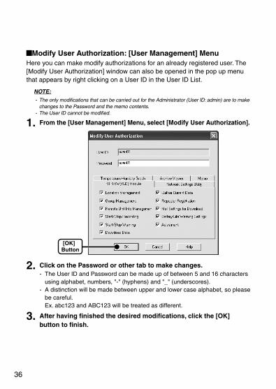
Modify User Authorization: [User Management] Menu Here you can make modify authorizations for an already registered user. The [Modify User Authorization] window can also be opened in the pop up menu that appears by right clicking on a User ID in the User ID List.
NOTE:- The only modifications that can be carried out for the Administrator (User ID: admin) are to make
changes to the Password and the memo contents. - The User ID cannot be modified.
1. From the [User Management] Menu, select [Modify User Authorization].
[OK]Button
2. Click on the Password or other tab to make changes. - The User ID and Password can be made up of between 5 and 16 characters
using alphabet, numbers, "-" (hyphens) and "_" (underscores). - A distinction will be made between upper and lower case alphabet, so please
be careful. Ex. abc123 and ABC123 will be treated as different.
3. After having finished the desired modifications, click the [OK] button to finish.
37
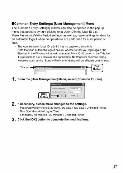
Common Entry Settings: [User Management] Menu The [Common Entry Settings] window can also be opened in the pop up menu that appears by right clicking on a User ID in the User ID List. Make Password Validity Period settings, as well as, make settings to allow for an automatic logout when no operations are performed for a set period of time.
- The Administrator (User ID: admin) has no password time-limit. - Note that if an automatic logout occurs, whether or not you login again, the
Title bar in the Window will remain operable. From [Quit] button in the Title bar it is possible to quit and close the application. No Windows common dialog windows, such as the "Specify File Name" dialog will be affected by a timeout.
[Quit]Button
Title bar
1. From the [User Management] Menu, select [Common Entries].
[OK]Button
2. If necessary, please make changes to the settings. - Password Validity Period: 30 days / 90 days / 120 days / Unlimited Period - Non Operation Auto Logout Time:
5 minutes / 10 minutes / 20 minutes / Unlimited Period
3. Click the [OK] button to complete the modifications.

38
User Deletion: [User Management] Menu Here you can delete an already registered user. The [User Deletion] window can also be opened in the pop up menu that appears by right clicking on a User ID in the User ID List.
NOTE:The Administrator (User ID: admin) cannot be deleted.
1. From the User ID list, select the User you wish to delete.
2. From the [User Management] Menu, select [User Deletion].
3. A message will appear and then click the [OK] button to complete the deletion process.
Clock Format: [View] Menu Use this to change the format in which time is displayed.
1. In the [View] Menu, move the mouse to [Clock Format] and select the format in which you wish to display time.
2. By clicking the desired format, the setting will be completed.
39
Using the Network Settings Utility (VLD)
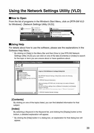
How to Open From the list of programs in the Window's Start Menu, click on [RTR-5W VLD for Windows] - [Network Settings Utility (VLD)].
Using Help For details about how to use the software, please see the explanations in the Software Help Menu.
* By clicking on [Help] in the Menu Bar and then [How to Use RTR-5W Network Settings Utility (VLD)] you can click on one of the tabs [Contents] or [Index] to search for the topic or term you are unsure about or have questions about.
[Contents]By clicking on one of the topics listed, you can find detailed information for that subject.
[Index]By selecting a Keyword in the Keyword list, and clicking the [Display] button at the bottom, a detailed explanation will appear.
* By clicking the [Help] button in a dialog box, an explanation for that dialog box will appear.

40
Network Settings Utility (VLD) Functions The Network Settings Utility (VLD) contains the following functions:
Network Initialization Settings After purchasing an RTR-5W unit, the first step is to make all Network Initialization Settings including assigning an IP Address and a Subnet Mask.
Detailed Network Settings The reception of RTR-5W settings and more detailed network settings can be made here. In the SNTP settings (for automatic clock settings), it is possible to make settings so that the RTR-5W clock settings can be automatically received from NTP server. Clock settings can be made directly using RTR-5W (VLD) Module software, but if an RTR-5W is rebooted (restarted) the clock settings will be initialized. However, by making settings to enable the SNTP server it is possible to have the clock automatically reset to the current time upon rebooting.
NOTE:- Please open the Network Settings Utility (VLD) from only one computer at a time in the same
network (same broadcast domain). - If you open the Network Settings Utility (VLD) on multiple computers in the same network, it may
not work properly.
[Menu]
[Menu] - [Login History] If you wish to disable the History Function, select [Login History] >> [OFF].
[Menu] - [Clear Login History] Use this to erase the entire login history.
[Menu] - [Communication Time Settings] It is possible to change the communication time for all types of communication depending on your network environment.
41
Network Initialization Settings
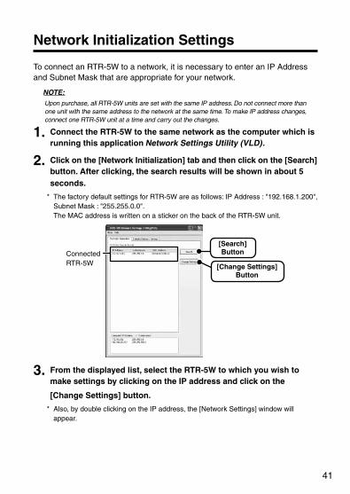
To connect an RTR-5W to a network, it is necessary to enter an IP Address and Subnet Mask that are appropriate for your network.
NOTE:Upon purchase, all RTR-5W units are set with the same IP address. Do not connect more than one unit with the same address to the network at the same time. To make IP address changes, connect one RTR-5W unit at a time and carry out the changes.
1. Connect the RTR-5W to the same network as the computer which is running this application Network Settings Utility (VLD).
2. Click on the [Network Initialization] tab and then click on the [Search] button. After clicking, the search results will be shown in about 5 seconds.
* The factory default settings for RTR-5W are as follows: IP Address : "192.168.1.200", Subnet Mask : "255.255.0.0". The MAC address is written on a sticker on the back of the RTR-5W unit.
ConnectedRTR-5W
[Search]Button
[Change Settings]Button
3. From the displayed list, select the RTR-5W to which you wish to make settings by clicking on the IP address and click on the
[Change Settings] button.
* Also, by double clicking on the IP address, the [Network Settings] window will appear.
42
4. Enter an IP Address and Subnet Mask. * Make sure to enter an IP Address and Subnet Mask that are appropriate for your
network.
NOTE:Do not use the same IP address for two different units. It may cause abnormalities to the entire network system.
Enter the " IP Address" and "Subnet Mask"
[Send]Button
Enter the "Login ID" and "Password"
5. After entering the above, next, enter the login ID and Password. * The RTR-5W factory default Login ID is "wsc-user" and the Password is "wsc-
passwd". Make any necessary changes to the Login ID and Password in the "Detailed Network Settings". See pp. 43 - 44 for details.
6. After checking for entry errors, click the [Send] button. After transmission has been completed a message will appear. Click the [OK] button to finish.
* After settings are completed the RTR-5W will automatically restart. During the restarting process, a search cannot be performed, even if you click the [Search] button. Please try again after 30 seconds.
If no units are detected - Check the connection between the computer and the RTR-5W. - Check the hub power switch and the network cable type. - If some network environments, it may be necessary to make changes to the
IP address and subnet mask at the computer side in order to carry out a search. For details, see pp. 134 - 139 "Checking and Making Changes to Computer Network Settings".
- Do not use a LAN card which has not been formatted.

43
Detailed Network Settings
After making the network initialization settings for the RTR-5W, the reception of RTR-5W settings and more detailed network settings can be made.
* Before making any of these settings, please make sure that the RTR-5W is set with the proper IP address.
Receiving the Settings
1. Click the [Detailed Network Settings] tab.
2. In the "Receive Settings" Area, enter the information for the RTR-5W you wish to make settings for and click the [Get Settings] button. The current settings will appear.
A list that shows all of the IP addresses and domain names with which successful communication has occurred until now can be viewed in the [Settings History] pull down menu. If you select an IP address or domain name here, the Login ID, Password and Port Number will be entered automatically.
* Note that if you have turned [OFF] the [Login History] in the [Menu] or if you have deleted the Login history by having clicked [Clear Login History], the Settings History will not appear.
[Settings History]
Enter info for the RTR-5W you wish to make settings in
[Get Settings]Button
[Change Settings]Button

44
Making Settings (Changes)
1. In the [Detailed Network Settings] window, click the [Change Settings] button, and make any necessary changes.
* For details about making settings (changes), see the [Help] Menu in the [Network Settings Utility (VLD)].
[Send Settings]Button
Enter info for the RTR-5W you wish to make settings in
2. After making the settings, enter the info for the recipient of the settings and click the [Send Settings] button.
3. A message will appear asking you if it is OK to restart the system. Click the [Yes] button to restart.
* The new settings will not become valid until the RTR-5W communication function is restarted.
[OK]Button
4. After restarting has finished, the settings will have been completed.
45
[Mail Auth Settings] ButtonIn order to send warning report mails from the RTR-5W, it is necessary to make the following settings if you are using an SMTP server that requires SMTP authentication or POP before SMTP.
1. In the [Detailed Network Settings] window, click the [Mail Auth Settings] button and make any necessary settings changes.
* For details about making settings changes, see the [Help] Menu in the [Network Settings Utility (VLD)].
[Mail Auth Settings]Button
2. After having made the desired settings, click the [OK] button.
[OK]Button
3. In the [Detailed Network Settings] window, click the [Send Settings] button and reactivate communication in the RTR-5W.
* The new settings will not become valid until the RTR-5W communication function is restarted.

46
[Re-Activate Communication] ButtonIf the browser does not open, wireless communication continually results in failure, or if any errors occur during communication, click the [Re-activate Communication] button. Note that by restarting, the data transfer graph in the RTR-5W Web Viewer will also be reset.
NOTE:By clicking the [Send Settings] button or the [Re-activate Communication] button over and over, communication may become impossible. Please try again after 20 seconds.
[Re-active Communication ]Button

47
Returning the Network Settings to the Factory Default Settings
If you have forgotten the IP address or the password you can easily return the logger to the default factory settings.
1. Pull out the AC adaptor plug from the RTR-5W logger.
2. Press in the <RESET> button on the RTR-5W logger with a pointed object and reconnect the AC adaptor.
<RESET> Button
3. When the <POWER> lamp on the face of the RTR-5W logger starts blinking, release the <RESET> button and the unit will have been returned to the factory default settings.

48
RTR-5W Clock Settings
If the clock settings for the RTR-5W are not set correctly, the clock in the RTR-5W Web Viewer and the time of warnings will also be incorrect. Please make sure to set correctly before beginning to use.
Automatic Setting of the Clock Normally, when an RTR-5W is rebooted the clock settings will be initialized. However, by making settings to enable the SNTP server it is possible to have the clock automatically reset to the current time upon rebooting.
* The SNTP (NTP) server is a server that automatically adjusts the clock settings of a terminal on a network.
1. Open the Network Settings Utility (VLD), click on the [Detailed Network Settings] tab, and gather the settings for the RTR-5W that you wish to make settings for.
2. Click the [Change Settings] button and the window will appear where you can make changes to the settings.
SNTP Settings
3. Under [SNTP Settings], click "ON" to change the setting.
How to find an NTP server- If you are connected to an intra company LAN, you may already have an NTP
server for your network. Please ask your network administrator for details. - If you are connected to the Internet, some providers will have an NTP server
open to the public. Please ask your provider for details. - If you wish to use an NTP server that is open to the general public on the
Internet, by running a search for "NTP Server" on any search engine such as Yahoo or Google you will be able to find many such services. Many universities or scientific facilities will have an NTP server open to the public.

49
Make sure to use the server which is closet to your location. Also, in this case it is necessary to make settings for the gateway address. Moreover, please make sure to check whether connection is free and without limitation. It should also be noted that depending on your Internet connection and your firewall settings, the NTP packet may be prohibited from being accepted into your system.
4. After making the settings, enter the info for the recipient of the settings and click the [Send Settings] button.
[Send Settings]Button
Enter the information for the recipient
5. A message will appear asking you if it is OK to restart the system. Click the [Yes] button to restart.
* The new settings will not become valid until the RTR-5W communication function is restarted.
[OK]Button
6. After restarting has finished, the settings will have been completed.
50
Making the Clock Settings Manually* If you wish to manually set the clock, please carry out settings only after having
created a Location.
NOTE:If you make clock settings manually, the clock will lose its settings upon removal of the AC adaptor or after restarting the system. Hence, it is necessary to reset the clock after having restarted the system or having removed AC power.
1. Open RTR-5W (VLD) Module.
2. Open the Properties for the Location (RTR-5W) you wish to make settings for.
In the [Registration / Administration] Menu, select [Location (RTR-5W) Properties] or by right clicking on the Location icon, a popup menu will appear where you can select [Location (RTR-5W) Properties] to display the properties window.
[Set Clock]Button
3. Click the [Set Clock] button and set the current date and time. - If you wish to set to the same time as your computer clock, select [Set
to the Computer Clock].* Make sure that the computer clock settings are correct before choosing this
method.
- If you wish to directly enter a specified date and time, select [Set to Specified Time] and enter the desired settings.
[Set]Button
4. Click the [Set] button to send the settings to the RTR-5W and complete the settings.

51
Basic Operations
This section describes and explains how to carry out the following basic operations. - Remote Unit Registration- Repeater Registration- Recording Settings- Gathering Current Data - Downloading Recorded Data- Reading Operations History File - Auto-Download Settings- Warning Monitoring- Battery Life Warning Settings - Mail Settings for Download

52
How to operate RTR-5W (VLD) Module
How to OpenFrom the list of programs in the Window's Start Menu, click on [RTR-5W VLD for Windows] - [RTR-5W (VLD) Module] to open.
Using HelpFor details about how to use the software, please see the explanations in the Software Help Menu.
* In the Menu Bar, click [Help] - [Search by Topic], then click on one of the tabs [Contents], [Index], or [Search] to search for the topic or term you are unsure about or have questions about.
[Contents]By clicking on one of the topics listed, you can find detailed information for that subject.
[Index] By selecting a Keyword in the Keyword list, and clicking the [Display] button at the bottom, a detailed explanation will appear.
[Search] Enter the keyword you wish to search for and click the [List Topics] button. All topics that contain the keyword will be displayed. By selecting a topic and clicking the [Display] button at the bottom, a detailed explanation will appear.
* By clicking the [Help] button in a dialog box, an explanation for that dialog box will appear.

53
RTR-5W (VLD) Module Functions RTR-5W (VLD) Module is designed to allow the user to utilize RTR-5 Series Data Loggers via the RTR-5W Base Station. From the main window it is possible to carry out the various tasks such as Registrations, Recording and Warning Monitoring Settings, as well as the Downloading of Data. Management of all devices is carried in the application main window using a tree format with loggers being registered to Groups and Groups belonging to Locations (RTR-5W).
Menu Bar
Administration Tree
Toolbar
Settings Contents Info Area
Menu BarMenus are lined up which contain various commands. They are used to view data or to make settings for the various functions in each menu.
ToolbarButtons appear for frequently used commands.
Administration TreeIn the tree all registered Locations (item at the top of each tree list), Groups and Remote Units can be viewed and managed. By right clicking on an icon, a menu will appear with commands for that type of unit.
Settings Contents Info AreaBy clicking on an icon (Location, Group, Remote Unit), the settings info for that item will be displayed.

54
Remote Unit / Repeater Installation Procedures
1. Connect the provided AC adaptor to the Base Unit (RTR-5W), and connect the LAN cable to the PC.
For more details see p.20 "Getting the RTR-5W Ready to Use"
2. Register Groups and Remote Units. Register all Remote Units to be placed.
For more details see p.57 "Remote Unit Registration".
3. Register Repeater Names and Relay Routes.
For more details see p.65 "Repeater Registration".
NOTE:There is no need to register a Repeater if there are no Repeaters between a Remote Unit and the RTR-50 Base Unit. However, if communication cannot be successfully carried out due to poor radio wave reception, please place Repeater(s) between the Remote Unit and the Base Unit.

55
About Repeaters A "Repeater" is defined as an RTR-50 Wireless Communication Port that has been registered as a "Repeater" to act as a relay for Wireless Communication between a Base Unit and Remote Units from our RTR-5 Series.
[Limitations when using a Repeater] Although it is logically possible to register up to 250 Repeaters in a route, each additional Repeater added to the route will proportionately increase communication time. To download the full amount of data from one Remote Unit without any Repeaters will take about 7 minutes, hence with the addition of each Repeater the amount of necessary communication time will be increased by 7 minutes. If there are 10 units, the necessary time would reach about 70 minutes. Communication time for an RTR-50 is set to be limited to no longer than 2 hours and 30 minutes. For this reason, if there were 250 Repeaters it would be impossible to download the full data of even one Remote Unit. If it is necessary to download a unit with full data, then it is also necessary to have no more than 20 Repeaters. For all communications other than downloading, no conflict with the time limitation will occur, even if there are 250 Repeaters present.
[Image of Repeater Registration]

56
Once the registration of a Repeater is complete, a Repeater Number will automatically be assigned to each Repeater. Also, when carrying out Repeater Registration it is possible to assign a "Relay Route Name" that can be used to make sure that data is transmitted through a multiple number of Repeaters in the specified route.
NOTE:- It is possible to set up so that more than one Repeater acts as a relay for the same Remote Units.
However because wireless communication is carried out in Groups of Remote Units, the same Group will be relayed through different Repeaters causing inefficiency and an increase in the amount of communication time to more than necessary. In order to reduce the communication time, please design Relay Routes so that a particular Group of Remote Units uses the same Repeater(s) as shown in the figure on page 55.
- A Repeater Number will be automatically assigned to Repeaters in the order that they were registered to each Route. Communication among Repeaters will occur in sequence from the one that is closest to the Base Unit. Please keep that in mind when placing the Repeaters.
Communication Sequence Order EX:
Communication will occur sequentially from the first Repeater as shown above. If the Repeaters are not arranged in numerical sequence from the Base Unit, the communication route will be as seen below. This will cause not only the communica-tion distance to increase but also the communication time to increase to longer than necessary.
4. After each Registration has been completed, please check the communication status by carrying out a Wireless Communication Test from the [Repeater Registration] window under [Communica-tion] - [Wireless Communication Test].
* If no Repeater is registered, the current data from all Remote Units will be gathered to confirm the communication status.
57
Remote Unit Registration
In order to carry out Wireless Communication between a Data Logger and an RTR-5W Base Station, it is first necessary to register the Data Logger as a Remote Unit of that RTR-5W.
Creating a Location
1. Open RTR-5W (VLD) Module.
2. In the [Registration / Administration] Menu, click on [Create Location (RTR-5W)] to display a window where you can enter a name for the new Location.
* In the Location name, you cannot use a space, or any of the following characters [\/:,;?"<>|&.#]
Enter the Location Name
[OK]Button
3. After entering the Location Name, by clicking the [OK] button, the Location will be created in the Administration Tree.
Administration Tree
Location Icon
4. Click on the desired Location Icon. In the [Registration / Administration] Menu, select [Location (RTR-5W) Properties] and enter the same IP address that you previously entered when making settings in Network Settings Utility (VLD).
* By right clicking on the Location icon, a popup menu will appear where you can select [Location (RTR-5W) Properties] to display the properties window.

58
[Set]Button
[Access Settings] Area
[Browser Display Settings] Area
[Summer Time Setting]
[Get Time]Button
[Set Clock]Button
[Reboot]Button
Enter the IP Address / Domain assigned when making the network initialization settings.
[Send Summer Time Info to RTR-5W] Button
Access SettingsEnter the IP address (or Domain) for the RTR-5W that was entered in Network Settings Utility (VLD).
Browser Display Settings If necessary, make settings in the [Browser Display Settings] Area.
- Make access possible from a browserIt is possible to make permit / forbid access from a browser.
- Data Gathering Intervals for Data Transfer Graph <Selections: none, 15, 20, 30 minutes, 1, 2, 3, 6, 12, 24 hours>This setting is for the intervals for gathering data when monitoring the current readings via the browser and viewing in simple graph form.
Summer Time SettingIf you wish to allow the location's internal clock to automatically change from Standard Time to Summer Time, check [Automatically adjust the location's internal clock for Summer Time]. By checking this box, settings can be made for automatically changing the internal clock from Standard Time to Summer Time. Summer Time adjustments will be made according to the Time Zone setting which has been made in Windows (time difference from GMT).

59
NOTE:If [Automatically adjust clock for Summer Time] has not been checked in the "Date and Time Properties" Settings in the Control Panel of Windows OS you are using, it will not be possible to make Summer Time setting. In such a case, please check the Settings in "Date and Time Properties" and make any necessary changes.
5. After making entries click the [Set] button to send the settings to the RTR-5W that were entered into the [Access Settings] area and the settings for the Location will be completed.
[Get Time] ButtonClicking this button will start communication with the Location and will retrieve and display the time settings from the Location's internal clock. Due to network delays, this may be a few seconds off from the time you receive the settings.
[Set Clock] ButtonIf SNTP settings have not been made, click this button to make RTR-5W clock settings. In this case, please make sure to reset the internal clock to your local time before using. This is necessary because each time the RTR-5W is rebooted the unit's internal clock is automatically returned to its default setting. See pp. 48 - 50 for details.
[Reboot] ButtonThis will forcibly reboot the RTR-5W.
[Send Summer Time Info to RTR-5W] ButtonClicking this button will send the Summer Time info to the RTR-5W at the selected Location. If a change is made to the [Summer Time Setting], make sure to send the new settings. Note that to activate the Summer Time Setting, the RTR-5W may automatically reboot after the Info has been sent to the RTR-5W. Please read the following "NOTE" about the rebooting of an RTR-5W.
NOTE:- By rebooting an RTR-5W, the unit's internal clock will automatically return to its default setting
(01/01/2004). If an SNTP server is not being used, please make sure to reset the internal clock to your current local time before using.
- By rebooting an RTR-5W, all warning logs, readings and graphs currently displayed in the browser (data files for transfer) will be erased. Note however that, when an RTR-5W is rebooted, the recorded data logged in the Remote Unit will not be affected.

60
How to Check for the Version of Script and Firmware In order to use this software it is necessary to have an updated version of both the script and firmware for the RTR-5W registered at the Location being used. Please use the following method to check the versions being used.
1. Open RTR-5W (VLD) Module.
2. From the [Settings] Menu, select [View Script Version].
3. Place a check next to the Location from which you wish to get the version info from and click the [Script Ver.] button to display the version info.
NOTE:In order to use this software it is necessary to have the following versions- Script Version: 1.70 or above- Firmware Version: 02.00.00 or above If it is necessary to update the script and/or firmware, please go to our Web Site for the latest version. (http://www.tandd.com/support/index.html)
Creating Groups
1. In the [Registration / Administration] Menu, click on [Create Group] to display a window where you can enter a name for the new Group.
* Up to 8 characters can be entered. * In the Location name, you cannot use a space, or any of the following characters
[\/:,;?"<>|&.#].
[OK]ButtonEnter a
Group Name
2. After entering the Group Name, by clicking the [OK] button, the Group will be created in the Administration Tree.

61
Administration Tree
Group Icon
3. Click on the desired Group Icon. In the [Registration / Administration] Menu, select [Group Properties] and assign a Communication Frequency Channel for the selected Group.
* By right clicking on a Group icon, a popup menu will appear where you can select [Group Properties] to display the same window.
Assign a Communication Frequency Channel
[OK]Button
Communication Frequency Channel - It is possible to set one Communication Frequency Channel (channel 0-15) to each
Group. - If a different Group is located nearby and there is a possibility that communication
could occur at the same time, please make sure to set the Communication Frequency Channels for each Group to a different setting. If two Groups use the same Communication Frequency Channel at the same time, there is a great possibility that a communication failure will occur.
- Communication Frequency Channel settings can only be made when registering a new Group. Once a Communication Frequency Channel setting has been made, it cannot be changed.
4. Click the [OK] button to finish the Group settings.

62
Registering a Remote Unit
1. Place a Data Logger face down on the RTR-5W. See p.21 for more details about how to connect.
2. Select the Group in which you wish to register Remote Units from the Registration Tree. In the [Registration / Administration] Menu, select [Remote Unit (RTR-5) Registration] to display the Remote Unit Registration window.
* By right clicking on a Group icon, a popup menu will appear where you can select [Remote Unit Registration] to display the Remote Unit Registration window.
* If an exclamation mark " ! " is next to a Location Icon, make sure to carry out [Send Group / Remote Info] after having made settings.
Administration Tree
Select the Group into which you wish to register a Remote Unit
3. Enter a name for the Remote Unit and click the [Register] button to finish the registration.
[Register]Button
Enter the Remote Unit Name
Remote Units that have already been registered
* If you wish to register other Remote Units, repeat the process as in steps 1~3.

63
Sending Registration Info to an RTR-5W* Make sure to carry out this operation each time changes are made to settings.
1. Select a Location from the Administration Tree, and in the [Settings] Menu, select [Send Group / Remote Info].
[Send]Button
2. Click the [Send] button to send the registration info to the RTR-5W and complete the settings.

64
Wireless Communication Test If no Repeaters exist, gather the current data readings from each Remote Unit and check to make sure that wireless communication is possible between the Remote Units and the RTR-5W Station.
1. Place a Remote Unit in the actual place from which you wish to measure and record data.
* The wireless communication range, if unobstructed and direct, is about 100 meters [330 ft].
2. Select the placed Remote Unit from the Administration Tree, and in the [Data] Menu, select [Gather Current Data].
* By right clicking on the Remote Unit icon, a popup menu will appear where you can select [Gather Current Data] to display the [Gathering Current Data] window.
The selected Remote is displayed
3. Click the [Gather] button to start communication with the Remote Unit and the current data readings will be displayed.
[Gather]Button
If the current readings are not displayed, move the Remote Unit to a different Location and try gathering the current data again.
65
Repeater Registration
In order to add a Repeater to enhance communication between Data Loggers and an RTR-5W Base Station, it is first necessary to register an RTR-50 Wireless Communication Port as a Repeater.
Installing the USB Device Driver* To install RTR-5W VLD for Windows or USB Device Driver, it is necessary to have
Administrator rights (Computer Administrator) for the computer in which you wish to install it.
* When using "Windows 7" to install the USB Device Driver, please refer to the installation instructions found under "Windows Vista" in the User's Manual provided with the product and follow on-screen messages as they appear.
For Windows Vista / 7* When installing the software RTR-5W VLD for Windows, the USB Device Driver will
also be installed automatically.
Checking the USB Device Driver Installation
1. Connect the RTR-50 (Repeater) to the computer with a USB Communication Cable.
* For how to connect to a computer, see the User's Manual that accompanies your RTR-50 Wireless Communication Port.
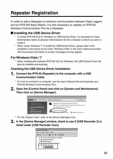
2. Open the [Control Panel] and click on [System and Maintenance]. Then click on [Device Manager].
* For the "Classic View", click on the [Device Manager] icon.
3. In the [Device Manager] window, check to see if [USB Recorder 2] is listed under [USB Recorder Com].
66
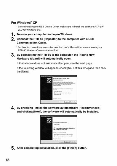
For Windows® XP* Before installing the USB Device Driver, make sure to install the software RTR-5W
VLD for Windows first.
1. Turn on your computer and open Windows.
2. Connect the RTR-50 (Repeater) to the computer with a USB Communication Cable.
* For how to connect to a computer, see the User's Manual that accompanies your RTR-50 Wireless Communication Port.
3. By connecting the RTR-50 to the computer, the [Found New Hardware Wizard] will automatically open.
If that window does not automatically open, see the next page.
If the following window will appear, check [No, not this time] and then click the [Next].
4. By checking [Install the software automatically (Recommended)] and clicking [Next], the software will automatically be installed.
5. After completing installation, click the [Finish] button.

67
If the Device Driver is not automatically detected Follow the directions below to install.
1. Disconnect the USB cable from the RTR-50 logger and then re-connect it.
2. The [Found New Hardware Wizard] will automatically open. If the following window will appear, check [No, not this time] and then click the [Next].
* Windows such as this will not appear for "No Service Pack" and "Service Pack 1" versions of Windows XP.
3. By checking [Install from a list or specific location (Advanced)] and then clicking the [Next] button, the installation process will begin.
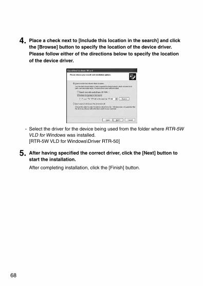
68
4. Place a check next to [Include this location in the search] and click the [Browse] button to specify the location of the device driver. Please follow either of the directions below to specify the location of the device driver.
- Select the driver for the device being used from the folder where RTR-5W VLD for Windows was installed. [RTR-5W VLD for Windows\Driver RTR-50]
5. After having specified the correct driver, click the [Next] button to start the installation.
After completing installation, click the [Finish] button.

69
Checking the USB Device Driver Installation
1. Connect the RTR-50 (Repeater) to the computer with a USB Communication Cable.
* For how to connect to a computer, see the User's Manual that accompanies your RTR-50 Wireless Communication Port.
2. Open the Control Panel and click on [Performance and Maintenance] - [System]; the system properties will be displayed.
3. Click the [Hardware] tab, and then click the [Device Manager] button in the Device Manager Area.
4. In the Device Manager Window, check to see if [USB Recorder 2] is listed under [USB Recorder2 Com].
NOTE:If in the Device Manager Window, at the head of the tree items [USB Recorder Com] - [USB Recorder2], the [ ! ] or [ ? ] icons appear, or if the following tree items [? Unknown device] - [?! USB Device] appear, the USB device driver has not been properly installed. Please see "If USB Device Driver Installation Fails" (pp.140 - 142) and re-install the driver as instructed.

70
Registering a Repeater
1. Connect the Repeater you wish to register to your computer with a USB or Serial Communication Cable.
* If you are using the RTR-50 with a serial communication cable, it is necessary to make communication port settings. For more details, see either the User's Manual that came with your RTR-50 unit or the [Help] Menu in [Repeater Registration].
2. Open RTR-5W (VLD) Module.
3. In the [Registration / Administration] Menu, click on [Repeater Registration] to display a window which shows a list of the current Registration contents.
Registration List
4. After entering a Relay Route Name, click the [New Registration] button to view the Registration list and complete the Repeater Registration. Assign a Relay Route Name of eight letters or less.
[New Registration]Button
Relay Route Name

71
Com.Freq.Ch. (Communication Frequency Channel) - Here it is possible to set a communication frequency channel when registering a
new Relay Route name. - We recommend that different channel numbers be assigned for the "Communication
Frequency Channel" used for a Group of Remote Units and for the "Relay Route Communication Frequency Channel". It will help save the Battery Life of the Remote Unit / Repeater.
- Once a setting has been made it cannot be changed.
MemoIt is helpful to make a memo entry here in order to distinguish between Repeaters. (Up to 8 characters can be entered.) You may leave this field blank if not necessary and should note that changes cannot be made after registering a Repeater. If you wish to make changes, it is necessary to create the Relay Route again.

72
Assigning Remote Units to a Repeater
1. From the current Registration contents, select the Remote Units that you wish to assign to a Repeater; by right clicking a menu will appear.
Registration List
2. By clicking [Assigning Remote Units to a Repeater], a display will appear in which you can select the Repeater.
Select the Relay Route and Repeater Number; then click the [OK] button to finish the setting process.
[OK]Button
* By selecting the Remote Unit you wish to add to a Relay Route and dragging and dropping it to the Repeater to which you wish to assign it, that Remote Unit will be added to the selected Relay Route.

73
Removing a Remote Unit from a Relay RouteFrom the Registration List, select the Remote Units which you wish to remove from the Relay Route. By right clicking a menu will appear; select [Use No Relay] and the Remote Unit will move to be directly under the Base Unit. This can also be done by selecting the Remote Unit which you wish to remove from the Relay Route from the Registration List and drag and drop the Remote Unit to directly under the Base Unit.
[Repeater Info / Delete / Initialize] Tab[Repeater Info / Delete / Initialize] Tab
[Replace Unit] Button
[Initialize] Button
[Delete Route]Button
[Delete Repeater]Button
Repeater Info View Repeater Info for the Unit(s) selected from the Registration List. - Relay Route Name: the Relay Route Name will appear.- Com.Freq.Ch: Communication Frequency Channel of Relay Route to which the
Repeaters belong will appear. - Repeater Number: The Number of the Repeater will appear. - Repeater Memo: Displays any Memos written for the Repeater.
[Delete Route] ButtonThis deletes the Relay Route selected from the Registration List. By deleting a Relay Route all Repeaters within that route will also be automatically deleted and all Remote Units that had been assigned to the route will be returned so as to be directly under the Base Unit.

74
[Delete Repeater] ButtonThis deletes the Repeater selected from the Registration List. When using more than one Repeater, only the last one in the Route can be deleted. If you wish to delete Repeater(s) other than the last one in the Route, it is necessary to either delete each Repeater in sequence from the last to the one(s) you wish to delete, or delete the entire Relay Route itself (as above in "Delete Route") and register Repeaters to design a Route again.
[Replace Unit] ButtonIf you wish to replace a Repeater with a new one due to malfunction or trouble without changing the Route design, connect the new Repeater to the computer via a USB or Serial Communication Cable and click this button. The prior Repeater Info will be registered into the new Repeater. All Remote Units that were assigned to the Repeater that was changed will be returned to be directly under the Base Unit. If necessary, please reassign those Remote Units to the new Repeater.
[Initialize] ButtonConnect the Repeater you wish to initialize to your computer with a USB or Serial Communication Cable, and click the [Initialize] button.
NOTE:By initializing all info saved in the Repeater will be erased and will be returned to as it was when it left the factory (as a Base Unit used for another T&D product).
[Get Repeater Info] Tab
[Get Unit Info]Button
[Get Repeater Info] Tab
Connect the Repeater from which you wish to get info with a USB or Serial Communication Cable, and click the [Get Unit Info] button. - Results: Displays whether the connected Unit has been registered as a "Base Unit"
or "Repeater". * The Initialized setting is as a Base Unit for another T&D product. * In the RTR-5W system, this can only be used as a Repeater.
- Relay Route: The Relay Route Name will appear. - Com.Freq.Ch.: Communication Frequency Channel of Relay Route to which the
Repeater belongs will appear. - Repeater No.: The Number of the Repeater will appear.

75
Wireless Communication Test
1. In the [Repeater Registration] window, select [Communication] - [Wireless Communication Test].
2. Select the Search method and click [Start Communication] to begin.
[Start Communication]Button
Test All Remotes Units / Repeaters This will test and gather signal strength from all Remote and Repeaters Units listed in the Registration List and send back the results.
Remote Unit GroupThe signal strength for the Remote Units that belong to the Group selected from the "Remote Group Name" List will be displayed.
Relay Route- All Routes:
This will show signal strength for all Remote Units and Repeaters in all Routes. * This will not test Remote Units that communicate only directly with the Base Unit.
- Selected Routes: This will show signal strength for all Remote Units and Repeaters in Routes that have been selected under [Relay Route Names].

76
3. The Communication Test results will appear.
--- Communication Successful. The number of vertical lines shows the Signal Strength. (Weakest: 1 / Strongest: 5)If testing is of a Repeater, the Radio Wave Strength shown will be for between that Unit and the Unit with one number before it. (If the Repeater Number is 1 then the Strength shown will be for communication with the Base Unit).
--- Communication Failure. Appears in front of the Remote Unit or Repeater Name for which a communication failure has occurred.
--- Appears in front of the Remote or Repeater Name for which the test has not been selected in the test mode (communication does not occur).
* If a communication failure has occurred, check the Repeater / Remote Unit location and the remaining battery life.
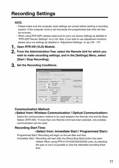
77
Recording Settings
NOTE:
- Please make sure the computer clock settings are correct before starting a recording session. If the computer clock is set incorrectly the programmed start time will also be incorrect.
- When using RTR-52Pt, please make sure to carry out sensor settings as detailed in "RTR-52Pt Sensor Settings" on p.124. Also, if you wish to use adjustment functions please carry out settings as detailed in "Adjustment Settings" on pp.125 - 127.
1. Open RTR-5W (VLD) Module.
2. From the Administration Tree, select the Remote Unit for which you wish to make recording settings, and in the [Settings] Menu, select [Start / Stop Recording].
3. Set the Recording Conditions.
Communication Method: <Select from: Wireless Communication / Optical Communication>
Select the communication method to be used between the Remote Unit and the Base Station (RTR-5W). *If more than one Remote Unit have been selected, only wireless communication can be used.
Recording Start Time: <Select from: Immediate Start / Programmed Start>
Programmed Start: Recording will begin on the set date and time.Immediate Start: Recording will start after the [Recording Start] button has been
clicked. When using RTR-51/51A/52/52A/53/53A units, by selecting the type of unit it is possible to view the estimated recording finish time.
78
Recording Interval: <Select from: 1,2,5,10,15,20,30 seconds, or 1,2,5,10,15,20,30,60 minutes>
Click the [ ] button to select an interval from the list.
Recording Mode: <Select from: Endless / One Time> Endless: Upon reaching capacity of 16,000 readings, the oldest data is overwritten
and recording continues. One-time : Upon reaching capacity of 16,000 readings, "FULL" will appear in the
LCD display and recording will automatically stop. (For RTR-53, the unit will become full at 8,000 readings in each channel.)
4. Click the [Start Recording] button to send the recording condition settings via the RTR-5W Station to the Remote Unit and complete the set-up.
NOTE:By starting a new recording session, all currently recorded data will be erased.
[Get Settings] Button Gather current recording condition settings from the selected Remote Unit. The gathering of current recording settings cannot be carried out on a multiple number of Remote Units.
[Recording Stop] ButtonPress to stop recording during a recording session.
79
Gathering Current Data
Gather and view current measurement readings from the selected Remote Unit(s) via wireless communication.
1. Open RTR-5W (VLD) Module.
2. From the Administration Tree, select the Remote Unit from which you wish to gather current data.
By holding down the <Shift> key or the <Ctrl> key and clicking on another Remote, it is possible to select a multiple number of Remote Units.
3. In the [Data] Menu, select [Gather Current Data]. * Also, by right clicking on the Remote Unit icon, a popup menu will appear where you
can select [Gather Current Data] to display the [Gathering Current Data] window.
The selected Remote is displayed.
[Gather]Button
4. Click the [Gather] button to start communication with the Remote Unit and the current data readings will be displayed.
Sequential Gathering Communication will occur at the set interval to intermittently gather and display current readings. As new current readings are gathered, the [Time] and [Ch1], [Ch2] data will be updated. (Normally only the most recent communication results will be shown.)
NOTE:- If this interval is short, battery life will be depleted quickly. - The shortest interval that can be entered will depend on the number of Remote Units for which
communication is carried out; it is not possible to enter a time interval that is less than the number of Remote Units x 30 seconds. The highest value the interval can be set to is 3,600 seconds.

80
Downloading Recorded Data
It is possible to download recorded data by two methods: "Wireless Communication" or "Optical Communication". The downloaded data will be saved both as an Encrypted Thermo Recorder File (.trc).
NOTE:- To open an Encrypted Thermo Recorder File, it is necessary to enter a valid User ID and
Password. For this reason, it is necessary to make sure to keep on record the User ID and Password that were used when the encrypted file was created. Without the User ID and Password, it is impossible to open the original Encrypted Thermo Recorder File.
- Make sure the clock settings are correct before starting a downloading session. If the computer clock is set incorrectly, the programmed start time will also be incorrect.
When using Wireless Communication
1. Open RTR-5W (VLD) Module.
2. From the Administration Tree, select the Remote Unit from which you wish to download data, and in the [Data] Menu, select [Down-
load Data].
The Selected Remote Unit Info
Specify the download mode
[Download]Button
[Specify the File Name]Button
3. Select the Download Mode.
4. If you wish to save the file by specifying the location, click the [Specify File Name] button and make Saving Location Settings.
5. Click the [Download] button to start downloading. If data from only one Remote Unit has been downloaded, a message will appear asking whether you wish to view the Graph or not.

81
[Cancel Downloading] ButtonUse this to stop a downloading session in progress. Note that if a downloading session is stopped while in progress, the results will NOT be saved to a file.
[Open Graph] ButtonOnce downloading has been completed, select the name of the Remote Unit from the list and click [Open Graph] to view the data in graph form. At this time, the encrypted Thermo Recorder File (.trc) will be decrypted into a Common Thermo Recorder Type File (.trx). Please assign a File Name for the decrypted Data File.
82
When using Optical Communication
1. Open RTR-5W (VLD) Module.
2. Place the Remote Unit from which you wish to download data face down on top of the RTR-5W.
3. From the Administration Tree, select the Location you will use for Optical Communication.
4. In the [Data] Menu, select [Download Data (Optical Communication)].
Specify the download mode
[Download]Button
[Specify...]Button
5. Click the [Specify] button to specify the file saving location. If only one Remote Unit has been selected, the default file name will appear when this window is opened.
6. Make settings for [Specify the Downloading Mode].
7. Click the [Download] button to start downloading. If you wish to continue downloading from other units, repeat the process as in steps 2 to 7. Once downloading has been completed, a message will appear asking whether you wish to view the Graph or not.
[Cancel Downloading] ButtonUse this to stop a downloading session in progress. Note that if a downloading session is stopped while in progress, the results will NOT be saved to a file.

83
Archive Viewer
All operations within each application which require authorization to carry out will be automatically recorded in the Operations History and saved in a History File in the same Folder into which RTR-5W VLD for Windows was installed.
Temperature / Humidity Graph (RTR-5W VLD) Operations History File "File Name (without extension)" _Hist.dat
[Upload Saved Print Settings] Operations History File "File Name (without extension)" _pri_Hist.dat
Operations History Files for other than Temperature / Humidity Graph (RTR-5W VLD) "File Name (without extension)" Logger_Hist.dat
One Achieve File can save up to 10,000 records. If the number of records exceeds 10,000, new records will be saved in ****_Hist_0001.dat. If Archive folders exceed another 10,000 records, new records will be saved in ****_Hist_0002.dat, then ****_Hist_0003.dat, etc...
NOTE:If an archive file is damaged, or if an error occurs while writing to an archive file, the records will be saved as above. A damaged Archive File cannot be opened.
With the Archive Viewer it is possible to filter through various archival records by Task, User ID, and Operation Date, view those records and save the archived information on display in text file format. It is also possible to sort through the archived records by clicking on the Title for each Filter Column such as [Date/Time] or [Task].

84
Opening Archive File Open existing Archive Files.
1. In the [File] Menu, select [Open Archive File].
[Open]Button
Select a file to open
2. Select the archive file that wish to open and click [Open] to view in the Archive Viewer.
Save as Text File Save the archived information that is being displayed in the Archive Viewer in text file format.
1. In the [File] Menu, click [Save as Text File].
[Save]Button
Assign a Location
Select the Text File Type
2. Specify the [Location] and enter a [File Name].
3. Designate the File Type and save by clicking the [Save] button.

85
Filter Here it is possible to make settings for the conditions of the recorded info you wish to view in the Archive Viewer.
1. In the [Operations] Menu, click on [Filters].
[OK]Button
[Apply]Button
Task By clicking the [ ] button, a list of applications will appear from which you can select which application you wish to view.
Functions By clicking the [ ] button, a list of operations will appear from which you can select which operation you wish to view.
User IDBy clicking the [ ] button, a list of all registered User IDs will appear from which you can select which User ID you wish to view.
Start / ExitClick the [ ] button and make desired settings for the range.
2. After selecting the desired conditions, click the [Apply] button or the [OK] button and the Archive Viewer will use the selected conditions to display the records.
[Apply] ButtonAfter applying the filter settings, the dialog window will remain open.
[OK] ButtonAfter clicking [OK], the dialog window will close.

86
Clock Format Use this to change the format in which time is displayed in the Archive Viewer.
1. In the [View] Menu, move the mouse to [Open Archive File] and various time display formats will appear.
2. By clicking the desired format, the setting will be completed.
Status Bar: [View] MenuUse this to Hide / View in the Status Bar in the Archive Viewer.
Revise: [View] Menu Revises the Archive Viewer display.
87
Auto-Download Settings
Make settings here to automatically download data from the selected Remote Units at the specified time.
1. Open RTR-5W (VLD) Module.
2. Select the Remote Unit(s) you wish to make settings for, and in the [Registration/Administration] Menu, click on [Remote Unit Properties].
* By right clicking on the selected Remote Unit icon(s), a popup menu will appear where you can select [Remote Unit Properties] to display the same window.
3. Select to download [Every day at a fixed time] or [Fixed Interval] and make the appropriate settings.
Make settings for the interval between downloads
Make settings for the time of download
Every day at fixed time (24 hour clock) Carry out the downloading of data automatically at a set time every day.
Fixed IntervalCarry out the downloading of recorded data automatically at a set interval of time. (Make setting for 10 days or less)

88
4. Assign a Data Storage Folder by clicking on the [Browse] button and selecting the desired folder.
Assign a Data Storage Folder.
*Using "RTR-5W VLD for Windows" with Windows Vista or Windows 7 Note that when using the Windows Vista or Windows 7 OS the "Virtual Store"
function will redirect files from the default folder into which the program was installed to separate folders under [Program Files] for each user, as shown below: [C:\User\(AccountName)\AppData\Local\VirtualStore\Program Files\(Application)].
(EX: If login was carried out using the account name "myname" and "RTR-5W VLD for
Windows" is the application being run, the saving location will appear in the application window as: [C:\Program Files\RTR-5W VLD for Windows\data] but due to the "Virtual Store" function the actual saving location will be [C:\User\myname\AppData\Local\VirtualStore\Program Files\RTR-5W VLD for Windows\data].
If the login was carried out from [Run as Administrator], the file will be saved to the folder as it appears in the application window.
5. Click the [OK] button to finish the setting process.
NOTE:- Make sure that RTR-5W (VLD) Module is open when a programmed Auto-Download is
scheduled to occur. - If, another type of communication, such as a warning monitoring, occurs at the scheduled
downloading time and downloading is not possible, downloading will begin upon the ending of the other communication.
- Depending on radio wave conditions, data downloading may at times be impossible. Please check in the downloading log for important data.
- If the recording mode is set for One Time and the logger becomes full, you may be downloading the same data over and over again.
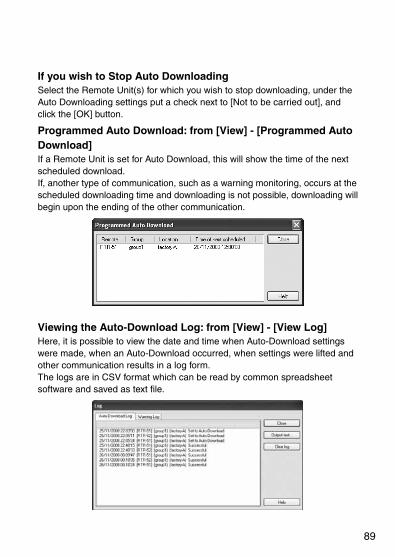
89
If you wish to Stop Auto DownloadingSelect the Remote Unit(s) for which you wish to stop downloading, under the Auto Downloading settings put a check next to [Not to be carried out], and click the [OK] button.
Programmed Auto Download: from [View] - [Programmed Auto Download]If a Remote Unit is set for Auto Download, this will show the time of the next scheduled download. If, another type of communication, such as a warning monitoring, occurs at the scheduled downloading time and downloading is not possible, downloading will begin upon the ending of the other communication.
Viewing the Auto-Download Log: from [View] - [View Log] Here, it is possible to view the date and time when Auto-Download settings were made, when an Auto-Download occurred, when settings were lifted and other communication results in a log form. The logs are in CSV format which can be read by common spreadsheet software and saved as text file.

90
Notes for Using Auto-Download Function
About the Auto-Download Function and Windows Automatic Update Windows can be set to use the Windows Automatic Update function. This will auto-
matically periodically download and install patches, updates and important software
repair programs in order to keep your computer up-to-date. If the default setting
[Install Updates Automatically] is being used for Windows Update, depending on the
downloaded program, Windows may automatically restart after downloading has been
completed.
Control Panel Windows Update Display(all displays are taken from Vista)
To solve this problem please take steps such as the following:
1. Place a shortcut for "RTR-5W VLD for Windows" in the [Startup] Folder of the [Start] Menu.
By doing this, "RTR-5W VLD for Windows" will be started when Windows is restarted, and if the programmed time for the Auto Download has passed, a message will be displayed asking whether or not you wish to run the Auto Download, thereby putting the application in a waiting status for an entry from the user.

91
2. In the "Change Settings" display, we do not recommend that the setting be for other than "Install updates automatically (recom-mended)".
Therefore we suggest the following to disable the Auto-restart of your computer system after an installation has occurred.
Windows Update - Change Settings Display
* If in this display, the setting [Install updates automatically (recommended)] has been selected, installation and Auto-restart may occur without any confirmation necessary from the user.
3. After making settings for Windows Update in the "Group Policy Object Editor", select to not automatically restart the system after installation.
Group Policy Object Editor Display
1. Open the "Group Policy Object Editor". In the [Start] Menu under [Run...] enter [gpedit.msc] to open.
2. Under [Computer Configuration] select [Administrative Templates] - [Windows Components] - [Windows Update] to open the Windows Update Tree.

92
3. Upon selecting “Windows Update” from the tree, a pane will appear to the right for settings, double click on [No auto-restart for scheduled Automatic Updates installed] to open the settings window.
4. Select [Enable] and click the [OK] button or the [Apply] button. By doing this the Auto-restart of the system will be stopped from occurring.
5. After finishing the settings downloads and the installation of repair programs from Windows Update will occur automatically, but while being logged on, Auto-restart of the system will not occur. A message, as shown below, will appear asking for the user to restart the computer.

93
Warning Monitoring
By setting upper and lower limits, warning monitoring can be carried out for each Remote Unit at each Location.
1. Open Network Settings Utility (VLD) and click on the [Detailed Network Settings] tab. Then click the [Change Settings] button to display a window where settings changes can be made.
2. Make settings for the "DNS Server Address" in [DNS Settings] and for the "SMTP Server Name" in [Warning Mail].
Enter SMTP settings
Enter the DNS server address
3. Open RTR-5W (VLD) Module.
4. Select the Remote Unit(s) you wish to make settings for, and in the [Registration/Administration] Menu click on [Remote Unit Properties].
* By right clicking on the selected Remote Unit icon(s), a popup menu will appear where you can select [Remote Unit Properties] to display the same window.
5. Check [When operating the warning function, monitor this Remote Unit], and enter values for the upper and lower limits.
[Settings]Button
Enter Upper and Lower Limit Settings

94
6. Click the [OK] button to finish the setting process.
7. In the [Settings] Menu, click on [Start/Stop Warning]. * By right clicking on the selected Remote Unit icon(s), a popup menu will appear
where you can select [Start/Stop Warning] to display the same window.
[A sender address]
[Warning Monitoring]
[notification address]
[Notification Settings]
8. Make the desired settings.
Warning MonitoringIf you wish to carry out the monitoring of warnings, place a check next the [Warning ON] and make monitoring interval settings. Enter an amount of time between 10 minutes and 1440 minutes. If this interval is short, battery life will be depleted quickly.
Notification Address Set the recipient address(es) for the Warning Mail. If the check is removed, the warning mail will not be sent to that address.
Sender AddressThis will be only used in the mail display to show where a warning report mail has been sent from.
NOTE:Please enter a valid e-mail address via which the sending and receiving of e-mail can be performed. It should be noted that if you assign an invalid or an imaginary Sender Address, the mail may not reach the intended party.
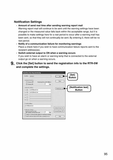
95
Notification Settings- Amount of send rest time after sending warning report mail
Warning report mail will continue to be sent until the warning settings have been changed or the measured value falls back within the acceptable range, but it is possible to make settings here for a rest period to occur after a warning mail has been sent, so that they will not continually be sent. By entering 0, there will be no rest period.
- Notify of a communication failure for monitoring warnings Place a check here if you wish to have communication failure reports sent to the recipient address(es).
- Switch external output to ON when a warning occurs If you wish to have an alarm or warning lamp that is connected to the external output go on when a warning occurs.
9. Click the [Set] button to send the registration info to the RTR-5W and complete the settings.
[Notification test]Button
[Set]Button

96
[Notification Test] Button- Use this to send a test mail from the RTR-5W to the notification address and
confirm that the warning notification settings are correct. - A notification test is successful if a notification test mail reaches the notification
address. If it does not reach the set address, please check the SMTP server, Notification Address, and Sender Address settings.
- If you are sending mail via the Internet, it is necessary to first make sure that your network is properly connected to the Internet and you can send mail outside of your network.
- Depending on your operating environment, it may take some time before the mail is received. (Especially if the address is a cell phone address.)
Before carrying out a notification test, it is necessary to make settings for the following: - There must be a check next to Warning ON and proper entries must be made for
[Notification Address] and [Sender Address]. - In Network Settings Utility (VLD), the SMTP server (mail server) must be assigned
properly. (If you have questions, see the information provided by your provider). - Please enter a valid e-mail address via which the sending and receiving of e-mail
can be performed in the [Sender Address] column. It should be noted that if you assign an invalid or an imaginary Sender Address, the mail may not reach the intended party.
Viewing the Warning Log: from [View] - [View Log] In the warning log will appear all warning occurrences. Due to timing problems, there may be instances when a warning cannot be stored into the computer. For details, see the Help for RTR-5W (VLD) Module. The logs are in CSV format which can be read by common spreadsheet software and saved as text file.

97
Remote Unit Battery Life Warning Settings
Make settings here to send a notification of a Remote Unit's low battery power via e-mail from the RTR-5W.
1. Open RTR-5W (VLD) Module.
2. Click [Remote Unit Battery Life Warning Settings] in the [Settings] Menu.
3. Place a check next to [Send Warning E-mail from RTR-5W] and enter the Send Time, Sender Address and Recipient Address.
Also, if you wish to use the same settings for all locations, put a check next to [Make same settings for all locations].
Check
4. Click the [OK] button to send the settings to the RTR-5W and complete the settings.
5. Click the [Transmission Test] button to test if a mail can be sent.
If warnings exist, send mail at this time Make setting for the time of sending a battery life warning mail.
Sender AddressEnter the address from which a battery life warning mail will be sent.
NOTE:Please enter a valid e-mail address via which the sending and receiving of e-mail can be performed. It should be noted that if you assign an invalid or an imaginary Sender Address, the mail may not reach the intended party.
Recipient AddressEnter the address to which a battery life warning mail will be sent. Up to 3 e-mail addresses can be assigned. Please set an address to which it is possible to send a mail from the RTR-5W environment.

98
Mail Settings for Downloaded Data
NOTE:When new Remote Units have been added or Remote Units have been erased causing a change in the Group / Remote Unit configuration of a Location, please make settings again and send the new settings to the Location.
1. Open RTR-5W (VLD) Module.
2. Specify the location, and in the [Settings] Menu click on [Mail Settings for Download].
3. Place a check next to [Send mail containing the downloaded data from this location] and make [Location Settings].
Location Settings
Check
Recorded Data Format (attachment) Select the format for the attached data file. - TRX: These are T&D formats which can be directly opened with T&D Graph
applications. (Note that a data file sent from the RTR-5W will not be encrypted. )
- Binary Format (for open format): This data file format is for public access. By using this format, users can create their own applications.
Subject Name (Title) Enter the title of the e-mail. Up to 16 characters can be entered.
Sender AddressThis is the address from which a mail containing the downloaded data will be sent.
NOTE:Please enter a valid e-mail address via which the sending and receiving of e-mail can be performed. It should be noted that if you assign an invalid or an imaginary Sender Address, the mail may not reach the intended party.
Recipient Address The data file will be sent as a mail attachment to the mail address entered here. Please set the notification address to one to which it is possible to send mail from the RTR-5W environment.

99
4. Make [Remote Unit Settings].
[Remote Settings]
Check
From the list of Remote Units, select the desired unit(s)
[OK]Button
[View these Settings]Button
[Gather Schedule]Button
[Transmission Test] Button
Select a Remote Unit or Units for which you wish to make settings from the list and check [Send mail containing data from selected Remote]. Select either [Send at Fixed Time Every Day] or [Send at Fixed Interval] and then set the number of hours for downloading data in the [Download data for this number of hours].
5. After the settings have been completed, click [View these Settings]. If you wish to make settings for other Remote Units, repeat the process as in steps 4 and 5.
6. Click the [OK] button to send the settings to the RTR-5W and complete the settings.
7. Click the [Transmission Test] button to test if a mail can be sent.
[Gather Schedule] Button This will retrieve download schedule info from the RTR-5W and display the time of the next scheduled download.
NOTE:New settings made here will not be transmitted to the RTR-5W and will not become activated until the [OK] button has been clicked.

100
101
Temperature / Humidity Graph (RTR-5W VLD)
This section describes how to save, print and view downloaded data in graph form: or by changing the viewing method the data can be viewed in table or list form.

102
Operating the Temperature / Humidity Graph (RTR-5W VLD)
How to OpenFrom the list of programs in the Window's Start Menu, click on [RTR-5W VLD for Windows] - [Temperature Humidity Graph (RTR-5W VLD)].
Using HelpFor details about how to use the software, please see the explanations in the Software Help Menu.
* In the Menu Bar, click [Help] - [Search by Topic], then click on one of the tabs [Contents], [Index], or [Search] to search for the topic or term you are unsure about or have questions about.
[Contents]By clicking on one of the topics listed, you can find detailed information for that subject.
[Index] By selecting a Keyword in the Keyword list, and clicking the [Display] button at the bottom, a detailed explanation will appear.
[Search] Enter the keyword you wish to search for and click the [List Topics] button. All topics that contain the keyword will be displayed. By selecting a topic and clicking the [Display] button at the bottom, a detailed explanation will appear.
* By clicking the [Help] button in a dialog box, an explanation for that dialog box will appear.
* In the Graph Window, by clicking on the [?] in the toolbar, you can have short explanations appear the next time you click on a menu, an icon, or anything in the main window.
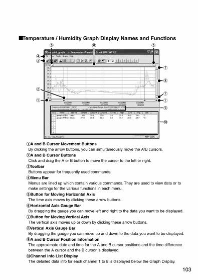
103
Temperature / Humidity Graph Display Names and Functions
A and B Cursor Movement Buttons By clicking the arrow buttons, you can simultaneously move the A/B cursors.
A and B Cursor Buttons Click and drag the A or B button to move the cursor to the left or right.
ToolbarButtons appear for frequently used commands.
Menu BarMenus are lined up which contain various commands. They are used to view data or to make settings for the various functions in each menu.
Button for Moving Horizontal Axis The time axis moves by clicking these arrow buttons.
Horizontal Axis Gauge Bar By dragging the gauge you can move left and right to the data you want to be displayed.
Button for Moving Vertical Axis The vertical axis moves up or down by clicking these arrow buttons.
Vertical Axis Gauge Bar By dragging the gauge you can move up and down to the data you want to be displayed.
A and B Cursor Position Information The approximate date and time for the A and B cursor positions and the time difference between the A cursor and the B cursor is displayed.
Channel Info List Display The detailed data info for each channel 1 to 8 is displayed below the Graph Display.

104
Zoom in Using the Mouse With the left button drag the mouse to outline the area you want to zoom in on.
Menu Display Using the Mouse By right clicking on the graph, the Menu will be displayed.
Display Graph Using Drag and DropIt is possible to view data in graph form by dragging a recorded data file and dropping it onto the Graph.
NOTE:- In Windows Vista and Windows 7, a lower-level User cannot use drag and drop to open a File if
a higher-level User opened the Graph program. For example, if the Graph program was opened using [Run as Administrator] and then using
Explorer a file is dropped into the Graph window, the file will not appear if Explorer was opened using any other User than Administrator.

105
Data List Display Part Names and Functions This is a list of the data that was displayed in graph form. (From the [View] Menu)
[Date/Time] ButtonBy clicking this button, you can shift the display between the recorded date and the amount of elapsed time since recording started.
Recorded Date Display
[Date/Time]Button
Highest Value: RED, Lowest Value: BLUE, Average Value: PINK Scroll Bar: By dragging it up and down you can move to the data you want.
Elapsed Time Display
Menu Display Using the MouseBy right clicking on the graph, the Menu will be displayed.
106
Making Changes to the Graph Display
Change Colors of Data Display Area: [View] Menu You can change the letters used in the data list display for each channel between monochrome and channel color.
Selected Channel Graph Display ON/OFF: [View] Menu You can choose to view only the selected channels in the Graph.
1. By moving the mouse to [Selected Channels ON / OFF], the channel numbers are displayed.
2. Click the channel number to remove or place a check mark. Only those channels with a check mark next to the number will be displayed in the Graph.
* The same operation can be done by clicking on the channel number icons in the Toolbar.
Enlarged
Check

107
Set High, Low, Average Calculation Range: [Tools] Menu
1. Enter a calculation range in the [New Calculation Range].- By clicking the [Entire Graph] button, the dates and times for the entire
graph will be displayed.- If in the graph display, you place the A cursor at the position for the
beginning of the calculation range and the B cursor at the end of the range, those dates and times will appear as the new range in the [Set High, Low, Average Calculation Range] Display when it is opened.
[OK]Button
Enter a calculation range
[Entire Graph]Button
2. Click the [OK] button to complete the settings.
108
Edit Recording Conditions: [Tools] Menu It is possible to make corrections to channel names and to recording start date and times.
1. By clicking the Number button of the Channel you wish to edit, the [Name] and [Started Date / Time] in the "Edit Items" area will show info for that Channel Number.
- Name: Up to 32 letters can be entered.
- Started Date / Time: Started Date/Time: The month, day, year, hour, minute and second can be changed.
[OK]Button
[Restore]Button
Channel Number
Edit Items
2. After making changes, click the [OK] button. Then a window will appear asking you to [Enter the reason for the editing of data.]
The entered reason will be saved in the Operations History File and can be viewed in the Archive Viewer [Details] column.
3. After entering the reason, click the [OK] button to finish the editing. If you wish to continue to change other channels, repeat the process as in 1.
* The [Restore] button is only effective while making changes. After clicking the [OK] button the settings cannot be restored to the original settings.

109
Re-order Channel Data: [Tools] Menu You can re-order the data during graph display. There are two methods to use when re-ordering channels: "Re-order by Dragging a Channel Number" and "Specify the Channel Numbers to be Moved".
Re-order by Dragging a Channel Number
1. Click the channel number you wish to move.
2. While holding down the mouse button, drag the channel number you wish to move to the newly desired channel number position and drop it.
[OK]Button
[Restore]Button
Drag the channel number you wish to move to the desired position
3. After clicking the [OK] button, a window will appear asking you to [Enter the reason for the editing of data.]
The entered reason will be saved in the Operations History File and can be viewed in the Archive Viewer [Details] column.
4. After entering the reason, click the [OK] button to finish the re-ordering. * The [Restore] button is only effective while making changes. After clicking the [OK]
button the settings cannot be restored to the original settings.

110
Specify the Channel Numbers to be Moved
1. Specify the channels to be moved. From: (original position) To: (desired position)
[OK]Button
[Restore]Button
If you wish to move Ch.3 to the Ch.7 position, set as such: From Ch.3, To Ch.7
[Re-order]Button
2. After clicking the [Re-order] button and the [OK] button, a window will appear asking you to [Enter the reason for the editing of data.]
The entered reason will be saved in the Operations History File and can be viewed in the Archive Viewer [Details] column.
3. After entering the reason, click the [OK] button to finish the re-ordering. * The [Restore] button is only effective while making changes. After clicking the [OK]
button the settings cannot be restored to the original settings.
111
Erase Selected Channel Data: [Tools] Menu
1. Place a check on the channel number you wish to erase.
Check
[OK]Button
2. After clicking the [OK] button, a window will appear asking you to [Enter the reason for the erasing of data.]
The entered reason will be saved in the Operations History File and can be viewed in the Archive Viewer [Details] column.
3. After entering the reason, click the [OK] button to finish the erasing of the data.
* The [Restore] button is only effective while making changes. After clicking the [OK] button the settings cannot be restored to the original settings.
Shift Unit (ºC /ºF) : [Tools] MenuBy clicking on [Shift Unit (ºC /ºF)], you can automatically change the temperature unit scale in the graph display and in the channel info list.

112
Change Graph Colors: [Tools] Menu
1. Click the channel number of which you wish to change the color to view the color selection samples.
You can change the colors of the channel name, graph background, the scale lines, the enlarged box area, and the AB cursors.
Color sample
[OK]Button
[Default]Button
[Line Width]Button
2. Choose the color you want and click the [OK] button.
3. After confirming the color, by clicking the [OK] button the change will be completed.
* By clicking the [Default] button, you will return to the color settings when the software was opened.
Graph Line Width Settings It is possible to change the width of the data lines and the scale lines.
[OK]Button
[Default] Button
1. Click on the [ ] button to change the width of the graph / scale lines. - Every time you click on [ ], the numerical value gets larger. - Every time you click on [ ], the numerical value gets smaller.
2. Click the [OK] button to complete the changes. * By clicking the [Default] button, you will return to the color settings when the software
was opened.

113
Copy Display to Clipboard: [Tools] Menu By clicking [Copy Display to Clipboard], you can copy the currently displayed window to the clipboard and make use of the graph by pasting to other software.

114
Operating the Graph Display: [Graph] Menu
Return to Original Size Clicking here will return the graph to its original size.
Zoom In / Zoom Out Zoom in or out one step at a time.
Move Cursor Right / Move Cursor Left Simultaneously move the AB Cursors to the right or left.
Move Graph Right / Move Graph Left Move the Graph Display to the right or left one step at a time.
Move Graph Up / Move Graph Down Move the Graph Display up or down one step at a time.
Vertical Axis SettingsSet the vertical axis scale range.
1. Check either [Auto] or [Manual]. - Auto: The vertical axis will automatically be changed according to the
values of the data.
- Manual: It is possible to set the upper and lower values of the vertical axis scale.
[OK]Button
[Default ] Button
If using manual, enter the vertical scale range.
2. Click the [OK] button to complete the settings. * By clicking the [Default] button, you will return to the settings when the software was
opened.

115
Printing the Graph
Print the graph in the current display. * If you wish to change the size of the Graph, change the size of the window before
printing.
Print Graph: [File] Menu At the top right and left of the graph of the printed Graph, two dates and times will be printed. Also, a mark showing that it was printed with Temperature / Humidity Graph (VLD) will be printed.
Current Date and Time When you upload saved print settings to print a graph, the date and time when the printing settings were saved will appear. Date and Time that the Graph was first printed Mark showing that it was printed with Temperature / Humidity Graph (VLD)
Print Preview
Saving of Printing Settings Upon printing a Graph, a message will appear asking [Do you wish to save the Print Settings?]
When you use [Upload Saved Print Settings] you can print a graph of recorded data with
the same scale and positioning info as when it was saved. (File will have extension ".trp")

116
Upload Saved Print Settings: [File] Menu A graph that has already been printed will appear as it was saved and can be reprinted with exactly the same printing settings.
NOTE:- If a Graph is already currently being viewed, it will be deleted and a new Graph will be created. - When using [Upload Saved Print Settings] to view a Graph, functions other than the actual
printing operation and the Help Menu will become unusable.
1. In the [File] Menu, select [Upload Saved Print Settings].
2. Select the File you wish to upload, and click the [Open] button to view it in the Graph display.
[Open]Button
Select a file to open

117
Saving Recorded Data
If you have edited any data after viewing it with the Graph display, we suggest that you save it as you see necessary.
3 Ways to Save Files...[File] Menu
Overwrite All Data Save any changes to file without changing File Name and Saving Location. The same operation can be carried out from [Save] in the Toolbar.
Save All Data as...Save with a new File Name.
Save Displayed Data as...Save only that data in the current display. This is handy when you wish to save only the desired data.
EX: [Save All Data as...]
1. Click [Save All Data as...] in the [File] Menu.
Enter a File Name
Assign a Location
[Save] Button
2. Specify the Location and enter a [File Name].
3. Click [Save] to complete the saving process.
NOTE:To open an Encrypted Thermo Recorder File, it is necessary to enter a valid User ID and Password. Without the User ID and Password that were used at the time of creation, it is impossible to open the original Encrypted Thermo Recorder File.

118
Creating Text File
By saving the recorded data as text file, you can create a file type that can be read by common spreadsheet software.
1. Click [Save Data in Text File] in the [File] Menu.
2. Select the [Delimiters] and [Range to be saved], and click [OK]. Comma, Tab, Space, and Semi-colon are codes used by common spreadsheet software, such as Excel and Lotus, when reading Text File to divide cells.
[OK]Button
Select the Delimiter Select the range to be saved
3. Designate the location to which the file should be saved and click [Save] to create and save the data as a Text File document.
The extension for the created file will be ".txt".
[Save] Button
Assign a Location
Enter a File Name
* NOTE: Text File cannot be read into Temperature / Humidity Graph (RTR-5W VLD).
119
Opening a Saved File
To display a previously saved file in Graph form, specify the file name to open it.
Ex: Opening an Encrypted Thermo Recorder File
NOTE:To open an Encrypted Thermo Recorder File, it is necessary to enter a valid User ID and Password. Enter the User ID and Password that were used when the original file was created. Without the User ID and Password that were used at the time of creation, it is impossible to open the original Encrypted Thermo Recorder File.
1. Click [Open] in the [File] Menu of the Graph Display.
2. Select the Encrypted Thermo Recorder File you wish to view, and click the [Open] button to view it.
[Open]Button
Select a data file to open
If it is a Common Type File, the info for the selected file will be displayed
If you have selected a Common Thermo Recorder Type File

120
3. To view the file in Graph display, enter a File Name for the decrypted file and click [Save].
[Save]Button
* Using “RTR-5W VLD for Windows” with Windows Vista or Win-dows 7Note that, when using Windows Vista or Windows 7, if, as a normal User, “RTR-5W VLD for Windows” was installed into the default folder [Program Files] the “Virtual Store” function may redirect and save files into separate folders for each User Account, as shown below:[C:\User\(AccountName)\AppData\Local\VirtualStore\Program Files\(Application)].(EX: If login was carried out using the account name “myname” and “RTR-5W VLD for Windows” is the application being run, the saving location will appear in the application window as: [C:\Program Files\RTR-5W VLD for Windows\data] but due to the “Virtual Store” function the actual saving location will be [C:\User\myname\AppData\Local\VirtualStore\Program Files\RTR-5W VLD for Windows\data]. If the login was carried out from [Run as Administrator], the file will be saved to the folder as it appears in the application window.

121
If another User opens an Encrypted File
1. Enter a File Name for the decrypted file and click the [Save] button. Then a message will appear.
[OK]Button
2. By clicking the [OK] button, a window will appear asking you to enter the same "User ID" and "Password" as the original Login
when the file was created.
3. After entering these, by clicking the [OK] button, the Graph will be displayed.

122

123
Other Operations
- RTR-52Pt Sensor Settings- Adjustment Settings- How to use the RTR-5W Web Viewer- Monitoring Current Readings (accessing via browser)- Viewing Graph (accessing via browser)- Viewing Current Readings via Mobile Phone
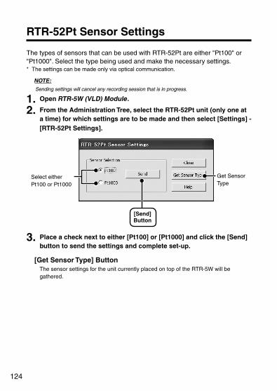
124
RTR-52Pt Sensor Settings
The types of sensors that can be used with RTR-52Pt are either "Pt100" or "Pt1000". Select the type being used and make the necessary settings. * The settings can be made only via optical communication.
NOTE:Sending settings will cancel any recording session that is in progress.
1. Open RTR-5W (VLD) Module.
2. From the Administration Tree, select the RTR-52Pt unit (only one at a time) for which settings are to be made and then select [Settings] - [RTR-52Pt Settings].
[Send]Button
Select either Pt100 or Pt1000
Get Sensor Type
3. Place a check next to either [Pt100] or [Pt1000] and click the [Send] button to send the settings and complete set-up.
[Get Sensor Type] Button The sensor settings for the unit currently placed on top of the RTR-5W will be gathered.

125
Adjustment Settings (Optical Communication)
Adjustment is a function used to make adjustments to correct inaccuracies found in measured values when compared to a standard or reference measurement. By setting an adjustment equation beforehand, adjustment function will automatically calculate to record and display the post-adjusted measurement. There are two methods of adjustment: adjusting by one point or adjusting by two points. Adjustment for differences will be based upon the following simple equation Y=aX+b. (X equals the measured value and Y equals the value after adjustment.)
NOTE:- The adjustment function can be used only with the RTR-51A, 52A, 52Pt, 53A. Note that the
RTR-51, 52, 53 do not contain this function.- The settings can be made only via optical communication. - When you are carrying out adjustments and formulating equations please take care with the
settings and take personal responsibility for the process.
1 Point Adjustment, 2 Point AdjustmentAfter selecting the method of adjustment; enter the actual measurement before adjustment and the desired measurement after adjustment. From the entered values, an adjustment equation will be formulated.
NOTE:- When adjusting at 2 points, it is important to make sure the points are not too close to each
other. The probability of measurement errors will increase in other ranges outside of the two points. If possible select two points apart from one another (we suggest at least 10 degrees) to measure and make the necessary adjustments.
- Do not enter values that would result in the slope being 0.
1. Open RTR-5W (VLD) Module.
2. From the Administration Tree, select the Remote Unit (only one at a time) for which settings are to be made and place it face down on top of the RTR-5W.
3. In the [Settings] Menu, select [Adjustment Settings (Optical Communication)].
Select either [1 Point Adjustment] or [2 Point Adjustment]. Then enter the actual pre-adjusted value(s) in the [Current Readings] column and the post-adjusted reference value(s) in the [Post-adjusted Reading] column.

126
Check one of the methods
[Send Settings]Button
[Initioalize] Button
4. After entering the settings, click the [Send Settings] button to send the adjustment equation to the selected Data Logger.
Once they have been successfully transmitted, the setting procedure will have been completed.
[Rough Guidelines for Adjustment]
1 Point Adjustment: Use when measuring in a range of 20ºC.This adjustment method changes only the offset (b) where the slope (a) is considered 1. For example, the RTR-51A is measuring 10ºC, but the standard says the actual measurement should be 10.2ºC. Enter 10 in the Current Reading box and 10.2 in the Post - adjusted Reading boxThe conversion equation will be "Y=X+0.2" and for all measurements an adjustment to the offset of +0.2 will be made.

127
2 Point Adjustment: Use when measuring in a wide range.The adjustment equation will be calculated from two points: the slope (a) and the offset (b). For example, the RTR-51A reads 0ºC when the standard thermometer reads 0.4ºC, and reads 10ºC when the standard says the true measurement is 10.2ºC. In this case the slope (a) is 10.2-0.4 /100 = 0.98.The offset is 0.4, so the conversion equation becomes "Y=0.98X+0.4".The range of the slope is 0<a<=2. Entries are valid to one decimal point, but after calculation up to four digits are valid for the slope and offset.
[Initialize] Button Clears any previous adjustment equation(s) from the selected Data Logger and initializes the device.
NOTE:By making new adjustment settings to an already adjusted device without first clicking the [Initialize] button, the new adjustment equation will be used to further adjust the previously adjusted result. (Ex: if the first time the offset is set at 0.1 and the second time at 0.2, then the offset will be 0.3 from the original measured data.) If you carry out new adjustment settings without first initializing the device, it is easy to see that the difference will increase dramatically. When carrying out adjustment to the slope (2 point adjustment), these differences will be especially large if the entered values are outside of the temp/humidity range. When you are carrying out adjustments and formulating equations please take care with the settings and take personal responsibility for the process.

128
How to use the RTR-5W Web Viewer
Opening the RTR-5W Web Viewer
1. Open Internet Explorer. * If you wish to use the Internet, make sure that the power for the router and computer
are on so as to enable connection to the Internet. * Make settings to enable both Java applets and Java script.
2. In the address area, enter the address of the RTR-5W logger you wish to view.
Enter address
3. By pressing the <Enter> key, the RTR-5W Web Viewer will appear.
If the Viewer does not appear
1. Make sure that the address you entered is correct.
2. Check to make sure that the IP address and subnet mask are set correctly and if necessary redo the [Network Initialization] settings.
3. Make sure that in [Location (RTR-5W) Properties] there is a check next to [Make access possible from a browser].
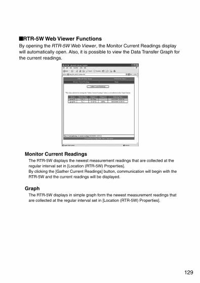
129
RTR-5W Web Viewer Functions By opening the RTR-5W Web Viewer, the Monitor Current Readings display will automatically open. Also, it is possible to view the Data Transfer Graph for the current readings.
Monitor Current Readings The RTR-5W displays the newest measurement readings that are collected at the regular interval set in [Location (RTR-5W) Properties]. By clicking the [Gather Current Readings] button, communication will begin with the RTR-5W and the current readings will be displayed.
GraphThe RTR-5W displays in simple graph form the newest measurement readings that are collected at the regular interval set in [Location (RTR-5W) Properties].

130
Monitoring Current Readings (accessing via browser)
View the current readings for all the Remote Units registered to a Location (RTR-5W).
1. Open RTR-5W (VLD) Module and make Data Gathering Interval settings.
* For details about how to make settings, see "Browser Display Settings" (p.58) of "Remote Unit Registration".
2. Open the Web Viewer for the RTR-5W of which you wish to view the current readings.
* See p.128 for details about the display.
[Gather Current Readings]Button
3. The [Monitor Current Readings] display will automatically open.
4. Click the [Gather Current Readings] button to get the most recent info.
* If the registration info is incorrect, go to RTR-5W (VLD) Module [Settings] Menu - [Send Group/Remote Info] and send the correct registration info.
To view graphs in your browser, it is necessary to have Java Runtime Environment (JRE) installed on your computer.
If JRE is not already installed, please download and install it from the Sun Microsystems Website [http://www.java.com/en/].
NOTE:The installation of JRE is completely the responsibility of the user.
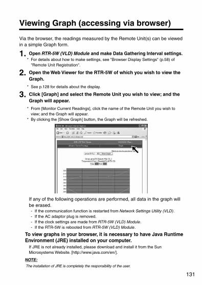
131
Viewing Graph (accessing via browser)
Via the browser, the readings measured by the Remote Unit(s) can be viewed in a simple Graph form.
1. Open RTR-5W (VLD) Module and make Data Gathering Interval settings. * For details about how to make settings, see "Browser Display Settings" (p.58) of
"Remote Unit Registration".
2. Open the Web Viewer for the RTR-5W of which you wish to view the Graph.
* See p.128 for details about the display.
3. Click [Graph] and select the Remote Unit you wish to view; and the Graph will appear.
* From [Monitor Current Readings], click the name of the Remote Unit you wish to view; and the Graph will appear.
* By clicking the [Show Graph] button, the Graph will be refreshed.
If any of the following operations are performed, all data in the graph will be erased. - If the communication function is restarted from Network Settings Utility (VLD). - If the AC adaptor plug is removed. - If the clock settings are made from RTR-5W (VLD) Module. - If the RTR-5W is rebooted from RTR-5W (VLD) Module.
To view graphs in your browser, it is necessary to have Java Runtime Environment (JRE) installed on your computer.
If JRE is not already installed, please download and install it from the Sun Microsystems Website. [http://www.java.com/en/].
NOTE:The installation of JRE is completely the responsibility of the user.
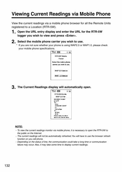
132
Viewing Current Readings via Mobile Phone
View the current readings via a mobile phone browser for all the Remote Units registered to a Location (RTR-5W).
1. Open the URL entry display and enter the URL for the RTR-5W logger you wish to view and press <Enter>.
2. Select the mobile phone carrier you wish to use. * If you are not sure whether your phone is using WAP2.0 or WAP1.0, please check
your mobile phone specifications.
3. The Current Readings display will automatically open.
NOTE:- To view the current readings monitor via mobile phone, it is necessary to open the RTR-5W to
the public on the Internet. - The current readings will not be automatically refreshed. You will have to use the browser refresh
function on you cell phone. - Depending on the status of line, the communication could take a long time or communication
failure may occur. Also, it may take some time to display current readings.

133
Others
- Checking and Making Changes to Computer Network Settings - If USB Device Driver Installation Fails - Re-installing- Troubleshooting- FAQ's- Specifications- Options
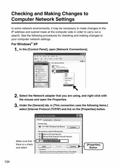
134
Checking and Making Changes to Computer Network Settings
In some network environments, it may be necessary to make changes to the IP address and subnet mask at the computer side in order to carry out a search. See the following procedures for checking and making changes to your computer network settings.
For Windows® XP
1. In the [Control Panel], open [Network Connections].
2. Select the Network adapter that you are using, and right click with the mouse and open the Properties.
3. Under the [General] tab, in [This connection uses the following items:] select [Internet Protocol (TCP/IP) and lick on the [Properties] button.
[Properties]Button
Make sure that there is a check and select

135
4. In the [Internet Protocol (TCP/IP) Properties] window, under [Use the following IP address:] make sure that the IP address and Subnet mask are appropriate for your network.
* If the setting [Obtain an IP Address automatically] has been selected, the IP address area will be blank.
Check to make sure that the [IP address] and [Subnet mask] are correct
5. In order to return the settings back to the original ones, make sure to write down the current settings for [IP address], [Subnet mask], [Default gateway], [Preferred DNS server] and [Alternate DNS server].
6. Enter "192.168.1.1" as the IP Address and "255.255.255.0" as the Subnet mask.
IP address: 192.168.1.1 / Subnet mask: 255.255.255.0
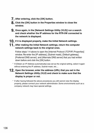
136
7. After entering, click the [OK] button.
8. Click the [OK] button in the Properties window to close the window.
9. Once again, in the [Network Settings Utility (VLD)] run a search and check whether the IP address for the RTR-5W connected to the network is displayed.
10. If it is displayed properly, make the Initial Network settings.
11. After making the Initial Network settings, return the computer network settings back to the original ones.
Follow steps 1-4 above to open the [Internet Protocol (TCP/IP) Properties] window. Re-enter the [IP address], [Subnet mask], [Default gateway], [Preferred DNS server], and [Alternate DNS server] that you had written down before and click the [OK] button.
* If [Obtain an IP Address automatically] was set as the original setting, select it again without entering the IP address, Subnet mask, etc....
12. Open the browser, enter the address (URL) that you set in the Network Settings Utility (VLD) and check to make sure that the display is proper or not.
* If after having followed the above procedures you still cannot view the display properly, please connect your network administrator. Some environments such as a company network may have special settings.
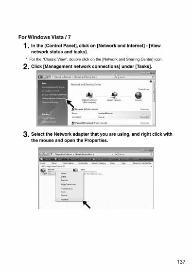
137
For Windows Vista / 7
1. In the [Control Panel], click on [Network and Internet] - [View network status and tasks].
* For the "Classic View", double click on the [Network and Sharing Center] icon.
2. Click [Management network connections] under [Tasks].
3. Select the Network adapter that you are using, and right click with the mouse and open the Properties.

138
4. Select [Internet Protocol Version 4 (TCP/IPv4)] and click on the [Properties] button.
Make sure that there is a check and select [Properties]
Button
* Make sure that there is a check next to [Internet Protocol Version 4 (TCP/IPv4)]. If there is no check, the [Properties] button cannot be clicked.
5. In the [Internet Protocol Version 4 (TCP/IPv4) Properties] window, under [Use the following IP address:] make sure that the IP address and Subnet mask are appropriate for your network.
* If the setting [Obtain an IP Address automatically] has been selected, the IP address area will be blank.
Check to make sure that [IP address] and [Subnet mask] are correct
6. In order to return the settings back to the original ones make sure to write down the current settings for [IP address], [Subnet mask], [Default gateway], [Preferred DNS server], and [Alternate DNS server].

139
7. Enter "192.168.1.1" as the IP address and "255.255.255.0" as the Subnet mask.
IP address: 192.168.1.1 / Subnet mask: 255.255.255.0
8. After entering, click the [OK] button.
9. Click the [OK] button in the Properties window to close the window.
10. Once again, in the [Network Settings Utility (VLD)] run a search and check whether the IP address for the RTR-5W connected to the network is displayed.
11. If it is displayed properly, make the Initial Network settings.
12. After making the Initial Network settings, return the computer network settings back to the original ones.
Follow steps 1-4 above to open the [Internet Protocol Version 4 (TCP/IPv4) Properties] window. Re-enter the [IP address], [Subnet mask], [Default gateway], [Preferred DNS server], and [Alternate DNS server] that you had written down before and click the [OK] button.
* If [Obtain an IP Address automatically] was set as the original setting, select it again without entering the IP address, Subnet mask, etc....
13. Open the browser, enter the address (URL) that you set in the Network Settings Utility (VLD) and check to make sure that the display is proper or not.
* If after having followed the above procedures you still cannot view the display properly, please connect your network administrator. Some environments such as a company network may have special settings.

140
If USB Device Driver Installation Fails
If, during USB device driver installation, some trouble occurs that results in a failure to install properly, the following display will appear in the Device Manager.
Ex. of display (Windows® XP)
For Windows® XP Please re-install the USB Device Driver.
1. In the [Control Panel], open [System].
2. In the [System Properties] window, click the [Hardware] tab, and then click the [Device Manager] button in the [Device Manager] area.

141
3. In the Device Manager Window, right click on [USB Device] under [Other Devices] and then click on [Properties] to display the [USB Device Properties] window.
4. In the [USB Device Properties] window, click on the [Reinstall Driver] button to display the Hardware Installation Wizard. Follow the directions to install.

142
For Windows® Vista / 7After installing the software RTR-5W VLD for Windows, very occasionally communication will not work despite connecting an RTR-50 unit with a USB communication cable to your computer. In this case, please carry out the following procedures.
1. In the [Control Panel], open [System] or [System and Maintenance].
2. Open the [Device Manager] window. In the [System and Maintenance] window, click [Device Manager]. For the "Classic View", double click on the [Device Manager] icon.
3. In the [Device Manager] window, select the unknown device with the [?] or [!] icon and right click on it to show the Menu.
4. Click [Uninstall] in the Menu to uninstall the device temporarily.
5. After rebooting the computer, check whether the USB device driver has been properly installed by connecting an RTR-50 unit with a USB communication cable to the computer.
For how to check, see p.65 "Checking the USB Device Driver Installation".
* It is not necessary to re-install the software.
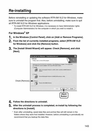
143
Re-installing
Before reinstalling or updating the software RTR-5W VLD for Windows, make sure to uninstall the program first. Also, before uninstalling, make sure to quit all RTR-5W VLD for Windows applications.
* To install RTR-5W VLD for Windows, it is necessary to have Administrator rights (Computer Administrator) for the computer in which you wish to install it.
For Windows® XP
1. In the Windows [Control Panel], click on [Add or Remove Programs].
2. From the list of currently installed programs, select [RTR-5W VLD for Windows] and click the [Remove] button.
3. The [Install Shield Wizard] will appear. Check [Remove], and click [Next].
[Next]Button
Check [Remove]
4. Follow the directions to uninstall.
5. After the uninstall process is completed, re-install by following the directions to [Install].
* Even after uninstalling, saved data files and archive files will still remain in the folders where they were first installed. However, before uninstalling or periodically we recommend that you backup the data files.

144
For Windows® Vista / 7
1. In the [Control Panel], click [Programs] - [Uninstall a program].
2. From the list of currently installed programs, select [RTR-5W VLD for Windows] and click the [Uninstall] button.
3. After a message will appear asking you if it is OK to remove the application, click the [Yes] button to complete the uninstall process.
[Yes]Button
* Even after uninstalling, saved data files and archive files will still remain in the folders where they were first installed. However, before uninstalling or periodically we recommend that you backup the data files.

145
Troubleshooting
RTR-5W VLD for Windows
Q.1 The date and the time of the recorded data are different from the actual date and time. Why?
A The RTR-5 Series Data Logger has no internal clock. When you set up a programmed recording start or when you download data, the date and time that are shown are taken form your computer's clock. Therefore, if your computer's clock is not correct, it will affect the recorded data.
Q.2 I forgot or lost the User ID and/or Password used to open an Encrypted Thermo Recorder File. Is there any way I can open the encrypted file?
A No. Without the User ID and Password that were used when the original file was created, it is impossible to open the original Encrypted Thermo Recorder File.
Q.3 In the File Save window, the timeout does not occur when no operations are performed, why not?
A All Windows common dialog windows (File dialogs, Print dialogs, Color dialogs, etc...) and Print Preview are designed so as not to be affected by the timeout function.
Q.4 Is it possible to save an encrypted file with a new name and open it?
A Yes, that is possible. Note that to open an encrypted file, it is necessary to enter the User ID and Password that that were used at the time of creation.
Q.5 I uploaded file using the [Upload Saved Printing Settings] into a Temperature / Humidity Graph (VLD), but now I can't carry out any operations in the Graph, why not?
A The only reason to use upload data using [Upload Saved Printing Settings] is to reprint the exact same Graph as it was printed before. Hence, it has been designed so that no changes can be made to the Graph. To lift the restriction against carrying out any operations, either go to the [File] Menu and click [Open] to open the temperature / humidity data in a new Graph or reboot the Temperature / Humidity Graph (VLD) application.
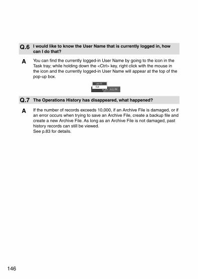
146
Q.6 I would like to know the User Name that is currently logged in, how can I do that?
A You can find the currently logged-in User Name by going to the icon in the Task tray; while holding down the <Ctrl> key, right click with the mouse in the icon and the currently logged-in User Name will appear at the top of the pop-up box.
Q.7 The Operations History has disappeared, what happened?
A If the number of records exceeds 10,000, if an Archive File is damaged, or if an error occurs when trying to save an Archive File, create a backup file and create a new Archive File. As long as an Archive File is not damaged, past history records can still be viewed. See p.83 for details.
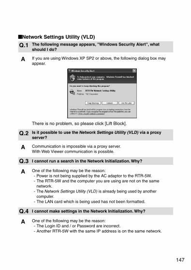
147
Network Settings Utility (VLD)
Q.1 The following message appears, "Windows Security Alert", what should I do?
A If you are using Windows XP SP2 or above, the following dialog box may appear.
There is no problem, so please click [Lift Block].
Q.2 Is it possible to use the Network Settings Utility (VLD) via a proxy server?
A Communication is impossible via a proxy server. With Web Viewer communication is possible.
Q.3 I cannot run a search in the Network Initialization. Why?
A One of the following may be the reason:- Power is not being supplied by the AC adaptor to the RTR-5W.- The RTR-5W and the computer you are using are not on the same
network.- The Network Settings Utility (VLD) is already being used by another
computer.- The LAN card which is being used has not been formatted.
Q.4 I cannot make settings in the Network Initialization. Why?
A One of the following may be the reason:- The Login ID and / or Password are incorrect.- Another RTR-5W with the same IP address is on the same network.
148
Q.5 Why does the message "Communication Error (Connection Error)" appear?
A The network is probably not properly connected. One of the following may be the reason:- One of the following is incorrect: IP address or Domain, Login ID,
Password, or Port Number.- The network is not properly connected (the LAN cable is broken, the Hub
is damaged, a mistake occurred in setting up the router, etc...) - In the [Menu] - [ Communication Time Settings] try slowing the
communication time.
Q.6 Because of some other "Communication Error", communication cannot occur. Why?
A One of the following may be the reason:- The IP Block setting in the Network Settings Utility (VLD) is ON and
communication can occur with only specific PC's.- A warning report mail or test mail may be in process. Also, if a sending
error occurs, processing takes time.Please wait for at lease one minute before trying again. If after several attempts a communication error continues to occur, turn OFF the RTR-5W and reboot.
Q.7 Which has priority, a wireless LAN or a wired LAN?
A If a wireless LAN card is inserted, the wireless LAN will have priority. Because of this, if the wireless LAN settings are incorrect and a wired LAN is connected, communication will not take place via the wired LAN and hence communication will not occur.
Q.8 I forgot the password, what should I do?
A First, return the settings to the factory default settings and then redo the settings.
Q.9 Is it possible to hide the IP address history and settings history?
A If you wish to hide the History, in the [Menu], select [Login History] and click to [OFF]. Please note that a history will remain viewable from when before it was disabled. To erase a history, please click on [Clear Login History] in the Menu.

149
FAQ's
Q&A about RTR-5W
Q.1 RTR-5W units use an AC adaptor, what happens when there is power shortage?
A - During a power shortage, communication via LAN cannot occur. - If SNTP server settings have not been made, the clock will reset. - The data files for transfer stored in the RTR-5W will be erased. - All warning occurrence logs stored in the RTR-5W will be erased.
Q.2 Can I connect directly to my computer with the LAN cable that comes with the logger?
A The LAN cable supplied is a straight LAN cable and in some cases it cannot be used to connect directly to your computer. Therefore, we suggest using a cross LAN cable in order to connect an RTR-5W directly to your computer. Please purchase a cross LAN cable at your local computer supply store.
Q.3 Does the RTR-5W have a clock and calendar?
A The RTR-5W has an internal clock (calendar) built into it. If the internal clock settings for the RTR-5W are not set correctly, the date and time in the RTR-5W Web Viewer's current readings monitor and the time of warnings will also be incorrect. Make sure to set correctly before using.
NOTE: If you make clock settings manually, the clock will lose its settings upon removal of the AC adapter or after restarting the system.
Q.4 Is it possible to connect the RTR-5W to the network by using the LAN cable that connects the computer to the LAN network?
A Inserting the wireless LAN card that connects the computer to the network into the RTR-5W will physically connect the RTR-5W to the network, but without making the necessary settings such as IP address, the RTR-5W cannot be active in the network and hence is not really connected. After having inserted the LAN cable, make sure to go to [Network Settings Utility VLD] to make the necessary IP address and Subnet mask settings.

150
Q.5 Is it possible to connect the RTR-5W to the wireless LAN by removing the wireless LAN card from my computer and inserting it into the RTR-5W?
A It is necessary to make Wireless LAN settings. In [Network Settings Utility VLD], under [Detailed Network Settings] make changes to the [Wireless LAN Settings]. After that, turn OFF the RTR-5W power, then insert the card and turn the power back ON.
Q.6 I want to use a wireless LAN, which products should I use?
A Please use only those CF type Wireless LAN cards that have been proven to be compatible and are suggested for use. For information and updates concerning which wireless LAN cards can be used, please contact your local T&D dealer or representative.
Q.7 Which has priority, a wireless LAN or a wired LAN?
A If the Wireless LAN is connected properly and all settings are correct, the Wireless LAN will have priority.
Q.8 I want to have a mail sent when a warning occurs, how can I do this?
A To use the warning mail function, it is necessary to have an SMTP server. If you have an Internet connection, use the mail server of your Internet service provider or some other means to access a mail sever. If you have a mail server on your company LAN, there may be specific instructions and settings for sending mail. Please ask the network administrator at your company for details.

151
Q&A about Web Server Functions
Q.1 Are the RTR-5W Base Stations web servers?
A The RTR-5W stations have web server functionality built into them. This function allows for the provision or serving up of temperature and humidity data, current readings and graphs.
Q.2 What is a Web Server? What is a client?
A In a computer network, the computer that acts as a provider of services to various users is called a server and the computers which request these services from the server are referred to as clients. Most communication service is made up of exchanges between servers and clients. In the case of RTR-5W, the RTR-5W provides functions and information so it is a server and the computer, which reads this information or functions, is the client. For example, the storage of websites and the making public of these are done by the "Web Server" and the sending and receiving of e-mail is preformed by the "Mail Server".
Q&A about Viewing the Website
Q.1 Can I use an RTR-5W without connecting it to a network?
A If the RTR-5W is not connected to a network, the downloading of recorded data, the display of current readings, recording settings and all other types of settings cannot be carried out.
Q.2 What must I do to view current RTR-5W readings on my cell phone?
A To view the current readings of an RTR-5W it is necessary to connect the RTR-5W to the Internet. If the RTR-5W is connected to the Internet, it is possible to view the current readings via your cell phone by entering the same URL in your cell phone browser's URL bar as you do when viewing via your computer.
152
Q&A about Networks
Q.1 What is a Network?
A A network is a system in which a group of computers are connected by cable (copper wire, optical fiber, etc.), infrared ray, radio waves or other means in order to share and exchange information. There are basically two types of computer networks.- LAN (Local Area Network)
A Local Area Network or LAN consists of a group or network of computers in a limited range.
- WAN (Wide Area Network) A Wide Area Network or WAN is a network of computers that are connected over long distance. The Internet is an example of a WAN that has connected a multiple number of networks.
Q.2 What is an IP address?
A In a network, in order to distinguish your computer from another it is necessary to assign a number; this number is called an IP address. When you connect to an outside network such as the Internet, the IP address that is used is referred to as a "Global IP address". In a Local Area Network, the IP address that is used is called a "Private IP address".
An IP address is divided into 4 blocks of numbers separated by periods, such as "192.168.15.10". The assigned numbers can use the digits 0-255 with private IP addresses usually beginning with numbers such as [192.168.]. (However, the number "255." is not usually used. )This number is absolutely necessary to enable participation in a network, so it is necessary to set the IP address to a number that suits your network environment.
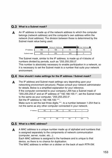
153
Q.3 What is a Subnet mask?
A An IP address is made up of the network address to which the computer belongs (network address) and the computer's own address within the network (host address). The division between these is determined by the Subnet mask value being used.
The Subnet mask, similar to the IP address, is made up of 4 blocks of numbers divided by periods, such as "255.255.255.0". This number is absolutely necessary to enable participation in a network, so it is necessary to set the Subnet mask to a number that suits your network environment.
Q.4 How should I make settings for the IP address / Subnet mask?
A The IP address and Subnet mask settings vary depending upon your networking environment (structure). Please consult your network administrator for details. Below is a simplified explanation for your reference. If the computer connected to your company LAN has a Subnet mask of "255.255.255.0" and an IP address of "192.168.100.1", set the Subnet mask to the same as your computer, "255.255.255.0". Set the IP address to 192.168.100.***. Make sure to set the last three digits,***, to a number between 1-254 that is not the same as any other computer connected in your network.
Q.5 What is a MAC address?
A A MAC address is a unique number made up of alphabet and numbers that is assigned separately to the components of network communication (computer, server, router, etc...). Each MAC address is assigned to the hardware and is unique to that device, so there is no chance for duplication. The MAC address is written on a sticker on the back of each RTR-5W.

154
Q.6 What is a port number?
A When using TCP/IP communication with a LAN cable or via a phone line, port numbers are assigned to distinguish one application from another.Port numbers can be assigned from 0 to 65535. The numbers 0 to 1023 are already reserved to communication services and are referred to as "Well Known Port Numbers". "Well Known Port Numbers" are: HTTP communication at 80 / FTP communication at 20 and 21 / SMTP communication (sending mail) at 25 / POP3 communication (receiving mail) at 110. In order for communication to work properly, these port numbers must be set correctly.
Q.7 What is a gateway?
A A gateway is a term used to refer to a device or software that is used to link networks with different standards. For example, a gateway is needed when connecting a cell phone to the Internet or in any case where you wish to connect two devices that are completely different. Gateway carries with it the meaning of "entrance and exit" and a router may also be referred to with this term. When making gateway settings, it is necessary to make IP address settings for the device that will act as a gateway.
Q.8 What is a URL?
A A URL is an address that is written in a way so that it is easy for the DNS function to determine on which server the IP address is located. This address begins with "http://" and is followed by such things as domain names, server names, port numbers, file names and other such info.
For example, if the IP address that is assigned to "www.tandd.com" is "61.197.203.107", by entering "http://61.197.203.107/product/product/rtr5w/index.php" in the browser, the same page will appear as when you enter "http://www.tandd.com/product/product/rtr5w/index.php".
* The DNS or Domain Name Server helps to switch difficult to understand IP address of just numbers, such as "61.197.203.107" into easy to grasp names such as "www.tandd.com" and helps connect to the desired server.

155
Q&A about the Internet
Q.1 What is an IP address?
A Usually, when you connect to the Internet, the provider with which you have contracted service automatically assigns an IP address which may be different each time you connect, or may change after a certain length of time. With this type of changing IP address, it is more difficult for outsiders to illegally enter your computer.
On the other hand, when using your computer or an RTR-5W unit as a server, it would be necessary to enter a different IP address as the URL each time you wish to access it. In such a case, it would be necessary to find out the current IP address each time you wished to access and this would be totally inconvenient.
To help solve this problem, there is something called a fixed IP address service that your provider can offer. With a fixed IP address, you will be assigned a special unique IP address. Some providers may give you a fixed IP address from the beginning of service, but with most providers it is necessary to sign up for this special service.
Q.2 How do you get a fixed IP address?
A A fixed IP address is a service offered by your Internet provider. For details about how to receive a fixed IP address, contact the Internet provider with which you are connected.
Q.3 How should I set up a fixed IP address?
A If you are using only one RTR-5W connected to one router, then the fixed IP address should not be set for the RTR-5W, but for the router. If you are using a multiple number of RTR-5W connected to one router, the RTR-5W will use FTP and HTTP so, please set a fixed IP address for each RTR-5W unit.
Because it is impossible, when using normal ADSL or FTTH lines, to directly connect the RTR-5W to the Internet line, it is necessary to place a router between the logger and the ADSL (FTTH) modem. When using a router, the fixed Internet IP address should be assigned to the router and all access to the RTR-5W from outside should go through the router. In this case, the router will have two IP addresses: an external IP address for the Internet and an internal IP address for the company or household LAN.

156
Q.4 I want to use a URL without a fixed IP address, how can I do that?
A If you wish to access an RTR-5W by URL but without a fixed IP address, it is possible to use a dynamic DNS. The DNS or Domain Name Server helps to switch difficult to understand IP address of just numbers, such as "61.197.203.107" into easy to grasp names such as "www.tandd.com" and helps connect to the desired server.
The DNS usually changes names to fixed IP addresses. But, if for some reason you cannot use a fixed IP address or for security reasons you wish not to use a fixed IP address, there is a type of DNS called a dynamic DNS, which can handle ever-changing IP addresses.
For example, the starting IP address is "210.0.0.1" and the URL associated with it is "http://www.rtr5w.com". The IP address "210.0.0.1" is of the changing type that is periodically reassigned by the provider. This IP address assigned by the provider changes periodically and after a certain period of time, the assigned IP address is changed to, for example, "210.0.0.2". Normally, at this point the DNS would not associate the URL with the IP address and access would be made impossible, but because the dynamic DNS tracks the IP address, you can still access the desired server using the same URL (this example: http://www.rtr5w.com.)
There are many types of dynamic DNS plans and services available, please contact your local provider for more details.
Q.5 Can I use the Warning Mail function without getting or using a fixed IP address?
A If it is possible for you to connect to the Internet by using a dynamic DNS, theoretically it is possible to send mail without having or using a fixed IP address. That is presuming it is possible to successfully send data via your provider's mail sever or your company's mail server. Fundamentally, if you are able to access your company mail server or connect to the Internet it should be possible to send mail.

157
Q.6 Is it possible to connect to the Internet without a fixed IP address nor a URL?
A Yes, it is possible to connect without using a URL or having a fixed IP address, but because the IP address that will be assigned by the provider will be constantly changing, the access will be varied and will not go smoothly. For example, the IP address that you used successfully one hour before may no longer work and access will be made impossible. Further, you will have no way of verifying the new IP address. We strongly suggest using either a fixed IP address or a dynamic DNS.
Q.7 If I connect the RTR-5W to the Internet, is it not possible that another person could read my data or change my settings?
A Yes, as long as you are connected to the Internet, the unit could well be the target of unwanted access. And, as long as you are open on the Internet, it is possible that a third party could view the RTR-5W current readings or recorded data, or even, make changes to your settings.
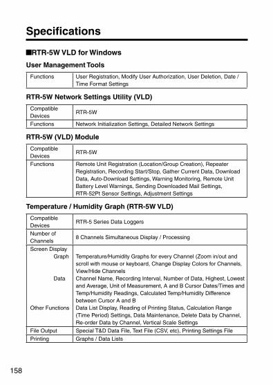
158
Specifications
RTR-5W VLD for Windows
User Management Tools
Functions User Registration, Modify User Authorization, User Deletion, Date / Time Format Settings
RTR-5W Network Settings Utility (VLD)
Compatible Devices
RTR-5W
Functions Network Initialization Settings, Detailed Network Settings
RTR-5W (VLD) Module
Compatible Devices
RTR-5W
Functions Remote Unit Registration (Location/Group Creation), Repeater Registration, Recording Start/Stop, Gather Current Data, Download Data, Auto-Download Settings, Warning Monitoring, Remote Unit Battery Level Warnings, Sending Downloaded Mail Settings, RTR-52Pt Sensor Settings, Adjustment Settings
Temperature / Humidity Graph (RTR-5W VLD)
Compatible Devices
RTR-5 Series Data Loggers
Number of Channels
8 Channels Simultaneous Display / Processing
Screen DisplayGraph
Data
Other Functions
Temperature/Humidity Graphs for every Channel (Zoom in/out and scroll with mouse or keyboard, Change Display Colors for Channels, View/Hide Channels Channel Name, Recording Interval, Number of Data, Highest, Lowest and Average, Unit of Measurement, A and B Cursor Dates/Times and Temp/Humidity Readings, Calculated Temp/Humidity Difference between Cursor A and B Data List Display, Reading of Printing Status, Calculation Range (Time Period) Settings, Data Maintenance, Delete Data by Channel, Re-order Data by Channel, Vertical Scale Settings
File Output Special T&D Data File, Text File (CSV, etc), Printing Settings File
Printing Graphs / Data Lists
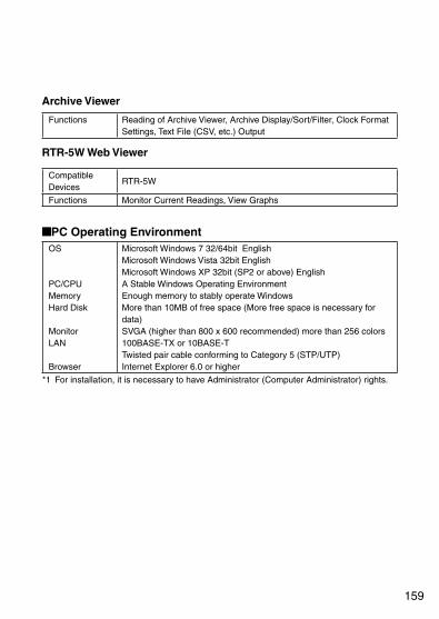
159
Archive Viewer
Functions Reading of Archive Viewer, Archive Display/Sort/Filter, Clock Format Settings, Text File (CSV, etc.) Output
RTR-5W Web Viewer
Compatible Devices
RTR-5W
Functions Monitor Current Readings, View Graphs
PC Operating Environment OS
PC/CPUMemoryHard Disk Monitor LAN
Browser
Microsoft Windows 7 32/64bit EnglishMicrosoft Windows Vista 32bit EnglishMicrosoft Windows XP 32bit (SP2 or above) EnglishA Stable Windows Operating EnvironmentEnough memory to stably operate Windows More than 10MB of free space (More free space is necessary for data) SVGA (higher than 800 x 600 recommended) more than 256 colors 100BASE-TX or 10BASE-T Twisted pair cable conforming to Category 5 (STP/UTP) Internet Explorer 6.0 or higher
*1 For installation, it is necessary to have Administrator (Computer Administrator) rights.

160
Web Wing WL RTR-5WCompatible Devices
RTR-51/51A, RTR-52/52A, RTR-52Pt, RTR-53/53A
Operational Status Display
LED Lamp Display (Power ON / Wireless Communication in Progress / Warning Occurrence)
Power Specific AC Adaptor
Communication Method
Wired LAN: 100 BASE-TX / 10 BASE-T (RJ45 Connector) Wireless LAN: IEEE802.11b (Commercial CF Wireless LAN Card)*1
Communication Speed
Special Short Range Wireless: 2000 readings per minute / Optical Communication: 2400bps
Communication Time
When downloading data from RTR-5 Series Data Logger with RTR-5W via wireless communication, 1 unit of full data takes about 420 seconds
External Output (Warning Output)
When operating the warning function Voltage when OFF: less than AC/DC 50V Current when ON: less than 0.1A / Resistance when ON: MAX 35
Dimensions / Weight of Main Unit
H83 W102 D28 mm (excluding protrusions) / About 137g
Operating Environment
Temperature: 0 to 50ºC / Humidity: 20 to 80%RH (without condensation)
Accessories included in package
AC Adaptor AD-0607 x 1 / LAN Cable LN-20W x 1 Software Set / Introductory Guide and Warranty x 1
*1 For information and updates concerning which wireless LAN cards can be used please see our Website.

161
Options
AC adaptor (for RTR-5W)AD-0607 AC adaptorAC 100 to 240VCable Length : 1.85 m
Wall Attachment Unit (for RTR-5W)TR-5WK1 Wall Attachment Kit Contents: Double-sided Adhesive Tape x 1
Screws x 2
Materials : Polycarbonate
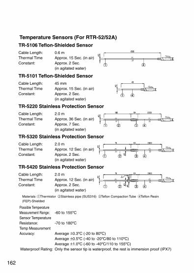
162
Temperature Sensors (For RTR-52/52A)TR-5106 Teflon-Shielded SensorCable Length:Thermal TimeConstant:
0.6 mApprox. 15 Sec. (in air)Approx. 2 Sec. (in agitated water)
TR-5101 Teflon-Shielded SensorCable Length:Thermal TimeConstant:
45 mmApprox. 15 Sec. (in air)Approx. 2 Sec. (in agitated water)
TR-5220 Stainless Protection SensorCable Length:Thermal TimeConstant:
2.0 mApprox. 36 Sec. (in air)Approx. 7 Sec. (in agitated water)
TR-5320 Stainless Protection SensorCable Length:Thermal TimeConstant:
2.0 mApprox. 12 Sec. (in air)Approx. 2 Sec. (in agitated water)
TR-5420 Stainless Protection SensorCable Length:Thermal TimeConstant:
2.0 mApprox. 12 Sec. (in air)Approx. 2 Sec. (in agitated water)
Materials : Thermistor Stainless pipe (SUS316) Teflon Compaction Tube Teflon Resin (FEP)-Shielded
Possible Temperature Measurement Range: Sensor Temperature Resistance: Temp Measurement Accuracy:
Waterproof Rating:
-60 to 155ºC
-70 to 180ºC
Average 0.3ºC (-20 to 80ºC)Average 0.5ºC (-40 to -20ºC/80 to 110ºC)Average 1.0ºC (-60 to -40ºC/110 to 155ºC)Only the sensor tip is waterproof, the rest is immersion proof (IPX7)

163
TR-5530 Water Immersible SensorCable Length:Thermal TimeConstant:
3.0 m
Approx. 12 Sec. (in air)Approx. 2 Sec. (in agitated water)
Materials : Thermistor Teflon Resin (FEP)-Shielded Teflon Resin (FEP)-Mold
Possible Temperature Measurement Range: Sensor Temperature Resistance: Temp Measurement Accuracy:
Waterproof Rating:
-60 to 155ºC
-70 to 180ºC
Average 0.3ºC (-20 to 80ºC)Average 0.5ºC (-40 to -20ºC/80 to 110ºC)Average 1.0ºC (-60 to -40ºC/110 to 155ºC)Sensor and Cable are submersible (IPX8)
Temp / Humidity Sensor (For RTR-53/53A) unit: millimeters
TR-3310 Temp / Humidity SensorCable Length:Sensor Response Time:
1 mAbout 7 minutes (Time to reach the 90 % of total humidity)
Materials : Temperature/Humidity sensor Polypropylene resin Vinyl Coated Electrical Wire
Possible Temperature Measurement Range: Possible Humidity Measurement Range: Sensor Temperature Durability: Temp Measurement Accuracy: Humidity Measurement Accuracy: Service Life: Operational conditions:
0 to 50ºC
10 to 95%RH
-10 to 60ºC
Average 0.3ºC
5%RH (at 25ºC 50%RH)1 year (under normal operational conditions)Without dew condensation, water leakage or effect from corrosive gas or organic solvents.

164
Sensor Adaptor (For RTR-52Pt) unit: millimeters
RTR-05P1 Sensor AdaptorCable Length:OperationalTemperature:
1.0 m
-25 to 60ºC
Materials : Vinyl Chloride Vinyl Coated Electrical Wire
* Not Waterproof.
Sensor Extension Cables (For RTR-52/52A) unit: millimeters
TR-2C30 Sensor Extension CableCable Length:OperationalTemperature :Waterproof Rating :
3.0 m
-25 to 60ºCIPX4 Splash Resistant(for use in daily life)
Materials : Vinyl Coated Electrical Wire
NOTE:
Only one cable per sensor.When using the extension cable there will be a +0.3ºC at normal temperature and at -50ºC a gap of +0.5ºC may occur.

165
Power (For RTR-5/RVR-5) unit: millimeters
RTR-05A1 External Power AdaptorVoltage Input:Back-up Power:
Back-up Time:Charging Method:Operating Temperature:Waterproof Capacity:Weight:Kit Contents:
DC6V to DC13VNi-MH Battery (In case of power loss)4 days (*1)Trickle Charge0 to 60ºCNoneAbout 37g (without AC Adaptor)AC Adaptor (AD-0604) x 1Attachment hook x 1Rubber Packing x 1 (for back of main unit)Rubber Packing (small) x 1 (for AC Adaptor jack)Silica Gel Pack (drying agent) x 1Double-sided Adhesive Tape x 1 (for fastening Silica Gel)Screws x 2 (extras for fastening back of main unit)
RTR-05B1 Large Capacity Battery PackPower:Battery Life:
Waterproof Capacity:Operating Temperature:Weight:Kit Contents:
Lithium Battery x 1 (LS26500)About 2 years and 6 months (*1)(Monitoring at 1 minute interval = about 20 months)Splash proof-40 to 80ºC (*2)About 75g (including lithium battery)Attachment hook x 1Rubber Packing x 1 (for back of main unit)Silica Gel Pack (drying agent) x 1Double-sided Adhesive Tape x 1 (for fastening silica gel)Screws x 2 (extras for fastening back of main unit)
(*1) : Battery Life varies depending on measuring environment, recording interval, transmission frequency, and ambient temperature. Specifications and explanations used in this User's Manual are based on operations carried out with a new battery and are in no way a guarantee of your actual battery life.
(*2): Operating temperature depends on the specifications for the data logger being used. When using RTR-05B1, it is necessary to purchase Lithium Battery (LS26500). For details, contact your local representative or dealer.

166
Power (For TR-5/RTR-5/RVR-5)TR-00P1 Maintenance SetKit Contents: Rubber Packing x 1 (for back of main unit)
Silica Gel Pack (drying agent) x 1Double-sided Adhesive Tape x 1(for fastening silica gel)Screws x 2(extras for fastening back of main unit)
TR-11P2 Low-Temperature Battery SetKit Contents: Lithium Battery x 1 (LS14250)
Tube x 1Maintenance set x 1 (TR-00P1)

167
Wall Attachment (For TR-5/RTR-5/RVR-5) unit: millimeters
TR-05K3 Wall AttachmentCompatible Devices:Operating Temperature:Kit Contents:
RTR-5/RVR-52/TR-5-40ºC to 80ºCDouble-sided Adhesive Tape x 1Screws x 2
NOTE:If a strong shock occurs to the unit in environments under -30ºC, cracking may occur.
TR-05K3L Wall AttachmentCompatible Devices:
Operating Temperature:Kit Contents:
For use with Data LoggersRTR-5L / RVR-52AL orRTR-5 / RVR-52A in conjunction with RTR-05A1 Adaptor or RTR-05B1 Battery Pack-40ºC to 80ºCDouble-sided Adhesive Tape x 1Screws x 2
NOTE:If a strong shock occurs to the unit in environments under -30ºC, cracking may occur.
Materials : Polycarbonate

Shimadachi 817-1, Matsumoto, Nagano 390-0852 Japan
Tel: +81-263-40-0131 Fax: +81-263-40-3152
Office Hours : Monday to Friday 9:00-12:00/13:00-17:00
(GMT +9:00 Tokyo Time)
WebsiteWe have opened an English Website for your convenience. Here you can find information about our company, news, products, upcoming events, Software and User's Manuals downloads, as well as, other support. Please stop by and see what we have to offer.
http://www.tandd.com/
RTR-5W VLD for Windows User's Manual
© Copyright T&D Corporation. All rights reserved.