rule based control system for home automation based control system for home automation claudio tesei...
TRANSCRIPT
University of CamerinoSCHOOL OF SCIENCE AND TECHNOLOGY
Master Degree in Computer Science
Rule Based Control System for HomeAutomation
Author SupervisorsClaudio Tesei Leonardo MostardaMatr. 088967 Marta Larusdottir
Academic Year 2013/2014

2

RULE BASED CONTROL SYSTEMFOR HOME AUTOMATION
December 2014
Claudio TeseiMaster of Science in Computer Science

RULE BASED CONTROL SYSTEM FORHOME AUTOMATION
Claudio TeseiMaster of Science
Computer Science
December 2014
School of Computer Science
Reykjavík University
M.Sc. EXPERIMENTAL THESISISSN 1670-8539

Rule Based Control System for Home Automation
by
Claudio Tesei
Experimental thesis submitted to the School of Computer Scienceat Reykjavík University and at University of Camerino in partial fulfillment of
the requirements for the degree ofMaster of Science in Computer Science from Reykjavík University andMaster of Science in Computer Science from University of Camerino
December 2014
Experimental Thesis Committee:
Leonardo Mostarda, SupervisorAssociate Professor, University of Camerino
Marta Lárusdóttir, SupervisorAssitant professor, Reykjavìk University
Luca TeseiAssistant Professor, University of Camerino
Hannes VilhjálmssonAssociate professor, Reykjavìk University

CopyrightClaudio Tesei
December 2014


Rule Based Control System for Home Automation
Claudio Tesei
December 2014
AbstractThis thesis is part of the result of a larger and complex project that me andDavide Angelici collaborated on during the autumn 2014. Consequently, tohave a complete view of the project, it is necessary to read also the MSc the-sis of Davide Anglici. In this project we have created a prototype for a newproduct that makes home automation easier and low cost. Through an elab-orate business plan we touch points as the market, the innovative value, themarketing strategy and some calculation to explain our economical plan; atthe same time we introduce our innovative product composed by eight pack-ets of easy installation with the aim of making smarter some componentsinside the house. After having introduced a clear overview of the system, wewill describe the design phase, in which more details are given to addressthe reader towards the implementation. This thesis is focused on the CentralUnit (the main topic of this document), the software employed to developit and the technique used to write the program. At the end some considera-tions about the work made until now are discussed and what remains to bedeveloped to achieve a product ready for the market.


Dedicated to the addictions...


viii

ix
Contents
List of Figures xii
List of Tables xv
1 Introduction 11.1 Overview . . . . . . . . . . . . . . . . . . . . . . . . . . . . . . . . . . 11.2 Goal of the Master Project . . . . . . . . . . . . . . . . . . . . . . . . . 21.3 Contributions . . . . . . . . . . . . . . . . . . . . . . . . . . . . . . . . 2
2 Business Plan 52.1 Overview . . . . . . . . . . . . . . . . . . . . . . . . . . . . . . . . . . 5
2.1.1 The opportunity: home automation easy and low-cost . . . . . . . 52.1.2 The product . . . . . . . . . . . . . . . . . . . . . . . . . . . . . 52.1.3 The team . . . . . . . . . . . . . . . . . . . . . . . . . . . . . . 62.1.4 The business model . . . . . . . . . . . . . . . . . . . . . . . . . 62.1.5 Roadmap and economic projections . . . . . . . . . . . . . . . . 6
2.2 The market and the competitive environment . . . . . . . . . . . . . . . . 62.2.1 Home Automation: the smart home . . . . . . . . . . . . . . . . 62.2.2 The standards are numerous . . . . . . . . . . . . . . . . . . . . 72.2.3 A great opportunity . . . . . . . . . . . . . . . . . . . . . . . . . 72.2.4 The customer asks for simplicity and flexibility . . . . . . . . . . 92.2.5 Feedback is Important . . . . . . . . . . . . . . . . . . . . . . . 92.2.6 The market trend . . . . . . . . . . . . . . . . . . . . . . . . . . 122.2.7 How will develop the global market . . . . . . . . . . . . . . . . 122.2.8 The main players . . . . . . . . . . . . . . . . . . . . . . . . . . 14
2.3 The product, process or invention: the value proposition . . . . . . . . . 182.3.1 How has it started . . . . . . . . . . . . . . . . . . . . . . . . . . 182.3.2 The product . . . . . . . . . . . . . . . . . . . . . . . . . . . . . 192.3.3 Placing on the market . . . . . . . . . . . . . . . . . . . . . . . . 21

x
2.4 The marketing plan . . . . . . . . . . . . . . . . . . . . . . . . . . . . . 222.4.1 Product . . . . . . . . . . . . . . . . . . . . . . . . . . . . . . . 222.4.2 Price . . . . . . . . . . . . . . . . . . . . . . . . . . . . . . . . 242.4.3 Sales channels (Placement) . . . . . . . . . . . . . . . . . . . . . 252.4.4 Promotion . . . . . . . . . . . . . . . . . . . . . . . . . . . . . . 25
2.5 Operational Plan . . . . . . . . . . . . . . . . . . . . . . . . . . . . . . 262.5.1 Roadmap . . . . . . . . . . . . . . . . . . . . . . . . . . . . . . 262.5.2 Compliance of the system . . . . . . . . . . . . . . . . . . . . . 272.5.3 Make or buy? . . . . . . . . . . . . . . . . . . . . . . . . . . . 272.5.4 Operation characteristics . . . . . . . . . . . . . . . . . . . . . . 272.5.5 Technical Assistance . . . . . . . . . . . . . . . . . . . . . . . . 29
2.6 Organizational Structure . . . . . . . . . . . . . . . . . . . . . . . . . . 302.6.1 Value chain . . . . . . . . . . . . . . . . . . . . . . . . . . . . . 302.6.2 Organization chart of the company . . . . . . . . . . . . . . . . . 31
2.7 The economic and financial plan . . . . . . . . . . . . . . . . . . . . . . 32
3 Software Design 353.1 Purpose of the System Design Document . . . . . . . . . . . . . . . . . 353.2 General Overview . . . . . . . . . . . . . . . . . . . . . . . . . . . . . . 353.3 Design Considerations . . . . . . . . . . . . . . . . . . . . . . . . . . . 36
3.3.1 Goals and Guidelines . . . . . . . . . . . . . . . . . . . . . . . . 363.3.2 Development Methods . . . . . . . . . . . . . . . . . . . . . . . 363.3.3 Architectural Strategies . . . . . . . . . . . . . . . . . . . . . . . 37
3.4 Hardware Architecture Design . . . . . . . . . . . . . . . . . . . . . . . 373.4.1 Logical View . . . . . . . . . . . . . . . . . . . . . . . . . . . . 373.4.2 Hardware Architecture . . . . . . . . . . . . . . . . . . . . . . . 38
3.5 Software Architecture Design . . . . . . . . . . . . . . . . . . . . . . . . 423.5.1 Central Unit . . . . . . . . . . . . . . . . . . . . . . . . . . . . . 423.5.2 Packages . . . . . . . . . . . . . . . . . . . . . . . . . . . . . . 443.5.3 Mobile App . . . . . . . . . . . . . . . . . . . . . . . . . . . . . 443.5.4 Workstation . . . . . . . . . . . . . . . . . . . . . . . . . . . . . 44
3.6 Internal Communications Architecture Design . . . . . . . . . . . . . . . 443.6.1 Communications Hardware Architecture . . . . . . . . . . . . . 453.6.2 Communications Software Architecture . . . . . . . . . . . . . . 46
3.7 DB Design . . . . . . . . . . . . . . . . . . . . . . . . . . . . . . . . . 473.7.1 Central Unit Database . . . . . . . . . . . . . . . . . . . . . . . 473.7.2 Web Page Database . . . . . . . . . . . . . . . . . . . . . . . . . 49
3.8 User Machine-Readable Interface . . . . . . . . . . . . . . . . . . . . . 50

xi
3.8.1 Inputs . . . . . . . . . . . . . . . . . . . . . . . . . . . . . . . . 503.8.2 Outputs . . . . . . . . . . . . . . . . . . . . . . . . . . . . . . . 52
4 Central Unit Implementation 534.1 Architecture overview . . . . . . . . . . . . . . . . . . . . . . . . . . . . 534.2 Install the environment on the Raspberry Pi . . . . . . . . . . . . . . . . 54
4.2.1 The OS . . . . . . . . . . . . . . . . . . . . . . . . . . . . . . . 544.2.2 LAMP . . . . . . . . . . . . . . . . . . . . . . . . . . . . . . . 554.2.3 Java JDK . . . . . . . . . . . . . . . . . . . . . . . . . . . . . . 564.2.4 SPI . . . . . . . . . . . . . . . . . . . . . . . . . . . . . . . . . 56
5 Control Software 615.1 State of the Art . . . . . . . . . . . . . . . . . . . . . . . . . . . . . . . 615.2 Kaalisy Rules . . . . . . . . . . . . . . . . . . . . . . . . . . . . . . . . 635.3 The ECA language . . . . . . . . . . . . . . . . . . . . . . . . . . . . . 63
5.3.1 ANTLR . . . . . . . . . . . . . . . . . . . . . . . . . . . . . . . 635.3.2 Lexer and Parser . . . . . . . . . . . . . . . . . . . . . . . . . . 645.3.3 The Language in B.N.F. . . . . . . . . . . . . . . . . . . . . . . 65
5.4 Overview of the components and their requirements . . . . . . . . . . . . 675.5 Server Communicator . . . . . . . . . . . . . . . . . . . . . . . . . . . . 695.6 DataBase Communicator . . . . . . . . . . . . . . . . . . . . . . . . . . 695.7 Package Communicator . . . . . . . . . . . . . . . . . . . . . . . . . . . 70
5.7.1 Auto-installation . . . . . . . . . . . . . . . . . . . . . . . . . . 715.8 Kaalisy Rules Engine . . . . . . . . . . . . . . . . . . . . . . . . . . . . 72
5.8.1 Overview of the component . . . . . . . . . . . . . . . . . . . . 725.8.2 The semantic value . . . . . . . . . . . . . . . . . . . . . . . . . 75
6 Conclusion 796.1 Future work . . . . . . . . . . . . . . . . . . . . . . . . . . . . . . . . . 80
6.1.1 Improvements . . . . . . . . . . . . . . . . . . . . . . . . . . . . 806.1.2 Developing . . . . . . . . . . . . . . . . . . . . . . . . . . . . . 806.1.3 Testing . . . . . . . . . . . . . . . . . . . . . . . . . . . . . . . 81
6.2 Future Project . . . . . . . . . . . . . . . . . . . . . . . . . . . . . . . . 816.2.1 The reason . . . . . . . . . . . . . . . . . . . . . . . . . . . . . 816.2.2 The way . . . . . . . . . . . . . . . . . . . . . . . . . . . . . . . 826.2.3 Reflection . . . . . . . . . . . . . . . . . . . . . . . . . . . . . . 82
Appendices 85

xii

xiii
List of Figures
2.1 The smart home [?] . . . . . . . . . . . . . . . . . . . . . . . . . . . . . 72.2 Do you have an home automation system? . . . . . . . . . . . . . . . . . 102.3 Would you like to have it? . . . . . . . . . . . . . . . . . . . . . . . . . 112.4 Why you do not have it? . . . . . . . . . . . . . . . . . . . . . . . . . . 112.5 Home automation system in Italy 2005-2013[?] . . . . . . . . . . . . . . 132.6 Expected development for the global market of home automation[?] . . . 132.7 "UnicamSolar" developed for the University of Camerino (2013) . . . . . 192.8 Logic view of "Kaalisy Domotics" system . . . . . . . . . . . . . . . . . 192.9 Dwelling with a Kaalisy Domotics system . . . . . . . . . . . . . . . . . 212.10 Differentiation diagram of the products present on the market . . . . . . . 212.11 Costs of electronic components required for each package . . . . . . . . . 242.12 Selling prices of the packages . . . . . . . . . . . . . . . . . . . . . . . . 252.13 Selling prices of comptetitor’s products . . . . . . . . . . . . . . . . . . 252.14 Roadmap of the product’s development . . . . . . . . . . . . . . . . . . 262.15 Typical operations of Kaalisy Domotics . . . . . . . . . . . . . . . . . . 282.16 Types of assistance . . . . . . . . . . . . . . . . . . . . . . . . . . . . . 292.17 The primary and support activities of Porter’s Value Chain for Kaalisy
Domotics . . . . . . . . . . . . . . . . . . . . . . . . . . . . . . . . . . 312.18 Organization of Kaalisy Domotics . . . . . . . . . . . . . . . . . . . . . 312.19 Hypothesis of market penetration . . . . . . . . . . . . . . . . . . . . . . 322.20 Type of configuration expected . . . . . . . . . . . . . . . . . . . . . . . 322.21 Plan of sales by product . . . . . . . . . . . . . . . . . . . . . . . . . . . 33
3.1 Logical view of Kaalisy system . . . . . . . . . . . . . . . . . . . . . . . 383.2 Architecture view of Kaalisy system . . . . . . . . . . . . . . . . . . . . 393.3 Raspberry-Pi . . . . . . . . . . . . . . . . . . . . . . . . . . . . . . . . 393.4 Arduino Pro Nano . . . . . . . . . . . . . . . . . . . . . . . . . . . . . . 403.5 ATtiny85 microcontroller . . . . . . . . . . . . . . . . . . . . . . . . . . 413.6 Software view of Kaalisy system . . . . . . . . . . . . . . . . . . . . . . 43

xiv
3.7 Mesh Network view . . . . . . . . . . . . . . . . . . . . . . . . . . . . . 453.8 Transceiver nRF24L01+ . . . . . . . . . . . . . . . . . . . . . . . . . . 453.9 ZM3102 Transceiver . . . . . . . . . . . . . . . . . . . . . . . . . . . . 463.10 E-R Central Unit Database structure . . . . . . . . . . . . . . . . . . . . 483.11 E-R Central Unit Database . . . . . . . . . . . . . . . . . . . . . . . . . 483.12 E-R Web page Database . . . . . . . . . . . . . . . . . . . . . . . . . . 50
4.1 Central Unit Software layers . . . . . . . . . . . . . . . . . . . . . . . . 534.2 Raspbian OS logo [?] . . . . . . . . . . . . . . . . . . . . . . . . . . . . 544.3 View of Raspbian configuration tool [?] . . . . . . . . . . . . . . . . . . 554.4 Java version . . . . . . . . . . . . . . . . . . . . . . . . . . . . . . . . . 564.5 Serial Peripheral Interface bus . . . . . . . . . . . . . . . . . . . . . . . 574.6 GPIO pinout Raspberry-pi . . . . . . . . . . . . . . . . . . . . . . . . . 584.7 Pinout nRF24L01+ . . . . . . . . . . . . . . . . . . . . . . . . . . . . . 584.8 Arduino< � > Raspebrry-pi communication test . . . . . . . . . . . . . 59
5.1 Antlr logo[?] . . . . . . . . . . . . . . . . . . . . . . . . . . . . . . . . 645.2 Processing source code . . . . . . . . . . . . . . . . . . . . . . . . . . . 655.3 CSW components view . . . . . . . . . . . . . . . . . . . . . . . . . . . 685.4 CSW loading from DB . . . . . . . . . . . . . . . . . . . . . . . . . . . 685.5 CSW occuring event . . . . . . . . . . . . . . . . . . . . . . . . . . . . 685.6 CSW message from Server . . . . . . . . . . . . . . . . . . . . . . . . . 695.7 Central Unit Software view . . . . . . . . . . . . . . . . . . . . . . . . . 705.8 Auto-installation sequence diagram . . . . . . . . . . . . . . . . . . . . 715.9 ECA Rules Engine components view . . . . . . . . . . . . . . . . . . . . 725.10 Variable Class . . . . . . . . . . . . . . . . . . . . . . . . . . . . . . . . 735.11 Rule Class . . . . . . . . . . . . . . . . . . . . . . . . . . . . . . . . . . 74
1 Expected Revenue by product . . . . . . . . . . . . . . . . . . . . . . . 872 Plan of marketing costs . . . . . . . . . . . . . . . . . . . . . . . . . . 873 Investement Plan . . . . . . . . . . . . . . . . . . . . . . . . . . . . . . 874 Plan of staff costs . . . . . . . . . . . . . . . . . . . . . . . . . . . . . . 885 Income Statment . . . . . . . . . . . . . . . . . . . . . . . . . . . . . . 886 Balance sheet - assets . . . . . . . . . . . . . . . . . . . . . . . . . . . 897 Balance sheet - liabilities . . . . . . . . . . . . . . . . . . . . . . . . . . 898 Statement of cash flows . . . . . . . . . . . . . . . . . . . . . . . . . . . 899 Ratios . . . . . . . . . . . . . . . . . . . . . . . . . . . . . . . . . . . . 90

xv
List of Tables
2.1 Standards of communication used in home automation . . . . . . . . . . 82.2 List of competitors in Italy . . . . . . . . . . . . . . . . . . . . . . . . . 162.3 List of competitors in the world . . . . . . . . . . . . . . . . . . . . . . . 172.4 Specification of the packages . . . . . . . . . . . . . . . . . . . . . . . . 202.5 Functions of the packages . . . . . . . . . . . . . . . . . . . . . . . . . . 23
3.1 Raaspberry-Pi Technical Specifications . . . . . . . . . . . . . . . . . . 403.2 Arduino Pro Nano Technical Specifications . . . . . . . . . . . . . . . . 413.3 ATtiny85 Technical Specifications . . . . . . . . . . . . . . . . . . . . . 413.4 nRF24L01+ Technical Specifications . . . . . . . . . . . . . . . . . . . . 463.5 ZM3102 Technical Specifications . . . . . . . . . . . . . . . . . . . . . 473.6 Central Unit Database Identification . . . . . . . . . . . . . . . . . . . . 493.7 Web Page Database Identification . . . . . . . . . . . . . . . . . . . . . 50

xvi

1
Chapter 1
Introduction
1.1 Overview
This thesis describes an idea that aims to become an enterprise. The idea is:" Make theDomotic1 Easy and Low Cost for everyone". Nowadays the home automation marketaims to a specific target, the new buildings. Infinite solutions already exist to make asmart home, of course, the smart home market is not new, but all the present productshave two points in common: they are invasive and expensive. People building a newhouse does not care about the invasivity, and compared to the total price of the dwelling,the domotic system seems even cheap. Thereby we felt that this kind of offers does notfit with the context in which we are, especially in Italy. Fifteen years ago, probably,was a good business, but actually, it takes a little part of the people interested in thiskind of products. Then, we decided to create a product addressed to that part of market,which no one has considered yet. This was made possible thanks to the evolution of thetechnology; developing such a solution five years ago was not possible at an affordableprice. Our System is composed by eight packages that can be considered plug&play: thisis the reason of the easiness claimed. One Central Unit, that has to be present in everysystem to connect all the packages with an Interface available on the SmartPhone andthe Computer, and other 7 different packages aim to make smart the principal appliancespresent in the house. Evolve such an Idea to achieve a place in the market is an elaborateroute that comprend several steps.
1 The terms Domotic refers to the technology that uses computer and information technology to controlhome appliances and features.

2 Rule Based Control System for Home Automation
1.2 Goal of the Master Project
Davide and me have redacted the documentation present in this and his thesis, that origi-nally was designed to be just one document, with the goal to plan and develop most of theproducts of Kaalisy Domotics. The first part is the Business Plan, common to both thesis,because was indivisible and necessary to give a meaning to the other parts. We decided tointroduce the System of Kaalisy Domotic with the BP, because the reader have to reach asufficient knowledge of the market, to realize which is the real value of the product thatwe want to create. The process, that bring an Idea to its realization and future listing, ispaved with problems; the Business Plan is addressed to avoid these problems and allowto create a product which are not an end in itself. Then we started with an analysis ofthe domotic market underlining the trend, the competitors and the buyers. Consequently,we begin to introduce our product, avoiding going too deeply into the explanations, andalways in a market context. Once that the reader has understood the product, and why weare so convinced that it has market, we will introduce the marketing subject: which areour strategies to let the people know? How we intent to sell it? Everything is describedalong this part, nothing can be left to the chance. Probably, some paragraph like this mayappear a bit off topic in a MSc thesis of Computer Science, but we felt that the reader hasto know all the work that we are doing around this project, not only the implementationpart. After the marketing, it will be revealed how we want to organize the work and thestructure of the enterprise. At the end of the Business Plan there is some numbers toshow the calculation made in the financial plan. Next to the BP, should be present theSoftware Requirements but, as written above, this part is in the MSc thesis of DavideAngelici; it shows also all the functional and non-functional requirements that the systemmust respect. Then, according with what is specified on the SR, we begin to design theproject of the entire system: this part is described in the Design Requirements, startingfrom an overview of the system and going deeply until all the hardware utilized has beendescribed. The last part before the conclusion consists in the mere implementation: this isthe enjoyable part for the computer scientist point of view. To demonstrate that we are notjust pulling words out of thin air, we described the implementation of the Central Unit,the most complex package that our offer includes.
1.3 Contributions
This section was inserted in order to better clarify to the reader, how this work was orga-nized. Through the reading of this document, the many references to the Davide Angelicithesis work can be noticed; the reason is simple: as written in the introduction, this project

Claudio Tesei 3
is the result of a joint work. It is more than a mere redaction of a document; we aim tocreate an enterprise and to achieve this goal, we had planned to write down one document,but due to bureaucratic motivations, we had to split it.
We planned to proceed following these step:
• Redact a Business Plan (present in both thesis)
• Redact a Software Requirement Documentation ( present in the thesis of DavideAngelici)
• Redact a System Design Documentation ( present on my thesis)
• Implement the Central Unit ( present on my thesis)
• Implement the User Interface ( present in the thesis of Davide Angelici)
The Business Plan (the second chapter of both thesis), as the System Requirement andSystem Design Documentation, it has been redacted together, while the Implementationwas done separately. As explained in the introduction, both of our thesis have the sameBusiness Plan, because we think it is indivisible, and necessary to give a meaning at thesingular thesis. Instead, even if we redacted together, the System Requirement and SystemDesign Documentation, we decided to split these two parts, since they can be understoodeven separately. Now that we clarified what this document is about, we just have to wishthe reader an entertaining reading.

4

5
Chapter 2
Business Plan
2.1 Overview
2.1.1 The opportunity: home automation easy and low-cost
The home automation systems are capable of controlling lighting, heating, shutters andwindows of houses. Kaalisy Domotics aims to bring home automation systems in Italianhomes, allowing anyone to be able to realize a customized home automation system atan affordable price. It is not present on the market a solution that offers a service easyto install yet, which does not require work on the electrical system and it also allows youto interact with devices "not smart". Kaalisy Domotics offers an easy to install systemwhich can be purchased at an affordable price and does not require the intervention ofspecialized technicians. Moreover, with this system is possible to interact with devices"not smart".
2.1.2 The product
Kaalisy Domotics is an innovative home automation system. Thanks to its own commu-nication protocol over wifi, it allows to control easily and intuitively the devices using anapp on your smartphone or via an user friendly web interface, which allow the end user tocreate scenario, for example (" if this happens then do this "). Among the products on saleit is possible to find switches, light adapters, wall plug adapters, thermostat, door openingand sensors.

6 Rule Based Control System for Home Automation
2.1.3 The team
The entrepreneurial team is both skilled and experienced in Information Technology,Electronics, business development and management.
2.1.4 The business model
The business model adopted is an e-commerce model. The products purchased onlinewill be sent to the buyer by express delivery service carried out by partner curriers com-pany.
2.1.5 Roadmap and economic projections
Before the start of the commercialization of the products, a phase of industrialization andstandardization of six months is necessary. Moreover, each product must obtain the CEcertification. The economic projections, show that the break-even point is reached duringthe second year and is followed by a rapid growth in both revenues and profit with ROIand ROE in double digit from the second year.
2.2 The market and the competitive environment
2.2.1 Home Automation: the smart home
Enter at home and turn on the lights, open the blinds, select your favourite music and turnon the TV automatically automatically through a computer when it recognize your pres-ence, it is no longer a futuristic idea but is now a reality (Figure ??) . Nowadays, homeautomation systems are able to control lighting, heating, blinds and windows, also actingindependently. However, these systems should work together, collaborate, communicatebetween each other to make life easier for those who use them, increasing comfort andsafety, leading to an energy saving and providing modularity and flexibility. The firsthome automation systems were fairly rudimentary and the final result was really unattrac-tive. Current systems use innovative technologies and provide to the end user a completeand functional product. This development became possible thanks to the introduction of"smart" domestic components, i.e. circuit breakers, thermostats, bulbs, microwave ovenswhich are able to communicate with the outside world. The terms "smart home" and"home automation" are now commonly used to refer to devices connected to the internetand house’s equipment able to operate independently. In reality, the full realization of the

Claudio Tesei 7
smart home needs the integration and collaboration of various technologies and services,all working together.
Figure 2.1: The smart home [?]
On the market there are various intelligent devices, which use different communicationprotocols. This constitutes a real obstacle in the realization of a fully integrated smarthome. In response to this problem, some companies have developed standard communi-cation protocols, in order to simplify the communication between smart devices availableon the market.
2.2.2 The standards are numerous
The most common standards of communication protocols are reported In Table ??. Thisare currently used for the communication with automation components.
A home automation system compatible with some of those protocols, definitely offersadvantages in terms of flexibility, modularity and expandability compared to systems thatuse only proprietary communication protocols (i.e. that cannot be used by others). Forexample, Revolv, home automation central unit that is able to communicate with a varietyof smart devices, is compatible with a high number of communication protocols (well 7),unlike a product like Juicy iAX, that even if it has a good compatibility, is not able to offerthe same standards.
2.2.3 A great opportunity
The currently available solutions used to transform your home into a smart environmentare essentially of two types. The first type requires the installation of the smart devicesand the use of a "central unit" (e.g. Revolv, Juicy iAX) which allows the interaction

8 Rule Based Control System for Home Automation
Name Description Diffusion Year
Z-Wave
Wireless communicationprotocol, designed forhome automation, inparticular for controlthe smart devicesinresidential andcommercial environments.
There are more than900 different productscertified by the Z-WaveAlliance. These productscover all major sectorsmarket for control devicesinresidential and commercialenvironments.
2008
KNXCommunication protocolexclusively used forbuilding automation.
Open standard, which hasnow connected more than300 companies around theworld.
2002
ZigBee Industry standard forwireless networks.
Association of more than230 companies that are drivingthe global development ofthis technology. First ZigBeeproducts came on the marketat the beginning of 2005.
2002
Bluetooth"Wireless technologystandard for exchangingdata over short distances"
Technology used in allmodernsmartphone, oftenused in systemsHome automationsystems of small dimensions.
1999
X-10
Open industry standardfor the communicationbetween electronicdevices for homeautomation.
Although there are alternativeswithhigher bandwidth, includingKNX (Konnex), INSTEON,BACnet and LonWorks,X10 remains popular indomesticenvironment with millionsof units in use worldwide
1975
Table 2.1: Standards of communication used in home automation
with the devices, usually via a mobile app. The main strengths of this solution are theeasy installation and the ability to interact with different devices without the necessityto do any wiring. The disadvantage is the relatively high cost of the smart components,compared with the ordinary appliances findable in most of the homes. The second optionallows the use of smart devices and house’s appliance without communication protocols,but it is required the modification of the house’s electric system, changing its structure andperforming a complete wiring of the devices that you want to "make smart". This solutionallows the use of components such as switches, bulbs, thermostats, blinds and shutters thatare not necessarily smart, but the invasive intervention required on the electrical systemincreases the overall cost. Examples of this solution are those offered by companiessuch as BTicino, AtHome, HiSystem all characterized by a fairly high price. However, a
Claudio Tesei 9
solution that tries to combine the advantages of the previous two solutions by removingtheir disadvantages, is not yet on the market. For example a solution that offers a productthat is easy to install, does not require work on the electrical system and at the same timeis also addressed to non-intelligent devices. Such a solution would seriously reduce thecosts required for the construction of a home automation system and it is precisely thispossibility that we intend to achieve with our system.
2.2.4 The customer asks for simplicity and flexibility
From the customer’s point of view, a smart home is much more than a simple high techgadget. The house is a long-term commitment and a significant investment, and a smarthome involves changing the way you live. Previous innovations such as television or per-sonal computer produced significant social changes but the smart home will create evenmore significant changes. Most of the people are looking for an easy to use system thatallows a remote management and the creation of scenarios (e.g. Scenery night: closingthe front door, alarm activation, switching off lights). But we observed that there were of-ten too many informations that confuse the buyer. Therefore it is preferable to reduce theamount of information and to reduce its complexity in order to create a more accessiblesystem. Too many interfaces to manage the system also confuse the end user, this is whyone prefers simple interfaces such as touch-screens, which enable immediately the userto command and activate different scenarios or series of functions. Solutions based onopen standards, flexible and easily programmable systems are required. These solutionsprovide the ability to the user to change the system or service without the need to modifythe electrical system.
2.2.5 Feedback is Important
Feedback is a really powerful "tool" to help people to be updated and improve their lack,it can also be used to know how other people perceive specific performances. We as-sume extremely important know if our solution could in someway satisfy the needs offuture potential customers. Then we decided to retrive these feedbacks through question-naires.
What to ask?
First of all, in order to get accurate feedbacks, the questions have to be simple and clearto avoid the misunderstanding of the use. Secondly the questionnaire does not have tocover many topics, few questions referred to few concept. Once we were clear regarding

10 Rule Based Control System for Home Automation
the few main rules, we fixed the goal of the questionnaire, in other words, what the resultwill emerge after have analyzed it. According to the embrional state of the project it wasuseless to try to get a feedback about Kaalisy, because we did not have any prototypeor examples. Then we decide to try to understand if our solution, which is based onfour main aspects (non-invasive, easy-to-install, cheap, reusable), can and answer to theproblematic of the potential users. We basically wanted to know if they know about homeautomation system and if they are interested in it and why they do not have it. At the endof the questionnaire we present a custom home automation configuration and we askedhow much they would have spend for it.We tried to target different category of persons based on their age, in order to have morerealistic data. Finally the survey was done by 151 people of different age, 50% of themwere people younger than 35 year.
Results
The first information extrapolated from the questionnaire was the number of people thatcurrently have an home automation system installed at their place.
Figure 2.2: Do you have an home automation system?
As we expected, almost nobody has an home automation installed at their apartment,then an obvious question to ask was, to see if the would like to have it. As the Figure??shows that a large number would like to have it.

Claudio Tesei 11
Figure 2.3: Would you like to have it?
Then we asked why you do not have it if you would like to have it installed at yourplace? The result coming from this question was really important to understand if Kaalisywas able to answer to their needs. And as we can see from the Figure?? the first reasonis because they are expensive, they do not own the apartment and because it is invasive.Moreover we asked how much do they would like to spend for having a system which isable to control all the lights, thermostats, doors and video surveillance. It come out thatthe are willing to spend around 500 euro.
Figure 2.4: Why you do not have it?
In conclusion we can be confident with the results obtained from the questionnaire,as we can see the strength of Kaalisy lays on the needs of the users, and this is a reallyimportant aspect because it means that we are working in the correct direction. Moreoverwe are able to present a solution which is non-invasive, reusable and it fits perfectly thebudget of the people.

12 Rule Based Control System for Home Automation
2.2.6 The market trend
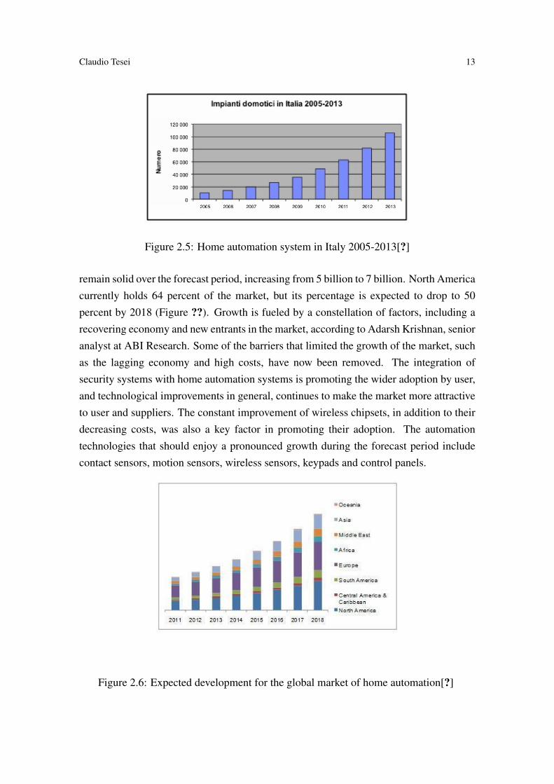
The CERP, an organization that gather the research projects of the European Union inthe field of Internet of Things [?], shows the home automation and intelligent buildingsamong the most promising areas of application. The use of wireless communication tech-nologies (ZigBee, 6LoWPAN, etc.) allows you to connect to each other objects within abuilding providing two-way communication. In the past, home automation technologieswere mainly used in offices and luxury homes, but the technological development and thepermanent reduction in costs now make these technologies accessible to a growing partof the population. The features offered are varied and constantly evolving. For example,you can use the temperature and humidity sensors to collect the data needed to optimizethe use of heating and air conditioning, ensuring comfort and at the same time reducingenergy consumption. An important role is also played in helping the people, given thatthe home automation solutions can be used to monitor the activities of people within thehome, providing assistance to elders or individuals with disabilities in the performance ofactivities of daily living and, in case of need, make alarm. In Italy, the home automationmarket developed with the growth trend (data Assodomotica) at around 30% per annum.The trend has been to create home automation systems in new homes or renovated. In ourcountry about 300,000 homes per year are built and around 700,000 are restructured withthe complete renovation of the electrical system. Home automation systems have grownfrom 10,000 in 2005 to over 100.00 in 2013 (Figure ??). The total value of these implantswent from 42 million euro in 2005 to 440 million euro in 2013. These figures includeboth basic electrical systems (normally included in the offers of new buildings), and ad-vanced systems, with high levels of customization. Assodomotica identifies four marketsegments. The first referred to "advanced applications" covers housing and extended lux-ury homes. The advanced systems require a custom project, which involves, in additionto the installer, designer and architect. The second segment of the market concerns thesystems made by the installer directly on the final user. The third segment is the one of"Basic systems" provided in the offer by the construction companies and the fourth is theone regarding applications which are intended for the elderly and disabled. The fastestgrowing segments are the advanced applications and basic systems. As for the last one, astrong pushes has been given by the growing sensibility regarding energy savings.
2.2.7 How will develop the global market
According to ABI Research the global market of home automation is trending upwardswith significant growth expected over the next few years[?]. With 9 billion USD in 2014,the market is expected to reach 14 billion by 2018. The North American market will
Claudio Tesei 13
Figure 2.5: Home automation system in Italy 2005-2013[?]
remain solid over the forecast period, increasing from 5 billion to 7 billion. North Americacurrently holds 64 percent of the market, but its percentage is expected to drop to 50percent by 2018 (Figure ??). Growth is fueled by a constellation of factors, including arecovering economy and new entrants in the market, according to Adarsh Krishnan, senioranalyst at ABI Research. Some of the barriers that limited the growth of the market, suchas the lagging economy and high costs, have now been removed. The integration ofsecurity systems with home automation systems is promoting the wider adoption by user,and technological improvements in general, continues to make the market more attractiveto user and suppliers. The constant improvement of wireless chipsets, in addition to theirdecreasing costs, was also a key factor in promoting their adoption. The automationtechnologies that should enjoy a pronounced growth during the forecast period includecontact sensors, motion sensors, wireless sensors, keypads and control panels.
Figure 2.6: Expected development for the global market of home automation[?]

14 Rule Based Control System for Home Automation
Some of the features that are added to the home for safety reasons are expected toget substantial gains. "We expect to see the most growth in door locks, thermostats andsmart plugs", said Krishan[?]. The demand for a universal solution, easy to install andintegrated with several subsystems in a home, led to a phase of explosive growth in theindustry.
2.2.8 The main players
To understand better the potential of our product we can compare it with the solutionsthat are available on the market. After a research made on internet it was possible tocreate a list of competitors, it was decided to divide that list geographically and by typeof service offered, so as to highlight both the potential and the gaps of each proposal onthe market.

Claudio Tesei 15
Direct CompetitorIndirect Competitor
In our regionThe table below shows three main competitors, founded looking near by our region, whichis called Marche. It was decide to differentiate these three companies from the one listedin the section (Italy), in order to understand if our solution (Kaalisy Domotics) could haveany chance to be competitive in this specific region of Italy.
Competitor Product Strengths Weaknesses
Seav SEAVDOMUS
- Web interface design,for home automation,system- Compatible with Radio,technology 433.92 MHz
- Wiring of the system bya qualified technician- Proprietary communicationprotocol- Invasive modification of theelectrical part of the existing
I.E.T domoticae automazione
- 30 years in the market- Compatibility standard KNX
- Invasive intervention andmodifies electrical system- Web Page unintuitive
Domsolution SmartSolution
- Modularity- Ability to create dedicatedscenarios
- Proprietary communicationprotocol- Invasive intervention andmodifies electrical system
16 Rule Based Control System for Home Automation
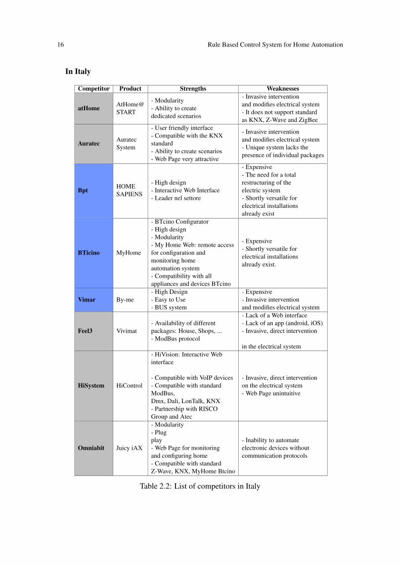
In Italy
Competitor Product Strengths Weaknesses
atHome AtHome@START
- Modularity- Ability to creatededicated scenarios
- Invasive interventionand modifies electrical system- It does not support standardas KNX, Z-Wave and ZigBee
Auratec AuratecSystem
- User friendly interface- Compatible with the KNXstandard- Ability to create scenarios- Web Page very attractive
- Invasive interventionand modifies electrical system- Unique system lacks thepresence of individual packages
Bpt HOMESAPIENS
- High design- Interactive Web Interface- Leader nel settore
- Expensive- The need for a totalrestructuring of theelectric system- Shortly versatile forelectrical installationsalready exist
BTicino MyHome
- BTcino Configurator- High design- Modularity- My Home Web: remote accessfor configuration andmonitoring homeautomation system- Compatibility with allappliances and devices BTcino
- Expensive- Shortly versatile forelectrical installationsalready exist.
Vimar By-me- High Design- Easy to Use- BUS system
- Expensive- Invasive interventionand modifies electrical system
Feel3 Vivimat- Availability of differentpackages: House, Shops, ...- ModBus protocol
- Lack of a Web interface- Lack of an app (android, iOS)- Invasive, direct intervention
in the electrical system
HiSystem HiControl
- HiVision: Interactive Webinterface
- Compatible with VoIP devices- Compatible with standardModBus,Dmx, Dali, LonTalk, KNX- Partnership with RISCOGroup and Atec
- Invasive, direct interventionon the electrical system- Web Page unintuitive
Omniabit Juicy iAX
- Modularity- Plugplay- Web Page for monitoringand configuring home- Compatible with standardZ-Wave, KNX, MyHome Btcino
- Inability to automateelectronic devices withoutcommunication protocols
Table 2.2: List of competitors in Italy

Claudio Tesei 17
In the world
Competitor Product Strengths Weaknesses
Revolv Revolv
- Plug&play System,- Easy to configure,- Low cost (299$),- Application for Smartphonesintuitive,- Availability of a Community,- Nice Design
- Compatible with few smart devices
SmartThings Hub
- Low cost ($99),- Plug&Play,- Easy to Use,- Strong Community,- Modularity,- Compatiblewith Z-Wave ZigBeeand Wi-Fi devices,- Arduino Compatibile
- Compatible with few smart devices
Table 2.3: List of competitors in the world
18 Rule Based Control System for Home Automation
The Table ?? was made collecting all the information regarding one company, thenanalyse them and comparing with precise parameters. It was decided to divide all thecharacteristics founded into two main categories (Strengths, Weaknesses). To list theweaknesses and the Strengths the following parameters were chosen:
• Cost (Is it expensive?)
• Invasive (Does it require the modification of the house’s electrical system?)
• Compatibility (Can it work with other product?)
• User-friendly (Does it provides an intuitive user interface?)
• Easy-to-use (Is it possible to install it by yourself?)
We used these parameters according to the characteristic of our product, in that way itis possible to have a clear vision of what can do kaalisy Domotics.
2.3 The product, process or invention: the value propo-sition
2.3.1 How has it started
It all started from our personal desire: to control the lights using a smartphone in thehouse. Unfortunately, there was no possibility to change and modify the structure ofthe electrical system. As we did not find any easy and accessible way in the market,we decided to solve the problem by creating our own home automation system that usesopen-hardware platforms. Taking note of the satisfactory results obtained, we decidednot to stop there, but we continued to add new components in our system to increasethe control on the house. Also, we decided to work from the software side, and havean overall improvement in terms of "Human-Computer-Interaction". We have made thesystem customizable, adaptable to every need of the user. Then, gathering feedback fromfriends, relatives, colleagues and academics, we found that our needs matched with needof many others so the desire to transform our system into a business idea was born.
We have already had the opportunity to concretely demonstrate our technical skillsin a previous project, developed as part of our studies at the University of Camerino."Unicam Solar" Figure?? is a hardware/software system for monitoring power control ofphotovoltaic panels on web and on mobile devices.

Claudio Tesei 19
Figure 2.7: "UnicamSolar" developed for the University of Camerino (2013)
2.3.2 The product
Our system, "Kaalisy Domotics", offers several packages that are easy to install and atan affordable price. This will allow users to create a modular system that fully adaptsto their needs and grows with their requirements. There will even be the possibility tointegrate the packages of other companies into our system, thanks to the use of the Z-Wave protocol. The initial basic product includes a small number of packages, enoughto cover the main control requirements of the housing unit. Later the offering will beexpanded and diversified, always keeping an eye on the development of the market andtechnology to avoid ending up with the product becoming obsolete.
Figure 2.8: Logic view of "Kaalisy Domotics" system
The system (Figure??) consists in a central unit connected to the internet, which allowsusing and programming all packages inside the house through a user-friendly interface onsmartphones (app) or web browser. The packages (listed below) are plug & play, easy toinstall and it does not require any intervention on the electrical system. Once installed inthe house, the packages are automatically detected by the system. Then, by accessing to

20 Rule Based Control System for Home Automation
the user interface configuration, the user will be able to watch a quick tutorial that willexplain how to set-up and use the features of the packages.
Installation Comunication Function Dimension Alimentation
Central Unit-Connect to therouter viaethernet cable
-Wireless viaproprietary protocol(used byour packages),-Z-Wave
-Server-Web to App andconfiguration pagethrough browser,-Database,-Management AndControl Software,-Allows to control
60x10x20mm
Wallplug
Bulb adapter- Screw to E27 plugbefore bulb,- Install,connectingthe cables of thetwo phases in caseof neon, lampadare,etc. ..
-Wireless viaproprietary protocol(used by,our packages)
- Remote switch 30x30x50mm
E27plug
Switch- Replace the presentswitch,or,- Cover the presentswitch
-Wirelessvia proprietaryprotocol(used by our packages)
-Switch 110x70x20mm Battery
Wall Plug Adapter-Connect betweenthe wall plug andthe appliance
-Wirelessvia proprietaryprotocol(used by our packages)
- Monitorapplianceconsumption,- Remote switchto appliance
40x40x50mm
Wallplug
Thermostat
- Replace with thepresent thermostat
-Wireless viaproprietary protocol(used by our packages)
- Adjustmentmanual /remote /programmedof the temperature
120x60x40mm Battery
Door Opening - Fix to the wall,- Connecting withthe lock control cable(it can be usuallyfind in the handset)
-Wirelessviaproprietaryprotocol(used by our packages)
- Remoteopening door
70x50x20mm
Battery/Wall plug
Sensor
-Fixto the wall
-Wirelessviaproprietary protocol(used by our packages)
- Remote Controlof the temperatureandhumidity,- Detects:Gas spill,flood, fire principle
140x40x30mm
Battery/Wall plug
Surveillance Camera
-Fixto the wall -Wi-Fi
- Remote videomonitoring,- Motion detection
80x80x80mm
Wallplug
Table 2.4: Specification of the packages

Claudio Tesei 21
Figure 2.9: Dwelling with a Kaalisy Domotics system
The packages can be controlled ("Switch", "Shut Down", "Open", "Increase", etc...)Smartphone App (downloadable from the Play Store or the App Store), that also allowsto control the system by voice. The scenarios (i.e. "If the camera detects motion then turnon the lights and raise the temperature to 20 �C inside the room") are programmable onthe simple web interface through the browser. The interface design is very nice, aimed tobe easy-to-use.
2.3.3 Placing on the market
Competitors and our solution have been mapped in the differentiation diagram of Figure??in which the dimensions considered are the method of communication (ranging fromwired solutions into completely wireless solution) and the completeness of the product(offer complete - control + components - or only controller).
Figure 2.10: Differentiation diagram of the products present on the market
Wireless solutions that currently exist are not complete as wired systems because not allswitches, light bulbs, and appliances can be operated wirelessly. The wireless solutionsavailable on the market require the purchase of a Central Unit compatible with the most

22 Rule Based Control System for Home Automation
frequently used wireless communication protocols (Zigbee, Z-Wave, etc...). Therefore theresearch, from different companies, of the components (switches, bulbs locks, appliances, etc...) able to communicate with the central unit purchased, discourages many buyersbecause it requires technical competence and a great deal of time to use the "do it yourself"home automation system. Kaalisy Domotics is placed in a segment of the market of homeautomation still empty, offering a complete solution easy to install and low cost thanks towireless technology.
2.4 The marketing plan
2.4.1 Product
The product of Kaalisy Domotics is aimed at users that are interested to make their ownhome "smart" in a simple and economical way. The solution may be purchase completelyor partially (one package at a time).

Claudio Tesei 23
Package Name Description
Central Unit
Kaalisy
The brain of thewhole home automationsystem, manages all theinformation from differentinstalled packages and isresponsible for the actionstaken by the packages.
Bulb Adapter
Lumus
A device of small dimensionsthat is connected between thebulb and the lamp holder,allowing to make smart everysingle light.
Switch
Lumus Switch Wall
An intelligent switch that,allows to make smart everyswitch points. It may beinserted in the place of theswitch or if you preferabove the breakersthemselves.
Wall Plug Adapter
Wally
A wall outlet where smartappliances, televisions andhousehold appliances areconnected.It allows you to:- Controlling consumptionof each device connectedto it- Turn on and off connecteddevices,Receive notificationswhen the consumption exceedsa certain threshold
Thermostat
Ocio
A compact device that inaddition to provide all thefunction of a thermostatis able to interact with thecentral unit allowing theuser to create scenariosincreasingly dynamically.
Door Opening
LockerAllows the user to makesmart key locks in the home(door entrance, gate of the house).
Sensy
SensyAllows the user to makesmart key locks in the home(door entrance, gate of the house).
Surveillance Camera
Intrusor
It offers the possibilityof introducing a Web Cam,allowing the user to monitorin real time what happens intheir own home.
Table 2.5: Functions of the packages
24 Rule Based Control System for Home Automation
Kaalisy is also compatible with all Z-Wave devices, which allow the customer to usein addition to our packages, which use an owner communication protocol, also any otherdevices already in its possession and based on Z-Wave. When a package fails, the systemwill note the absence of such package and will inform the user, who may replace it, free ofcharge if it happens during the warranty period provided by law. In case of failure on thecentral unit, every package will go in "Single mode" and will work independently fromthe others. This will cause the loss of management scenarios and remote management;the rest will be like in a not smart house.
2.4.2 Price
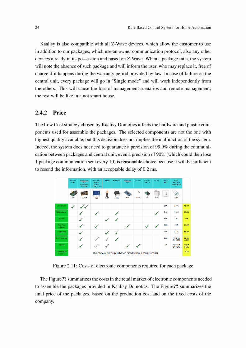
The Low Cost strategy chosen by Kaalisy Domotics affects the hardware and plastic com-ponents used for assemble the packages. The selected components are not the one withhighest quality available, but this decision does not implies the malfunction of the system.Indeed, the system does not need to guarantee a precision of 99.9% during the communi-cation between packages and central unit, even a precision of 90% (which could then lose1 package communication sent every 10) is reasonable choice because it will be sufficientto resend the information, with an acceptable delay of 0.2 ms.
Figure 2.11: Costs of electronic components required for each package
The Figure?? summarizes the costs in the retail market of electronic components neededto assemble the packages provided in Kaalisy Domotics. The Figure?? summarizes thefinal price of the packages, based on the production cost and on the fixed costs of thecompany.

Claudio Tesei 25
Figure 2.12: Selling prices of the packages
The Figure?? compares the competitive prices of some packages present in the offerof Kaalisy Domotics against the equivalent best solution (based on sales and reviews) onthis site www.smarthome.com.
Figure 2.13: Selling prices of comptetitor’s products
2.4.3 Sales channels (Placement)
The sales channel chosen is the e-commerce. A web site will provide to the customers allthe features and the informations about our company and our products. Moreover the webwill be used as point of sale and point of care. This choice allows to reduce the final costof the product to the buyers by eliminating the increases of price which would be causedby distributors and retailers and reducing the costs of management sales and service. It isa strategic choice made by considering the target market, or people, usually in possessionof smartphone and/or tablet and with a certain confidence with computers and electronics,used to seek and buy on the Internet. In addition, this eliminates the territorial barriers andmakes possible future expansion on the international market. Products purchased on-linewill be sent to the buyer by delivery service carried out by couriers.
2.4.4 Promotion
An aggressive advertising campaign is planned starting on internet channels (AdWordsand social networks) to attract potential buyers on our website. Around the website, using

26 Rule Based Control System for Home Automation
the social media, we intend to create a community of customers and fans of KaalisyDomotics so that they can communicate and exchange information and suggestions aswell as provide new ideas, at the same time helping us to understand the real customerneeds. As soon as possible we intend to launch advertising campaigns also on the moretraditional channels, to reach those who are less informed in technology development andtherefore cannot imagine which are the offer became possible thanks to low cost smartsolution. We will use radio campaigns, at least on the local radio stations, press campaignson free press and after local press, in order to increase the visibility of our product. Duringfurther growth we would even get to the national press and maybe even to reach the TVchannel, initially local and then national. We will not neglect the traditional channels; weintend to participate at the italian fairs about home and home furnishings that are opennot only to the industry but especially to the final customers. These occasions can alsobe used for promotion. We expect partnerships with local companies that are operating inthe field of plant and electrical installers/designers who could then offer to its customersa complete solutions very interesting.
2.5 Operational Plan
2.5.1 Roadmap
What has been developed so far is still at the prototype stage. A standardization andindustrialization phase of the production of each component is required. Before to insertthe packages in the market it will be also compulsory to obtain the CE certification. Themain steps expected, with their timing, are illustrated in Figure?? Gantt Overall. Thephase of product development is estimated at 6 months. After that the operation phasewill begin.
Figure 2.14: Roadmap of the product’s development
Throughout the start-up phase (first 3 years), we identified the following milestones:
First 6 months:Product development and CE certification

Claudio Tesei 27
End of second year:Extension the compatibility to other communication standardsDevelopment of new packages
End of the third year:Development of new packagesReady to start marketing in Europe . . .
2.5.2 Compliance of the system
The buyer should have the security of buying a product which conforms to the currentregulations in the field of electronics. In this regard, it will be necessary to comply withDirective 2006/95/EC on Low-voltage equipment, and then get a CE sign. At thisstage, we consider to consult a Notified Body, which will deal with the preparation of theEC Declaration of Conformity, and will assist us in filling the Technical Documentation.The contribution of this organization will allow us to speed up this phase and in about twomonths we will be able to print the CE mark on our products. The costs are around 1,500to 2,500e for the consulting and the certification.
2.5.3 Make or buy?
When the design of our products will be ready we intend to rely on an experienced com-pany, which uses automated systems and is able to assemble at cost and time absolutelyunreachable for us. To simplify the simulations, we assumed economic and financial costof the assembly as an overhead of 10% compared to the cost of materials.
2.5.4 Operation characteristics
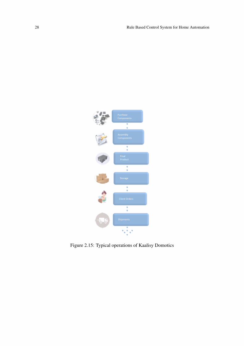
Once the production of packages will be standardized, the operations will take place asrepresented in Figure??Purchase Components
The electronic components will be purchased from Supplier1 and will be sent di-rectly to the Assembly Company. The cover of each individual packages will bepurchased from the Supplier2 and directly shipped to our company.
Components AssemblyThe components are assembled by the Assembly Company and sent to our Com-pany.
28 Rule Based Control System for Home Automation
Figure 2.15: Typical operations of Kaalisy Domotics
Claudio Tesei 29
Final productRequire the software installation and the application of the cover for every singlepackage assembled.
StorageThe final products are stored in a warehouse and ready to be sold. Then it will beimportant to take care of the management of the inventory, orders and stocks.
Customer OrdersThe orders will be reported by the website to the shipping manager, who picks upthe products from the store, prepare and carry out the shipment.
ShippingIt will be provided through couriers to ensure a safe and prompt delivery.
2.5.5 Technical Assistance
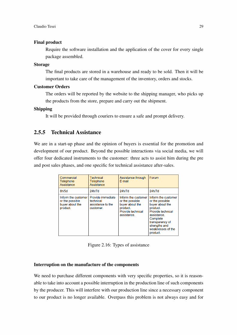
We are in a start-up phase and the opinion of buyers is essential for the promotion anddevelopment of our product. Beyond the possible interactions via social media, we willoffer four dedicated instruments to the customer: three acts to assist him during the preand post sales phases, and one specific for technical assistance after-sales.
Figure 2.16: Types of assistance
Interruption on the manufacture of the components
We need to purchase different components with very specific properties, so it is reason-able to take into account a possible interruption in the production line of such componentsby the producer. This will interfere with our production line since a necessary componentto our product is no longer available. Overpass this problem is not always easy and for

30 Rule Based Control System for Home Automation
this reason we will first take it into account in the negotiations phase with the supplier/-manufacturer. If this should be not enough, we will be forced to redesign the Hardwareand Software part involved by that component. In the projecting phase we will try to mit-igate this risk by trying to develop each part quite independently from the components,especially for the Software part. This will allow us to replace more easily the involvedcomponent, even if it was a voluntary choice, derived from the arrival of componentsconsidered better of that in the market.
Computer security
Security is a delicate aspect especially in the home automation field. With the purposeof offer to the customers a safe product, Kaalisy Domotic opted for a local solution,providing at the buyer the full management system in a single device, connected only tothe home router. Such solution allows to avoid the use of an external server (where toinstall the entire management system), which are more susceptible to attacks by hackers,thereby reducing the risk of intrusion. The proprietary communication protocol as wellas permit the different devices to communicate each other adds even an additional layerof security by encrypting communications in order to prevent any intrusions during thecommunication between the devices and the central system.
Intellectual property
Like most of our competitors, we intend to protect the rights of our intellectual propertythrough patents where possible. Not all packets will be patented, for example in the caseof the central unit that uses an open-hardware platform will be patented only the softwarepart. The initial cost of patents is around 10,000e, in later years the maintenance costwill be increased by approximately 20% for annuity starting from 600efor the first yearof maintenance.
2.6 Organizational Structure
2.6.1 Value chain
The value chain of Kaalisy Domotics implements all the primary activities identified byPorter Figure?? logistics inputs, operations, logistics outputs, sales, marketing and ser-vices. The activities of (support for Porter) R&D and Procurement are also essential forour company. In the organization chart of the company (Figure??) are identified the func-tions responsible for each activity.

Claudio Tesei 31
Figure 2.17: The primary and support activities of Porter’s Value Chain for Kaalisy Do-motics
2.6.2 Organization chart of the company
Figure 2.18: Organization of Kaalisy Domotics
CDABoard of Directors. Formed by the 5 founders, who will play the roles of Executive,will be the place where strategic decisions are taken.
CEOChief Executive Officer. Responsible for the implementation of strategic decisionswithin the company and the administrative / legal, personnel management.
CFOChief Financial Officer. Head of financial assets.
CTOChief Technical Officer. Responsible for the activities of product development and

32 Rule Based Control System for Home Automation
technology (R&D). It also coordinates all activities and personnel related to hard-ware and software development.
CMOChief Marketing Officer. Responsible for the activities of sales, marketing and com-munications and customer services. It also coordinates all activities and personnelrelated to design, including the on of the website.
COOChief Operating Officer. Responsible for procurement, logistics and input and out-put operations. It also coordinates all activities related to the management and stafforders.
2.7 The economic and financial plan
To estimate the amount of sales of the devices we started with the data provided by As-sodomotica and we have estimated the number of new plants planned in the next 3 years,assuming a reasonable penetration of the market (Figure??) and taking into account thatin the first year sales will begin only in the second half of the year.
Figure 2.19: Hypothesis of market penetration
The economic and financial simulations were made based on the configuration typeenvisaged in Figure??.
Figure 2.20: Type of configuration expected

Claudio Tesei 33
Figure 2.21: Plan of sales by product
All the other financial analysis are showed on the Appendix 1.

34

35
Chapter 3
Software Design
3.1 Purpose of the System Design Document
The Design Document has to be a way to arrive at the implementation part with the know-how which allow to fulfil the requirements. This part has no value if the reader has notread the Software Requirement Document that is in the Davide Angelici MSc thesis. Inthis document we will explain the design of all the System, starting from a general schemethat represents all the components until reach the design of the software. We know fromthe requirements documentation, which contain all the property that the system must have,how the system intend to meet the users needs. It depicts a guideline to the implementa-tion; even if in that phase some changes could be done, due to some eventual problemsthat could occur, the most of the notions written here will be respected.
3.2 General Overview
To describe the realization of the system, we begin from a logical overview in which ispossible to recognize all the component present in the Kaalisy Domotic offer, but morerelevant is to understand how they are connected together, and which role they have withinsuch a system. Then, once we have outlined the architecture, we will introduce the hard-ware components that form it. For each component employed to build the system, there isa brief description and a table with its technical specifics; in this way, if the reader is a bitskilled, he should be able to understand by himself that the components satisfy the func-tioning. Next to the Architecture design, is present the Software Architecture, in whichis explained the System from a software point of view, in particular the technology thatwe are going to use to implement the specific parts of such system. Once that the readerhas a good overview of the components, from both Software and Hardware part, it is time
36 Rule Based Control System for Home Automation
to show how the communication works between the Central Unit and the other Packages.Then, everything should be clearly enough to pass to the design of the Database, anddelineate the inputs and outputs of the system.
3.3 Design Considerations
In this section will be listed all the issues which need to be resolved in order to achieve acomplete design solution.
3.3.1 Goals and Guidelines
The goal of this project is to create a home automation system which is plug&play, pur-chasable at an affordable cost. Moreover, it has to be easy to use and give to the enduser an easy way to control it; to provide all of these functionalists the system must bedesigned respecting some rules:
• The communication protocol should privilege the reliability instead of to the veloc-ity.
• An affidable structure event condition action (ECA) has to be created to manage therules (Scenario).
• The software should be as independent from the hardware as possible.
• Write a language that allow the user to insert the rules in an easy way.
• The central unit has to recognize every new packet in the system and install it.
• The User Interface has to be easy-to-use.
These are the goals that our system must comply to be in line with the requirements;every goal has its critical parts and require a lot of work in the design part to be avoided.The first and the second ones are the most complicated to achieve, and they will requiremore effort than any other to be accomplished. To be sure that each packet sent reachthe destination we need to implement a really reliable communication protocol. Createan ECA structure and let the user insert the rules, means the possibility to have someinconsistent rules that may create a loop or other problems, so it is necessary to find asolution to this problem in the design part.
3.3.2 Development Methods
The methods that we are going to use to develop the design of the system and of the soft-ware are UML and sometimes Object-Oriented, to be more precise. An house automation

Claudio Tesei 37
system is composed of several parts, and the design can become complicated or confused;this bring us to choose UML rather than a textual modeling language. UML simplifiesalso the work when cooperating with other people, and uses diagrams which are easy tounderstand and to modify, even after the development of the whole system.
3.3.3 Architectural Strategies
We had decided to use Open-Hardware platforms as bases, and to develop our system onthose. This allows us to spend less time on the design hardware phase. Regarding thesoftware part instead we will employ just a few libraries aimed to the use of the principalfeatures of the Open-Hardware platforms, while the most part of the software will bedeveloped by us. Although developing a communication protocol can take a considerableamount of working hours, it brings a lot of advantages, such as an improvement in thesecurity, or the possibility to balance the velocity and the reliability according with ournecessities. The most of the code will be written to program the central unit, the core ofthe system: the ECA structure, the web server and the database will reside there.
3.4 Hardware Architecture Design
This section outlines the system and the hardware architecture design that will be subse-quently implemented.
3.4.1 Logical View
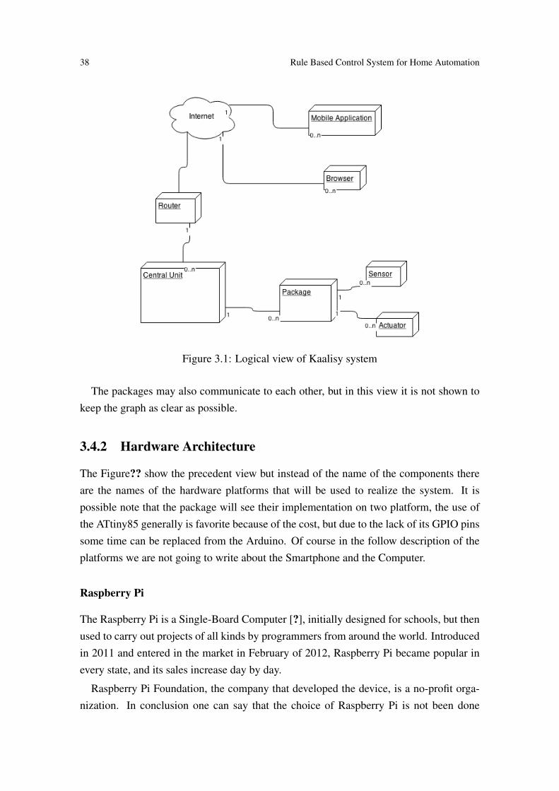
In the graph below it is represented an overview of the system: without gooing too deepinto the specifics, it is shown how the main components are connected to each other.
Components:Central Unit: Manages the packages and connects everything to Internet through therouter.Packages: Provide connection to the actuators and to the sensors; they constitute accesspoint to the house environment, and take order from the Central Unit.Sensor: Collects information from the environment.Actuator: Acts on the environment.Browser / Mobile Application: Provides interfaces to the user to give instruction to theCentral Unit.
38 Rule Based Control System for Home Automation
Figure 3.1: Logical view of Kaalisy system
The packages may also communicate to each other, but in this view it is not shown tokeep the graph as clear as possible.
3.4.2 Hardware Architecture
The Figure?? show the precedent view but instead of the name of the components thereare the names of the hardware platforms that will be used to realize the system. It ispossible note that the package will see their implementation on two platform, the use ofthe ATtiny85 generally is favorite because of the cost, but due to the lack of its GPIO pinssome time can be replaced from the Arduino. Of course in the follow description of theplatforms we are not going to write about the Smartphone and the Computer.
Raspberry Pi
The Raspberry Pi is a Single-Board Computer [?], initially designed for schools, but thenused to carry out projects of all kinds by programmers from around the world. Introducedin 2011 and entered in the market in February of 2012, Raspberry Pi became popular inevery state, and its sales increase day by day.
Raspberry Pi Foundation, the company that developed the device, is a no-profit orga-nization. In conclusion one can say that the choice of Raspberry Pi is not been done

Claudio Tesei 39
Figure 3.2: Architecture view of Kaalisy system
Figure 3.3: Raspberry-Pi

40 Rule Based Control System for Home Automation
only for its excellent hardware, but even for the community that is developed around thisdevice.
Technical SpecificationsPrezzo di offerta: 27ASoC: Broadcom BCM2835 (CPU + GPU + DSP + SDRAM)CPU: 700 MHz ARM1176JZF-S core (famiglia ARM11)GPU: Broadcom VideoCore IV, 1080p30 H.264 high-profile decodeMemory (SDRAM): 512 Megabytes (condivisa con la GPU)USB 2.0 ports: 2 (through an integrated hub USB)Output video: Connector RCA to composite video, HDMIOutput audio: 3.5 mm jack, HDMIMemoria: SD / MMC / SDIO card slotCollegamenti di rete: Ethernet 10/100 (RJ-45)Periferiche di basso livello: 2x13 header pins for GPIO, UART, +3.3 Volt, +5 VoltReal-time clock: No clock or batteryPotenza assorbita: 700 mA, (3.5 Watt)Alimentazione: 5 Volt via MicroUSDimensioni: 85.60mm Π53.98mm (3.370 inch Π2.125 inch)S.O. supportati: Debian GNU/Linux, Fedora, Arch Linux e GentooS.O. non supportati: RISC OS (shared source)
Table 3.1: Raaspberry-Pi Technical Specifications
Arduino
Arduino unlike the Raspberry Pi is called Single-Board Microcontroller; the differenceis in the integrated circuits: Arduino has a micro-controller, while Raspberry Pi a micro-processor. Arduino is designed to physically interface to a system, through digital andanalog pins, for this reason is used in many projects of automation. Designed in Italy in2005 and sold to the public since 2008, Arduino now is part of several projects carriedout for commercial and educational purposes. the Community which is developed behindArduino is huge, this is probably because is an open-source hardware platform, so anyonecan build an Arduino or making any changes.
Figure 3.4: Arduino Pro Nano
ATtiny85
The ATtiny85 is a great substitute to the Arduino[?]. It can run the most of the Arduinoprograms, but is cheaper and smaller. As can be seen from the Technical Specification
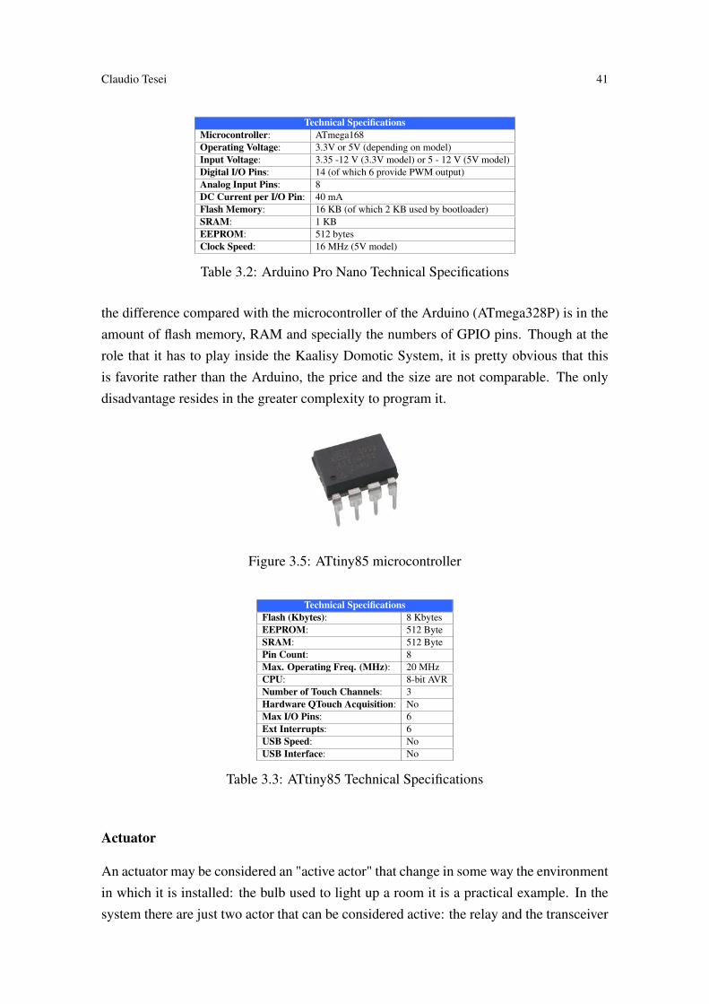
Claudio Tesei 41
Technical SpecificationsMicrocontroller: ATmega168Operating Voltage: 3.3V or 5V (depending on model)Input Voltage: 3.35 -12 V (3.3V model) or 5 - 12 V (5V model)Digital I/O Pins: 14 (of which 6 provide PWM output)Analog Input Pins: 8DC Current per I/O Pin: 40 mAFlash Memory: 16 KB (of which 2 KB used by bootloader)SRAM: 1 KBEEPROM: 512 bytesClock Speed: 16 MHz (5V model)
Table 3.2: Arduino Pro Nano Technical Specifications
the difference compared with the microcontroller of the Arduino (ATmega328P) is in theamount of flash memory, RAM and specially the numbers of GPIO pins. Though at therole that it has to play inside the Kaalisy Domotic System, it is pretty obvious that thisis favorite rather than the Arduino, the price and the size are not comparable. The onlydisadvantage resides in the greater complexity to program it.
Figure 3.5: ATtiny85 microcontroller
Technical SpecificationsFlash (Kbytes): 8 KbytesEEPROM: 512 ByteSRAM: 512 BytePin Count: 8Max. Operating Freq. (MHz): 20 MHzCPU: 8-bit AVRNumber of Touch Channels: 3Hardware QTouch Acquisition: NoMax I/O Pins: 6Ext Interrupts: 6USB Speed: NoUSB Interface: No
Table 3.3: ATtiny85 Technical Specifications
Actuator
An actuator may be considered an "active actor" that change in some way the environmentin which it is installed: the bulb used to light up a room it is a practical example. In thesystem there are just two actor that can be considered active: the relay and the transceiver

42 Rule Based Control System for Home Automation
(transmitter part). To command this actuator we do not need any kind of driver circuit, allthat is required is embedded in the Arduino or ATtiny85.
Sensor
A sensor, in contrast, can be considered "passive actor", which reads the state of theenvironment and communicate it to the system without modifying any part. Thermome-ters, luminosity and humidity sensors, switches, smoke or gas detectors, and many othercomponents are considered sensors. Even if it does not perform actions within the envi-ronment are essential to check the status: usually an actuator is activated after the signal(read state) sent by a sensor. The installation of the sensors usually does not depend fromthe type, their function is to read a number and send it to the Arduino or ATtiny85, whichwill have to simply translate it into an integer that has meaning for the system and forwardit to the Management System.
Other Components
In this document we are not facing some issue as: the supply needed from this platform,the design of the circuits and the PCB. These are not a small issue in which we will neverface, on the contrary they may become insidious problem. But this is not the topic of suchdocumentation, it is enough to let know at the reader that we found a perfect power supply(LS03-15B05SR2[?]) that consume less than 1W and is as cluttered as an Arduino ProMini. To the circuit until now we rely on the scheme found in Internet that are really wellmade.
3.5 Software Architecture Design
In this paragraph we are going to introduce the Software Technology that we intent touse to build the system. In the Figure?? it is show how they will be employed, in whichplatform they will be installed. A deeply explanation of the technology will be done in theimplementation chapter, here they are just listed and their roles are just outlined.
3.5.1 Central Unit
The central Unit is the brain of the entire system, it will contain:The Server: used to allow the communication between the system and the outside devices(smartphones, workstation). It was decide to use Apache http 2.4.10 [?] with PHP5.

Claudio Tesei 43
Figure 3.6: Software view of Kaalisy system

44 Rule Based Control System for Home Automation
The Databases: where all the informations are stored, which is accessible from the man-agement software. The databases used is MySQL, because it is open source and is themost used database system[?].The Management Software: Responsible to change the state of the system according tothe input of the user. It is written in Java, because it is a portable language and it does notneed to be recompiled in the case of changing type of platform.The Configuration Web Page: It allow the user to interact with the system, the web pageis written in HTML5, CSS3 to set up itŠs mockup and structure. JavaScript and jQuerywill be used to perform all the access and request from the client to the server and vicev-ersa.
3.5.2 Packages
The packages are the end devices installed in the house. Their function is to performactions send it by the Central Unit. Their are programmed using open source librarieswhich will be installed into open hardware components.
3.5.3 Mobile App
The Mobile application is used to interact with the system by smartphone. It is developedin Android or iOS depending on which operating system is installed. Its main functionis to perform the classic GET/POST request from the Server. Moreover the application,thanks to the Google speech recognition libraries, it is able to perform user inputs by voicecommands.
3.5.4 Workstation
It simple consiste to redirect the user to the Configuration Web Page, where it can changesettings and creates scenario, all the modifications are saved into the system and accessiblethrough mobile app.
3.6 Internal Communications Architecture Design
In order to satisfy the requirements of the system the topology of the network as a Mesh,it is necessary. This kind of network it is difficult to implement and configure, but itgives important and essential advantages : fault tolerance, easy to troubleshoot and therange of the signal is as large as possible. Each package communicate with all the others

Claudio Tesei 45
(within the range of the signal), this create an overload on the packets sended and morein general in the traffic over the network, but this overload is insignificant compared withthe advantages that takes this type of topology.
Figure 3.7: Mesh Network view
Furthermore, we want that the system is capable to understand when a new packageenters for the first time in the network and auto-install it, in order to allow the auto-recognition of the packages we have to properly implement the communication proto-col.
3.6.1 Communications Hardware Architecture
To be in line with the goals of the project, we need a cheap transceiver, with a signalthat has a good range and a restrained power consumption, careless the bandwidth andspeed of the signal. Thus we opted for two solutions, one already standardized with hiscommunication protocol and another cheaper but devoid of any protocol, both use a low-power RF radio. The first is the well-known Z-wave will be installed only on the centralunit to provide compatibility at all the Z-wave packages already in the market and for theour packages a nRF24L01+ transceiver will be used.
nRF24L01+
Figure 3.8: Transceiver nRF24L01+

46 Rule Based Control System for Home Automation
Technical Specifications
Power consumption:900nA deep sleep mode11.3mA Radio TX at 0dBm13.3mA Radio RX at 2Mbps on-air data-rate
Radio specifications:
2.4GHz ISM band operationGFSK modulation, 1 or 2MHz bandwidth0, -6, -12, and -18dBm programmable TX output powerConfigurable on-air data rate of 250kbps, 1Mbps or 2Mbps-94dBm RX sensitivity a 250kbps-82dBm RX sensitivity at 2Mbps-85dBm RX sensitivity at 1MbpsExcellent co-existence performanceCompatible with a 16MHz s60ppm crystal
Interfaces: SPI, up to 10Mbps
Power supply: Internal linear voltage regulator1.9 to 3.6V supply range
Temperature range: -40 to +80 žC
Table 3.4: nRF24L01+ Technical Specifications
Z-Wave
There are different transceiver with the capability of implement the Z-wave standard, theone that we are going to use in this project is the ZM3102.
Figure 3.9: ZM3102 Transceiver
3.6.2 Communications Software Architecture
The main goal of the nRF24L01+ transceiver is to allow all the devices to share andexchange informormatios. All the transceiver are programmed taking into account thatthey have to be efficient and reliable, than it was decided to let them spend almost all theirlife cycle in sleep mode, in order to decrease the energy consumption, and wake it uponly when they have to perform/process some actions. To accomplish the exchanges ofinformations between the package and the central unit, an own communication protocolsis realized. It is responsible to :
• synchronize the data flow
• detect and prevent the loss of informations exchanged

Claudio Tesei 47
Technical Specifications
Power consumption:
TX@-5dBm = 24mATX@0dBm = 36mARX = 23mAPower down/sleep mode = 2.5 tA
Radio specifications:
Freq for 9.6kbps / 40kbps EU: 868.42 / 868.40MHzHigh Sensitivity (-102/-98 dBm) FSK Modulation9.6kbps/40kbps Data Rate-22.0dBm to -2.0dBm Output power (ZM3102N) (EU, US)-23.5dBm to -3.5dBm Output power (ZM3102N) (HK,ANZ)
Interfaces:
10 General Purpose I/OŠsTwo Interrupt InputsSerial UART SPI InterfaceTriac Control InterfacePWM OutputFour multiplexed 12/8 bitADC inputs
Power supply: Internal linear voltage regulator2.1 to 3.6V supply range
Temperature range: -40 to +85 žC
Table 3.5: ZM3102 Technical Specifications
• ensure the security of the system
The system is also able to communicate with Z-Wave devices, thanks to the Z-Wave pro-tocol. This protocol is working according to the specification of the Company, thereforeour work it consist to modify few parameter which allow the Z-Wave module to commu-nicate with the devices supported.
3.7 DB Design
In our system there is the necessity to have two separate databases, one dedicated for theweb page used to purchase the product and the other one, installed in the central unit, usedto control the home automation system.
3.7.1 Central Unit Database
In order to have a clear and efficient way to get the information inside the database, it wasdecided to divide it as following:
The structural organization of the database it respect the way how the system is orga-nized in the real environment. This decision will be the first step to provide at the end userand easy approach to the system. To maintain this easy organization, all the entity of thedatabases must be able to provide the informations necessary to guarantee the efficiencyof the system.

48 Rule Based Control System for Home Automation
Figure 3.10: E-R Central Unit Database structure
Figure 3.11: E-R Central Unit Database

Claudio Tesei 49
The entities and the informations that reside in the database give to the system thefollowing characteristics:
• Strong adaptivity in case of changing requirements
• Simplicity to maintain and update
• Reduction in population of the database
The way of the datas are organized (Figure??), increase the systemŠs ability to process theinputs of the user and perform the desirable actions, ensuring the usability and efficiencyof the entire system.
Central Unit Database Identification
Attributes Attribute name MeaningId_Room Identification Room Univoc number that identifies which room is itId_Packege Identification Package Univoc number that identifies which package is itId_Central_Unit Identification Central Unit Univoc number that identifies the central unitStatus - Inform the user about some malfunctionName - Show the type of room (Livingroom, bedroom,...)Nr Accesses Number Accesses Count the number of access, from the user, in that room.Type - Show which type of package is it (lighting package, sensor package,...)Value - Show the value of the end device (On, Off, 23r,...)Action - Show actions relative to the rule selectedCondition - Show the condition relative to the rue selectedImg Image Icon relative to the package or the scenario configured
Table 3.6: Central Unit Database Identification
3.7.2 Web Page Database
The main goal of the web page is to show and sell our products. For the purchasing pro-cess the system has to guarantee, to the end user, security and affidability. To maintain theweb page understandable, secure, affidable and adaptive a simple and clear data organiza-tion is needed. To achieve this result it was decide to reduce at the minimum the numberof the entities used, in order to decrease the complexity of the database.
The Figure?? shows how the data are organized into the database of the web page. Isit important to specify that this is only the structure of the data regarding the purchasingphase.

50 Rule Based Control System for Home Automation
Figure 3.12: E-R Web page Database
Attributes Attribute name MeaningId_customer Identification Customer Unique number to identify the customerCtr_name Customer name -Ctr_surname Customer surname -Ord_date Order Date Date relative to the order made by the customerShip_place - Place where send the orderPrice - Total price of the orderProd_name Product name Description of the productProd_status Product status Status of the product: available or not availableProd_price Product price Price of the single product
Table 3.7: Web Page Database Identification
Central Unit Database Identification
3.8 User Machine-Readable Interface
Only two types of users will interact with the system, the Admin and the Normal User.The first one has the permission to install the packages, the rooms, the scenario and changethe status of the packages. At the first use of the System it is duty of the Admin toconfigure all the rooms of the home and sequentially all the packages that he want toinstall. On the other hand the Normal User it is just allowed to interact with the systemthrough the Mobile Application or Browser.
3.8.1 Inputs
The system receive two different kind of inputs: one from the Users and the other from theEnvironment. The first one are all the inputs performed by the user, using a Web Browseror Mobile Application. Some of them are commands given by pressing the Virtual Buttonon the interface. The second one are different because the inputs are automatically sendedby the packages to the system, like the temperature sensors or the bright sensors. The sys-

Claudio Tesei 51
tem can handle several kind of inputs, each of them leads to the execution of differentactions.
User Inputs:
Rule \ScenarioInput made exclusively by the admin, using the control page he can access to the scenariosection and then, through a list item, containing all the commands and all the packagesinstalled into the domotic system, he is able to create dedicated scenario.
SwitchThis kind of input is present both in the control page and the mobile application. It consistof a button that can be pressed by the user and change the status of the package associatedto it. This input it can be sended both from the user and from the admin.
Virtual buttonThat kind of button it appear to the user (control page and mobile app) when a group ofpackages were selected and associated to only one button. In that way the user can controlseveral packages through a single interaction. It has the same characteristic of the Switchwith the difference that the command is sended to several packages.
Text Field for IntegerIt consist of a text box displayed on the control page and on the mobile app, where theuser or the admin can insert integers to modify the status of with specific packages (ther-mostat package, E)
VocalThe user and the admin can perform most of the input explained above (switch, text fieldfor integer) by simply using their voice. This feature is present only on the mobile appli-cation and it consist in a widget, when the user select this widget he has to give a specificcommand that it will be parsed and sended to the central unit.
Environment:
SensorIt consist of a automatic input sended by the sensor package to the system, the intervalfrom two automatic input of one package is configured by the central unit and it can not
52 Rule Based Control System for Home Automation
be modified by nobody.
CameraAnother environment input is the one coming from the camera, which continuously sendsinformations to the system. The user or the admin can access, through the control pageor the mobile application, to the surveillance area and check if everything is under con-trol.
3.8.2 Outputs
The outputs that the system performs according to the inputs received are of two types
Physical Outputs When an input is performed by the user the system will execute itand will modify the status of the selected package. The relative output can be:
• Turn off the package 1
• Set the value 28 to the package 2
• Activate the scenario 3
Visual OutputsMost of the outputs modifies the status of several packages, to maintain the system up-dated with all these changes it is necessary to update also the interface of the controlpage and the mobile application. Then the system when it performs a physical outputs itperforms also a visual outputs, in order to maintain the interfaces synchronized with thestatus of the packages.

53
Chapter 4
Central Unit Implementation
In the Design Document are described several part to implement; here we will focus juston the topic of this thesis, that is the ECA Rules Engine, while the other parts will befaced more lightly or not addressed at all. Starting from the analysis of the architecture,we move to consider the libraries and IDE used, and finally to the explanation of thesource code of the application.
4.1 Architecture overview
As can be seen in Figure?? the Central Unit is composed by two Hardware platforms:The Raspberry Pi, aimed to manage the logic part and the Internet communication, andthe Transceiver used to communicate with the other package.
Figure 4.1: Central Unit Software layers
Of course, firstly we prepared the physical environment, then we started looking for anOS on which would be possible to install the suite essential for us, that is the yellow boxrepresented on the Figure??. Afterwards, still in the Raspberry Pi, we choose to installApache as Server, MySQL as DBMS and PHP as Scripting Language; altogether thesesoftware form the so-called bundle LAMP: we are not going too deeply into the explana-

54 Rule Based Control System for Home Automation
tion of this bundle, since this part is covered by the thesis "Web user interface and mobileapplication for an home automation system" of Davide Angelici. Regarding the controland management part, we opted to write the Control Software in Java to facilitate theportability: for this reason a JVM and the Java libraries was required. To reach this pur-pose, Oracle offer a Java SE aimed to be installed in the ARM platforms that fit perfectlywith our necessities. The Control Software is the core of the system; in fact it took a lotof working hours, and the most of the thesis is about its structure and its implementation.Last but not least we wrote a program used to let communicate the Raspberry Pi with theTransceiver: the code has the task to send the message coming from the Control Softwareto all the other packages installed in the system. To reach this goal we used a C++ librarythat allow us to communicate through the Serial Peripheral Interface (SPI).
4.2 Install the environment on the Raspberry Pi
This sub chapter is written as a tutorial; describing the software and subsequently explain-ing how to install it, might seems boring and unnecessary. From my point of view insteadit should be read, to fully understand the process that brings to the implementation of thefinal product.
4.2.1 The OS
Since the launch of the Raspberry Pi, many Operating System (previously projected torun on a ARM Architecture) have been adapted to this platform; most of those are Open-Source projects that would have never reached that goal without the community that worksbehind it. At the present state exists an OS that has overtook the others by considering theusage of the resources and the compatibility: it is the Raspbian OS.
Figure 4.2: Raspbian OS logo [?]
Born from an unofficial porting of the "GNU/Linux Debian wheezy armhf", it has asa goal "become the leading OS choice for all user of the Raspberry Pi". Unfortunately,just the architecture independent ("Arch all") packages are compatible between Debianand Raspbian (due to the hard float); but this is not such a bad news considering the largeoffer of software available for Raspbian. It count more than 35000 packages (precompiledsoftware, bundled in a nice format, for easy installation on your Raspberry Pi). For us it

Claudio Tesei 55
is easy to say that it fulfill our requirements; since it provide an easy way to install theJava/C++ environment and the Lamp bundle; moreover it optimizes even the usage of theresources that are really limited on ARM Architecture.
Get this OS and install it, is extremely easy; a file content the image of Raspbian isavailable on the Raspberry Pi website. Once you have downloade the image it is sufficientwrite it on a SD card, and then boot the Raspberry with this card inserted. The first screenthat will appear it is the raspi-config tool on which we have to enable the SPI module, inorder to communicate with the Transceiver.
Figure 4.3: View of Raspbian configuration tool [?]
4.2.2 LAMP
An explanation of this bundle (Linux Apache MySQL PHP) can be founded on the DavideAngelici thesis; in this section, we will focus only on the installation of this software onthe Raspberry Pi.
Starting from Linux, we can notice that this kernel is already installed; it is on theRaspbian OS. Then, we have to be sure to have the system upgraded and in order to donot risk to create inconsistency, for this reason we need to prompt:apt-get update
apt-get upgrade
Now, thanks to the precompiled software packages available for the Raspbian, installApache, PHP and MySQL can be done just prompting the beneath command:apt-get install apache2 php5 mysql-client mysql-server
After having inserted some passwords for the DB and the Server, the bundle it is ready towork.

56 Rule Based Control System for Home Automation
4.2.3 Java JDK
Until two years ago run Java on the Raspberry Pi was not so easy; there were two pos-sibilities: the ArchLinux OS, that fully support the OpenJDK (many people was alreadyworking to port its compatibility also to the Raspbian OS) and the Java SE for embed-ded system by Oracle that was developed for a Linux Kernel over a ARM Architecture.Nowadays both versions have been perfectionated to the Raspbian OS; then, there is thepossibility to choice between two excellents environments: OpenJDK JRE and OracleJava SE. Both versions satisfy the requirements, necessary to be used in this project; sowe took the decision to use the Oracle version, looking at the benchmarks available onInternet. The Oracle Java SE, compared to the OpenJDK JRE, seems to compute thecalculations faster and it uses less resources[?].
Another advantages is that there is nothing to do to install the Java SE, since in Septem-ber 2013 the Raspbian images start to came out with the Oracle Java SE preinstalled[?].
Figure 4.4: Java version
4.2.4 SPI
In the stack of Figure?? the meaning of SPI might be misunderstood; looking at the leftpart we have the Speaker above the SPI above the C++. Of course this cannot be correct,in fact we used this definition just to help the reader to easily understand the environmentin which we are working. Before to begin with the explanation of the implementation part,a focusing on the SPI would help the reader to richly understand the use of the SPI.
The Serial Peripheral Interface is a communication system, to be precise we can in-dividuate it in the Physical Layer and Data Link Layer of the OSI Stack. Designed andDeveloped by Motorola it has become almost a standard, largely used to provide com-munication between micro-controllers and other integrated circuits, often they are locatein the same PCB. In the SPI Architecture there are one Master and more Slaves; in ourimplementation the Master is the Raspberry Pi and the Transceiver takes the part of theSlave. The SPI bus is: Serial type, Synchronous and full-duplex.
It need 4 channels to send the signal: SerialClocK, Master Output Slave Input, Mas-ter Input Slave Otuput and Slave Select (in our transceiver it is called CSN Chip SelectNot).

Claudio Tesei 57
Figure 4.5: Serial Peripheral Interface bus
Luckily, to manage the nRF24L01+ on the Raspberry, through the SPI bus, exist a li-brary developed by Stanley Seow that comes to our aid; it is written in C++, then it requireto install a C++ environment (Builder, Linker, Compiler) on the Raspberry, and further-more, to write a C++ program aimed to provide bidirectional communication, betweenthe Control Software and the Transceiver. Now that the interpretation of the Figure?? isclear, it is time to move on the implementation part; starting from the installation of theC++ environment, and ending with the communication testing.
As for the other tools, the environment can be easily installed, by prompting:apt-get install build-essential
this command provide an easy way to set all the environment, that permit to compile inC++, and in particular to get the compiler g++. Once that all these tools are installed, it isthe turn of the Stanley library; it can be downloaded using GitHub through this command:git clone https://github.com/stanleyseow/RF24.git
compiled and installed prompting:make
make install
Inside this library are present also some runnable examples; they are just what we needafter the wiring phase, in order to make some test, and be sure that everything it is properlyconnect.
At this, point the environment should be ready; so we can start to wiring. To under-stand how to properly connect the Transceiver to the Raspberry Pi, through the SPI, it isnecessary a scheme showing the pinout of the GPIO pins on the Raspberry (it is importantto pay attention at the model, the GPIO are different in each version), and the pins on theHardware Interface of the nRF24L01+.
The Transceiver has 4 more pins that does not belong to the SPI[?], two of that are usedto provide the power (GND and VCC), another is used to control data transmission andreception when the Transceiver is in TX and RX modes (CE), and the last one is the inter-rupt pin (IRQ), and it is active-low.1 Also the CSN (Chip Select Not) pin is active-low, and
1 There are three internal interrupts that can cause this pin to go low when they are activeted. Each ofthese bits can be masked out such that when the bitŠs respective interrupt becomes active, the status of theIRQ pin is not changed.

58 Rule Based Control System for Home Automation
Figure 4.6: GPIO pinout Raspberry-pi
Figure 4.7: Pinout nRF24L01+

Claudio Tesei 59
is normally kept high; when this pin goes low, the nRF24L01+ begins to listen on its SPIport for the coming data. According with this, we can use just the CSN pin without theIRQ one and connect it with the CE0 on the Raspberry (this depends from the Stanley’slibrary), so the other connection can be easily individuate. Finally, to test that everythingworks properly, we used another Transceiver attached to an Arduino UNO; both,the Rasp-berry and the Arduino, was running the example called "Getting started_CallResponse"written by Stanley.
Figure 4.8: Arduino< � > Raspebrry-pi communication test
Yuppi Yo Yuppi Yeah the transceiver works well, with this magnific news we can con-sider finished the first part, the environment is perfectly set!

60

61
Chapter 5
Control Software
This chapter represent the main part of this thesis, develop the software to manage andcontrol the system. It is done carefully and considering all the possible way to do it, ofcourse at the end we implemented the one that fit more with our system. A similar versionof this software was already developed by Claudio Tesei for his bachelor thesis, but thatcan be considered a raw version that never has seen a true implementation.
5.1 State of the Art
What we want is develop a software that can manage all the packages and in the sametime permit to the user to program Scenarios. This can be done in many way, but themore efficient and easy (from the userŠs point of view) is use a Rules Engine[?][?]. Tohave a better understanding of the all chapter it is necessary spend some world about theRules Engine. It is a tool that provides a different way to program something, we areaccustomed to use a Declarative Programming but Rules Engine is different, in the firstyou say "How to do it" in the second "What to do". It offer a different view from a morecommon imperative model, providing a list of production rules instead of the commandsin sequence. The rules are usually described by a condition and action. Thinking at thesolution of Kaalisy Domotics, it is easy to observe how bad can be the idea of programthe house using an imperative model. We claim the simplicity of our System and we wantreach it even through the use of a Rules Engine.
There are two main categories of engines, forward and backward chaining. Forwardchaining is the most used type nowadays, and it can be further divided in other two cate-gory based on what they process: Inference Rules or Event-Condition-Action Rules. Thefirst category indicate the production rules, they represent the "behaviour" (of an object forexample), composed from a Condition and an Action. They can be easily interpreted as

62 Rule Based Control System for Home Automation
"IF condition THEN action". In the second category instead we can identified the reactionrules, when an event happen something is triggered and the System will react accordingwith the rules, these are the ECA rules. "WHEN event IF condition THEN action" is theright interpretation. Return to what was said before there is a kind of engine that is calledbackward chaining, it use the information rack up during its life cycle to reach the goalprestabilish. We can say that it know how to extrapolate the rules from a goal takes asinput. Usually this kind of engine use a Inference Rules.
Now it is clear that ECA rules are suitable with our System, and we need an Enginethat process that kind of entries. From about 2002 to the present, plenty of engine aredeveloped, most of they based on three Algorithms that are distinguished from the othersfor their efficiency: RETE, TREAT and the mix of this two Gator[?]. The two mostfamous and used engines use the RETE algorithm, they are: "Jess, The Rule Engine forthe Java Platform" closed-source/ public domain project developed by Sandia NationalLaboratories[?] and "Drools, a Business Rules Management System" open-source projectdeveloped by Red Hat and licensed ASL 2. Furthermore, both of this engine have thesupport to the ECA rules. In addition to this, as said before, there exist others engines(usually developed to a specific purpose) open and close that can be found. Most of theirare just written on a paper others have seen their implementation, but in any case theyaim to the area of Semantic Web and Rule Markup Languages (RuleML, RIF,...) thenthey are not helpful for us. Exists also the possibility to implement the Rules Engine inthe DataBase, for example it is possible build a Rules Engine with Microsoft SQL. Wediscarded this option because our Engine as the requires to do something more than justwrite an entry on the DataBase according with some rules (after in this reading this willbecame more clear).
It might be reasonable build our engine with the support of another engine as Drools,but this is not what we did. We consider carefully this possibility however at the end weopt to create our Rules Engine. Of course it is a forward chaining with ECA rules, yet thesyntax is written by us and even the algorithm. Undertaken this way does not seems easyand it is not, probably even the performance of the system can be compromised, but webelieve that this choice may does not carry immediate result now, however sooner or laterit will demonstrate to be the right move. This is due to the fact that develop a customizedengine to the system allows to integrate better the other components, as result we havethat probably the Engine is not efficient as the one that adopt the RETE algorithm, yetconsidering all the system the result could be reversed. Under a programmer views, thepath taken is for sure hardest in the first part since we have to build the engine, anywaythese efforts are paying off during the implementation of the others components.
Claudio Tesei 63
5.2 Kaalisy Rules
As we mentioned before the ECA Rules Engine that we created is the base of the entiresystem, then it is very important understand well how it work and how it interpret thepackages. We know that the rules are defined as Event Condition Action, but what wedo not know it is how are defined the Events, the Conditions and the Actions? Start-ing from understand how it is organized the system it is explained what the ECA is. Itshould be clear that Kaalisy Domotics is composed by Packages compound from sen-sor and actuator, the sensors are capable to "read" from the system and the actuators can"write". Then it is logical to interpret they as variables, so each package has at leastone variable. Thus, moving on to what we advert before, we can say that the rules hasthis form: "(Event) WHEN variables (Condition) IF bool_exp (Action) THEN variable =state", which means: "WHEN the state of at least one variable change then check IF theboolean expression (composed from variables) it is true, whether is true change the stateof the variable".
This was just an overview of the ECA structure useful to understand that the rule aredefined over the variables and the system can be govern as a set of variables.
5.3 The ECA language
In the Kaalisy Domotics System also a scenario could be seen as a rule, then it is easyto see how everything is governed by the rules, the most important are set by default,but other may be inserted from the user to meet more specific requirement. To satisfythis exigence and to manage the command sent from the Interface (App or Browser) wecreated a specific programming language used to define rules and variables, it can beconsidered the front-end of the Rules Engine.
5.3.1 ANTLR
Creating a programming language may be very challenging without the help of any tools,not impossible but it can take a lot of time, in fact we did not opt to write the ECALanguage by hand but we decided to generate the lexer and parser with ANTLR (ANotherTool for Language Recognition).
Created by Terence Parr (and others) in 1989 and released the first time in 1992 underBSD License, now it is widely used to implement a grammar due to its powerful, flex-ibility and ease of understanding[?]. This tool permit to generate a lexer and a parserstarting from a defined grammar in ANTLR format (similar to the EBNF and YACC) or

64 Rule Based Control System for Home Automation
Figure 5.1: Antlr logo[?]
in a special abstract syntax to the AST (Abstract Syntax Tree parser). Then, ANTLR issomething more than a simple definition language grammars, the provided tools allowto implement the defined grammar creating automatically lexer and parser in either Javaor C++. ANTLR implement a pred-LL(k) parsing strategy and allow an albitrary lengthlookahead (called k) to disambiguate in cases of ambiguity[?]. In other word it is the per-fect tools to create our domotic programming language, but before to explain the grammarand its implementation it may be helpful explain what the lexer and parser are.
5.3.2 Lexer and Parser
The programming language are composed from key-words and well defined constructswhich are sequentially interpreted to extrapolate the command that the machine have toperform. The two programs that perform this process are called Lexer and Parser.
A source code is sended as a flow of chars to the lexer from an input interface. Thelexer works consist on pack this meaningless chars that will take meaning when will beelaborated from the parser. Either char or group of chars collected in this way are calledtokens, they are components of the programming language as key-word, identifier, symboland operator. Usually the lexer remove comments and spacing from the program, and allthe other contents that has no semantic value to the program interpretation, then convertthe flow of chars on a flow of token that have an individual mean dictated from the rulesof the lexer. This flow of token generated from the lexer are then sent as input to theparser.
Despite the lexer collected a sequence of char that recognize has semantic value on theflow, it does not consider their value inside the context of the program because this rolebelong to the parser. The language are described through grammars that determine exactlywhat define a given token and which are the tokens considered valid. The parser organizethe tokens in admitted sequences defined from the grammar of the language. If the lan-guage will be used exactly as defined in the grammar, the parser will be able to recognizethe pattern that constitute specific structure and group them together properly. When theparser meet a meaningless sequence that does not match with any defined structure it will
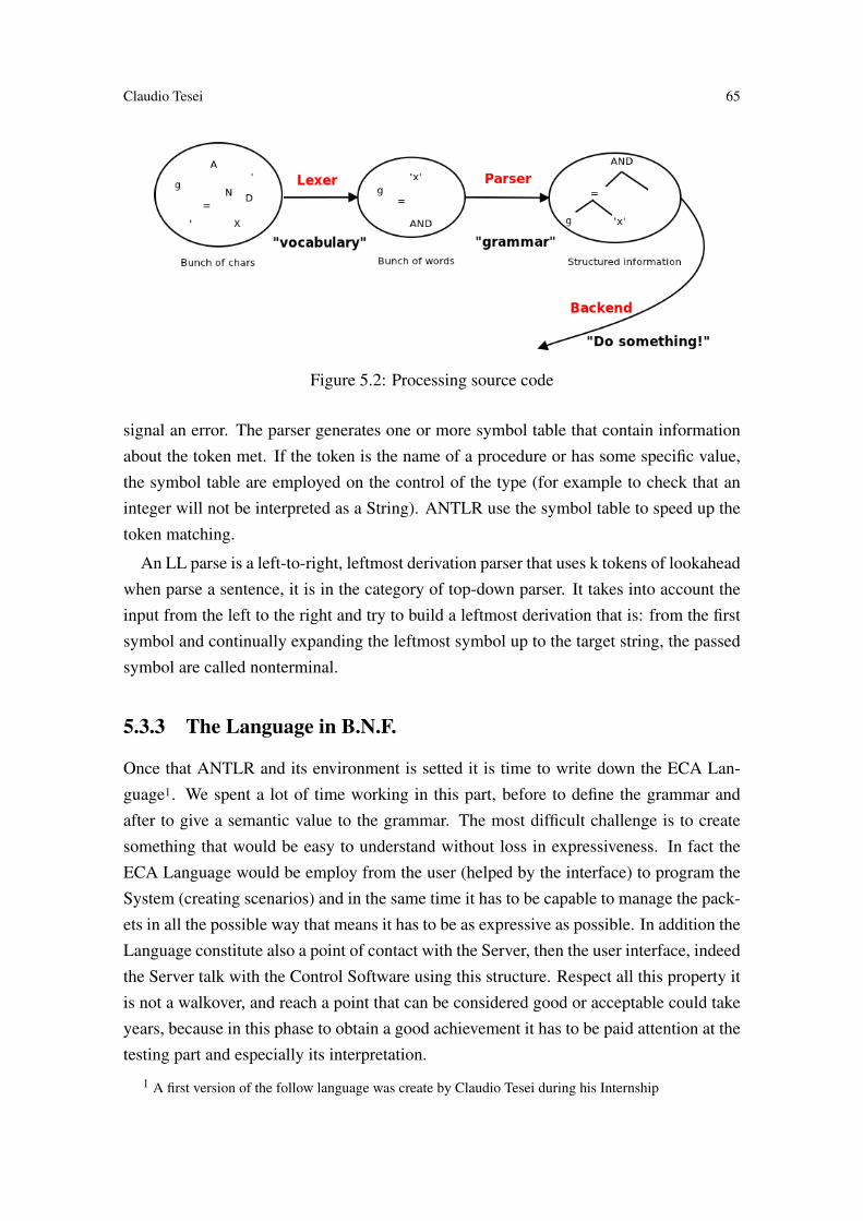
Claudio Tesei 65
Figure 5.2: Processing source code
signal an error. The parser generates one or more symbol table that contain informationabout the token met. If the token is the name of a procedure or has some specific value,the symbol table are employed on the control of the type (for example to check that aninteger will not be interpreted as a String). ANTLR use the symbol table to speed up thetoken matching.
An LL parse is a left-to-right, leftmost derivation parser that uses k tokens of lookaheadwhen parse a sentence, it is in the category of top-down parser. It takes into account theinput from the left to the right and try to build a leftmost derivation that is: from the firstsymbol and continually expanding the leftmost symbol up to the target string, the passedsymbol are called nonterminal.
5.3.3 The Language in B.N.F.
Once that ANTLR and its environment is setted it is time to write down the ECA Lan-guage1. We spent a lot of time working in this part, before to define the grammar andafter to give a semantic value to the grammar. The most difficult challenge is to createsomething that would be easy to understand without loss in expressiveness. In fact theECA Language would be employ from the user (helped by the interface) to program theSystem (creating scenarios) and in the same time it has to be capable to manage the pack-ets in all the possible way that means it has to be as expressive as possible. In addition theLanguage constitute also a point of contact with the Server, then the user interface, indeedthe Server talk with the Control Software using this structure. Respect all this property itis not a walkover, and reach a point that can be considered good or acceptable could takeyears, because in this phase to obtain a good achievement it has to be paid attention at thetesting part and especially its interpretation.
1 A first version of the follow language was create by Claudio Tesei during his Internship

66 Rule Based Control System for Home Automation
To leave no doubt in the reader, beneath there are some example about what the lan-guage should be capable to say:
"When the temperature falls below 16 degrees and it is later than 11pm but earlier than8am turn on the heating at 20 degree"
"When the power consumption has reach 3000 Watt turn off the wall plug2"
"Turn on light1"
As explained in the precedent paragraph the grammar will be composed from specifickey-word, identifier, symbol, operators and structures. :hprogi ::= ‘rule’ hrulei hSEMIi
| ‘define’ hdefinei hSEMIi| ‘delete’ hdeletei hSEMIi| ‘modify’ hmodifyi hSEMIi
hdeletei ::= hIDEihmodifyi ::= hIDEi ‘value’ hINTEGERihdefinei ::= hIDEi ‘:=’ hPACKAGEi hREALNAMEi ‘where’ hbool_expihrulei ::= hIDEi ‘:= when’ hbool_expi ‘then’ = hcommandi (‘else’
hcommandi )?
hcommand:i ::= ‘{’ hIDEi ‘=’ hbool_expi hSEMIi ‘}’
hbool_expi ::= hint_expi (hOPBOOLi hint_expi| hOPRELi| hNOTi hint_expi
hint_expi ::= hsumi (hPLUSi hsumi| hMINUSi hsumi )*
hsumi ::= hfacti (hMULi hfacti| hDIVi hfacti| hMODi hfacti )*
hfacti ::= ‘(’ hint_expi ‘)’| hIDEi| hINTEGERi| hBOOLEANi ;
hPLUSi ::= ‘+’
hMINUSi ::= ‘-’
hMULi ::= ‘*
’
hDIVi ::= ‘/’

Claudio Tesei 67
hMODi ::= ‘%’
hOPBOOLi ::= ‘&&’ | ‘||’
hOPRELi ::= ‘<’ | ‘>’ | ‘<=’ | ‘>=’ | ‘==’ | ‘<>’
hNOTi ::= ‘!’
hTYPEi ::= ‘integer’ | ‘boolean’
hVERSUSi ::= ‘read’ | ‘write’ | ‘virtual’
hBOOLEANi ::= ‘true’ | ‘false’
hINTEGERi ::= ‘0’..‘9’+
hIDEi ::= (‘a’..‘z’|‘A’..‘Z’|‘_’)* (INTEGER)*
hPACKAGEi ::= IDE
hREALNAMEi ::= IDE
hSEMIi ::= ‘;’
hPOINTi ::= ‘,’
Using this grammar we can write again the previous "phrases", that became:
"rule heating := when temp<16 && (time>23 or time<8) then heating = 20;"
"define PC := none virtual value wallp1 + wallp2 + wallp3 + wallp4;"2
"rule monitor := when PC >= 3000 then wallp2 = off;
"modify light1 = on;"
Actually the language has a good expressiveness it is not so easy to understand, indeedan interface that simplifies the "talking" with the CSW it is required and will be alwaysrequired. In the actual state as is possible to note reading the MSc thesis of DavideAngelici the only "phrase" that the user has to write it is to enter is a rule, the others like"define", "modify", "delete" are generated automatically by the interface that let to theuser just the filling of some text field or just press a button.
5.4 Overview of the components and their requirements
The CSW would perform different roles than just provide an ECA Rules Engine. Thewhole software is composed from 4 part, the core of course is the ECA part but the other3 are still important, they provide communication with the DataBase, the Server and thePackage.
In the Figure?? are described the 4 components of the CSW: Server Communicator,Package Communicator, DataBase Communicator and the Event Condition Action Rules
2 The explanation of the virtual variable is in 6.8.1.1 Variable
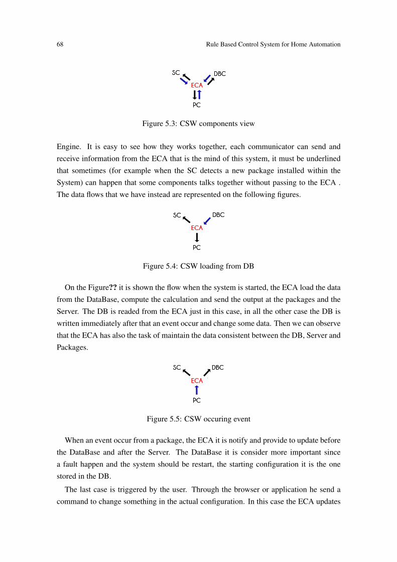
68 Rule Based Control System for Home Automation
Figure 5.3: CSW components view
Engine. It is easy to see how they works together, each communicator can send andreceive information from the ECA that is the mind of this system, it must be underlinedthat sometimes (for example when the SC detects a new package installed within theSystem) can happen that some components talks together without passing to the ECA .The data flows that we have instead are represented on the following figures.
Figure 5.4: CSW loading from DB
On the Figure?? it is shown the flow when the system is started, the ECA load the datafrom the DataBase, compute the calculation and send the output at the packages and theServer. The DB is readed from the ECA just in this case, in all the other case the DB iswritten immediately after that an event occur and change some data. Then we can observethat the ECA has also the task of maintain the data consistent between the DB, Server andPackages.
Figure 5.5: CSW occuring event
When an event occur from a package, the ECA it is notify and provide to update beforethe DataBase and after the Server. The DataBase it is consider more important sincea fault happen and the system should be restart, the starting configuration it is the onestored in the DB.
The last case is triggered by the user. Through the browser or application he send acommand to change something in the actual configuration. In this case the ECA updates

Claudio Tesei 69
Figure 5.6: CSW message from Server
before the packages rather than the DataBase, this is preferred because we want a reactivesystem.
5.5 Server Communicator
To send the message between the Server and the CSW we opt to use a socket. The CSWis written in Java and the communicator part on the Server is written in PHP and bothare in the same OS, then there was differents way to communicate: pipe, FIFO, throughthe DB. In addition to, every OS has a loopback interface, therefore it possible also usea socket. The reasons behind this choice are simple: the sockets are easy to implement,are bidirectional, have a good performance and the feature that is more attractive for usis the possibility to communicate inside a network. Thought a change of the architecturewhere the CSW it is brought out in a different hardware from the Server, a socket wouldbe perfect to the communication. The Server Communicator it is always waiting fora message coming from the server reading constantly the InputStreamReader, barely amessage come it send the data to the ECA engine and wait for an answer that will beforwarded to the Server. Instead from another point of view, the SC provide a methodused by the ECA engine to send data directly at the Server. For example when a newpackage is detected, the engine will send the information about that packet to the Serverthat will just notify the user and through a guided walkthrough will furnish to him an easyway to define the new package in the System.This method take as input just the Stringto forward to the Server. Of course the SC is not the main component of the CSW butdespite its easy implementation its role is very important.
5.6 DataBase Communicator
As each respectable Domotic System also Kaalisy Domotic has its own Database wherestore the data about the user, the environment and the system. What concern the CSWin the Database are just two table Variables and Rule (to a better explanation of the DBsee the thesis of Davide Angelici), the CSW must keep updated this table according with

70 Rule Based Control System for Home Automation
the wishes of the user and especially with the values of the actuator and sensor (whichare precisely our variable in the DB). To communicate with MySQL, that is the DBMSinstalled on the Central Unit as we saw in the chapter 5, we make use of JDBC JavaDataBase Connectivity[?]. It actually is a an API from Oracle Corporation that providean interface for querying and updating data in a Database. Therefore, we use the DCclass as an Interface to reading and writing from the Database not only but especially forthe engine. It provide different methods to write, read, delete and modify a variable andwrite, read and delete a rule. The use of this class could have been avoid just coding aconnection with the Database directly from the engine and the other part of the CSW thatuse the DB, instead we decided to create a class first for the clarity of the code and second,as before, because if a change of DBMS happened will be sufficient change the connectorin this class to solve the problem.
Figure 5.7: Central Unit Software view
5.7 Package Communicator
Send a message to the packages it is a bit more complicated than send it at the Databaseor the Server. In the chapter 5 was introduced the Speaker, a Software in C++ that allowthe CSW to communicate through a transceiver using the SPI. As shown also the Speaker

Claudio Tesei 71
is locate within the Central Unit and even for it can be done the same considerationsmade out to the SC. In fact due to the same reason also in this class we use the socket tocommunicate with the Speaker. Aside this, there is a more complex part that is intrinsic tothe message, because the Speaker will just forwards the String sent from the PC, it has alsothe task to format the message properly to made it understandable from the package. Thenthe PC has to traduce the message according with the communication protocol used by thepackages.3 Furthermore another task is been assigned to the PC, detect the new packagesand signal it to the ECA Engine, this feature is deepened on the follow paragraph. ThePackage Communicator is always listening for a message from the packages, because ifsome sensors change its value the engine should promptly warned. Finally it provide somemethod to allow the ECA Engine to communicate with the packet, for example when acondition in a rule became true, it is duty of the engine make sure that the action will beperformed.
5.7.1 Auto-installation
When a package is inserted for the first time, it will send a message content its packagenumber (univocal for all the packages) and type to the Package Communicator whichimmediately will check whether this packed exist or no in the DB, in both case it have torespond with a "Welcome" message. Afterwards and notify the SC (skipping the ECA inthis case) of this new package. The Server Communicator will notify the Server whichwill provide an interface to let the user set the package. Once that the user has finishedto set up the package it is time to the system to define a new variable and let know at theuser that all went well.
Figure 5.8: Auto-installation sequence diagram
Above it is shown an example of auto-installation of a Lumus Package. The user settlein a new Lumus Package at home. The package is detected and the system follow the
3 A strength protocol has to be implemented yet, until now we use a simple protocol that allow us tocommunicate with the packages.

72 Rule Based Control System for Home Automation
procedure as exposed, supposing that the user call the variable light1 and set it on, thegenerated String from the UI that the ECA Rules will receive would be:" define light1 :=0234 1 value 1;". At this point the engine do what it have to do and send the command tothe PC, that will traduce it thanks to the help of the DB to obtain the package and variablenumber, sequentially the Package Communicator will send the command to the packageand will wait until a confirm message arrive. If the "OK" message does not arrive meansthat something it went wrong so the PC will send again the command message until ananswer arrive or the time expires (an time limit has set by default).
5.8 Kaalisy Rules Engine
Everything it is clear now, except a small part, how work the Rules Engine? Well, it istime to reveal the secrets of this mystic engine. This paragraph is focused on how the ECAengine play his role inside the Control Software. We understand how and from whom ittakes the input, the mechanism concealed behind a command, how is administrate themessage traffic, but how it transform the String: "modify light1 = 1" in a command todeliver?
5.8.1 Overview of the component
Even this time it is necessary understand the environment that rotate behind the engine,by doing so it will be possible pass at the next paragraph and understand the semanticvalue of each structure in the language.
Figure 5.9: ECA Rules Engine components view
As can be seen from the Figure?? the main structures are two Hashmap that contain thelink to the Variable and the Rule. The last one it is not a Java object but is a Thread that

Claudio Tesei 73
is running the Rule. A lot of structures could have been used instead of the HashMap, butwe considered that for our purpose store a Variable or Rule based on the key that can evenbe used to retrieve the item later it is just what we need. In this phase the point is to useless resources when it is possible, running on the Raspberry Pi the CSW has to be reallylight if we want to have a good performance. For this reasons even the method employedto pull out an item from a data structure (an hashmap in our case) it is significant.
Variable
We know that a variable in the engine correspond to an actuator or a sensor in the domoticsystem, then we needed to insert values that can be used to represent any type of actuatoror sensor. To address they there were no problem because each packages has an univocalidentification String and each actuator or sensor has an univocal "realname" inside thepackage. Represent the status instead was not so easy, in a first version we had generalizedand use boolean and integer value. Boolean to all the variable that can be turn on or offand integer to all the other. This way to storage the status works pretty well but becamemore complicated during the defining phase and means also another value to store andpass during the call aimed to identify the type. Due to this in the following version everystatus it is represented with an integer that will be decodified in a boolean or an integerinside the package.
Figure 5.10: Variable Class
To distinguish between actuator and sensor, we used two String "read" and "write".Actually there is also a third type of variable, it ha versus "virtual" means that does not

74 Rule Based Control System for Home Automation
physically exists in the system, in fact it is used to express value that does not came froma package. An example may explain better which is its role."define PC := none virtual value wallp1 + wallp2 + wallp3 + wallp4;" In this case thevariable PC does not represent an actuator or a sensor but the value of four variables,so it can be defined as "virtual". In the Figure?? it is shown also another member, anArrayList of String called rules, that list contain the name of the rules in which the variableappears in the condition. Another possibility to achieve the same goal (link the rules withthe variable present in their conditions) could have been insert a list of the name of thevariable inside the class rule, at first sight seems even more elegant as solution, but furtherit will be clear the reasons of that choice.
Rule
The rule is the most complex concept in this document, at this point the reader should haveunderstand the major feature of the rule, but we have just mentioned at the beginningof this subchapter about its implementation. As we know a rule must to be reactive,as soon as the condition of the rule changes, the system has to perform the consequentactions.
Figure 5.11: Rule Class
In the Figure?? it is shown that the rules are represented as a Thread, this is not com-pletely correct, the rules contained on the HashMap are Objects of the class shown inFigure?? that have a Thread as member. Of course that Object can be interpreted as aThread, but was necessary to be clear underline this difference.4 Returning to what wassaid before, Thread are optimum to our purpose. We can start a thread for each rule, andmake a cycle inside it to check the condition of the rule, whereas the condition is true orfalse it will decide which action perform. Such a method is easy to do, but it is prettyobvious that wastes a huge quantity of resources. Consider that the system has to run 20
4 Since the call stop has been deprecated was impossible put directly the Thread on the Hashmap andall this was necessary.
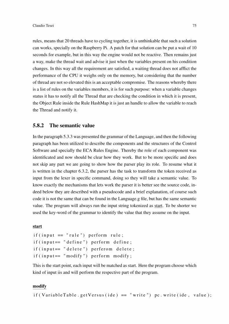
Claudio Tesei 75
rules, means that 20 threads have to cycling together, it is unthinkable that such a solutioncan works, specially on the Raspberry Pi. A patch for that solution can be put a wait of 10seconds for example, but in this way the engine would not be reactive. Then remains justa way, make the thread wait and advise it just when the variables present on his conditionchanges. In this way all the requirement are satisfied, a waiting thread does not afflict theperformance of the CPU it weighs only on the memory, but considering that the numberof thread are not so elevated this is an acceptable compromise. The reasons whereby thereis a list of rules on the variables members, it is for such purpose: when a variable changesstatus it has to notify all the Thread that are checking the condition in which it is present,the Object Rule inside the Rule HashMap it is just an handle to allow the variable to reachthe Thread and notify it.
5.8.2 The semantic value
In the paragraph 5.3.3 was presented the grammar of the Language, and then the followingparagraph has been utilized to describe the components and the structures of the ControlSoftware and specially the ECA Rules Engine. Thereby the role of each component wasidentificated and now should be clear how they work. But to be more specific and doesnot skip any part we are going to show how the parser play its role. To resume what itis written in the chapter 6.3.2, the parser has the task to transform the token received asinput from the lexer in specific command, doing so they will take a semantic value. Toknow exactly the mechanisms that lets work the parser it is better see the source code, in-deed below they are described with a pseudocode and a brief explanation, of course suchcode it is not the same that can be found in the Language.g file, but has the same semanticvalue. The program will always run the input string tokenized as start. To be shorter weused the key-word of the grammar to identify the value that they assume on the input.
start
i f ( i n p u t == " r u l e " ) pe r fo rm r u l e ;i f ( i n p u t == " d e f i n e " ) pe r fo rm d e f i n e ;i f ( i n p u t == " d e l e t e " ) p e r f e r o m d e l e t e ;i f ( i n p u t == " modify " ) pe r fo rm modify ;
This is the start point, each input will be matched as start. Here the program choose whichkind of input iis and will perform the respective part of the program.
modify
i f ( V a r i a b l e T a b l e . g e t V e r s u s ( i d e ) == " w r i t e " ) pc . w r i t e ( ide , v a l u e ) ;

76 Rule Based Control System for Home Automation
V a r a i a b l e T a b l e . modify ( ide , v a l u e ) ;V a r i a b l e T a b l e . n o t i f y R u l e s ( i d e ) ;dbc . w r i t e ( ide , v a l u e ) ;s c . w r i t e ( "OK" ) ;
As we can see from The Language the input string modify has two fields to fill: thename of the variable to modify and the value of the status which has to assume. Then,the program according with the requirements, check if that variable is an actuator. Ina positive case it will first update the value of that variable in the Package through thePackage Communicator, otherwise it will start changing the field value of that variablein the Variable HashMap. Now that the value of a variable is change it must notify allthe Rules in which it appears on the condition. At the end will be updated the Databasethrough the Database communicator and the Server Communicator will indicate at the UIthat everything went well.
delete
i f ( Ru leTab le . c o n t a i n ( i d e ) {Ru leTab le . k i l l ( i d e ) ;Ru leTab le . d e l e t e ( i d e ) ;V a r i a b l e T a b l e . d e l e t e R u l e s f r o m V a r i a b l e ( i d e ) ; }
i f ( V a r i a b l e T a b l e . c o n t a i n ( i d e ) ) {i f ( V a r i a b l e T a b l e . h a s R u l e s ( i d e ) ) {
sc . w r i t e ( " e r r o r " ) }e l s e {
V a r i a b l e T a b l e . d e l e t e ( i d e ) ; } }dbc . d e l e t e ( i d e ) ;s c . w r i t e ( "OK" ) ;
If the input was a delete command it contain just the name of the rule or variable to can-cel, once established whether it is a rule or a variable, it will take two different actions: -inthe case it is a rule name, the thread that is running that rule will be killed, its entry con-taining the handler and the identifier in the HashMap will be delete and also the referencespresent in the variable which was present in its condition will be delete. -in the case it is avariable name, first it must be checked if this variable is in any rule condition, to preventa disaster, if is not the program will proceed to delete the variable from the Variable Table.
define
V a r i a b l e T a b l e . i n s e r t ( ide , pack , rea lname , v a l u e ) ;
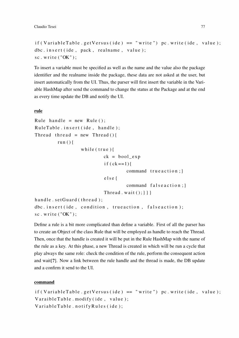
Claudio Tesei 77
i f ( V a r i a b l e T a b l e . g e t V e r s u s ( i d e ) == " w r i t e " ) pc . w r i t e ( ide , v a l u e ) ;dbc . i n s e r t ( ide , pack , rea lname , v a l u e ) ;s c . w r i t e ( "OK" ) ;
To insert a variable must be specified as well as the name and the value also the packageidentifier and the realname inside the package, these data are not asked at the user, butinsert automatically from the UI. Thus, the parser will first insert the variable in the Vari-able HashMap after send the command to change the status at the Package and at the endas every time update the DB and notify the UI.
rule
Rule h a n d l e = new Rule ( ) ;Ru leTab le . i n s e r t ( ide , h a n d l e ) ;Thread t h r e a d = new Thread ( ) {
run ( ) {w h i l e ( t r u e ) {
ck = boo l_expi f ( ck ==1){
command t r u e a c t i o n ; }e l s e {
command f a l s e a c t i o n ; }Thread . w a i t ( ) ; } } }
h a n d l e . s e t G u a r d ( t h r e a d ) ;dbc . i n s e r t ( ide , c o n d i t i o n , t r u e a c t i o n , f a l s e a c t i o n ) ;s c . w r i t e ( "OK" ) ;
Define a rule is a bit more complicated than define a variable. First of all the parser hasto create an Object of the class Rule that will be employed as handle to reach the Thread.Then, once that the handle is created it will be put in the Rule HashMap with the name ofthe rule as a key. At this phase, a new Thread is created in which will be run a cycle thatplay always the same role: check the condition of the rule, perform the consequent actionand wait[?]. Now a link between the rule handle and the thread is made, the DB updateand a confirm it send to the UI.
command
i f ( V a r i a b l e T a b l e . g e t V e r s u s ( i d e ) == " w r i t e " ) pc . w r i t e ( ide , v a l u e ) ;V a r a i b l e T a b l e . modify ( ide , v a l u e ) ;V a r i a b l e T a b l e . n o t i f y R u l e s ( i d e ) ;

78 Rule Based Control System for Home Automation
dbc . modify ( ide , v a l u e ) ;s c . w r i t e ( "OK" ) ;
Perform an action means change the state of one or more variables, then in the input mustbe specified the name of the variable and the value which they have to assume. As eachtime that the program need to change a variable, before check the type to know if it isnecessary change its status in the package. After, it will update the value in the VariableHashMap, notify the rule, update the Database and a confirm it send to the UI.
bool_exp
r e t u r n v a l u e _ o f _ e x p r e s s i o n ;
To receive the value of the expressions, the program effect several call depending from thecomplexity of the expression, it is here that the variable "ide" present on the expressiontake a value. Observing the language starting from bool_exp, it is easy understand theflow that transform an expression from a string to an integer value.

79
Chapter 6
Conclusion
Certainly, the reader now is so passionate at the reading that has not noticed that thethesis is finished. Maybe he was expecting other chapters, in which he would have likedto see the implementation of all the packages, the testing phases and the reaction fromthe market when this new product will be introduced, but unfortunately, beautiful thingsalways come to an end. I began this thesis claiming that the subject of the document was toevolve an Idea to an enterprise; maybe, in the introduction, whoever was reading thoughtthat it was just an arrogant exclamation, but I hope that along the lecture he changed hismind. Through the chapters, it is possible to see which are the basis and the referencesthat allow us to say:" We can make the Domotic Easy and Low Cost to everyone". In theBusiness Plan we verified that our Idea is innovative and competitive compared with theother products already present in the market. Obviously, not all that glitters is gold: weacknowledge the presence of strong competitors, and especially we have discovered theexistence of a similar product overseas (SmartThings, Revolv). Then, taking into accountthe considerations made in the Business Plan, we pass to the design of the product. Bythe mere reading of this document, designing the structure of the system may appear aneasy challenge, but it is not so; also if we already knew all the requirements, writingdown the found solution, and concretizing an Idea, is never an easy work. However,the most interesting part is always the implementation, and it is largely described in thisthesis. Through what we wrote the reader should achieve an appropriate knowledge ofthe system, enough to be able to develop the product by himself. We know that the thesislacks the testing phase part, but sadly we have not developed other packages yet; we leftthe testing phase to be a future work. This document summarizes a part of the work doneso far, not only with the goal of writing a thesis but, with the aim of using what we learnedduring our studies to create our future. Lot of efforts has been done until now to reachthis step, and for sure we will face with many other obstacles during the route addressed
80 Rule Based Control System for Home Automation
to build an enterprise, but this does not discourage us, we will go forward as we alwayshave done.
6.1 Future work
We wrote about what we have done so far, but the route we intent to do is still long andfull of pitfalls. In this section is described the pending work that we have to do to developthis product, and some improvements that can be done.
6.1.1 Improvements
Some parts have not been developed as written in the Design Documentation, becausethey were not in line with the topic of this thesis, and, due to the lack of time, we havegiven priority to other parts; however, this does not mean that we will skip them.
Communication protocolWe developed a protocol that allow the communication between the packages, but doesnot furnish at all a security layer. The protocol utilized can be easily hacked with a MITM(Man in the Middle) technique, for which it is sufficient to masquerade as another packageto be capable to communicate with the system. Due to this reason we want to implementa security layer in the communication protocol.
Group of variablesIn the actual state of the system, if the user want to use a variable to describe the behaviourof a group of variables, he have to do a tedious work with the rules. What we want is tosimplify this feature with a new command, that should be capable to express a similarconcept:" When light_group is turned off, turn off all the light".
6.1.2 Developing
Talking about software and hardware, not everything has been developed: some partshave to be designed and implemented yet. This phase will require a consistent amount ofhours of hard work, but has to be done to be inline with what we want to produce.
PackagesUntil now we developed just the Central Unit, the other packages have been omitted; theirdesign and development will not be as complex as it was for the Central Unit, however

Claudio Tesei 81
it is an important work to do as soon as possible. Actually we already have a prototypeof some packages but it is really raw and we need to redesign it to make it ready for themarket.
Checking the presence of inconsistent ECA rulesProbably the reader has noticed that the usage of the rules can create several problems. Ifthe user does not care about the correctness of the rules inserted into the system, an incon-sistency between that rules may appear. To be more concrete, it is sufficient to imagine arule that opens a door when a light is switched on, and another rule that switched off thelight when such door is opened: obviously it is impossible to switch on the light due toan inconsistency. Even greater problems can arise: if the rules inserted are not correct, acycle can be formed. To avoid this sort of problems, we need to develop a checker, thatcontrol the correctness of the rule inserted, by comparing it with the rules already presentin the system; this is a difficult work, but it is indispensable if we want to create a goodproduct.
6.1.3 Testing
The last phase in which we will go through is the Testing. Before celebrating the accom-plishment of the route, when all the packages will be ready, it will be necessary to doseveral tests. The tests will be focused on stressing the components and put the softwareunder pressure; by doing so, we will discover also the limit of the product. Probably, wewill even let our product be tested by some possible future users, that could represent thetarget category at which we are aiming.
6.2 Future Project
Almost at the end of the projects, programmed to be done for the thesis, we decided toupset our plan, for this reason I decided to insert this section in the conclusion.
6.2.1 The reason
During the writing of the thesis, we really started to go deeply in our project and doingso we noticed different failure in the products and in the Business Plan. We believe that:even if the use of the ECA language provide an optimal ratio expressiveness/complexity,it is better reduce the complexity also if this means reduce the expressiveness. Due tothis reason, we decide to hide the Language layer at the user, and keep it active as a
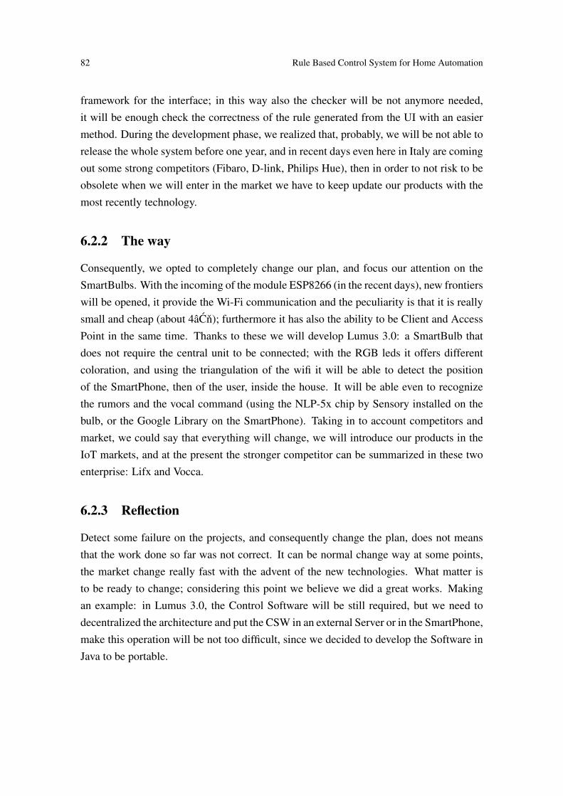
82 Rule Based Control System for Home Automation
framework for the interface; in this way also the checker will be not anymore needed,it will be enough check the correctness of the rule generated from the UI with an easiermethod. During the development phase, we realized that, probably, we will be not able torelease the whole system before one year, and in recent days even here in Italy are comingout some strong competitors (Fibaro, D-link, Philips Hue), then in order to not risk to beobsolete when we will enter in the market we have to keep update our products with themost recently technology.
6.2.2 The way
Consequently, we opted to completely change our plan, and focus our attention on theSmartBulbs. With the incoming of the module ESP8266 (in the recent days), new frontierswill be opened, it provide the Wi-Fi communication and the peculiarity is that it is reallysmall and cheap (about 4âCn); furthermore it has also the ability to be Client and AccessPoint in the same time. Thanks to these we will develop Lumus 3.0: a SmartBulb thatdoes not require the central unit to be connected; with the RGB leds it offers differentcoloration, and using the triangulation of the wifi it will be able to detect the positionof the SmartPhone, then of the user, inside the house. It will be able even to recognizethe rumors and the vocal command (using the NLP-5x chip by Sensory installed on thebulb, or the Google Library on the SmartPhone). Taking in to account competitors andmarket, we could say that everything will change, we will introduce our products in theIoT markets, and at the present the stronger competitor can be summarized in these twoenterprise: Lifx and Vocca.
6.2.3 Reflection
Detect some failure on the projects, and consequently change the plan, does not meansthat the work done so far was not correct. It can be normal change way at some points,the market change really fast with the advent of the new technologies. What matter isto be ready to change; considering this point we believe we did a great works. Makingan example: in Lumus 3.0, the Control Software will be still required, but we need todecentralized the architecture and put the CSW in an external Server or in the SmartPhone,make this operation will be not too difficult, since we decided to develop the Software inJava to be portable.

83
Appendices


Claudio Tesei 85
Figure 1: Expected Revenue by product
Figure 2: Plan of marketing costs
Figure 3: Investement Plan

86 Rule Based Control System for Home Automation
Figure 4: Plan of staff costs
Figure 5: Income Statment
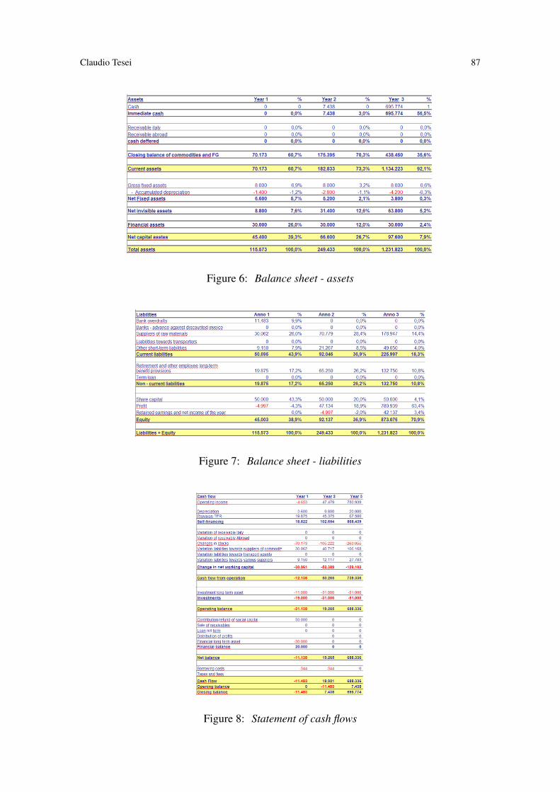
Claudio Tesei 87
Figure 6: Balance sheet - assets
Figure 7: Balance sheet - liabilities
Figure 8: Statement of cash flows

88 Rule Based Control System for Home Automation
Figure 9: Ratios


School of Computer Science
Reykjavík University
Menntavegi 1
101 Reykjavík, Iceland
Tel. +354 599 6200
Fax +354 599 6201
www.reykjavikuniversity.is
ISSN 1670-8539
School of Computer Science
University of Camerino
Piazza Cavour 19 / f
62032 Camerino(MC), Italy
P.IVA: 00291660439
Tel. 800 054 000
Fax 800 054 000
www.unicam.it