s. bin journal ocean engineering science
TRANSCRIPT
Available online at www.sciencedirect.com
Journal of Ocean Engineering and Science 1 (2016) 167–179 www.elsevier.com/locate/joes
An analytical method to assess the damage and predict the residual strength of a ship in a shoal grounding accident scenario
Sun Bin
a , Hu Zhiqiang
a , ∗, Wang Jin
a , b , Yu Zhaolong
c
a State Key Lab of Ocean Engineering, Shanghai Jiao Tong University, Shanghai, China b COTEC USA, Houston, USA
c Dept. of Marine Technology, Norwegian University of Science and Technology, Trondheim, Norway
Received 22 May 2015; received in revised form 19 August 2015; accepted 18 September 2015 Available online 14 March 2016
Abstract
In this paper, a simplified analytical method used to predict the residual ultimate strength of a ship hull after a shoal grounding accident is proposed. Shoal grounding accidents always lead to severe denting, though not tearing, of the ship bottom structure, which may threaten the global hull girder resistance and result in even worse consequences, such as hull collapse. Here, the degree of damage of the bottom
structure is predicted by a series of analytical methods based on the plastic-elastic deformation mechanism. The energy dissipation of a ship bottom structure is obtained from individual components to determine the sliding distance of the seabed obstruction. Then, a new approach to assess the residual strength of the damaged ship subjected to shoal grounding is proposed based on the improved Smith’s method. This analytical method is verified by comparing the results of the proposed method and those generated by numerical simulation using the software ABAQUS. The proposed analytical method can be used to assess the safety of a ship with a double bottom during its design phase and predict the residual ultimate strength of a ship after a shoal grounding accident occurs. © 2016 Shanghai Jiaotong University. Published by Elsevier B.V. This is an open access article under the CC BY-NC-ND license ( http://creativecommons.org/licenses/by-nc-nd/4.0/ ).
Keywords: Shoal grounding; Residual strength; Simplified analytical method; Numerical simulation; Damage analysis.
1
t
s
v
n
t
i
p
h
a
s
r
c
i
p
d
p
i
j
s
o
(
a
m
a
i
p
h2(
. Introduction
Ship grounding over a seabed obstruction may lead to po-ential consequences, such as significant economic loss andevere environmental pollution, and ultimately may sink theessel and result in deaths. In the 21st century, although sig-ificant progress has been made in improving navigationalools, severe accidents due to grounding still occur period-cally. Accidents draw public interest and highlight the im-ortance of making reliable assessments of damaged vessels’ull strength to enhance sailing safety.
During the preliminary design stage or after a groundingccident occurs, it is essential to predict the residual ultimatetrength of the damaged ship. To accomplish this task, a moreational design procedure and calculation tools with high effi-
∗ Corresponding author. E-mail address: [email protected] (H. Zhiqiang).
v
s
ttp://dx.doi.org/10.1016/j.joes.2016.03.007 468-0133/© 2016 Shanghai Jiaotong University. Published by Elsevier B.V. This http://creativecommons.org/licenses/by-nc-nd/4.0/ ).
iency are required. Amdahl [1] proposed the following fourtems, which are considered elementary in a rational designrocedure and are generally followed in this thesis: scenarioefinition, global and local structural performance calculation,ost-accident evaluation and acceptance criteria. The prevail-ng approaches to analyze the response of ship structures sub-ected to grounding and to assess the ultimate strength of ahip are typically divided into four categories: empirical meth-ds, model-scale tests, the non-linear finite element methodNLFEM), and simplified analytical methods. The simplifiednalytical method is an improvement over currently availableethods because it is mathematically tractable, has reason-
ble accuracy, is cost and time effective, and most notably,s superior in providing insight into the governing physicalrocesses.
The deformation mechanics of ship bottom structures in-olved in grounding accidents vary due to the variety ofeabed obstructions. There are three major types of seabed
is an open access article under the CC BY-NC-ND license
168 S. Bin et al. / Journal of Ocean Engineering and Science 1 (2016) 167–179
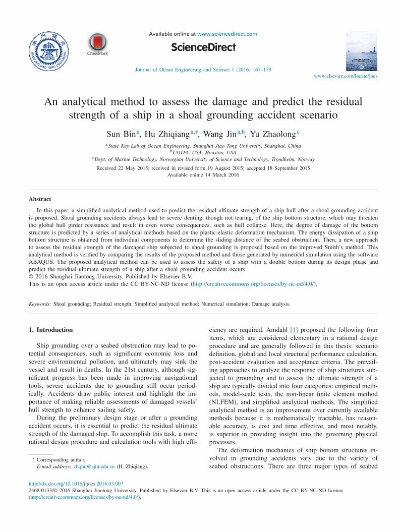
Fig. 1. Seabed topology with reference to bottom sizes: (a) rock; (b) reef; (c) shoal.
o
s
s
t
a
e
c
g
o
[
c
a
p
g
i
p
g
o
s
S
i
A
2a
s
[
s
n
a
[
i
s
p
t
l
2s
d
t
i
d
c
t
s
s
a
E
indenters as defined by Alsos and Amdahl [2] , namely ‘rock’,‘reef’ and ‘shoal’ (see Fig. 1 ). A great number of studies havealready focused on ship groundings over rock-type seabed ob-structions, which primarily tear the bottom plate, resulting incompartment flooding. However, it has been recognized thatship grounding over a flat seabed obstruction with a largecontact surface, namely shoal grounding, is more common inpractice by Amdahl [1] and Wang ( [3] , 2002). In this situa-tion, denting rather than tearing is the more likely deformationmode for the bottom plating; as a result, the global hull bend-ing capacity of the ship is at risk as presented by Pedersen[5] and Alsos [6] , which may eventually trigger collapse ofthe hull girder by bending or shearing and cause hazardousconsequences as presented by Hong and Amdahl [7] . Thereby,an analysis of the ship ultimate strength after shoal groundingis of crucial importance.
To evaluate the resistance and energy dissipation of a ship’sbottom structure during shoal grounding scenarios, Hong andAmdahl [7] proposed an analytical method that assembles var-ious simplified analytical formulae for individual structuralcomponents, including a sliding deformation model of thelongitudinal girders, denting and crushing models of the trans-verse members and a denting model of the bottom plating. Inthe method, the attached stiffeners are taken into account us-ing the smearing thickness approach proposed by Paik andLee [8] . The method has been challenged by Hu and Amdahl[9] , Hu et al. [10] and Yu et al. [11] ; it has been found that thesmearing thickness method underestimates the role of stiffen-ers during a shoal grounding accident. In this context, Yuand Hu [11–13] made several predictions on the performanceof stiffeners during a ship shoal grounding scenario. Theseproposed theoretical approaches provide comprehensive de-scriptions of the deformation modes, energy dissipation andstructural resistance of stiffeners attached to the bottom floorplating, longitudinal girder and outer bottom plate. The afore-mentioned methods have considered all the structural compo-nents of the bottom structure that resist structural deformationduring shoal grounding. However, the residual strength of thecomponents has not been considered.
The simplified progressive collapse method, also known asthe Smith method [15] , is a widely known approach to pre-dict the ultimate strength behavior of a ship hull girder. Theapproach has been shown to provide accurate results by ISSCconference committee [16] and Gordo and Guedes Soares[17] . The Smith method can also assess the residual strengthof a damaged hull girder; however, the limited assumptions
f the method mean that only a relatively simplistic repre-entation of the damaged area can be modeled. Furthermore,tructures damaged from collision or grounding are knowno possess residual strengths with a load-carrying capabilitys presented by Liu et al. [18] and Paik et al. [19] ; how-ver, in the conventional Smith method, damaged elementsannot withstand any further load, and thus the method disre-ards damaged elements in the progressive collapse analysisf a damaged hull girder such as Gordo and Guedes Soares20] and Wang et al. [3] . Thus, the hull girder deterministicapacity is always underestimated as presented by Wang etl. [4] and Hussein and Guedes Soares [21] .
In this paper, a simplified analytical method is proposed toredict the residual ultimate strength of a ship after a shoalrounding accident. Three typical shoal grounding scenar-os are defined. A combination of previous studies that haveredicted the responses of bottom structures during a shoalrounding accident is validated, and the residual strengthf damaged structures is evaluated; certain reasonable as-umptions are proposed. In particular, the assumptions of themith method are improved. The proposed simplified analyt-
cal method is then verified by numerical simulation usingBAQUS code.
. Response of bottom structures and structural damage nalysis
A bottom structure is generally considered to be an as-embly of plated structures and stiffeners. Hong and Amdahl7] proposed a simplified analytical method to predict the re-ponses of three plated structures: transverse floors, longitudi-al girders and outer bottom plating. Hereafter, the stiffenersttached to these structures were considered by Yu and Hu11,13,14] . The seabed obstruction is represented by a rigidndenter with a flat contact surface and a trapezoidal cross-ection, and the responses of the bottom can be considerederiodic because of the repetitive arrangement of the struc-ural members.
The simplified analytical methods are described briefly be-ow, and a structural damage analysis is proposed.
.1. Damage analysis of the bottom floor and attached
tiffeners
During a shoal grounding scenario, it is observed that theeformation zone of the transverse floor can be divided intowo parts (see Fig. 2 ). The central part, where the breadths same as that of the indenter, is pushed directly by the in-enter. The side part, which deforms simultaneously with theentral part, is affected by the indenter indirectly. As a result,he energy dissipated by the transverse floor is calculated byumming the computations of the two parts. The energy dis-ipated by the collapse of the central part can be expresseds
floor, central = 4 M 0 _ floor
(2. 58
H
2
t +
(π
2
)2 + πC
)(1)

S. Bin et al. / Journal of Ocean Engineering and Science 1 (2016) 167–179 169
Fig. 2. Transverse floor after horizontal crushing.
Fig. 3. Transverse section of the indenter.
i
E
w
i
p
t
c
o
2
m
b
w
t
o
s
b
A
a
t
F
3
3
Fig. 4. Theoretical models of the floor stiffener (a) D < Ls /2, (b) Ls /2 ≤ D
(Yu and Hu [11] ).
w
p
E
w
ra
p
E
w
E
E
The energy dissipated during the crushing of the side parts as follows:
floor, side =
14
3
πM 0 _ floor b + 29 . 68
N 0 _ floor H
3
b
(2)
here M 0 represents the fully plastic bending moment capac-ty of a plate strip, N 0 is the plastic membrane force of alate strip, C is the half-breadth of the span of the inden-er contact surface (see Fig. 3 ), and H is half of the verticalrushing distance, which is determined by the crushing depthf indenter D . The variable H is expressed as
H = 1 . 0836 D + 0. 0652 (3)
According to the upper-bound theorem, b can be deter-ined by
= 2. 85 H
√
H
t f (4)
here t f is the thickness of the floor plate. It should be notedhat b , in any case, should be larger than the shoulder breadthf the indenter B (refer to Fig. 3 ) and should not exceed thepacing of adjacent longitudinal girders.
The deformation pattern of the stiffeners attached to theottom floor largely depends on the deformation of the floor.ccording to the degree of indentation, two analytical models
re established (see Fig. 4 ), when D is less than Ls /2 ( Ls ishe length of the stiffener), which is the model presented inig. 4 (a), and when D is larger or equal to Ls /2 but less thanLs /4, which is the model presented in Fig. 4 (b). If D exceedsLs /4, the model is the same as that presented in Fig. 4 (b),
here additional energy is assumed to be dissipated throughlastic rolling about hinge B.
When D < Ls /2, the energy dissipation is expressed as
f s =
M 0 _ f s t f s x 1 θ2
sin θ+
M 0 _ f s t f s x 2 (2α − θ ) 2
sin (2α − θ )
+ 2 N 0 _ f s αh f s + 4 M 0 _ f s t f s α (5)
here x 1 and x 2 are the lengths of straight line BC and CD,espectively, θ and α are as shown in Fig. 4 , and t fs and h fs
re the thickness and height of the stiffener, respectively. When Ls/2 ≤ D < 3Ls /4, the energy dissipation is ex-
ressed as
f s =
M 0 _ f s t f s x 1 θ2
sin θ+
M 0 _ f s t f s x 2 (2α − θ +
π2
)2
cos (2α − θ )
+ N 0 _ f s
(2α +
π
2
)h f s + M 0 _ f s t f s (4α + π) (6)
When 3 Ls /4 ≤ D , the additional energy dissipation isritten as
additional = M 0 _ f s t f s (D − D basic ) π (7)
Then, the total energy dissipated is expressed as
f s = E additional + E basic (8)

170 S. Bin et al. / Journal of Ocean Engineering and Science 1 (2016) 167–179
Fig. 5. Longitudinal girder after the sliding process.
Fig. 6. Theoretical model of the longitudinal stiffener (Yu and Hu [13] ).
Fig. 7. Strip beam model (Yu and Hu [13] ).
E
w
c
o
A
h
R
ϕ
w
w
t
t
a
e
E
where D basic is usually set as 3Ls /4 and E basic is the energydissipation at this indentation condition.
In the actual calculation, the analytical method result istypically larger than the actual value, and thus, a reductionfactor λ is introduced:
λ =
{0. 714, D < L s / 2
0. 833 , D ≥ L s / 2
(9)
Once the transverse floors are damaged severely, their rolein supporting the frames will be significantly reduced. As aconsequence, the assumption of the Smith method will nolonger be satisfied, which will be discussed in more detail.
2.2. Damage analysis of the longitudinal girder and its stiffeners
During the shoal grounding scenario, the longitudinalgirder is subjected to a continuous sliding process and iscrushed both vertically and horizontally (see Fig. 5 ). The en-ergy dissipation can be expressed as
E girder = M 0 _ girder πH (1 + 2
√
1 + tan
2 ψ ) · 1 − tan
2 ψ
tan ψ
+
4 N 0 _ girder H
2
√
3
√
1
4
+ tan
2 ψ (10)
where ψ is half of the crushing wave angle of the mechanism,which can be written as
2ψ = 0. 94φ − 0. 0048 φ2 (11)
where φ is the slope angle of the indenter front surface. The damage degree of the longitudinal girder can be cal-
culated by introducing a reduction factor k :
k =
E girder _ 1
E girder _ 2 (12)
where E girder _ 1 is the energy dissipation of the longitudinalgirder at the actual crushing depth and E girder_2 is the energydissipation when the crushing depth is equal to the height ofthe longitudinal girder.
The deformation patterns of the stiffeners attached to thelongitudinal girder during a shoal grounding accident can bedivided into two groups, namely, stiffeners that are fully incontact with the indenter and stiffeners that are indirectly af-fected by the indenter.
For the stiffeners fully in contact with the indenter, thetheoretical model is presented in Fig. 6 . The stiffener ascendsspirally with an angle of inclination γ . The energy dissipationcan be obtained as
ls = M 0 _ gs ϕ + M 1 _ gs L · π
4
+ N 0 _ gs ·(
2Rϕ
cos γ− L
)+ 2 M 0, 2 _ gs h gs Lφ (13)
here M 1 represents the fully plastic tripping or verticalrushing moment, t gs and h gs are the thickness and heightf the stiffener, respectively, L is the length of straight lineB, which is equal to half of the frame spacing, and h is theeight of the arch equal to H /2. R and ϕ are written as
=
L
2
8 h
+
h
2
(14)
= arcsin
(L
2R
)(15)
here R is the radius of arc AB. For stiffeners that do not contact the indenter but deform
ith the longitudinal girders, the energy dissipation from ver-ical crushing is unavailable. The deformation mode conformso the theory of cylindrical bending, and the stiffener is treateds a strip beam (see Fig. 7 ). The energy dissipation can bexpressed as
ls = M 0 _ gs ϕ
′ + M 1 _ gs L · π
4
+ N 0 _ gs · (2R
′ ϕ
′ − L) (16)
S. Bin et al. / Journal of Ocean Engineering and Science 1 (2016) 167–179 171
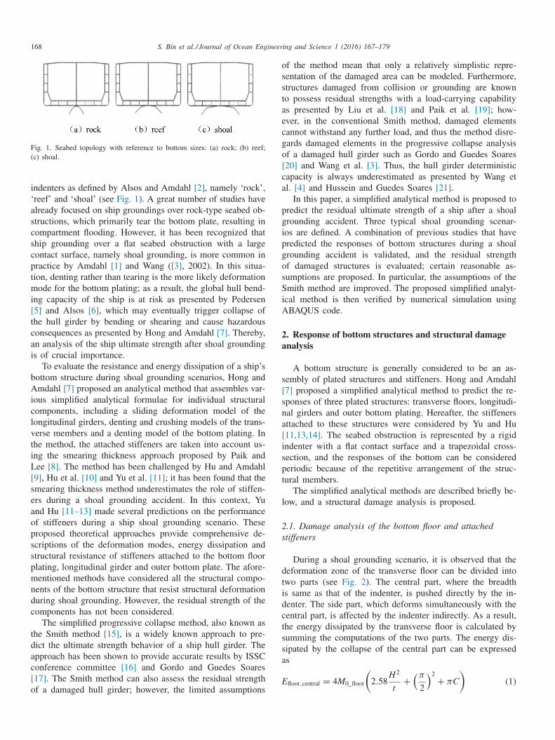
Fig. 8. Theoretical model of the bottom structures.
w
s
h
w
a
r
a
s
w
t
e
t
s
t
i
2
a
i
t
a
s
t
p
p
a
b
d
e
E
w
ua
Fig. 9. Damage model of the bottom plate during sliding.
L
L
f
R
f
b
t
i
s
c
c
a
d
a
f
t
i
o
t
r
d
i
E
w
h
t
u
v
here the transverse extension h is replaced by h’ and sub-tituted into Eqs. (14) and ( 15 ), and h’ is obtained as
′ =
δ2 s
δ2 i
· h (17)
here δi and δs are the vertical distance from the indenternd indirectly deformed stiffener to the top end of the girder,espectively.
The stiffener that is fully in contact with the indenter isssumed to be in a fully plastic state and so it cannot with-tand any further load. For the stiffener that is not contactith the indenter, its strength reduction factor can be ob-
ained by using the actual energy dissipation divided by thenergy dissipation of the stiffener that is fully in contact withhe indenter. However, the deformed stiffener becomes un-table and is easily collapsible when reloading. Thus, whenhe reduction factor exceeds 0.5, the stiffener is regarded asneffective.
.3. Damage analysis of the outer bottom and its stiffeners
Assessing the residual capacity of the outer bottom platingnd its stiffeners against global collapse after shoal groundings of crucial importance.
As the rigid indenter travels in the longitudinal direction,he stiffeners produce a periodic deformation pattern and rolllong the front surface of the indenter. It is observed thattiffeners deform simultaneously with the plating and main-ain a stable deformation process. The deformation mode isresented in Fig. 8 ; there are two rollers in this mode, wherelastic rolling and irregular plastic folding deformation occurt the first roller, whereas plastic rolling and foremost mem-rane stretching occur at the second roller. Energy is primarilyissipated through these deformation patterns, which can bexpressed as
ps = M 0 _ ps t ps L c
R ps +
π2 M 1 _ ps h
2 ps φ
8(π − 2) + M 0 _ ps t ps
L c
R ps
+ M 0 _ ps t ps
(N ps
N 0 _ ps
)2 L c
R ps (18)
here M 0 and M 1 are the fully plastic bending moment pernit width and height of the stiffener, respectively, t ps and h ps
re the thickness and height of the stiffener, respectively, and
c is the periodic length, which is written as
c = D/ sin φ (19)
R ps is the rolling radius that is obtained by an empiricalormula:
ps = 1 /φ (20)
N ps is the force for a single stiffener, where the total axialorce is equally distributed to all deformed stiffeners; it shoulde emphasized that N ps , under no circumstance, will be largerhan N 0_ps ; if N ps > N 0_ps , then N ps / N 0_ps is set as 1.
In a shoal grounding scenario, the crushing depth of thendenter is much larger than the height of the longitudinaltiffeners; as a consequence, the longitudinal stiffeners, thoserushed by the indenter directly, enter a fully plastic state andannot withstand any further load. Yu and Hu [11] did notccount for the stiffeners that do not contact the indenter buteform with the outer bottom plating. This paper proposesn empirical method to address this: when the vertical de-ormation displacement of the stiffener is larger than twicehe height of the stiffener itself, the stiffener is regarded asneffectual. These equations are verified, as shown below.
Plastic deformation in the form of membrane stretchingf the ship bottom plating constitutes a significant part ofhe energy dissipation during shoal grounding, which mostlyeduces the load-carrying capability of the bottom plating. Theamage mode of the bottom plating during sliding is shownn Figs. 8 and 9.
The energy dissipation is
plating = 4l
(M 0 _ plating �ϕ +
N 0 _ plating √
3
√
u
2 0 + v 2 0
+
2 M 0 _ plating C
R
)(21)
here l is the crushing displacement and u 0 and v 0 are theorizontal and transverse displacements of the plate, respec-ively, which are expressed as
0 = D tan ψ (22)
0 =
√
D
2 + b
2 − b (23)

172 S. Bin et al. / Journal of Ocean Engineering and Science 1 (2016) 167–179
Fig. 10. Constitutive relation of perfectly elastic plastic material.
t
t
b
c
E
o
s
s
3
r
t
c
g
t
T
f
m
i
b
3
m
3
d
t
m
h
(
g
Four longitudinal hinge lines are formed with the bendingangle �ϕ, which is written as
�ϕ = ar tan
(D
b
)(24)
Assuming that the material of the deformed bottom plat-ing is an ideal elastic-plastic material, its constitutive relationis shown in Fig. 10 according to the loading and unloadingcriteria. It is observed that the strength of the bottom platingis weakened primarily by the decrease in the plate thicknessdue to the stretching of the material fibres.
For the bottom plating that stretches between the longi-tudinal hinge lines, refer to the dashed area in Fig. 9 ; thechanged thickness of the plate is expressed as
p1 ′ = d t p /
√
u
2 0 + v 2 0 (25)
where t p is the thickness of the outer bottom plating and d isthe initial length of the unchanged plate.
The plating is assumed to conform to the front surface ofthe indenter. When the indenter travels through the plating, acurvature is imposed on the plate initially, and the curvatureis removed when the plate leaves the rolling surface. Becauseof the presence of the axial force due to friction, membranestretching occurs in the second rolling surface. The changedthickness of the plate is expressed as
p2 ′ =
(l − H
sin 2ψ
)t p
/(l − H
tan 2ψ
)(26)
After a shoal grounding accident, the outer bottom platingbecomes a thin plate without stiffeners. Additionally, the bot-tom floor is damaged severely, which induces the collapse ofthe deformed outer bottom, which is not in the frame spac-ing but extends to the sliding distance of the indenter. Oncethe velocity and displacement of the ship are known, its ki-netic energy can be calculated; as a consequence, the slidingdistance can be obtained according to the law of the conser-vation of energy. The total energy dissipation can be derived
y summing the energy dissipation of individual structuralomponents:
total = E floor + E f s + E girder + E ls + E ps + E plating (27)
Using the analytical formulae, one could estimate the sizef the damage due to shoal grounding with the given shippeed, which can be further used to estimate the ultimatetrength given this damage.
. Calculation of ship residual ultimate strength
The ultimate strength of the ship hull girder is typicallyepresented by the maximum ultimate bending moment thathe ship is able to bear. The moment–curvature relationshipan be obtained by imposing a curvature on the ship hullirder gradually. For each step of the incremental procedure,he axial strain of each hull structural element is determined.hen, the stress of each structural element can be obtained
rom the stress–strain curve, and consequently, the bendingoment can be obtained by summing the contributions from
ndividual elements. This incremental-iterative approach isased on the principles of Smith’s method (Smith [15] ).
.1. Assumptions of the progressive collapse method
The fundamental assumptions of the progressive collapseethod are summarized and discussed as follows:
a. Only longitudinal structures are effective in progressivecollapse, and thus, the calculation process can be per-formed on a two-dimensional profile; the mid-ship cross-section is normally selected.
b. The transverse frames are assumed to be strong enough toact as boundary supports. As a consequence, the failureof the hull girder in global bending occurs between twoadjacent transverse frames.
c. The cross-section can be divided into a series of elements,where each element is assigned a load-shortening curveand is considered to act and behave independently wherethe interactions are neglected.
d. The cross-section remains in plane during each incrementalcurvature; therefore, each element is assumed to bear in-plane tensile or compressive loads only.
e. Failure of the element subject to compression is consideredoccur prior to the element subject to tension.
.2. Subdivision and stress–strain relationship of elements
A hull girder cross-section should be divided into manyiscrete elements, and the element size must be small enougho provide sufficient accuracy. There are three types of ele-ents to be defined: longitudinally stiffened plate elements,
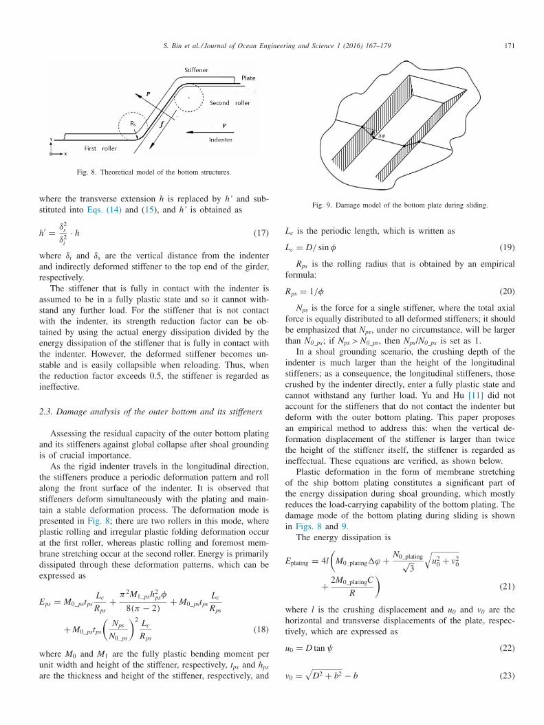
ard corner elements and transversely stiffened plate elementssee Fig. 11 ).
The longitudinally stiffened plate element consists of a lon-itudinal stiffener with an attached plate, and the breadth of
S. Bin et al. / Journal of Ocean Engineering and Science 1 (2016) 167–179 173
Fig. 11. Example of element subdivision.
Table 1 Failure modes according to IACS CSRs.
Element type Failure mode
Hard corner or element subject to tension
Elastic perfectly plastic failure
Longitudinally stiffened plate a. Beam column buckling element subject to compression b. Torsional buckling
c. Web local buckling of flat bar d. Web local buckling of flanged
profile Transversely stiffened plate element Plate buckling
t
j
i
a
s
s
a
(
o
o
r
l
3
t
u
a
s
p⎧⎪⎪⎪⎨⎪⎪⎪⎩
w
z
l
o
w⎧⎪⎪⎪⎨⎪⎪⎪⎩χ
w
m
t
i
c
ε
w
t
p
r
h
d
t
a
d
h
t
p
t
t
n
w
e
s
t
c
b
s
w
M
w
n
r
d
he attached plate is equal to the average spacing of the ad-acent stiffeners. The hard corner elements, which normallynclude the plating area adjacent to the intersecting platesnd the rounded plate, have a large stiffness. The transverselytiffened plate element includes a flat plate with a transversaltiffener or only a piece of the plate.
The stress–strain relationships of the elements in this paperre obtained according to the new common structural rulesCSRs) [22] . The failure modes for the ultimate limit statef the elements subject to predominantly axial compressiver tensile loads are categorized in Table 1 . The stress–strainelationship of the element when the failure mode is mostikely to occur will be chosen.
.3. Calculation process of the proposed method
Once the load-shortening curve of each element is ob-ained, the contribution of each element to the hull girderltimate strength can be calculated by an incremental-iterativepproach. In the first step, it is necessary to estimate the po-ition of the initial neutral axis, which is presented through aoint with coordinates:
N A y1 =
∑
A i y i ∑
A i
N A z1 =
∑
A i z i ∑ A i
(28)
here A i is the sectional area of element i and y i and i are the distances of the centroid of element i to the centreine and base line, respectively.
It is assumed that the increment of curvature that is appliedn the hull girder is fixed and equal to the initial curvature,hich is expressed as
χy1 =
0. 01
σy
E
Y d − N y1
χz1 =
0. 01
σy
E
Z d − N z1
(29)
1 = �χ =
√
χy1 2 + χz1
2 (30)
here σy is the yield stress of the material, E is Young’sodulus of the material, Y d is the distance from the broadside
o the centre line, Z d is the distance from the upper deckn a sagging condition or outer bottom plating in a hoggingondition to the base line.
Then, the strain in each element can be obtained as
i = χ j (z gi cos θ − y gi sin θ
)(31)
here χ j is the curvature of step j , y gi and z gi are the horizon-al and vertical distances of the centroid of element i to theoint of intersection of the neutral axis and the centre line,espectively, and θ is the angle between the neutral axis andorizontal line. Once the state of strain in each element isetermined, the corresponding stresses can be obtained fromhe load-shortening curves.
To achieve equilibrium, the summations of the forces abovend below the neutral axis should be equal, which is alwaysifficult to determine because the effective neutral axis mayave moved due to the non-linear response to the incremen-al curvature. Hence, it is necessary to adjust the neutral axisosition, recalculate the element strains, stresses and total sec-ional force and iterate until the total forces above and belowhe neutral axis are equal. The criterion for judging when theeutral axis position meets the requirement is written as ∣∣∣∣∑
A it σit −∑
A ic σic ∑
A it σit
∣∣∣∣ ≤ 0. 001 (32)
here A it and A ic are the areas of stretched and compressedlement i , respectively, and σit and σic are the stresses oftretched and compressed element i , respectively. The shift ofhe neutral axis �NA should be less than 0.001 mm.
Once equilibrium is achieved, the stress of each elementan be calculated based on the new neutral axis. Then, theending moment due to the imposed curvature is obtained byumming the moment contribution of each structural element,hich can be expressed as
j =
∑
A i σi l i (33)
here l i is the distance from the centroid of element i to theeutral axis.
The iteration ends when the slope of the moment–curvatureelationship curve is smaller than a certain level
M/d χ < c (34)
174 S. Bin et al. / Journal of Ocean Engineering and Science 1 (2016) 167–179
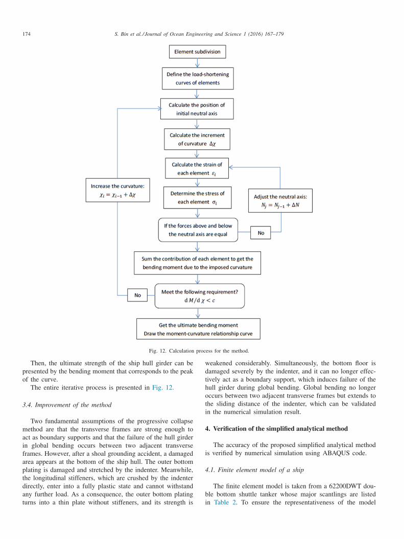
Fig. 12. Calculation process for the method.
w
d
t
h
o
t
i
4
i
4
b
i
Then, the ultimate strength of the ship hull girder can bepresented by the bending moment that corresponds to the peakof the curve.
The entire iterative process is presented in Fig. 12.
3.4. Improvement of the method
Two fundamental assumptions of the progressive collapsemethod are that the transverse frames are strong enough toact as boundary supports and that the failure of the hull girderin global bending occurs between two adjacent transverseframes. However, after a shoal grounding accident, a damagedarea appears at the bottom of the ship hull. The outer bottomplating is damaged and stretched by the indenter. Meanwhile,the longitudinal stiffeners, which are crushed by the indenterdirectly, enter into a fully plastic state and cannot withstandany further load. As a consequence, the outer bottom platingturns into a thin plate without stiffeners, and its strength is
eakened considerably. Simultaneously, the bottom floor isamaged severely by the indenter, and it can no longer effec-ively act as a boundary support, which induces failure of theull girder during global bending. Global bending no longerccurs between two adjacent transverse frames but extends tohe sliding distance of the indenter, which can be validatedn the numerical simulation result.
. Verification of the simplified analytical method
The accuracy of the proposed simplified analytical methods verified by numerical simulation using ABAQUS code.
.1. Finite element model of a ship
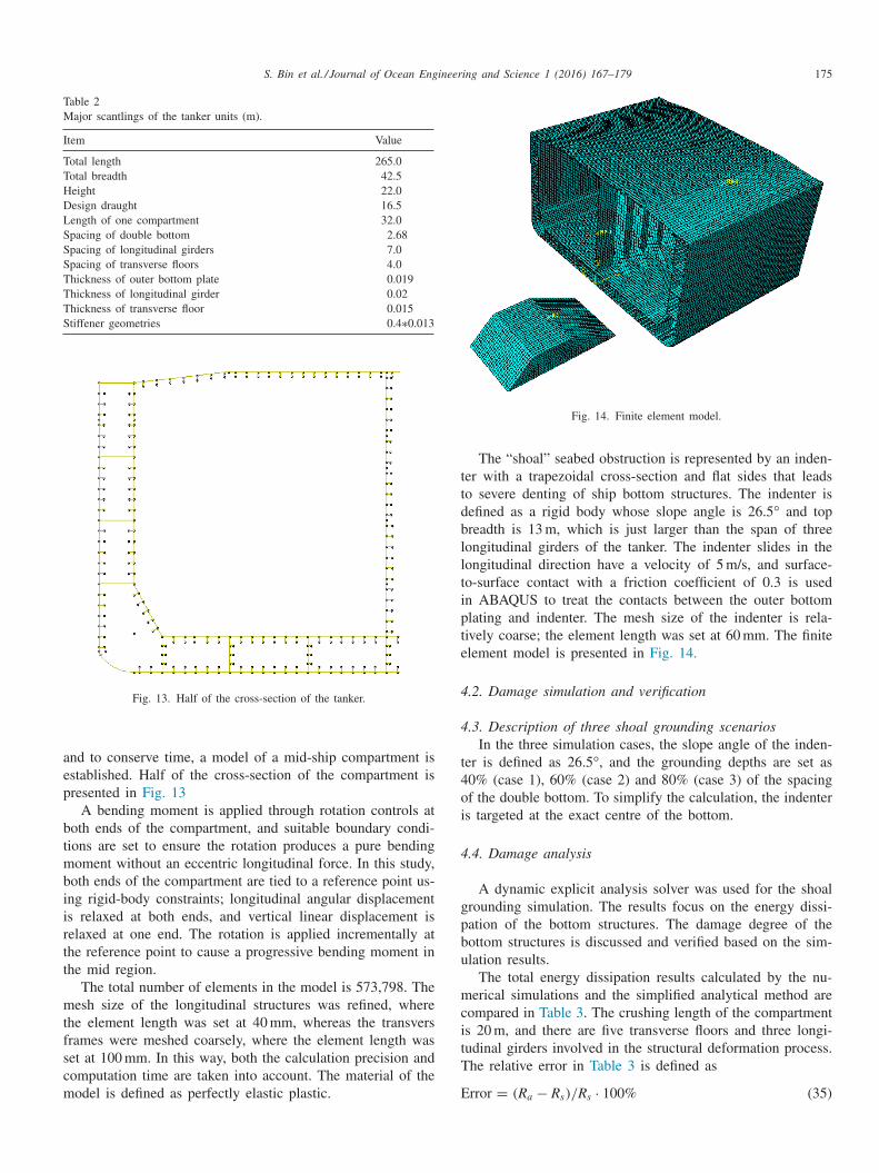
The finite element model is taken from a 62200DWT dou-le bottom shuttle tanker whose major scantlings are listedn Table 2 . To ensure the representativeness of the model
S. Bin et al. / Journal of Ocean Engineering and Science 1 (2016) 167–179 175
Table 2 Major scantlings of the tanker units (m).
Item Value
Total length 265 .0 Total breadth 42 .5 Height 22 .0 Design draught 16 .5 Length of one compartment 32 .0 Spacing of double bottom 2 .68 Spacing of longitudinal girders 7 .0 Spacing of transverse floors 4 .0 Thickness of outer bottom plate 0 .019 Thickness of longitudinal girder 0 .02 Thickness of transverse floor 0 .015 Stiffener geometries 0 .4 ∗0.013
Fig. 13. Half of the cross-section of the tanker.
a
e
p
b
t
m
b
ii
r
t
t
m
t
f
s
c
m
Fig. 14. Finite element model.
t
t
d
b
l
l
t
i
p
t
e
4
4
t
4
o
i
4
g
p
b
u
m
c
i
t
T
E
nd to conserve time, a model of a mid-ship compartment isstablished. Half of the cross-section of the compartment isresented in Fig. 13
A bending moment is applied through rotation controls atoth ends of the compartment, and suitable boundary condi-ions are set to ensure the rotation produces a pure bendingoment without an eccentric longitudinal force. In this study,
oth ends of the compartment are tied to a reference point us-ng rigid-body constraints; longitudinal angular displacement s relaxed at both ends, and vertical linear displacement iselaxed at one end. The rotation is applied incrementally athe reference point to cause a progressive bending moment inhe mid region.
The total number of elements in the model is 573,798. Theesh size of the longitudinal structures was refined, where
he element length was set at 40 mm, whereas the transversrames were meshed coarsely, where the element length waset at 100 mm. In this way, both the calculation precision andomputation time are taken into account. The material of theodel is defined as perfectly elastic plastic.
The “shoal” seabed obstruction is represented by an inden-er with a trapezoidal cross-section and flat sides that leadso severe denting of ship bottom structures. The indenter isefined as a rigid body whose slope angle is 26.5 ° and topreadth is 13 m, which is just larger than the span of threeongitudinal girders of the tanker. The indenter slides in theongitudinal direction have a velocity of 5 m/s, and surface-o-surface contact with a friction coefficient of 0.3 is usedn ABAQUS to treat the contacts between the outer bottomlating and indenter. The mesh size of the indenter is rela-ively coarse; the element length was set at 60 mm. The finitelement model is presented in Fig. 14.
.2. Damage simulation and verification
.3. Description of three shoal grounding scenarios In the three simulation cases, the slope angle of the inden-
er is defined as 26.5 °, and the grounding depths are set as0% (case 1), 60% (case 2) and 80% (case 3) of the spacingf the double bottom. To simplify the calculation, the indenters targeted at the exact centre of the bottom.
.4. Damage analysis
A dynamic explicit analysis solver was used for the shoalrounding simulation. The results focus on the energy dissi-ation of the bottom structures. The damage degree of theottom structures is discussed and verified based on the sim-lation results.
The total energy dissipation results calculated by the nu-erical simulations and the simplified analytical method are
ompared in Table 3 . The crushing length of the compartments 20 m, and there are five transverse floors and three longi-udinal girders involved in the structural deformation process.he relative error in Table 3 is defined as
rror = ( R a − R s ) / R s · 100% (35)

176 S. Bin et al. / Journal of Ocean Engineering and Science 1 (2016) 167–179
Table 3 Energy dissipation results and comparison units (J).
Case Simulation results Analytical results Relative error
1 4 .80E + 08 4 .44E + 08 –7 .5%
2 6 .31E + 08 6 .13E + 08 –2 .9%
3 7 .38E + 08 8 .0E + 08 8 .4%
g
a
t
p
e
F
i
p
o
i
i
t
t
t
s
t
t
f
i
t
p
1
Fairly good agreement between the two methods was ob-tained. Therefore, the combination of the individual analyt-ical methods is accurate. Assuming the initial velocity ofthe tanker is 5 m/s, the obtained sliding distances are 7.75 m,5.30 m and 3.84 m for the three cases according to the law ofconservation of energy.
The damage degree of the bottom structure can be deter-mined by an analytical method. In case 1, the outer bottomplating is deformed, the longitudinal stiffeners that contact theindenter directly are in a fully plastic state and cannot with-stand any further load together with two stiffeners in eachflank. The uppermost stiffeners of the three longitudinal gird-ers are still effective, along with their attached plate. In case 2,four stiffeners of the outer bottom plate in each flank lose ca-pacity together with all the stiffeners of the three longitudinal
Fig. 15. Damage deformation mode of the stiffened out
Fig. 16. Damage deformation mode of the stiffened out
irders; however, 20% of the top of three longitudinal girdersre still effective. In case 3, all damaged stiffeners and longi-udinal girders lose efficacy; only the deformed outer bottomlating is still effective. The simulation stress plots of the stiff-ned outer bottom plates and longitudinal girders are shown inigs. 15 –17.
For the stiffeners in each flank that do not contact thendenter directly, an empirical method was proposed in therevious section: when the vertical deformation displacementf the stiffener is larger than twice the height of the stiffenertself, the stiffener is regarded as ineffective. The stiffenersn each flank that deformed with the outer bottom plating inhe three accident scenarios are presented in Fig. 18 usinghe empirical method. The red line represents the position ofwice the height of the stiffener. The black thick lines repre-ent the position of the outer bottom plating that correspondso the damage scenarios. The blue fine lines represent the ver-ical positions of the stiffeners. As seen from the plots, two,our and five stiffeners lose their capacities when the ground-ng depths are set as 40%, 60% and 80% of the spacing ofhe double bottom, respectively. The agreement of the em-irical results with the simulation results presented in Figs.5–17 verifies the validity of the empirical method.
er bottom plate and longitudinal girders in case 1.
er bottom plate and longitudinal girders in case 2.

S. Bin et al. / Journal of Ocean Engineering and Science 1 (2016) 167–179 177
Fig. 17. Damage deformation mode of the stiffened outer bottom plate and longitudinal girders in case 3.
Fig. 18. Deformation of the stiffeners in the flank.
Fig. 19. Moment–curvature relationship of case 1.
4
e
a
Fig. 20. Moment–curvature relationship of case 2.
Fig. 21. Moment–curvature relationship of case 3.
t
o
i
a
.5. Progressive collapse analysis
To complete the damage analysis, the damaged ship mod-ls are further subjected to incremental bending moments tossess their progressive collapse and ultimate strength charac-
eristics. The results are compared with the ultimate strengthf an intact compartment, and the analytical method proposedn this paper is verified; comparisons with the conventionalnalytical method are also presented in this section.
178 S. Bin et al. / Journal of Ocean Engineering and Science 1 (2016) 167–179
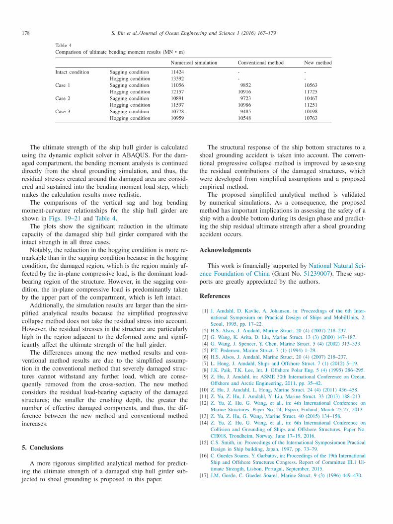
Table 4 Comparison of ultimate bending moment results (MN • m)
Numerical simulation Conventional method New method
Intact condition Sagging condition 11424 - - Hogging condition 13392 - -
Case 1 Sagging condition 11056 9852 10563 Hogging condition 12157 10916 11725
Case 2 Sagging condition 10891 9723 10467 Hogging condition 11597 10986 11251
Case 3 Sagging condition 10778 9485 10198 Hogging condition 10959 10548 10763
s
t
t
w
e
b
m
s
i
a
A
e
p
R
[[[
[[
[
[
[
The ultimate strength of the ship hull girder is calculatedusing the dynamic explicit solver in ABAQUS. For the dam-aged compartment, the bending moment analysis is continueddirectly from the shoal grounding simulation, and thus, theresidual stresses created around the damaged area are consid-ered and sustained into the bending moment load step, whichmakes the calculation results more realistic.
The comparisons of the vertical sag and hog bendingmoment-curvature relationships for the ship hull girder areshown in Figs. 19–21 and Table 4 .
The plots show the significant reduction in the ultimatecapacity of the damaged ship hull girder compared with theintact strength in all three cases.
Notably, the reduction in the hogging condition is more re-markable than in the sagging condition because in the hoggingcondition, the damaged region, which is the region mainly af-fected by the in-plane compressive load, is the dominant load-bearing region of the structure. However, in the sagging con-dition, the in-plane compressive load is predominantly takenby the upper part of the compartment, which is left intact.
Additionally, the simulation results are larger than the sim-plified analytical results because the simplified progressivecollapse method does not take the residual stress into account.However, the residual stresses in the structure are particularlyhigh in the region adjacent to the deformed zone and signif-icantly affect the ultimate strength of the hull girder.
The differences among the new method results and con-ventional method results are due to the simplified assump-tion in the conventional method that severely damaged struc-tures cannot withstand any further load, which are conse-quently removed from the cross-section. The new methodconsiders the residual load-bearing capacity of the damagedstructures; the smaller the crushing depth, the greater thenumber of effective damaged components, and thus, the dif-ference between the new method and conventional methodincreases.
5. Conclusions
A more rigorous simplified analytical method for predict-ing the ultimate strength of a damaged ship hull girder sub-jected to shoal grounding is proposed in this paper.
The structural response of the ship bottom structures to ahoal grounding accident is taken into account. The conven-ional progressive collapse method is improved by assessinghe residual contributions of the damaged structures, whichere developed from simplified assumptions and a proposed
mpirical method. The proposed simplified analytical method is validated
y numerical simulations. As a consequence, the proposedethod has important implications in assessing the safety of a
hip with a double bottom during its design phase and predict-ng the ship residual ultimate strength after a shoal groundingccident occurs.
cknowledgments
This work is financially supported by National Natural Sci-nce Foundation of China (Grant No. 51239007 ). These sup-orts are greatly appreciated by the authors.
eferences
[1] J. Amdahl , D. Kavlie , A. Johansen , in: Proceedings of the 6th Inter-national Symposium on Practical Design of Ships and MobilUnits, 2,Seoul, 1995, pp. 17–22 .
[2] H.S. Alsos , J. Amdahl , Marine Struct. 20 (4) (2007) 218–237 . [3] G. Wang , K. Arita , D. Liu , Marine Struct. 13 (3) (2000) 147–187 . [4] G. Wang , J. Spencer , Y. Chen , Marine Struct. 5 (4) (2002) 313–333 . [5] P.T. Pedersen , Marine Struct. 7 (1) (1994) 1–29 . [6] H.S. Alsos , J. Amdahl , Marine Struct. 20 (4) (2007) 218–237 . [7] L. Hong , J. Amdahl , Ships and Offshore Struct. 7 (1) (2012) 5–19 . [8] J.K. Paik , T.K. Lee , Int. J. Offshore Polar Eng. 5 (4) (1995) 286–295 . [9] Z. Hu , J. Amdahl , in: ASME 30th International Conference on Ocean,
Offshore and Arctic Engineering, 2011, pp. 35–42 . 10] Z. Hu , J. Amdahl , L. Hong , Marine Struct. 24 (4) (2011) 436–458 . 11] Z. Yu , Z. Hu , J. Amdahl , Y. Liu , Marine Struct. 33 (2013) 188–213 . 12] Z. Yu , Z. Hu , G. Wang , et al. , in: 4th International Conference on
Marine Structures. Paper No. 24, Espoo, Finland, March 25-27, 2013 . 13] Z. Yu , Z. Hu , G. Wang , Marine Struct. 40 (2015) 134–158 . 14] Z. Yu , Z. Hu , G. Wang , et al. , in: 6th International Conference on
Collision and Grounding of Ships and Offshore Structures. Paper No.CH018, Trondheim, Norway, June 17–19, 2016 .
15] C.S. Smith , in: Proceedings of the International Symposiumon PracticalDesign in Ship building, Japan, 1997, pp. 73–79 .
16] C. Guedes Soares , Y. Garbatov , in: Proceedings of the 19th InternationalShip and Offshore Structures Congress. Report of Committee III.1 Ul-timate Strength, Lisbon, Portugal, September, 2015 .
17] J.M. Gordo , C. Guedes Soares , Marine Struct. 9 (3) (1996) 449–470 .

S. Bin et al. / Journal of Ocean Engineering and Science 1 (2016) 167–179 179
[
[
[
[
[
18] R.M. Luis , A.W. Hussein , C. Guedes Soares , in: 10th Symposium onPractical Design of Ships, Houston, 2007 .
19] J.K. Paik , A.K. Thayamballi , S.H. Yang , Marine Technol. 35 (1) (1998)38–54 .
20] J.M. Gordo , C. Guedes Soares , in: Proceedings of the 9th InternationalCongress Of International Maritime Association Of The Mediterranean,Ischia, 2000, pp. 79–86 .
21] A.W. Hussein , C. Guedes Soares , Ocean Eng. 36 (17) (2009)1446–1459 .
22] IACS , in: International Association of Classification Societies, London,2006 .