s ''. . . i 4 nuclear generating plant ., n
TRANSCRIPT

. _ _ _ . . -.._ .- -.-... ... .-_ ._..-.. .-...-.-_.- . .. ... - . _ . - . _ . _ . . _ . . . - . - . _ . - . . . . .
f
j, GRAIRIE ISLAND NUCLEAR GENERATING PLANT';
NORTHERN STATES POWER COMPANY H PROCEDURES
j 9[ } ] 1:6% " , . TITLE: NUMBERt''i' [,;g INTEGRAL WELDED ATTACHMENT H7.3
*
I5 EVALUATION CRITERIAi
b- m: 0'
isection - FOR THE PRAIRIE ISLANDs''. . .
i' ~
NUCLEAR GENERATING PLANT Page 1 of 214
!
.,
n
a
!1
b
i.
If
:',
!,
3
!
I.
1
:
I
!'4
|
||
l
i
i
i
! ' ^
rO.C. REVIEW DATE: REVIEWED By: j DATE:tw J i_2
(l // /!;' . i. 3APPROVED BY: DATE: 1 , ., ,
' / , j/- \ ..
,
9212220341 921211PDR ADOCK 05000282PDRP
. , _ . . _ - _ . . _._ _ _ ..... _ _____.._ . _.._ _ .._ .._. .. .._.. _ ,._.._.__.- ~.~. _ .

. _ - . ._ - . . _ . . . _ _ _ _ - _ . _ . _ , .-. . - _ _ .
.
c H7.3Rev. O
Table of Contents Page 2
.
f12A
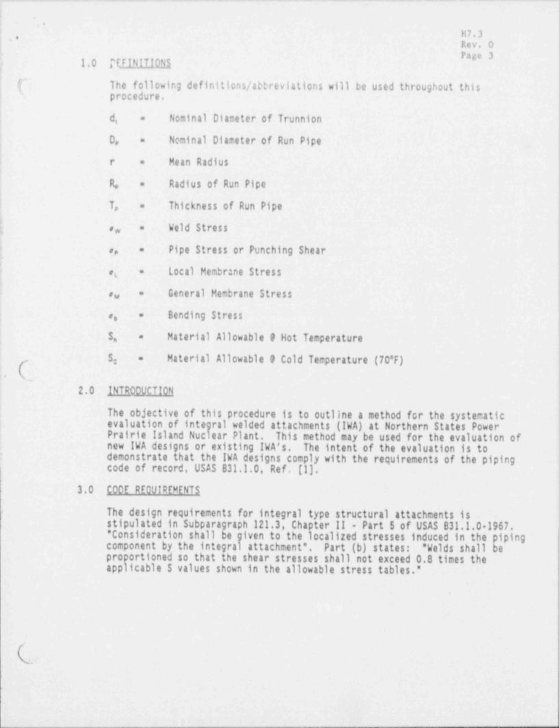
1.0 DEFINITIONS 1
2.0 INTRODUCTION 1
3.0 CODE REQUIREMENTS 1
4.0 ANALYSIS AND DESIGN CRITERIA 2
4.1 Weld Criteria 24.2 Pipe Stress Screening Criteria 24.3 Detailed Local Stress Criteria 3
5.0 EVALUATION HETH000 LOGY 6
6.0 REFERENCES 7
No. of Paaes
( APPENDIX A: IWA Evaluation Flow Chart 2
APPENDIX B: Configuration 1-9 10
;
- _ . . _.. _ .
_ _ _ _ - - _ ___ ____.._. _ _ _ _ - - - -
!: .
..1 -
11 7 . 3 -i '' Rev. O! Page 3i 1.0 TEFINITIONS!| /f The following definitions / abbreviations will be used throughout this| procedure.x!
| d, Nominal Diameter of Trunnion=
D, Nominal Diameter of Run Pipe=
i r - Mean Radius.
! Ij_ R, Radius of Run Pipe=
i
! T, Thickness of Run Pipe-
1
[ Weld Stress=,,
f: Pipe Stress or Punching Shear,, -
,, Local Membr:ne Stress=
'General Membrane Stress-au
j!l
,, Bending Stress-
|
| S, Material Allowable 9 Hot Temperature-
) S: Material Allowable 9 Cold Temperature (70"F)-
:. C.1 2.0 INTR 00VCTION
The objective of this procedure is-to outline a method for the systematici evaluation of integral welded attachments (IWA) at Northern States Power! Prairie Island Nuclear Plant. This method may be used for the evaluation of; new IWA designs or existing IWA's. The intent of the evaluation is to
demonstrate that the IWA designs comply with the requirements of the piping:'
-
codeofrecord,USASB31.1.0,Ref.(1).-
3.0 CODE RE0VIREMENTS-r
The design requirements for integral type structural- attachments isF
stipulated in Subparagraph 121.3, Chapter II - Part 5 of USAS B31.1.01967. -" Consideration shall be given to the localized stresses induced in the )iping_component by the integral attachment". Part-(b) states: " Welds shall Je-
--
proportioned so that the shear stresses shall not exceed 0.8 times:the-applicable S values shown-in the allowable stress tables."
.
9
,
- -
*.
'
.
H7.3 '
. Rev. OPage 4
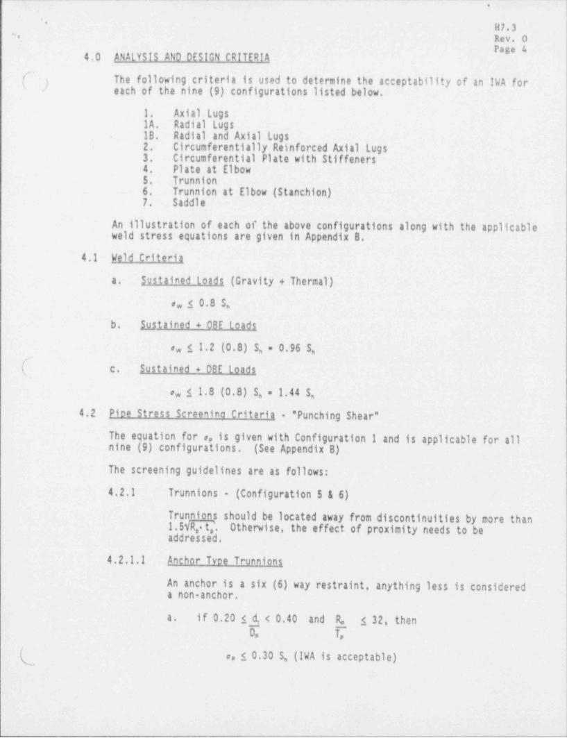
4.0 ANALYSIS AND DESIGN CRITERIA
(^ ) The following criteria is used to determine the acceptability of an IWA foreach of the nine (9) configurations listed below.'
-
1. Axial LugsIA. Radial LugsIB. Radial and Axial Lugs2. Circumferential1y Reinforced Axial Lugs3. Circumferential Plate with Stiffeners4. Plate at Elbow5. Trunnion6. Trunnion at Elbow (Stanchion)7. Saddle
An illustration of each of the above configurations along with the applicableweld stress equations are given in Appendix B.
4.1 Held Criteria
a. Sustained loads (Gravity + Thermal)
w I 0.8 S,a
b. Intained + OBE loads1
,, s 1.2 (0.8) 5, = 0.96 S,
( c. Sustained + DBE loads
w 1 1.8 (0.8) S,= 1.44 S,a
4.2 Pioe Stress Screenina criteria " Punching Shear"
The equation for a, is given with Configuration 1 and is applicable for allnine (9) configurations. (SeeAppendixB)
The screening guidelines are as follows:
4.2.1 Trunnions - (Configuration 5 & 6)
Trunnions should be located away from discontinuities by more than.
1. 5 VR t '. Otherwise, the effect of proximity needs to beaddre,s s e,d . t
4.2.1.1 Anchor Tvoe Trunnions
An anchor is a six (6) way restraint, anything less is considereda non-anchor.
a. if 0.201 d, < 0.40 and R. 1 32, thenD, T,
ap 10.30 S, (IWA is acceptable),

. . _ .
.
11 7 . 3..
, , , Rev. Ol' age 5
b. if 0.40 5 d, < 0.60 and R, s 16, thenD, T,
,, s 0.40 S, (IWA is acceptable)
.
c. if 0.60 1 d and A s 12, thentD, T,
e, s 0.60 S, (IWA is acceptable)
d. if 0.60 s d and 12 < R. 5 24, thenaD, T,
,
,, s 0.40 S, (IWA is acceptable)-| 4.2.1.2 Non-Anchor Tvoe Trunnions
'
for 0.20 s i,
D,
,, s 0.15 S (IWA is acceptable).
4.2.2 Lugi - (Configurations 1, 2, 3, 4, 7)
When more than one (1) lug is used, the separation distancef.. will be compared to 1.5 R, t,
4.2.2.1 Axial-Luas
* ,,10.40 S (IWA is acceptable)'
4.2.2.2 Radial lu,gi.
* ,, s' 0.15 S, (1WA~ is acceptable)-
4.3 Detailed local Stress criteria
Supports with.IWA's not meeting the criteria set forth in Section 4.2will be evaluated on an individual basis using methods applicable to -pressure vessels ~or pi)ing. For lugs the WRC 107 methodology asoutlined-in 4.3.1 may_se used. Two different methods are used fortrunnions:
- WRC 107 for r _ s 0.5. .
r, *
-
-
-
*

_ . - _ . _ . ... _ __. _. . -
-
H7.3,
. Rev. 0,
Page 6- Rodabaugh for r_10.5
r,
4.3.1 WRC 107 METHODOLOGY
~; The Welding Research Council Bulletin 107 outlines a methodof calculating local stress on a thin walled ves'sel. PerASME B&PV Code, Section III, Table NC-3321-2, Ref (6]. The
'
WRC of 107 stresses can be categorized into the following:
et - Local MembraneQ Secondary BendingF - Peak
3 The acceptance criteria below is taken from ASME B&PV CodeClass 2 vessel rules which only consider ,t, ,, and ,, (seedefinitions). To calculate the local membrane stresses using,
the WRC 107 methodology, set the stress concentration factorfor bending, K equal t (au + ,,) is being used hereto designate tb,e gross )o zero.ipe stresses which include the"
i pressure stresses and tle stresses induced by the moments inthe pipe as predicted by the piping analysis. The limitsare as follows:
,
d
a. Level A (Gravity + Thermal)
,e + (,u + ,,) i 1. 5 So
( b level B (Gravity + Thermal + OBE)
,e + (,u + ,,) i 1.8 S,
Level D (Gravity + Thermal + DBE)c.,
,e + ( au + ,,) s 2.4 S,
If the trunnion in question is an anchor, then the WRC 107,
are the total stresses (except for pressure). Gross pipe3'
stresses are accounted for in WRC 107 in this case and theM/Z pipe stresses from the piping analysis need not be4
added.
4.3.2 Rodabauch Methodoloav
The method of WRC 107 cannot be used for geometries withTrunnion to pipe radii greater than 0.5 without severeextrapolation. A different method, based on recent work byDr. E.C. Rodabaugh on laterals will be used. In general,the geometries in this category are the larger trunnions,typically anchors, dominated by moments. Since the trunnionto the pipe is similar to a lateral, without the weakeningof the hole, the Rodabaugh approach will be used. Proper useof this paper requires some background from WRC
( l;
- . - -_ _ -- .

_ _._______ . _ . _ _ . _ _ . .___ _ . . - _ _ _ . _ . . _ _ . __ _ _.
' *
H7.3j.. Rev. Oj Page 7j Bulletin 329, Ref. [8]. This second approach is therefore
limited to anchors or restraints with primarily moment. f loadings. The loading will be treated as "Homent Loading on#
'- the Branch" as explained in E.C. Rodabaugh's paper. The
following indices are required:
C - 1.5 ( B ) * ( I )'# ( 1 )( I ) ; > 1.5 for I < 0.93; T R T r, R,
: =0.9-(R)'d (I);I=1[ T r, R;
j B - 0.5 C i > 1.03 3i
; i -C ; > 2.13.
| These are for "As-Welded" intersections. For anchors, thej stress is theni
|!Bn _fL where Zb = ,r't per NB-3683.1
Zb:! or
Y i M
: Zbi
j Depending en the loads t,eing considered...
| In calculating stres'ses due to loads', conservatively use the4
smaller of Branch /Run section. Since the loads on-theanchor are the sum of the two sides, they are of like sign
; for seismic and usually of like sign for thermal, although| this should be verified. :This means only.the loads on thei
Branch need to be used in the " Tee" evaluation.-
For seismic, the run moments are always assumed to add'| - absolutely. There is no need to add run moment-stresses.to
the " tee", since ASME code states that M loads are usuallyi - 0 if the two run; moments are of-like sign. Since gravity
.
! small, they will be assumed to have same sign. -If thermal'
run moments are cancelling, the evaluation needs to be-! modified to account for this. .The-acceptance limits are-as
'
; follows:i
| a. Sustained loads (Gravity + Pressure)
i B, PDo + B M i 1. 5 ' S. -
3
! 2 t, 1, B, 0|5
|- b. Sustained + OBE' Loads
Po,.0, + B M s 1.8 S,3t 4 t, Zb
.
!
_ _
--
su u- -v9re7-w -v- -----e,e -g,cet-=-- 9-y-v-g -i=%--^-- ty-v-.,-ga.,--%.y a-,mw- t ,.w- ,y,:.-. .ir. gew-a---7g -n 9 rw-s q'w-w''w-*--- me en e g 9-** r

.- _ ,_- -- _. -= _- - . _- . _- -
'
11 7 . 3; .
;,- Rev. OPage 8
c. Sustained + OBE toads
(' Po.,0, + B M s 3.0 S,,, 3
4 t, Zb
d. Thermal (Fatiaue) Loads,
i M _ s S, = 1. 25 S, + . 2 5 S,,,
j Zb,
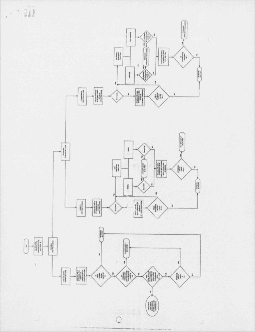
5.0 EVALVATION METHODOLOGY1
The evaluation methodology for a new or existing IWA's is outlined in theflowchart in Appendix A. From the flowchart it is seen that the nine (9) |
configurations of IWA's fall into two (2) categories: Lugs and Trunnions. '
q.
a. Classify the IWA into one of the nine (9) configurations. This will |. also determine whether the IWA is a Lug or Trunnion. If the IWA cannot |'
be classified as one of the nine (9) configurations, then it will beconsidered non standard. These configurations will need to be4
2
evaluated on a case by case basis using appropriate experience andstructural mechanics concepts.
:j b. Based on the configuration, calculate, using maximum loads, the " weld"
stress" (,,) and the " pipe stress" (a,) for the attachment. Fortrunnions, also calculate the
!
(..geometric parameters d, and R.
D, T,
Compare weld stress against " Sustained Load" weld criteria (,, 1 0.8c.S ). If weld stress exceeds " Sustained Load" limits, then compare weldstresses for the individual load cases with the appropriate weldcriteria limits as shown in 4.1 and outlined in the flow chart.
d. Determine acceptability of IWA by comparing pipe stress to the limitsspecified in Section 4.2. For trunnions, the geometric parameters willdetermine the pipe stress limits.
If the pipe stress exceeds the limits specified in Section 4.0, locale.stress evaluation can be performed using either WRC Bulletin 107 or theE.C. Rodabaugh approach. The maximum stresses calculated by either ofthese two (2) methods must be compared to their respective limits basedon loads used. See Section 4.3 for the local stress limits for theindividual loading conditions. If the local stresses do not exceedthese limits, the IWA is qualified and considered acceptable. If theIWA exceeds these limits, then the existing IWA must be modified, orthe new design must be changed and the evaluation process re-iterated.
k'
. . - . . . . .

- -. . - - _ _ . _ - _ . . - . .__- -_. . - . .
,- H7.3*- Rev. 0
6.0 REFERENCES Page 9
{ 1. USAS B31.1.0, " Power Piping", 1967.'
2. Impell Calculation 0910-242-001, " Prairie Island IWACriteria / Evaluation", Revision 0. PINGP Design Change Modification894915, Feb. 9, 1990.
'. Welding Research Council, Bulletin 107, August 196534
| 4. ASME Code Case N-318 3, September 5, 1985.
'
5. ASME Code Case N-392, November 28, 1983
| 6. ASME B&PV Code, Section III, Division I, Subsection NC, 1989 ED.
7. E.C. Rodabaugh, " Stress Indices Pressure Design and StressIntensificatior Factors for Laterals in Piping, Draft.
8. Welding Research Council, Bulletin 329, December 1987
(,
1
|
_ _ . . . -. . .. . . - .- - - .

-. __ _ _ - - - _ _ _ - ..
Rev 0,
Paga 10*,
'.
1 of 2
APPENDILA
IWA Evaluation Flowchart4
%
9
g.,y4 = N%
i x ;- # , ' ,aa '; y - 4 6
. . .
9
%
,, ,, - - , .. __ _ _ _ _ _ _ - _ _ _ _ . . _ _ _ _ _ . _
--.1a w,- 4 e.,a-4- -- G L -0A+- n 1 a m a m - A
,O**
4 .. m a w
S,
i
J,: -fi- .,
4 ,
* *\\ \
- , -,
|.I.
I . i'
- , _ __ e v
u Ii v ili if||8' '
---+.
,
!
!
,
11,1 a '
!g
ms-.,
'i p . Ei
{{ Ij -|
-
|| ||| .lli4
8*
|-
, ,
! I i 11'
, _ . _i s;
:.
:' n,
11-
=
- -f.
, m'8 I ' *,
iji ll || - .: '~ ~
,.
..
,
; 5*8 I f,
[- h' '
||| .iili.|
.|| i, ' f jj e > lii'
- -
',
'
.~ o( : O >-
- -
. --
.
. .. .. .

_ _ _ _ _ _ _ _ _ _ _ _ _ _ _ _ - -
__ _. .
. .
!!7. 3,
. . Rey, oPage 12
APPENDIX B
Configurations 1 9
.
.
t
.
*
. - . . - - . . - . - -- - . - - . - - . . . - . -. _.. .-
,.
''
H7.3..
]'* - Rev. 0' ' Fage 13,
#Cy
1 ( ei
i
ADa.
1
1 i t.
tp; w
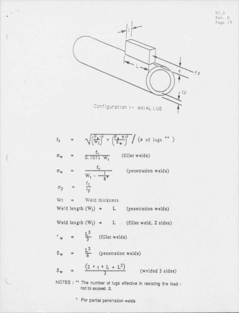
Configuration l- AXI AL l.UG E4
e
4 % + ; ; ; / < a lngs >fr =
~ f'
e, 0.7071 W=
t
f' (penetration welds)o,3
=
W-'
g. ,
| Up "
Weld thicknessWt =
--Weld length (W ) = L- (penet:ation welds)
| .
Weld length (W ) = L- (fillet weld,2 sides)'
2L?, y- (fillet welds)=
.
L2.
S, g- (penetradon welds)=.
(2*t1 L+L)2S, (welded 3 sides)=3
'- NOTES : ** The number of lugs effect!ve In resisting the load -
not to.ex,ceed 2.
|
* For partial pene*1ation welds |

--___ - -- _ -..
'
.
*..
,
4 H7.3
F Rev. OPage 14
0.
' < L+
Configuration -l'a - RADI AL LUG
.
Weld length (Wg) = 2L (fillet weld)
( Weld length (W ) = L (penetration weld)i. . . . .
rF3fr = ; gJ.
\.
.
0.70[f Wet wcWe, =1Wt.
f' g (penetration weld)o, =
W: y ,
-*
For partial penetration welds.
e
.
. _ _ _ _ _ _ _ _

__ _ _ _ _ . _ .. .
,
,5 H7.3*.. Rev. O
Page 15
[; ,
Fr
=g.
Fae2
/ ff 1
l +L _>
l >
LJ LJ
Configuration ib - RAD: AL & AXI AL LUGS
,
-.
Weld length (Wg) = 2L (fillet welds)(.-M, (F 5 c2 )+ (F,2 eg)=
a
2LS, =3-
.
E
f"* 0.7071 W:
'
<
. =
y
.
~
.. .__ _ _ . _ _ _ _ _ _ _ . . _ _ _ _ _ _ _ _ . _ _ . ._
. _ . . . . __ _ . _ . .
.
* H7.3 :. .
,
Rev. 6*Page 16
e-
l( I Fn
) [ "f T 1r
l 1r- - - -
~~| TI I'
-
__,
y' h* g b|-.-- 1n
,
<le 4 Li
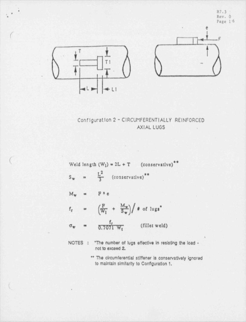
Configuration 2 - CIRCUMFERENTI ALLY REINFORCEDAXI AL LUGS .
.
.
. .
Weld length (Wg) = 2L + T (conservative)* *2L (conservative),,S, = y
Fx eM, =
! # of lug *f " +r
f(fillet weld)c, 0.7071 Wg
=
_
.
NOTES : 'The number of lugs effective in resisting the load -not to exceed 2.
" The circumferential stiffener is conservatively ignoredto maintain similarity to Configuration 1.
|
, .
.
1-- - --_, . . _ _ _ _ _ . , ._ . , _ . _ , . ..|
-- - - - _ , .. .
'
; ..
'. H7.3-"'
Rev. 0;* Page 17
;A,
(' 1 '1
I 1j 4 * p
t I,
44
*.4 ,._ y __ .,_ ;' d. t b - - -6 - - +
(_j,
m ssssusms sus
h= F _
<
+L1+ ->- +T
,
.
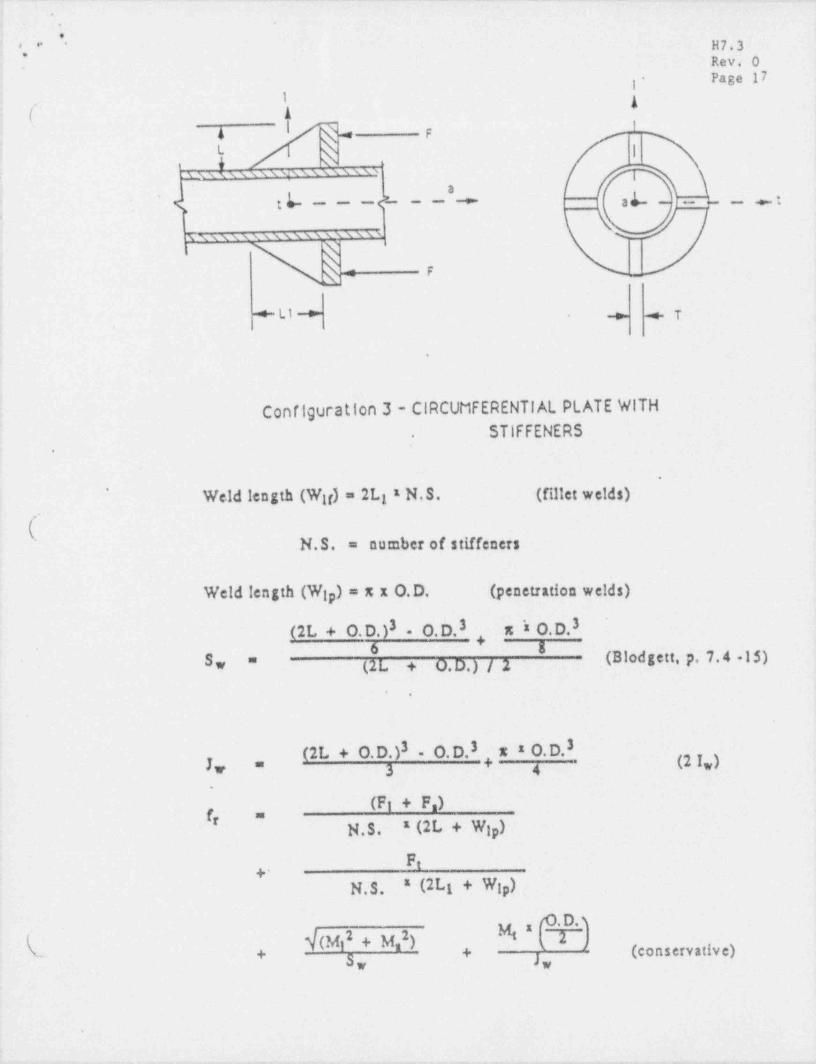
t - Configuration 3 - CIRCUMFERENTIAL PLATE WITHSTIFFENERS,
.
.
Weld length (W d = 2Lg x N.S. (fillet welds)'
i
(" N.S. = number of stiffeners
Weld length (W ) = x x O.D. (penetration welds)ip
(2L + 0. D. )3 - O. D. 3 x 's O.D.3+
6 8 (Blodgett, p. 7.4 -15)S, =- (2 L + 0.D.) / 2
.
x x 0. D.3(2L + 0.D.)3 - O.D.3 + (2I,)J, =3 4
.
(F + F )if' =
N.S. x (2L + W ).ip
F,+-
N.S. (2Lg + W )1 ip
% * C. D. 3( i(Mi + M,2)-. (conservative)
2 <2 ',S, J,
.
.-r - ..e- - r .- m - - - - *r.-m,.,-m<

_ _ _ _ _ _ . . __-
' . " F H7.3'
I Rev. O'
N j. Page 18
|w-- e l+
(-- (O
h I.
eg I-
)I'
U l~~
L
,I
I
I
LSI
-
Configuration 4 - PLATE at ELBOW
(' Weld length (WI) = determined from plate dimensions and radius of
pipe bend...
thickness of plateT =
(F 2 e2) + (F x et)Mg = t
2Wi (assumed to be straight)S, 6
=
3 2Wi + 3W Tiy* ,
6-
fr " -+ +
f' (penetration welds)o, = iW: y ,
f= * * * *' c,
2 x (0.7071) * (W )
* For partial penetration welds
. ..- - _ _ _ _ _ - _ - _ _ _
_-. _ . -. . - _ _ . _ . . .-
. .
'. i H7.3-g '' Rev. 0
*'
'
Page 191
5 gt(. .
| + | d ->
!' 'h|.
' '
| TRUNNION
I -~
.
.
I
I'[ W l
I 1t- - -- --- - - |1
i *a-<
-
, .
J =
| RUN PIPE
i
i
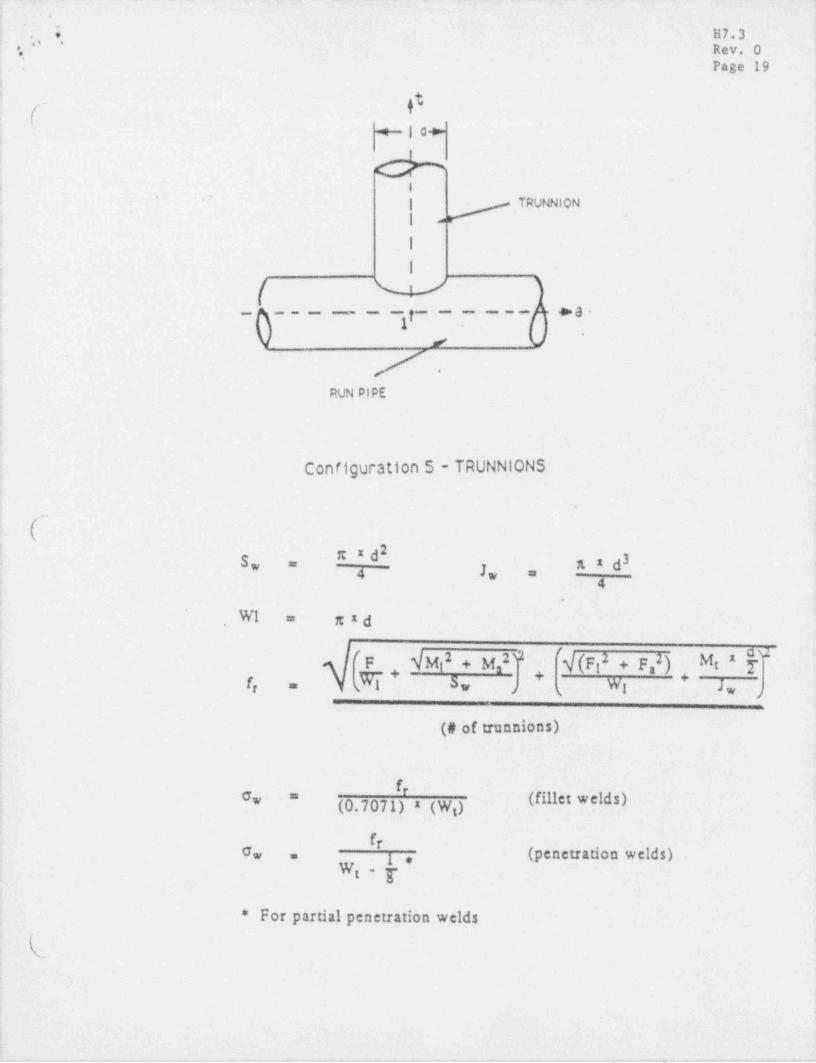
Configuration 5 - TRUNNIONS
{''xxd2 a d3S, =
- J4 w =4,
i -
WI xxd=,
f
y (p,2 + p,2) + Mg xf#
F YM 2+M 2 32i 3.
+f Sw WI lw=r 4 s ( j
'
(# of trunnions)
f
(fillet welds)G =w(0.7071) x (W )
fr3, (penetration welds)Ow .
W: y
For partial penetration welds*
k.
. - _- _ _
- . . . - . . . - . . . .. . ._. . - - - . . . - - . . - . . . - . . _ - - -.
* ,
* "j , H7.3
'#'
|.t Rev. 0
. (tPage 20
.
''
: f'1-
| ! - (L80W2
|.
i- '
i I'
'
TRUNNION
4. [)4- -/
| |'
-
I-
|/
I r. m!
'1
'I
'
.
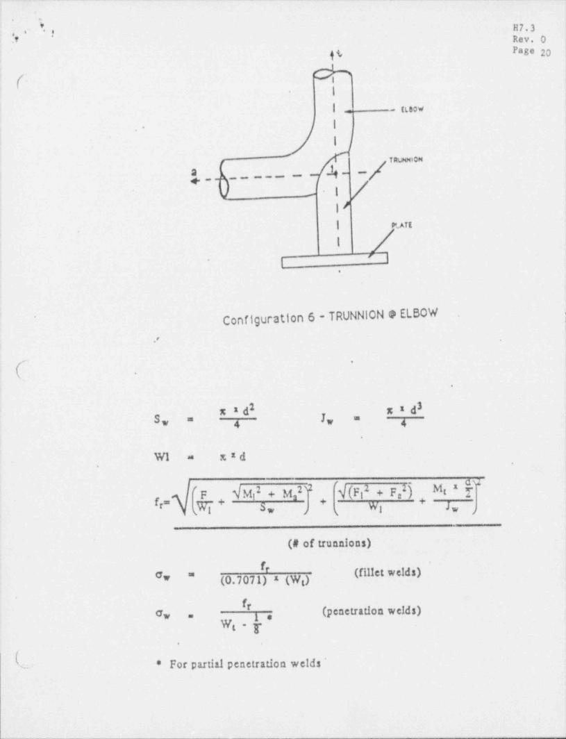
Configuration 6 - TRUNNION e ELBOW ..
* ..,
8 .
'
.
2 3x2d. g,Iw3* 4 ".
,4
= x xdW1, ,
,
'F iM 2 + g,2 32 'q(p 2 + p,2[. Mg 2fi -
fr, y,- _3, Wl Jw+ +
,
(# of trunnions)'
* Wet weMs)#* (0.7071) x (w,)*
# (penetration. welds)"w 1=
Wg y ..
(* For partial penetration welds '*

- . . _ - - - -.
4. ;
*. ' i'
11 7 . 3.
,, Rev. 0' Page 2i
Fr
I os ye
/
0a-
.
|I
NWI
I||s
NN
L s4
i s
*a,.
i
; Configuration 7 - SADDLE LUG
~
.
'
(~ Weld length (W:) = are length.
| 2Tp (penetration weld)S, =
2Tp (fillet weld)S, =
!F, x e| M. =
|
f'' " *.
|
| t' ' (penetration weld)-; e, =3
W: y , ' -
|
|
| f(fillet weld)Gw -=
0.7071 x We!
.For partial penetration welds
(
.
|+ . , . . _ _ . . - . . _- _ , . . - , _ . _ . _ . - - , , , , . ,