s in gu larity-in va rian t l eg sub stitu tion s in p en ... · s in gu larity-in va rian t l eg...
TRANSCRIPT
Singularity-Invariant Leg Substitutions in Pentapods
Júlia Borràs and Federico Thomas
Abstract— A pentapod is usually defined as a 5-degree-of-freedom fully-parallel manipulator with an axial spindle asmoving platform. This kind of manipulators have revealed as aninteresting alternative to serial robots handling axisymmetrictools. Their particular geometry permits that, in one tool axis,inclination angles of up to 90 degrees are possible thus over-coming the orientation limits of the classical Stewart platform.
This paper presents a solution to the problem of finding thosechanges in the location of the leg attachments of a pentapodthat leave its singularity locus invariant. Although the solutionto this problem does not provide a fully characterization of thesingularities, it provides a lot of insight into its nature. It isshown, for example, that there are four different architecturesfor a pentapod with a completely different behavior from thepoint of view of their singularities.
The kinematics of pentaponds with coplanar attachments atthe fixed base has previously been studied as rigid subassembliesof a Stewart platforms. In this paper, we treat the general casein which the base attachments are arbitrarily located in 3Dspace.
Index Terms— Pentapod, fully-parallel robots, singularities,singularity-invariant transformations.
I. INTRODUCTION
The Stewart platform consists of a base and a moving plat-
form connected by six UPS (Universal-Prismatic-Spherical)
legs, where the underline indicates that the prismatic joint
is actuated. Thus, it is usually referenced to as a 6-UPS,
or equivalently as a 6-SPU, parallel mechanism [7]. If one
of these legs is eliminated to obtain a 5-DoF parallel robot,
the resulting platform is clearly uncontrollable. For example,
if the universal joints are properly aligned, the moving
platform can freely rotate around the axis defined by these
five aligned universal joints. Nevertheless, observe that in
this particular case the uncontrolled motion is irrelevant
in some applications. Indeed, there are important industrial
tasks requiring a tool to be perpendicular to a 3D free-from
surface along a given trajectory without caring about its
axial orientation. They include, for example, 5-axis milling,
laser-engraving, spray-based painting, and water-jet cutting.
In this context, the study of the kinematics properties of 5-
SPU parallel robots with collinear universal joints becomes
highly relevant for many applications [9]. Kong and Gosselin
refer to this particular arrangement of five legs as a line-
body component as it can always be considered as a rigid
subassembly in a standard Stewart platform [4]. We will refer
to it simply as a pentapod.
Júlia Borràs and Federico Thomas are with the Institut de Robòtica iInformàtica Industrial, CSIC-UPC, Llorens Artigas 4-6, 08028 Barcelona,Spain, E-mails: {jborras, fthomas}@iri.upc.edu. This work has been par-tially supported by the Spanish Ministry of Education and Innovation, underthe I+D project DPI2007-60858.
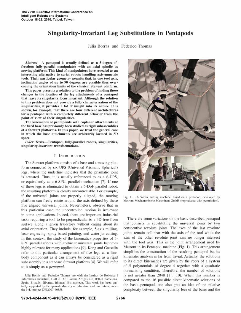
Fig. 1. A 5-axis milling machine, based on a pentapod, developed byMetrom Mechatronische Maschinen GmbH (reproduced with permission).
There are some variations on the basic described pentapod
that consists in substituting the universal joints by two
consecutive revolute joints. The axes of the last revolute
joints remain collinear with the axis of the tool while the
axis of the other revolute joint axis no longer intersect
with the tool axis. This is the joint arrangement used by
Metrom in its Pentapod machine (Fig. 1). This arrangement
simplifies the construction of the resulting pentapod but its
kinematic analysis is far from trivial. Actually, the solutions
to its direct kinematics are given by the roots of a system
of 5 polynomials of degree 4 together with a quadratic
normalizing condition. Therefore, the number of solutions
is not greater than 2048 [1], [10]. When this number is
compared to the 16 possible direct kinematic solutions of
the basic pentapod, one also gets an idea of the relative
complexity between the singularity loci of the basic and the
The 2010 IEEE/RSJ International Conference on Intelligent Robots and Systems October 18-22, 2010, Taipei, Taiwan
978-1-4244-6676-4/10/$25.00 ©2010 IEEE 2766
modified design.
In this paper, we concentrate ourselves in the analysis
of the singularities of the basic design which, despite its
practical interest, has received little attention in the past.
Indeed, most of the related previous works deal with the
case in which the spherical joints are coplanar. For example,
Zhang and Song solved the forward kinematics problem for
the coplanar case showing that it can have up to 8 assembly
modes [11]. Husty and Karger studied the conditions for a
pentapod with coplanar spherical joints to be architecturally
singular [3]. More recently, Borràs and Thomas analyzed the
role of cross-ratios between the location of the leg attach-
ments in the characterization of architectural singularities,
and in singularity-invariant architectural changes, also for the
coplanar case [2].
The characterization of the singularities of spatial parallel
mechanisms is, in general, a difficult task. To obtain this
characterization, we will follow an indirect approach: we will
find those changes in the location of the leg attachments of
a pentapod that leave its singularity locus invariant.
Even when there is no known solution to a given math-
ematical problem, it is always possible to try to find the
set of transformations to the problem that leave its solution
invariant. Although this does not solve the problem itself, it
provides a lot of insight into its nature. This way of thinking
is at the root of the development of Group Theory and it is the
one applied herein for the characterization of the singularity
loci of pentapods.
The paper is organized as follows. The next section
presents a new formulation for the characterization of the sin-
gularities of a pentapod. Section III presents a solution to the
problem of changing the location of the attachments of one of
the legs of the pentapod without altering its singularity locus.
Section IV shows that there are four different architectures
for a pentapod attending to the characteristics of the possible
locations for the base attachment of the new leg in these
singularity-invariant leg substitutions. Section V presents
three examples corresponding to three different architectures.
Finally, Section VII summarizes the main contributions.
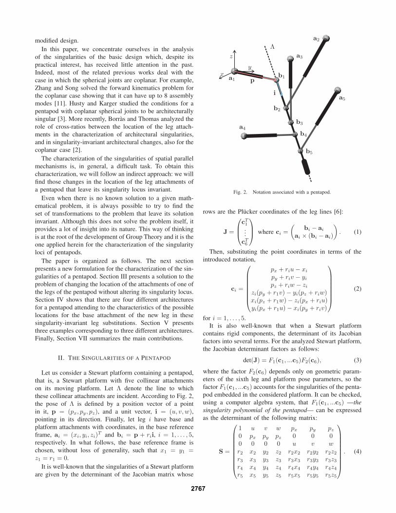
II. THE SINGULARITIES OF A PENTAPOD
Let us consider a Stewart platform containing a pentapod,
that is, a Stewart platform with five collinear attachments
on its moving platform. Let Λ denote the line to which
these collinear attachments are incident. According to Fig. 2,
the pose of Λ is defined by a position vector of a point
in it, p = (px, py, pz), and a unit vector, i = (u, v, w),pointing in its direction. Finally, let leg i have base and
platform attachments with coordinates, in the base reference
frame, ai = (xi, yi, zi)T and bi = p + rii, i = 1, . . . , 5,
respectively. In what follows, the base reference frame is
chosen, without loss of generality, such that x1 = y1 =z1 = r1 = 0.
It is well-known that the singularities of a Stewart platform
are given by the determinant of the Jacobian matrix whose
p
i
xy
z
a1
a2
a3
a4
a5
b1
b2
b3
b4
b5
Λ
Fig. 2. Notation associated with a pentapod.
rows are the Plücker coordinates of the leg lines [6]:
J =
cT1
...
cT6
where ci =
(
bi − ai
ai × (bi − ai)
)
. (1)
Then, substituting the point coordinates in terms of the
introduced notation,
ci =
px + riu − xi
py + riv − yi
pz + riw − zi
zi(py + r1v) − yi(pz + riw)xi(pz + r1w) − zi(px + riu)yi(px + r1u) − xi(py + riv)
(2)
for i = 1, . . . , 5.
It is also well-known that when a Stewart platform
contains rigid components, the determinant of its Jacobian
factors into several terms. For the analyzed Stewart platform,
the Jacobian determinant factors as follows:
det(J) = F1(c1, ...c5)F2(c6), (3)
where the factor F2(c6) depends only on geometric param-
eters of the sixth leg and platform pose parameters, so the
factor F1(c1, ...c5) accounts for the singularities of the penta-
pod embedded in the considered platform. It can be checked,
using a computer algebra system, that F1(c1, ...c5) —the
singularity polynomial of the pentapod— can be expressed
as the determinant of the following matrix:
S =
1 u v w px py pz
0 px py pz 0 0 00 0 0 0 u v w
r2 x2 y2 z2 r2x2 r2y2 r2z2
r3 x3 y3 z3 r3x3 r3y3 r3z3
r4 x4 y4 z4 r4x4 r4y4 r4z4
r5 x5 y5 z5 r5x5 r5y5 r5z5
. (4)
2767

This is a very convenient representation of the singularities
of a pentapod because the first three rows depend only on
its pose and the remaining four, on the coordinates of the
attachments.
Let S denote the 4×7 matrix formed by the last four rows
of S. Since the coefficients of the singularity polynomial of
the pentapod are the 4 × 4 minors of this matrix, we can
conclude this section with the following two observations:
1) If S is rank defective, the pentapod will always be
singular irrespective of its leg lengths. In other words,
it will be architecturally singular [5].
2) If one of the four rows of S is substituted by another
row linearly dependent on these four row vectors, the
resulting matrix will have the same 4×4 minors up to
a constant multiple. This observation will allow us, in
the next section, to obtain leg substitutions that leave
the pentapod singularities invariant.
III. SINGULARITY-INVARIANT LEG SUBSTITUTIONS
We are interested in substituting leg i by another leg with
base and platform attachment coordinates a = (x, y, z)T and
b = pT + riT , respectively. Next, we deduce the conditions
that (x, y, z, r) must satisfy to leave the singularities of the
pentapod unaltered. To this end, consider the matrix
P =
r2 x2 y2 z2 r2x2 r2y2 r2z2
r3 x3 y3 z3 r3x3 r3y3 r3z3
r4 x4 y4 z4 r4x4 r4y4 r4z4
r5 x5 y5 z5 r5x5 r5y5 r5z5
r x y z rx ry rz
(5)
and take (x, y, z, r) such that P is rank defective. Then,
we can substitute any row in S by (r, x, y, z, rx, ry, rz) so
that all the 4 × 4 minors of the resulting matrix will be
equal to those of S up to a constant multiple. Hence, the
corresponding singularity polynomial will be also the same,
up to a constant factor. In other words, if any of the legs of
the analyzed pentapod is substituted by another leg whose
attachments coordinates are defined by a set of values for
(x, y, z, r) that make P rank defective, the singularity locus
of the pentapod will remain unchanged.
If Gaussian Elimination is applied on P1, the last row of
the resulting matrix is:
1
P567
(
0 0 0 0 0 P67 P57 P56
)
,
where Pij is the determinant of the matrix obtained from P
after removing the columns i and j, and Pijk the determinant
of the matrix formed by the first four rows of P after
removing the columns i, j and k. Then, assuming that
1Gaussian Elimination uses elementary row operations to reduce a givenmatrix into a rank-equivalent one, with an upper triangular shape. Then,rank deficiency occurs when all the elements of the last row are zero.
P567 6= 0, P is rank defective if, and only if,
P67 =
∣
∣
∣
∣
∣
∣
∣
∣
∣
∣
r2 x2 y2 z2 r2x2
r3 x3 y3 z3 r3x3
r4 x4 y4 z4 r4x4
r5 x5 y5 z5 r5x5
r x y z rx
∣
∣
∣
∣
∣
∣
∣
∣
∣
∣
= 0
P57 =
∣
∣
∣
∣
∣
∣
∣
∣
∣
∣
r2 x2 y2 z2 r2y2
r3 x3 y3 z3 r3y3
r4 x4 y4 z4 r4y4
r5 x5 y5 z5 r5y5
r x y z ry
∣
∣
∣
∣
∣
∣
∣
∣
∣
∣
= 0
P56 =
∣
∣
∣
∣
∣
∣
∣
∣
∣
∣
r2 x2 y2 z2 r2z2
r3 x3 y3 z3 r3z3
r4 x4 y4 z4 r4z4
r5 x5 y5 z5 r5z5
r x y z rz
∣
∣
∣
∣
∣
∣
∣
∣
∣
∣
= 0
(6)
Since this system is linear in x, y, and z, it can be
rewritten, after cofactor expansion, in matrix form as:(
P267 − P567r −P367 P467
P257 −P357 − P567r P457
P256 −P356 P456 − P567r
)(
x
y
z
)
=
(
P167r
P157r
P156r
)
,
(7)
whose solution, using Crammer’s rule, yields:{
x =f1(r)
f(r), y =
f2(r)
f(r), z =
f3(r)
f(r)
}
, (8)
where f(r), f1(r), f2(r) and f3(r) are cubic polynomials in
r. Thus, it can be concluded that all singularity-invariant leg
substitutions will be defined by a correspondence between
points on Λ and points on a cubic space curve attached to
the base.
IV. DEGENERATE CASES
In this section, we analyze the case in which the determi-
nant of the linear system (7) is null, i.e., the case in which
the solutions given by (8) are undefined because f(r) = 0.
In this case, two situations arise:
1) System (7) is consistent. One of the equations can be
discarded and, for a given value of r, infinitely many
solutions can be found for (x, y, z) which correspond
to points of a line (as they correspond to the intersec-
tion of two planes).
2) System (7) is inconsistent. It represents a system of
three parallel planes.
If the determinant of the linear system (7) is null, the
system is consistent if, and only if, f1(r) = 0, f2(r) = 0, or
f3(r) = 0. Let us suppose that r0 is a real root of f(r) = 0that makes the system consistent. Then, if one of the platform
attachments of the new leg is placed at b0 = p + r0i, the
corresponding base attachment can be placed at any point on
the corresponding line in the base. This situation is interest-
ing to build reconfigurable robots where the attachments can
be rearranged on actuated guides following the singularity-
invariant lines. This allows the manipulator to reconfigure
2768

itself for different tasks, increasing its useful workspace and
maintaining the singularities always at the same location.
TABLE I
THE 4 POSSIBLE ARCHITECTURES FOR A PENTAPOD
Number of consistent Base attachment locusreal roots
0 1 cubic curve
1 1 line and 1 plane conic
2 3 non-concurrent lines
3 3 concurrent lines
We can classify the possible architectures of a pentapod
depending on the number of real roots of f(r) = 0 that lead
to a consistent linear system. Depending on this number, the
cubic curve obtained for the general case degenerates into
a plane conic curve and a line, or a set of lines. Table I
summarizes the different possibilities.
V. EXAMPLES
A. Generic Case: No Consistent Real Roots
TABLE II
COORDINATES OF THE ATTACHMENTS, ai = (xi, yi, zi) AND
bi = p + rii, FOR A PENTAPOD WITH GENERIC ARCHITECTURE
i xi yi zi ri
1 0 0 0 02 6 0 10 13 13 10 12 34 9 16 7 55 −3 16 3 7
Consider the pentapod with the attachment coordinates in
table II. Substituting them in (7), we get(
288r − 6612 6306 5676−3136 288r + 3904 35201076 −2306 288r − 1484
)(
x
y
z
)
=
(
18816r
16384r
−5504r
)
,
(9)
whose determinant is 2654208(9r3 − 131r2 − r − 1365).The roots are 15.22, −0.33+3.14i, and −0.33− 3.14i. The
evaluation of system (9) for r = 15.22 yields an inconsistent
linear system. As a consequence, the base attachment locus
for a leg substituting any of the legs of the analyzed pentapod
that would leave its singularity locus invariant is a cubic.
Solving (9) using Crammer’s rule gives
x =12r(49r2 − 240r − 553)
9r3 − 131r2 − r − 1365,
y =256r(−23r + 2r2 + 21)
9r3 − 131r2 − r − 1365,
z =−4r(−880r + 4557 + 43r2)
9r3 − 131r2 − r − 1365.
(10)
Fig. 3 shows the manipulator and the cubic curve defined
by these equations. All legs in gray satisfy the correspon-
dence between r and (x, y, z) through the above curve
parameterization, so any of the original pentapod legs can be
substituted by any of these legs in gray without modifying
the singularity locus of the analyzed pentapod.
Fig. 3. In general, a singularity-invariant leg substitution is defined bya 1-1 correspondence between the points on the moving platform and thepoints on a cubic attached to the base. Some candidates for a leg substitutionappear in gray.
B. Degenerate Case: Three Consistent Real Roots
TABLE III
COORDINATES OF THE ATTACHMENTS, ai = (xi, yi, zi) AND
bi = p + rii, FOR A PENTAPOD WITH DEGENERATE ARCHITECTURE
i xi yi zi ri
1 0 0 0 02 0 0 0 23 2 2 −2 44 4 −4 −4 55 0 −4 −4 6
Consider the pentapod with the attachment coordinates in
Table III. Substituting them in (7), we get
2304 − 512r −128 128−256 2688 − 512r 384256 384 2688 − 512r
x
y
z
= 0
(11)
whose determinant is −134217728(r − 5)(r − 6)(r − 4).All the roots are real and make the system consistent. This
system has the trivial solution x = y = z = 0 for any value
of r. In other words, any leg can be substituted, without
modifying the singularities of the analyzed pentapod, by any
other with attachments located at (0, 0, 0) in the base and
anywhere in the moving platform.
Now, consider one of the above roots, for example r = 4.
2769

s
a3 a4
a5
a1 = a2
b1
b2
b3
b4
b5
(a)
a1
a2
a3a4
a5
b1
b4
b5
b2 = b3
(b)
a3 a4
a5
a1 = a2
b1
b4
b5
b2 = b3
(c)
Fig. 4. Example of a pentapod with degenerate architecture. In this case thecubic curve degenerates into three lines. The base attachments can be movedalong these lines without modifying the singularity locus of the pentapod(a). This permits coalescing two attachments in the moving platform (b), ortwo attachments in the base and the platform at the same time (c).
The substitution of this value in (11) yields
2x − y + z = 02x − 5y − 3z = 02x + 3y + 5z = 0
which is a consistent linear system. That is, the three plane
equations intersect at the same line. Solving this system for
x and y leads to a parametrization of such line: {(x, y, z) |x = −t, y = −t, z = t, t ∈ R}. Proceeding in a similar
way for the other two roots, we obtain two more line
parameterizations. Summarizing, we have four solution sets,
namely:
s1 = {(x, y, z, r) | r = 4, x = −t, y = −t, z = t, t ∈ R}s2 = {(x, y, z, r) | r = 5, x = t, y = −t, z = t, t ∈ R}s3 = {(x, y, z, r) | r = 6, x = 0, y = t, z = t, t ∈ R}s4 = {(x, y, z, r) | r = t, x = 0, y = 0, z = 0, t ∈ R}
In Fig. 4-(a), the legs in gray have attachments whose
coordinates are in one of the above solution sets. The
legs with platform attachments coordinates b3, b4 and b5
correspond to solutions in s1, s2 and s3, respectively. The
solution set s4 corresponds to legs with base attachment at
(0, 0, 0) and platform attachment anywhere in the moving
platform line.
Several equivalent manipulators, from the point of view of
their singularities, can be obtained by substituting only leg 2.
For example, in Fig. 4-(b), this leg has been substituted by a
leg whose attachments coordinates are in s1. Its attachments
are a2 = (4, 4,−4) and b2 = p+4i, thus making coincident
b2 and b3. In Fig. 4-(c), leg 2 has been substituted by a leg
whose attachments coordinates are in s4. In this case, the new
attachments have coordinates a2 = (0, 0, 0) and b2 = p+4ithus making coincident a1 with a2, and b2 with b3.
If actuated guides are placed on the lines defined by s1, s2,
and s3, the manipulator can reconfigure its base attachments
following singularity-invariant leg rearrangements. This in-
creases its usable workspace because, though singularities
remain unchanged, its stiffness does change at each recon-
figuration, so that it can be optimized for each specific task
at different regions of the workspace.
C. Degenerate Case: One Consistent Real Root
TABLE IV
COORDINATES OF THE ATTACHMENTS, ai = (xi, yi, zi) AND
bi = p + rii), FOR A PENTAPOD WITH DEGENERATE ARCHITECTURE
i xi yi zi ri
1 0 0 0 0
2 −2 2√
3 −1 1
3 −9 4√
3 −3 34 −8 0 −1 5
5 −6 −2√
3 0 7
Consider the pentapod with the attachment coordinates in
Table IV. Substituting them in (7), we get
2770

Fig. 5. One consistent real root results in a base attachment locus formedby a line and a conic.
√3(−18r + 70) 84 40
√3
−144 18√
3(1 − r) 7220
√3 24
√3(50 − 18r)
(
x
y
z
)
=
(
24r√
3216r
−24r√
3
)
.
(12)
The solution of the above system, obtained using Crammer’s
rule, is
x =−4r(r + 11)
3r2 − 14r + 35,
y =−12r(r − 5)
√3
3r2 − 14r + 35,
z =4r(r − 7)
3r2 − 14r + 35.
(13)
which corresponds to a conic parameterized in r.
The determinant of system (12) is −5832√
3(3r2 − 14r +35)(r−3). The only real root is r = 3. After evaluating (12)
for this real root, a consistent degenerate system is obtained
whose solution is:{
r = 3, x = t − 6, y = −2(t − 3)√
3
3, z = t
}
, (14)
which corresponds to a line parameterized in t.
In summary, the locus of the base attachments consists of
a line and a conic (see Fig. 5).
VI. CONCLUSIONS
In this paper, we have introduced a new representation
of the singularity polynomial of a pentapod. This new
expression reveals to be very convenient because, among
other properties, it allows to easily define leg substitutions
that keep singularities invariant.
Although finding singularity-invariant leg substitutions
does not solve the problem of characterizing the singularities
themselves, it provides a lot of insight into its geometric
nature. In this context, the obtained leg substitutions are of
practical interest for two main reasons:
1) If the singularity locus of the pentapod at hand has
already been characterized, it could be interesting to
modify the location of its legs to optimize some other
characteristics without altering such locus.
2) If the singularity locus of the analyzed pentapod has
not been characterized yet, it could be of interest to
simplify its geometry by changing the leg attachment
locations, as it has been shown in the example pre-
sented in Section V-B, thus easing the task of obtaining
this characterization.
We have also shown that for any pentapod there is an
intrinsic correspondence between the points on the moving
platform line and the points on a cubic curve placed on the
fixed base. This characterization permits to study degenerate
cases that present interesting practical applications.
REFERENCES
[1] G. F. Bär and G. Weiß, “Kinematic analysis of a pentapod robot,"Journal for Geometry and Graphics, Vol. 10, No. 2, pp. 173-182, 2006.
[2] J. Borràs and F. Thomas, “Kinematics of line-plane subassemblies inStewart platforms," Proc. of the 2009 IEEE Int. Conf. on Robotics and
Automation, pp. 4094-4099, 2009.[3] M.L. Husty and A. Karger, “Self-Motions of Griffis-Duffy Type Parallel
Manipulators," Proc. IEEE Intl. Conf. on Robotics and Automation, pp.7-12, 2000.
[4] X. Kong and C.M. Gosselin, “Generation and Forward DisplacementAnalysis of Two New Classes of Analytic 6-SPS Parallel Manipulators,"Journal of Robotic Systems, Vol. 18, No. 6, pp. 295-304, 2001.
[5] O. Ma and J. Angeles, “Architecture singularities of platform manipu-lators,” Proc. IEEE Intl. Conf. on Robotics and Automation, vol. 2, pp.1542–1547, 1991.
[6] J.-P. Merlet, “Singular configurations of parallel manipulators and grass-mann geometry,” International Journal of Robotics Research, vol. 8,no. 5, pp. 45–56, 1989.
[7] J-P. Merlet, Parallel Robots, Springer, 2000.[8] R. Neugebauer, M. Schwaar, St. Ihlenfeldt, G. Pritschow, C. Eppler,
and T. Garber, “New approaches to machine structures to overcome thelimits of classical parallel structures," CIRP Annals - Manufacturing
Technology, Vol. 51, No. 1, pp. 293-296, 2002.[9] M. Wecka and D. Staimera, “Parallel kinematic machine tools. Current
state and future potentials," CIRP Annals - Manufacturing Technology,Vol. 51, No. 2, pp. 671-683, 2002.
[10] G. Weiß and G.F. Bär, “Singularity investigation of a 5-leg millingrobot," EuCoMeS, 1st European Conference on Mechanism Science,Obergurgl, Austria, 2006.
[11] C. Zhang and S.M. Song, “Forward kinematics of a class of parallel(Stewart) platforms with closed-form solutions," Proc. IEEE Intl. Conf.
on Robotics and Automation, pp. 2676-2681, 1991.
2771