>/s >/& x dz s > t - denver international...
TRANSCRIPT
LIVE LIFE. TRAVEL WELL.Design Standards ManualLife Safety SystemsDenver Internaonal AirportAirport Infrastructure Management
Life Safety Design Standards Manual
March 2018 ii Denver International Airport
Copyright ©1989-2018 by Denver International Airport, City and County of Denver
All rights reserved
No part of this manual may be reproduced or transmitted in any form or by any means, electronic or mechanical, including photocopying, recording, or by any information storage and retrieval system, without the permission in writing from the publisher.
Released March 2018
Printed in the United States of America

Life Safety Design Standards Manual Table of Contents
March 2018 iii Denver International Airport
Table of Contents Chapter 1 - General ................................................................................................................................................. 11
Section 100 - Overview ........................................................................................................................................ 11 Section 101 - Common Terminology ................................................................................................................... 11 Section 102 - System Design ............................................................................................................................... 12 Section 103 - System Definitions ......................................................................................................................... 12
103.1 Emergency Communication System ....................................................................................... 12 103.2 Fire Detection and Alarm Systems ......................................................................................... 12 103.3 Emergency Alarm Systems ..................................................................................................... 12 103.4 Fire Protection Systems .......................................................................................................... 12 103.5 Smoke Control Systems ......................................................................................................... 12
Section 104 - Deferred Design ............................................................................................................................. 13 Chapter 2 - Emergency Communication Systems .................................................................................................. 15
Section 200 - Emergency Communication Systems ............................................................................................ 15 200.1 Scope ...................................................................................................................................... 15 200.2 Criteria ..................................................................................................................................... 15 200.3 Drawing Requirements ........................................................................................................... 15 200.4 Design Analysis Requirements ............................................................................................... 16 200.5 More Stringent Document Provision ....................................................................................... 16 200.6 Ambient Noise Levels ............................................................................................................. 16
Section 201 - Microphone Stations ...................................................................................................................... 16 Section 202 - Loudspeakers ................................................................................................................................ 16 Section 203 - Amplifiers ....................................................................................................................................... 17 Section 204 - Central Controls ............................................................................................................................. 17 Section 205 - Visual Notification .......................................................................................................................... 17 Section 206 - ECS/Fire Alarm Interface ............................................................................................................... 18 Section 207 - ECS Operational Plan.................................................................................................................... 18
207.1 Introduction ............................................................................................................................. 18 207.2 Presignal Operation ................................................................................................................ 18
Section 208 - Sequence of Operation .................................................................................................................. 19 208.1 Building Definition ................................................................................................................... 19 208.2 Fire Alarm Automatic Sequence – AOB, CUP, and AGTS Maintenance ............................... 19 208.3 Fire Alarm Automatic Sequence – HTC Levels 5 – 15 ........................................................... 20 208.4 Fire Alarm Manual Sequence – Terminal, Concourses A, B, and C, and HTC Levels 1 - 4 .. 20 208.5 Emergency Evacuation Manual Sequence ............................................................................. 21 208.6 Media Shunt ............................................................................................................................ 21
Section 209 - Evacuation Activation .................................................................................................................... 22 Section 210 - Fire Alarm System Notification Appliances.................................................................................... 22
210.1 ECS / Paging System Notification Appliances ........................................................................ 22 Section 211 - ECS Operation ............................................................................................................................... 23
211.1 System Description ................................................................................................................. 23 211.2 System Interface ..................................................................................................................... 24 211.3 Live Voice Messages .............................................................................................................. 24 211.4 Prerecorded Messages ........................................................................................................... 26 211.5 Supplemental Textual Messages ............................................................................................ 27 211.6 Tornado Warning or Sighted Manual Sequence ..................................................................... 30 211.7 Non-Emergency Manual Sequence ........................................................................................ 31 211.8 Live Voice Announcements Only ............................................................................................ 31
Section 212 - ECS Messages .............................................................................................................................. 32 212.1 ECS Message Sequence of Operations ................................................................................. 32 212.2 Prerecorded ECS Messages .................................................................................................. 33 212.3 Video Textual Messages ......................................................................................................... 35 212.4 Fire Alarm LED Text Messaging Appliances .......................................................................... 37
Life Safety Design Standards Manual Table of Contents
March 2018 iv Denver International Airport
Section 213 - ECS Screens ................................................................................................................................. 38 213.1 TSW Prerecorded Message Screen ....................................................................................... 38 213.2 ECS System Live Voice Selection .......................................................................................... 39 213.3 ECS/Fire Alarm Interface ........................................................................................................ 39
Section 214 - ECS Maintenance .......................................................................................................................... 40 214.1 System Addition or Alteration .................................................................................................. 40 214.2 Inspection and Maintenance ................................................................................................... 41
Chapter 3 - Fire Alarm Systems .............................................................................................................................. 43 Section 300 - Fire Detection and Alarm System .................................................................................................. 43 Section 301 - Scope ............................................................................................................................................. 43 Section 302 - System Description ........................................................................................................................ 43 Section 303 - Criteria ........................................................................................................................................... 43 Section 304 - Drawing Requirements .................................................................................................................. 43 Section 305 - Design Analysis Requirements ...................................................................................................... 44 Section 306 - More Stringent Document Provisions ............................................................................................ 44 Section 307 - Initiating Devices ............................................................................................................................ 44
307.1 Addressable Heat Detectors ................................................................................................... 44 307.2 Addressable Smoke Detectors ............................................................................................... 44 307.3 Addressable Manual Stations ................................................................................................. 44 307.4 Addressable Monitor Modules ................................................................................................ 44 307.5 Fire Pump Supervision ............................................................................................................ 45
Section 308 - Notification Devices ....................................................................................................................... 45 308.1 Audible Alarms ........................................................................................................................ 45 308.2 Visual Alarms .......................................................................................................................... 45 308.3 Audible/Visual Notification ...................................................................................................... 46 308.4 Textual Visual Notification ....................................................................................................... 47 308.5 Fire Alarm Loudspeaker Appliance ......................................................................................... 47
Section 309 - Fire Safety Functions ..................................................................................................................... 47 309.1 Clean Agent Release .............................................................................................................. 47 309.2 HVAC Shutdown ..................................................................................................................... 47 309.3 Door Release .......................................................................................................................... 48 309.4 Elevator Recall ........................................................................................................................ 48 309.5 Media Shunt ............................................................................................................................ 48
Section 310 - System Configuration .................................................................................................................... 48 310.1 Circuit Supervision .................................................................................................................. 48 310.2 Circuit Survivability .................................................................................................................. 48 310.3 Power Supply .......................................................................................................................... 48 310.4 Graphic Annunciation .............................................................................................................. 48 310.5 System Configuration .............................................................................................................. 48 310.6 Network Communications ....................................................................................................... 49
Chapter 4 – Emergency Alarm Systems ................................................................................................................. 51 Section 400 - Scope ............................................................................................................................................. 51 Section 401 - Criteria ........................................................................................................................................... 51 Section 402 - Related Work ................................................................................................................................. 51 Section 403 - Drawing Requirements .................................................................................................................. 51 Section 404 - Design Analysis Requirements ...................................................................................................... 51 Section 405 - More Stringent Provisions.............................................................................................................. 52 Section 406 - System Requirements ................................................................................................................... 52 Section 407 - Beverage Dispensing CO2 Emergency Alarm Systems ............................................................... 52
407.1 Alarm Set Points ..................................................................................................................... 52 Section 408 - Inert Gas Emergency Alarm Systems ........................................................................................... 53
408.1 Alarm Set Points ..................................................................................................................... 53 Section 409 - Mechanical Ventilation ................................................................................................................... 53

Life Safety Design Standards Manual Table of Contents
March 2018 v Denver International Airport
Chapter 5 - Fire Protection Systems ....................................................................................................................... 55 Section 500 - General .......................................................................................................................................... 55 Section 501 - Related Work ................................................................................................................................. 55 Section 502 - Drawing Requirements .................................................................................................................. 55 Section 503 - Fire Protection Systems (Terminal and Concourse Areas) ........................................................... 55
503.1 Airport Terminal and Concourse Buildings ............................................................................. 55 503.2 Parking Garages ..................................................................................................................... 55 503.3 Baggage Handling Areas ........................................................................................................ 56 503.4 Other Facilities ........................................................................................................................ 56
Section 504 - Miscellaneous Requirements ........................................................................................................ 56 504.1 Standpipe System ................................................................................................................... 56 504.2 Kitchen Hood Systems ............................................................................................................ 56 504.3 Hydrants .................................................................................................................................. 56 504.4 Water Supply ........................................................................................................................... 56 504.5 Pressure Reducing Valves ...................................................................................................... 56 504.6 Foam Systems ........................................................................................................................ 57 504.7 Coordination with Smoke Control Zones ................................................................................ 57
Chapter 6 - Smoke Control Systems ....................................................................................................................... 59 Section 600 - General .......................................................................................................................................... 59
600.1 Related Work .......................................................................................................................... 59 600.2 Quality Assurance ................................................................................................................... 59 600.3 Drawing Requirements ........................................................................................................... 59
Section 601 - Design Criteria ............................................................................................................................... 59 601.1 Standards ................................................................................................................................ 59 601.2 General ................................................................................................................................... 60 601.3 Equipment ............................................................................................................................... 60 601.4 Equipment/Zone Identification ................................................................................................ 60 601.5 Design Criteria ........................................................................................................................ 60 601.6 Transfer Air ............................................................................................................................. 61 601.7 Smoke Zone and Airflow Diagrams ........................................................................................ 61 601.8 System Initiation ...................................................................................................................... 61
Section 602 - Terminal Smoke Control Operation Overview ............................................................................... 61 602.1 Great Hall ................................................................................................................................ 61 602.2 Levels 5 and 6 Ticketing, Baggage Claim, and Tenant Areas ................................................ 62 602.3 Level 4 Train Platform ............................................................................................................. 62 602.4 Levels 3 and 4 Mechanical Equipment, Baggage Handling, and Baggage Make-up ............. 62 602.5 Level 1 Offices ........................................................................................................................ 62 602.6 Vertical Pressurization ............................................................................................................ 62
Section 603 - North Terminal Smoke Control Operation Overview ..................................................................... 62 603.1 Level 5, 6, and 7 International, Domestic, and Customs Areas .............................................. 62 603.2 Level 4 Offices and Communications Areas ........................................................................... 63 603.3 Level 3 Baggage Tunnels ....................................................................................................... 63
Section 604 - Passenger Bridge Smoke Control Operation Overview ................................................................ 63 604.1 Exhaust ................................................................................................................................... 63 604.2 Pressurization ......................................................................................................................... 63
Section 605 - AOB Smoke Control Operation Overview ..................................................................................... 63 Section 606 - Concourse A Smoke Control Operation Overview ........................................................................ 64
606.1 Center Core and International Smoke Control Zones ............................................................. 64 606.2 Subcore, Holdroom, and International Walkway Smoke Control Zones ................................. 64 606.3 Basement Smoke Control Zones ............................................................................................ 64 606.4 Tenant Space Smoke Control Zones ...................................................................................... 64 606.5 Control Tower .......................................................................................................................... 64
Section 607 - Concourse B Smoke Control Operation Overview ........................................................................ 64

Life Safety Design Standards Manual Table of Contents
March 2018 vi Denver International Airport
607.1 Center Core Smoke Control Zones ......................................................................................... 65 607.2 Subcore and Holdroom Smoke Control Zones ....................................................................... 65 607.3 Basement Smoke Control Zones ............................................................................................ 65 607.4 Tenant Space Smoke Control Zones ...................................................................................... 65 607.5 Control Tower .......................................................................................................................... 65
Section 608 - Concourse C Smoke Control Operation Overview ........................................................................ 65 608.1 Center Core Smoke Control Zones ......................................................................................... 66 608.2 Subcore Smoke Control Zones ............................................................................................... 66 608.3 Basement Smoke Control Zones ............................................................................................ 66 608.4 Tenant Space Smoke Control Zones ...................................................................................... 66 608.5 Control Tower .......................................................................................................................... 66
Section 609 - AGTS Tunnel Smoke Control Operation Overview ....................................................................... 66 Section 610 - CUP Smoke Control Operation Overview ..................................................................................... 66 Section 611 - HTC Smoke Control Operation Overview ...................................................................................... 66 Section 612 - Construction Documents ............................................................................................................... 67 Section 613 - Smoke Control System Testing ..................................................................................................... 67
613.2 Renovation Work ..................................................................................................................... 67 Chapter 7 - Passenger Loading Bridge Requirements............................................................................................ 69
Section 700 - Overview ........................................................................................................................................ 69 Section 701 - Scope ............................................................................................................................................. 69 Section 702 - Criteria ........................................................................................................................................... 69 Section 703 - Ventilation ...................................................................................................................................... 69 Section 704 - Fire Alarm Requirements for PLBs ................................................................................................ 69 Section 705 - ECS Requirements for PLBs ......................................................................................................... 69

Life Safety Design Standards Manual Table of Figures
March 2018 vii Denver International Airport
Table of Figures Figure 1- Typical Ceiling Loudspeaker with ECS Indicator ..................................................................................... 22 Figure 2 - Typical FID Bank ..................................................................................................................................... 27 Figure 3 - Typical FID Bank ..................................................................................................................................... 27 Figure 4 - Concourse A, 2x5 Advertising Video Display .......................................................................................... 28 Figure 5 - Concourse B, 2x5 Advertising Video Display .......................................................................................... 28 Figure 6 - NFPA Visual Character Height Requirements ........................................................................................ 30 Figure 7 - Great Hall Large Video Advertising Displays .......................................................................................... 30 Figure 8 - TSW ECS Control Screen ....................................................................................................................... 38 Figure 9 - IED Paging Panel (A Panel) and Digital Microphone Station ................................................................. 39 Figure 10 - Fire Alarm/ECS Interface Cabinet ......................................................................................................... 39 Figure 11- Typical ALERT Strobes .......................................................................................................................... 46 Figure 12 - Typical LED Text Messaging Appliance ............................................................................................... 47 Figure 13- Terminal Complex .................................................................................................................................. 49
Table of Tables Table 1- Measured Average Ambient Noise Levels ................................................................................................ 16 Table 2 - NFPA 72 ADA Sign Requirement ............................................................................................................ 29 Table 3 - AOB, CP, AGTS Maintenance ECS Sequence of Operations ................................................................. 32 Table 4 - Concourses and Terminal ECS Sequence of Operations ........................................................................ 32 Table 5 - Westin Hotel and Transit Center ECS Sequence of Operations.............................................................. 33 Table 6 - Inert Gas Maximum Storage Amounts ..................................................................................................... 52 Table 7 - Smoke Control Equipment Identification .................................................................................................. 60

This Page Intentionally Blank
Life Safety Design Standards Manual Preface
March 2018 ix Denver International Airport
Preface The Denver International Airport (DEN) Design Standards have been developed to ensure a unified and consistent approach to the thematic and technical design for DEN. These standards are for use and strict implementation by all Consultants under contract to DEN, to Tenants, and all other Consultants under contract to any other entity for the design of projects at DEN.
The Standards Manuals are intended to be working documents, which are revised and updated, as required, to address the general, conceptual, design, and technical standards for all areas of design for the DEN.
This Design Standards Manual for the Denver International Airport has been prepared for use by competent, professionally licensed Architectural and Engineering Consultants under the direction of DEN Maintenance and Engineering or Tenants of DEN.
The Design Standards shall not be quoted, copied, or referenced in any bidding or construction Contract Documents. All information contained in these standards must be fully explained and shown in all bidding and Contract Documents.
The Design Standards Manuals are intended to be used as a whole, as each manual is complimentary to the others. In order to understand the overall thematic and design standards for DEN, the manuals must be utilized together and not separated from the Design Standards Manuals as a whole.
Information added to this Design Standards Manual since the previous publication is shown in red. The Consultant shall not reproduce, duplicate in any manner, transmit to other consultants or other entities or use in conjunction with other projects without the express written consent of DEN.
NOTE: This document is optimized for duplex (double-sided) printing.

This Page Intentionally Blank

Life Safety Design Standards Manual Chapter 1 - General
March 2018 11 Denver International Airport
Chapter 1 - General
Section 100 - Overview The life safety systems for all facilities at DEN are to be based on the use of proven design techniques. These techniques shall utilize existing, readily available equipment and components. Designs shall conform to the design criteria listed herein, with the highest priority being the safety, well-being, and comfort of the traveling public.
Systems must be serviceable, maintainable and at the same time provide flexibility for future addition and modification. All equipment installation, including all the components, must be accessible for testing, adjustment and maintenance.
Airport facilities are dynamic. Life safety systems are designed such that changes, additions, and modifications to facilities take place to adapt to changing business needs. Systems will need to be altered to accommodate these changes.
Life cycle cost valuation and first costs are important considerations throughout the design process from concept to final design and through construction.
Section 101 - Common Terminology The following terms are used throughout this DSM:
Concourse Refers to the buildings where all passenger boarding and deplaning activities take place. DEN has three concourses: A, B, and C.
Fixed Walkway An enclosed, fixed connector that extends from an airport concourse gate to a loading bridge for allowing passengers aircraft/concourse access without direct exposure to the elements.
Hotel and Transit Center (HTC) The HTC is located at the south end of the Jeppesen Terminal. The HTC consists of the following three areas:
• The Westin hotel and conference center. • The outdoor plaza connecting the hotel to the Jeppesen Terminal on Level 5. • The RTD train platform and public transit center.
Jet Bridge, Jetway, or Loading Bridge An enclosed, movable connector that extends from an airport concourse gate or fixed walkway to an aircraft allowing passengers.
Modules (Mods) Both the Jeppesen Terminal and the Concourse Buildings are segmented into building modules for the purposes of systems organization.
Node A fire alarm panel, graphic workstation, or other device on the fire alarm network that is responsible for network communication.
Terminal Complex The Terminal Complex is the main complex of buildings at DEN. The Terminal Complex includes, including:
• The Jeppesen Terminal, north terminal, and parking garages. • The Airport Office Building (AOB).

Life Safety Design Standards Manual Chapter 1 - General
March 2018 12 Denver International Airport
• The Central Utility Plant (CUP). • Concourses A, B, and C. • Automated Guideway Transit System (AGTS) and baggage tunnels. • HTC.
Section 102 - System Design Life safety systems are an integral part of DEN operations. When modifying existing spaces, or constructing new spaces, the designer shall consider the impact of all aspects of the design on life safety systems. The designer shall consider indirect impacts to the systems listed in Section 103, including, but not limited to the following:
• Changes in occupancy type.
• Reconfiguration of walls and/or spaces.
• Installation of bulky or noisy equipment that may affect visual or audible notification.
• Multimedia installations in public areas, such as dynamic advertising displays.
Section 103 - System Definitions The Life Safety Design Standards Manual (DSM) contains design guidelines for the following systems:
• Emergency Communication System (ECS).
• Fire Detection and Alarm Systems.
• Emergency Alarm System.
• Fire Protection Systems.
• Smoke Control Systems.
103.1 Emergency Communication System The ECS installed in the Terminal Complex is comprised of a network of audio loudspeakers, as well as visual textual notification systems. The ECS, together with the Fire Alarm System, provides audible and visual mass notification during emergency events.
103.2 Fire Detection and Alarm Systems Fire detection and alarm systems are utilized to provide automatic smoke and fire detection, as well as mass visual notification during emergency events. The Terminal Complex utilizes a networked Fire Alarm System with central controls, and operates in conjunction with the ECS. DEN facilities that are outside the Terminal Complex are typically furnished with Fire Detection and Alarm Systems.
103.3 Emergency Alarm Systems Emergency alarm systems are utilized to provide indication and warning of emergency situations involving hazardous materials. DEN uses these systems for beverage dispensing, inert gas applications and in certain compressed gas storage applications.
103.4 Fire Protection Systems Fire protection systems are installed within facilities to mitigate the extent of fire damage and to maximize occupant survivability during emergency events. Many DEN facilities and specialty areas are provided with various types of fire protection systems.
103.5 Smoke Control Systems Smoke control systems are installed within the Terminal Complex to remove smoke from occupied areas, to enable occupants to exit to a safe area and minimize smoke-related hazards during emergency events.

Life Safety Design Standards Manual Chapter 1 - General
March 2018 13 Denver International Airport
Section 104 - Deferred Design As of February 2018, deferred design submittals in Contract Documents for Life Safety systems are no longer allowed. All portions of Life Safety Systems contained within this manual shall be fully designed, detailed, and specified in the Contract Documents.
END OF CHAPTER

This Page Intentionally Blank
Life Safety Design Standards Manual Chapter 2 - Emergency Communication Systems
March 2018 15 Denver International Airport
Chapter 2 - Emergency Communication Systems
Section 200 - Emergency Communication Systems
200.1 Scope This chapter provides design guidance to the Engineer in the area of the ECS, which is utilized for both emergency communication and public address (PA) messaging at DEN. General criteria are set forth, as well as drawing and design analysis requirements.
200.2 Criteria ECS shall be an In-building Mass Notification System as defined by National Fire Protection Act (NFPA) 72. Specifically, DEN Fire Alarm signaling operates on a Presignal function in accordance with NFPA 72 - 2010 (23.8.1.2) for public buildings. This function disables the automatic operation of the notification appliances; thereby, requiring manual initiation for an evacuation. The Presignal/manual evacuation function shall be utilized in public airport terminal buildings (i.e., the Terminal, HTC Levels 1 – 4, and Concourses A, B, and C). Presignal shall not be utilized in the HTC Levels 5 – 15, AOB, CUP, or the AGTS Maintenance Facility, as these facilities continue to operate with automatic notification actuation.
The Fire Alarm System mostly relies on the PA system manufactured by Innovative Electronic Designs, Inc. (IED) for the audible portion of the ECS. Fire alarm horns are only installed where ambient sound levels prohibit achieving intelligible voice messaging. Intelligibility of the ECS is considered acceptable if at least 90 percent of the measurement locations within each space have a measured Speech Transmission Index (STI) of not less than 0.45 (0.65 Common Intelligibility Scale (CIS)) and an average STI of not less than 0.50 STI (0.70 CIS).
The requirements contained in this chapter are based upon the Federal Communications Commission (FCC) rules and regulations, the Electronic Industries Association (EIA) publications, IEEE standards, the NFPA codes, and the ANSI standards. Specific requirements for the ECS come from this document as well as the appropriate sections of the International Building Code (IBC) and International Fire Code (IFC) as currently adopted and amended by the City and County of Denver. Note that in the 2016 Denver Amendments to the IBC, Appendix S has specific requirements for airports, which are in addition to all other referenced standards.
The ECS Design Consultant shall be an acoustical consultant experienced in the design of similar systems, for similar type facilities. The ECS shall provide fire alarm alert tones, evacuation signals, and live voice announcements, both for emergency and normal business operations. The entire system shall be in accordance with the codes and standards referenced in this chapter.
200.3 Drawing Requirements The Design Consultant shall include all ECS requirements in the Contract Documents. As a minimum, the drawings shall illustrate the following:
A. A single-line diagram depicting all control panels, input devices, amplifiers, loudspeakers, horns, and telephone and Fire Alarm System interfaces. The diagram shall show the paging zone to which each device or group of devices is connected.
B. Floor plans shall show the location of all control panels, amplifiers, loudspeakers, and other devices.
C. Preliminary single-line diagrams shall be provided with the schematic design review documents. At this stage, zone designations and wiring information need not be presented.
D. Preliminary floor plans shall be provided with the Design Development Review Documents. At this stage, zone designations and wiring information need not be presented.
E. ECS features may be combined on common floor plans with other electrical or special system designs for each facility. Input device and control panel locations should be shown, as well as typical loudspeaker layouts for each functional type of space in the facility.
F. DEN Master Diagrams shall be updated and returned to the DEN Electrical Engineer at the Issue for Construction and Record Document phases.

Life Safety Design Standards Manual Chapter 2 - Emergency Communication Systems
March 2018 16 Denver International Airport
200.4 Design Analysis Requirements The Design Consultant shall include the following in the Design Analysis Report (DAR):
A. Substantiation of the ECS design, indicating the origin of specific facility ECS requirements.
B. The rated area of coverage for the type of loudspeakers used, as well as calculations indicating the audible sound pressure throughout the space.
C. Power required from each loudspeaker and amplifier sizing.
D. Catalog cuts of each selected equipment type.
E. Calculations that verify the power rating of the amplifiers.
F. For any acoustically distinguishable space with ceilings greater than 15 feet high, acoustic modeling of sound system performance including sound pressure level (SPL) distribution and predicted intelligibility.
200.5 More Stringent Document Provision Should there be a conflict among the requirements presented in this document and the documents referenced above; the Design Consultant shall comply with the more stringent requirements.
200.6 Ambient Noise Levels Any areas with an ambient noise level exceeding the maximum sound level as specified by NFPA 72, shall be provided with supplemental means of notification (i.e., visual). The Designer shall perform SPL measurements within the work area during normal occupancy to determine the actual ambient noise level. The following table of approximate ambient noise levels shall be used as a reference in PA system design.
Table 1- Measured Average Ambient Noise Levels
Measured Average Ambient Noise Levels Application Sound Level AGTS Tunnel 80 dBA Baggage Tunnel 80 dBA Mechanical Room 78 dBA Holding areas 63 dBA Retail space 63 dBA Computer room 70 dBA Office 52 dBA Restaurant 71 dBA Lobbies 60 dBA Hotel room 52 dBA
Section 201 - Microphone Stations All Fire Command Centers are furnished with ECS microphone stations and graphical user interfaces to select paging zones. In addition, all microphone stations shall meet the following requirements:
• All new microphone stations shall be IP-based, connected via Ethernet to the ECS network.
• Microphone stations in the Fire Command Center and in Airport Operation Centers shall be capable of emergency level live voice announcements throughout the Terminal Complex.
Section 202 - Loudspeakers The Design Consultant shall ensure that:

Life Safety Design Standards Manual Chapter 2 - Emergency Communication Systems
March 2018 17 Denver International Airport
• The contract provides an elevation view showing loudspeaker mounting height, spacing, and the angle of dispersion; shows calculations to verify the power delivered to the loudspeakers; and provide catalog cuts of the typical manufacturers data shall be provided in the DAR.
• The ECS design uses a distributed loudspeaker system or line array layout as determined by the acoustical design.
• The design hearing height shall be 5 feet above the floor in general areas and 4 feet above the floor where permanent seating is provided.
• The ECS shall be designed to deliver PA announcements at 10 dBA above the design ambient noise level, and emergency announcements at the level specified in NFPA 72.
• PLBs containing fixed walkways in excess of 100 feet in length shall be provided with intelligible ECS loudspeaker coverage, in its own zone, throughout the entire fixed walkway.
Section 203 - Amplifiers Amplifier system design shall be modular, made up of 2-channel, 400-watt plug-in, replaceable modules or dual channel line driver module. The system shall be configured so that loss of any one module card does not appreciably interrupt system performance. New amplifiers shall be of the same manufacturer as the existing system.
Section 204 - Central Controls Each building in the Terminal Complex has computer-based central controllers. Central controls are located in the Communications Rooms in each building. New central controllers shall only be added as directed by the DEN Electrical Engineer.
Central controls shall:
• Provide microprocessor-based programmable controls to allow maximum flexibility for the ECS.
• Allow any microphone station to be programmed so that it is capable of addressing any or all zones.
• Queue access requests into each paging zone to allow access in turn.
The Announcement Control System (ACS) shall:
• Manage announcements and messages using routed data on a standard Ethernet Network.
• Manage dynamic requests for live and delayed announcements, prerecorded and assembled messages, actions, defined events, and two-way full duplex intercom connections.
• Provide assignable priority levels to announcements so high priority emergency announcements may interrupt lower priority announcements.
• Require two levels of password security to protect system programming assignments.
• Provide programmed automatic daily testing of the entire PA system.
Systems used for Fire Alarm annunciation shall:
• Provide automatic testing compatible with NFPA 72.
• When implemented in public areas, provide automatic gain control to compensate for transient, ambient noise
Devices that are critical to system operation shall be monitored, and any failures shall trigger a supervisory notification indicated in the Fire Alarm Control Panel (FACP).
Section 205 - Visual Notification The ECS system is supplemented visually by the Flight Information Displays (FIDs), Gate Information Displays (GIDs), Baggage Information Displays (BIDs), and other displays, which provide textual messaging. This concept is referred to as visible textual notification in NFPA 72.

Life Safety Design Standards Manual Chapter 2 - Emergency Communication Systems
March 2018 18 Denver International Airport
LED text messaging appliances are installed in baggage tunnel and tug ramp areas. These devices may be required in high ambient noise environments.
Visual displays that are not used for ECS textual messaging may be required to be shunted to remove distraction during emergency events. Consult the DEN Electrical Engineer to determine requirements.
Section 206 - ECS/Fire Alarm Interface The ECS shall:
• Provide the capability of prioritizing and broadcasting a 70-volt audio signal from the Fire Alarm System.
• Provide the capability of sending microphone-level audio signal to the Fire Alarm System.
Note: Fire alarm announcements shall always take precedence over PA announcements.
Section 207 - ECS Operational Plan
207.1 Introduction Denver International Airport (DEN) has implemented a robust and comprehensive Emergency Communication System (ECS) throughout the major buildings on the DEN campus. This includes the HTC, Jeppesen Terminal (Main and North Terminal), AOB, CUP, Concourse A, Concourse B, Concourse C, and the AGTS Maintenance Facility. This system has been progressively implemented from 2011 – 2016 in conjunction with the airports Public Safety Notification Upgrade (PSNU) and Fire Alarm Replacement Projects. Simultaneously, the HTC was built and appropriate system interfaces were designed and implemented.
This plan provides a detailed review of system operation, infrastructure, interfaces, messages, and maintenance requirements. This document is based on previously issued documents including the “Emergency Communication System Migration Plan” (Revision 1 dated March 14, 2012) and the “Emergency Communication System Implementation Plan” (Revision 6.4 dated September 13, 2013). The information contained herein is considered ancillary to the “Fire Alarm Replacement Project Design Analysis Report” (Revision 2.0, dated June 22, 2011, Final revision pending), and supplements the findings of the “Emergency Communication System Risk Analysis”, Revision 1.0, dated September 21, 2011.
The operation of the DEN ECS has been implemented in close consultation with DFD. This includes the documentation and approval of PSNU Administrative Modification #2 and #8, and multiple plan reviews and permit issuance and acceptance. The system has also been implemented in accordance with the 2010 Edition of NFPA 72©, National Fire Alarm and Signaling Code, which is the Code of Record per PSNU Administrative Modification #1.
This document supports the DEN Fire Alarm System Replacement Project, which provides fire alarm protection and emergency communication for the DEN Complex. The scope of the project was the complete replacement of the Fire Alarm System in the integrated DEN Complex, which includes the Main Terminal Building, three passenger Concourses (A, B, and C), AOB, CUP, and the AGTS Maintenance Facility. The replacement Fire Alarm System is the primary means of audible notification for both fire and non-fire emergencies and the only system that can initiate textual visual messaging. The Simplex TrueSite Workstations (TSWs) are used to initiate all emergency communication messages. The Simplex equipment interfaces directly with the Multi-User Flight Information Display (MUFID) Software (Com-Net System) to initiate textual visual messaging on flight displays and appropriate electronic advertising video displays.
With the DEN ECS, when DFD or DEN Operations deem that in the interest of public safety an announcement shall be made, trained personnel shall activate either a prerecorded message or conduct a live announcement via a microphone to one, several, or all areas within the Complex. In addition to broadcasting the message, primary visual notification (i.e., strobes) in the affected areas shall activate during emergency relocation announcements and remain activated until an all-clear announcement is made or the signal is cancelled. The ECS is supplemented visually by FIDs, GIDs, BIDs, and other appropriate video displays, which provide textual visual messaging.
207.2 Presignal Operation DFD and DEN Operations has implemented a Presignal Function in accordance with NFPA 72 - 2010 (23.8.1.2) for public buildings. This function disables the automatic operation of the notification appliances, thereby requiring
Life Safety Design Standards Manual Chapter 2 - Emergency Communication Systems
March 2018 19 Denver International Airport
manual initiation for an evacuation. The Presignal/manual evacuation function shall be utilized in public airport terminal buildings (i.e., the Terminal, HTC Levels 1 – 4, and Concourses A, B, and C). Presignal shall not be utilized in the HTC Levels 5 – 15, AOB, CUP, or the AGTS Maintenance Facility, as those facilities continue to operate with automatic notification actuation.
In accordance with presignal requirements, any automatic alarm shall be immediately transmitted to DFD for emergency response, even though building notification is not initiated.
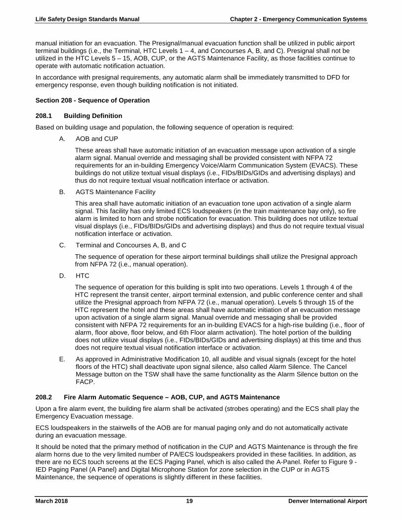
Section 208 - Sequence of Operation
208.1 Building Definition Based on building usage and population, the following sequence of operation is required:
A. AOB and CUP
These areas shall have automatic initiation of an evacuation message upon activation of a single alarm signal. Manual override and messaging shall be provided consistent with NFPA 72 requirements for an in-building Emergency Voice/Alarm Communication System (EVACS). These buildings do not utilize textual visual displays (i.e., FIDs/BIDs/GIDs and advertising displays) and thus do not require textual visual notification interface or activation.
B. AGTS Maintenance Facility
This area shall have automatic initiation of an evacuation tone upon activation of a single alarm signal. This facility has only limited ECS loudspeakers (in the train maintenance bay only), so fire alarm is limited to horn and strobe notification for evacuation. This building does not utilize textual visual displays (i.e., FIDs/BIDs/GIDs and advertising displays) and thus do not require textual visual notification interface or activation.
C. Terminal and Concourses A, B, and C
The sequence of operation for these airport terminal buildings shall utilize the Presignal approach from NFPA 72 (i.e., manual operation).
D. HTC
The sequence of operation for this building is split into two operations. Levels 1 through 4 of the HTC represent the transit center, airport terminal extension, and public conference center and shall utilize the Presignal approach from NFPA 72 (i.e., manual operation). Levels 5 through 15 of the HTC represent the hotel and these areas shall have automatic initiation of an evacuation message upon activation of a single alarm signal. Manual override and messaging shall be provided consistent with NFPA 72 requirements for an in-building EVACS for a high-rise building (i.e., floor of alarm, floor above, floor below, and 6th Floor alarm activation). The hotel portion of the building does not utilize visual displays (i.e., FIDs/BIDs/GIDs and advertising displays) at this time and thus does not require textual visual notification interface or activation.
E. As approved in Administrative Modification 10, all audible and visual signals (except for the hotel floors of the HTC) shall deactivate upon signal silence, also called Alarm Silence. The Cancel Message button on the TSW shall have the same functionality as the Alarm Silence button on the FACP.
208.2 Fire Alarm Automatic Sequence – AOB, CUP, and AGTS Maintenance Upon a fire alarm event, the building fire alarm shall be activated (strobes operating) and the ECS shall play the Emergency Evacuation message.
ECS loudspeakers in the stairwells of the AOB are for manual paging only and do not automatically activate during an evacuation message.
It should be noted that the primary method of notification in the CUP and AGTS Maintenance is through the fire alarm horns due to the very limited number of PA/ECS loudspeakers provided in these facilities. In addition, as there are no ECS touch screens at the ECS Paging Panel, which is also called the A-Panel. Refer to Figure 9 - IED Paging Panel (A Panel) and Digital Microphone Station for zone selection in the CUP or in AGTS Maintenance, the sequence of operations is slightly different in these facilities.

Life Safety Design Standards Manual Chapter 2 - Emergency Communication Systems
March 2018 20 Denver International Airport
A. Live Voice Activation
For live voice announcements, the user shall utilize the ECS Paging Microphone Station.
B. Alarm Silence
1. Selecting the Cancel Message button on the TSW (AOB only) shall deactivate the playing of the prerecorded message. This shall deactivate all strobes and textual messages.
2. Alternatively, selecting the Alarm Silence button on the FACP or TSW shall deactivate the playing of the prerecorded message and all strobes and textual messages.
C. System Reset
Selecting the System Reset button on the FACP or TSW shall return the Fire Alarm System to normal and stop all messages that have automatically been activated (assuming all devices are no longer in an alarm condition and have returned to normal status).
208.3 Fire Alarm Automatic Sequence – HTC Levels 5 – 15 Upon a fire alarm event, the building fire alarm shall be activated (strobes operating) and the ECS shall be playing an Emergency Evacuation message. Notification activation shall be on the floor of alarm, floor above the alarm, floor below the alarm and the sixth floor (main lobby), typical of a high-rise voice Fire Alarm System.
Fire alarm loudspeakers in the stairwells and elevator cabs of the HTC are for manual paging only and do not automatically activate during an evacuation message. There are available selection switches located on the Simplex FACP in the Level 1 Fire Command Center or the FACP in the Terminal Level 6 Southwest Fire Command Center.
It should be noted that the loudspeakers provided on Levels 1 – 5 of the HTC are controlled and powered by the IED Paging System. Loudspeakers on Levels 6 – 15 of the HTC are controlled and powered by the Simplex Fire Alarm System. The system has been integrated so that an announcement made on one system can be heard with loudspeakers on the other system.
A. Live Voice Activation
For live voice announcements, the user shall utilize any of the ECS Paging Panels/A-Panel for zone selection and the IED Digital Microphone Station or the Simplex Microphone Station. Simplex microphone availability is limited to the Level 1 Fire Command Center and the Terminal Level 6 Southwest Fire Command Center.
B. Alarm Silence
1. Selecting the Cancel Message button on the TSW shall deactivate the playing of the prerecorded message. This shall also deactivate all strobes and textual messages.
2. Alternatively, selecting the Alarm Silence button on the FACP or TSW shall also deactivate the playing of the prerecorded message. At DFD request, the strobes in the hotel portion of the HTC shall continue to operate after Alarm Silence has been activated.
C. System Reset
Selecting the System Reset button on the FACP or TSW shall return the Fire Alarm System to normal and stop all messages that have automatically been activated (assuming all devices are no longer in an alarm condition and have returned to normal status) and shall deactivate strobes in the hotel portion of the HTC.
208.4 Fire Alarm Manual Sequence – Terminal, Concourses A, B, and C, and HTC Levels 1 - 4 Upon a fire alarm event the fire department shall arrive with the building FA/ECS in a standby mode. The fire alarm event shall be annunciated on the FACP and TSW. The incident commander shall decide on whether and when to activate emergency notification.
A. Fire Alarm under Investigation Activation
If notification to building occupants regarding a fire is desired but an evacuation is not determined to be necessary, the following shall be activated:

Life Safety Design Standards Manual Chapter 2 - Emergency Communication Systems
March 2018 21 Denver International Airport
1. On the TSW, select the Fire under Investigation message. The message shall play building wide and shall include textual notification. No strobes shall activate and the message times-out automatically after three rounds.
B. Emergency Evacuation Activation
If building evacuation is determined to be necessary, evacuation (i.e., Emergency Evacuation prerecorded message, all strobes building wide, and Evacuation textual messages) can be initiated by any one of the following:
1. On the TSW, select the Emergency Evacuation button.
2. Blue manual evacuation station in FCC.
C. Live Voice Activation
For live voice announcements, the user shall utilize the ECS Paging Panel/A-Panel for zone selection and the IED Digital Microphone Station.
D. Alarm Silence
1. Selecting the Cancel Message button on the TSW shall deactivate the prerecorded message playing. This shall also deactivate all strobes and textual messages.
2. Alternatively, selecting the Alarm Silence button on the FACP or TSW shall deactivate the prerecorded message playing and all strobes and textual messages.
E. System Reset
Selecting the System Reset button on the FACP or TSW shall return the Fire Alarm System to normal. System Reset shall not alter non-FA/ ECS messages initiated on the TSW.
208.5 Emergency Evacuation Manual Sequence Upon a non-fire emergency event, the building FA/ECS shall be in standby mode. The incident commander shall decide as to whether and when to activate emergency notification.
The sequence for an Emergency Evacuation is the same as the Fire Alarm Manual Sequence above, except that no fire alarm has occurred in the building. In addition, it would not be anticipated that the System Reset button on the FACP or TSW would be utilized in this sequence.
208.6 Media Shunt The Fire Alarm System provides media shunt function in Tenant spaces throughout the complex, as well as select visual displays throughout the public space. When a Tenant has a private hard-wired audio and/or video system, the system shall be shunted (i.e., power removed) to allow the emergency audible message to be heard over the ECS loudspeakers and any significant visual distractions removed. The fire alarm control module that provides media shunt shall activate anytime an emergency message sequence is activated.
A. Audio Shunt
1. The primary means of audio shunt within Tenant spaces shall be by a fire alarm control module that provides media shunt. This module shall activate anytime an emergency message sequence is activated by removing 120 VAC power from the electrical outlet that such devices are connected.
2. As an alternative, an audio sensing relay can provide media shunt function. The audio sensing relay provided on the IED loudspeaker circuit shall activate anytime an emergency message is active and shall be arranged to remove 120 VAC power from the electrical outlet that such Tenant audio devices are connected.
B. Visual Shunt
1. The Fire Alarm System provides a shunt of all public cable television (CATV) feeds at key CATV distribution points in the Terminal, Concourse A, Concourse B, Concourse C, and the Hotel. The fire alarm control module shall remove the CATV feed during an active emergency message sequence by removing power from the central distribution hub in the area.

Life Safety Design Standards Manual Chapter 2 - Emergency Communication Systems
March 2018 22 Denver International Airport
2. Select advertising video displays and digital directory displays shall shunt anytime an emergency message is activated. Refer to Section 214 - ECS Maintenance for more information. This is accomplished using a fire alarm control module that removes power to the select device or devices.
Section 209 - Evacuation Activation Once DEN Operations, DFD, or other authority deem that in the interest of public safety an evacuation is required, there are two ways to activate an evacuation:
1. On each TSW, there is an ECS control screen. This screen is easily accessed from the Home site plan screen. Once on the ECS control screen, there is an Emergency Evacuation activation button for each building. Once selected, the emergency evacuation sequence of operations is activated. If the button is selected a second time (toggled), the sequence is deactivated.
2. In each Fire Command Center (total of eight in the complex), there is a single Manual Evacuation Station. When activated, this initiates the emergency evacuation sequence of operations for that specific building only. Once activated, the blue evacuation station button is reset by turning the mushroom switch until it releases. However, to deactivate the emergency evacuation sequence, a System Reset shall be initiated via the local FACP or the TSW System Reset screen.
This functionality enables an evacuation to be initiated remotely, usually from the AOB 10th Floor Operations Center, or locally from the Fire Command Center. The Manual Evacuation Station is provided for local operation in case the TSW is compromised or non-functional, or if the evacuation needs to be initiated very quickly.
Once activated, the emergency evacuation sequence is initiated building-wide as noted above.
Section 210 - Fire Alarm System Notification Appliances The Simplex Fire Alarm System shall control and power strobe appliances labeled ALERT, combination horn/strobe appliances labeled ALERT, and LED text messaging appliances. Refer to Section 308 - Notification Devices.
210.1 ECS / Paging System Notification Appliances The Fire Alarm System relies entirely on the IED Paging System for audible ECS notification in all but a select few locations.
The IED Paging System uses commercial-grade loudspeakers to provide adequate audibility and intelligibility throughout all spaces with paging system coverage. Paging loudspeakers and circuits are zoned for routine airport paging as well as emergency paging consistent with the ECS sequence of operation. Loudspeakers placed in Tenant finish areas and non-public areas are provided with a sticker on the front surface of the loudspeaker that states Fire Alarm Do Not Disconnect to prevent tampering. Refer to Figure 1- Typical Ceiling Loudspeaker with ECS Indicator.
Figure 1- Typical Ceiling Loudspeaker with ECS Indicator

Life Safety Design Standards Manual Chapter 2 - Emergency Communication Systems
March 2018 23 Denver International Airport
Notification devices (i.e., loudspeakers) are in each of the main complex buildings in areas where intelligible audio reproduction can be accomplished. There are loudspeakers in some parking structures and passenger pickup/drop-off areas (i.e., curbside), AGTS tunnels, most mechanical and electrical rooms, as well as all office and public space. These devices range from small coaxial in-ceiling loudspeakers, industrial horn-type loudspeakers used in harsh environments, and large-format line array-type loudspeaker units used in the Terminal Great Hall and HTC RTD train platform to achieve intelligibility in difficult acoustic environments. Loudspeakers located in public spaces are controlled by an ambient noise system that samples the average sound levels in a space and adjusts the output volume to achieve consistent audio coverage.
Section 211 - ECS Operation
211.1 System Description The ECS system consists of the IED Globalcom Suite of hardware and software providing audible voice coverage throughout the DEN Complex. The system relies on a distributed data network of controllers, digital microphones, and amplifiers. The system uses industry hardened network standards for audio transmission over TCP/IP networks utilizing both RTP (Real Time Protocol) and Cirrus Logic Cobranet audio transport. The integrity of the network is maintained by the DEN Technologies/Life Safety department. There is a dedicated backbone and distribution system of switches for the IED audio traffic separate from the typical users' network (enterprise). This data network is a redundant class A network. This network model allows greater control, monitoring, and notification both for fault notifications as well as emergency messaging. The system can reproduce a single audio input source to every loudspeaker in the network, approximately 15,000 loudspeakers simultaneously. There is some control of the zoning available to the user allowing the selection of part of the building, most of the building or all buildings for live voice announcements.
IED titan amplifier frames have eight (8) available amplifier card slots with a ninth automatic failover backup amplifier card. Each card is capable of two channels of 200w of audio, or one single channel. The redundant amplifier switches over automatically upon amplifier card failure providing a redundant backup. Most loudspeakers in the airport have been taped to 2w, which would allow about 80 loudspeakers with headroom per channel. These loudspeaker zone circuits are piped and zoned from the original install of the airport, with new modification made to add coverage to all spaces for the PSNU project.
The IED system receives via a dry contact closure signal from the Simplex system to capture all zones of loudspeakers and accepts audio from Simplex to play over all zones in the local building. This happens in five buildings during an emergency weather message, as each building has separate activation into the IED system. The IED system also provides a fault relay into the Simplex Fire Alarm System to notify of any large system outages that substantially affect the operation of the paging system. If a large area of coverage is down due to a titan frame dropping offline, an ECS Critical trouble is sent to the TSW for reporting.
A. IEC Globalcom System
The IED Globalcom system is also responsible for the normal voice reproduction functions for the airport, including courtesy announcements, regulated prerecorded messages for airport security, and Airline daily operations. The fire alarm audio feed and live voice announcements from the FCC microphone station take priority, interrupting any other audio playing through the system.
The microphone stations in Fire Command Centers and Operations Centers have special authority allow emergency level paging. These are the same microphone units found at all gates and ticket counters with different programming to allow emergency level control of the paging system.
Globalcom provides an ambient sound analysis system that monitors the ambient level of the sound in a space, and if it is outside of the threshold, the system automatically increases or decreases the level of the loudspeakers in that zone accordingly. This system allows better intelligibility in a space by providing accurate SPLs during normal activities, as well as abnormal activities, by actively attenuating the level. These sensors are provided in all public spaces in the Terminal Complex. The system has been equalized and setup to provide at a minimum 85dB of audio during most reasonable activities. This system is limited in the amount of gain allowed to keep overall levels within acceptable ranges.

Life Safety Design Standards Manual Chapter 2 - Emergency Communication Systems
March 2018 24 Denver International Airport
B. Com-Net Video System
The Com-Net video system is responsible for visual textual messages during alarm conditions. This system consists of approximately 1,500 video displays in the MUFIDS system and approximately 100 advertising displays. These displays utilize the Com-Net distributed video content system that allows for server controlled display content to be dynamically changed. During an alarm event, the typical Airlines content from most of these monitors is captured and switched to an emergency message pertinent to the alarm selected on the TSW. The screen capture system has multiple components required to make it work. There is a virtual server running as the director for the system responsible for command and control (C&C) sending signals out to network connected computers to trigger the switch.
When the Simplex Fire Alarm System triggers an alarm, Com-Net accepts one of eight relay contact closures in the black box via an analog-to-digital USB device, which notifies a PC in the local building. Refer to Figure 10 - Fire Alarm/ECS Interface Cabinet. This computer reports to the C&C server to initiate an emergency message. The C&C server then activates all the computers located behind each monitor via a network command with the correct message to display.
For non-MUFID screens (i.e., advertising displays), a network signal is sent to an RS-232 device (print server) to switch the display to an emergency message. The print server sends an RS-232 command to switch the input of the DVI switch located at the monitor. The second input of this DVI switch is connected to the emergency DDC computer by Com-Net. This DDC also receives a network signal to display the correct message on screen.
211.2 System Interface The operation of, and integration with, the Fire Alarm System and the PA/ECS (provided by IED) and MUFID Software (provided by Com-Net) systems forms the overall life safety system that allows fire detection, emergency response, and occupant notification. As such, the operation of these systems shall be intuitive and simple for all users during an emergency, and the interface between the systems shall be reliable and supervised.
To achieve this, the following system configuration is supported:
1. Fire Alarm/Emergency Communication (FA/ECS) shall be accomplished through the TSW as the primary emergency system user interface.
2. The Simplex Fire Alarm System shall provide audio output of prerecorded emergency messages as outlined below to the IED System.
3. The paging zone interface between the Fire Alarm System and the PA/ECS and MUFID systems shall be limited to supervised dry contact connections.
• The interface between MUFID and Airline-owned or commercial advertising displays entails four (4) unsupervised electronic devices and software. As such, use of these interfaces is limited to areas where additional supplemental visual notification is required.
4. The Fire Alarm System shall activate visual notification devices (i.e., Fire Alarm System alert strobes) and textual visual notification devices (i.e., LED text message signs and visual textual notification via MUFIDs (FIDs, BIDs, and GIDs)). Text message signs have pre-determined messages as noted later in this document.
5. Direct activation of the ECS Paging Panel/A-Panel for zone selection and the IED Digital Microphone Station shall be used for live voice paging.
6. The PA/ECS provides a trouble/fault contact to the Fire Alarm System (1 per interface, total of five) upon any critical trouble/fault that renders a portion of the PA/ECS inoperable.
211.3 Live Voice Messages The most effective method of audible notification is a live message from a recognized authority figure (e.g., Fire Chief, Chief of Police, head of security, etc.). Additionally, the message should provide concise information about the event and provide clear instructions for building occupants with frequent follow up messages to update occupants.
Life Safety Design Standards Manual Chapter 2 - Emergency Communication Systems
March 2018 25 Denver International Airport
Additionally, it was recommended that the message be announced on a building-wide basis to ensure that a consistent message is provided to all occupants. This is important, as most areas of the buildings are not separated, and the occupants are highly transient. By way of example, a family might split up, with some members remaining at the gate area, while others walk to another part of the concourse to shop. (It should be noted, however, that the IED Paging System zoning still allows for notification of select locations within each building in an emergency, although such notification would not provide the entire breadth of emergency notification as provided by the ECS as described within this document.)
Only prerecorded messages shall be initiated through the TSW via a dedicated ECS Control Screen. TSWs are provided in each Fire Command Center and at Airport Operation Centers. The Fire Alarm System shall ensure that visual notification (both strobes and textual appliances) are activated and deactivated, as appropriate for the event, when audible messages occur. The Fire Alarm System shall activate dry contacts, which shall be inputs into the ECS to activate the prerecorded building-wide emergency announcement overriding any current announcements. Live voice announcements shall utilize the ECS Paging Panel/A-Panel for zone selection and the IED Digital Microphone Station to provide the concise information discussed above.
As a rule, a live voice announcement shall not activate visual notification if it is not already activated, nor shall it deactivate visual notification if it is already activated. Therefore, as noted in the sequence of operations below, when a recognized authority figure makes the decision to conduct an emergency live-voice announcement that requires action by a building occupant (e.g., evacuation or relocation), then it should be standard operating procedure to initiate the most appropriate prerecorded emergency message first, thereby initiating the correct notification appliance activation, followed by initiating a live voice announcement.
A live voice announcement from the ECS Paging Panel/A-Panel for zone selection and the IED Digital Microphone Station shall always be a priority signal over any other prerecorded message of any type. A live voice announcement shall immediately interrupt any existing message being played for the duration of the announcement. DFD has determined that based on the multiple possible scenarios and the ability for the emergency responders to either cancel a message or restart a message on the TSW, it is not appropriate to modify the audio signal that is being sent from the Fire Alarm System to the ECS after microphone activation. As such, no connection (dry contact) is necessary between the ECS and the Simplex system for this purpose.
This live voice priority sequence is accomplished within the ECS with the use of priority levels. The ECS Paging Panel/A-Panel for zone selection and the IED Digital Microphone Station shall be the highest priority microphone (Priority 1) and shall immediately interrupt any existing message being played, including prerecorded messages being supplied by the Fire Alarm System. The Fire Alarm System prerecorded message shall be the second-highest priority signal (Priority 2) and shall immediately interrupt any existing message being played except for a live voice announcement from an ECS Microphone. General paging (normal) messages from the PA system shall be a third level signal (Priority 3) and shall operate and sequence as currently programmed. Fire alarm/ECS test messages shall be a Priority 2 signal so that they can be used to test (mimic) the emergency operation of the system.
A. Live Voice Messages at the HTC
As noted, in all areas of the complex, live voice messages are made using the ECS (IED) Paging Panel Microphone Station and these messages are transmitted over the ECS (IED) loudspeakers. At the HTC, however, IED System loudspeakers are located on Levels 1 – 5 and Simplex system loudspeakers are located on Levels 6 – 15 and in stairwells and elevator cabs. The fire alarm and ECS system have been linked so that a live voice message made from either the IED System microphone or the Simplex system microphone shall be played in select areas of the HTC.
A live voice message made using the ECS (IED) Paging Panel Microphone Station shall play over the Simplex Fire Alarm system loudspeakers on Levels 6 – 15 of the hotel as a single paging zone. The IED System provides a line level audio input to the Simplex Fire Alarm system upon activation of a supervised dry contact that tells the Fire Alarm System to accept the message and override any existing prerecorded message that may be playing. The IED microphone station has seven selection switches for Levels 1, 2, 3, 4, 5, 1-5, and 1-15 All Building.
The Simplex Fire Alarm Control Unit (FACP) in the HTC Fire Command Center (and the backup command center in the Terminal Level 6 Southwest) contains a Simplex microphone with manual selection switches. The Simplex microphone can make manual selective announcements to floors 5 – 15, stairs 1 – 7, and all elevator cabs. Activation of the All Loudspeakers Talk button provides activation of all Simplex loudspeakers. To provide voice messages from Simplex into the ECS (IED
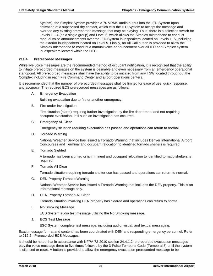
Life Safety Design Standards Manual Chapter 2 - Emergency Communication Systems
March 2018 26 Denver International Airport
System), the Simplex System provides a 70 VRMS audio output into the IED System upon activation of a supervised dry contact, which tells the IED System to accept the message and override any existing prerecorded message that may be playing. Thus, there is a selection switch for Levels 1 – 4 (as a single group) and Level 5, which allows the Simplex microphone to conduct manual voice announcements over the IED System loudspeakers located on Levels 1 -5, including the exterior loudspeakers located on Level 5. Finally, an All Call button is provided to allow the Simplex microphone to conduct a manual voice announcement over all IED and Simplex system loudspeakers located within the HTC.
211.4 Prerecorded Messages While live voice messages are the recommended method of occupant notification, it is recognized that the ability to initiate prerecorded messages on the system is desirable and even necessary from an emergency operational standpoint. All prerecorded messages shall have the ability to be initiated from any TSW located throughout the Complex including in each Fire Command Center and airport operations centers.
It is recommended that the number of prerecorded messages shall be limited for ease of use, quick response, and accuracy. The required ECS prerecorded messages are as follows:
A. Emergency Evacuation
Building evacuation due to fire or another emergency.
B. Fire under Investigation
Fire situation (alarm) requiring further investigation by the fire department and not requiring occupant evacuation until such an investigation has occurred.
C. Emergency All Clear
Emergency situation requiring evacuation has passed and operations can return to normal.
D. Tornado Warning
National Weather Service has issued a Tornado Warning that includes Denver International Airport Concourses and Terminal and occupant relocation to identified tornado shelters is required.
E. Tornado Sighted
A tornado has been sighted or is imminent and occupant relocation to identified tornado shelters is required.
F. Tornado All Clear
Tornado situation requiring tornado shelter use has passed and operations can return to normal.
G. DEN Property Tornado Warning
National Weather Service has issued a Tornado Warning that includes the DEN property. This is an informational message only.
H. DEN Property Tornado All Clear
Tornado situation involving DEN property has cleared and operations can return to normal.
I. No Smoking Message
ECS System audio test message utilizing the No Smoking message.
J. ECS Test Message
ESC System complete test message, including audio, visual, and textual messaging.
Exact message format and content has been coordinated with DEN and responding emergency personnel. Refer to 212.2 - Prerecorded ECS Messages.
It should be noted that in accordance with NFPA 72-2010 section 24.4.1.2, prerecorded evacuation messages play the voice message three to five times followed by the 3-Pulse Temporal Code (Temporal 3) until the system is silenced or reset. A button is provided to allow the emergency evacuation prerecorded message to be
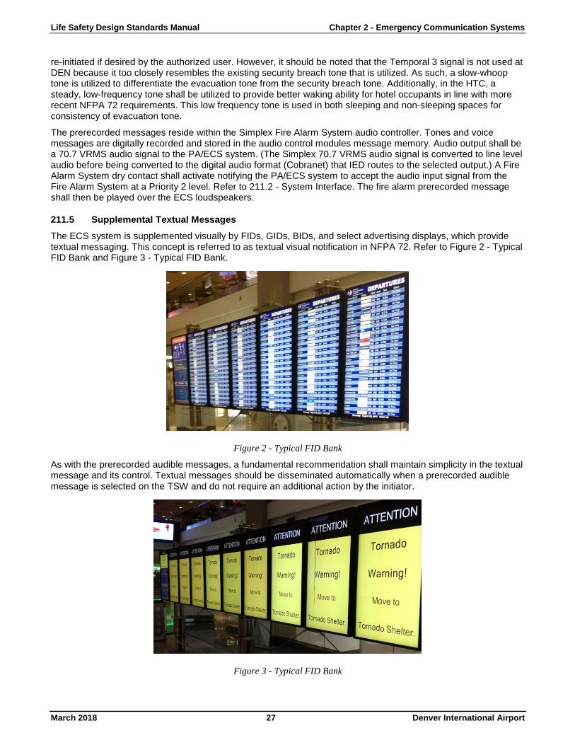
Life Safety Design Standards Manual Chapter 2 - Emergency Communication Systems
March 2018 27 Denver International Airport
re-initiated if desired by the authorized user. However, it should be noted that the Temporal 3 signal is not used at DEN because it too closely resembles the existing security breach tone that is utilized. As such, a slow-whoop tone is utilized to differentiate the evacuation tone from the security breach tone. Additionally, in the HTC, a steady, low-frequency tone shall be utilized to provide better waking ability for hotel occupants in line with more recent NFPA 72 requirements. This low frequency tone is used in both sleeping and non-sleeping spaces for consistency of evacuation tone.
The prerecorded messages reside within the Simplex Fire Alarm System audio controller. Tones and voice messages are digitally recorded and stored in the audio control modules message memory. Audio output shall be a 70.7 VRMS audio signal to the PA/ECS system. (The Simplex 70.7 VRMS audio signal is converted to line level audio before being converted to the digital audio format (Cobranet) that IED routes to the selected output.) A Fire Alarm System dry contact shall activate notifying the PA/ECS system to accept the audio input signal from the Fire Alarm System at a Priority 2 level. Refer to 211.2 - System Interface. The fire alarm prerecorded message shall then be played over the ECS loudspeakers.
211.5 Supplemental Textual Messages The ECS system is supplemented visually by FIDs, GIDs, BIDs, and select advertising displays, which provide textual messaging. This concept is referred to as textual visual notification in NFPA 72. Refer to Figure 2 - Typical FID Bank and Figure 3 - Typical FID Bank.
Figure 2 - Typical FID Bank
As with the prerecorded audible messages, a fundamental recommendation shall maintain simplicity in the textual message and its control. Textual messages should be disseminated automatically when a prerecorded audible message is selected on the TSW and do not require an additional action by the initiator.
Figure 3 - Typical FID Bank

Life Safety Design Standards Manual Chapter 2 - Emergency Communication Systems
March 2018 28 Denver International Airport
It should be noted that primary visual notification for emergencies is achieved using the Fire Alarm Systems visual notification (i.e., ALERT strobes). Such primary visual notification shall be provided specifically to alert those who are deaf or hard of hearing. The use of FIDs, GIDs, BIDs, and select advertising displays are supplementary visual notification. Refer to Figure 4 - Concourse A, 2x5 Advertising Video Display and Figure 5 - Concourse B, 2x5 Advertising Video Display for examples of emergency textual messaging on an advertising display. Such supplementary notification should not be subject to the same prescriptive requirements of primary visual notification, such as supervision, location, and wiring integrity. Since the use of these displays relies on commercial-grade video monitors, network switches, computers, and infrastructure (rather than listed fire alarm equipment), individual video displays may, at times, not capture reliability for a host of reasons. The small risk created by these deficiencies is more than outweighed by the benefit provided by many captured video displays. The use of supplemental textual visual notification provides content-rich messaging which should provide improved response from all occupants (i.e., both hearing and deaf) and can also assist with overcoming disabilities (e.g., hearing, speech recognition, etc.) or language barriers that cannot be easily addressed by audible notification.
Figure 4 - Concourse A, 2x5 Advertising Video Display
Figure 5 - Concourse B, 2x5 Advertising Video Display
A. Textual Message Distribution to FIDs/BIDs/GIDs
The fire alarm interface to MUFID Software (provided by Com-Net) utilizing a dry contact interface is the approach for distributing textual messages to the FIDs/GIDs/BIDs as well as other video displays, like those used for advertising, throughout the airport. With this approach, the message resides on the MUFID server and the fire alarm dry contacts shall be used to notify the system as to
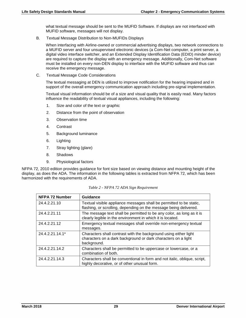
Life Safety Design Standards Manual Chapter 2 - Emergency Communication Systems
March 2018 29 Denver International Airport
what textual message should be sent to the MUFID Software. If displays are not interfaced with MUFID software, messages will not display.
B. Textual Message Distribution to Non-MUFIDs Displays
When interfacing with Airline-owned or commercial advertising displays, two network connections to a MUFID server and four unsupervised electronic devices (a Com-Net computer, a print server, a digital video interface switcher, and an Extended Display Identification Data (EDID) minder device) are required to capture the display with an emergency message. Additionally, Com-Net software must be installed on every non-DEN display to interface with the MUFID software and thus can receive the emergency message.
C. Textual Message Code Considerations
The textual messaging at DEN is utilized to improve notification for the hearing impaired and in support of the overall emergency communication approach including pre-signal implementation.
Textual visual information should be of a size and visual quality that is easily read. Many factors influence the readability of textual visual appliances, including the following:
1. Size and color of the text or graphic
2. Distance from the point of observation
3. Observation time
4. Contrast
5. Background luminance
6. Lighting
7. Stray lighting (glare)
8. Shadows
9. Physiological factors
NFPA 72, 2010 edition provides guidance for font size based on viewing distance and mounting height of the display, as does the ADA. The information in the following tables is extracted from NFPA 72, which has been harmonized with the requirements of ADA.
Table 2 - NFPA 72 ADA Sign Requirement
NFPA 72 Number Guidance 24.4.2.21.10 Textual visible appliance messages shall be permitted to be static,
flashing, or scrolling, depending on the message being delivered. 24.4.2.21.11 The message text shall be permitted to be any color, as long as it is
clearly legible in the environment in which it is located. 24.4.2.21.12 Emergency textual messages shall override non-emergency textual
messages. 24.4.2.21.14.1* Characters shall contrast with the background using either light
characters on a dark background or dark characters on a light background.
24.4.2.21.14.2 Characters shall be permitted to be uppercase or lowercase, or a combination of both.
24.4.2.21.14.3 Characters shall be conventional in form and not italic, oblique, script, highly decorative, or of other unusual form.

Life Safety Design Standards Manual Chapter 2 - Emergency Communication Systems
March 2018 30 Denver International Airport
Figure 6 - NFPA Visual Character Height Requirements
For purposes of utilizing FIDs/BIDs/GIDs, a 3-inch Sans Serif font is recommended. Smaller font size might be acceptable for displays where the viewing distance is less than 30 ft. In the case of larger video displays (e.g., Jumbotron™-type displays), the suggested visual message should be scaled larger as needed to provide legibility from greater distances. The following figure shows an example of emergency messaging on a large video display.
Figure 7 - Great Hall Large Video Advertising Displays
211.6 Tornado Warning or Sighted Manual Sequence DEN Operations staff shall determine whether and when to activate emergency weather/tornado notification. The National Weather Service shall determine if the tornado situation is on the DEN property or directly affects the DEN terminal and concourses. If the tornado situation involves the DEN property, then the Operations Staff shall activate the DEN Property Tornado Warning message, which is informational and shall not require occupant relocation into the identified tornado shelters. If the tornado situation directly involves the DEN terminal and concourses, the Operations Staff shall activate the Tornado Warning or Tornado Sighted messages, which requires occupant evacuation/relocation into the identified tornado shelters. It is anticipated that only Operations Center staff shall activate weather/tornado notification, even though weather/tornado prerecorded messages shall be available on the TSW message selection screen available throughout the campus.
A. DEN Property Tornado Warning Activation
On the TSW, select the Site Wide DEN Property Tornado Warning button. The selected prerecorded message shall play on the ECS loudspeakers. Such notification shall activate complex wide (all buildings, except HTC) and the message shall automatically time out. At the same time, the operator shall select the Hotel DEN Property Tornado Warning button to activate notification within the HTC.

Life Safety Design Standards Manual Chapter 2 - Emergency Communication Systems
March 2018 31 Denver International Airport
B. Tornado Evacuation Activation
On the TSW, select the Tornado Warning or Tornado Sighted button. The selected prerecorded message shall play on the ECS loudspeakers, the strobes connected to the Simplex Fire Alarm System shall activate, and textual visual notification shall display the appropriate tornado textual message. Such notification shall activate complex wide (all buildings, except HTC) and shall continue to operate until cancelled or silenced. At the same time, the operator shall select the Hotel Tornado Warning or Tornado Sighted button to activate notification within the HTC.
C. Live Voice Activation
For live voice announcements, the user shall utilize the ECS Paging Panel/A-Panel for zone selection and the IED Digital Microphone Station typical of the existing condition to provide the concise information discussed above.
D. Alarm Silence
Selecting the Cancel Message button on the TSW shall deactivate the playing of the prerecorded message. This shall also deactivate all strobes and textual messages.
E. System Reset and Fire Alarm Silence
System Reset and FACP Alarm Silence shall not alter non-FA/ECS messages initiated on the TSW.
211.7 Non-Emergency Manual Sequence Select the appropriate non-emergency notification to activate. This would include an Emergency All Clear message, ECS Test message, or any other informational, non-emergency message.
A. Non-Emergency Activation
On the TSW, select the non-emergency message desired. The selected prerecorded message shall play on the ECS loudspeakers building-wide and the visual and textual messaging shall display as indicated in Section 4.1 of this document.
B. Live Voice Activation
For live voice announcements, the user shall utilize the ECS Paging Panel/A-Panel for zone selection and the IED Digital Microphone Station typical of the existing condition to provide the concise information discussed above.
C. Alarm Silence
1. Selecting the Cancel Message button on the TSW shall deactivate the playing of the prerecorded message. This shall also deactivate all strobes and textual messages, if activated.
2. Activating the Cancel Message button on the TSW or the Alarm Silence button the Simplex FACP or TSW shall not be necessary or required, as all non-emergency messages shall time-out automatically (i.e., shall play either two or three times and then stop).
211.8 Live Voice Announcements Only For live voice announcements, the user shall utilize the ECS Paging Panel/A-Panel for zone selection and the IED Digital Microphone Station typical of the existing condition to provide the concise information discussed above. Live announcements may be made using available zoning options, including all campus, individual buildings, or zoned sections of buildings as determined by the user.
If an emergency live voice announcement is made, without first selecting an emergency sequence on the TSW, the live voice plays on the selected zones, but no other emergency ECS functions like strobe activation, video capture, and the like are initiated. Activating the proper emergency sequence via the TSW prior to making an emergency live voice announcement is the only method to activate the entire ECS sequence as described further in Section 4 of this document.
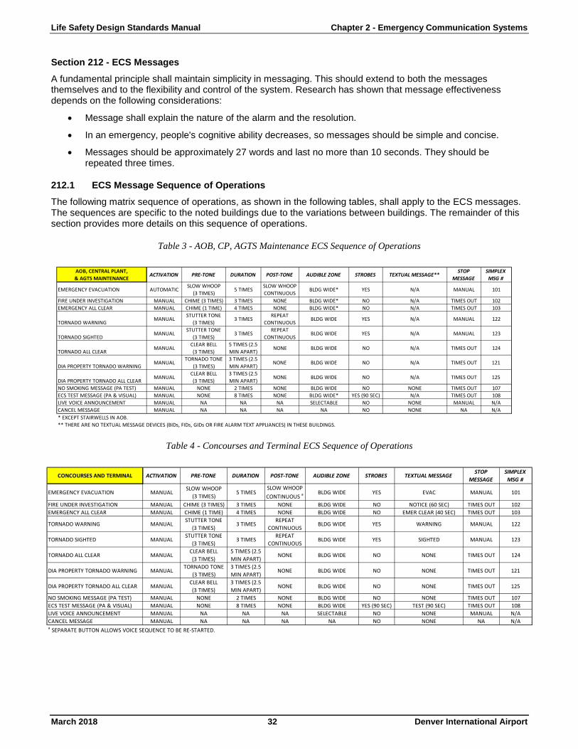
Life Safety Design Standards Manual Chapter 2 - Emergency Communication Systems
March 2018 32 Denver International Airport
Section 212 - ECS Messages A fundamental principle shall maintain simplicity in messaging. This should extend to both the messages themselves and to the flexibility and control of the system. Research has shown that message effectiveness depends on the following considerations:
• Message shall explain the nature of the alarm and the resolution.
• In an emergency, people's cognitive ability decreases, so messages should be simple and concise.
• Messages should be approximately 27 words and last no more than 10 seconds. They should be repeated three times.
212.1 ECS Message Sequence of Operations The following matrix sequence of operations, as shown in the following tables, shall apply to the ECS messages. The sequences are specific to the noted buildings due to the variations between buildings. The remainder of this section provides more details on this sequence of operations.
Table 3 - AOB, CP, AGTS Maintenance ECS Sequence of Operations
Table 4 - Concourses and Terminal ECS Sequence of Operations
EMERGENCY EVACUATION AUTOMATICSLOW WHOOP
(3 TIMES)5 TIMES
SLOW WHOOP CONTINUOUS
BLDG WIDE* YES N/A MANUAL 101
FIRE UNDER INVESTIGATION MANUAL CHIME (3 TIMES) 3 TIMES NONE BLDG WIDE* NO N/A TIMES OUT 102EMERGENCY ALL CLEAR MANUAL CHIME (1 TIME) 4 TIMES NONE BLDG WIDE* NO N/A TIMES OUT 103
TORNADO WARNINGMANUAL
STUTTER TONE(3 TIMES)
3 TIMESREPEAT
CONTINUOUSBLDG WIDE YES N/A MANUAL 122
TORNADO SIGHTEDMANUAL
STUTTER TONE(3 TIMES)
3 TIMESREPEAT
CONTINUOUSBLDG WIDE YES N/A MANUAL 123
TORNADO ALL CLEARMANUAL
CLEAR BELL(3 TIMES)
5 TIMES (2.5 MIN APART)
NONE BLDG WIDE NO N/A TIMES OUT 124
DIA PROPERTY TORNADO WARNINGMANUAL
TORNADO TONE(3 TIMES)
3 TIMES (2.5 MIN APART)
NONE BLDG WIDE NO N/A TIMES OUT 121
DIA PROPERTY TORNADO ALL CLEARMANUAL
CLEAR BELL(3 TIMES)
3 TIMES (2.5 MIN APART)
NONE BLDG WIDE NO N/A TIMES OUT 125
NO SMOKING MESSAGE (PA TEST) MANUAL NONE 2 TIMES NONE BLDG WIDE NO NONE TIMES OUT 107ECS TEST MESSAGE (PA & VISUAL) MANUAL NONE 8 TIMES NONE BLDG WIDE* YES (90 SEC) N/A TIMES OUT 108LIVE VOICE ANNOUNCEMENT MANUAL NA NA NA SELECTABLE NO NONE MANUAL N/ACANCEL MESSAGE MANUAL NA NA NA NA NO NONE NA N/A* EXCEPT STAIRWELLS IN AOB.** THERE ARE NO TEXTUAL MESSAGE DEVICES (BIDs, FIDs, GIDs OR FIRE ALARM TEXT APPLIANCES) IN THESE BUILDINGS.
SIMPLEX MSG #
STROBES TEXTUAL MESSAGE**STOP
MESSAGEPRE-TONE
AOB, CENTRAL PLANT,& AGTS MAINTENANCE
ACTIVATION DURATION AUDIBLE ZONEPOST-TONE
EMERGENCY EVACUATION MANUALSLOW WHOOP
(3 TIMES)5 TIMES
SLOW WHOOP CONTINUOUS a BLDG WIDE YES EVAC MANUAL 101
FIRE UNDER INVESTIGATION MANUAL CHIME (3 TIMES) 3 TIMES NONE BLDG WIDE NO NOTICE (60 SEC) TIMES OUT 102EMERGENCY ALL CLEAR MANUAL CHIME (1 TIME) 4 TIMES NONE BLDG WIDE NO EMER CLEAR (40 SEC) TIMES OUT 103
TORNADO WARNING MANUALSTUTTER TONE
(3 TIMES)3 TIMES
REPEATCONTINUOUS
BLDG WIDE YES WARNING MANUAL 122
TORNADO SIGHTED MANUALSTUTTER TONE
(3 TIMES)3 TIMES
REPEATCONTINUOUS
BLDG WIDE YES SIGHTED MANUAL 123
TORNADO ALL CLEAR MANUALCLEAR BELL(3 TIMES)
5 TIMES (2.5 MIN APART)
NONE BLDG WIDE NO NONE TIMES OUT 124
DIA PROPERTY TORNADO WARNING MANUALTORNADO TONE
(3 TIMES)3 TIMES (2.5 MIN APART)
NONE BLDG WIDE NO NONE TIMES OUT 121
DIA PROPERTY TORNADO ALL CLEAR MANUALCLEAR BELL(3 TIMES)
3 TIMES (2.5 MIN APART)
NONE BLDG WIDE NO NONE TIMES OUT 125
NO SMOKING MESSAGE (PA TEST) MANUAL NONE 2 TIMES NONE BLDG WIDE NO NONE TIMES OUT 107ECS TEST MESSAGE (PA & VISUAL) MANUAL NONE 8 TIMES NONE BLDG WIDE YES (90 SEC) TEST (90 SEC) TIMES OUT 108LIVE VOICE ANNOUNCEMENT MANUAL NA NA NA SELECTABLE NO NONE MANUAL N/ACANCEL MESSAGE MANUAL NA NA NA NA NO NONE NA N/Aa SEPARATE BUTTON ALLOWS VOICE SEQUENCE TO BE RE-STARTED.
SIMPLEX MSG #
ACTIVATION DURATION AUDIBLE ZONE STROBES TEXTUAL MESSAGESTOP
MESSAGECONCOURSES AND TERMINAL PRE-TONE POST-TONE
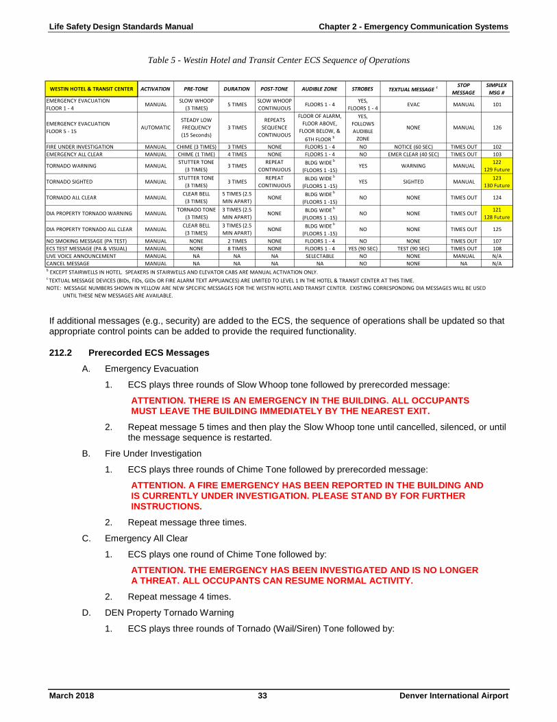
Life Safety Design Standards Manual Chapter 2 - Emergency Communication Systems
March 2018 33 Denver International Airport
Table 5 - Westin Hotel and Transit Center ECS Sequence of Operations
If additional messages (e.g., security) are added to the ECS, the sequence of operations shall be updated so that appropriate control points can be added to provide the required functionality.
212.2 Prerecorded ECS Messages A. Emergency Evacuation
1. ECS plays three rounds of Slow Whoop tone followed by prerecorded message:
ATTENTION. THERE IS AN EMERGENCY IN THE BUILDING. ALL OCCUPANTS MUST LEAVE THE BUILDING IMMEDIATELY BY THE NEAREST EXIT.
2. Repeat message 5 times and then play the Slow Whoop tone until cancelled, silenced, or until the message sequence is restarted.
B. Fire Under Investigation
1. ECS plays three rounds of Chime Tone followed by prerecorded message:
ATTENTION. A FIRE EMERGENCY HAS BEEN REPORTED IN THE BUILDING AND IS CURRENTLY UNDER INVESTIGATION. PLEASE STAND BY FOR FURTHER INSTRUCTIONS.
2. Repeat message three times.
C. Emergency All Clear
1. ECS plays one round of Chime Tone followed by:
ATTENTION. THE EMERGENCY HAS BEEN INVESTIGATED AND IS NO LONGER A THREAT. ALL OCCUPANTS CAN RESUME NORMAL ACTIVITY.
2. Repeat message 4 times.
D. DEN Property Tornado Warning
1. ECS plays three rounds of Tornado (Wail/Siren) Tone followed by:
EMERGENCY EVACUATIONFLOOR 1 - 4
MANUALSLOW WHOOP
(3 TIMES)5 TIMES
SLOW WHOOP CONTINUOUS
FLOORS 1 - 4YES,
FLOORS 1 - 4EVAC MANUAL 101
EMERGENCY EVACUATIONFLOOR 5 - 15
AUTOMATICSTEADY LOW FREQUENCY(15 Seconds)
3 TIMESREPEATS
SEQUENCE CONTINUOUS
FLOOR OF ALARM, FLOOR ABOVE,
FLOOR BELOW, & 6TH FLOOR b
YES,FOLLOWS AUDIBLE
ZONE
NONE MANUAL 126
FIRE UNDER INVESTIGATION MANUAL CHIME (3 TIMES) 3 TIMES NONE FLOORS 1 - 4 NO NOTICE (60 SEC) TIMES OUT 102EMERGENCY ALL CLEAR MANUAL CHIME (1 TIME) 4 TIMES NONE FLOORS 1 - 4 NO EMER CLEAR (40 SEC) TIMES OUT 103
TORNADO WARNING MANUALSTUTTER TONE
(3 TIMES)3 TIMES
REPEATCONTINUOUS
BLDG WIDE b
(FLOORS 1 -15)YES WARNING MANUAL
122129 Future
TORNADO SIGHTED MANUALSTUTTER TONE
(3 TIMES)3 TIMES
REPEATCONTINUOUS
BLDG WIDE b
(FLOORS 1 -15)YES SIGHTED MANUAL
123130 Future
TORNADO ALL CLEAR MANUALCLEAR BELL(3 TIMES)
5 TIMES (2.5 MIN APART)
NONE BLDG WIDE b
(FLOORS 1 -15)NO NONE TIMES OUT 124
DIA PROPERTY TORNADO WARNING MANUALTORNADO TONE
(3 TIMES)3 TIMES (2.5 MIN APART)
NONE BLDG WIDE b
(FLOORS 1 -15)NO NONE TIMES OUT
121128 Future
DIA PROPERTY TORNADO ALL CLEAR MANUALCLEAR BELL(3 TIMES)
3 TIMES (2.5 MIN APART)
NONE BLDG WIDE b
(FLOORS 1 -15)NO NONE TIMES OUT 125
NO SMOKING MESSAGE (PA TEST) MANUAL NONE 2 TIMES NONE FLOORS 1 - 4 NO NONE TIMES OUT 107ECS TEST MESSAGE (PA & VISUAL) MANUAL NONE 8 TIMES NONE FLOORS 1 - 4 YES (90 SEC) TEST (90 SEC) TIMES OUT 108LIVE VOICE ANNOUNCEMENT MANUAL NA NA NA SELECTABLE NO NONE MANUAL N/ACANCEL MESSAGE MANUAL NA NA NA NA NO NONE NA N/Ab EXCEPT STAIRWELLS IN HOTEL. SPEAKERS IN STAIRWELLS AND ELEVATOR CABS ARE MANUAL ACTIVATION ONLY.c TEXTUAL MESSAGE DEVICES (BIDs, FIDs, GIDs OR FIRE ALARM TEXT APPLIANCES) ARE LIMITED TO LEVEL 1 IN THE HOTEL & TRANSIT CENTER AT THIS TIME.NOTE: MESSAGE NUMBERS SHOWN IN YELLOW ARE NEW SPECIFIC MESSAGES FOR THE WESTIN HOTEL AND TRANSIT CENTER. EXISTING CORRESPONDING DIA MESSAGES WILL BE USED
UNTIL THESE NEW MESSAGES ARE AVAILABLE.
WESTIN HOTEL & TRANSIT CENTER ACTIVATION PRE-TONE DURATION POST-TONESIMPLEX MSG #
AUDIBLE ZONE STROBES TEXTUAL MESSAGE c STOP MESSAGE

Life Safety Design Standards Manual Chapter 2 - Emergency Communication Systems
March 2018 34 Denver International Airport
ATTENTION PLEASE. THE NATIONAL WEATHER SERVICE HAS ISSUED A TORNADO WARNING THAT INCLUDES DENVER INTERNATIONAL AIRPORT. PLEASE REMAIN ALERT FOR ANY INSTRUCTIONS.
2. Repeat message three times, once every 2.5 minutes.
E. DEN Property Tornado All Clear
1. ECS plays three rounds of Clear Bell Tone followed by:
ATTENTION PLEASE. THE THREAT OF A TORNADO IS NO LONGER PRESENT. YOU MAY NOW RESUME NORMAL OPERATIONS. REMAIN ALERT FOR CHANGING WEATHER CONDITIONS.
2. Repeat message three times, once every 2.5 minutes.
F. Tornado Warning
1. ECS plays three rounds of Stutter (Warble) Tone followed by:
ATTENTION PLEASE. THE NATIONAL WEATHER SERVICE HAS ISSUED A TORNADO WARNING THAT INCLUDES DENVER INTERNATIONAL AIRPORT CONCOURSES AND TERMINAL. TAKE SHELTER IMMEDIATELY IN MARKED STAIRWELLS AND RESTROOMS. STAY AWAY FROM WINDOWS AND BE ALERT FOR FURTHER INSTRUCTIONS.
2. Repeat message three times. Approximately 30 second pause between sequences and repeats continuously until cancelled or silenced.
G. Tornado Sighted
1. ECS plays three rounds of Stutter (Warble) Tone followed by:
ATTENTION PLEASE. A TORNADO HAS BEEN SIGHTED AT THE AIRPORT. TAKE SHELTER IMMEDIATELY IN MARKED STAIRWELLS AND RESTROOMS. STAY AWAY FROM WINDOWS AND BE ALERT FOR FURTHER INSTRUCTIONS.
2. Repeat message three times. Approximately 40 second pause between sequences and repeats continuously until cancelled or silenced.
H. Tornado All Clear
1. ECS plays three rounds of Clear Bell tone followed by:
THE THREAT OF A TORNADO IS NO LONGER PRESENT. YOU MAY LEAVE YOUR SHELTER. REMAIN ALERT FOR CHANGING WEATHER CONDITIONS.
2. Repeat message five times, approximately once every 2.5 minutes.
I. No Smoking Message (PA Test)
1. ECS Plays:
ATTENTION. SMOKING IS PERMITTED IN DESIGNATED AREAS ONLY. THESE AREAS ARE CLEARLY MARKED FOR YOUR CONVENIENCE. ALL SMOKING MATERIALS MUST BE EXTINGUISHED IN PROPER RECEPTACLES BEFORE LEAVING SMOKING AREAS. THANK YOU.
2. Repeat two times.
J. ECS Test Message (PA and Visual Test)
1. ECS Plays:
ATTENTION. THIS IS A TEST OF THE EMERGENCY COMMUNICATION SYSTEM. THIS IS ONLY A TEST. THANK YOU.
2. Repeat 8 times.
K. Westin Hotel Emergency Evacuation
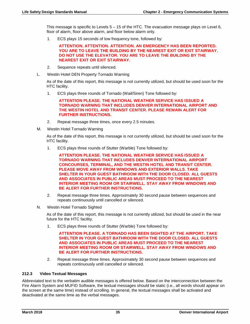
Life Safety Design Standards Manual Chapter 2 - Emergency Communication Systems
March 2018 35 Denver International Airport
This message is specific to Levels 5 – 15 of the HTC. The evacuation message plays on Level 6, floor of alarm, floor above alarm, and floor below alarm only.
1. ECS plays 15 seconds of low frequency tone, followed by:
ATTENTION. ATTENTION. ATTENTION. AN EMERGENCY HAS BEEN REPORTED. YOU ARE TO LEAVE THE BUILDING BY THE NEAREST EXIT OR EXIT STAIRWAY. DO NOT USE THE ELEVATOR. YOU ARE TO LEAVE THE BUILDING BY THE NEAREST EXIT OR EXIT STAIRWAY.
2. Sequence repeats until silenced.
L. Westin Hotel DEN Property Tornado Warning
As of the date of this report, this message is not currently utilized, but should be used soon for the HTC facility.
1. ECS plays three rounds of Tornado (Wail/Siren) Tone followed by:
ATTENTION PLEASE. THE NATIONAL WEATHER SERVICE HAS ISSUED A TORNADO WARNING THAT INCLUDES DENVER INTERNATIONAL AIRPORT AND THE WESTIN HOTEL AND TRANSIT CENTER. PLEASE REMAIN ALERT FOR FURTHER INSTRUCTIONS.
2. Repeat message three times, once every 2.5 minutes.
M. Westin Hotel Tornado Warning
As of the date of this report, this message is not currently utilized, but should be used soon for the HTC facility.
1. ECS plays three rounds of Stutter (Warble) Tone followed by:
ATTENTION PLEASE. THE NATIONAL WEATHER SERVICE HAS ISSUED A TORNADO WARNING THAT INCLUDES DENVER INTERNATIONAL AIRPORT CONCOURSES, TERMINAL, AND THE WESTIN HOTEL AND TRANSIT CENTER. PLEASE MOVE AWAY FROM WINDOWS AND EXTERIOR WALLS. TAKE SHELTER IN YOUR GUEST BATHROOM WITH THE DOOR CLOSED. ALL GUESTS AND ASSOCIATES IN PUBLIC AREAS MUST PROCEED TO THE NEAREST INTERIOR MEETING ROOM OR STAIRWELL. STAY AWAY FROM WINDOWS AND BE ALERT FOR FURTHER INSTRUCTIONS.
2. Repeat message three times. Approximately 30 second pause between sequences and repeats continuously until cancelled or silenced.
N. Westin Hotel Tornado Sighted
As of the date of this report, this message is not currently utilized, but should be used in the near future for the HTC facility.
1. ECS plays three rounds of Stutter (Warble) Tone followed by:
ATTENTION PLEASE. A TORNADO HAS BEEN SIGHTED AT THE AIRPORT. TAKE SHELTER IN YOUR GUEST BATHROOM WITH THE DOOR CLOSED. ALL GUESTS AND ASSOCIATES IN PUBLIC AREAS MUST PROCEED TO THE NEAREST INTERIOR MEETING ROOM OR STAIRWELL. STAY AWAY FROM WINDOWS AND BE ALERT FOR FURTHER INSTRUCTIONS.
2. Repeat message three times. Approximately 30 second pause between sequences and repeats continuously until cancelled or silenced.
212.3 Video Textual Messages Abbreviated text to the verbatim audible messages is offered below. Based on the interconnection between the Fire Alarm System and MUFID Software, the textual messages should be static (i.e., all words should appear on the screen at the same time) instead of scrolling. In general, the textual messages shall be activated and deactivated at the same time as the verbal messages.

Life Safety Design Standards Manual Chapter 2 - Emergency Communication Systems
March 2018 36 Denver International Airport
A. Emergency Evacuation (Evac)
B. Fire Under Investigation (Notice)
C. Emergency All Clear (All Clear)
D. Tornado Warning (Warning)
E. Tornado Sighted (Sighted)
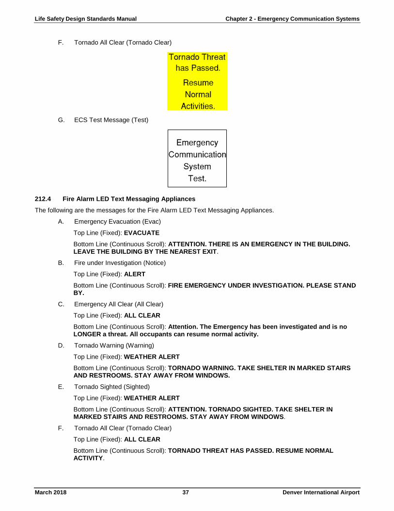
Life Safety Design Standards Manual Chapter 2 - Emergency Communication Systems
March 2018 37 Denver International Airport
F. Tornado All Clear (Tornado Clear)
G. ECS Test Message (Test)
212.4 Fire Alarm LED Text Messaging Appliances The following are the messages for the Fire Alarm LED Text Messaging Appliances.
A. Emergency Evacuation (Evac)
Top Line (Fixed): EVACUATE
Bottom Line (Continuous Scroll): ATTENTION. THERE IS AN EMERGENCY IN THE BUILDING. LEAVE THE BUILDING BY THE NEAREST EXIT.
B. Fire under Investigation (Notice)
Top Line (Fixed): ALERT
Bottom Line (Continuous Scroll): FIRE EMERGENCY UNDER INVESTIGATION. PLEASE STAND BY.
C. Emergency All Clear (All Clear)
Top Line (Fixed): ALL CLEAR
Bottom Line (Continuous Scroll): Attention. The Emergency has been investigated and is no LONGER a threat. All occupants can resume normal activity.
D. Tornado Warning (Warning)
Top Line (Fixed): WEATHER ALERT
Bottom Line (Continuous Scroll): TORNADO WARNING. TAKE SHELTER IN MARKED STAIRS AND RESTROOMS. STAY AWAY FROM WINDOWS.
E. Tornado Sighted (Sighted)
Top Line (Fixed): WEATHER ALERT
Bottom Line (Continuous Scroll): ATTENTION. TORNADO SIGHTED. TAKE SHELTER IN MARKED STAIRS AND RESTROOMS. STAY AWAY FROM WINDOWS.
F. Tornado All Clear (Tornado Clear)
Top Line (Fixed): ALL CLEAR
Bottom Line (Continuous Scroll): TORNADO THREAT HAS PASSED. RESUME NORMAL ACTIVITY.

Life Safety Design Standards Manual Chapter 2 - Emergency Communication Systems
March 2018 38 Denver International Airport
G. ECS Test Message (Test)
Top Line (Fixed): TEST
Bottom Line (Continuous Scroll): ATTENTION. THIS IS A TEST OF THE EMERGENCY COMMUNICATION SYSTEM.
Section 213 - ECS Screens A fundamental recommendation should maintain simplicity in the interface screens. This simplicity should extend to both the number of possible screens and to the simplicity and ease of use of each screen. Control of the screen is recommended to be via touch screen, but mouse control is acceptable. TSWs shall utilize a dedicated ECS Control Screen.
213.1 TSW Prerecorded Message Screen The TSW has a single ECS Control Screen, which contains selection buttons for all the various messages. Refer to Figure 8 - TSW ECS Control Screen. The screen is separated into six main sections:
1. Master Control Buttons to enable and cancel/disable the screen.
2. Help / Legend section to explain colors and operation.
3. Play Emergency Messages section to activate emergency messages for each of the buildings.
4. Play Test Messages section to activate test message for each of the buildings.
5. Play Tornado Messages to activate tornado-related messages site wide (not including the HTC).
6. Hotel and PTC section to activate tornado-related messages within the HTC.
Selection buttons are toggle-type buttons with a feedback color change indicating a change of state if the button has been selected. Travel/navigation, cancel/reset, and similar buttons shall not require change of state indications but shall simply perform the intended operation.
Figure 8 - TSW ECS Control Screen
To activate the ECS Control Screen, an Enable Button shall act as a confirming prompt message (e.g., Are You Sure? message). This enable button shall provide a final reminder to the authorized user that they are about to initiate the selected message. Cancel message, clear all, and navigate screen buttons shall not include a confirmation pop-up message.
The Restart Voice Message button is provided to allow an authorized user to re-initiate the emergency evacuation prerecorded message. This button shall not be active unless/until the Emergency Evacuation button (or equivalent) has been previously activated and the Evac message is still playing. This button shall immediately activate the Evac message to play 5 times, followed by Slow Whoop signal until cancelled or silenced. This button shall not include a confirming prompt message since the Evac signals are already active.

Life Safety Design Standards Manual Chapter 2 - Emergency Communication Systems
March 2018 39 Denver International Airport
213.2 ECS System Live Voice Selection Live voice announcements shall continue to be made from the IED Microphone Station and IED Touch Screen. This screen is also called the A-Panel. Refer to Figure 9 - IED Paging Panel (A Panel) and Digital Microphone Station. The operator shall select the area (zone) and key the microphone to conduct an announcement.
As an operational recommendation, it is recommended that live voice messages be made on a building wide basis due to the transient nature of the occupants. Selective zone paging should only be done when there is a specific reason to do so to avoid occupant confusion.
Figure 9 - IED Paging Panel (A Panel) and Digital Microphone Station
213.3 ECS/Fire Alarm Interface As a rule, the Simplex Fire Alarm System shall provide the prerecorded messages as detailed in this operational plan and the IED System shall provide the live voice capability, except as noted herein. The Simplex Fire Alarm System shall provide a dry contact to notify the ECS to accept the audio messages. The ECS shall accept the audio messages as well as providing live voice override.
For other required operations, the Simplex Fire Alarm System and PA/ECS and MUFID systems shall be interconnected via dry contacts. This interface, for both audio and video capture, is housed in the ECS/Fire Alarm Interface Panel (FA/ECS) located in the PA Communications Room in the North Terminal, Concourse A, Concourse B, and Concourse C and in the MDF room of the HTC. Contacts shall be maintained (i.e., latching), unless otherwise noted, so that visual displays are directly controlled by the Fire Alarm System to the extent possible. The dry contact shall remain latched for the duration of the playing message as detailed in Table 3 - AOB, CP, AGTS Maintenance ECS Sequence of Operations. An All Clear message shall deactivate its associated message latched contacts. ECS messages shall be allowed to override fire alarm messages. Simplex custom control programming shall be used to activate and latch (or deactivate) dry contacts.
Figure 10 - Fire Alarm/ECS Interface Cabinet

Life Safety Design Standards Manual Chapter 2 - Emergency Communication Systems
March 2018 40 Denver International Airport
Section 214 - ECS Maintenance As a critical life safety component of airport operations, it is critical that the ECS is properly monitored, inspected, and maintained. This can be done by proper adherence to applicable codes and standards.
214.1 System Addition or Alteration All system alterations or additions shall be done with the knowledge and assistance of DEN Life Safety and through a properly permitted process. Per the 2016 Denver Amendments to the 2015 IFC, construction permits are required for any work to Fire Alarm and Detection Systems, Emergency Alarm Systems, ECS, Mass Notification Systems, Public Safety Radio Communication Systems (RES), and Two-Way Communication Systems. Permits are required prior to the installation or modification of fire alarm and detection system and related equipment. Work performed to keep equipment operable or to make repairs is considered maintenance and, when performed in accordance with Denver Code and Fire Department policy, is not considered modification and shall not require a construction permit.
The 2016 Denver Amendments contains Appendix S (Construction of Airport Buildings and Structures) which states the following as applicable to the ECS:
Therefore, modifications/alterations or additions to the existing implemented DEN ECS require adherence to the above requirement. Tenant finishes and additions shall account for the prescriptive design of primary visual notification (i.e., strobes) per NFPA 72 as well as the capture and/or shunt of noted video displays. Given the unsupervised nature of the interface to non-DEN owned displays and the expense of the interface, if prescriptive visual notification is provided, shunting of video displays is the preferred method of integration with video displays exceeding 60” in size.
Addition of advertising displays in public areas of the airport complex shall be subject to the above stated Denver Amendments as well. Given the unsupervised nature of the interface to non-MUFID, non-DEN owned advertising displays and the expense of the interface, shunting of video displays is the preferred method of integration with video displays exceeding 60” in size. The exception to this would be if there is a lack of prescriptive (i.e., strobes) and/or supplementary (i.e., MUFID displays) visual notification in the area, in which an engineering decision should be made on whether to capture the advertising display.
Should modifications or additions be required in utility or baggage tunnels, the following item from the 2016 Denver Amendments, Appendix S, shall apply:
System modifications and additions should be designed in accordance to applicable code and the DEN Design Standards Manual. This includes detailed Design Documents that provides prescriptive visual notification coverage, audibility, and intelligibility of loudspeakers, and coordinated capture or shunting of video displays.
It is critical to maintain accurate record as-built drawings of all system components. As the system is expanded and modified, documentation should be provided to back to DEN Life Safety. This includes the layout of individual loudspeakers, loudspeaker zoning, screen capture, screen shunt, and related items. As systems are altered, DEN has implemented a NFPA 72 Record of Completion form that can be updated to reflect additions to the ECS and/or Fire Alarm system. This form should be utilized each time additional equipment is provided for the system.
Life Safety Design Standards Manual Chapter 2 - Emergency Communication Systems
March 2018 41 Denver International Airport
214.2 Inspection and Maintenance On-going system inspection and maintenance shall be performed by or under the direction of DEN Life Safety. The inspection, testing, and maintenance of fire alarm and ECS shall be performed in accordance with NFPA 72 Chapter 14. In general, this requires a semi-annual visual inspection of the control equipment and an annual visual inspection of all other equipment. It also requires annual testing of all components of the fire alarm and ECS.
Failures of any primary component of said systems shall be documented and repaired in accordance with applicable code. Failures of supplementary components of said systems, including capture of individual video displays, should be documented and repaired in a timely manner. This is with the acknowledgement of the fact that an individual video display failure shall not adversely affect the overall performance of the ECS
END OF CHAPTER

This Page Intentionally Blank

Life Safety Design Standards Manual Chapter 3 - Fire Alarm Systems
March 2018 43 Denver International Airport
Chapter 3 - Fire Alarm Systems
Section 300 - Fire Detection and Alarm System
Section 301 - Scope This chapter provides guidance to the Design Consultant in the area of Fire Detection and Alarm System design for DEN. General criteria are set forth as well as drawing and design analysis requirements.
Section 302 - System Description The Fire Alarm System installed in the main DEN complex is a Network Simplex Fire Alarm System as supported by SimplexGrinnell, LLP. The system consists of a 50-Node Network, connected via a Class A fiber optic backbone. Most nodes are 4100ES fire alarm control units with an integrated and supervised system of initiating and control devices and notification appliances. There are twelve (12) network head-end annunciation units, known as TSW, located throughout the facility in Fire Command Centers and DEN Operation Centers.
The Simplex Fire Alarm System was progressively installed from 2010 through 2017. The system was integrated with the airports IED paging/PA system in 2014-15 to form an integrated ECS.
Section 303 - Criteria Fire Detection and Alarm Systems are required to meet City and County of Denver requirements. Fire Detection and Alarm Systems shall be provided in accordance with the latest editions of the standards and codes listed in the Standards and Criteria DSM, as well as the IBC and IFC as currently adopted and amended by the City and County of Denver. Note that in the 2016 Denver Amendments to IBC, Appendix S has specific requirements for airports, which are in addition to all other referenced standards.
Section 304 - Drawing Requirements The Design Consultant shall show all Fire Detection and Alarm System requirements in the Contract Documents. Single-line diagrams shall be provided with the construction documents. At this stage, wiring information need not be presented. Wiring information shall be provided during the shop drawing process. As a minimum, the drawings shall show the following:
• A single-line diagram depicting all control panels; initiating devices; indicating devices; heating,ventilation, and air conditioning (HVAC) interface functions; protection system activation devices; powerconnections; and central alarm system communication interfaces, as well as the control panel to whicheach device or group of devices is connected.
Capacities and available addresses must be verified during the shop drawing process.
• Appropriate contacts to provide the required interlocks with the Fire Alarm System.
• Control schematic diagrams for air handling equipment shall be provided by the Mechanical Engineer.
• Provide accurate floor plans showing the location of all control panels and devices.
The following shall be provided with the Design Development Review Document:
• Preliminary floor plan.
• Fire detection and alarm system features may be combined on common floor plans with the lightingdesign for the facility.
• Control panel locations should be shown as well as device layout for each functional type of space inthe facility. Room and door numbers must be shown on floor plans as required by the BuildingInformation Model (BIM). Refer to the BIM DSM.
All Design Documents shall be signed and sealed by a Professional Engineer licensed in the State of Colorado.
DEN Master Diagrams are available upon request from the DEN Electrical Engineer. Master diagrams shall be updated and returned to the DEN Electrical Engineer at IFC and Record Document phases.
Permit ready fire alarm drawings to be provided at the Issue for Construction submittal. Deferred submittals shall not be allowed.

Life Safety Design Standards Manual Chapter 3 - Fire Alarm Systems
March 2018 44 Denver International Airport
Section 305 - Design Analysis Requirements The Design Consultant shall provide a Fire Alarm System Basis of Design to substantiate the Fire Detection and Alarm System design. The Fire Alarm System Basis of Design shall have at least the following categories included:
• Building description
• Laws and regulations
• Design responsibilities
• Fire alarm system type
• Design methodology
• Testing and inspection
• Equipment and tools
• Requirements for submittals
• End of job closeout
Section 306 - More Stringent Document Provisions If there is a conflict among the requirements of this document and the NFPA documents referenced above, the Design Consultant shall comply with the more stringent requirements.
Section 307 - Initiating Devices
307.1 Addressable Heat Detectors Heat detection shall be provided as determined by the DAR. The Design Consultant shall make appropriate accommodations in accordance with NFPA 72 when applying heat detectors to de-rate for ceiling heights and consider unusual ceiling configurations.
307.2 Addressable Smoke Detectors Smoke detectors shall be provided as determined by the DAR. Smoke detectors shall be the addressable type and compatible with the Fire Alarm System. Conventional smoke detectors may be used in special conditions where addressable detectors are not compatible with the environmental or hazard condition present. Where required, combination smoke/heat detectors may be installed.
307.3 Addressable Manual Stations Manual stations shall be provided as determined by the DAR. Manual stations shall be double-action type devices with key operated reset and shall be addressable where permitted by ambient conditions. Where ambient conditions do not allow use of addressable stations, use non-addressable stations that are tied back to an I/O panel in a conditioned space where monitoring can take place.
307.4 Addressable Monitor Modules Provide addressable monitor modules to monitor non-addressable devices including the following:
A. Valve Tamper Switches
Provide monitor devices for non-addressable valve tamper switches. Supervise the valve position asdefined by the fire suppression system design (i.e., either open or closed position). Each valvetamper switch shall be individually monitored.
B. Water Flow Indicator
Provide monitor devices for non-addressable water flow indicators. Water flow indicators includepaddle-type flow switches, pressure switches, and other types. Ensure sequence of operations

Life Safety Design Standards Manual Chapter 3 - Fire Alarm Systems
March 2018 45 Denver International Airport
associated with water flow indication is consistent with protected areas (e.g., initiation of smoke control zones, limited area notification, elevator shunt trip, etc.).
C. Alarm Pressure Switch
For all dry-pipe systems, pre-action, and deluge systems, monitor alarm pressure switch for individual system annunciation.
D. Low Air Monitoring
For all dry-pipe and pre-action systems, provide piping supervision by means of low air pressure switches. Low air pressure switches shall be monitored by the Fire Alarm System.
E. Other Fire System Alarm Monitoring
Fire system alarm devices not associated with sprinkler systems include, but are not limited to, gaseous fire extinguishing systems, dry and wet chemical systems (including kitchen hood systems), foam systems, and other fire suppression or extinguishing systems. Provide a means to monitor individually each non-addressable alarm devices.
307.5 Fire Pump Supervision In addition to the requirements in NFPA 20 for supervision, supervise power and pump run status from each fire pump and pressure maintenance (jockey) pump.
Section 308 - Notification Devices
308.1 Audible Alarms A. Terminal Complex (Jeppesen Terminal, Concourses, AOB, CUP, and HTC)
1. Audible alarm devices shall be used in all areas as required by applicable codes.
2. The audible signal shall be significantly different from other signals and shall be per the requirements of the DEN ECS Operational Plan. Refer to Section 207 - ECS Operational Plan for information about the plan.
3. The audible notification shall occur through the ECS.
4. All public spaces, including Tenant and Airline spaces, shall have audible coverage through the ECS. Tone notifications (i.e., fire alarm audible devices) may be provided in non-public areas with high ambient noise levels.
B. Out-Buildings
1. Audible alarm devices shall be used in all areas as required by applicable codes.
2. The audible signal shall be significantly different from other signals and shall be per the requirements of NFPA 72.
3. Audible notification shall occur through fire alarm horn appliances, unless otherwise required by applicable code.
308.2 Visual Alarms Strobes with ALERT shall be installed on walls or ceilings as indicated on the Fire Alarm System drawings. Refer to Figure 11- Typical ALERT Strobes. These appliances are installed throughout public and non-public areas in accordance with Administrative Modification numbers 6 and 7. All future installation (e.g., Tenant finishes, concourse expansions, remodels, etc.) of visual notification appliances shall be installed to the prescriptive requirements of NFPA 72.

Life Safety Design Standards Manual Chapter 3 - Fire Alarm Systems
March 2018 46 Denver International Airport
Figure 11- Typical ALERT Strobes
ALERT Strobes shall be activated anytime an emergency message requires an action to be taken by a building occupant. Currently this includes only the emergency evacuation message and weather/tornado relocation messages. ALERT Strobes shall not be activated during any message that shall not require an action to be taken by a building occupant. This specifically includes an all-clear message or any other type of non-emergency message. Once activated, these appliances shall be deactivated when the emergency message is deactivated/stopped.
In the AOB, CUP, Concourse A, AGTS Maintenance Facility, and in certain AGTS spaces between the AGTS tunnels, standard (non-addressable) visual notification appliances are utilized as manufactured by Eaton Cooper Notification (i.e., Wheelock). In the Terminal, Concourse B, Concourse C, and HTC, addressable visual notification appliances are utilized as manufactured by Simplex.
A. Terminal Complex (Jeppesen Terminal, Concourses, HTC) 1. Visual appliances shall be provided in all areas in accordance with NFPA 72.
2. Visual notification devices installed in public spaces, including Tenant spaces, shall be white with red letters that read, ALERT.
3. Visual notification devices installed in back-of-house spaces shall be red with white letters that read, ALERT.
4. Candela rating shall be included on the design drawings.
5. The DEN Electrical Engineer shall determine if devices are to be conventional or addressable.
B. Out-Buildings
1. Visual appliances shall be provided in all areas in accordance with NFPA 72.
2. Visual notification devices shall be red with white letters that read, FIRE.
3. Candela rating shall be included on the design drawings.
308.3 Audible/Visual Notification Combination Horn/Strobe appliances with ALERT shall be installed on walls or ceilings as indicated on the Fire Alarm System drawings. These appliances are installed in non-public areas like electrical and mechanical spaces that are not covered by ECS loudspeakers. The horns are programmed to deactivate (silence) at the same time as the strobes, although they shall be controllable separate from the strobes. All future installations (e.g., Tenant finishes, concourse expansions, remodels, etc.) should have visual-only notification appliances (i.e., strobes) installed with ECS loudspeaker coverage provided. Horn/Strobe appliances should not be necessary for future installations without a specific reason to do so.
ALERT Horn/Strobes shall be activated anytime an emergency message requires an action to be taken by a building occupant. Currently this includes only the emergency evacuation message and weather/tornado relocation messages. ALERT Horn/Strobes shall not be activated during any message that shall not require an action to be taken by a building occupant. This specifically includes an all-clear message or any other type of non-
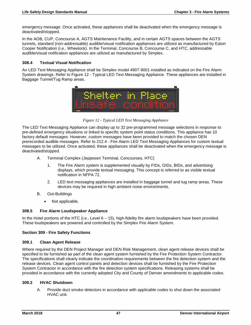
Life Safety Design Standards Manual Chapter 3 - Fire Alarm Systems
March 2018 47 Denver International Airport
emergency message. Once activated, these appliances shall be deactivated when the emergency message is deactivated/stopped.
In the AOB, CUP, Concourse A, AGTS Maintenance Facility, and in certain AGTS spaces between the AGTS tunnels, standard (non-addressable) audible/visual notification appliances are utilized as manufactured by Eaton Cooper Notification (i.e., Wheelock). In the Terminal, Concourse B, Concourse C, and HTC, addressable audible/visual notification appliances are utilized as manufactured by Simplex.
308.4 Textual Visual Notification An LED Text Messaging Appliance shall be Simplex model 4907-9001 installed as indicated on the Fire Alarm System drawings. Refer to Figure 12 - Typical LED Text Messaging Appliance. These appliances are installed in Baggage Tunnel/Tug Ramp areas.
Figure 12 - Typical LED Text Messaging Appliance
The LED Text Messaging Appliance can display up to 32 pre-programmed message selections in response to pre-defined emergency situations or linked to specific system point status conditions. This appliance has 10 factory default messages. However, custom messages have been provided to match the chosen DEN prerecorded audible messages. Refer to 212.4 - Fire Alarm LED Text Messaging Appliances for custom textual messages to be utilized. Once activated, these appliances shall be deactivated when the emergency message is deactivated/stopped.
A. Terminal Complex (Jeppesen Terminal, Concourses, HTC) 1. The Fire Alarm system is supplemented visually by FIDs, GIDs, BIDs, and advertising
displays, which provide textual messaging. This concept is referred to as visible textual notification in NFPA 72.
2. LED text messaging appliances are installed in baggage tunnel and tug ramp areas. These devices may be required in high ambient noise environments.
B. Out-Buildings
• Not applicable.
308.5 Fire Alarm Loudspeaker Appliance In the Hotel portions of the HTC (i.e., Level 6 – 15), high-fidelity fire alarm loudspeakers have been provided. These loudspeakers are powered and controlled by the Simplex Fire Alarm System.
Section 309 - Fire Safety Functions
309.1 Clean Agent Release Where required by the DEN Project Manager and DEN Risk Management, clean agent release devices shall be specified to be furnished as part of the clean agent system furnished by the Fire Protection System Contractor. The specifications shall clearly indicate the coordination requirements between the fire detection system and the release devices. Clean agent control panels and detection devices shall be furnished by the Fire Protection System Contractor in accordance with the fire detection system specifications. Releasing systems shall be provided in accordance with the currently adopted City and County of Denver amendments to applicable codes.
309.2 HVAC Shutdown A. Provide duct smoke detectors in accordance with applicable codes to shut down the associated
HVAC unit.

Life Safety Design Standards Manual Chapter 3 - Fire Alarm Systems
March 2018 48 Denver International Airport
B. The duct smoke detectors shall initiate a supervisory condition on the Fire Alarm System.
C. Where installed, combination fire/smoke dampers shall be individually controlled by the Fire Alarm System.
D. HVAC unit shutdown and damper control shall be achieved by addressable fire alarm relays.
309.3 Door Release A. Fire alarm system shall interrupt power to magnetic door holders to close the doors and establish
release for required controlled exit doors.
B. Doors shall be released consistent with the smoke control zones and security door release sequences may be considered Security Sensitive Information (SSI).
C. Door release shall be achieved by addressable fire alarm relays.
309.4 Elevator Recall Where elevators are installed, modified, or replaced, the Fire Alarm System shall provide elevator recall and shunt trip functions as applicable, per NFPA 72. Elevator interfaces shall be achieved by addressable fire alarm relays.
309.5 Media Shunt In Tenants with private audio/visual systems or other visual advertising, media shunt shall be provided during emergency messaging activation. Media shunt shall be achieved by addressable fire alarm relays.
Section 310 - System Configuration
310.1 Circuit Supervision Circuit supervision shall be provided consistent with NFPA 72.
310.2 Circuit Survivability To provide a higher level of survivability from fire and physical damage, a level of protection consistent with Level 1 pathway survivability per NFPA 72 shall be provided for the audible ECS pathways between the ECS controls to the loudspeakers and for visual notification circuits to fire alarm visual appliances (strobes).
310.3 Power Supply The FACPs shall be designed to operate from 120 volt, 60-hertz, single-phase power source. In buildings equipped with an emergency power source, connect FACPs to the emergency source. The FACPs shall be provided with battery backup of sufficient capacity to allow system monitoring for a period as required by NFPA 72 and then with enough reserve capacity to actuate local alarms for fifteen minutes. Provide UPS power with a minimum runtime of 4 hours for all graphic workstations.
310.4 Graphic Annunciation A. Terminal Complex (Jeppesen Terminal, Concourses, HTC)
Graphic annunciation shall be provided at all of the Fire Command Centers via the TSW that shall indicate the location of the actuated detection or protection device. All additions or modifications to the system, including floor plan changes, shall be incorporated into the workstation graphics.
B. Out-Buildings
Graphic annunciation panels shall be provided in accordance with currently adopted City and County of Denver fire code amendments. The panel shall be located in the main entrance at an AHJ approved location.
310.5 System Configuration A. Terminal Complex (Jeppesen Terminal, Concourses, HTC)

Life Safety Design Standards Manual Chapter 3 - Fire Alarm Systems
March 2018 49 Denver International Airport
The system is a single network for all fire alarm panels. The primary control components are the FACP that operates in a peer-to-peer node configuration and are distributed throughout the complex. The SimplexGrinnell computer based graphic display panels (i.e., TSW) are individual nodes on the network.
Figure 13- Terminal Complex
Major expansions may require the addition of new nodes, with consultation between the DEN Electrical Engineer and SimplexGrinnell.
B. Out-Buildings
In general, all outbuildings are standalone Fire Alarm Systems with approved central station monitoring.
310.6 Network Communications A. Terminal Complex (Jeppesen Terminal, Concourses, HTC)
The Fire Alarm System for the Terminal Complex is a proprietary network that interlinks the Fire Command Centers, including the graphic workstations provided in each Fire Command Center. The fire alarm panels shall be part of this network and shall be capable of communicating through the network for both alarm reporting and command and control functions. Network communications shall be via Class-A fiber-optic or copper wiring in accordance with NFPA 72.
DEN Fire Alarm System shall be monitored directly by Denver Fire Department (DFD) Dispatch through an AES Corporation wireless transceiver interface. An AES transceiver is provided within each primary building.
Fire Alarm network diagrams can be obtained from the DEN Electrical Engineer.
B. Out-Buildings
Not applicable.
END OF CHAPTER

This Page Intentionally Blank
Life Safety Design Standards Manual Chapter 4 – Emergency Alarm Systems
March 2018 51 Denver International Airport
Chapter 4 – Emergency Alarm Systems
Section 400 - Scope This chapter provides guidance to the Design Consultant in the area of Emergency Alarm Systems design for DEN. General criteria are set forth as well as drawing and design analysis requirements.
Section 401 - Criteria Emergency alarm systems shall be provided in accordance with the currently adopted editions of the standards and codes listed in the DSMs and in the IFC as adopted and amended by the City and County of Denver.
Section 402 - Related Work Emergency alarm system design includes coordination with electrical design for proper placement of devices for initiation of alarm by the Fire Alarm System as applicable.
Section 403 - Drawing Requirements The Design Consultant shall show all Emergency Alarm System requirements in the Contract Documents. Single-line diagrams shall be provided with the construction documents. At this stage, wiring information need not be presented. Wiring information shall be provided during the shop drawing process. As a minimum, the drawings shall show the following:
• A single-line diagram depicting all control panels, initiating devices, indicating devices, HVAC interfacefunctions, protection system activation devices, power connections, and central alarm systemcommunication interfaces, as well as the control panel to which each device or group of devices isconnected.
Capacities and available addresses must be verified during the shop drawing process.
• Appropriate contacts to provide the required interlocks with the Fire Alarm System.
• Control schematic diagrams for air handling equipment shall be provided by the Mechanical Engineer andshall show the accurate floor plans showing the location of all control panels and devices.
The following shall be provided with the Design Development Review Document:
• Preliminary floor plan.
• Emergency alarm system features may be combined on common floor plans with the lighting designfor the facility.
• Control panel locations should be shown as well as device layout for each functional type of space inthe facility. Room and door numbers must be shown on floor plans as required by the BuildingInformation Model (BIM). Refer to the BIM DSM.
All Design Documents shall be signed and sealed by a Professional Engineer licensed in the State of Colorado.
Permit ready fire alarm drawings to be provided at Final Design drawing submittal. Deferred submittals shall not be allowed.
Section 404 - Design Analysis Requirements The Design Consultant shall provide an Emergency Alarm System Basis of Design to substantiate the Alarm System design. The Emergency Alarm System Basis of Design shall have at least the following categories included:
• Building/Tenant description
• Laws and regulations
• Design responsibilities
• Emergency alarm system type
• Fire alarm system type

Life Safety Design Standards Manual Chapter 4 – Emergency Alarm Systems
March 2018 52 Denver International Airport
• Design methodology
• Testing and inspection
• Equipment and tools
• Requirements for submittals
• End of job closeout
Section 405 - More Stringent Provisions If there is a conflict among the requirements of this document and the NFPA or IFC documents referenced above, the Design Consultant shall comply with the more stringent requirements
Section 406 - System Requirements Inert gas systems with more than 100 pounds (45.4 kg) of an inert gas or any system using any amount of an inert gas below grade used in a commercial, manufacturing, or industrial application, such as water treatment with pH balancing, food processing or laboratories shall comply with this Manual. Inert gases include but are not limited to argon, helium, nitrogen, and carbon dioxide.
Excessive storage amounts of inert gases shall be required to comply with this Manual. Excessive storage amounts shall be 6,000ft3 of the inert gas, or combination of multiple inert gases stored together. The table below outlines maximum storage amounts for common inert gases as reference. However, it is up to the Design Engineer to correctly calculate the total storage amounts per scenario.
Table 6 - Inert Gas Maximum Storage Amounts
Inert Gas Maximum Storage Amount (lbs) Argon 612 Carbon Dioxide 686 Helium 61 Nitrogen 429
Where inert gas storage tanks, cylinders, piping, and equipment are located indoors, rooms or areas containing inert gas storage tanks, cylinders, piping and fittings and other areas where a leak of inert gas can collect shall be provided with either ventilation in accordance with Section 409 or an emergency alarm system in accordance with Section 407 or Section 408.
Section 407 - Beverage Dispensing CO2 Emergency Alarm Systems Continuous gas detection shall be provided to monitor areas where carbon dioxide (CO2) can accumulate. Detection equipment shall be provided to indicate carbon dioxide (CO2) levels at each point of use and in each storage area/room.
407.1 Alarm Set Points Alarm set points shall be set at:
A. 5,000 PPM (TWA) Time Weighted Average – Self re-setting (non-latching) alarm
1. Notification for employees only in approved locations with instructional signage.
B. 15,000 PPM (TWA) – Latching Alarm
1. Notification for employees only in approved locations.
2. Requires a service company or approved .
C. 30,000 PPM – Latching Alarm
1. Initiate amber strobes and audible horns provided in the vicinity of each interior storagecontainer, cylinder or tank and at each point of use. Additional amber strobes and audiblehorns shall be placed at the entrances to below grade locations, confined spaces, and at walk-
Life Safety Design Standards Manual Chapter 4 – Emergency Alarm Systems
March 2018 53 Denver International Airport
in coolers. The notification devices shall be rated a minimum of 80cd for a visible effect and 75 dBA for an audible effect and shall be mounted in accordance with NFPA 72 requirements.
2. Activation of automatic system shutoff valve.
3. Evacuate room/area and call 4211.
4. Alarm Signal to the fire alarm system and transmitted as a “HAZMAT Alarm” through the AES.
Section 408 - Inert Gas Emergency Alarm Systems Continuous gas detection shall be provided to monitor areas where a leak of an inert gas system can collect and create an oxygen deficient atmosphere. Detection equipment shall be provided at each point of use and in each storage area/room.
408.1 Alarm Set Points A. Alarm set points shall be set at:
1. Oxygen levels below 19.5% - Self re-setting (non-latching) alarm
2. Visual notification only in approved locations
B. Oxygen levels below 17% - Latching Alarm
1. Visual and audible notification in approved locations
2. Activation of automatic system shutoff valve
3. Evacuate room/area and call 4211
4. Alarm Signal on the fire alarm system and transmitted as a “HAZMAT Alarm” through theAES.
Section 409 - Mechanical Ventilation Mechanical ventilation shall be in accordance with the International Mechanical Code and shall comply with all of the following:
• Mechanical ventilation in the room or area shall be at a rate of not less than 1 cubic foot per minute persquare foot [0.00508 m3/(s∙m2)].
• Exhaust shall be taken from a point within 12 inches (305 mm) of the floor.
• The ventilation system shall be designed to operate at a negative pressure in relation to the surroundingarea.
• Ventilation shall run continuously or be activated by a sensor or detector to maintain an atmosphere ofless than 5,000 PPM.
• A mechanical permit is required in accordance with the Denver Building Code.
END OF CHAPTER

This Page Intentionally Blank

Life Safety Design Standards Manual Chapter 5 - Fire Protection Systems
March 2018 55 Denver International Airport
Chapter 5 - Fire Protection Systems
Section 500 - General Fire protection systems shall be provided in accordance with the currently adopted editions of the standards and codes listed in the DSMs and in the IFC as adopted and amended by the City and County of Denver. IBC Amendments, Appendix S contains additional requirements. It shall represent all of the requirements of the agency Insurance Underwriters. The following description of fire protection requirements is based on NFPA codes.
Section 501 - Related Work Fire protection system design includes coordination with electrical design for proper placement of devices for initiation of alarm by the Fire Alarm System and initiation of the Smoke Control System as applicable. The devices include, but are not limited to; fire protection sprinkler flow switches, heat detectors, smoke detectors, beam detectors, alarm pressure switches, manual pull stations, and other alarm initiating devices.
The Design Engineer shall coordinate fire protection system design with the Architect.
Section 502 - Drawing Requirements Design documents shall be produced using BIM, as set forth in the BIM DSM instructions. All Design Documents shall contain the following at a minimum:
A. Plans showing as-built fire-sprinkler layout of existing/new space.
B. Plans location of existing and new sprinkler zone control valves.
C. Building fire protection riser diagram identifying riser for modification to sprinkler zones of project impact.
D. Building fire zone diagram identifying area of work and fire sprinkler zone impacts, including accurate depiction of sprinkler zone boundaries.
E. DEN Specifications shall be edited as required for the specific scope of work.
F. DEN Master Diagrams are available upon request from the DEN Electrical Engineer. Master diagrams shall be updated and returned to the DEN Electrical Engineer at IFC and Record Document phases.
Section 503 - Fire Protection Systems (Terminal and Concourse Areas)
503.1 Airport Terminal and Concourse Buildings A. All areas of the Terminal Complex shall be sprinklered in accordance with applicable codes and
standards.
B. All baggage handling conveyor openings shall be protected in accordance with NFPA 13 water curtain requirements.
C. Exterior glass partitions surrounding foyer areas shall be protected with closed head sprinklers on 6-foot centers to provide a water curtain.
503.2 Parking Garages A. Existing parking garages, modules 1, 2 and 3 on the east and west side of the terminal are provided
with a dry-type sprinkler system. For projects affecting these areas, the existing systems shall be retained.
B. Service drives shall have a dry-type sprinkler system, with the exception that existing concourse drive-throughs shall have wet pipe systems with dry style pendent heads
C. On Levels 1, 2, and the part of Level 3 where there are no alternate baggage conveyors, the dry pipe systems extend 75 from entrance doors. On Level 4, the dry pipe systems extend throughout the driving lanes in front of the doors. On Level 5, the dry systems cover the entire covered area. All

Life Safety Design Standards Manual Chapter 5 - Fire Protection Systems
March 2018 56 Denver International Airport
covered drive lanes on all structures have either dry systems or heated blind spaces with dry pendent heads.
503.3 Baggage Handling Areas Refer to the IBC Amendments, Appendix S for fire protection requirements in baggage handling areas..
503.4 Other Facilities In general, single facilities larger than 1,500 Square feet require fire sprinkler and Fire Alarm Systems per the requirements of Denver Fire Prevention Bureau, DEN insurance carrier, and NFPA.
Section 504 - Miscellaneous Requirements
504.1 Standpipe System The terminal and concourse structures shall be protected by a hydraulically calculated wet standpipe system and fire extinguishers, as required by NFPA Standard 14 and NFPA 415, latest editions. The current fire code as amended by the Denver Fire Prevention Bureau requires NFPA 415 as well as current issue of applicable NFPA codes and standards. The Design Consultant shall specify the installing Contractor to perform hydraulic calculations based on final layout.
504.2 Kitchen Hood Systems Kitchen hood suppression systems shall comply with applicable sections of NFPA 17, 17A and 96, and UL 300.
504.3 Hydrants A. For new facilities, hydrants shall be provided in accordance with the IFC, IFC Amendments, and as
directed by the Authority Having Jurisdiction (AHJ).
B. Fire hydrants shall be provided in the short-term parking areas and at each end of the enplaning and deplaning drives, installed in accordance with NFPA Standard 24 requirements, latest edition.
C. A system of exterior fire hydrants or wall hydrants shall be provided on both sides of each concourse building and the airside of the International concourse.
D. The use of sidewalk or wall hydrants shall be in accordance with NFPA 13 and 14 and shall be based on fire equipment access to the hydrants and as acceptable by the Denver Fire Prevention Bureau.
504.4 Water Supply Water supply data and preliminary hydraulic calculations require immediate analysis to verify adequacy of the system pressure and flow available, or the need for fire pumps. If fire pumps are required:
A. A fire pump system, if necessary, located in separate fire pump room in the main terminal building service level shall be provided. Installation shall conform to the currently adopted version of NFPA 20 and the IFC, as amended by the City and County of Denver.
B. Water supply to the fire pumps for fire protection systems shall be taken from the service main ahead of the meter. Detailed design of these systems and design criteria for hydraulically calculated sprinkler and standpipe systems shall commence after consultation with local authorities and insurers.
C. The fire pump room shall be sprinklered.
D. Use only the current year's actual site fire pump test data and City of Denver Water Department hydraulically provided information that is no older than 6 months for the hydraulic calculations basis.
504.5 Pressure Reducing Valves Standpipe hose connections need to have Pressure Reducing Valves (PRVs) as defined by IFC Amendments.

Life Safety Design Standards Manual Chapter 5 - Fire Protection Systems
March 2018 57 Denver International Airport
Where required, PRVs shall be provided in accordance with the IFC as adopted and amended by the City and County of Denver.
504.6 Foam Systems Provide foam water systems in aircraft hangars and at fuel tanks and fuel loading areas. Foam systems shall be Aqueous Film Forming Foam (AFFF).
504.7 Coordination with Smoke Control Zones Where fire sprinklers are installed in an existing or new smoke control zone, the zoning of the fire sprinkler system shall match the smoke control zones. There may be multiple sprinkler zones in a single smoke control zone. In no case shall a fire sprinkler zone cross more than one smoke control zone.
END OF CHAPTER

This Page Intentionally Blank

Life Safety Design Standards Manual Chapter 6 - Smoke Control Systems
March 2018 59 Denver International Airport
Chapter 6 - Smoke Control Systems
Section 600 - General This chapter outlines specific requirements to be included in the overall mechanical system designs and specifications for issuance of construction documents suitable for bidding and permitting. These designs and specifications shall include engineered smoke control systems where applicable for specific locations. This chapter describes the smoke control system design requirements and criteria for specific locations and the scope of participation that is required by Design Professionals of Record.
Smoke control systems are provided in all Terminal Complex buildings including the Main and North Terminals, Concourses, AOB, AGTS Tunnels, Baggage Tunnels, Passenger Bridge from the North Terminal to Concourse A, CUP, and the HTC. In general, the requirements of this chapter do not apply to outbuildings, unless specifically required by the Denver Building Code or the DEN Project Manager.
600.1 Related Work Smoke Control System Design includes coordination with the Electrical design for proper placement of devices for initiation of the smoke control sequence by the Fire Alarm System. The devices include, but are not limited to fire protection sprinkler flow switches, heat detectors, smoke detectors, beam detectors, alarm pressure switches, manual pull stations, and other alarm initiating devices.
Smoke Control System Design includes coordination with the Sprinkler Designer for application of the fire suppression system and interface to specific smoke control zoning as defined herein.
Coordinate with DEN Life Safety to determine Fire Alarm System device address availability for monitoring and control of the smoke control system.
600.2 Quality Assurance Design documents shall be prepared by or under the direct supervision of a Fire Protection Engineer Licensed in the State of Colorado, (Engineer). The Engineer shall be regularly engaged in the design and installation of smoke control systems of the type and complexity required for the application.
600.3 Drawing Requirements Design documents shall be produced using BIM, as set forth in the BIM DSM instructions. All Design Documents shall contain the following at a minimum:
A. Written sequence of operation for smoke control.
B. Smoke control zone diagrams.
C. DEN Master Diagrams are available upon request from the DEN Electrical Engineer. Master diagrams shall be updated and returned to the DEN Electrical Engineer at IFC and Record Document phases.
Section 601 - Design Criteria
601.1 Standards Smoke control design shall be performed in accordance with the currently adopted versions of:
A. International Building Code (IBC).
B. International Mechanical Code (IMC).
C. International Fire Code (IFC).
D. NFPA 92 – Standard for Smoke Control Systems (if applicable).
E. Denver Amendments to the International Codes (specifically IBC Amendments, Appendix S).
F. Principles of Smoke Management, published by ASHRAE and SFPE (if applicable).
G. Any requirements set forth by the DEN Project Manager.

Life Safety Design Standards Manual Chapter 6 - Smoke Control Systems
March 2018 60 Denver International Airport
601.2 General Design shall comply with the requirements of the currently adopted City and County of Denver Building and Fire Code Amendments. In addition, the design shall comply with all applicable Contract Documents.
601.3 Equipment All new smoke control system designs shall provide dedicated smoke control equipment for providing pressurization or exhaust. HVAC systems associated with new facilities shall not be used for smoke control. Duct materials and ductwork shall be designed, in accordance with the adopted codes and standards, to convey smoke and withstand the maximum pressure (both positive and negative) provided by the smoke control pressurization or exhaust fans when operating in a smoke control mode. Pressurization and exhaust ductwork shall maintain structural integrity during the entire period required for the system to operate.
Equipment including, but not limited to, fans, ductwork, balancing dampers, damper actuators, motors, etc., utilized for smoke control shall be suitable for the intended operating temperatures. Materials used for systems providing smoke control shall conform to applicable codes and DEN Specifications. Smoke control system components (e.g., fans and dampers) shall be UL listed for use in smoke control systems. Other components and accessories (e.g., starters, drives, variable frequency drives (VFDs), actuators, etc.) shall be UL-listed for their intended purpose.
Renovation work in existing areas shall maintain the existing smoke control equipment and sequence, unless directed otherwise by the DEN Project Manager. Design requirements shall include evaluation and testing of existing smoke control equipment and sequence. Testing reports shall be submitted to the DEN Project Manager prior to proceeding with the design. Where existing HVAC equipment is utilized as a component of the smoke control system, the Engineer shall investigate alternatives to provide dedicated smoke control equipment with the DEN Mechanical Engineer and the DEN Life Safety Team.
601.4 Equipment/Zone Identification The Engineer shall obtain equipment and zone identification from the DEN Mechanical Engineer.
In general, new smoke control equipment is identified as follows:
Table 7 - Smoke Control Equipment Identification
Smoke Control Equipment Identification – Example: SEF-2-W5S SEF- Equipment Type: SEF for Smoke Exhaust Fan, SPF for Smoke Pressurization Fan, FSD for
Fire/Smoke Damper, and SD for Smoke Damper. 2- Alpha/Numerical Identifier for Fan or Damper Number. (Obtain from DEN Mechanical Engineer) W5S Alpha/Numerical Identifier for Fan or Damper Location. (Obtain from DEN Mechanical Engineer)
Addition of smoke control equipment to an existing building shall follow fan and damper naming convention for the existing smoke control system. Smoke pressurization and exhaust fans serving the same area shall have the same numerical sequence. Smoke control equipment shall not be identified by any other method. Designer shall coordinate with other disciplines for naming conventions associated with fans and peripheral equipment, such as starters and disconnects, to ensure that a single system of identification is being applied to Smoke Control, HVAC, Electrical, and Fire Alarm drawings.
601.5 Design Criteria Smoke control systems shall be provided for buildings, areas, or life safety components as required by applicable codes. Smoke control systems shall provide the quantity of air changes per hour, airflow, or pressure differential as required by the Denver Building and Fire Codes. Renovations of existing areas shall maintain the existing smoke control design. Smoke control zones shall be limited to maximum area as required by applicable codes. Tenant spaces shall be part of a predominant area smoke control zone, or provide separate smoke control zones, as determined by applicable codes.
Smoke control zone boundaries shall match sprinkler zone boundaries. Multiple sprinkler zones are permitted in a single smoke control zone. In no case shall a fire sprinkler zone cross any smoke control zone boundary. The mechanically operated supply and return exhaust systems serving smoke control zones shall be arranged to

Life Safety Design Standards Manual Chapter 6 - Smoke Control Systems
March 2018 61 Denver International Airport
exhaust at the indicated rates when activated by the smoke detection and/or sprinkler system. In addition to other smoke zone area requirements, passenger holding areas not within the concourse (e.g., commuter facilities) shall be treated as a separate zone. Passenger holding areas within the concourse shall be treated as part of the concourse/passenger terminal public circulation space.
The smoke control system, both pressurization and exhaust systems, shall be capable of manual override operation from any Fire Command Center TSW as required by applicable codes.
Draft curtains shall be provided for multiple smoke zones that are not separated by a physical barrier as required by applicable codes.
601.6 Transfer Air Sizing of smoke exhaust transfer air openings shall include smoke exhaust air quantities as required by applicable codes and design criteria. Coordinate requirements for security grilles or barriers with DEN Mechanical Engineer.
601.7 Smoke Zone and Airflow Diagrams Existing smoke control zone diagrams, operating sequences, and airflow diagrams are available upon request from the DEN Electrical Engineer. These diagrams and matrices shall be used whenever a smoke test is required. These files shall only be modified when smoke control zones or equipment are added or modified. The Engineer shall update the DEN Smoke control diagrams and the smoke control matrix for the building of design and submit the updated electronic file to the DEN Mechanical Engineer, separate from the Contract Documents.
Building airflow diagrams are available for limited areas only and are in the process of being created for all areas. When the airflow diagram is available, the Mechanical Systems Design Engineer shall update the DEN airflow diagram for the building or area of design and submit the updated file to the DEN Mechanical Engineer, as a separate submittal.
601.8 System Initiation The sequence of operations provided on Fire Alarm Record Drawings includes all initiation and operational requirements, including whether one or two initiation devices are required to activate automatic smoke control sequences for the associated smoke zone. Only automatic and/or water flow initiating devices dictate the area smoke control zone of operation. For area smoke control sequencing, manual pull stations act as confirming devices but do not dictate the smoke control zone activated. Smoke control sequences that include vertical pressurization activate from a single automatic or manual fire alarm initiating device. Refer to the fire alarm sequence of operation in the Fire Alarm Record Drawings for specific requirements to initiate building smoke control.
The firefighters smoke control panel (FSCP) located in each Fire Command Center (FCC) shall provide manual control of all smoke control system equipment and sequencing. Manipulation of the FSCP shall override any automatic smoke control function. The FSCP is graphically depicted and controlled through computer based graphics display interfaces (TSW), provided throughout the Main Complex. Manual smoke control panels are provided for the AGTS smoke control system in both AGTS control centers.
Section 602 - Terminal Smoke Control Operation Overview The following is a general description of the smoke control systems in place for specific areas in the Terminal. Refer to Fire Alarm Record Drawings for smoke control sequence of operations, fire alarm sequence of operation, and smoke zone information. The existing smoke control design approach for the Terminal includes exhausting the zone in alarm with 4 air changes per hour or 20,000 cfm minimum from each smoke zone, and pressurizing vertical enclosures as required. Adjacent zones are not pressurized unless make-up air is determined to be necessary to prevent excessive negative pressure within the building. Smoke control exhaust for the main terminal, (except for the Great Hall), is automatically initiated with the activation of two initiating devices in public areas and a single automatic initiating device in non-public areas. Smoke control pressurization of adjacent zones within the main terminal is initiated from the TSW in the FCC.
602.1 Great Hall Sixty (60) dedicated, direct drive exhaust fans located at the top of the great hall tent near the tent support columns are used to exhaust the Great Hall. A hatch is located above the exhaust fans to protect the Great Hall

Life Safety Design Standards Manual Chapter 6 - Smoke Control Systems
March 2018 62 Denver International Airport
from the outside environment. The exhaust fan hatches are automatically opened upon fan activation, but must be manually reset. Manually resetting or closing the hatch requires a man lift to access each exhaust fan hatch and requires a considerable amount of time to perform. As a result, exhausting the Great Hall is achieved by manual operation only.
602.2 Levels 5 and 6 Ticketing, Baggage Claim, and Tenant Areas Pressurization and exhaust for Levels 5 and 6 ticketing, Tenant and baggage claim areas is accomplished with 12 dedicated exhaust fans and 12 air handlers utilized for HVAC supply (six per smoke zone). Exhaust utilizes the return air plenum above the ceiling on Levels 5 and 6. Pressurization utilizes supply ductwork networked above the ceiling in the air plenum and terminates at multiple locations on Levels 5 and 6. Fire/smoke dampers located in the return air ductwork are used to isolate and exhaust the level or area in alarm.
Smoke control operation in Tenant spaces shall comply with IBC Amendments, Appendix S.
602.3 Level 4 Train Platform Pressurization and exhaust for the Train platforms, both inboard and outbound are accomplished by two dedicated exhaust fans and two air handlers utilized for HVAC supply located on Level 4. Fire smoke dampers are used to exhaust either the out-bound or in-board train platform.
602.4 Levels 3 and 4 Mechanical Equipment, Baggage Handling, and Baggage Make-up Smoke control for baggage areas located in the Main Terminals on Levels 3 and 4 utilize the baggage ventilation systems to serve as the exhaust systems for these zones. The baggage area heat-recovery/exhaust fans are enabled to provide smoke control exhaust. Dampers are installed in the heat recovery unit exhaust ductwork and operate as required to isolate and exhaust the defined smoke control zones.
Alternate baggage handling zones 7, 9, 10, 12, and 13 utilize the existing direct drive, ventilation exhaust fans to provide smoke control exhaust.
602.5 Level 1 Offices Return air fans located in the Level 1 mechanical rooms are used to provide smoke exhaust capabilities with relief air fans used to pressurize the adjacent space. The smoke control system design intent is to exhaust the area with a minimum of four (4) air changes per hour.
602.6 Vertical Pressurization Existing stairway and elevator hoistway pressurization fans are provided for all elevators and egress stairways. () Existing hoistway pressurization fans are installed serving both passenger and freight elevator hoistways greater than three floors of travel within the Main Terminal. Construction of new stairways where the landing is located more than 75 feet above the lowest level of fire department vehicle access shall be pressurized as required by IBC Amendments, Appendix S. Hostways with a total rise of 75 feet or serving an occupiable floor located 75 feet above the lowest level of fire department vehicle access shall be mechanically pressurized in accordance with IBC Amendments, Appendix S.
Section 603 - North Terminal Smoke Control Operation Overview The following is a general description of the smoke control systems in place for specific areas in the North Terminal. Refer to Fire Alarm Record Drawings for smoke control sequence of operations, fire alarm sequence of operation, and smoke zone information. The existing smoke control design approach for the North Terminal includes exhausting the zone in an alarm with four air changes per hour or 20,000 cfm minimum. Pressurization for adjacent zones and/or floors is provided for Levels 5, 6 and 7. Smoke control exhaust and adjacent zone pressurization for the North Terminal is automatically initiated with the activation of two initiating devices in public areas and a single automatic initiating device in non-public areas. All other smoke control zones shall remain in normal operation unless commanded otherwise either automatically or manually through the Fire Alarm System.
603.1 Level 5, 6, and 7 International, Domestic, and Customs Areas International, Domestic, and Customs areas on Levels 5, 6, and 7 are provided with pressurization and exhaust through the return air fans and air handling units (AHUs) supplying the area. Isolation of exhaust and
Life Safety Design Standards Manual Chapter 6 - Smoke Control Systems
March 2018 63 Denver International Airport
pressurization by floor is achieved through fire smoke dampers. Dedicated rooftop exhaust fans are installed for portions of the North Terminal Level 6 domestic corridor leading to the passenger bridge.
603.2 Level 4 Offices and Communications Areas The smoke control system serving Level 4 areas utilize return fans located in the Mechanical Rooms on Level 4. The communications rooms located on the North end of Level 4 are provided with clean agent fire extinguishing system. As a result, dampers located at the room boundary are closed on activation of an alarm device within the room, to minimize the leakage rate for these rooms.
603.3 Level 3 Baggage Tunnels Smoke control for baggage areas located at the north end of North Terminal Level 3 have dedicated smoke exhaust fans to serve as the smoke control exhaust for this area. These fans are physically installed under the AOB but are considered part of the North Terminal smoke control exhaust systems. Baggage tunnels shall have an exhaust rate of four air changes per hour minimum.
Section 604 - Passenger Bridge Smoke Control Operation Overview The following is a general description of the smoke control systems in place for the passenger bridge connecting the North Terminal to Concourse A. Refer to Fire Alarm Record Drawings for smoke control sequence of operations, fire alarm sequence of operation, and smoke zone information. The existing smoke control design approach for the Passenger Bridge includes exhausting the zone in an alarm with a minimum of four air changes per hour. The design objective for the passenger bridge is to contain smoke spread to the smoke zone of origin, and to the greatest extent possible limit the extent of smoke spread beyond the zone of fire origin.
604.1 Exhaust The return air fans located in the roof level mechanical room are used to provide smoke control exhaust for the passenger bridge. Smoke control exhaust is ducted from both levels and both sides of the bridge through return air grilles and the ceiling plenum.
604.2 Pressurization The AHUs located in the roof level mechanical room, are used to provide smoke control pressurization for the passenger bridge. Smoke control pressurization is provided though the HVAC system supply distribution and is ducted to both levels and both sides of the bridge.
Section 605 - AOB Smoke Control Operation Overview The following is a general description of the smoke control systems in place for specific areas in the AOB. Refer to Fire Alarm Record Drawings for smoke control sequence of operations, fire alarm sequence of operation, and smoke zone information. The existing smoke control design approach for the AOB includes exhausting the zone (floor) in an alarm and pressurizing vertical enclosures in accordance with the requirements for existing high-rise buildings. The general smoke exhaust system includes motorized combination fire/smoke dampers or a motorized smoke and a fire damper on each floor served by the systems.
The return air fans located in the Level 11 mechanical room are used to provide smoke exhaust for the AOB. Smoke is exhausted through the above-ceiling return air plenum. The smoke exhaust for the floor of alarm is isolated via return/exhaust dampers located at the return airshafts on each floor. Levels 4, 5A, and 5B parking and loading dock areas are exhausted by dedicated, direct drive fans provided on each floor.
General floor pressurization is provided through the dedicated building pressurization fans connecting to the main HVAC system duct risers at Level 5. Variable Air Valve (VAV) terminal unit controllers communicate through the respective temperature control panel. VAV terminal units open through temperature control programming via an input from the Fire Alarm System. Coordinate with Chapter 3, for required VAV terminal unit controllers.
The refuge areas are provided with a single, dedicated exhaust fan. Fire smoke dampers are used to isolate and exhaust the appropriate area of refuge. The elevator hoistway pressurization system and fire smoke dampers are used to isolate and pressurize the appropriate refuge areas.
Dedicated stairway pressurization fans are installed for service to all existing public stairways.

Life Safety Design Standards Manual Chapter 6 - Smoke Control Systems
March 2018 64 Denver International Airport
Section 606 - Concourse A Smoke Control Operation Overview The following is a general description of the smoke control systems installed for specific areas in Concourse A. Refer to Fire Alarm Record Drawings for smoke control sequence of operations, fire alarm sequence of operation, and smoke zone information. The existing smoke control design approach for Concourse A includes exhausting the zone in an alarm with a minimum of four air changes per hour or 20,000 cfm (except the control tower) and as required, pressurizing vertical enclosures. Adjacent zones are not pressurized unless make-up air is determined to be necessary to prevent excessive negative pressure within the building. Make-up/supply air fans are modified for each smoke zone to attempt to create a slightly negative condition (i.e., more exhaust than make-up air). This approach is an attempt to contain the smoke to the original zone and to avoid the smoke being pushed into other building areas or even other buildings. Maintaining a slightly negative condition credits the large volume of the building to allow make-up from other areas and through normal building leakage. Smoke control exhaust for the Concourse A starts automatically with the activation of two initiating devices in public areas and a single initiating device in non-public areas.
606.1 Center Core and International Smoke Control Zones This section does not pertain to the passenger bridge or the Level 3, International Walkway located between the Centercore and Subcores. Tenant areas less than 5,000 sf in area, located on the Concourse and Mezzanine Levels of the Centercore are considered a part of the Centercore smoke zone (SZ-CC). Manual, dedicated smoke exhaust for these Tenants is provided and shall be maintained. Draft curtains or equivalents are provided between the Tenant areas and the Centercore. If no ceiling is planned in a Tenant space or adjacent spaces, ducted return must be designed connecting the adjacent Tenant plenums. Provide return air registers within the ductwork sized to accommodate the smoke exhaust air quantity. Provide balancing dampers as required to balance the system. Coordinate with Chapter 3, for required return air grille specifications.
The Centercore smoke control zone utilizes dedicated rooftop exhaust fans at the Centercore ceiling. Centercore egress stairwells and elevator hoistways are pressurized.
606.2 Subcore, Holdroom, and International Walkway Smoke Control Zones Exhaust for smoke zones located on the Concourse and Mezzanine Levels are provided via the rooftop, direct drive exhaust fans. Level 4 and International walkways utilize a ceiling plenum or return air plenum with dedicated smoke exhaust fans for smoke evacuation. The retail Tenant areas located in the Subcore of the Concourse and Mezzanine Levels are not dedicated smoke control zone.
606.3 Basement Smoke Control Zones Basement area smoke control pressurization and exhaust is provided through dedicated exhaust fans and supply air through Ventilation Fans (VF). The VF fans operate as part of the normal HVAC system to provide supply air ventilation to the baggage handling areas located below the concourse. Single device initiation starts the exhaust fans for the zone in alarm and turns off the VF fans in the affected smoke zone.
606.4 Tenant Space Smoke Control Zones Tenant space smoke control zones shall comply with IBC Amendments, Appendix S.
606.5 Control Tower The control tower is the only area that is provided with six air changes per hour. Normal HVAC operations are maintained on adjacent floors during smoke control activation.
Section 607 - Concourse B Smoke Control Operation Overview The following is a general description of the smoke control systems installed for specific areas in Concourse B. Refer to Fire Alarm Record Drawings for smoke control sequence of operations, fire alarm sequence of operation, and smoke zone information. The existing smoke control design approach for Concourse B includes exhausting the zone in an alarm with four air changes per hour or 20,000 cfm minimum and as required, pressurizing vertical enclosures. Adjacent zones are not pressurized unless make-up air is determined to be necessary to prevent excessive negative pressure within the building. Make-up/supply air fans are modified for each smoke zone to attempt to create a slightly negative condition (i.e., more exhaust than make-up air). Maintaining a slightly negative condition credits the large volume of the building to allow make-up from other areas and through normal

Life Safety Design Standards Manual Chapter 6 - Smoke Control Systems
March 2018 65 Denver International Airport
building leakage. Smoke control exhaust for Concourse B starts automatically with the activation of two initiating devices in public areas and a single automatic initiating device in non-public areas.
607.1 Center Core Smoke Control Zones Tenant areas less than 5,000 sf located on the Concourse and Mezzanine Levels of the Centercore are considered a part of the Centercore smoke zone (SZ-CC). Although, the Tenant areas on the Concourse and Mezzanine levels are not separate smoke zones, manual, dedicated exhaust for these Tenants are provided and shall be maintained. Draft curtain or equivalents are provided between the Tenant areas and the Centercore. In general, Centercore smoke control systems utilize a ceiling plenum or return air plenum with a dedicated smoke exhaust fans for smoke evacuation with the exception of the atrium smoke control zone (SZ-CC). Air plenum openings shall be designed to assure adequate smoke removal of the Tenant space. Sizing of openings shall not exceed a face velocity 200 fpm. If no ceiling is planned in a Tenant space or adjacent spaces, ducted return must be designed connecting the adjacent Tenant plenums. Provide return air registers within the ductwork sized to accommodate the smoke exhaust air quantity. Provide balancing dampers as required to balance the system. Coordinate with Chapter 3, for required return air grille specifications.
The Centercore smoke control zone utilizes dedicated rooftop exhaust fans at the Centercore ceiling. Centercore egress stairwells and elevator hoistways are pressurized.
607.2 Subcore and Holdroom Smoke Control Zones Exhaust for smoke zones located on the Concourse and Mezzanine Levels are provided via rooftop, direct drive exhaust fans. Level 4 smoke zones utilize a ceiling plenum or return air plenum with dedicated smoke exhaust fans for smoke evacuation. The retail Tenant areas located in the Subcore of the Concourse and Mezzanine Levels are not part of the smoke control zone.
607.3 Basement Smoke Control Zones Basement area smoke control pressurization and exhaust is provided through VSCF. These fans operate as part of the normal HVAC system to provide supply air ventilation to the baggage handling areas located below the concourse. These fans provide smoke control pressurization or exhaust by positioning a series of dampers located upstream and downstream of each fan. These fans operate normally through the respective VFDs and through the respective bypass cabinets for smoke control pressurization and exhaust. AGTS and baggage tunnel smoke control system details are discussed later in this chapter.
607.4 Tenant Space Smoke Control Zones Tenant space smoke control zones shall comply with IBC Amendments, Appendix S.
607.5 Control Tower The control tower is the only area that is provided with six air changes per hour. Normal HVAC operations are maintained on adjacent floors during smoke control activation.
Section 608 - Concourse C Smoke Control Operation Overview The following is a general description of the smoke control systems installed for specific areas in Concourse C. Refer to Fire Alarm Record Drawings for smoke control sequence of operations, fire alarm sequence of operation, and smoke zone information. The existing smoke control design approach for Concourse C includes exhausting the zone in an alarm with a minimum of four air changes per hour or 20,000 cfm and as required, pressurizing vertical enclosures. Adjacent zones are not pressurized unless make-up air is determined to be necessary to prevent excessive negative pressure within the building. Make-up/supply air fans are modified for each smoke zone to attempt to create a slightly negative condition (i.e., more exhaust than make-up air). Maintaining a slightly negative condition credits the large volume of the building to allow make-up from other areas and through normal building leakage. Smoke control exhaust for Concourse C starts automatically with the activation of two initiating devices in public areas and a single automatic initiating device in non-public areas.

Life Safety Design Standards Manual Chapter 6 - Smoke Control Systems
March 2018 66 Denver International Airport
608.1 Center Core Smoke Control Zones Tenant areas located on the Concourse and Mezzanine Levels of the Centercore are considered a part of the Centercore smoke zone (SZ-CC). Although, the Tenant areas on the Concourse and Mezzanine levels are not a separate smoke zone, manual, dedicated exhaust for these Tenants are provided and shall be maintained. Draft curtain or equivalent is provided between the Tenant areas and the Centercore. In general, Centercore smoke control systems utilize a ceiling plenum or return air plenum with a dedicated smoke exhaust fans for smoke evacuation with the exception of the atrium smoke control zone (SZ-CC). Air plenum openings shall be designed to assure adequate smoke removal of the Tenant space. If no ceiling is planned in a Tenant space or adjacent spaces, ducted return must be designed connecting the adjacent Tenant plenums. Provide return air registers within the ductwork sized to accommodate the smoke exhaust air quantity. Provide balancing dampers as required to balance the system. Coordinate with Chapter 3, for required return air grille specifications.
The Centercore smoke control zone utilizes dedicated rooftop exhaust fans at the Centercore ceiling. Centercore egress stairwells and elevator hoistways are pressurized.
608.2 Subcore Smoke Control Zones Exhaust for smoke zones located on the Concourse and Mezzanine Levels are provided via rooftop, direct drive exhaust fans. Level 4 smoke zones utilize a ceiling plenum or return air plenum with a dedicated smoke exhaust fans for smoke evacuation. The retail Tenant areas located in the Subcore of the Concourse and Mezzanine Levels are not part of the smoke control zone.
608.3 Basement Smoke Control Zones Basement area smoke control pressurization and exhaust is provided through dedicated exhaust fans and supply air through Ventilation Fans (VF). The VF fans operate as part of the normal HVAC system to provide supply air ventilation to the baggage handling areas located below the concourse. Single device initiation starts the exhaust fans for the zone in alarm and turns off the VF fans in the affected smoke zone.
608.4 Tenant Space Smoke Control Zones Tenant space smoke control zones shall comply with IBC Amendments, Appendix S.
608.5 Control Tower The control tower is the only area that is provided with six air changes per hour. Normal HVAC operations are maintained on adjacent floors during smoke control activation.
Section 609 - AGTS Tunnel Smoke Control Operation Overview The following is a general description of the smoke control systems installed for specific areas in AGTS/Baggage Tunnels Refer to Fire Alarm Record Drawings for smoke control sequence of operations, fire alarm sequence of operation, and smoke zone information. The existing smoke control design approach for the AGTS and Baggage Tunnels includes exhausting the zone in an alarm with a minimum of four air changes per hour. Dedicated, reversible, direct drive fans provide pressurization and exhaust for the AGTS and Baggage Tunnels. As well as operation via the TSW, additional dedicated FSCPs located in the AGTS control centers are provided for manual control of the AGTS smoke control system. The AGTS smoke control system is provided with two operational phases depending on the anticipated smoke development from a fire: Phase 1 is used to exhaust the zone in alarm. For a larger smoke producing fire. Phase 2 used as directed by the incident commander to exhaust or pressurize zones as necessary to meet operational requirements.
Section 610 - CUP Smoke Control Operation Overview The CUP is provided with a single exhaust fan in the Chiller Room. The exhaust fan is activated from a mushroom switch provided in the ground level CUP vestibule near the FACP.
Section 611 - HTC Smoke Control Operation Overview The following is a general description of the smoke control systems installed for specific areas in the HTC. Fire Alarm Record Drawings for smoke control sequence of operations, fire alarm sequence of operation, and smoke zone information are available upon request from the DEN Mechanical Engineer.
Life Safety Design Standards Manual Chapter 6 - Smoke Control Systems
March 2018 67 Denver International Airport
The smoke exhaust system includes motorized combination fire/smoke dampers or a motorized smoke and a fire damper on each floor of the building served by the systems. The smoke exhaust system is sized to remove a minimum of five air changes per hour on the fire floor in Occupancy Groups A, B, E and M. The smoke exhaust system is sized to remove a minimum of fifteen air changes per hour in the typical floor corridors, the typical floor corridors/elevator lobbies, or the typical floor elevator lobbies in Occupancy Groups R-1, R-2, I-1 and I-3. Egress Stairwell pressurization is provided with a minimum pressure differential of 0.1 inches of water column from stairs to the fire floor. Elevator hoistway and machine rooms that are required to be pressurized are provided with 0.05 inches of water column greater than adjoining elevator lobbies. Elevator lobbies required to be pressurized maintain a minimum 0.05 inches of water column greater than the surrounding spaces. Area exhaust is achieved through a dedicated ducted exhaust system.
Section 612 - Construction Documents The Contract Documents for smoke control systems shall include, as a minimum:
A. Drawings showing the smoke zones for all spaces of design and surrounding the area of design. Fire alarm system drawings to include: a matrix identifying the sequence of operation of all equipment in the smoke control zones. This matrix and existing smoke zone drawings are available from the DEN Mechanical Engineer.
B. A written sequence of operation describing how smoke control and HVAC system integration is to function during smoke control pressurization and exhaust sequence of operations.
C. The drawings shall indicate all mechanical and electrical as-built conditions for areas of renovation work. The Engineer should perform a site observation confirming all existing conditions and equipment to be utilized for smoke control operations.
D. Schedules of all smoke control equipment.
E. DEN Technical Specification sections required to adequately define the smoke control equipment products and installation.
F. Deferred smoke control shop drawing and Design Documentation submission in accordance with IFC Amendments, Appendix S.
Section 613 - Smoke Control System Testing Smoke Control System Testing is required whenever any of the following conditions occur:
A. Smoke Control Zone boundary is altered.
B. Smoke removal route path has been altered (interior walls removed or added, ceilings modified, etc.).
C. The smoke control equipment and\or devices has been altered, installed, or replaced.
Smoke Control Testing shall be performed by the Contractor and witnessed by the design Engineer of Record (EoR) in accordance with the adopted Denver Fire Code Amendments, Denver Building Department, DFD, and DEN requirements. The Contractor shall utilize a Colorado Licensed Fire Protection Engineer for witnessed certification testing.
613.2 Renovation Work When any portion of a smoke control zone is modified by a Tenant or Base Building Contract (new/removed equipment, new/removed walls, new/removed ceilings, etc.) the smoke control zones affected and the immediately adjacent zones are required to be tested and certified by the EoR upon completion of the work.
END OF CHAPTER

This Page Intentionally Blank
Life Safety Design Standards Manual Chapter 7 - Passenger Loading Bridge Requirements
March 2018 69 Denver International Airport
Chapter 7 - Passenger Loading Bridge Requirements
Section 700 - Overview This chapter describes life safety requirements specific to PLBs.
Section 701 - Scope The requirements of this chapter shall apply to any PLB installed in the concourses.
Section 702 - Criteria The design shall comply with NFPA 415 and IBC Amendments.
Section 703 - Ventilation Refer to the Mechanical DSM for ventilation requirements.
Section 704 - Fire Alarm Requirements for PLBs Fire Alarm visual notification (i.e., strobes) shall be provided in all PLBs where emergency communication is provided.
The concourse gate door shall be equipped with a magnetic door hold open device, to allow for aircraft boarding. The magnetic door hold open device shall be controlled by the Fire Alarm System.
Section 705 - ECS Requirements for PLBs Emergency Communication shall be provided in all fixed PLB walkways 100 feet or more in length, as measured from the concourse gate door to the rotunda.
END OF CHAPTER

This Page Intentionally Blank