safety and security manual contractors
TRANSCRIPT

Sunoco, Inc. Retail Engineering, Construction, Maintenance, and Environmental
Services
Safety and Security Manual For
Contractors
Working in Service Stations
And Related Retail Outlets
July 1, 2008

Safety and Security Manual for Contractors Effective: 07/01/08
Table of Contents
INTRODUCTION ...............................................................................................................................................1 KEY CONTACT LIST ........................................................................................................................................3 ACCIDENT, INCIDENT AND LOST-TIME INJURY INVESTIGATION......................................................4 SPILL REPORTING AND RESPONSE.............................................................................................................9 SAFETY REQUIREMENTS AND EQUIPMENT...........................................................................................12
5.1 Emergency Procedures ...................................................................................................................................13 5.2 Area Restrictions ............................................................................................................................................13 5.3 On-Truck Safety Equipment ...........................................................................................................................14 5.4 Personal Protective Equipment .......................................................................................................................14 5.5 Project Safety Plan..........................................................................................................................................15 5.6 Pre-Job Site Safety Meeting ...........................................................................................................................15 5.7 Emergency Posting and Reporting..................................................................................................................15 5.8 First Aid Equipment .......................................................................................................................................16 5.9 Flashlights.......................................................................................................................................................16 5.10 Lighting the Work Area..................................................................................................................................16 5.11 Housekeeping (29 CFR 1926.25) ...................................................................................................................16 5.12 Compressed Gas Cylinders.............................................................................................................................17 5.13 Scaffolds .........................................................................................................................................................17 5.14 Safety Procedures ...........................................................................................................................................18
BARRIER PROTECTION ................................................................................................................................19 BLOCKING DRIVEWAYS..............................................................................................................................21 COLOR CODED PRODUCT IDENTIFICATION SYSTEM ..........................................................................22 CONFINED SPACE ENTRY............................................................................................................................29 CRANE, RIGGING AND HOISTING SAFETY..............................................................................................40 D.O.T. REGULATIONS - CONTRACTORS...................................................................................................46 ELECTRICAL SAFETY PROCEDURES ........................................................................................................48 EMERGENCY SHUT-OFF VALVE OPERATION.........................................................................................54 EXCAVATIONS ...............................................................................................................................................56 FILTER CHANGING........................................................................................................................................58 FIRE PROTECTION .........................................................................................................................................65 FLEXIBLE CONNECTOR REMOVAL/HANDLING/REPLACEMENT ......................................................68 FORKLIFT SAFETY ........................................................................................................................................72 HAZARDOUS WASTE MANIFEST – REPORTING PROCESS...................................................................75 LADDER SAFETY ...........................................................................................................................................80 LIFTING AND CARRYING.............................................................................................................................82 LOCK-OUT/TAG-OUT ....................................................................................................................................85 HAZARD COMMUNICATION/MATERIAL SAFETY DATA SHEETS (MSDS) .......................................94 SAFETY MEETINGS .......................................................................................................................................96 SAFETY PROCEDURES FOR INTERIOR RENOVATIONS........................................................................99 SECURITY - CONTRACTORS .....................................................................................................................101 TANK REMOVAL..........................................................................................................................................104 CONTRACTOR SAFETY PERFORMANCE SELECTION CRITERIA & ENFORCEMENT ACTIONS .113

Safety and Security Manual for Contractors Effective: 07/01/08
Table of Contents
BUCKET TRUCK (AERIAL LIFT) SAFETY ...............................................................................................117 DISPENSER TRANSPORTATION AND DISPOSAL..................................................................................121 PRE-JOB CONTRACTOR SAFETY CHECKLIST.......................................................................................123 PPE HAZARD ASSESSMENT FORM............................................................................................................125 PROJECT SAFETY PLAN .............................................................................................................................126

Safety and Security Manual for Contractors
Introduction Effective: 07/01/08
1
INTRODUCTION These requirements are established by Sunoco, Inc., hereafter referred to as “Owner.”
Government Regulations
Contractors are responsible for the Safety, Health and Security of their employees, sub-contractors and vendors. This responsibility includes compliance with all government regulations. Regulations include, but are not limited to, OSHA, DOT, ANSI, NFPA, NEC, etc. Compliance is required with all Federal, State, and Local applicable regulations.
Company Procedures
The attached documents cover the specific Sunoco, Inc. procedures to be followed by contractors working on service stations and related retail outlets. If the contractor has any questions or desires clarification concerning any Safety, Health or Security issue while working at a company retail facility, the question or issue to be clarified must be presented to the Owner’s Representative before proceeding with the work. Sunoco requires that all work be performed in a safe manner and that all contractor employees follow good safety practices.
Industry Standards
All work including specialized trades and skills must be performed in accordance with OSHA Safety Regulations and industry standards that have been approved and adopted for use during construction and maintenance projects. This work would include but not be limited to carpentry, plumbing, metalworking, masonry, welding, steel erection, painting, etc.
Site Safety Meeting
In an effort to assist the contractor in safely carrying out the work within a service station, a site safety meeting is required by the Owner with the Owner’s Representative on major multi-day construction projects and recommended as needed on smaller projects of typical duration of a day or less. The Safety and Security information presented in this manual must be reviewed at this time if it in any way pertains to the work to be performed. The Pre-Job Contractor Safety Checklist provided by the Owner’s Representative will be reviewed and completed at the Site Safety Meeting and a copy of the completed checklist will be retained in the Owner’s files.
Potential Hazards
Since there are potential hazards involved when performing construction or repair work within a service station, Sunoco expects all contractor and sub-contractor employees to observe the established safety, fire and security regulations. The proximity of storage tanks, sewers and other equipment containing hydrocarbons make it mandatory that the contractor take appropriate, positive steps to inform and instruct his employees in their responsibility to observe all safety regulations and procedures.
Emergency Response
In cases of leaks and spills greater than five gallons, robbery or other criminal activities, fires or any OSHA recordable injury, the contractor is to immediately call the following:

Safety and Security Manual for Contractors
Introduction Effective: 07/01/08
2
1) 911 2) Sunoco Emergency Response Center @ 1-800-786-2255 3) The Owner’s Representative
It is the contractor’s responsibility to make certain that all of his employees, sub-contractors and vendors are aware of and comply with these requirements.
Injury to Contractor Employee
Contractor and sub-contractor employees MUST report all injuries promptly to the Owners Representative so that these incidents can be investigated and the appropriate reports generated.
Enforcement and Communication
Enforcement and communication of these regulations and procedures for contractor’s employees is the responsibility of the contractor. The Owner reserves the right to require that the contractor to remove from its property at any time any person it may deem necessary to assure the safety and security of the facility. Responsibility for cost or schedule delays as a result of work stoppage for unsafe construction practices will reside upon the prime contractor.
Training
The contractor is to provide all training of his employees and sub-contractors to meet all applicable Federal, State and Local regulations. Documentation of training must be maintained by the contractor and available to Sunoco, Inc. upon request.

Safety and Security Manual for Contractors Key Contact List
Effective: 07/01/08
3
KEY CONTACT LIST
The following Department names, Sunoco, Inc. contact personnel and phone numbers are intended for use by employees and contractors only on a critical need basis. The Department, employee names and phone numbers are subject to change without notice. If there is any question, employees should contact their immediate supervisor and contractors should contact their Owner’s Representative.
10 P.C. Corporate Information 215-977-3000
Supervisor , Environmental Compliance 215-977-6145 or 610-223-3558 mobile for Leak Detection and Inventory Control
Computer Help Desk 800-374-4786 or 215-977-6786
Corporate Security Department 800-786-2255 or 800-SUN-CALL
Health, Environment & Safety Department 24 Hour 800-786-2255 or 800-SUN-CALL
HR Public Relations Director 800-917-0235 or 215-977-6298
Insurance Claim Coordinator 215-246-8205 or 888-702-2731
Maintenance 24 Hour Call Center 800-786-9494 or 800-SUN-9494
Manager of Health & Safety 610-450-5140

Safety and Security Manual for Contractors Accident, Incident and Lost-Time Injury Investigation
Effective: 07/01/08
4
ACCIDENT, INCIDENT AND LOST-TIME INJURY INVESTIGATION
1.0 PURPOSE:
This procedure describes the investigation of accidents, incidents and lost-time injuries. It is for use by Retail Engineering, Construction, Environmental Services, and Maintenance.
2.0 SCOPE:
This policy applies to the Retail Engineering, Construction, Environmental Services and Maintenance personel, as well as, all Contractor and Sub-Contractor employees.
3.0 RESPONSIBILITY:
The Retail Engineering, Construction, Environmental Services, and Maintenance Management Team is responsible for this procedure. All employees and contractors are responsible for implementation of, and adherence to, this procedure.
4.0 REFERENCES:
29 CFR 1904: Recording and Reporting Occupational Injuries and Illnesses 5.0 PROCEDURES:
5.1 Definitions
• First Aid – requires only minor care that can be provided by first-aid trained individual, a doctor, or hospital.
• OSHA Recordable Injury – is more than first aid. Includes: stitches, prescription medicine, positive x-rays, repeated therapy, restricted time, or lost time.
• Restricted Duty- involves an employee injury where the employee cannot perform all of his/her normal work functions at least once during the following week.
• Lost Work Day (LWD)- Any day in which the employee cannot work due to a work related injury where the employee misses the entire (8-hour or longer) work shift. If any part of the workday is worked then it does not count as a LWD. Visits to the doctor or office during the day count as time worked and do not count as lost time days. Once the employee has a LWD then all days after that count as additional LWD. This includes holidays, weekends, and time not scheduled for work. This LWD count stops on the first day back to work. Each LWD injury has a maximum count of 180 days.
• Approved Medical Provider list: Most states allow the employer to establish an approved medical provider list that requires the injured employee to visit in his/her local area. The list should be posted locally for all employees to see. All

Safety and Security Manual for Contractors Accident, Incident and Lost-Time Injury Investigation
Effective: 07/01/08
5
supervisors should be familiar with this list so they know where their employees should be going for medical treatment. Employers, depending on the state, do not have to pay for medical treatment with physicians that are not on this list, within specified timeframes, unless for emergency reasons. Contact the Insurance Claim Coordinator (See Key Contact List for phone number(s)) to get a current list for your local area.
• Immediate Cause(s): The circumstance(s), action(s) and/or condition(s) that immediately precede the event. Also known as "unsafe acts" or "unsafe conditions".
• Root Cause(s): The job or personal factors which explain why immediate causes (action or conditions) existed at the time of the event.
5.2 Initial Reporting
• Any employee or contractor who gets injured while at work should report the injury to his/her supervisor, unless medically prohibitive, and then go to an approved medical provider, for the state they are working in, to receive the proper medical treatment. If the employer needs emergency treatment, he/she should go to the closest hospital.
• The Owner's Representative is also to be contacted immediately in addition to the contractor's contacts. If "911" is called, emergency support is needed, or if the injury is considered significant or requiring hospitalization the Contractor and Owner's Representative are to also call Sunoco's Emergency Response center at 1-800-786-2255.
• Once the medical visit is complete, the employee should report back to his/her supervisor and let him/her know what treatment was provided and any restrictions the doctor may have placed on the employee. Copies of any medical notes, diagnosis, or follow-up instructions should not take place during work hours.
5.3 Notification
• Employees – The injured employee’s supervisor must notify Insurance Claim Coordinator (See Key Contact List for phone number(s)).
• Contractors - The contractor MUST report all injuries promptly to the Owners Representative so that these incidents can be investigated and the appropriate reports generated.
• Contractors must notify their Local Manager/Supervisor immediately to inform them of the injury. The Management contact person should keep in close contact with the injured employee’s supervisor to determine the extent of the injury and treatment given.
• The Manager of Health & Safety (See Key Contact List for phone number) must be notified of any OSHA Recordable Injuries.
5.4 Investigation:

Safety and Security Manual for Contractors Accident, Incident and Lost-Time Injury Investigation
Effective: 07/01/08
6
All injuries need to be investigated to determine: the name of the injured, supervisor who they work for, location of accident, date & time of injury, what happened, witnesses, root cause (why did it happen), and corrective action. A report must be generated which lists this information and provided to the Owner’s Representative.
5.4.1 Steps:
a. Take care of the emergency. b. Report the incident. c. Preserve physical evidence, take photos. d. Note positions and placement of people and things. e. Identify witnesses. f. Identify related documents and records. g. Collect documents, interview witnesses. h. Analyze information to determine causes (Immediate and Root). i. Identify recommended Action Plan based on Root Cause analysis. j. Document the investigation on the appropriate forms provided by your
Sunoco Representative or your company’s accident reporting procedure.. k. Send copies of the report form(s) to your Sunoco Representative and your
appropriate company representatives. l. Follow-through with Action Plan
5.4.2 The Supervisor will conduct the incident investigation. This will consist of:
a. Interview the affected person(s) face-to-face or by phone.
b. Use group resources if necessary to complete the necessary form(s), find
the immediate and root cause(s), and make recommendations to prevent future accidents. An investigation group can be set up by the first line supervisor if necessary.
c. Review the results with the affected personnel whose job tasks are
relevant to the incident findings. .
5.5 Reports:

Safety and Security Manual for Contractors Accident, Incident and Lost-Time Injury Investigation
Effective: 07/01/08
7
• An “Employee Injury/Incident Investigation Form” or equivalent Contractor provided form must be filled out for all injuries and incidents, see Appendix “A”.
• For all contractor employee injuries an “Employee Injury/Incident Investigation Form” must be completed. For any “Recordable Injuries” a SIRIS report will be filed with the Manager of Health & Safety for evaluation and reporting to the Engineering, Construction, Environmental Services, and Maintenance Director and his Staff.

Safety and Security Manual for Contractors Accident, Incident and Lost-Time Injury Investigation
Effective: 07/01/08
8
Appendix A
Employee Injury/Incident Investigation Form
(This is a suggested outline to be used as a guide. Specific instances may require changes to this general format.)
1. Date of the Incident
2. Involved Business Unit or Sunoco Facility
3. Key Sunoco Individual with Knowledge of the Incident
4. Location of Incident (Address, Duns #, Co-op #)
5. Severity Level of the Incident (Level 1, 2 or 3) – (as classified after all review is concluded)
6. Responsible Party (if a non-Sunoco, 3rd party incident)
7. Contractor/Sub-Contractor current insurance EMR (Experience Modifier Rate)
8. Brief Description of Incident
9. Incident Chronology (only if important to understand what transpired)
10. Impact (Injuries, Damage, Business Interruption, Environmental, Community)
11. Equipment, Product(s), or Material(s) involved
12. Involved Agencies and Officials (include contact information, report #’s)
13. How Sunoco was Notified and by Whom (include contact information)
14. Individuals contacted in the investigation (and contact information for them)
15. Root and Contributing Causes (Reference specific Sunoco Procedures involved)
16. Immediate Actions Taken (what, by whom, how documented)
17. Follow-Up, Corrective, and Preventive Actions Required (what, by whom, when/assign completion dates to individuals, how documented)
18. Incident Report Date and Author (name, company affiliation, position, contact information)
Local Manager/Supervisor: Date: _____________ Department Manager:

Safety and Security Manual for Contractors Spill Reporting and Response
Effective: 07/01/08
9
SPILL REPORTING AND RESPONSE 1.0 PURPOSE:
This procedure describes the actions to be taken to cover the clean-up of gasoline spills. Most of the directives also apply to kerosene, diesel, waste motor oil, heating oil and other petroleum products. It is for use by anyone who has previously received spill clean-up training and has the required Personal Protective Equipment and clean-up materials in hand.
2.0 SCOPE:
This policy covers all Contractor and Sub-Contractor employees working at a Sunoco location.
3.0 RESPONSIBILITY:
The Retail Engineering, Construction, Environmental Services, and Maintenance Management Team is responsible for communication and management of this procedure. The individual cleaning up a spill is responsible for knowledge of, and adherence to, this procedure.
4.0 REFERENCES: Not Applicable 5.0 PROCEDURE:
The Spill Reporting and Response procedures which follow are divided into two sections:
• Small Spills - 5 gallons or less.
• Large Spills - 5 gallons or more.
These procedures were written for use at a service station or convenience store location. However, spills of gasoline or other petroleum products mentioned above that are encountered at bulk terminal, in our travels, or on adjoining properties should immediately be reported in accordance with these procedures and acted upon if appropriate. 5.1 Small Spill Clean-Up Procedures for Service Stations and C-Stores
Subject: Gasoline Spill of 5 gallons or less Purpose: Minimize exposure and threat of ignition
Reduce the risk of contamination to the environment by responding swiftly and in a responsible manner.
Follow this Procedure upon Verification:

Safety and Security Manual for Contractors Spill Reporting and Response
Effective: 07/01/08
10
5.1.1 Shut off or close down the source of spill or release.
a) Activate emergency shut off for dispensers.
b) Switch circuit breaker(s) for dispensers to the “off” position.
5.1.2 Cease all further disbursement of gasoline until clean-up is complete.
5.1.3 Remove all individuals from the area. Direct all individuals to an upwind position as to avoid any inhalation of the product’s vapors.
5.1.4 Remove any potential source of ignition from the area.
5.1.5 Place rubber gloves on hands in an effort to minimize exposure and absorption into the skin. Stand upwind and work from this position at all times.
5.1.6 Stop the spill’s progression and contain its spreading by using any absorbent material at hand (i.e., spill pads or booms, oil dry, kitty litter or paper towels).
5.1.7 Place the absorbent material at the point at which the spill is progressing.
5.1.8 Absorb the product in the entire area to the best of your ability by using the absorbent material.
5.1.9 Place all clean-up materials into plastic bags and seal properly so that vapors cannot escape. Mark the bags: “Hazardous Materials”, and place in a secure, well-ventilated area until it can be disposed of as “Hazardous Waste.” Do not store on the site for more than 90 days.
5.1.10 If at any time the above procedures cannot be effectively executed, notify the following as soon as possible:
a) Sunoco Maintenance @ 1-800-786-9494
b) Facility Manager
c) Your Supervisor
d) Facility Sales Representative
e) Emergency Response Personnel (if needed)
5.2 Large Spill Clean-Up Procedures for Service Stations and C-Stores
Subject: Gasoline spill of 5 gallons or more.
Purpose: Minimize exposure and threat of ignition Reduce the risk of contamination to the environment by responding swiftly and in a responsible manner.
Follow this Procedure upon Verification:
5.2.1 Shut off or close down the source of spill or release.
a) Activate emergency shut off for dispensers. b) Switch circuit breaker(s) for dispensers to the “off” position.

Safety and Security Manual for Contractors Spill Reporting and Response
Effective: 07/01/08
11
5.2.2 Cease all further disbursement of gasoline until clean-up is complete and
permission is given by the proper authority.
5.2.3 Notify the local Emergency Response Personnel (911) and the Maintenance Department at 1-800-786-9494 and communicate the source of the spill or release, approximate number of gallons involved, injuries, if any, and the current status.
5.2.4 Remove all individuals from the area. Direct all individuals to an upwind
position as to avoid any inhalation of the product’s vapors.
5.2.5 Remove any potential source of ignition from the area.
5.2.6 Place rubber gloves on hands in an effort to minimize exposure and absorption into the skin. Stand upwind and work from this position at all times.
5.2.7 Stop the spill’s progression to the best of your ability until Emergency
Response Personnel arrive. Contain the spill from spreading by using any absorbent material at hand (i.e., spill pads or booms, oil dry, kitty litter or paper towels).
5.2.8 Place the absorbent material at the point at which the spill is progressing.
5.2.9 Once Emergency Response Personnel have arrived on the scene, follow their
directives.
5.2.10 Place all clean-up materials into plastic bags and seal properly so that vapors cannot escape. Mark the bags: “Hazardous Materials”, and place in a secure, well-ventilated area until it can be disposed of as “Hazardous Waste.” Do not store on the site for more than 90 days.
5.2.11 If at any time the above procedures cannot be effectively executed, notify the
proper authorities as soon as possible: a) Sunoco Maintenance @ 1-800-786-9494 b) Facility manager c) Your Supervisor d) Facility Sales Representative e) Sunoco’s Health, Environment and Safety Department at 1-800-SUN-
CALL. This number can be called 24 hours/day, 7days/week.

Safety and Security Manual for Contractors Safety Requirements and Equipment
Effective: 07/01/08
12
SAFETY REQUIREMENTS AND EQUIPMENT 1.0 PURPOSE:
Since there are potential hazards involved when performing construction or repair work within a service station, all Retail Engineering, Construction, Environmental Services, and Maintenance employees and contractors are to observe the established safety, fire and security regulations. The proximity of storage tanks, sewers, and other equipment containing hydrocarbons make it mandatory that the Retail Engineering, Construction and Maintenance Management Team take appropriate, positive steps to inform and instruct employees and contractors in their definite responsibility to comply with all Sunoco Safety procedures and any federal, state and local agency requirements.
2.0 SCOPE:
This policy covers all Contractor and Sub-Contractor employees performing construction, maintenance, health, safety, and Environmental Services work at a Sunoco location.
3.0 RESPONSIBILITY:
3.1 Construction Engineer
The Construction Engineer is responsible for monitoring site safety on engineering projects, during his/her periodic visits to the construction site. The Construction Engineer must be familiar with the provisions of the "Safety and Security Manual for Contractors", and attempt to assure, during site visits, that there is no deviation from these provisions. A copy of the Safety and Security Manual for Contractors is to be provided to the contractor, and the Construction Engineer is to review its provisions with the contractor prior to commencement of work as well as during the work at service station sites. If the Contractor has not received a copy of the “Safety and Security Manual for Contractors”, they may receive a copy from the Construction Engineer. The Construction Engineer has the responsibility and authority to stop work if unsafe conditions and/or work practices are observed.
3.2 Maintenance Technician
The Maintenance Technician is to be familiar with Company safety and health procedures, and adhere to them during maintenance and repair assignments.
3.3 Contractor
The Contractor will conduct his operations in a manner which will prevent personal injury and property damage resulting from, spills, fires, accidents, or other actions; and to this end the contractor will furnish all necessary protective equipment and devices unless otherwise specified. The Contractor is required to follow the procedures presented in the “Safety and Security Manual for Contractors.” The Contractor is responsible for assuring that any sub-contractor the Contractor hires for the project follows the requirements of the “Safety and Security Manual for

Safety and Security Manual for Contractors Safety Requirements and Equipment
Effective: 07/01/08
13
Contractors.” 3.4 Sub-Contractor
The Sub-Contractor is bound by the same regulations as the general contractor, and it is the general contractor's responsibility to inform and require all sub-contractors to follow the same regulations.
3.5 Codes - Licenses - Permits
Codes – Licenses – Permits required by Federal, State, County and Municipal laws will be complied with. All such licenses and permits will be handled as specified by the contract agreement.
4.0 REFERENCES:
4.1 29 CFR 1926: OSHA’s Construction Safety Regulations 4.2 29 CFR 1910: OSHA’s General Industry Safety Regulations
5.0 PROCEDURE:
5.1 Emergency Procedures
The Company reserves the right to have the contractor stop all work at any time operating conditions occur which would endanger personnel or property of either the Company, the contractor, customers, adjacent properties, and the general population.
5.2 Area Restrictions
Access to work areas must be controlled and limited to the qualified personnel doing the work during all Sunoco construction and maintenance projects. Limited access is to be established before work begins and communicated to all site personnel, employees, workers and if need be customers, before starting work. For additional details on how to restrict access see the Barrier Protection and Blocking Driveways Procedures. • Contractor’s employees must not enter any area other than the one in which the
contractor is performing work or services. • Smoking by contractors and employees on the Owner’s premises is prohibited
except in areas specifically designated by the company representative. See attached “Fire Protection” procedures for additional requirements concerning designated smoking areas.
• The Contractor agrees to furnish and place proper guards for the prevention of accidents, provide and maintain fences, barricades, etc. which may be necessary to secure the safety of the public, as well as both the Owner’s and Contractor’s employees. See attached Barrier Protection and Blocking Driveways Procedures for additional requirements.

Safety and Security Manual for Contractors Safety Requirements and Equipment
Effective: 07/01/08
14
5.3 On-Truck Safety Equipment
The items listed below are the minimum required on-truck safety equipment for Sunoco Maintenance Technicians when outfitting a Sunoco employee’s maintenance vehicle. This list also represents examples of safety equipment that Contractors may be required to have on site during construction projects. Required equipment is dependant upon the work being performed
Recommended On-Truck Safety Equipment for Contractors
Safety cones Eye protection Flag poles with orange flags (bicycle flags) Spill kit (for a 5-gallon spill) Nitrile or rubber gloves Hard hat Back belt Caution tape First aid kit Blower/ventilator
Hearing protection Lockout/Tagout devices DOT Emergency Response Guidebook Triangle reflectors Fire extinguisher (min. 10 lb. ABC Dry t Chemical) LED meter Wheel chock block, two (2) for bucket trucks Safety shoes Safety belt and lanyard (bucket trucks only) Flashlight (Explosion Proof) Reflective vest Rotating beacon light (new trucks only) Strobe lights to be placed on safety cones
Maintenance work sign or Under Construction work sign Detector tube pump with O2 and hydrocarbon tubes or equivalent air quality monitoring equipment Access to personnel retrieval system
5.4 Personal Protective Equipment
• When working at service stations, construction engineers, technicians and contractors are required to be fully clothed, including appropriate footwear and full- length trousers. Sleeved shirts are required. Tank-tops or cut-off shirts are not permitted. Hard hats, safety glasses, eye protection and ear protection must be available on site for each employee and used when hazards exist. Hard hats must be worn when head hazards exist. Hard Hats will be worn at all times when the site is classified as a construction site. The Construction Engineer will communicate to the Contractor the classification of the site.
• It is the responsibility of Contractors to assess the hazards of the work being performed, to provide any additional required Personal Protective Equipment to their workers, and to enforce the use of required personal equipment by all personnel on-site. Contractors may use the attached PPE Hazard Assessment form to assist with selecting the proper PPE for the work task.

Safety and Security Manual for Contractors Safety Requirements and Equipment
Effective: 07/01/08
15
• Contractors are required to make sure that their workers and sub-contractors use and maintain the personal Protective Equipment as required. Contractor employees shall be properly trained for the type(s) of PPE being used.
• Fall protection must be in use whenever an employee has placed him/herself in a position to fall 6 feet or more to a lower level. A competent person shall assess the workplace for fall hazards and develop fall prevention/protection strategies to eliminate or reduce employee exposure to falls.
When the work to be performed includes hazardous waste material handling, such as asbestos-related work or hazardous material identified by an environmental assessment, all Personal Protective Equipment must be evaluated by a certified contractor and all government regulations must be followed. Special equipment such as respirators or rescue equipment may be required. Specialized training on personal protective equipment may also be needed.
5.5 Project Safety Plan Contractors on all construction projects are to supply the Owner with a Project Safety Plan covering the work planned at the site. This Project Safety Plan will be reviewed as part of the pre-construction meeting with the Owner’s Representative. The Project Safety Plan must, as a minimum, meet the requirements of this Sunoco “Safety and Security Manual for Contractors.” The Project Safety Plan shall be specific to the work location and for the scope of work activities. To assist Contractors with developing a Project Safety Plan, a blank template has been attached at the end of this manual. Contractors may reference their company safety manual or specific procedures in their Project Safety Plan.
5.6 Pre-Job Site Safety Meeting
A Pre-Job Site Safety Meeting is held as part of the pre-construction meeting. Contractors are to confirm that they have a copy of “Sunoco’s Safety and Security Manual for Contractors”. Additional on-site safety meetings are held as needed. Engineering, Environmental Services, and Maintenance Contractors working on projects of one day or more durations must hold safety meetings with their employees and sub-contractors where the employees are given an explanation of their responsibilities as described in the Sunoco Safety and Security Manual for Contractors as well as the terms and conditions of their contract with Sunoco.
5.7 Emergency Posting and Reporting
In case of emergency, all contractor employees and sub-contractors need to know whom they are to immediately notify. Sunoco requires the posting of a sign or signs at the project site listing the Contractor’s name and 24-hour phone number, as well as any other emergency response information requested by the Owner’s Representative. 911, Sunoco Emergency Response Center @ 1-800-786-2255 and the Owner’s Representative shall be called in case of leaks and spills greater than five gallons, robbery or other criminal activities, fires or any OSHA recordable injury. The Contractor shall continue to make attempts to contact the appropriate Owner’s

Safety and Security Manual for Contractors Safety Requirements and Equipment
Effective: 07/01/08
16
Representative until actual verbal contact is made. Leaving a message is not sufficient.
5.8 First Aid Equipment The Contractor shall comply with the following provisions before work commences at the site: A first-aid kit that has been provided by the Contractor shall be readily available
in work area. The size of the first-aid shall be large enough in relation to the number of employees the Contractor has on site. First-aid kits shall meet the requirements of ANSI Z308.1-1998 "Minimum Requirements for Workplace First-aid Kits."
In the absence of an infirmary, clinic, hospital, or physician, that is reasonably accessible in terms of time and distance to the worksite, which is available for the treatment of injured employees, a person who has a valid certificate or wallet card in first-aid training shall be available at the worksite to render first aid.
Suitable eye flushing capabilities shall be available in the workplace. Note: 15-min. flushing capabilities shall be provided when employees are actively using injurious corrosive materials.
5.9 Flashlights
Flashlights used must be of the explosion-proof/intrinsically safe type approved by Underwriter’s Laboratory and/or other recognized testing laboratory (RTL).
5.10 Lighting the Work Area
The contractor or employee performing the work is responsible for providing adequate lighting in all work areas including the installation of temporary lighting if needed that meets all electrical and safety codes.
5.11 Housekeeping (29 CFR 1926.25)
Specified OSHA standards apply to housekeeping requirements at work sites. • During the course of construction, alteration, or repairs, form and scrap lumber
with protruding nails, and all other debris, shall be kept cleared from work areas, passageways, and stairs.
• Combustible scrap and debris shall be removed at daily intervals in a safe manner. Site materials and equipment storage must be maintained in an orderly fashion.
• Containers shall be provided and used for the collection and separation of waste and trash, oily and used rags and other refuse. Any contaminated waste needs to be separated from other waste and handled in accordance with all local regulations.
• All waste must be disposed of in accordance with federal, state and local regulations.
• Contractors may only use the site’s/owner’s dumpster when permission is granted in writing by the owner.

Safety and Security Manual for Contractors Safety Requirements and Equipment
Effective: 07/01/08
17
5.12 Compressed Gas Cylinders The following rules must be followed concerning all compressed gas cylinders, including air, oxygen, acetylene, nitrogen, ammonia, and hydrocarbons.
• Cylinders must be properly labeled with a description of the chemical contents.
• Compressed gas cylinders must be free from defects, deep rusting or leakage.
• Cylinders must be removed immediately upon the completion of the job. Exceptions to this must be specifically authorized by the Owner’s Representative.
• Cylinders must be used, stored and transported with extreme care and in accordance with all applicable OSHA regulations (29 CFR 1910.350).
• Manually move compressed gas cylinders by means of cylinder trucks. Secure the cylinder in the cylinder truck with chains or nylon-webbed straps. If the use of cylinder trucks is not possible, move the cylinders by tilting and rolling them on their bottom edges. Note: valve caps must be in place during moving.
• Cylinders must be securely fastened and supported at all times. • Protective caps must be kept on all cylinders not in use; if a cylinder is left
unattended with a hose and torch connected, the cylinder valve must be closed, regardless of the duration of the time unattended.
• Oxygen and acetylene cylinders stored at the same locations must be segregated by a minimum of 20 feet or a 5 ft. steel barrier capable of withstanding a burn for a half hour be securely placed in between them.
• The number of cylinders used on a job in an operating area must be kept to an absolute minimum.
• Cylinders being transported to or from a job by truck or other conveyance must have protective caps and be securely fastened and supported in the upright position (or be in a suitable cylinder basket). They may not be carried in a choke hitch.
• Cylinders must be stored away from an operating area with protective caps in place and securely fastened or supported.
• Oxygen cylinders must not be used or stored where oil spill could come in contact with the valve or attached equipment.
• Cylinder regulators must be detached when not in use. Regulators will not be intermixed, and only compatible regulators will be used on cylinders for which they were designed.
5.13 Scaffolds Scaffolds must be of standard approved construction, and must be erected to meet local, state and federal codes. Scaffolds over six feet in height will have guard rails and toe boards installed. Employees who are working more that six feet in height and have the potential for
a fall (ex. missing a guardrail), must wear appropriate fall protection devices. Scaffold uprights must be plum and square with the cross-bracing.

Safety and Security Manual for Contractors Safety Requirements and Equipment
Effective: 07/01/08
18
Work areas on the scaffolds must be free of trash, debris, or scrap materials. Scaffolds must be erected by qualified personnel under the guidance of a
competent person. The competent person shall inspect the scaffold before initial use and at least daily thereafter.
Employees must lock the casters before using mobile scaffolds. Employees are not permitted to be on the mobile scaffold while moving it to another position.
5.14 Safety Procedures Retail Engineering, Construction, Environmental Services, and Maintenance employees and contractors need to also comply with all other safety procedures, including the following (see the table of contents in the beginning of this manual for applicable page numbers of these sections): Barrier Protection Blocking Driveways Color Code Product I.D. System Confined Space Entry Crane, Rigging & Hoisting Safety D.O.T. Regulations – Contractors Electrical Safety Emergency Shut Off Valve Operation Excavations Flexible Connector Removal/ Handling/Replacement Filter Changing Fire Protection Forklift Safety Hazardous Waste Manifests Ladder Safety Lifting & Carrying Lock/Tagout Hazard Communication/Material Safety Data Sheets (MSDS) Safety Meetings Safety Procedures for Interior Renovations Security – Contractors Tank Removal Contractor Safety Performance Selection Criteria and Enforcement Actions Bucket Truck (Aerial Lift) Safety Dispenser Transportation and Disposal

Safety and Security Manual for Contractors Barrier Protection
Effective: 07/01/08
19
BARRIER PROTECTION
1.0 PURPOSE:
This procedure describes the use of Safety Equipment for Barrier Protection. It is for use by Retail Engineering, Construction, Environmental Services, and Maintenance.
2.0 SCOPE:
This procedure covers all Contractor and Sub-Contractor employees performing construction, repair, remediation, or other service work at a Sunoco location and requires them to secure their work area.
3.0 RESPONSIBILITY:
The Retail Engineering, Construction, Environmental Services, and Maintenance Management Team is responsible for this procedure. Employees and Contractors are responsible for implementation of, and adherence to Barrier Protection procedures. Job hazards include the potential for an employee to be struck by a vehicle.
4.0 REFERENCES:
Not Applicable 5.0 PROCEDURES:
When performing work at a service station where you could potentially come in contact with vehicle traffic, the following procedure must be followed:
5.1 Notify the dealer/attendant of your presence and verify the equipment to be worked
on and the problem to be resolved or work to be completed.
5.2 Public access to the facility must be clearly blocked if it becomes necessary during construction to close the entire facility or critical parts of the property such as tank or island areas to the public. Blockage must occur in such a fashion as to allow emergency vehicles access to the site.
5.3 Again, notify the dealer of the work area to be barricaded and the approximate time to perform the work.
5.4 Where possible, use 6’ high aluminum chain link fencing, orange high-visibility fencing, traffic barricades, or a company vehicle to provide barrier protection. Cones, barrier tape, or other structures can be used in addition to vehicles or company trucks when considered appropriate. Cones or barrier tape by themselves are not effective protection and require additional means to secure the work area. Unauthorized personnel should never be able to enter the work area unrestricted. Place the obstruction in a position of primary protection of you from traffic. Allow adequate space between the barrier and the equipment to be worked on. Barrier protection

Safety and Security Manual for Contractors Barrier Protection
Effective: 07/01/08
20
should be discussed and the methods approved before work begins at the site.
5.5 Put on reflective vest, as required, to increase visibility. Use reflective vest during all nighttime hours and when employees are working in or around public roadways.
5.6 Place as many protective barriers, including fencing, barricades, vehicles, cones, etc., around the area as needed to define and protect the entire work area. Make sure that any remote work areas are also protected.
5.7 Place cone flags or strobe lights and/or barrier tape on cones for maximum visibility as needed. Strobe lights or emergency flashers are especially protective during nighttime hours.
5.8 Use vehicle-mounted strobe lights or emergency flashers where applicable during
daytime or nighttime hours to provide better visibility.
5.9 Complete assigned work and verify through observation that the equipment is working and/or that the work area is in a safe condition. Remove barrier protection, if appropriate.
5.10 Notify Dealer or Supervisor of the completed work. Obtain signed Service Log by
Dealer if required and place a copy of the Log in the file folder retained at the facility.
The Employee and/or Contractor is responsible for barricading his/her work area. In every situation, the needed protection may be different. If after following the above instructions, you believe that there is still a potential risk of personal injury from the public entering the work area, do not proceed with the work and contact your Supervisor.

Safety and Security Manual for Contractors Blocking Driveways
Effective: 07/01/08
21
BLOCKING DRIVEWAYS 1.0 PURPOSE:
This describes the procedures for maintaining a safe work zone by blocking driveways. It is for use by Retail Engineering, Construction, Environmental Services, and Maintenance.
2.0 SCOPE:
This procedure covers all Contractor and Sub-Contractor employees performing construction, repair, remediation, or other service work at a Sunoco location and requires them to block an entrance or driveway.
3.0 RESPONSIBILITY:
The Retail Engineering, Construction, Environmental Services, and Maintenance Management Team is responsible for this procedure. Employees and Contractors are responsible for implementation of, and adherence to Blocking Driveways procedures. Job hazards include the potential for an employee to be struck by a vehicle.
4.0 REFERENCES:
Not Applicable 5.0 PROCEDURES:
When performing work at a service station site where you could potentially come in contact with vehicle traffic, the following procedure must be followed:
5.1 In order that fire, emergency and customer vehicles have clear access to the facility,
roadways cannot be blocked by tools, equipment, vehicles, debris, or mobile equipment.
5.2 Public access to the facility must be clearly blocked if it becomes necessary during
construction to close the entire facility or critical parts of the property such as tank or island areas to the public. Blockage must occur in such a fashion as to allow emergency vehicles access to the site.
5.3 In the event it is necessary to block a driveway temporarily, permission must be
secured from the property owner. Keys must be left in the vehicle when used to block driveways required for emergency vehicle access.

Safety and Security Manual for Contractors
Color Coded Product Identification System Effective: 07/01/08
22
COLOR CODED PRODUCT IDENTIFICATION SYSTEM 1.0 PURPOSE:
The purpose of this policy is to describe the Company’s Color-Coded Product Identification System to Mark Equipment and Vehicles for Product Identification at Service Stations and Distribution Terminals.
2.0 SCOPE:
This procedure covers all Contractor and Sub-Contractor employees using the Color Coded Product Identification System at a Sunoco location.
3.0 RESPONSIBILITY:
All Retail Engineering, Construction, Environmental Services, and Maintenance employees and contractors are to be knowledgeable of the Color Coded Product Identification System and adhere to these procedures. This procedure is included in the “Safety and Security Manual for Contractors”.
4.0 REFERENCES;
API Recommended Practice 1637 5.0 PROCEDURE:
5.1 The Color-Coded Product System in use is adapted from API Recommended Practice 1637 American Petroleum Institute.
5.2 Gasolines
The marking system does not attempt to classify all the gasolines manufactured by all of the companies that operate refineries. Octane can vary by geographical location, season of the year, and refinery batch. Consequently, the marking system used provides for three grades of gasoline. This should be sufficient for any individual company. The gasoline with the highest octane is marked red, the one with the lowest octane is marked white, and anything in between is marked blue.
5.3 Distillates
For distillate identification, diesel is yellow, No. 2 fuel oil is green and kerosene is brown.

Safety and Security Manual for Contractors
Color Coded Product Identification System Effective: 07/01/08
23
6.0 APPLICATION OF THE SYSTEM
6.1 Service Station 6.1.1 Fillboxes and fillbox covers are to be clearly identified (See attached Product
Identification System Chart). When fillboxes and fillbox covers are identified by means of the marking system, at least one fixed component of the fillbox itself should be labeled to avoid commingling accidents that might result from mismatching fillboxes and their covers. The following labeling methods are recommended:
1. Painting or placing a decal on the top of the cover and on the rim of the fillbox.
2. Attaching a tag to the fillpipe adapter. 3. Screwing a tag onto the fillbox rim. 4. Fitting a plastic or fiberglass insert inside the rim of the fillbox.
6.1.2 Product dispensers do not have to be included in this identification program,
since individual companies prefer to use their own colors and symbols when relating to the general public. There is, however, no reason not to adapt the marking system to identify dispensers.
6.2 Distribution Terminals
6.2.1 Truck, tank-car and marine loading and unloading facilities are identified by
means of this system. Markings are as close as possible to the point of product transfer.
6.2.2 Storage tanks are also identified by means of this marking system. Labels also prevent product commingling and afford rapid product recognition.
6.3 Vehicles
Vehicles are the most important link in the distribution system and are most susceptible to loading and unloading errors. By identifying faucet valves with marking system tags or placards, operators can readily match the valves with similarly labeled loading and unloading facilities.
6.4 Product Identification:
Fill connections, observation wells and Stage 1 Vapor Recovery drybreak shall be painted in accordance with the color chart shown (Product Identification Symbols). Colors are as follows:
7.0 STENCIL INSTRUCTIONS
7.1 Directions for Ethanol Based Products:

Safety and Security Manual for Contractors
Color Coded Product Identification System Effective: 07/01/08
24
7.1.1 On the stencil containing the circular cutout, remove the inner circle and fit
the stencil on the fill cover. The circular edge of the stencil should align with the edge of the fill cover and the square edges should be marked with tape. Spray the background color and allow the paint to dry.
7.1.2 Remove the stencil from Step 1 and prepare the “cross stencil” by removing
the cross and ring. Position the stencil so that it aligns with the tape markers used in Step 1. Next, place the circle containing the cut-out cross over the fill cover (note: the background color should only be visible through the cross). Spray the cross and the ring the appropriate color and allow the paint to dry. Remove stencils.
7.2 Directions for Unleaded Products:
7.2.1 On the stencil containing the circular cutout, remove the inner circle and
center the square on the fill cover. The circular edge of the stencil should align with the edge of the fill cover. Spray the appropriate background color and allow the paint to dry.
7.2.2 Remove the stencil from Step 1 and prepare the “cross stencil” by removing
the cross and the ring. Place the circle containing the cut-out cross over the fill cover (note: the background color should only be visible through the cross). Spray the cross the appropriate color and allow the paint to dry. Remove stencil.
7.3 Directions for Low Sulfur Diesel, Low Sulfur Kerosene, Low Sulfur Fuel Oil, Vapor
Recovery, Fuel/Waste Oil Fill Covers:
7.3.1 Identify the stencil with the appropriate background shape (square, hexagon or circle). Remove the inner shape from that stencil and center the stencil over the fill cover.
7.3.2 Spray the background the appropriate color and allow paint to dry. Remove
stencil.
7.4 Directions for Ultra Low Sulfur Diesel and Ultra Low Sulfur Kerosene:
7.4.1 Identify the stencil with the appropriate background shape (hexagon) and inner shape (‘U’). Remove the hexagonal shape with the ‘U’ cut-out from the outer border stencil and center this stencil over the fill cover. Spray the background the appropriate color and allow paint to dry.
7.4.2 Once paint is dry, place the hexagonal cut-out directly on top of previously
painted hexagon. Remove the ‘U’ cut-out, spray the empty space black, and allow paint to dry. Remove stencil.

Safety and Security Manual for Contractors
Color Coded Product Identification System Effective: 07/01/08
25
7.5 Directions for High Sulfur Diesel and High Sulfur Kerosene:
7.5.1 Identify the stencil with the appropriate background shape (hexagon) and
inner shape (thick short line). Remove the hexagonal shape with the line cut-out from the outer border stencil and center this stencil over the fill cover. Spray the background the appropriate color and allow paint to dry.
7.5.2 Once paint is dry, place the hexagonal cut-out directly on top of previously
painted hexagon. Remove the inner line cut-out, spray the empty space blue, and allow paint to dry. Remove stencil.
7.6 Directions for Observation Well:
7.6.1 On the stencil containing the circular cutout, remove the inner circle and
center the stencil on the fill cover. The circular edge of the stencil should align with the edge of the fill cover. Spray the appropriate background color and allow the paint to dry.
7.6.2 Remove the stencil from Step 1 and prepare the “triangle stencil”. Remove
the inner triangle and position the stencil over the fill cover so that the triangle is centered over the circle. Spray the triangle the appropriate color and allow paint to dry. Remove stencil.

Safety and Security Manual for Contractors
Color Coded Product Identification System Effective: 07/01/08
26

Safety and Security Manual for Contractors
Color Coded Product Identification System Effective: 07/01/08
27

Safety and Security Manual for Contractors
Color Coded Product Identification System Effective: 07/01/08
28

Safety and Security Manual for Contractors Confined Space Entry
Effective: 07/01/08
29
CONFINED SPACE ENTRY 1.0 PURPOSE:
These Procedures describe the steps involved in protecting Retail Engineering, Construction and Maintenance Employees and Contractors entering confined spaces at service stations sites and wastewater treatment plants.
2.0 SCOPE:
This procedure covers all Contractor and Sub-Contractor employees required to enter a confined space at a Sunoco location.
3.0 RESPONSIBILITY:
The Engineering, Construction and Maintenance Management Team is responsible for management of this document and its implementation. All affected employees and contractors are responsible for the knowledge of, and adherence to this procedure. Only those trained and qualified may enter a confined space, provided that they are in compliance with all of the following procedures. This procedure is included in the “Safety and Security Manual for Contractors”.
4.0 REFERENCES:
29 CFR 1910.146 Permit Required Confined Spaces 5.0 PROCEDURE:
Contractors must have a written OSHA compliant confined space entry program and must only allow trained and qualified employees to enter confined spaces. If requested, Contractors must submit for review their written confined space entry program and training documentation. The hazards that may be encountered in confined spaces are variable. They may include problems of explosive gases, toxic gases, oxygen deficiency, falling, bumping into obstructions, entrapment, temperature variables, high noise, engulfment, electrical hazards, collapse of walls, and collapse of internal structures. "If nitrogen purging is planned, contact Health and Safety and see the corporate Sunoco Std for Confined Space for further requirements." Provision for back-up lighting must also be provided when personnel may not easily see the exit if all lighting is lost. This back-up lighting shall be portable battery powered lighting that is UL approved for Class I hazardous locations. The light must be marked with the name and/or symbol of Underwriters, Laboratories, Inc. together with the word “listed”, a control number, and the statement “Flashlight for Use in Hazardous Locations” or “Lantern for Use in Hazardous Locations”.

Safety and Security Manual for Contractors Confined Space Entry
Effective: 07/01/08
30
5.1 Definitions
Confined Space: An area which has adequate size and configuration so that an employee can bodily enter and perform assigned work; and has limited means for entry or exit, and is not designed for continuous employee occupancy. Retail Engineering, Construction and Maintenance has identified two (2) types of confined spaces.
5.1.1 Non-Permit Required Confined Space: A service station submersible pump pit
or similar sump pit that is less than 5’ deep to the bottom of the pit. Example: Service station pits less than 5’ deep to the bottom of the pit that have adequate size and configuration so that an employee can bodily enter and perform assigned work.
5.1.2 Permit-Required Confined Space: A confined space that is equal to or greater
than 5 feet deep and any of the following conditions:
• Presents or has the potential for hazards related to atmospheric conditions (toxic, flammable, asphyxiating).
• Engulfment (space totally filled with hazardous materials). • Has an internal configuration such that an entrant could be trapped or
asphyxiated by inward converging walls or by a floor which slopes downward and tapers to a smaller cross section.
• Or any other recognized serious hazard.
Example: Wastewater treatment facility pits equal to or greater than 5’ at the Pennsylvania turnpike stations.
5.1.3 Entry: The action by which a person passes through an opening into a Permit-
Required Confined Space. Entry is considered to have occurred as soon as the entrant’s body breaks the plane of an opening into the space.
5.2 Confined spaces may consist of, but are not limited to, the following:
a) Tank excavations b) Entry into tanks c) Trenches d) Submersible pump manholes e) Wastewater treatment plant pits and pump houses
5.3 Work places are to be evaluated to determine if Permit-Required or Non-Permit
Required Confined Spaces exist. Identified and labeled confined spaces on existing Sunoco facilities will require entry as required by this section.

Safety and Security Manual for Contractors Confined Space Entry
Effective: 07/01/08
31
5.4 To work in a Confined Space, gather the necessary equipment including the following:
• Work or Entry Permit for Permit Required Confined Space entry (see attached
example Confined Space Entry Permit). Contractor Entry Permits must meet the requirements of 29 CFR 1910.146.
• Continuous air monitoring meter or detector tube pump and appropriate detector tubes. Employees must be trained and qualified on the proper use of air monitoring equipment.
• Service Ticket for Non-Permit Required Confined Space Entry. • Barrier protection equipment (as needed). • Ventilation equipment if required • PPE, Tools, and Retrieval/Rescue equipment as needed • Chlorine test equipment if needed
5.5 Barricade the pit as required following the Barrier Protection Procedure. 5.6 Lock Out/Tag Out the electrical and other power sources for the equipment to be
worked on. This is not necessary for trouble-shooting purposes, but is required if dismantling, repairing or replacing the equipment.
5.7 Open any covers and let natural ventilation take place. Do not enter for at least one
minute to allow for any vapor to dissipate.
5.8 Complete the Service Ticket, Work Permit or Entry Permit prior to entry noting the following:
5.8.1 Fill out general information (date, name of location, purpose of job, etc.). 5.8.2 List the names of the entrants on the permit.
5.8.3 List the name and signature of the entry supervisor (person issuing the permit)
5.8.4 List the phone number of the local fire department or rescue service and the
location of the nearest phone in the communication section of the permit.
5.8.5 Mark off the required safety equipment needed.
5.8.6 Prepare or print three copies of the permit. One copy will be placed at the entrance of the space, one will be maintained in the job files at site and the other will remain with the Technician or Contractor.
5.9 Procedure for entering a sump pit less than 5’ deep (Non-Permitted Confined Space)

Safety and Security Manual for Contractors Confined Space Entry
Effective: 07/01/08
32
5.9.1 Remove sump cover (covers can be very heavy so make sure you use good lifting techniques, the proper tools to open the lid, and a second person if it is too heavy for one).
5.9.2 Allow the sump to “air out” for 3 minutes. This will give adequate time for
any vapors to disperse before entry.
5.9.3 If you see liquid product (gasoline, diesel, and kerosene) in the sump – Do Not Enter. Install the ventilation hose on the 12-volt blower system into the bottom of the sump and ventilate (air blowing in) until all liquid product has evaporated. Then wait an additional 3 minutes to make sure all vapors are gone. Note: In order to avoid re-circulating the air, place the blower intake upwind of the confined space.
5.9.4 Before entering the sump you must monitor the air in the bottom of the pit by
taking a total hydrocarbon detector tube reading. This should be done by installing a detector tube in the pump and attaching a tube to go within 1’ of the bottom of the pit. Then take the appropriate number of pump strokes to get a reading on the detector tube.
5.9.5 No one can enter the sump if hydrocarbon levels exceed 100ppm. You
may enter the sump if levels are less than 100 ppm.
5.9.6 If total hydrocarbon levels exceed 100 ppm then you must mechanically ventilate the sump until levels go below this level.
5.9.7 If at any time you are in the sump pit working and liquid product is released,
you must exit the sump and ventilate until all the liquid is evaporated. Then you must take another total hydrocarbon test with the detector tube to verify all levels are below 100 ppm before you can reenter the sump.
5.9.8 If liquid is released and sprays on the employee and/or on the employee’s
clothing, the employee must exit the space, decontaminate and change clothing as needed.
6.10 Procedures for entering a sump pit greater than 5’ deep (Permitted Confined Space).
When entering these pits you must: fill out a written Work Permit or Entry Permit, have a trained standby person, wear a safety harness and have either a tripod or other means to remove the person from the pit.
6.10.1 Remove sump cover (covers can be very heavy so make sure you use good
lifting techniques, the proper tools to open the lid, and a second person if it is too heavy for one).
6.10.2 Allow the sump to “air out” for 3 minutes. This will give adequate time for
any vapors to disperse before reentry.

Safety and Security Manual for Contractors Confined Space Entry
Effective: 07/01/08
33
6.10.3 If you see liquid product (gasoline, diesel, and kerosene) in the sump – Do
Not Enter. Install the ventilation hose on the 12-volt blower system into the bottom of the sump and ventilate (air blowing in) until all liquid product has evaporated. Then wait an additional 3 minutes to make sure all vapors are gone. The electrically powered fans must be at least 20 feet from the perimeter of the NEC Classified area.
6.10.4 Before entering the sump you must monitor the air in the bottom of the pit by
taking a total hydrocarbon and an oxygen detector tube readings. This should be done by installing a detector tube in the pump and attaching a tube to go within 1’ of the bottom of the pit. Then take the appropriate number of pump strokes to get a reading on the detector tube.
6.10.5 No one can enter the sump if hydrocarbon levels exceed 100 ppm or
oxygen levels do not fall between 19.5 - 23.5%.
6.10.6 If total hydrocarbon levels exceed 100 ppm or the oxygen levels are not between 19.5 - 23.5% then you must ventilate the sump until levels are in the acceptable level.
6.10.7 If at any time you are in the sump pit working and liquid product is released,
you must exit the sump and ventilate until all the liquid is evaporated. Then you must take another total hydrocarbon test with the detector tube to verify all levels are below 100 ppm before you can reenter the sump.
6.10.8 If liquid is released and sprays on the employee and/or on the employee’s
clothing, the employee must exit the space, decontaminate and change clothing as needed.
6.10.9 When removing the pump motor and submersible pump, pull up the pump and
tube far enough to just see the top of the submersible pump. Allow the gasoline to drain back into the tank for two minutes before removing assembly completely out of the sump pit.
6.11 Procedures for entering a wastewater treatment plant pit (Permitted Confined Space).
When entering these pits you must: fill out a written Confined Space Permit, have a trained standby person at the site or in constant communication, wear a safety harness and have either a tripod or other means to remove the person from the pit.
6.11.1 The pit must be monitored for methane, oxygen and hydrogen sulfide. This
can be done with detector tubes or a meter. Acceptable levels to enter the pit are <100 ppm total hydrocarbons, 19.5 - 23.5% oxygen, <10 ppm hydrogen sulfide and < 10% LEL (Lower Explosive Limit). An alternative to this is the use of continuous monitoring if available.

Safety and Security Manual for Contractors Confined Space Entry
Effective: 07/01/08
34
6.11.2 If while working in the pit conditions change or leaks occur, you must exit the pit and re-monitor the area to make sure all levels are within the acceptable ranges.
6.11.3 Ventilate the space at all times when occupied.
6.11.4 Direct radio contact with another person at the facility is an acceptable
standby person if the communication is 100% reliable, there is always a person available to communicate with, and the standby person knows what to do in case of an emergency.
6.11.5 A tripod or winch type retrieval device must be present and set up before entry
into the confined space. This can be a permanently mounted device, a portable tripod or a winch mounted on a vehicle that could be put in place to adequately remove any persons from the confined space.
6.12 Special instructions for the Hickory Run, PA. Turnpike Wastewater Treatment Plant.
6.12.1 This site has a unique Confined Space pit under the control room, which must
be entered to perform maintenance on pump motors, and for emergency operational needs. When entering this area all persons must:
6.12.2 Follow all procedures for entering a Permitted Confined Space.
6.12.3 Turn on and make sure the pit ventilation is properly working.
6.12.4 Monitor the air inside the pit for: hydrogen sulfide, LEL, and oxygen.
Continuously monitor for these gases at all times when inside the space. If at any time you begin to detect hydrogen sulfide gas, LEL levels above 10% or a decrease in oxygen, try to determine the source of the contaminant and prepare to exit the area.
6.12.5 Put on the safety harness.
6.12.6 Hook up to the fall protection equipment on the ladder going in to the space.
6.12.7 If conditions change, water leakage occurs, or the monitoring alarm goes off
when inside the area, evacuate the Confined Space.
6.12.8 When exiting the area, hook up to the fall protection equipment on the ladder.
6.13 Confined Space Monitoring Equipment
6.13.1 Confined space monitoring equipment is used to monitor oxygen and the presence of explosive vapors in confined spaces and other potentially hazardous environments.

Safety and Security Manual for Contractors Confined Space Entry
Effective: 07/01/08
35
6.13.2 Contractors may use any monitoring equipment or system that has been
approved by the National Institute of Operational Safety and Health (NIOSH) and is appropriate for detecting the potential hazards associated with the work:
• Detector tube and purge equipment capable of measuring hydrocarbon level and oxygen level in parts per million.
• Meters capable of measuring hydrocarbon explosive limits and oxygen content in percentage are currently used only at the Hickory Run PA Turnpike Wastewater Facility..
6.13.3 Monitoring and Recovery equipment is stored and maintained in locations
designated by the Retail Engineering, Construction and Maintenance Management Team. This includes equipment in the possession of Technicians, PA Turnpike Wastewater Treatment Facilities, at Stocking Locations, and any other area as needed.
6.13.4 It is the responsibility of Retail Engineering, Construction and Maintenance
personnel to know the designated location of the equipment.
6.13.5 The equipment must be maintained in good working order and be operated in accordance with the manufacturer’s recommendations. Air monitoring equipment must be calibrated and certified in accordance with the manufacturer. Records shall be kept to support that the instrument is properly calibrated and certified.
6.13.6 All equipment that is damaged or fails to meet calibration standards will be
returned to the manufacturer for immediate replacement of repair.
6.13.7 Do not operate confined space monitoring equipment unless you are trained on it.
6.14 The following Appendices are attached.
Appendix A – Example Confined Space Entry Permit
Appendix B – Confined Space Attendant Training for Permit Required Entry
Appendix C - Permissible Exposure Limits (PEL) and Respiratory Protection

Appendix A Confined Space Entry Permit
36
THIS PERMIT IS VALID FOR 8 HOURS ONLY. ALL COPIES OF THE PERMIT WILL REMAIN AT THE JOB SITE UNTIL THE JOB IS COMPLETED
DATE: - - SITE LOCATION and DESCRIPTION
PURPOSE OF ENTRY
SUPERVISOR(S) in charge of crews, Type of Crew, Phone #
COMMUNICATION PROCEDURES
RESCUE PROCEDURES (PHONE NUMBERS AT BOTTOM)
REQUIREMENTS COMPLETED Yes-No-N/A DATE TIME
Lock Out/De-energize/Try-out
Line(s) Broken-Capped-Blanked
Purge-Flush and Vent
Ventilation
Liquids removed from space
Secure Area (Post and Flag)
Confined Space opening guarded
Breathing Apparatus (SCBA)
Standby Personnel(outside service)
Full Body Harness w/"D" ring
Emergency Escape Retrieval Equip
Lifelines
Fire Extinguishers
Lighting (Explosion Proof)
Protective Clothing
Respirator(s)
Burning and Welding Permit Note: Items that do not apply enter N/A in the blank.
INITIAL AIR TESTS Permissible TEST(S) TO BE TAKEN Entry Level Reading
PERCENT OF OXYGEN 19.5% to 23.5%
LOWER EXPLOSIVE LIMIT Under 10%
CARBON MONOXIDE <35 PPM
Hydrogen Sulfide <10 PPM
Petroleum Hydrocarbons <100 PPM Page 1 of 2
Appendix A Confined Space Entry Permit
37
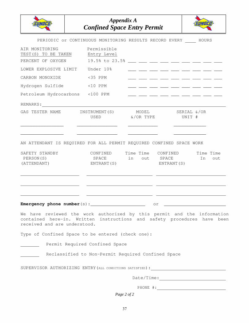
PERIODIC or CONTINUOUS MONITORING RESULTS RECORD EVERY HOURS
AIR MONITORING Permissible TEST(S) TO BE TAKEN Entry Level
PERCENT OF OXYGEN 19.5% to 23.5% ___ ___ ___ ___ ___ ___ ___ ___ ___
LOWER EXPLOSIVE LIMIT Under 10% ___ ___ ___ ___ ___ ___ ___ ___ ___
CARBON MONOXIDE <35 PPM ___ ___ ___ ___ ___ ___ ___ ___ ___
Hydrogen Sulfide <10 PPM ___ ___ ___ ___ ___ ___ ___ ___ ___
Petroleum Hydrocarbons <100 PPM ___ ___ ___ ___ ___ ___ ___ ___ ___ REMARKS:
GAS TESTER NAME INSTRUMENT(S) MODEL SERIAL &/OR USED &/OR TYPE UNIT #
________________ _______________ ___________ ____________
________________ _______________ ___________ ____________ AN ATTENDANT IS REQUIRED FOR ALL PERMIT REQUIRED CONFINED SPACE WORK SAFETY STANDBY CONFINED Time Time CONFINED Time Time PERSON(S) SPACE in out SPACE In out (ATTENDANT) ENTRANT(S) ENTRANT(S)
Emergency phone number(s): or
We have reviewed the work authorized by this permit and the information contained here-in. Written instructions and safety procedures have been received and are understood.
Type of Confined Space to be entered (check one):
Permit Required Confined Space
Reclassified to Non-Permit Required Confined Space
SUPERVISOR AUTHORIZING ENTRY(ALL CONDITIONS SATISFIED):
Date/Time:
PHONE #:
Page 2 of 2

Safety and Security Manual for Contractors Confined Space Entry
Effective: 07/01/08
38
Appendix B Confined Space Attendant Training For Permit Required Entry
As an attendant, you must know: I. The hazards in the space:
1. Gasoline What is it? Gasoline is a flammable liquid. It consists of Petroleum Hydrocarbons. It does
contain some highly hazardous chemical such as Benzene, Toluene and Xylene. It is clear to pinkish in color and has a sweet smell.
Effects of Exposure: Limits: 300 ppm – Short Term Exposure Limit (STEL) (15 minutes) 100 ppm – Time Weighted Average (TWA) (8 hours)
Gasoline at high air concentrations may cause irritation of the eyes, nose and throat. At higher levels, dizziness and loss of balance can occur. Very high concentrations can cause unconsciousness, coma and possibly death. Gasoline is a mild skin irritant and can cause temporary pain when coming in contact with the eyes. However, no permanent damage can be expected.
2. Oxygen Depletion Oxygen content must be maintained between 19.5 and 23.5%. This can be read on the Gas Tech meter provided by the technician. The instrument will alarm when the limits have been exceeded. The technician will set up the equipment to monitor continuously.
3. Physical Hazards Heat or cold extremes. Slips, trips and falls which result in cuts, bruises, broken bones or unconsciousness.
II. As an attendant, responsibilities include: 1. Continuously maintain an accurate count of authorized entrants into the space. This can be done using the sign-
in/sign-out log attached to the permit. 2. Remain outside the permit space during entry operations until relieved by another attendant. You must NOT
enter the space to rescue someone. You can only use the retrieval device if it is on place. If you cannot make a rescue without entering, then you must call emergency rescue (usually the local fire department). The number will be listed on the permit under the confined space section.
3. You must be in communication with the entrant at all times. This can be done through verbal or visual communications at the sump.
4. You must visually monitor the inside and outside of the space to determine if it is safe for entrants. If you detect any of the following, you must call for an immediate evacuation of the space:
a. If the Gas Tech meter alarms at: > 100 ppm total hydrocarbons. < 19.5% or > 23.5% oxygen.
b. If you detect any behavior changes by the entrant that might be related to gasoline (see Section I above).
c. If you cannot remain in the area or perform all of these duties. d. If you notice any dangerous condition in the space.
5. Summon the rescue and other emergency services needed. Again, remember that you must not enter the space. Only trained rescue personnel may perform entry rescue.
6. You must warn unauthorized persons that they must stay away from the permit space. If an unauthorized person has entered the space, you must again inform them that they must exit immediately.
7. You may NOT perform any other duties while an entrant is in the space. It is not acceptable to be pumping gas and monitoring the confined space at the same time.
I understand the above information. Name (Print): _______________________ Signature: ___________________________ Date: ______________

Safety and Security Manual for Contractors Confined Space Entry
Effective: 07/01/08
39
Appendix C
Permissible Exposure Limits (PEL) and Respiratory Protection

Safety and Security Manual for Contractors Crane, Rigging and Hoisting Safety
Effective: 07/01/08
40
CRANE, RIGGING AND HOISTING SAFETY 1.0 PURPOSE:
This procedure describes the actions to be taken prior to and during use of cranes, rigging and hoisting. It is for use by employees and contractors.
2.0 SCOPE:
This procedure applies to all Contractor and Sub-Contractor personnel working at a Sunoco location in which a crane or other hoisting equipment is in use.
3.0 RESPONSIBILITY:
The Retail Engineering, Construction and Maintenance Management Team is responsible for the management and implementation of this procedure. Contractors are responsible for the knowledge of, and adherence to, these procedures. This procedure is included in the “Safety and Security Manual for Contractors”.
4.0 REFERENCES:
• 29 CFR 1926 Subpart N: Cranes, Derricks, Hoists
• 29 CFR 1910 Subpart N: Materials Handling
• 29 CFR 1910.184 Slings
• ANSI Standards – B301.1 Jacks, .2 Overhead and Gantry Cranes, .5 Mobile and Locomotive Cranes, .6 Derricks, .7 Base Mounted Drum Hoists, .9 Slings, .10 Hooks
5.0 PROCEDURE:
Retail Engineering, Construction and Maintenance employees and contractors use a variety of lifting equipment ranging from hoists to “cherry pickers” and 125 truck cranes. This equipment is used to lift and set tanks, roof-mounted HVAC and Refrigeration equipment, pre-fabricated buildings, etc. The contractor and equipment operator are responsible for meeting all applicable OSHA and ANSI standards, including providing Sunoco with the following information as requested: • Copy of Lift Plans. • Copy of Rigging Diagrams. • Proof of Operator Training. • Copy of Crane Safety Procedures. • Proof of Equipment Inspection.
5.1 List of Classifications and Equipment

Safety and Security Manual for Contractors Crane, Rigging and Hoisting Safety
Effective: 07/01/08
41
Lifts are classified based on the weight of the load and the proximity of operating equipment.
• Critical Lifts - Lifts of 40 tons or greater. Lifts over critical operating equipment. (Lifts handled by Heavy Equipment Operators (HEOs) only or qualified contractor personnel).
• Heavy Lifts - Lifts greater than 15 tons but less than 40 tons. Lifts using swinging cranes. (Lifts handled by HEOs only or qualified contractor personnel).
• Major Lifts - Lifts greater than 6 tons but less than 15 tons. (Lifts handled by Light Equipment Operators.)
• Personnel Lifts – Use of suspended personnel baskets. (Lifts handled by HEOs only or qualified contractor personnel).
• Minor Lifts - Lifts of 6 tons or less. (Lifts handled by Light Equipment Operators or anyone familiarized with overhead hoist and trolley.)
5.2 Equipment Operator Qualifications
• Crane operators are to be trained and qualified in the safe use of cranes and other
mobile hoisting equipment. The contractor is responsible for determining who needs to be trained and having personnel qualified assigned to operate cranes and other hoisting equipment. The lift type mentioned above will indicate personnel qualification.
• The operator of equipment traveling over public highways must have the proper drivers license for the class of vehicle being used.
5.3 General Procedures for Performing Lifts with Cranes.
5.3.1 Method and Safety Considerations for Critical lifts, Heavy Lifts and Personnel Lifts. A lift plan is to be used for selecting a crane and making a lift. The contractor and equipment operator are responsible for completing the lift plan. Some of the information that is to be included in the lift plan is listed below: Load and Lift Data • Dimension, weight, center of gravity and configuration of the piece to be
lifted.
• Lateral and overhead clearance.
• Load restriction on floors, structures and access roads. Possibility of underground structures which may be damaged. Soil capacity (holes, rocks, soft ground) and requirement for mats or cribbing. Examination of site to assure outriggers and mats can be accommodated.

Safety and Security Manual for Contractors Crane, Rigging and Hoisting Safety
Effective: 07/01/08
42
• Once the crane is selected, determine the crane position that provides the most favorable operating radius, boom length, boom clearance and required boom height.
Crane Capacity Considerations • Select a crane using the Manufacturer’s safe load chart based on the load
to be handled, the work radius and boom length. Crane charts are to be used with each specific type of equipment. The crane generally cannot be selected based solely on the weight of the load. Crane charts are different for each type of crane.
• The total load weight is to include the weight of the equipment being lifted, sling weight, hook block weight and load handling devices weight.
Rigging Diagram • Rigging diagrams are to be developed by the contractor and equipment
operator for all heavy and critical lifts.
5.3.2 General Safety Considerations
Work Near Overhead Electrical Cables
• Any vehicle that is capable of contacting overhead electrical lines must be operated so that at no time any part of the crane or load comes closer than 10 feet to the overhead lines. This would include vehicles capable of being elevated such as cranes cherry pickers and vehicles transporting high loads.
• Sites with overhead power lines shall be evaluated by the Sunoco Representative and contractor at the pre-construction meeting.
• The Contractor shall contact the local utility company to arrange for their inspection of and requirements for the de-energizing/protection of any overhead power line on the site prior to the work.
• If a safe distance cannot be maintained (at least 10 ft.) from power lines, qualified personnel (trained utility company personnel or approved utility contractors) and appropriate equipment can be used to de-energize, isolate, and sleeve the lines.
However, under any of the following conditions, the clearance may be reduced: • If the vehicle is in transit, with its structure lowered, it may come within 4
feet of energized lines. However, if the voltage is above 50 Kv, the distance must be increased 4 inches for each 10 Kv above 50 Kv.
• If insulating barriers are installed that will prevent contact with the line. • If the boom is insulated for the voltage involved and the aerial lift is being
performed by a qualified person.

Safety and Security Manual for Contractors Crane, Rigging and Hoisting Safety
Effective: 07/01/08
43
Whenever vehicles or mechanical equipment are being operated near overhead lines, and the lines have not been de-energized and grounded, no person standing on the ground may approach or contact the vehicle or equipment unless:
• The person(s) is using protective equipment rated for the voltage: or • The equipment is located so that no uninsulated part of its structure can come
closer to the line than permitted.
General Requirements • Personnel shall wear the appropriate PPE when working around a crane
(ex. safety/steel toed boots, gloves, hard hats, and safety glasses). • Only qualified personnel are to operate crane. • Check all rigging equipment before use to be sure that it is in a safe
condition and has been inspected. The contractor and equipment operator are responsible for checking equipment.
• Be sure that the daily checklist has been completed.
Soil, Footing and Surface Conditions
Visually inspect the work area for obvious problems (e.g. undermining, poorly compacted soil, unreinforced or damaged concrete, etc.). Load on underground piping is to be considered when traveling and setting up cranes. Underground piping is to be identified and load conditions are to be evaluated to determine if weight imposed by total lift will damage piping.
Use sufficient cribbing so that the load is properly distributed.
When lifting near an excavation, special care must be taken to prevent a cave-in. Equipment should be a minimum of two feet from the edge of the excavation. Special care must be taken if the equipment is in excess of 20,000 pounds.
Note: The concentrated weight created by an outrigger can result in a cave-in at an excavation. Consider cribbing under outriggers that are close to the excavation in order to distribute this weight.
Transporting Cranes and Relocating Cranes On-Site
• Cranes being transported over public roads or relocated on the site must follow all motor vehicle regulations. Over-the-road transit of cranes shall be accompanied by an escort. All crane components shall be secured before transporting begins.
• All mobile equipment (cranes, vac trucks, forklifts, high reach trucks, etc.) must have a spotter/walker.

Safety and Security Manual for Contractors Crane, Rigging and Hoisting Safety
Effective: 07/01/08
44
• The spotter should be someone designated by the contractor granting permission to maneuver the equipment, but does not need to be an Operator.
• Prior to maneuvering the equipment, the spotter and the driver should walk the path and discuss any limitations of the equipment (turning radius, center of gravity, braking system, obstacles, soil conditions, etc.) and identify any areas of specific concern. Some maneuvers may require more than one spotter.
Lifting and Rigging Practices
• The Contractor shall designate a competent person who shall inspect all machinery and equipment prior to each use, and during use, to make sure it is in safe operating condition. Any deficiencies shall be repaired, or defective parts replaced, before continued use.
• Check the load for balance immediately upon placing a strain on the cables or sling. Make sure cables or slings are not frayed or cut. Make sure cables or slings are not kinked or twisted around each other. Make the lift slowly to avoid shock and damage.
• Use hand signals for all lifts. Only one qualified person should give signals to the crane operator.
• Guide ropes (tag lines) must be used for steadying loads.
• Personnel must stand well away for all suspended loads and cables that are under strain.
• A sling shall not be pulled from under the load while the load is resting on it.
• Cranes and equipment being used to hoist materials or personnel overhead will be roped off with barrier rope for a 20 foot radius beyond the Boom Operating Radius.
Night Lifts
Extra precaution must be taken for lifts at night, to include:
• Sufficient lighting.
• Radio communication for all involved in the lift.
• Adequate manpower to direct all aspects of the lift.
5.3.3 Inspection and Testing
Checklists are to be used for inspecting and testing mobile cranes and hoists:

Safety and Security Manual for Contractors Crane, Rigging and Hoisting Safety
Effective: 07/01/08
45
Pre-Lift Check - to be completed by the equipment operator prior to each lift.
Daily Checklist - to be completed by the equipment operator prior to each day’s use of the equipment. This checklist should be retained for one year.
Annual Inspections – The contractor is responsible for conducting these inspections. A thorough, annual inspection of the hoisting machinery shall be made by a competent person, or by a government or private agency recognized by the U.S. Department of Labor. The employer shall maintain a record of the dates and results of inspections for each hoisting machine and piece of equipment. Annual inspection records are to be retained for two years.

Safety and Security Manual for Contractors D.O.T. Regulations - Contractors
Effective: 07/01/08
46
D.O.T. REGULATIONS - CONTRACTORS 1.0 PURPOSE:
This procedure describes Department of Transportation (D.O.T.) regulations that Contractors must follow in their daily job performance.
2.0 SCOPE:
This procedures applies to all Contractor and Sub-Contractor employees who fall under the D.O.T. Guidelines
3.0 RESPONSIBILITY:
The Contractor is responsible for the management of these procedures. Each individual driver is responsible for the knowledge of and adherence to D.O.T. Regulations. This procedure is for use by drivers that fall under the Department of Transportation Guidelines.
4.0 REFERENCES: 49 CFR Vol. 4, Chapter III, Federal Motor Carrier Safety Administration 5.0 PROCEDURE
5.1 Contractors are responsible for complying with all Department of Transportation regulations:
• Each driver is responsible for daily hours.
• Each driver is responsible for knowledge of regulations.
• Each driver is responsible for all paperwork.
• Each driver should refer to the latest edition of the Federal Motor Carrier Safety Regulations Pocket Book for further details.
4.2 D.O.T. Requirements include, but are not limited to the following:
• Maximum Driving and On Duty Time
Each driver must have 8 consecutive hours off-duty before: - Driving more than 10 hours. - Are on duty, including all driving, for more than 15 hours.
• Outside Inspections & Service
Each driver must inspect and maintain all vehicles. Any receipts for service and repair work in the vehicle must be kept in the D.O.T. file. Most records are required to be kept for a minimum of one year.

Safety and Security Manual for Contractors D.O.T. Regulations - Contractors
Effective: 07/01/08
47
• Daily Vehicle Condition Inspections
Every driver must conduct a Pre-Inspection before each day's work on each vehicle operated. A legible copy of the last vehicle inspection report is to be carried on the vehicle.

Safety and Security Manual for Contractors Electrical Safety Procedures
Effective: 07/01/08
48
ELECTRICAL SAFETY PROCEDURES 1.0 PURPOSE:
These Procedures describe how electrical work is to be performed by Retail Engineering, Construction and Maintenance utilizing safe maintenance procedures.
2.0 SCOPE:
This procedure covers all Contractor and Sub-Contractor employees working at a Sunoco location
3.0 RESPONSIBILITY:
The Retail Engineering, Construction and Maintenance Management Team is responsible for management and implementation of these work instructions. Employees and Contractors are responsible for knowledge of, and adherence to, these instructions. This procedure is included in the “Safety and Security Manual for Contractors”.
4.0 REFERENCES: 29 CFR 1926 Subpart K – Electrical
29 CFR 1910 Subpart S - Electrical
5.0 PROCEDURE
5.1 Only qualified employees may work on or with exposed energized lines or parts of
equipment. Only qualified employees may work in areas containing unguarded, un-insulated energized lines or parts of equipment operating at 50 volts or more.
Qualified persons (i.e. those permitted to work on or near exposed energized parts) shall, at a minimum, be trained in and familiar with the following:
• The skills and techniques necessary to distinguish exposed live parts from other parts of electric equipment.
• The skills and techniques necessary to determine the nominal voltage of exposed live parts, and
• The clearance distances specified in 1910.333(c) and the corresponding voltages to which the qualified person will be exposed.
5.2 Voltage Testers and Detectors
Safety in electrical work depends on knowing what is energized, and what is not. Such determinations are typically made using voltage testers or voltage detectors. Voltage testers indicate the approximate voltage, while detectors show only the presence of voltage. It is important to select the correct tester or detector for the job. For example, a tester

Safety and Security Manual for Contractors Electrical Safety Procedures
Effective: 07/01/08
49
intended for use on low voltages might explode if it were used on a 14 KV line. Similarly, a high voltage detector would give little, if any, indication on a 220 volt line. A typical voltage tester has two probes that are touched to the conductors when taking a voltage level reading. Many testers will register the approximate values of AC or DC voltage. By contrast, most voltage detectors have small neon bulbs that glow when they are placed near an AC source. Voltage detectors should never touch the conductor at all, since an electrical shock could result. As a general rule, voltage detectors do not detect DC voltage. They should not be used to verify that DC equipment is de-energized. The general procedure for using a voltage detector or tester to determine if a circuit is de-energized is as follows: (a) Test the testing device on a known energized source to see if it works. (b) Check the de-energized circuit. (c) Test the testing device again to be sure it still works.
Only trained and qualified employees may perform voltage testing.
5.2 On The Job Safety Following safe work procedures on the job will help protect you from injury. Safe procedures for performing electrical work may include the following: - Check the Panel Legend or Index, breaker, and tag to make sure you are
working on the right circuit and equipment. - Make sure that the equipment can be de-energized without affecting other
equipment that may be on the same circuit. - Make sure the equipment has been put in safe condition so that it cannot be
energized while it is being worked on. Lock-out/Tag-out must be used, unless performing troubleshooting. Only Qualified Personnel using strict procedures may conduct troubleshooting or work on live energized circuits.
- Prepare the area where the work is to be done, possibly using rubber mats on
the floor. - Make sure there is a designated safety person, if required.

Safety and Security Manual for Contractors Electrical Safety Procedures
Effective: 07/01/08
50
- Use protective gloves approved for the equipment voltage. Inspect the glove prior to use.
- Check the equipment to determine what is energized and what is not. - Cover exposed energized conductors to minimize shock hazards. - Avoid wearing metal jewelry and other metal objects that could conduct
electricity. - Circuits should always be properly grounded and bonded in accordance with
the latest National Electric Code regulations. To assure grounding and bonding, temporary extension cords utilized at construction sites should include the use of ground fault circuit interrupters.
5.3 Basic Electrical Concepts
Like heat or light, electricity can easily flow through some materials. These materials are called conductors. Others, called insulators, have a great deal of resistance to electrical flow. All materials, even conductors, resist the flow of electricity to some degree. The flow of electrical energy is called current. Current will only flow if a complete path or circuit is provided for it to follow. The electrical pressure that makes the current flow is voltage. A conductor connected to a voltage source is energized. The electrical resistance of a conductor can cause it to get hot when a current flows through it. There must be enough voltage applied to a conductor to overcome the conductor's resistance before current will flow. Electrical circuits are often grounded for safety. Grounding provides a safe path for current if a tool or its power cord is damaged.
5.4 Personal Injuries
Burns and shock are the most common injuries caused by contact with electrical hazards. Heat produced by arcs and by the resistance of conductors can cause painful burns. Four factors influence how severe a shock will be.
- The voltage involved. Generally, as little as 30 volts is enough to push current
through your body.
- The amount of current available from the source. Plant lighting and equipment circuits have sufficient current to produce a fatal shock.

Safety and Security Manual for Contractors Electrical Safety Procedures
Effective: 07/01/08
51
- The path the current takes through your body. A current path through your
heart is more dangerous than a path that does not pass through your heart.
- The resistance of your skin. Wet skin has less resistance and will contribute to a stronger shock than dry skin.
5.5 Avoiding Electrical Hazards
When working in areas where electrical hazards may be present, the following precautions should be taken to avoid electrical hazards.
- Avoid contact with energized conductors. Follow lockout/tagout procedures
for de-energizing equipment before you work on it.
- Avoid overloading circuits. Wiring, power cords, and extension cords are rated to carry only a specified amount of current. Check the amount of current used by your equipment before you plug it in. Use short extension cords whenever possible.
- Ground Fault Circuit Interrupters (GFCI’s) GFCI’s must be used on all portable electric power tools. If GFCI’s are not
used, an Assured Grounding Conductor Program must be used. GFCI’s shall be inspected and tested periodically as required by the manufacturer.
- Avoid contact with high voltage equipment.
Observe the special warning signs at high voltage areas. Do not enter high voltage areas without specific instructions.
- Avoid using damaged equipment. Inspect cords on power tools and
equipment for crushed or bare conductors and damaged plugs. Check equipment ground connections. Damaged equipment shall be immediately taken out of service and discarded or repaired.
- Do not wear conductive jewelry or apparel and use the appropriate PPE (ex.
electrically rated gloves, faceshield, arc flash protection, etc.) - Doors, guards, or covers shall be in place to protect personnel from contact
with exposed energized circuits.
5.6 Overhead Power Lines
- Anyone not qualified to work near exposed energized or de-energized overhead lines must stay a minimum of ten feet away from any unguarded equipment.
- Vehicles and mechanical equipment must also maintain a ten-foot safe
distance. This includes your bucket on the bucket truck.
- Tree trimmers must be qualified and have sufficient knowledge of the construction and operation of overhead power lines in order to prevent

Safety and Security Manual for Contractors Electrical Safety Procedures
Effective: 07/01/08
52
accidentally contacting or cutting a power line.
- Sites with overhead power lines shall be evaluated by the Sunoco Representative and contractor at the pre-construction meeting.
- The Contractor shall contact the local utility company to arrange for their inspection of and requirements for the de-energizing/protection of any overhead power line on the site prior to the work.
- If a safe distance cannot be maintained (at least 10 ft.) from power lines,
qualified personnel (trained utility company personnel or approved utility contractors) and appropriate equipment can be used to de-energize, isolate, and sleeve the lines.
5.7 Protection From Arcs
Arcs are another type of electrical hazard associated with electrical equipment. An electrical arc can burn or blind you. A common cause of arcs is pulling fuses while they are carrying a load. The procedure for preventing arcing while pulling fuses is as follows:
(a) De-energize the circuit by opening its breaker.
(b) Use an approved fuse puller.
(c) Pull each fuse with a sharp tug so that both ends come out at once.
If the circuit cannot be de-energized, unload the fuse box by turning off whatever is powered by that line. If there is no current draw, an arc is less likely. The proper tool for removing a fuse is a fuse puller. Fuse pullers are insulated and keep your hands away from the work to minimize the chances of injury, should an arc occur.
5.8 The One-Hand Rule
Follow the One-Hand Rule whenever you work on live circuits. Otherwise, electricity passing from arm to arm may pass through vital organs, leaving you paralyzed or dead. - Work with one hand and keep the other at your side or in your pocket.
5.9 Summary of Electrical Safety Basics
Everyone wants to get the job done. When you deal with electricity, however, don't forget the basics. Safe work conditions, safe work procedures and your personal sense of responsibility are your best bets to avoid hazardous shock. Accidents don't have to happen if you remember these simple guidelines:

Safety and Security Manual for Contractors Electrical Safety Procedures
Effective: 07/01/08
53
- Be alert as a matter of habit.
- If you see something you're not sure about, have it checked out.
- If you don't know a procedure, ask someone who does.
- Questions about electricity are never a waste of time. - Use power tools as they are designed to be used. Plastic bodied power tools
are usually double insulated and do not require grounding. Battery-powered tools use lower operating voltages that reduce the danger of shock.
- Use approved lighting in wet areas and explosive atmospheres. These areas
may require special lighting with low voltage or explosion proof rating. Air-operated power tools may also be required.
- Maintain at least 10 feet of clearance between power lines and mobile
equipment. Avoid contact with equipment operating close to power lines.
- Avoid direct contact between the two connections on a battery. Direct contact can cause a large flow of current and may cause the battery to explode.
- Use bonding straps to discharge and prevent static charges during transfer of flammable materials from one container to another.
- Remove jewelry and other conductive objects before starting work.
- Avoid aluminum ladders. They conduct electricity and are not suitable for work around electrical circuits and equipment. Follow your department’s procedures for selecting a ladder.
5.10 Responding to Electrical Emergencies
The first thing to remember is that you could become a victim yourself. Follow your department’s emergency response procedures. Generally, turn off the power before touching any victims, then call for help. Victims may require cardiopulmonary resuscitation (CPR). You may want to be trained in first aid and emergency procedures so you are prepared to respond to emergencies with injuries.
5.11 Summary
In a properly designed and maintained system, electrical current is safely channeled in controlled paths. But faulty insulation, careless handling or improper grounding allow the current to get out of control. Your body may provide the path to ground that allows electricity to seek its source. Electricity is a silent, invisible force that can kill without warning if its dangers are ignored. Treat this powerful energy with caution and respect, and you need not fear it.
Safety and Security Manual for Contractors Emergency Shut-Off Valve Operation
Effective: 07/01/08
54
EMERGENCY SHUT-OFF VALVE OPERATION 1.0 PURPOSE:
This Procedure describes the operating procedures for Fuel Dispenser Emergency Shut-Off Valves. It is for use by Retail Engineering, Construction and Maintenance and anyone else who is servicing a fuel dispenser.
2.0 SCOPE:
This procedure covers all Contractor and Sub-Contractor employees who must service a fuel dispenser at a Sunoco location
3.0 RESPONSIBILITY:
The Retail Engineering, Construction and Maintenance Management Team is responsible for management and implementation of these work instructions. Retail Engineering, Construction and Maintenance employees and contractors are responsible for knowledge of, and adherence to, them.
4.0 REFERENCES:
Not Applicable 5.0 PROCEDURE:
When use of the Emergency Shut-Off Valve on fuel dispensers is required, the instructions on the following procedure must be followed.
In the case of an EMERGENCY, the Emergency Stop Button (E-Stop) should be used if available. If an E-Stop button is not in place, the circuit breakers for the submersible turbine pumps and dispensers should be utilized as the primary emergency shut-off device. The Dispenser Shut-Off Valve should only be utilized as the primary emergency shut-off device when it has been determined that it is functional and stops the product flow.

Safety and Security Manual for Contractors Emergency Shut-Off Valve Operation
Effective: 07/01/08
55

Safety and Security Manual for Contractors Excavations
Effective: 07/01/08
56
EXCAVATIONS 1.0 PURPOSE:
This policy lists the general requirements for all excavations.
2.0 SCOPE:
This procedure covers all Contractor and Sub-Contractor employees working in or around excavations at a Sunoco location.
3.0 RESPONSIBILITY:
The Retail Engineering, Construction and Maintenance Management Team is responsible for management of and communication of this procedure. All employees and contractors involved in excavations are responsible for adherence to this policy. This procedure is included in the “Safety and Security Manual for Contractors.”
4.0 REFERENCES:
29 CFR 1926 Subpart: Excavations 5.0 PROCEDURE:
5.1 General Excavation Requirements:
• A competent person must be available onsite and in charge of all excavations for when greater than 5 ft. deep. Excavations greater than 5 ft. may be classified as a confined space.
• All excavation procedures and protective measures (sloping, shoring, etc.) must comply with 29 CFR 1926.652 – Requirements for Protective Systems.
• Approved barricades must be erected at the edge of all open trenches and excavations as required.
• Spoils, materials, and vehicles must be kept at least 2 feet from the edge of the excavation?
• All surface encumbrances must be removed or supported to safeguard employees.
• The location of underground utilities and other installations, such as sewer, power lines, water lines, etc. must be determined prior to initiation of excavation.
• Utility companies or owners shall be contacted and advised of proposed work prior to initiation of projects. Use One-Call, Miss Utility, and any other available notification system to notify utilities as required.
• When excavations approach the approximate location of underground installations, the location of the installation shall be located using safe and acceptable methods.

Safety and Security Manual for Contractors Excavations
Effective: 07/01/08
57
• Proper access and egress must be provided for excavations 4 ft. or more (ladder within 25 feet and extends 3 ft. above) Structural ramps used by employees for entry and egress from excavations must be designed by competent persons.
• No one shall be permitted underneath loads handled by lifting or digging equipment.
• The atmosphere in excavations will be tested prior to entry, if some sort of contamination is suspected. Examples would include a known history of spills or leaks, the discovery of stained or discolored soil, or evidence of former piping. Periodic or continuous testing will be performed based on initial test results and the type of hazard posed.
• Ventilation shall be provided, when necessary to assure that workers are not exposed to atmospheres containing concentrations of flammable gases in excess of 10% of the Lower Explosive Limit (LEL). Entry will be permitted when the oxygen level is within the acceptable range of 19.5 to 23.5 % and the organic vapor level is less than 100ppm.
• Monitoring of the atmosphere in excavations should be performed continuously to assure that the atmosphere remains safe and the readings recorded a minimum of once per hour until the job is completed.
• No one may work in excavations where water has accumulated or is accumulating unless adequate precautions have been taken to assure protection of workers form the hazards of such accumulation.
• Emergency rescue equipment, such as rescue baskets, SCBAs or safety harnesses and lines, will be readily available and used while work in excavations is being performed.
• Daily documented inspections of sites must be performed by a competent person to determine if cave-ins, failures of protective systems, hazardous atmospheres, or such hazardous conditions have developed. Such inspections should be performed periodically during each shift that work is being performed. If questions of safety arise as a result of an inspection, everyone must be removed from, or prevented from, entering the excavation until the site is deemed safe for entry by a competent person.
• All excavations greater than 5 feet deep are to be accomplished by one of the following practices:
a) Shoring
b) Cutback of slopes
c) Special engineering designs
d) Out of hole installation

Safety and Security Manual for Contractors
Filter Changing Effective: 07/01/08
58
FILTER CHANGING 1.0 PURPOSE:
This procedure describes the safe operating procedures for changing gasoline, diesel, kerosene or E-85 dispenser filters. The purpose of this procedure is to reduce the risk of exposure to the product and vapors while safeguarding employees, company property, and the community while complying with federal, state, and local environmental and safety regulations.
2.0 SCOPE:
This procedure covers all Contractor and Sub-Contractor employees who change gasoline dispenser filters at a Sunoco location.
3.0 RESPONSIBILITY:
The Maintenance Management Team is responsible for management and implementation of these work instructions. Technicians are responsible for knowledge of, and adherence to this procedure when changing filters. This procedure applies to Technicians, Contractors, Dealers and anyone else who is changing filters and is included in the “Safety and Security Manual for Contractors.” It is the responsibility of all employees and those working for Maintenance to follow the steps described in this procedure while changing dispenser filters. • It is the responsibility of all employees and those working for Maintenance to report any
skin exposures to petroleum based product or other related injuries/illnesses to their supervisor on the day of the exposure incident.
• It is the responsibility of Management Team to ensure that employees are informed of this procedure and work within the guidelines described.
• It is the responsibility of the Branded Marketing Health and Safety Office to maintain and update this procedure as needed. The Health and Safety Manager, or their designee, will conduct industrial hygiene exposure monitoring on a regular basis.
4.0 REFERENCES:
Not Applicable 5.0 PROCEDURE:
This procedure describes the step-by-step task of changing dispenser filters. Each step described below must be followed to ensure the safety of people, property, and the environment. The priority while changing dispenser filters is employee safety; following the steps below will ensure minimal exposure to petroleum based product and vapors. 5.1 Follow Barrier Protection procedure to secure the dispenser and put on the required
personal protective equipment: Safety (Rubber or Nitrile) gloves and safety glasses or chemical goggles.

Safety and Security Manual for Contractors
Filter Changing Effective: 07/01/08
59
5.2 Remove both dispenser covers to increase ventilation.
5.3 Turn off ALL crash valves to stop product flow to the dispenser.
5.4 Try to position yourself to work upwind from the dispenser and closed container(s) to
reduce exposure to petroleum vapors. 5.5 Turn on the dispenser to activate all submersible tank products.
5.6 To relieve pressure above the crash valve, squeeze the nozzle trigger and dispense
product into a closed container, such as the calibration can. This will verify that the crash valve is operational and holding.
5.7 Slowly loosen the filter and let the product collect in a small container under the
filter. Dump the product into a CLOSED container (you can use the calibration can). This step should be repeated as often as needed for each filter to ensure that smaller amounts of product are emptied each time to reduce risk of spilling.
5.8 Slowly remove the emptied filter and place it upside-down in a closed collection can
where it can drain and product can be collected.
5.9 Verify the old filter gasket is removed.
5.10 Use a permanent marker to mark the installed date and initial the new filter.
5.11 Oil the O-ring of the new filter before installation. This practice will increase safety and ease during future removal of the filter.
5.12 Tighten the new filter in place. Repeat steps 6-12 for each filter.
5.13 Open the crash valve.
5.14 Remove air in the lines by squeezing the trigger nozzle and dispense product into a
closed container.
5.15 Check for leaks at the filter.
5.16 Replace dispenser covers. Repeat steps 1-16 for each dispenser.
5.17 Discard filters in accordance with local environmental regulations at each service station. See Section 6.0 for Spent Dispenser Filter Management Summary.
5.18 Employees should work at a steady pace without being rushed while changing
petroleum based dispenser filters. By taking more time, the task can be completed safely without spilling product, and vapor exposure will be reduced over time.

Safety and Security Manual for Contractors
Filter Changing Effective: 07/01/08
60
5.19 If product comes in contact with skin or clothing, the employee should change clothes
(if clothing was contaminated) and wash the exposed skin area with soap and water as soon as possible. The employee is required to notify their supervisor of this incident.
6.0 TRAINING: Employees and those working for Maintenance will be provided a copy of this procedure and on the job training of the task, in addition to personal protective equipment training.
7.0 PROCEDURE EVALUATION:
This procedure will be evaluated by the Health and Safety Manager, or their designee, in conjunction with Industrial Hygiene monitoring, or as otherwise needed.
8.0 SPENT DISPENSERS FILTERS MANAGEMENT SUMMARY Spent petroleum based dispenser filters that have been in service, including ethanol or MTBE service, are Toxicity Characteristic Hazardous Waste for Benzene (D018). The waste management guidance below is summarized from the Sunoco Standard, Conditionally Exempt Small Quantity Generator - State Specific Requirements (ENV-STD-005). Therefore, changes in that standard should be incorporated into this procedure. 8.1 Assumptions/Conditions for the spent dispenser filter management
1. The service stations generate no more than a total of 100kg (roughly 220 pounds) of hazardous wastes in a calendar month. This would include all hazardous waste generated. However, the amounts of used oil or universal waste lamps or batteries are not included in the 220 pounds monthly limit (as long as the lamps are managed as universal waste). If a station generates greater than the 220 pounds per month the Conditionally Exempt Small Quantity Generator (CESQG) option is not available, and the station must follow more stringent small quantity generator (SQG)or large quantity generator (LQG) requirements. However, the scrap metal option is still available even if a facility is a small quantity or large quantity generator.
2. All spent filters have been sufficiently drained of free liquids. Neither the
CESQG option of disposal with the municipal trash nor the scrap metal destined for recycling options allow filters to contain free liquids or have liquids dripping from them.
CESQG Option - If the federal CESQG option is available in the state the service station is located and the state allows disposal of drained filters in the municipal trash, that is the most cost effective and recommended option.
8.2 State Summaries Scrap Metal Destined for Recycling States:
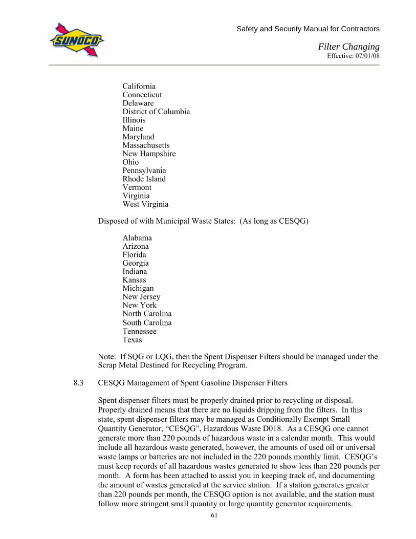
Safety and Security Manual for Contractors
Filter Changing Effective: 07/01/08
61
California Connecticut Delaware District of Columbia Illinois Maine Maryland Massachusetts New Hampshire Ohio Pennsylvania Rhode Island Vermont Virginia West Virginia Disposed of with Municipal Waste States: (As long as CESQG) Alabama Arizona Florida Georgia Indiana Kansas Michigan New Jersey New York North Carolina
South Carolina Tennessee Texas Note: If SQG or LQG, then the Spent Dispenser Filters should be managed under the Scrap Metal Destined for Recycling Program.
8.3 CESQG Management of Spent Gasoline Dispenser Filters
Spent dispenser filters must be properly drained prior to recycling or disposal. Properly drained means that there are no liquids dripping from the filters. In this state, spent dispenser filters may be managed as Conditionally Exempt Small Quantity Generator, “CESQG”, Hazardous Waste D018. As a CESQG one cannot generate more than 220 pounds of hazardous waste in a calendar month. This would include all hazardous waste generated, however, the amounts of used oil or universal waste lamps or batteries are not included in the 220 pounds monthly limit. CESQG’s must keep records of all hazardous wastes generated to show less than 220 pounds per month. A form has been attached to assist you in keeping track of, and documenting the amount of wastes generated at the service station. If a station generates greater than 220 pounds per month, the CESQG option is not available, and the station must follow more stringent small quantity or large quantity generator requirements.

Safety and Security Manual for Contractors
Filter Changing Effective: 07/01/08
62
However, the scrap metal destined for the recycling option is still available. In select states per Section 6.2, as a CESQG, properly drained spent dispenser filters can be put in with the service station’s municipal trash, as long as it does not exceed the 220 pounds per month limit.
(See CESQG Hazardous Waste Tracking Chart on following page)
8.4 Scrap Metal Destined for Recycling Option
In states that do not allow CESQG’s to place hazardous waste in the municipal trash, the spent dispenser filters will be managed as scrap metal destined for recycling. For this option, all spent filters must be sufficiently drained of free liquids. Only spent filters are to be placed in the containers and the containers are to be closed except when adding filters. The containers will have a small amount of absorbent material placed at the bottom to absorb any small drips of fuel that may be released from the filters during transportation. The containers are to have labels with the words “Scrap Metal Destined for Recycling”. Include the DOT Shipping Description (Flammable Solids N.O.S. 4.1 UN1325), and the service station’s name, address and EPA ID number. An example of the label is attached to this document for reference. Containers will be delivered already with absorbents and labels. Containers will be picked up when full or at least once per year. The filters will be transported to a scrap metal recycling facility where they will be reprocessed into new steel. An example label is provided below.

Safety and Security Manual for Contractors
Filter Changing Effective: 07/01/08
63
CESQG Hazardous Waste Tracking Facility DUNS Number: _______________________ Facility Address: __________________________________________________________________________________________
Date Material (Haz Waste Code)
Number Pounds Per Unit Number of Pounds Running Total Pounds Filters Changed By
Dispenser Filters (DO18)
Spent Absorbents (DO18)
Liquid Wastes
Spill Bucket Water (DO18)
Other
Monthly Total – Not to exceed 220 pounds per month CESQG Hazardous wastes that are disposed with Municipal wastes cannot contain any free liquids. Please fax Copies of completed forms to Sunoco Compliance Services Department

Safety and Security Manual for Contractors
Filter Changing Effective: 07/01/08
64
Scrap Metal Destined For Recycling
Exempt From Regulation Under 40 CFR 261.6(a)(3)
Generator’s Name: EPA ID# Address: State: City: Zip Code: Shipping Description: Flammable Solids N.O.S. 4.1 UN1325 Used Fuel Filters – Scrap Metal Destined for Recycling Lab Code: Accumulation: Document: Line No.

Safety and Security Manual for Contractors
Fire Protection Effective: 07/01/08
65
FIRE PROTECTION 1.0 PURPOSE
This procedure is to identify potential fire hazards, provide guidelines to prevent fires and specify fire protection procedures that comply with the requirements of OSHA, NFPA and industry practice.
2.0 SCOPE:
This procedure applies to all Contractor and Sub-Contractor employees working at a Sunoco location.
3.0 RESPONSIBILITY:
The Retail Engineering, Construction and Maintenance Management Team is responsible for the management, implementation and communication of these procedures. All Retail Engineering, Construction and Maintenance employees and contractors are responsible for the knowledge of and adherence to these procedures. This procedure is included in the “Safety and Security Manual for Contractors”.
4.0 REFERENCES:
29 CFR 1926 Subpart F: Fire Protection and Prevention 5.0 PROCEDURE:
5.1 In all cases of fire: • Shut off the source of the product to the fire if it can be accomplished without
endangering yourself or other people. • Notify proper emergency response personnel, i.e. local fire department (911),
manager/supervisor, police. • Evacuate yourself and other people from the work site.
If you are expected to use a portable fire extinguisher in the event of a fire, you will be trained in the operation and use of portable fire extinguishers, and you can then fight incipient stage small fires in your work place. If you have not been trained in the operation and use of portable fire extinguishers on incipient stage fires, DO NOT attempt to fight and put out any type of fire. In no case should you jeopardize your own personal safety when fighting a fire.
5.2 At a minimum, one fire extinguisher (10 lb. ABC) must be readily available, fully
charged, and free from obstructions. Additional fire extinguishers may be required, depending on the size of the site. Fire extinguishers shall be inspected on a monthly and annual basis. The monthly visual inspection shall be recorded on the fire extinguisher tag or a log sheet.. Annually, an outside vender shall perform the annual maintenance inspection.

Safety and Security Manual for Contractors
Fire Protection Effective: 07/01/08
66
Only fight incipient fires. Incipient fires are those in the initial or beginning stage, and which can be controlled or extinguished by portable fire extinguishers, without the need for protective clothing or self-contained breathing apparatus. If the fire is not in its beginning stage, leave the area.
5.3 Fire Loss Reporting:
All fires must be reported and documented in “SIRIS” as required in the Accident, Incident, and Lost Time Injury Investigation Procedures. This report, upon its completion, must be distributed as follows: 1. Retail Engineering, Construction and Maintenance Manager 2. Manager of Health And Safety
5.4 Fire Prevention:
The following are possible fire hazards inside and outside of the service station/food market and the procedures to be taken to eliminate them: Electrical Equipment – Inspect electrical cords routinely and replace frayed areas or loose connections. Use the proper size fuses. Do not overload electrical outlets and do not use three way plugs. Use extension cords only when necessary. Use cords that are in good condition and rated for the use. Ensure that ground connections are secure. Check electrical boxes routinely for overheating. Properly label all control panels. Have electrical connections and motors to electrical equipment checked regularly. Do not use temporary wiring. Do not allow accessory heating equipment or machinery to operate unattended. Flammable Liquids – Keep flammable liquids and all containers used to store them away from electrical panels and outlets, space heaters, furnaces, hot water heaters, and other sources of heat or ignition such as cigarettes and cutting or welding tools. Flammable liquids shall be stored in metal safety cans. Plastic gas cans are not permitted. Handle products containing petroleum hydrocarbons carefully and clean up spills quickly and thoroughly. Use flammable liquids in well ventilated areas only. Store flammable liquids in proper containers only and allow customers to fill only approved containers with gasoline and kerosene. Immediately remove clothing that has absorbed flammable liquids. Ensure that the emergency shut-off switch for gasoline pumps is in working conditions and readily accessible at all times.
Smoking – Smoking by employees and contractors on Owner's premises is prohibited except in areas specifically designated by the Owner's Representative. Designated Smoking areas will not be located within 25 feet of flammable materials, fuel storage facilities, or dispensing equipment. It is not acceptable to walk off the property and smoke in an adjacent property. Smoking areas must be clean and have the appropriate butt container. A fire extinguisher must be readily available. Maintain “No Smoking” and “Shut Off Engine While Refueling” signs at gasoline pumps and enforce these rules. Put cigarettes and matches out before throwing them away in the butt container before leaving the designated smoking area.

Safety and Security Manual for Contractors
Fire Protection Effective: 07/01/08
67
Housekeeping – Maintain proper storage and disposal practices. Keep aisles clean and clear at all times. Keep exit doors unlocked and easily accessible any time someone is in the facility. Do not store trash, crates, or boxes directly outside of exit doors. Dispose of combustible scrap (oily rags, used gasoline absorbent, etc.) in tightly closed metal containers and empty routinely. Do not use or store chemically incompatible substances together. Do not store oxygen cylinders near combustible materials. Clean dust and grease off of equipment routinely.
Space Heaters – Sun strictly prohibits the use of portable heating equipment anywhere on a service station or convenience store property owned, leased or operated by Sun, including the bay areas, sales area, offices, storage rooms, kiosks and rest rooms. Additionally, the National Fire Protection Association prohibits the use of portable heating equipment in and around a service station area.
5.5 Fire Extinguishing Training
Fire extinguishing training is not required for employees whose job duties do not include fire fighting. It is Sunoco’s position that employees at a service station or convenience store should not fight fires. Reference: CFR 1910.156
5.6 Fire Suppression Systems
Where required by local regulations, automatic fire suppression systems should be installed in accordance with appropriate NFPA standards, manufacturers’ instructions and the listing requirements of the system.
5.7 In case of a fire, an employee should:
a. Activate the emergency pump shut off. b. Notify the Fire Department (911 or other emergency number). c. Evacuate the site and make sure all other people are evacuated.
5.8 Stop, Drop and Roll Procedures
If your clothing catches fire, follow this procedure:
- Stop moving. - Drop to the ground - Roll to smother flames.
If someone else’s clothing catches fire, follow this procedure:
- Tell them to stop, drop and roll. - Wrap them in a rug or blanket to smother the flames whether they are standing or
lying and rolling.

Safety and Security Manual for Contractors
Flexible Connector Removal/Handling/Replacement Effective: 07/01/08
68
FLEXIBLE CONNECTOR REMOVAL/HANDLING/REPLACEMENT 1.0 PURPOSE:
This procedure details the requirements for handling of all flexible connectors removed from Sunoco retail sites.
2.0 SCOPE:
This procedure covers all Contractor and Sub-Contractor employees who remove, handle or replace flexible connectors at a Sunoco location.
3.0 RESPONSIBILITY:
The Retail Engineering, Construction and Maintenance Management Team is responsible for the development, implementation, communication and management of this procedure. All Retail Engineering, Construction and Maintenance employees and contractors are responsible for the knowledge of and adherence to this procedure.
4.0 REFERENCES:
Not Applicable 5.0 PROCEDURE:
Some of the flexible connectors are suspected to be defective, and therefore Retail Engineering and Construction is tracking how they are removed, handled and where flexible connectors are sent for further testing and evaluation. 1. Make the site safe and examine for leaks using existing procedures and equipment as
required. 2. Where leaks are found, open manholes, covers, and/or dispenser doors, remove liquid
fuel and/or vapor from the containment area using appropriate spill control equipment and the 12 volt blower system where needed.
3. When hydrocarbon levels are confirmed, by testing, to be below 100 PPM (determined
using the detector tubes and pump, or meter), enter the containment area following Confined Space Procedures. Mark any visible leak locations noted with a PAINTSTIK (Grainger # 2f904 typical) and then take several photographs of the flexible connector, leak locations, containment area, openings in the containment area, damaged containment/piping/equipment, or any other condition of note concerning the incident before attempting any repairs. Cameras should be kept a minimum of 3 feet outside the containment area opening during this process.

Safety and Security Manual for Contractors
Flexible Connector Removal/Handling/Replacement Effective: 07/01/08
69
4. Follow steps 1-3 if no leaks are found as well. Contact the Sunoco Representative for direction on recovery of non-leaking Flexible Connectors. If directed by the Sunoco Representative these connectors are to be removed and saved for further analysis. Total hydrocarbon levels should not exceed 100 PPM for any Confined Space Entry. See Confined Space Procedures for details.
5. When addressing a leaking flexible connector or a non-leaking connector that is to be
saved as a sample, after all photographs are taken, remove the flexible connector carefully without excessive bending beyond the installed configuration. Do not cut the connector or end fittings, place wrenches and backup wrenches only on the end fittings as recommended by the manufacturer, and do not twist or torque the flexible portion of the connector.
6. Photograph the flexible connector and the area from which it was removed immediately
after disconnection and removal from its installed location. Record in these photos any visible leak locations (as marked in step 3 above), bends, damage, or other condition of note.
7. Mark the photographic evidence (Polaroid photos, floppy diskettes, CD’s,
negatives/envelope containing the negatives) with the information listed below. a. Site Duns # b. Date photos were taken c. What sample the photos represent by dispenser #, Tank #, and product. d. Name of the person taking the photos.
8. Store the photographic media in an environmentally controlled area until transferred to the local Retail Engineering, Construction and Maintenance Personnel or Office.
9. Attach a tag (Grainger #4x886 3x6 inch cardboard typical), using Duct Tape if the wire
tie is not practical, to each flexible connector removed to be saved and mark the information below on the tag in permanent marker or ink.
a. Site Duns # b. Flexible connector location (by dispenser # or tank # & product) c. Date of removal d. Name of person filling out tag.
10. While at the site, fill out the information required on the Equipment Transfer Log (see Attachment A) for each flexible connector recovered. Contractors only: Contact Sunoco Maintenance at 1-800-786-9494 to report completion of the work and obtain the name and phone number of the local Sunoco Personnel or Office that the flexible connector(s), Equipment Transfer Log(s), and photographic media should be delivered to.
11. Carefully package, transport, and store the flexible connector(s) and deliver to the local
Retail Engineering, Construction and Maintenance Personnel or Office with the Equipment Transfer Log(s).

Safety and Security Manual for Contractors
Flexible Connector Removal/Handling/Replacement Effective: 07/01/08
70
12. Replace the flexible connector with galvanized steel pipe and fittings per Sunoco Standards!!

Safety and Security Manual for Contractors
Flexible Connector Removal/Handling/Replacement Effective: 07/01/08
71
Attachment A
Equipment Transfer Log
Directions for Use: !!!! Print all information on log!!!!! 1. An Equipment Transfer Log must be completed and forwarded with each equipment component recovered for
transfer. 2. An Equipment tag carrying the information listed here, and matching the information on the Equipment Log, must
be attached to each component recovered. Grainger No. 4X886TYP. Site Duns # Technician Name: Dispenser # Company Name: Service Ticket # Date removed: Fuel Product ID Equipment Description:
3. All equipment will be forwarded through the regional Retail Engineering, Construction and Maintenance offices to an approved equipment stocking facility for storage until needed.
Initial Equipment Removal Report
Site Duns # _________________ Dispenser # _____ Fuel Product ID _________ Description of Equipment removed: ________________________________________ Date removed: ______________ Service Ticket Number #: _____________ Location Equipment Delivered To: _________________________________________ Contractor Name (Company): _____________________________________________ Technician Name (employee): ______________________________________________
Equipment Transfer #_____ Transfer From: (Contractor, address, site, etc.)__________________________________ Transfer To: (company, address, person, etc.) ___________________________________ Name (Print): ______________________________ Purpose of Transfer:_______________________________________________________ Accepted by: _________________________________________ Date: ______________
Equipment Transfer #_____ Transfer From: (Contractor, address, site, etc.)__________________________________ Transfer To: (company, address, person, etc.) ___________________________________ Name (Print): _________________________ Purpose of Transfer:_______________________________________________________ Accepted by: _________________________________________ Date: ______________

Safety and Security Manual for Contractors
Forklift Safety Effective: 07/01/08
72
FORKLIFT SAFETY 1.0 PURPOSE:
Establish basic guidelines for working safely on forktrucks - operator, loading and truck safety. It is for use by all who operate lifttrucks or forktrucks.
2.0 SCOPE:
This procedure covers all Contractor and Sub-Contractor employees who operate forklifts at a Sunoco location.
3.0 RESPONSIBILITY:
The Retail Engineering, Construction, Environmental Services, and Maintenance Team is responsible for the management and implementation of these procedures. Technicians, Area Maintenance Supervisors, Contractors, and all who operate lifttrucks or forktrucks are responsible for knowledge of, and adherence to these procedures.
4.0 REFRENCES:
29 CFR 1910.178 Powered Industrial Trucks 5.0 PROCEDURE:
Forktrucks can be dangerous to both people and property when operated incorrectly. Follow these basic rules for lift truck safety. 5.1 Operator Safety
• Do not attempt to operate a lifttruck or forktruck unless you are specifically
trained and qualified to do so. • Wear hard hat if there is overhead storage or work going on. • The seatbelt must be worn at all times. Seat Belts installed by the manufacturer
on equipment will be maintained and used by the operators of that equipment during its operation in accordance with manufacturers recommendations and OSHA requirements. Exceptions to this requirement will only be made if the company owning/operating the equipment can establish, with the written approval of the equipment manufacturer and their local OSHA regional office, that the use of the seat belt will create a greater threat to the operator than non-use. This information, including the written approvals of the manufacturer and of the OSHA regional Office, would have to be provided to the Sunoco personnel employing the contractor prior to the operation of the equipment at a Sunoco facility. Refusal to use seat belts in compliance with this requirement will result in the immediate ejection of the operator/contractor from the Sunoco facility. This policy applies to not only forklifts but to other construction vehicles onsite as well (backhoes, loaders, dozers, bobcats, track hoes, or other pieces of equipment in which a seatbelt has been installed or is required to have one).
• Be sure to keep your hands and feet inside and always wear your seat belt regardless of how far you are going.

Safety and Security Manual for Contractors
Forklift Safety Effective: 07/01/08
73
• Check your pathway for obstacles and keep away from heavy traffic areas. • Always check for pedestrians. • Lights on in dim areas. • Honk and slow at blind corners. Take slow, wide turns.
5.2 Loading Safety
• Before loading and transporting material, make sure that pallets are well-stacked and secure.
• Load no higher than the back rest. • Insert forks completely through the pallet. • Do not cut corners by overloading - make additional trips if necessary. • Before driving into trailers, rail cars or trucks, always make sure that the vehicle
you are loading or unloading has been secured - chocks ahead of wheels and/or trailer restraint systems intact.
• Complete stop before adjusting forks or load.
5.3 Lift Truck Safety
• Know your lift truck’s capabilities before you drive it. Find out the load capacity for your vehicle and adhere to it.
• Keep the load no more than 4–6 inches off of the ground and use extreme caution when turning.
• Observe speed and traffic restrictions. • Check your truck for worn or damaged parts before and after you drive it.
5.4 Pre-Start Inspection
• The fork truck must be inspected before the start of each shift for any condition that would adversely affect the safe operations of the truck. Where such conditions exist, the truck shall be removed from service.
• Items that must be inspected prior to use include: tires, steering mechanism, brakes, hydraulic system, horn, controls, chains, mast, carriage, attachments, nameplate.
• Additional items that must be inspected, if applicable include: operating lights, clutch, overhead guard, battery connectors, fuel line, exhaust system, directional signals, back-up-alarm, seat belts.
• A checklist must be used to verify these items were inspected. See attached for a sample inspection checklist.
• Items that would put the truck out of service include: lack of ID plate, faulty brakes, steering problems, and hydraulic leaks.
• Any defects must be reported immediately to the supervisor responsible for the forktruck. Any truck found to be not in safe operating conditions shall be removed from service. Authorized personnel shall make all repairs.

Safety and Security Manual for Contractors
Forklift Safety Effective: 07/01/08
74
LIFT TRUCK OPERATOR INSPECTION CHECK LIST
Lift Truck # ________________ Location ___________________ Date _______________ Time Start _____________ End Time _______________
Place an “X” in the correct columns if the item is without defect.
Item Start of Shift
During Shift
End of Shift
Specific comments if not OK
Lights Tires Brakes Horn Hour meter & gauges Steering Hydraulic controls Other: If applicable: Battery connections Charge Fuel level Oil level & pressure Water level Fan belt Other: REMARKS:___________________________________________________________________ DEFECTS REPORTED TO: ___________________________ DATE: _________________ OPERATOR’S SIGNATURE: ____________________________________________________
DO NOT OPERATE AN UNSAFE LIFT TRUCK

Safety and Security Manual for Contractors
Hazardous Waste Manifest – Reporting Process Effective: 07/01/08
75
HAZARDOUS WASTE MANIFEST – REPORTING PROCESS 1.0 PURPOSE:
The Company’s Hazardous Waste Program requires that each shipment of waste follow the requirements of State and Local regulations including labeling, storage, documentation and disposal. Whenever hazardous waste is generated and needs to be sent off-site for disposal, a “Hazardous Waste Manifest” must be completed. The manifest for the state to which the waste is being sent should be used. If the receiving state does not have its own manifest, the manifest for the generator state should be used. If neither state has its own manifest, then the Uniform Hazardous Waste manifest can be used.
2.0 SCOPE:
This procedure covers all Contractor and Sub-Contractor employees who are involved with the handling and disposal of hazardous waste.
3.0 RESPONSIBILITY:
All employees and contractors responsible for the storage, transfer and disposal of hazardous waste are to be knowledgeable of and adhere to these procedures.
4.0 REFERENCES:
40 CFR 260-271 5.0 PROCEDURE:
The following information must be completed on the “uniform hazardous waste manifest” and is only for shipments of hazardous waste from company operated and franchise retail locations (CO-OP & AA Locations). The numbering sequence below corresponds with the item numbering on the manifest.
To Be Completed by the Generator or Authorized Agent: Item 1. GENERATOR'S U.S. EPA ID No. & Manifest Doc. No. Enter the generator's twelve digit U.S. EPA ID NO. and the unique five digit number assigned
to this manifest by the generator. If you do not know the EPA ID No. for a location, please call the Compliance Services Department at 215-977-6337 or 215-977-6379.
Item 2. PAGE 1 OF Enter the total number of pages used to complete the manifest. Item 3. Generators’ name and Mailing Address Only the following should appear in this section:
Sunoco, Inc.

Safety and Security Manual for Contractors
Hazardous Waste Manifest – Reporting Process Effective: 07/01/08
76
1735 Market Street 12th Floor Philadelphia, PA 19103-7583 Attn: Compliance Services Department
Item 4. Generator’s Telephone Number
This telephone is for use in the event of an emergency; therefore this should be the number for Maintenance, 1-800-786-9494.
Item B. State Generator’s ID
Enter the Sunoco Facility ID#, Address, City, State, and Zip Code for the location from which the materials are being shipped.
Items 5,6, C & D Transporter 1 (Company Name), US EPA ID Number, State Transporters’ ID,
Transporter’s Phone Enter this information for the transporter picking up the waste.
Items 7, 8, E, and F. Transporter 2 (Company Name), US EPA ID Number, State Transporter’s ID, Transporter’s Phone This space is for information for a second transporter, if needed.
Item 9, 10, G & H. Designated Facility Name and Site Address, US EPA ID Number, State Facility ID,
Facility Phone Enter this information for the TSDF (Treatment, Storage, and Disposal Facility) where the waste is going.
Item 11.* US DOT Description (Including proper Shipping Name, Hazard Class, and ID Number)
Enter the US Department of Transportation description for the waste being shipped along with the hazard class and ID Number.
Item 12.* Containers – Number/Type
Enter the number of containers – use three digits (e.g. 001). Enter the container type – use DM for metal drums, DF for plastic drums or TT for a tanker truck.
Item 13.* Total Quantity
Enter the total quantity of waste shipped – use five digits (e.g. 00400). Item 14.* Unit – Wt/Vol
Enter the appropriate abbreviation for the unit of measure – use P for pounds and G for gallons.
Item I.* Waste No. Enter the EPA waste code for this waste (e.g. D001) in this area. If applicable, also enter the
State waste code (e.g. MA99). State waste codes can be found on the back of the manifest. Item J * Additional Descriptions For Materials Listed Above Additional information that is required by the state is listed on the back of the manifest. This
section should be used to describe the material being shipped in more detail (i.e. water mixed with gasoline from UST pump out, Speedidry from spill cleanup, gasoline impacted soil from remediation activity, etc.)

Safety and Security Manual for Contractors
Hazardous Waste Manifest – Reporting Process Effective: 07/01/08
77
Item K.* Handling Codes for Wastes Listed Above The back of the manifest will list the handling codes required by the state. *Items 11, 12, 13, 14, I, J, & K. Use lines a, b, c, & d for each separate waste. Item 15. Special Handling Instructions and Additional Information. This space is to be used to indicate special transportation, treatment, storage, disposal, or Bill
of Lading Information. Comments about the waste are also made here. Item 16. Generator’s Certification This certification must be read, the name of the generator or authorized agent printed/typed,
signed by hand, and the date of signature written. TO BE COMPLETED BY THE TRANSPORTER OF THE MANIFESTED MATERIAL: Item 17. Transporter 1 Acknowledgement of Receipt of Materials The person accepting the waste on behalf of the first transporter must print/type their name,
sign by hand, and enter the date of signature. Item 18. Transporter 2 Acknowledgement of Receipt of Materials Same as Item 17, but for the second transporter, if needed. TO BE COMPLETED BY THE TSD FACILITY: Item 19. Discrepancy Indication Space The representative of the TSDF must note in this space any significant discrepancy between
the waste described on the manifest and the waste that was received at the facility, or any other corrections to the manifest.
Item 20. Facility Owner or Operator: Certification of receipt of hazardous materials covered by this
manifest except as noted in item 19. The representative of the TSDF must print/type their name, sign by hand, and enter the date
of signature. DISTRIBUTION:
The distribution of the copies of the manifest is indicated at the bottom of each carbon copy. The copy labeled “Generator Retains” should be sent within 5 days to the address listed in Item 3, after being signed by the transporter’s representative. The TSD will return a copy to this office after receipt, provided the generator is as listed in Item 3. If any hazardous waste manifests are left at the Service Station by the Transporter, or mailed to the Service Station by the TSDF, they should be forwarded immediately to the address listed in Item 3.
Quarterly and/or Annual Reports:
There is a reporting requirement for movement of Hazardous Waste by every State either as a quarterly, annual, or biennial report (with or without a FEE). There are stiff penalties and

Safety and Security Manual for Contractors
Hazardous Waste Manifest – Reporting Process Effective: 07/01/08
78
fines connected to failure to report and/or pay the fee when due. All reports should be sent to this office. Where possible, the reports are being mailed direct to this office from the responsible Sate office, however, there are some States that mail directly to the generating location. When forwarding these blank forms, please forward with the envelope in which they were received. States often will mail blank forms in envelopes with the EPA ID #'s on the outside.

Safety and Security Manual for Contractors
Hazardous Waste Manifest – Reporting Process Effective: 07/01/08
79

Safety and Security Manual for Contractors
Ladder Safety Effective: 07/01/08
80
LADDER SAFETY 1.0 PURPOSE:
The purpose of the Procedure is to prevent injuries caused by incorrect ladder use or faulty equipment. It is for use by anyone using a ladder.
2.0 SCOPE:
This policy covers all Contractor and Sub-Contractor employees who use ladders at a Sunoco location.
3.0 RESPONSIBILITY:
The user is responsible for the safe storage, handling, maintenance and use of all portable ladders available for his/her use. Retail Engineering, Construction, Environmental Services, and Maintenance Management Team is responsible for management of this procedure.
4.0 REFERENCES:
29 CFR 1926 Subpart X – Ladders 29 CFR 1910 Subpart D – Walking-Working Surfaces
5.0 PROCEDURE:
5.1 Select the right ladder for the job. Fiberglass is the ladder of choice. Aluminum and Wood ladders may only be used with permission of your Supervisor.
5.2 Prior to each use, check the condition of the ladder rungs, side rails, extension guides
and locks, foot pads and spreader hinges on a step ladder. The user should inspect the ladder for broken or cracked rungs, side rail cracks, etc. Defective ladders may not be repaired or used. Defective ladders must be taken out of service and disposed of.
5.3 Supports for the ladder at grade must be sound and protected from traffic.
5.4 Secure the base of all extension ladders. Raise the ladder to the vertical height
required. The base of the ladder must be placed a distance from the vertical wall equal to one-fourth of the work length of the ladder.
5.5 Face ladders using both hands on the rungs when ascending or descending. Both hands shall be used to ascend or descend a ladder. Three points of contact must remain on the ladder at all times (ex. 2 hands and a foot or 2 feet and a hand).
5.6 Ladders must extend three feet beyond the upper edges of objects being climbed. Tie off the extension ladder at the top. To do this, someone must hold the ladder for the initial climb.

Safety and Security Manual for Contractors
Ladder Safety Effective: 07/01/08
81
5.7 At no time should more than one person use a ladder.
5.8 Workers shall wear suitable work shoes and check their soles for any slippery substances
before climbing a ladder. Ladder treads and rungs should be kept clean and free from dirt, grease, etc.
5.9 When an object is out of reach, move the ladder.
5.10 Tools are to be hoisted in a basket, not carried.
5.11 When removing the ladder tie-off, have additional support at grade level to steady the
ladder.
5.12 Return the ladder to its designated storage place and properly secure it.
5.13 Ladders are due to be evaluated before each use by the employee.
5.14 Ladders most be inspected immediately following any incidental bending, dropping, or occasions of potential damage.
5.15 Anyone working directly around or with electricity shall not use an all-metal
ladder of any kind!
5.16 A step-ladder shall be fully open and it's spreader locked before use.

Safety and Security Manual for Contractors
Lifting and Carrying Effective: 07/01/08
82
LIFTING AND CARRYING 1.0 PURPOSE:
The purpose of this policy is to prevent back, neck, arm and any other body part injuries by using proper manual lifting and carrying techniques.
2.0 SCOPE:
This policy covers all Contractor and Sub-Contractor employees working at a Sunoco location.
3.0 RESPONSIBILITY:
This procedure applies to anyone lifting and carrying loads of any sort.
4.0 REFERENCES: Not Applicable 5.0 PROCEDURE:
5.1 Injury Potential:
A. Many injuries result from improper lifting and carrying.
B. The worst lifting situation occurs when the body is extended over the load.
1. The lower back becomes a fulcrum, supporting the weight of the body, plus the load, by keeping legs straight, bending at the waist and picking up the load.
2. Twisting in this position increases the potential for injury.
5.2 Planning:
The following policy applies to anyone lifting and carrying loads of any sort:
A. Before lifting any load, size up the load:
1. How much does it weigh?
2. How much is the person lifting the load capable of lifting? Note: What someone else can lift safely might be too much for another. Know your own limits.
3. Does the load require safety gloves and/or shoes?
4. Before beginning to lift, establish whether additional people or
equipment are required to make the lift safely.
B. Plan every step of the move before doing it. This plan includes clear

Safety and Security Manual for Contractors
Lifting and Carrying Effective: 07/01/08
83
walkways and how/where to set the load down. You don’t want to figure out the details after you have the load in your hands.
C. If the load is too bulky or heavy to lift alone, get help.
D. If sufficient assistance is not available, arrange for mechanical help by using
a:
1. Push Cart 2. Hand Truck 3. Wheelbarrow 4. Fork Lift
E. Back belts are available for use. They should be used when:
1. Recommended by a physician. 2. When the employee has a previous back injury. 3. For moving heavy loads over short period of time.
Note: They should not be worn for long or extended time periods.
5.3 Manual Lifting and Carrying Policy
A. Get a firm footing.
1. Keep feet apart (shoulder width) for a stable base. 2. Point toes out.
B. Bend the knees.
1. Face the object squarely. 2. Don’t bend at the waist. 3. Keep the principles of leverage in mind. 4. Don’t do more exertion than necessary. 5. Maintain the three natural back curves (of a straight back). 6. Place one foot beside the load, the other behind it.
C. Tighten stomach muscles.
1. Abdominal muscles support the spine when lifting, to offset the force
of the load. 2. Train muscle groups to work together. 3. Grip the load with both hands.
D. Lift with the legs.
1. Let the powerful leg muscles do the work of lifting, not the weaker
back muscles. 2. Maintain the three natural back curves (of a straight back).
E. Keep the load close.
1. Don’t hold the load away from the body. 2. The closer the load is to the spine, the less force it exerts in the back. 3. Use your pre-planned carry route, keep your view.
F. Keep the back upright.

Safety and Security Manual for Contractors
Lifting and Carrying Effective: 07/01/08
84
1. Whether lifting or putting down the load, don’t add the weight of the body to the load.
2. Avoid twisting, which can cause injury. 3. To change directions, turn the entire body. 4. Set the load down carefully.
G. There is one final important rule: "THINK BEFORE YOU LIFT". It is better for
workers to use their own common sense than to teach them specific lifting, pushing, pulling, walking, climbing or jumping procedures. This is not to imply that unsafe behaviors should not be pointed out to others and corrected. For example, "common sense" may tell certain people to jump down from heights of several feet. Certainly, when people exhibit this type of behavior or when they attempt to carry two hundred pounds, the errors of their behavior should be brought to their attention. Remember, in lifting, you are the major cause of your injuries; therefore, you have the major responsibility for preventing them.

Safety and Security Manual for Contractors
Lock-Out/Tag-Out Effective: 07/01/08
85
LOCK-OUT/TAG-OUT 1.0 PURPOSE:
The purpose of this procedure is to prevent injuries caused by unexpected equipment startup, or the unexpected release of hazardous energy while equipment is undergoing installation, service, maintenance, inspection or replacement.
Lock-out and tag-out procedures cover the steps taken to make sure equipment being serviced is isolated from all electrical, hydraulic, pneumatic, mechanical, chemical, thermal, or other energy sources that could injure personnel working on the equipment. Included in these procedures are the steps used to block, reposition, or dissipate sources of residual energy, such as that found in elevated machine parts, springs, rotating flywheels, or systems that use air, gas, steam, hydraulic, or water pressure.
2.0 SCOPE:
This policy covers all Contractor and Sub-Contractor employees who perform work that requires the use of Lock-out/Tag-out.
3.0 RESPONSIBILITY:
The Retail Engineering, Construction, Environmental Services, and Maintenance Management Team is responsible for issuance and management of this procedure. The Retail Engineering, Construction, Environmental Services, and Maintenance employees and contractors are responsible for knowledge of, and adherence to, this procedure.
4.0 REFERENCES: 29 CFR 1910.147 – The Control of Hazardous Energy (lockout/tagout) 29 CFR 1926.417 – Locking and Tagging of Circuits 5.0 PROCEDURE:
5.1 Definition of Terms
(1) Affected Employee -
An employee whose job requires him/her to operate or use a machine or equipment on which servicing or maintenance is being performed under lock-out or tag-out, or whose job requires him/her to work in an area in which such servicing or maintenance is being performed.
(2) Authorized Employee -

Safety and Security Manual for Contractors
Lock-Out/Tag-Out Effective: 07/01/08
86
An employee who initiates the lock-out or tag-out of machines or equipment prior to performing the servicing or maintenance on that machine or equipment. An authorized employee and an affected employee may be the same person when the affected employee's duties include performing maintenance or service on a machine or equipment which must be locked or a tag-out system implemented. Note: The affected and authorized employee(s) is usually one and the same for work performed in the Retail Engineering, Construction and Maintenance Departments.
(3) Energy Source –
Any source of electrical, mechanical, hydraulic, pneumatic, chemical, thermal, or other energy.
(4) Energy Isolating Device -
A mechanical device that physically prevents the transmission or release of energy, including but not limited to the following: a manually operated electrical circuit breaker, a disconnect switch; a manually operated switch by which the conductors of a circuit can be disconnected from all underground supply conductors and, in addition, no pole can be operated independently; a slide gate; a slip bind, a line valve; a block valve; and any similar device used to block or isolate energy. The term does not include a push button, selector switch, and other control circuit type devices.
(5) Examples of Additional Energy Sources-
For dispensers and submersible turbine pump isolation, there are various devices in place at service stations. Each of these energy sources need to be taken into account and may need to be de-energized as part of Lock-Out/Tag-Out. Do not work on this equipment unless you have been trained and certified to do so. This equipment includes, but is not limited to, Gilbarco dispensers, Dresser Wayne dispensers, Encore Dispensers, submersible pumps, Point 8 distribution box, power box solutions, and dispenser management system.
A Gilbarco Dispensers
All Gilbarco models have the same connector, J104, to disconnect power in the electronics compartment of an Advantage dispenser. This disconnects power for all components of the dispenser. Included are dispenser power, vac power, proportional valve power, and Crind power. There are also fuses which disconnect each facet of the

Safety and Security Manual for Contractors
Lock-Out/Tag-Out Effective: 07/01/08
87
dispenser individually. The fuses are located on each individual power supply.
B. Dresser Wayne Dispenser
For Dresser Wayne, there is a connector on the side of the DEM, dispenser electronics module, which is not labeled. This connector is the 120vac power to the computer base. A similar connector right beside the computer disconnects the fluorescent lights for side A of the dispenser. On the solenoid drive board, connectors J1 and J2 carry the hook signal to the STP. Likewise, if there is no isolation, the hook signal backfeeds this connector. So these connectors need to be disconnected. On side B, the same connector on the left side of the DEM removes power to the CAT and vac power supply as well as the lighted select board mounted horizontally below the power supply. There is also a switch labeled DCPT Power Switch which removes power for electronic service, but not power supply service.
C. Encore Dispensers (Add power isolation procedures here for this model of dispenser)
(6) Lock-Out -
The placement of a lock-out device, such as a lock, either a key or combination type, on an energy isolating device, in accordance with an established procedure, ensuring that the energy isolating device and the equipment being controlled cannot be separated until the lock-out device is removed.
(7) Servicing and/or Maintenance -
Workplace activities such as constructing, installing, setting up, adjusting, inspecting, modifying, and maintaining and/or servicing machines or equipment. These activities include lubrication, cleaning or unjamming of machines or equipment and making adjustments or tool changes, where the employee may be exposed to the unexpected energizing or startup of the equipment or release of hazardous energy.
(8) Tag-Out -
The placement of a tag-out device, a prominent warning device, such as a tag, on an energy isolating device, in accordance with an established procedure, to indicate that the energy isolating device and the equipment being controlled may not be operated until the tag-out device is removed.

Safety and Security Manual for Contractors
Lock-Out/Tag-Out Effective: 07/01/08
88
(9) Main Disconnect -
The electrical switching device which is used to isolate a piece of equipment from its supply of electricity.
5.2 Procedure Overview
A. Lock-Out
Lock-out procedures utilize locks or other positive means to hold energy isolating devices in a safe position. Lock-out devices are standardized as to color, shape, size, and type, capable of withstanding the environment where they are used, and strong enough to prevent removal without the use of excessive force or unusual procedures. Lock-out devices must also have standardized tags that show the name of the employee who installed them and the date they were installed. Since lock-out procedures actively prevent the flow of energy, they are the preferred method of energy control. The Procedure requires each individual working on a piece of equipment to install his/her own individual lock.
B. Tag-Out
Tag-out procedures use tags that warn against operating energy isolating devices that have been placed in a safe position. Tags must warn against the hazards of operating the equipment and carry uniform labels such as "Do Not Operate", "Do Not Close", "Do Not Energize". Tags must be attached to energy isolating devices in a manner that can withstand a minimum pull of fifty pounds.
Tag-out procedures DO NOT actively prevent the passage of energy. According to the OSHA standard, tag-out procedures may only be used:
• Until current equipment, that has no provisions for applying a lock or similar device, is rebuilt or replaced. Replacement equipment must have lock-out capabilities and lock-out procedures must be established and followed.
• When a company can prove that a tag-out procedure will provide the same degree of protection as a lock-out procedure.
C. Repairs by a Group of Employees/Contractors
• Repairs sometimes require the use of a group of employees. When these repairs are done, group lock-outs or tag-outs must be used. Group lock-outs and tag-outs must provide the same protection as individual ones. A group lock-out or tag-out may involve the use of a

Safety and Security Manual for Contractors
Lock-Out/Tag-Out Effective: 07/01/08
89
group lock-out device, group lockbox, or comparable mechanism that can accommodate multiple locks or tags.
• In a group lock-out or tag-out, primary responsibility is vested in an authorized employee who must account for all members of a group and make sure all members are protected through shift and personnel changes. Before beginning work, each authorized employee will affix a personal lock or tag to the group device. Authorized employees are responsible for the removal of their personal locks or tags when work is complete.
D. This procedure applies to contractors, as well as Company personnel. If contractors or outside personnel are working on company property, the contractor's lock-out or tag-out procedures must be as effective as the company's and employees must be made aware of the contractor's procedures.
5.3 Job Initiation
The following procedure should be followed in sequence prior to performing any maintenance work on equipment, regardless of whether the equipment was operational or not:
1. Shut down the required piece of equipment using the appropriate energy
isolating device(s) and equipment.
2. Follow the established Lock-Out/Tag-Out Permit Procedures.
3. Notify others that you're beginning a lock-out/tag-out procedure, and why.
4. Check that equipment is shut down.
5. Release residual energy (springs, unsecured machine parts, pressure off lines, remove capacitors, etc.).
6. Open the main disconnect for the equipment. 7. Install the proper lock-out locks and tags on the disconnect.
8. Check that the equipment is electrically dead. Hit the local start button and
verify that the equipment does not start. Install a tag on the local, and if applicable, also on the remote start/stop switch. Check for an absence of voltage.
9. Be sure the machine has stopped moving completely before starting work on
it.
10. Release stored energy that could cause sudden movement.

Safety and Security Manual for Contractors
Lock-Out/Tag-Out Effective: 07/01/08
90
11. Secure loose and movable parts before you begin.
12. Be sure material that is supported or controlled by the machine cannot move
or cause the machine to move.
13. Lock off or reduce accumulators and air surge tanks to atmospheric pressure.
14. Don't overlook remote controls such as timers.
15. Chemicals and vapors must also be taken into consideration. For example, if you must clean a tank, be sure the atmosphere is safe and all valves are locked and tagged before you begin. Also wear any required personal protective equipment, such as an air-supplied respirator. Assure the cutoff of product flow to the work area.
16. Inform any other individuals to install their individual locks and begin work.
17. Opening the Main Disconnect
a. If the equipment is controlled from a high voltage circuit breaker,
starter, or substation breaker, then the responsible qualified employee or certified electrician opens the breaker, and racks the breaker to the disconnect position.
b. The disconnecting of circuits, and removal or replacing of fuses is to
be done only by a qualified employee or certified electrician.
Note: If the equipment has more than one source of power, i.e. a transfer switch, make sure all sources of power have their main disconnect opened.
18. Lock-Out of the Main Disconnect
a. Turn off breaker and/or lock-out panel as required.
b. Each employee and contractor is responsible for providing their own individual locks. These locks shall be tagged with the individual’s name. All individual locks shall be keyed individually, and only the individual to whom that lock is assigned shall have the key.
c. When performing work for the purposes of troubleshooting, which will
require starting and stopping the equipment, and when only electrical work is involved, then an operator's lock on the main disconnect is not required, only an electrician's lock on the main disconnect switch and an operator's tag on the start-stop device is required.

Safety and Security Manual for Contractors
Lock-Out/Tag-Out Effective: 07/01/08
91
d. If questions arise concerning the tagging or locking out of electrical
equipment or circuits, or if abnormal conditions arise which are not covered by this procedure, the Risk Management Department should be consulted before proceeding.
19. Tagging of the Main Disconnect
a. Whenever an employee or contractor is required to install a lock,
he/she shall also install a tag at the same time.
b. All tags shall be filled out completely, signed, and dated prior to being installed.
c. All tags shall be destroyed after being removed.
d. All tags used shall be issued by the Contractor.
e. In addition to tagging the lock out device, the responsible individual
shall also install a tag on any piece of electrical circuitry which has been taken out of service. Red tags will be used on:
(1) Any circuit that is opened to de-energize electrical equipment
which is being worked on, out of order, or dangerous to personnel. (2) All circuits having possible electrical interconnection with the
circuit directly involved in work being performed. 20. Acceptable Lockout/Tagout of electrical breakers
a. Disconnect power to the entire panel. Use LOTO on feed circuit. b. Use breaker lockout device with lock and tag for each breaker.
c. Disconnect wires from breaker, protect ends of wires, remove breaker,
install breaker blank, and tag location.
d. Disconnect wires from breaker, protect ends of wires, install breaker lockout device, place substantial wire tie (meets 50 lb. pull test) through lockout device and Danger tag.
e. Lock/tag breaker panel door (permitted only when controlling all
circuits in panel)
Note: If none of the above conditions is found, all electrical work will be stopped until compliance is achieved

Safety and Security Manual for Contractors
Lock-Out/Tag-Out Effective: 07/01/08
92
5.4 Job Completion
1. Make sure others are safe; machine guards are in place; tools, locks, and tags
are removed before restoring energy.
2. When work on a project is nearing completion, every effort should be made by the supervisors to anticipate the completion of work during off hours and to see that locks and tags have been removed by all mechanics completed prior to end of the day or shift. At job completion, the following procedures below will be followed.
a. Responsible Electrician - Notify operator that all electrical work is
complete, and indicate so on the tag on the lock out device. If the equipment required an electrician to open the main disconnect, only the electrician can remove the craft tag or craft lock.
b. All employees and contractors will simultaneously visually inspect the
equipment to ensure all personnel are clear and all work is complete, and then remove their locks and tags. The equipment is now ready to be put back in service.
c. Responsible Technician – If working alone or if designated, the responsible
technician for a group Lock-Out/Tag-Out project will notify the Facility Manager that the work is completed, and remove their lock and tag from the lock out device.
d. Although the situation should be rare, at times locks will be
inadvertently left on equipment. When equipment is ready for startup and an individual lock is still on, and the individual responsible person is unavailable, or out of the area, then the responsible supervisor should attempt to contact the individual, and seek permission to remove the lock, and then upon receiving permission , will remove the lock. The individual shall be informed that the lock was removed as soon as practicable.
e. Every one of these steps is important. Follow them – every time you
have to clean, repair, service, inspect or clear equipment.
5.5 Appendix 1, attached, contains a sample of Lock-Out/ Tag-Out Checklist. Although this is not a required form, the checklist is a good tool to use to be certain all necessary steps have been completed.

Safety and Security Manual for Contractors
Lock-Out/Tag-Out Effective: 07/01/08
93
Appendix 1 LOCK-OUT/TAG-OUT CHECKLIST
BEFORE WORK ________ 1. Affected persons notified ________ 2. Equipment shut down ________ 3. Electricity shut off – Main, Start/Stop, Remote ________ 4. Product lines isolated ________ 5. Other utilities shut off ________ 6. Residual energy released ________ 7. Locks installed ________ 8. Tags installed ________ 9. Test equipment to confirm dead START WORK AFTER WORK ________ 1. All work completed ________ 2. Lines and valves reopened ________ 3. Tags removed ________ 4. Locks removed ________ 5. Product lines back in service ________ 6. Utilities started up ________ 7. Electricity restored ________ 8. Affected persons notified START EQUIPMENT

Safety and Security Manual for Contractors
Hazard Communication/Material Safety Data Sheets (MSDS) Effective: 07/01/08
94
HAZARD COMMUNICATION/MATERIAL SAFETY DATA SHEETS (MSDS) 1.0 PURPOSE:
These Procedures describe basic requirements concerning Hazard Communication and the availability of Material Safety Data Sheets (MSDS). It is for use by Retail Engineering, Construction, Environmental Services, and Maintenance employees, contractors, and suppliers.
2.0 SCOPE:
This policy covers all Contractor and Sub-Contractor employees working at a Sunoco location.
3.0 RESPONSIBILITY:
The Retail Engineering, Construction, Environmental Services, and Maintenance Management Team is responsible for management of this document and its implementation. All employees, contractors, and suppliers are responsible for the knowledge of this procedure.
4.0 REFERENCES: 29 CFR 1910.1200 Hazard Communication
29 CFR 1926.59 Hazard Communication 5.0 PROCEDURE:
5.1 General Requirements
Contractors shall inform the Owner representative, and/or other Contractor employees when there is a potential for chemical exposure to their chemical products that they will be using onsite. The Contractor shall communicate any precautionary measures that need to be taken to protect onsite personnel from the Contractor’s chemical products and any chemical labeling systems used by the Contractor. The Contractor shall account for the removal and/or disposal of all hazardous chemicals and waste at the conclusion of the contract.
5.2 Container Labeling
Each container of hazardous chemicals/substances entering the work areas must be labeled, tagged or marked by the manufacturer, importer, or distributor. All deliveries of chemical containers shall be checked for the appropriate labels before accepting them.

Safety and Security Manual for Contractors
Hazard Communication/Material Safety Data Sheets (MSDS) Effective: 07/01/08
95
At a minimum, labels shall contain the following information: • Identity of the hazardous chemical • Appropriate hazard warnings • Name and address of manufacturer/importer/distributor Where a hazardous chemical is transferred into secondary containers (typically smaller containers) from a labeled container and is not completely used in the same shift by the person performing the transfer, the secondary container shall be labeled. The label shall contain the chemical or product identity and the appropriate hazard warnings. It is the responsibility of the user to identify and label these secondary containers.
5.3 Material Safety Data Sheets
• Material Safety Data Sheets (MSDS) must be accessible for products and chemicals stocked or used on engineering projects and service station facilities. For Contractors, the MSDS Data Safety information Records are to be on site or readily available (i.e. a phone call away).
• Material Safety Data Sheets are available at each petroleum terminal for gasoline and its related products. They can also be found at each service station as part of the Hazard Communication Manual.
• MSDS for specific chemicals frequently used by Retail Engineering, Construction and Maintenance should be kept by the individual using the chemical.
• Any other products occasionally used by Retail Engineering, Construction and Maintenance have Material Safety Data Sheets available through the manufacturer.
• MSDS Sheets for all Sunoco products are now available on the Intranet Web Site listed under the Health, Environment and Safety (HES) Sections.
5.4 Training
All Contractor employees shall be trained initially and prior to assignment of any work with hazardous chemicals.

Safety and Security Manual for Contractors
Safety Meetings Effective: 07/01/08
96
SAFETY MEETINGS 1.0 PURPOSE:
This procedure identifies the requirements for Retail Engineering, Construction, Environmental Services, and Maintenance Safety Meetings.
2.0 SCOPE:
This policy covers all Contractor and Sub-Contractor employees working at a Sunoco location.
3.0 RESPONSIBILITY:
The Retail Engineering, Construction, Environmental Services, and Maintenance Management Team is responsible for management of this procedure. All employees and contractors are responsible for knowledge of, and adherence to, this procedure.
4.0 REFERENCES: Not Applicable 5.0 PROCEDURE:
Safety meetings provide individuals with "how-to" information that will help them perform their jobs safely and encourage cooperation in the area of occupational safety, health and fire. Engineering, Environmental Services, and Construction Safety Meetings include contractor on-site meetings. The records from these meetings are part of the OSHA required contractor safety records. Explaining the benefits of safety policies, asking workers to share motivational ideas and encouraging employees to report unsafe conditions is the first step in getting employees involved in the company's effort to maintain a safe and healthful work environment. Regular safety meetings are one of the most effective ways to motivate employees to think about workplace safety and health. These safety talks familiarize employees with many occupational injury and illness prevention techniques. Managers must always be available for any employee questions or concerns relating to safety, health and fire issues.
5.1 Safety Meeting Frequency and Format
• A safety meeting is held as part of the Pre-Construction meeting. Multiple
meetings or follow-up meetings may be required to ensure employees on shift work, vacation, etc. have the opportunity to attend the safety meeting.

Safety and Security Manual for Contractors
Safety Meetings Effective: 07/01/08
97
• Safety meetings should be held for contractors, sub-contractors, and employees as frequently as needed to insure that all personnel receive the information required to complete their work safely.
• Various types of multi-media should be utilized, i.e. video tapes, handouts,
pamphlets, flyers, overhead transparencies, topic-related materials or examples.
• Meeting topics should pertain to local, state and federal regulations as well as
company policies, procedures or procedures pertaining to health and safety issues. Home safety topics can be used on an occasional basis.
• Time should be allocated during the meeting for any employee questions or
concerns relating to safety, health and fire issues. • Onsite or Offsite Safety Meeting Frequency and Format by Sunoco or
Contractors
On-Site Safety Meetings by Sunoco or Contractor Off-Site Sunoco Safety Meetings Informal – “Toolbox talk” Formal
Meeting Frequency Annually or as needed
Pre-construction, during construction, post-construction
(as needed). Includes safety audits
Pre-construction (required) During and post-construction (as
needed)
Attendees
Sunoco employees, contractors, vendors and partners. Multiple or follow-up meetings may be
required to ensure all employees have the opportunity to attend
Construction or Retail Project Engineer, Site superintendent,
contractors, vendors.
Construction or Retail Project Engineer, Site superintendent,
contractors, vendors. Multiple or follow-up meetings may be required
to ensure all employees have the opportunity to attend.
Tools / Multi-Media
Video tapes, handouts, overhead transparencies, power
point presentations, topic related materials, examples
Safety Plan, typically verbal, examples
Safety plan, topic related materials, examples, prior safety audit results
Leader
Engineering Manager, Construction Manager,
Maintenance Manager, Health and Safety Manager,
Retail/Project Engineer
Site superintendent or the supervisors designate
Site superintendent, the supervisors designate, Construction/Retail
Engineer
Documentation Documentation completed by Meeting leader.
Completed by Meeting leader. Attendance records kept in
project file if possible.
Completed by Meeting leader. Attendance records kept in project file. These are part of the OSHA required contractor safety records.
5.2 Safety Meeting Attendance
• All contractor employees must participate in safety meetings as required by Sunoco.
5.3 Conducting Safety Meetings

Safety and Security Manual for Contractors
Safety Meetings Effective: 07/01/08
98
• Safety meetings for employees, contractors or sub-contractors are typically conducted by their supervisor or the supervisor’s designate..
5.4 Documentation of Safety Meeting Attendance
• Contractors shall keep records of attendance at their meetings. • Records of topics covered and the material covered should also be retained in local
files. • Contractors should have a Health and Safety Manager position in their organization to
answer questions by their employees and sub-contractors.

Safety and Security Manual for Contractors
Safety Procedures For Interior Renovations Effective: 07/01/08
99
SAFETY PROCEDURES FOR INTERIOR RENOVATIONS 1.0 PURPOSE:
During construction, renovations, and maintenance work at A+ and other retail facilities building interiors, there is always the desire to keep stores operational as much as possible to minimize lost sales. While potential lost sales are a concern, the safety of our customers and employees is most important and needs to be emphasized throughout the store renovation process.
The following procedures are to be followed when renovating A+ and other building interiors to ensure customer and employee safety. Discussions between Retail Engineering, Construction and Maintenance employees, contractors and Sales Managers are mandatory to establish how a store will be safely managed during the work process.
2.0 SCOPE:
This policy covers all Contractor and Sub-Contractor employees working at a Sunoco location.
3.0 RESPONSIBILITY:
The Retail Engineering, Construction, Environmental Services, and Maintenance Management Team is responsible for developing and implementing this procedure. Employees and contractors are responsible for knowledge of and adherence to this procedure. This procedure is included in the “Safety and Security Manual for Contractors”.
4.0 REFERENCES:
Not Applicable 5.0 PROCEDURE:
Employees and Contractors must insure that the work area is safe for all customers and workers at all times. Barrier Protection, Blocking Driveways, and Safety Requirements and Equipment Procedures need to be adhered to in addition to the following requirements. The following options are available depending upon the site specific circumstances including the proposed duration of the work to be completed. 5.1 Option #1
The A+ convenience store and fueling operations will be closed for the duration of construction. No customers will be allowed within the store during construction. This the preferred approach to ensure customer safety and will be the standard for all future A+ interior renovation projects.

Safety and Security Manual for Contractors
Safety Procedures For Interior Renovations Effective: 07/01/08
100
5.2 Option #2
The A+ convenience store will be closed and a temporary sales trailer set up to allow for continued fuel dispensing and the sale of limited convenience items. No customers or sales employees will enter the store while under construction. All customer transactions shall take place within the trailer. Consideration must be given to the location of the temporary sales trailer relative to customer access, vehicle traffic, and construction activity. Once renovation activities are complete, operations will be transferred back into the store.
5.3 Option #3 (Dealers Only)
If a Division Manager feels strongly that the store and/or fuel operation remain open for portions of the construction duration, he/she will take full responsibility for the safety and security of customers and employees. A site-specific safety plan must be developed by the Division Manager and discussed with the Construction Engineer prior to starting work. This Plan will address the following issues at a minimum:
1. Durations (days)when the store will be closed versus opened. Stores will
always be closed during demolition, overhead activities (ceilings), storefront work, floor tile, etc.
2. How a “safe transaction area” can be constructed to isolate the customer area
from the active construction area.
3. Safe customer vehicle traffic on-site while under construction (using barricades).
4. Safe pedestrian traffic on-site while under construction (using
barricades/caution tape).
5. Use of fueling operations including “pay at the pump” while under construction.
6. A+ products to be offered to customers while under construction.
7. A plan for re-entry into the store upon completion of construction.
The site-specific safety plan must be reviewed and approved by the Regional Manager prior to starting construction.

Safety and Security Manual for Contractors
Security -Contractors Effective: 07/01/08
101
SECURITY - CONTRACTORS 1.0 PURPOSE:
To set forth Sunoco’s Policy for providing security for the protection of assets, whether they be human, physical, financial, or information from criminal acts committed against the company or its contractors or customers at Sunoco Service Stations and related Retail Outlets.
2.0 SCOPE:
This policy covers all Contractor and Sub-Contractor employees working at a Sunoco location.
3.0 RESPONSIBILITY:
Each contractor and their vendors and sub-contractors are expected to conduct the business of Sunoco with integrity and in a manner consistent with all company policies and federal, state and local laws.
3.1 Contractors And Their Employees, Vendors And Sub-Contractors
• Contractors and their employees, vendors and sub-contractors are responsible for making their work environment secure by using sound judgment and common sense in protecting the company assets which are under their care and for reporting losses when appropriate. Contractors who need advice on a security problem should contact their local owner’s representative.
• Contractors are expected to perform their duties in the best interest of the company
and not conduct any activity that is deemed unlawful by local, state, federal statutes, or in violation of company policies.
4.0 REFERENCES:
Not Applicable 5.0 POLICY:
Sunoco recognizes that criminal acts against the company can result in substantial direct and indirect losses. In addition, our employees’, contractors’ and customers’ well-being may be seriously jeopardized by these actions. As a result, the company intends to:
• secure all assets (human, physical, financial and information) in a prudent manner; • investigate criminal acts against the company and identify the perpetrators: • take appropriate action against perpetrators as determined by the nature of the
offense.

Safety and Security Manual for Contractors
Security -Contractors Effective: 07/01/08
102
It is the policy of Sunoco to maintain an environment for its employees and assets which provide for their protection by minimizing potential harm or loss from criminal activity, abuse and policy violations.
5.1 Firearms/Weapons
Sunoco prohibits firearms of any type, or other weapons (as defined by local statutes, including, but not limited to, handguns, rifles, shotguns, etc.) in or on any Company facility, company vehicle, or private vehicle on a Company facility. Violation of this policy may result in disciplinary action, and it could lead to a serious injury of an employee, customer, vendor, contractor, or visitor. Possessing a local, state, or federal permit for a firearm does not alter the no firearms/weapons policy.
5.2 Exceptions
This policy does not apply to law enforcement personnel and armored car personnel who have official business on Company property and carry firearms as a routine part of their business.
5.3 Criminal Investigations
Sunoco requires contractors to provide information as needed to government authorities and to Sunoco Corporate Security to ensure a proper and professional investigation. Whenever criminal activity against the company or policy violations are discovered or suspected, the local Security Department or Corporate Security shall be notified by phone.
5.4 Cooperation with Law Enforcement Authorities
Sunoco intends to cooperate with local, state and federal law enforcement authorities involved with investigating crimes committed against the company (including employees). Sunoco also expects contractors to cooperate fully with all law enforcement authorities as required. Contractors should notify the local law enforcement authorities when circumstances dictate the need for immediate professional law enforcement services. Examples would be a violent crime, burglary, or robbery committed in a Company facility.
5.5 Criminal Loss/Incident Reporting
All losses and threatened losses of company and personal assets must be formally reported to the owner’s representative and the Sunoco Security Department (See Key

Safety and Security Manual for Contractors
Security -Contractors Effective: 07/01/08
103
Contact List for Phone Number). Examples of reportable losses or incidents (which are not all inclusive) are as follows: • Violent Acts • Theft (equipment, product, or funds) • Burglary • Robbery • Embezzlement • Fraud/Waste/Abuse • Threats (bombs, violence, obscene phone calls, mail) • Vandalism • Conflicts of Interest
5.6 Equipment Security
Keys for construction equipment should be removed by the contractor when equipment is not attended or in use.

Safety and Security Manual for Contractors
Tank Removal Effective: 07/01/08
104
TANK REMOVAL 1.0 PURPOSE:
This procedure provides the guidelines for removal of underground storage tanks and piping. It is for use by all employees involved in the removal of underground storage tanks and piping. Tanks are removed by the Retail Engineering and Construction Department with the involvement of Environmental Services.
2.0 SCOPE:
This policy covers all Contractor and Sub-Contractor employees who remove underground storage tanks and piping at a Sunoco location.
3.0 RESPONSIBILITY:
All Retail Engineering, Construction, Environmental Services, and Maintenance employees and contractors involved in tank removal are responsible for knowledge of and adherence to this procedure. The Retail Engineering, Construction, Environmental Services, and Maintenance Management Team is responsible for management of this procedure.
4.0 REFERENCES: 5.0 PROCEDURE:
5.1 The following Tank Removal procedures and associated forms are intended as a general guide:
Tank Pull Notification: Send a 30 Day Notification Letter to Performance &
Compliance Department in Philadelphia. Performance & Compliance Department will notify the state EPA agency.
Instructions to Bidders: This letter includes the scope of work for the tank pull,
Duns number, address, tank information, etc. Normally give a contractor two weeks maximum to respond with a bid. Bids will be reviewed by the Area Maintenance Supervisor prior to awarding contract.
Environmental Company Bid Request: This letter draft includes the scope of work for the
Environmental Company. Addresses where the Closure Reports are to be sent, Duns number, address, tank information, etc. Allow a maximum of two weeks for a response time.

Safety and Security Manual for Contractors
Tank Removal Effective: 07/01/08
105
General Contractor Acceptance Letter: This letter is sent to the contractor awarding him the
contract for his signature, a blank Bill of Sale Form and any other required Performance & Compliance Facility Data Sheets.
5.2 Request that all Bill of Sale and Invoices be sent to the Area Maintenance Office for
review, coding and signature. Forward the Bill of Sale to Compliance Services Department in Philadelphia and code the invoice and forward to the Area Maintenance Supervisor for further handling.

Safety and Security Manual for Contractors
Tank Removal Effective: 07/01/08
106
Tank Removal Notification (Sample) Date: Location: Area Maintenance Office From: Area Maintenance Supervisor To: Performance & Compliance Office Please submit to the State of a 30 Day Notification Letter regarding removal of tanks and lines. Site Tanks & Lines Will Be Removed From:
Duns # Date site will be closed: Address:
State Zip County
Lines Being Removed: Tanks Being Removed: Original Proposed Size Type Quantity Install Date Removal Date
___________ _________ ___________ _________ ___________
Reason for Tank Pull: Known Discharge? Yes/No
Divestment? Yes/No Upgrade Equipment? Yes/No
Contractor Doing Job (If known): Phone: Contact Person: Certification Number (If required): Environmental Company: Phone: Contact Person: CC: Area Maintenance Coordinator:
Area Hydrologist: File:
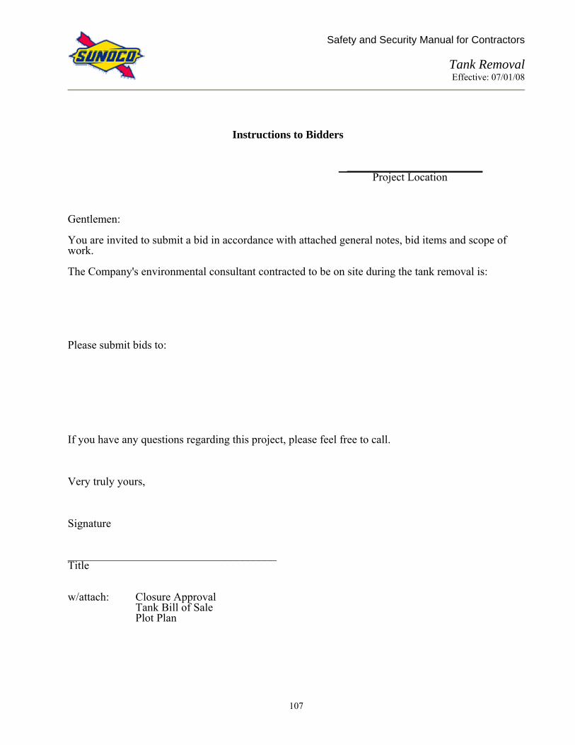
Safety and Security Manual for Contractors
Tank Removal Effective: 07/01/08
107
Instructions to Bidders
________________________ Project Location
Gentlemen: You are invited to submit a bid in accordance with attached general notes, bid items and scope of work. The Company's environmental consultant contracted to be on site during the tank removal is: Please submit bids to: If you have any questions regarding this project, please feel free to call. Very truly yours, Signature _____________________________________ Title w/attach: Closure Approval
Tank Bill of Sale Plot Plan

Safety and Security Manual for Contractors
Tank Removal Effective: 07/01/08
108
Underground Storage Tank Removal General Notes:
- The Compliance Services Department will provide State EPA and the State Fire Marshall a 30 day notification prior to the underground storage tank removal.
- The Risk Management Department will provide a separate environmental consultant
to handle environmental responsibilities and perform all site assessment activities. Contractor will be responsible for coordinating tank removal times with the environmental consultant and assist with sample collections.
- The Terminal Operations Department, as directed by Sales, is responsible for
removing product from underground gasoline storage tanks prior to removal.
- Contractor shall obtain all permits required by federal, state, and local agencies to perform tank removal, disposal and back filling of underground tank systems.
- Contractor responsible for adhering to all safety procedures set by Sunoco.
- Contractor will provide all manifests, bill of sale for tanks, acquired permits, UST
certificate of disposal, and all correspondence within (15) fifteen working days of tank removal. Note: Invoice must include a complete breakdown of work performed, extras must be approved in advance and site Duns number with complete address.
- Contractor to submit rates for material, labor and equipment for out of scope work.
- Contractor responsible for all taxes on materials and labor where applicable.
- Contractor to submit bids within (15) days.
- Dealer responsible for removing fuel oil and waste oil from underground storage
tanks prior to removal.
- All Manifests to be made out to: Sunoco Inc. 1801 Market Street Philadelphia, PA 19103 Attn.: Compliance Services Department
- Contractor to provide photographs to document all critical stage of underground storage tank removal.
- Under no circumstances can waste oil contaminated soil be CO-mingled with any
other contaminated soil pipes on site.

Safety and Security Manual for Contractors
Tank Removal Effective: 07/01/08
109
Bid Items: 1. Remove and dispose of gals. fiberglass, gals. steel underground gasoline storage
tanks and all related piping complete to islands, including conduit and vent piping. 2. Remove and dispose of gals. fiberglass, gals. steel underground waste oil and fuel
tanks and all related piping, including conduit and vent piping. 3. Remove and dispose of service station canopy including all structural steel members and
columns, decking material, conduit and wiring, and column foundations. 4. If applicable, remove and dispose of service station canopy including all structural steel
members and columns, decking material, conduit and wiring, and column foundations. Scope of Work: The contractor shall perform the following work: 1. Cut, remove and dispose of any concrete tank and dispenser mats and asphalt where
necessary. The opening shall be saw cut for neat edges. 2. Prior to excavating tanks, contractor will remove residual product/tank bottoms from all
tanks. Contractor will clean all tanks and remove all residual sludge including any cleaning solutions generated by the cleaning process. Contractor to furnish two (2) 55 gallon drums for subject waste liquids.
3. Prior to excavating tank, contractor will remove residual flammable vapor by standard industry methods. The tank will be checked for residual flammable vapors using an explosimeter prior to removal.
4. Excavate soil a minimum of (2) two feet around all sides and under tanks. If a concrete hold-down pad is under the tank, it shall remain in place. Leave as much soil in ground as possible until it is determined that there is contamination. The environmental consultant will advise on how much soil to be excavated and stock piled. Soil to be stock piled on 6 mil plastic and covered with 6 mil plastic and contaminated as otherwise required by local authorities as contaminated soil for disposal or use as backfill.
5. Contractor shall remove, cut up and dispose of all existing gasoline, fuel oil, waste oil tanks in accordance with all applicable EPA and State regulations.
6. Contractor will remove all piping, conduit and wiring back to breaker box, disconnect and pull wiring, vents, and other attached equipment of underground storage tanks and dispenser islands.
7. Any open excavation in driveways or pedestrian areas must be covered with steel plates.
Excavation in other areas to be protected by standard safety fencing and appropriate warning signs.
8. After the results of laboratory testing and the approval by the Risk Management Department,
the excavated hole will be lined with 6 mil plastic where required, up to grade and filled with approved backfill material. No broken pavement or other large pieces shall be used, or any organic materials. Typical acceptable materials would be pit run gravel, crushed stone, crushed blast furnace slag, sand. Backfill placed in 8" layers and compacted.
9. Contractor to restore all disturbed surfaces to original or better conditions - i.e. asphalt,
concrete or grass, and of equal thickness, unless otherwise instructed.

Safety and Security Manual for Contractors
Tank Removal Effective: 07/01/08
110
RE: Environmental Company Bid Request (Sample) Tank Pull
Duns # Dear Environmental Company: Rep: Fax: Please submit a written proposal for environmental work related to this tank pull as per the following scope of work to be performed at: Duns # Address: City: State Zip Tanks Being Removed: Original Proposed Size Type Quantity Install Date Removal Date
___________ _________ ___________ _________ ___________
Reason for Tank Pull: Known Discharge? Yes/No
Divestment? Yes/No Upgrade Equipment? Yes/No
Scope of Work: Oversee tank pull at above mentioned site. Represent the Company in your determinations as to amount of contamination, soil to be removed, site soil to be taken to (must be on Company’s approved landfill listing), submit closure report to:
Area Risk Management Hydrogeologist Sunoco, Inc. Compliance Services Department
1801 Market St. Philadelphia, Pa 19103
If you are selected to represent the Company in this tank pull, you must include in your closure report the DUNS NUMBER for the site as well as the address of site. If you have any questions, please call us. Sincerely, CC: File

Safety and Security Manual for Contractors
Tank Removal Effective: 07/01/08
111
RE: General Contractor Acceptance
Tank Pull Duns #
(Sample) Dear General Contractor, You have been awarded the contract for the tank pull at the subject site. Please sign contract, keep top copy and return remaining copies as soon as possible. Attached to the contract is a Bill of Sale Form and other required documentation. This form must be filled out and returned to us at time of removal. Upon completion, your invoice must include the following information:
DUNS NUMBER
CONTRACT NUMBER
STREET ADDRESS OF TANK PULL
BILL OF SALE FORM
DATE TANK(S) REMOVED Thank you in advance for your cooperation. Sincerely,

Safety and Security Manual for Contractors
Tank Removal Effective: 07/01/08
112
BILL OF SALE UNDERGROUND STORAGE TANKS FOR AND IN CONSIDERATION of the mutual benefits accruing and expected to accrue hereunder and other valuable consideration, the sufficiency of which is hereby acknowledged, the undersigned Seller hereby bargains, assigns, and sells to the named Contractor, all of the Seller's rights, title and interests in and to the Underground Storage Tanks (UST's) described below, AS IS WHERE IS, WITHOUT WARRANTY OF ANY KIND WHATSOEVER, INCLUDING EXPRESS OR IMPLIED WARRANTY OF MERCHANTABILITY OR FITNESS FOR ANY PURPOSE. Seller warrants it has unencumbered title to the tanks, and that the undersigned representative of Seller is fully authorized to make, execute, and bind Seller to this Bill of Sale. Contractor purchases the tanks with full knowledge that the same have been used for the storage of petroleum products, and that they may contain flammable, explosive, and toxic liquids or vapors, entails certain hazards to personnel working thereon, and results in material which must be handled with care, and which may safely be used only for certain limited purposes. Contractor agrees to destroy said tank(s) upon their removal from the below referenced premises. Contractor agrees to assume full responsibility for compliance with all environmental, health and safety laws, regulations and standards applicable to said tank(s), and shall indemnify and hold Seller harmless from all claims, demands, losses, and actions of any kind, relating to said tanks arising after Contractor takes possession. SELLER: CONTRACTOR ADDRESS: CONTRACTOR TELE #: CONTRACTOR I.D. #: CONTRACTOR I.D. # EXPIRATION: UST QUANTITY/SIZE/PRODUCT: DATE TANKS REMOVED: UST’S LOCATED AT: UST’S DUNS # LOCATION: PURCHASE PRICE: One ($1.00) dollar and other good and valuable consideration.
Date: WITNESS: Contractor:
Date: WITNESS: Seller:
By: Title: Distribution: Maintenance Department
Fixed Assets Department Compliance Services Department

Safety and Security Manual for Contractors
Contractor Safety Performance Selection Criteria & Enforcement Actions Effective: 07/01/08
113
CONTRACTOR SAFETY PERFORMANCE SELECTION CRITERIA & ENFORCEMENT ACTIONS 1.0 PURPOSE:
This procedure provides the guidelines for Contractor safety performance selection criteria and enforcement actions.
2.0 SCOPE:
This policy covers all Branded Marketing-Technical Services Contractor and Sub-Contractors that will have personnel working on Sunoco Marketing Retail sites.
3.0 RESPONSIBILITY:
The Retail Engineering, Construction, Environmental Services, and Maintenance Management Team are responsible for management of this procedure. Establishing that contractors or subcontractors will not be required to execute work on Sunoco Marketing Retail sites, and therefore not covered by this section’s requirements, will be the responsibility of the Technical Services Manager requesting the contract with the contractor. Sunoco Contractors are responsible for evaluating and managing the safety performance of their personnel and subcontractors in a manner consistent with Sunoco's goal of providing a safe environment at all Sunoco facilities.
Contractors are responsible for reviewing the EMR and OSHA recordable injury (or equivalent) data for their subcontractors, developing, and implementing procedures for the evaluation and approval of subcontractor Safety Performance consistent with Sunoco's criteria.
Contractors will provide, at Sunoco’s request, the EMR and justification for using their subcontractors.
4.0 REFERENCES: (none) 5.0 CONTRACTOR SAFETY PERFORMANCE SELECTION CRITERIA 5.1 Experience Modification Rate (EMR) EMR Value (most current value) Requirements for use EMR values up to 1.0 … can be selected for use following review and
approval by the Technical Services Personnel (Maintenance Superintendents, Senior

Safety and Security Manual for Contractors
Contractor Safety Performance Selection Criteria & Enforcement Actions Effective: 07/01/08
114
Construction Engineers, Senior Environmental Managers, Senior Retail Engineers) responsible for contractor selection.
EMR value >1.0 but < than or equal to 1.1 Note: OSHA TRIR equal to or < than twice the Technical Services TRIR Goal for contractors … … can be selected for use following review and
approval by the Technical Services Personnel (Maintenance Superintendents, Senior Construction Engineers, Senior Environmental Managers, Senior Retail Engineers) responsible for contractor selection. Such review will take into account senior management’s goal to only utilize contractors’ engaging in safe work practices.
EMR value > 1.1 but < than or equal to 1.2 … can be selected for use following review and
approval by the Manager of Retail Engineering, Construction, Maintenance, or Environmental Services. Such review will take into account senior management’s goal to only utilize contractors’ engaging in safe work practices.
. EMR value > 1.2 …requires the submission of a Safety
Performance Improvement Plan by the contractor for review/acceptance by the Technical Services Management Team.
EMR value > 1.3 …requires the submission of a Safety
Performance Improvement Plan by the contractor for review/acceptance by a Senior VP of Sunoco.
5.2 Safety Performance Improvement Plan
- The minimum requirements for the Safety Performance Improvement Plan are listed here for your reference.
- An explanation of the EMR level, or the lack of EMR data, including the loss run reports for the last three years and projection from the insurer of what the EMR will most likely be at the next renewal. This should be compared with OSHA records where available.
- A Continuous Improvement Process including the following elements.
• Results of injury incident investigations and root cause analysis.

Safety and Security Manual for Contractors
Contractor Safety Performance Selection Criteria & Enforcement Actions Effective: 07/01/08
115
• Corrective actions identified with documentation of execution.
• Performance criteria to be used to evaluate, measure improvement (EMR, OSHA TRIR, or other equivalent measures).
• Quarterly Safety Performance reporting to Sunoco. (including updates of all of the above)
6.0 Contractor Safety Program - Enforcement Actions
6.1 Failure to provide information required by the Sunoco Contractor Qualification and Safety Questionnaire or comply with any of the requirements of the Contractor Safety and Security Manual for Contractors Working in Service Stations and Related Retail Outlets will subject the contractor(s) to any or all of the Enforcement Actions listed below. The enforcement actions to be taken will be determined and carried out by:
• the Sunoco Technical Services Personnel responsible for the managing the work,
• Technical Services Materials Management,
• the Technical Services HES Project Manager, and
• the Technical Services Management Team as required.
6.2 Enforcement actions:
• Unacceptable Safety Performance Contracts will not be approved or will have their term limited to one year for contractors with high EMR and/or multiple OSHA recordable injuries. Contract renewal beyond that term will be based on contractor safety performance improvement.
• Violations of Sunoco Safety and Security Requirements
Level 1 Enforcement – Corrective Actions required of the Contractor to meet the requirements of Sunoco’s Safety and Security Manual. Identified by Job Site Safety Audits and Incident Investigations. Enforced by the Technical Services Personnel involved.
Level 2 Enforcement – Suspension of work and/or invoice payments.
Whenever information, corrective action, or follow-up action required is not provided/executed in a timely manner.
Level 3 Enforcement - Retraining of Contractor/Sub-Contractor Personnel at the contractors expense. Response to a failure to show improvement in safety performance between
inspections and/or repeated violations of the same type.

Safety and Security Manual for Contractors
Contractor Safety Performance Selection Criteria & Enforcement Actions Effective: 07/01/08
116
May involve actions ranging from a documented tailgate safety meeting up to offsite training of contractor personnel by a Certified Safety Professional or other acceptable resource at the contractors expense.
Level 4 Enforcement - Removal from the acceptable contractor/bidder/sub-contractor lists. Based on the severity of the violation, the number of violations, performance
that fails to improve, or the Suspension of Work/Invoice payments does not result in acceptable performance by the contractor.
Restoration to the acceptable contractor/bidder/sub-contractor lists requires review of the corrective actions taken by the contractor by the Technical Services Management Team.
Level 5 Enforcement - Termination of Contract Last Step when all else fails and/or flagrant violations of Sunoco requirements
occur. The Issuance of a new Contract (under the same or a new vendor ID) requires
the written approval of, Materials Management, Company Operations Management, Dealer Operations Management, all Technical Services Managers, and the Director of Technical Services.
• Contractor Failure to report Incidents (Personal injury and/or Property
Damage) involving Contractor Personnel that occur at Sunoco Sites according to the requirements of the Contractor Safety and Security Manual.
Minimum Enforcement Action: Contract Probation Period of one year
During Probation Period Contractor is required to provide monthly/written documentation of all insurance claim/OSHA injury information to the Sunoco Technical Services Personnel assigned to review the contractor’s performance.
Probation Compliance Failure will subject the contractor to Level 3 - 5 Enforcement actions noted in ‘Category 2 Performance Review’ above.
Enforcement Action Option: Termination of Contract

Safety and Security Manual for Contractors
Bucket Truck (Aerial Lift) Safety Effective: 07/01/08
117
BUCKET TRUCK (AERIAL LIFT) SAFETY 1.0 PURPOSE:
This procedure describes the actions to be taken prior to and during operation of a bucket truck (aerial lift). It is for use by employees and contractors.
2.0 SCOPE:
This policy covers all Contractor and Sub-Contractor employees working at a Sunoco location.
3.0 RESPONSIBILITY:
The Retail Engineering, Construction and Maintenance Management Team is responsible for the management and implementation of this procedure. Maintenance technicians and contractors are responsible for the knowledge of, and adherence to these procedures.
4.0 REFERENCES:
4.1 29 CFR 1926 Subpart O - Motor Vehicles, Mechanized Equipment, Marine Operations
4.2 29 CFR 1910 Subpart F - Powered Platforms, Manlifts, and Vehicle Mounted Work
Platforms 5.0 PROCEDURE
5.1 Only personnel trained in the operation of the Aerial Lift shall be permitted to operate the Aerial Lift.
5.1.1 The training and instruction shall only be performed by competent and
qualified personnel and as a minimum will include:
• A thorough and complete review, including a hands-on discussion, covering the Aerial Truck and its components.
• A discussion on the different handling and driving characteristics of the Aerial Truck, also discussing any additional Department of Transportation Regulations required because of a higher Gross Vehicle Weight
• A discussion on the proper entry and exit from the bucket and rear platform.
• A discussion about the proper operation of the Aerial Lift, covering the function of each control and the operating and safety regulations concerning the Aerial Lift operation.

Safety and Security Manual for Contractors
Bucket Truck (Aerial Lift) Safety Effective: 07/01/08
118
• A hands-on operating session where the trainee operates the Aerial Lift, and performs the operation of each control to the instructor's satisfaction.
• A familiarization of the operation section in the Aerial Lift Manual assigned to each vehicle.
• Periodic follow-up training shall include observance of the operator performing maintenance operations with the Aerial Lift.
• Any new or different style aerial lifts will require initial training for everyone.
5.2 The complete unit, including the Aerial Lift, shall be maintained in a safe and proper
operating condition by the operator.
5.2.1 The bucket, boom, power supplies, operating and safety controls and other devices must be maintained.
5.2.2 The truck tires should be properly inflated, and the brakes should be in proper
adjustment.
5.3. The job site or parking location should be firm pavement, as level as possible and free from overhead obstructions.
5.3.1 The Aerial device does not provide protection from contact with or proximity
to, an electrically charged conductor. When operating the Aerial Lift proximate to, under, over, by or near electric power lines, maintain a minimum clearance of at least 10 feet between electric power lines and any part of the aerial device.
5.3.2 Never operate Aerial Lift with the truck parked on a slope exceeding five (5) degrees.
5.3.3 Avoid locations with soft, muddy, rocky and uneven terrain, steep grades and
locations having overhead obstructions.
5.3.4 Park the truck at the job site in the best manner possible for stability.
5.3.5 Position the truck so all the work can be performed without having to reposition the truck.
5.4 Once positioned at the job site:
5.4.1 Set the truck parking brake.
Safety and Security Manual for Contractors
Bucket Truck (Aerial Lift) Safety Effective: 07/01/08
119
5.4.2 Install the transmission in the park position. For trucks with standard transmissions, put it in neutral.
5.4.3 Install two (2) chock blocks under rear wheels.
5.4.4 Determine the total working area of the Aerial Lift, and by using traffic cones
block off an area at least 6 feet beyond the farthest point directly below the Aerial Lift.
5.5 Once the job site is secured:
5.5.1 Start the engine, let idle.
5.5.2 Turn on the Aerial Lift operating switches, (engine stop-start, Hydraulic
pump, emergency power, speed control).
5.5.3 Enter the bucket from the rear platform, utilizing the grab handle and exercising caution to be sure of adequate footing ( ice, snow, etc.).
5.5.4 Do not operate the Aerial Lift without the proper training.
5.6 Bucket Operation
5.6.1 Safety harness/belt and lanyard must be worn when operating the Aerial Lift.
• The safety belt must have a minimum width of 3 inches and be equipped with a self closing fastening device equipped with a locking device to prevent accidental opening of the fastening device.
• The lanyard should have a maximum length of 5 feet.
5.6.2 Never belt onto an adjacent pole or other structure when working from the Aerial Lift.
5.6.3 Do not exceed the rated capacity of the Aerial Lift.
5.6.4 Do not allow unauthorized persons on the ground to touch working units.
5.6.5 Do not enter or leave the bucket by walking or climbing the boom.
5.6.6 Transfer from the bucket may only be made to a stationary platform, i.e.
canopy deck or roof. The bucket must be extended over the platform by at least 2 feet.
5.6.7 Do not use ladders or steps or any other arrangement for working outside the
bucket.

Safety and Security Manual for Contractors
Bucket Truck (Aerial Lift) Safety Effective: 07/01/08
120
5.6.8 Do not sit or stand on the edge of the bucket.
5.6.9 Always look in the direction you are moving.
5.6.10 Avoid maximum outward reach position on downhill side when unit is located
on a sloping surface.
5.6.11 Do not let bucket descend on, or strike a fixed object.
5.6.12 Always be sure, any tools or parts carried in the bucket are secure.
5.6.13 When using the shore power source for the bucket, be sure the power cable to the truck is secure, and that the power cable and any power tools being used have a grounded circuit.
5.6.14 Safety and protective equipment must be used when required.
5.6.15 The Aerial Lift Truck may not be moved when the boom is elevated in a
working position with personnel in the bucket.
5.7. When the Aerial Lift is completed:
5.7.1 Make sure the boom is properly stored in the boom support.
5.7.2 Shut off the bucket operating switches.
5.7.3 Make sure the bucket is free of personnel, loose tools and materials before traveling on the road.
5.7.4 Make sure the vehicle operator is aware of the overall height of the Aerial Lift
Truck for proper clearance, signs, low bridges, etc.
5.8 The handling characteristic of a truck equipped with an Aerial Lift may be different because of the higher center of gravity. Extra caution should always be taken by the operator.
5.9 If any abnormal operation is detected, the condition must be corrected before the
Aerial Lift is operated.

Safety and Security Manual for Contractors
Dispenser Transportation and Disposal Effective: 07/01/08
121
DISPENSER TRANSPORTATION AND DISPOSAL 1.0 PURPOSE: This procedure describes the actions to be taken when scrapping a dispenser. It is for use by
anyone transporting and disposing of a used dispenser. 2.0 SCOPE:
This policy covers all Contractor and Sub-Contractor employees who perform activities relating to dispenser transportation and disposal.
3.0 RESPONSIBILITY:
Retail Engineering, Construction and Maintenance Management Team is responsible for management of this procedure. The individual moving or scrapping a dispenser is responsible for knowledge of, and adherence to, this procedure. This procedure is included in the “Safety and Security Manual for Contractors”.
4.0 REFERENCES (not applicable): 5.0 PROCEDURE:
5.1 Safe Operating Procedures for Dismantling Dispensers to Remove Gasoline
5.1.1 This procedure is the responsibility of anyone removing gasoline from dispensers to make them ready for transportation and disposal. The primary job hazard is overexposure to gasoline vapors and contact with free product. Required protective equipment includes Nitrile Gloves, Chemical Goggles or Face Shield, and Fire Extinguisher.
5.1.2 Other recommended equipment includes Forklift, Explosion Proof Fan,
Gasoline Collection Drum, Funnel, Spill Pads, Hazardous Waste Drum, and Rotating Work Platform with Work Area Pan. The purpose is to minimize exposure to gasoline vapors.
5.2 When removing gasoline from old dispensers in preparation for transportation to an
approved stocking facility or for disposal as scrap, the following instructions must be followed:
5.2.1 Remove all dispenser doors in order to allow for ventilation. 5.2.2 Place flat tray or collection pan under the dispenser. Line the bottom of the
collection pan/tray with spill pads. 5.2.3 Place the dispenser on the collection tray in a position so that the majority of
work can be performed up-wind. 5.2.4 Put on Nitrile gloves and goggles or face shield. Position fire extinguisher
nearby.

Safety and Security Manual for Contractors
Dispenser Transportation and Disposal Effective: 07/01/08
122
5.2.5 Position the explosion proof fan, if needed, so that any vapors blow away from the Technician. The fan should ideally be placed at a 45 degree angle from the dispenser when possible. Turn the fan on.
5.2.5 Remove visible caps or plugs from the dispenser to allow gasoline to drain
easily. 5.2.6 Place a small gasoline collection pan under the filter. 5.2.7 Remove filter(s) and pour gasoline into a remote collection can with a funnel.
Leave the filter upside down in the funnel to drain all of the gasoline. Dispose of filter in the hazardous waste drum.
5.2.8 Remove copper tubing and drain into the small collection pan. 5.2.9 Remove/disassemble the meter and drain the gasoline into the remote
collection can with a funnel. 5.2.10 Remove strainer and catch the gasoline in the small collection pan.
Immediately empty the collection pan into the remote can/funnel. 5.2.11 General Precautions
• Always turn dispenser so that the Technician can be positioned between
the fan and the work area (up-wind). • Miscellaneous tubing and parts should be placed in an open drum or
dumpster at a remote location so that they can continue to “air out”. • Remove and replace pan spill pads as necessary when they are
contaminated with gasoline. • When positioning the dispenser, if possible, raise the dispenser to a
comfortable working level to reduce excessive bending of the back. • All work will be performed either outside or in a well-ventilated area. No
work will be performed in a closed building. • All work should be performed with the intent to reduce exposure to
gasoline vapors and free product. Take the time to reposition the dispenser to work in the up-wind area.
• All fans, etc. must be explosion-proof. • Never operate a fork lift unless you have been trained and certified to do
so

Safety and Security Manual for Contractors
Pre-Job Contractor Safety Checklist Effective: 07/01/08
123
PRE-JOB CONTRACTOR SAFETY CHECKLIST Date: _______________ Project: _______________________Contractor Name:___________________
Owner’s Representative Name: ______________________________________ The following Procedures must be discussed as part of the Pre-Job Meeting with "YES" signifying the contractor is fully aware of the procedure and responsibilities and will communicate the Procedures to everyone involved in the work (employees, sub-contractors, vendors, etc.) and ensure compliance. Work will not be allowed to progress in any area marked "N/A" or " NO." Procedure Yes No N/A Comments Key Contact List Safety Requirements and Equipment
Emergency Procedures Area Restrictions On-Truck Safety Equipment Personal Protective Equipment Safety Plan Pre-Job Site Safety Meeting Emergency Posting First Aid Equipment Flashlights Lighting the Work Area Housekeeping (29 CFR 1926.25) Compressed Gas Cylinders Scaffolds
Accident Investigations Barrier Protection Blocking Driveways Color Code Product I.D. System Confined Space Entry Crane, Rigging & Hoisting Safety D.O.T. Regulations – Contractors Electrical Safety Emergency Shut-Off Valve Operation Excavations Flexible Connector Removal Filter Changing Fire Protection Forklift Safety Hazardous Waste Manifests Ladder Safety Lifting & Carrying Lock/Tagout Hazard Communication/MSDS

Safety and Security Manual for Contractors
Pre-Job Contractor Safety Checklist Effective: 07/01/08
124
Safety Meetings Safety Procedures for Interior Renovations Security – Contractor Spill Reporting & Response Tank Removal Contractor Safety Performance Selection Criteria & Enforcement Actions
Bucket Truck (Aerial Lift) Safety Dispenser Transportation and Disposal

Safety and Security Manual for Contractors
PPE Hazard Assessment Form Effective: 07/01/08
125
PPE HAZARD ASSESSMENT FORM Job Task: Date: Project Location: Assessed By: Job Title:
Potential Hazards: (Check all that apply to either existing conditions or are a result of site operations)
( ) Rotating Machinery ( ) Projectiles ( ) Confined Space ( ) Heat Stress ( ) Physical Exertion ( ) Biological ( ) Cold Stress ( ) Noise (>90 dBA) ( ) Electrical (utilities) ( ) Heavy Equipment ( ) Vehicle Traffic ( ) Chemical Exposure ( ) Intrusive Activity ( ) Fire/Explosion ( ) Other: Slips, trips, & falls ( ) Trench/excavation collapse ( ) Uneven Terrain ( ) Flammable materials ( ) Other: ( ) Contact with contaminated soil or water
Control or Protective Measures: (Check all that apply)
( ) Tailgate Meetings ( ) PPE ( ) Safe Work Practices ( ) Employee or Operator Training ( ) Site Control ( ) Decontamination ( ) Engineering Controls: ( ) Other: Install caution-tape/barriers around operation,
establish sufficient work space and minimize access. INITIAL LEVEL OF PERSONAL PROTECTIVE EQUIPMENT FOR ASSIGNED TASK: PPE has been assigned for this work task per the potential for exposure. PPE requirements are outlined below. PPE may be upgraded or downgraded depending on monitoring data, site conditions, or as determined by qualified personnel. Respirator: ( ) SCBA, Airline ( ) Fullface APR Resp. ( ) 1/2 Face APR Resp. ( ) N95 Dust Mask ( ) OV/AG/HEPA Cart. ( ) Other Cart.
Protective clothing: ( ) Encapsulating Suit ( ) Tyvek ( ) Poly Coated Tyvek ( ) Saranex ( ) Splash Suit ( ) Other:
Head/eye/ear: ( ) Hard Hat ( ) Safety Glasses ( ) Goggles ( ) Welding Shield ( ) Splash Shield ( ) Ear Plugs/Muffs ( ) Other:
Gloves: ( ) Nitrile ( ) Neoprene ( ) PVC - Use with Petroleum Products ( ) Vinyl ( ) Leather ( ) Cotton ( ) Other
Footwear: ( ) Leather work boots ( ) Safety-toed Leather ( ) Chemical Overboots ( ) Safety-toed Rubber ( ) Other:
Other PPE: ( )
( )
Signature of the person that performed the assessment Date of Assessment

Safety and Security Manual for Contractors
Project Safety Plan Effective: 07/01/08
126
PROJECT SAFETY PLAN Project Information Project number: Project Start Date: Site Name & Location: Project Manager: Client Company Name: Client Representative Name: Client’s Telephone #: Site Telephone #: Project Description (Describe the project scope, objectives, and duration of onsite work) Key Project Personnel (List names, titles, and responsibilities for the project) Safety and Accident Prevention Plans (Describe procedures, safe work practices, and equipment required to protect employees and subcontractors from hazards posed by site activities. Topics to consider: Confined Space Entry, Hazard Communication, Excavation Safety, Fire Protection and Prevention, Electrical Safety, Lockout/Tagout, Crane & Rigging Safety, Personal Protective Equipment, Housekeeping, Ladder Safety, Safety Meetings, etc…) Hazard Assessments (Describe procedures on how work activities will be assessed for potential hazards including identifying personal protective equipment requirements.) Emergency & Contingency Programs (Describe emergency procedures for medical, fire, chemical, severe weather, etc., incidents.) Training and Communication (Describe what training employees will receive, when refresher training is needed, and how information will be communicated to the employees- ex. safety meetings)