safety in control systems - according to en iso 13849-1 abb
TRANSCRIPT

Safety in control systemsaccording to EN ISO 13849-1Machine Safety - Jokab Safety products

2 | Safety in control systems according to EN ISO 13849-1
New standards for safety in control systems
Building a protection system that works in practice and provides sufficient safety requires expertise in several areas. The design of the safety functions in the protection system in order to ensure they provide sufficient reliability is a key ingredient. As help for this there is, for example, the EN ISO 13849-1 standard. With this document we aim to provide an introduction to the standard and its application in conjunction with our products.
Introducing the new standardThe generation change for standards on safety in control systems introduces new concepts and calculations for machine builders and machine users. The EN 954-1 standard (categories) is being phased out and replaced by EN ISO 13849-1 (PL, Performance Level) and EN 62061 (SIL, Safety Integrity Level). Although the deadline for using EN 954-1 is set to 31/12/2011, it is beneficial to start applying the new standards as soon as possible as many new standards no longer refer to EN 954-1.
PL or SIL? What should I use?The standard you should use depends on the choice of technology, experience and customer requirements.
Choice of technology• PL (Performance Level) is a technology-neutral concept
that can be used for electrical, mechanical, pneumatic and hydraulic safety solutions.
• SIL (Safety Integrity Level) can, however, only be used for electrical, electronic or programmable safety solutions.
ExperienceEN ISO 13849-1 uses categories from EN 954-1 for defining the system structure, and therefore the step to the new calculations is not so great if you have previous experience of the categories. EN 62061 defines the structures slightly differently.
Customer requirements If the customer comes from an industry that is accustomed to using SIL (e.g. the process industry), requirements can also include safety functions for machine safety being SIL rated.
We notice that most of our customers prefer PL as it is technology-neutral and that they can use their previous knowledge in the categories. In this document we show some examples of how to build safety solutions in accordance with EN ISO 13849-1 and calculate the reliability of the safety functions to be used for a particular machine. The examples in this document are simplified in order to provide an understanding of the principles. The values used in the examples can change.
What is PL (Performance Level)?PL is a measure of the reliability of a safety function. PL is divided into five levels (a-e). PL e gives the best reliability and is equivalent to that required at the highest level of risk.
To calculate which level the PL system achieves you need to know the following:• The system’s structure (categories B, 1-4)• The Mean Time To dangerous Failure of the component
(MTTFd)• The system’s Diagnostic Coverage (DC)
You will also need to:• protect the system against a failure that knocks out both
channels (CCF)• protect the system from systematic errors built into the
design• follow certain rules to ensure software can be developed
and validated in the right way
The five PL-levels (a-e) correspond to certain ranges of PFHD-values (probability of dangerous failure per hour). These indicate how likely it is that a dangerous failure could occur over a period of one hour. In the calculation, it is beneficial to use PFHD-values directly as the PL is a simplification that does not provide equally accurate results.
What is the easiest way of complying with the standard?1. Use pre-calculated componentsAs far as it is possible, use the components with pre-calculated PL and PFHD-values. You then minimise the number of calculations to be performed. All ABB Jokab Safety products have pre-calculated PFHD-values.
2. Use the calculation toolWith the freeware application SISTEMA (see page 16) you avoid making calculations by hand. You also get help to structure your safety solutions and provide the necessary documentation.
3. Use Pluto or Vital Use the Pluto safety PLC or Vital safety controller. Not only is it easier to make calculations, but above all it is easier to ensure a higher level of safety.

Safety in control systems according to EN ISO 13849-1 | 3
We develop innovative products and solutions for machine safetyWe make it easy to build protection systems. Developing innovative products and solutions for machine safety has been our business concept since the company started in Sweden in 1988. Our vision is to be “Your partner for machine safety - globally and locally”.
Many companies, both in Sweden and abroad, have discovered how much easier it is to build safety and protection systems using products and guidance from us.The goal of our development is to ensure a high safety level (PL e). This is to help our customers create safe workplaces, regardless of who is assessing the risk level.
ExperienceWe have extensive experience in the practical application of regulations and standards from both authorities and manufacturing operations. We represent Sweden in the standards body for machinery safety and we work daily with the practical application of safety requirements in combination with production requirements. You can utilise our expertise for training and advice about the new Machinery Directive, risk analysis and safety in control systems.
SystemsWe supply everything from a safety solution for a complete protection system installed on individual machines or entire production lines. We combine production requirements with safety requirements for production-friendly solutions.
ProductsWe have a complete range of safety components that make it easy to build protection systems. We develop these innovative products continuously, often in collaboration with our customers.
The description and example in this document show how the product works and can be used. This does not mean that it satisfies the requirements for all types of machines and processes. The purchaser/user is responsible for the product being installed and used in line with applicable regulations and standards. We reserve the right to make changes to the product and product sheet without prior notice.
Terms as specified in EN ISO 13849-1
T10d Mean time until 10 % of the components have a dangerous failure (Component operating time is restricted to T10d)
CCF Common Cause Failure
DC Diagnostic Coverage Divided into Low, Medium and High
PFHD Probability of Dangerous Failure per Hour (Average probability of dangerous failure per hour)
PL Performance Level Divided into a to e
PLr Required Performance Level (The required performance level for a particular
safety function)
MTTFd Mean Time To Dangerous Failure is divided into Low, Medium and High
B10d Number of cycles until 10 % of the components have a dangerous failure (for pneumatic and electromechanical components)
Contents:
Page 2 Introduction
Page 4 Work method according to EN ISO 13849-1
Page 8 Case study using RT9
Page 10 Case study using Vital
Page 12 Case study using Pluto
Page 14 What defines a safety function?
Page 16 SISTEMA
Page 17 Safety relay, Vital or Pluto?

4 | Safety in control systems according to EN ISO 13849-1
Risk assessment and risk minimisationAccording to the Machinery Directive, the machine builder (anyone who builds or modifies a machine) is required to perform a risk assessment for the machine design and also include an assessment of all the work operations that need to be performed. The EN ISO 12100 standard (combination of EN ISO 14121-1 and EN ISO 12100-1/-2) stipulates the requirements for the risk assessment of a machine. It is this that EN ISO 13849-1 is based on, and a completed risk assessment is a prerequisite for being able to work with the standard.
Step 1 – Risk assessmentA risk assessment begins with determining the scope of the machine. This includes the space that the machine and its operators need for all of its intended applications, and all operational stages throughout the machine’s life cycle.
All risk sources must then be identified for all work operations throughout the machine’s life cycle.
A risk estimation is made for each risk source, i.e. indication of the degree of risk. According to EN ISO 13849-1 the risk is estimated using three factors: injury severity (S, severity), frequency
of exposure to the risk (F, frequency) and the possibility you have of avoiding or limiting the injury (P, possibility). For each factor two options are given. Where the boundary between the two options lies is not specified in the standard, but the following are common interpretations:
S1 bruises, abrasions, puncture wounds and minor crushing injuries
S2 skeletal injuries, amputations and death
F1 less frequently than every two weeks
F2 more often than every two weeks
P1 slow machine movements, plenty of space, low power
P2 quick machine movements, crowded, high power
By setting S, F and P for the risk, you will get the PLr Performance Level (required) that is necessary for the risk source.
Finally, the risk assessment includes a risk evaluation where you determine if the risk needs to be reduced or if sufficient safety is ensured.
Has the risk been adequately
reduced?
Is the measure dependent on the control system?
Start
End
Are new risks generated?
Yes
No
Yes
Yes
No
No
Ris
k as
sess
men
t
Ris
k an
alys
is
Step 1
Step 2
Determine the system's scope(space, usage, time, environment)
Identify risk sources(all work operations during the life cycle)
Estimate the risk(determine PLr with S, F and P)
Evaluate the risk(is action required?)
Working method as specified in EN ISO 13849-1
Reduce the risk(pre-empt, use protection,
information)

Safety in control systems according to EN ISO 13849-1 | 5
a
b
c
d
e
PLr
)�
)�
)�
)�
6�
6�
3�
3�
3�
3�
3�
3�
3�
3�
Risk estimation
To calculate the performance level required (PLr).
S Severity of injuryS1 slight (normally reversible injury)S2 serious (normally irreversible injury or death)
F Frequency and/or exposure to hazardF1 seldom to less often and/or exposure time is shortF2 frequent to continuous and/or exposure time is long
P Possibility of avoiding hazard or limiting harmP1 possible under specific conditionsP2 scarcely possible
Step 3 - Design and calculate the safety functionsTo begin with you need to identify the safety functions on the machine. (Examples of safety functions are emergency stop and monitoring of gate.)
For each safety function, a PLr should be established (which has often already been made in the risk assessment). The solution for the safety function is then designed and implemented. Once the design is complete, you can calculate the PL the safety function achieves. Check that the calculated PL is at least as high as PLr and then validate the system as per the validation plan. The validation checks that the specification of the system is carried out correctly and that the design complies with the specification.You will also need to verify that the requirements that are not included in the calculation of the PL are satisfied, that is, ensure that the software is properly developed and validated, and that you have taken adequate steps to protect the technical solution from systematic errors.
Step 2 – Reduce the riskIf you determine that risk reduction is required, you must comply with the priority in the Machinery Directive in the selection of measures:
1. Avoid the risk already at the design stage. (For example, reduce power, avoid interference in the danger zone.)
2. Use protection and/or safety devices. (For example, fences, light grids or control devices.)
3. Provide information about how the machine can be used safely. (For example, in manuals and on signs.)
If risk reduction is performed using safety devices, the control system that monitors these needs to be designed as specified in EN ISO 13849-1.
No
Yes
Yes
Step 3
low risk
high risk
Verify thatPL ≥ PLr
Identify the safety functions
Determine PLr
Design and implement the solution for the safety function
Calculate PL
ValidateHave other
require ments been met?
Are
all
safe
ty f
unct
ions
exe
cute
d?
No

6 | Safety in control systems according to EN ISO 13849-1
PFHD PL
10-4
a10-5
b3x10-6
c10-6
d10-7
e10-8
PL calculation in Step 3 When you calculate the PL for a safety function, it is easiest to split it into separate, well defined blocks (also called subsystems). It is often logical to make the breakdown according to input, logic and output (e.g. switch - safety relay - contactors), but there may be more than three blocks depending on the connection and the number of components used (an expansion relay could for example create an additional logic block).
For each block, you calculate a PL or PFHD-value. It is easiest if you obtain these values from the component manufacturer, so you do not have to calculate yourself.
The relationship between categories, the DCavg, MTTFd for each channel and PL. The table also shows the PFHD-range that corresponds to each PL.
The manufacturer of switches, sensors and logic devices often have PL and PFHD-values for their components, but for output devices (such as contactors and valves) you do not usually specify a value as it depends on how often the component will be used. You can then either calculate yourself according to EN ISO 13849-1 or use the pre-calculated example solutions such as those from ABB Jokab Safety.
To calculate PL or PFHD for a block, you need to know its category, DC and MTTFd. In addition, you need to protect yourself against systematic errors and ensure that an error does not knock out both channels, and generate and validate any software used correctly. The following text gives a brief explanation of what to do.
Safety function (SF)
+ + PFHD, Input
Input
PL/PFHD
PFHD, Logic
Logic
PL/PFHD
PFHD, Output
Output
PL/PFHD
PFHD, Total =
DCnone
DCnone
DClow
DCmedium
DClow
DCmedium
DChigh
Cat. B Cat. 1 Cat. 2 Cat. 3 Cat. 4
MTTFdlow
MTTFdmedium
MTTFdhigh

Safety in control systems according to EN ISO 13849-1 | 7
Category The structure for the component(s) in the block is assessed to determine the category (B, 1-4) it corresponds to. For category 4, for example, individual failures do not result in any loss of the safety function.
In order to achieve category 4 with contactors, you need to have two channels - i.e., two contactors - that can cut the power to the machine individually. The contactors need to be monitored by connecting opening contacts to a test input on, for example a safety relay. For monitoring of this type to work, the contactors need to have contacts with positive opening operation.
Diagnostic Coverage (DC)A simple method to determine DC is explained in Appendix E in EN ISO 13849-1. It lists various measures and what they correspond to in terms of DC. For example, DC=99 % (which corresponds to DC high) is achieved for a pair of contactors by monitoring the contactors with the logic device.
Mean Time To dangerous Failure (MTTFd)The MTTFd-value should primarily come from the manufacturer. If the manufacturer cannot provide values, they are given from tables in EN ISO 13849-1 or you have to calculate MTTFd using the B10d-value, (average number of cycles until 10 % of the components have a dangerous
If you use a safety PLC for implementing safety functions, this places requirements on how the software is developed and validated. To avoid error conditions, the software should be readable, understandable and be possible to test and maintain.
A software specification must be prepared to ensure that you can check the functionality of the program. It is also important to divide the program into modules that can be tested individually. Paragraph 4.6 and Appendix J of EN ISO 13849-1 specify requirements for safety related software.
The following are examples of requirements for software from EN ISO 13849-1:• A development life cycle must be produced with
validation measures that indicate how and when the program should be validated, for example, following a change.
• The specification and design must be documented.• Function tests must be performed.• Validated functional blocks must be used whenever
possible.• Data and control flow are to be described using, for
example, a condition diagram or software flow chart.
Requirements for safety-related software
Calculation of the average number of cycles is as follows:
dop • hop • 3600
tcycle
nop =
B10d
0,1 • nopMTTFd =
nop = Number of cycles per yeardop = Operation days per year hop = Operation hours per daytcycle = Cycle time (seconds)
failure). To calculate the MTTFd, you also need to know the average number of cycles per year that the component will execute.With a B10d=2·106 this gives a MTTFd=1,141 year which corresponds to MTTFd=high.
Note that when you calculate MTTFd you have to calculate according to the total number of cycles the component will be working. A typical example of this is the contactors that frequently work for several safety functions simultaneously. This means that you must add the number of estimated cycles per year from all the safety functions that use the contactors.When MTTFd is calculated from a B10d-value, also consider that if the MTTFd-value is less than 200 years, the component needs to be replaced after 10 % of the MTTFd-value (due to the T10d-value). That is, a component with MTTFd = 160 years needs to be replaced after 16 years in order for the conditions for achieving PL to continue to be valid. This is because EN ISO 13849-1 is based on a “mission time” of 20 years.
Common Cause Failure (CCF)In Appendix F of EN ISO 13849-1 there is a table of actions to be taken to protect against CCF, to ensure a failure does not knock out both channels.
Systematic errorsAppendix G of EN ISO 13849-1 describes a range of actions that need to be taken to protect against incorporating faults into your design.
PL for safety functionsPL is given in the table on the facing page. If you want to use an exact PFHD-value instead, this can be produced using a table in Appendix K in EN ISO 13849-1.
Once you have produced the PL for each block, you can generate a total PL for the safety function in Table 11 of EN ISO 13849-1. This gives a rough estimate of the PL. If you have calculated PFHD for each block instead, you can get a total of PFHD for the safety function by adding together all the values of the blocks. The safety function’s total PFHD corresponds to a particular PL in Table 3 of EN ISO 13849-1.
Example: dop= 365 days, hop= 24 hours and tcycle= 1,800 seconds (2 times/hour) which gives nop= 17,520 cycles.
Where

8 | Safety in control systems according to EN ISO 13849-1
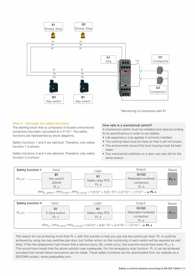
Step 1 – Risk assessmentFood to be packaged is loaded into the cell manually through the rear door. A batch is prepared for the packing conveyor in the infeed hopper. The cell is reset and restarted. The packaging machine with conveyor belt only operates hen both doors are closed and when the protection system has been reset.
In the risk assessment it was established that the machine is to be operated in three shifts (8 hours per shift) 365 days a year. It is assumed that operational disturbances were resolved in less than one minute in the danger zone. This can be carried out two times per hour (F2). Unexpected start-ups are not deemed to cause serious injury but rather minor healable injuries (S1). The operator is deemed not to have the possibility of avoiding injury as the machine moves quickly (P2).
The number of cycles for the safety function = 365 days/ year · (3·8) hours/day · 2 cycles/hour = 17,520 cycles/year
The assessment for the safety function required for access to the machine is PLr= c (S1, F2, P2). In addition to this safety function, an emergency stop function is needed. This is also assessed as PLr=c.
Example 1Safety system using RT9
Assessment of the PLr necessary for the safety function with interlocked door for this example.
NOTE: The assessment needs to be made for each safety function.
a
b
c
d
e
)�
)�
)�
)�
6�
6�
3�
3�
3�
3�
3�
3�
3�
3�
PLrlow risk
high risk
Protection layout for a packaging machine with low risks.
Key switch JSNY8Monitors that the door is closed.
Safety relay RT9Monitors safety components. Emergency stop
buttonTo stop the machine in case of danger.
Step 2 – Reduce the riskAs protection, an interlocked door is selected with the key switch JSNY8. Downtime is short enough for the dangerous movement to have stopped before the operator can access it. The emergency stop is placed within easy reach, on both sides of the cell near the locked doors.
Safety in control systems according to EN ISO 13849-1 | 9
*
PFHD, JSNY8 + PFHD, RT9 + PFHD, Q1/Q2 = 1,14·10-6 + 9,55 ·10-9+ 2,47·10-8 = 1,17·10-6 PL c
PFHD + PFHD, RT9+ PFHD, Q1/Q2= 1,34·10-6 + 9,55 ·10-9 + 2,47·10-8 = 1,37·10-6 PL c
The reason for not achieving more than PL c with this solution is that you use one key switch per door. PL d could be achieved by using two key switches per door, but further action on the monitoring of each switch will be required as well. Note: If the risk assessment had shown that a serious injury, S2, could occur, the outcome would have been PLr= e. This would have meant that the above solution was inadequate. For the emergency stop function, PL d can be achieved provided that certain failure exclusions can be made. These safety functions can be downloaded from our website as a SISTEMA project, www.jokabsafety.com.
Step 3 - Calculate the safety functionsThe starting block that is composed of double unmonitored contactors has been calculated at 2.47·10-8. The safety functions are represented by block diagrams.
Safety functions 1 and 2 are identical. Therefore, only safety function 1 is shown.
Safety functions 3 and 4 are identical. Therefore, only safety function 3 is shown.
* Monitoring of contactors with K1
How safe is a mechanical switch?A mechanical switch must be installed and used according to its specifications in order to be reliable.• Life expectancy only applies if correctly installed.• The locking head must be fixed so that it will not loosen.• The environment around the lock housing must be kept
clean.• Two mechanical switches on a door can also fail for the
same reason.
PLr=c
Safety function 1
B1 Key switch
JSNY8PL c
Input
PLr=cS1
E-Stop button PL c
Input
K1Safety relay RT9
PL e
Logic
Q1/Q2 Redundant monitored
contactorsPL e
OutputSafety function 3
Result
PL c
Result
PL c
Q1/Q2 Redundant monitored
contactorsPL e
Output
K1Safety relay RT9
PL e
Logic
S1Emerg. Stop
S2Emerg. Stop
K1RT9
B2Key switch
B1Key switch
Q1Contactors
Q2Contactors

10 | Safety in control systems according to EN ISO 13849-1
Step 1 – Risk assessmentThe workpieces are fed into the equipment and transported out again following an error-free test. With the help of a robot the workpieces are added to a machine for testing. Unauthorised workpieces are positioned by the robot for post-machining in a manual discharge station. The work that needs to be done in the robot cell is to correct operational disturbances for the test equipment and the conveyor belt (about once an hour), post-machining and unloading from the manual station (about once an hour), program adjustments (once/week) and cleaning (once/week) (F2). Unexpected start-ups of the robot are expected to cause serious injury (S2). The operator is deemed not to have the possibility of avoiding injury as the robot moves quickly (P2). The assessment for the safety function required for access to the machine is PLr=e (S2, F2, P2).
The coming ISO 10218-2 standard for robot systems/cells specifies the requirement PL d for the safety functions to be used (if the risk analysis does not show a different PL). For the robot safety stop and emergency stop inputs, the requirement is at least PL d (according to the EN ISO 10218-1 standard). However, in this case risk assessment is PLr= e.
Step 2 – Reduce the riskAs protection, an interlocked door is selected with the Eden non-contact sensor. To protect against entering the cell the wrong way, transport of materials in and out is protected and provided with muting to distinguish between material and people. The emergency stop is also a safety function that
is required. The power source to all hazardous machinery functions has to be cut using all safety functions.
The solution with Vital makes it possible to implement a robot application with only one safety controller, which does not need to be configured or programmed. Vital makes it possible to connect up to 30 safety functions in a single loop, with PL e in accordance with EN ISO 13849-1.
Protection layout for a robot cell with high risks.
Example 2Safety system using Vital
Assessment of the PLr required for the safety function with interlocked door.
NOTE: The assessment needs to be made for each safety function.
a
b
c
d
e
)�
)�
)�
)�
6�
6�
3�
3�
3�
3�
3�
3�
3�
3�
PLrlow risk
high risk
Emergency stop button, Smile TinaTo stop the machine in case of danger.
Emergency stop button INCA TinaTo stop the machine in case of danger.
Light curtain, Focus (with integrated muting function)Prevents passage.
Safety controller, VitalMonitors safety components in series.
Non-contact sensor, EdenMonitors that the door is closed.
Safety in control systems according to EN ISO 13849-1 | 11
PFHD, Eden + PFHD, Vital + PFHD, Robot = 4,5·10-9 + 2,74·10-8 + 5,79·10-8 = 8,98·10-8 PL e
PFHD, Smile Tina+ PFHD, Vital + PFHD, Robot = 4,66·10-9 + 2,74·10-8 + 5,79·10-8 = 9,0·10-8 PL e
PFHD, Focus + PFHD, Tina 10 + PFHD, Vital + PFHD, Robot = 2,5·10-9 + 4,5·10-9 + 2,74·10-8 + 5,79·10-8 = 9,2310-8 PL e
B3Focus with Tina 10A
with muting unitMF-T
B4Focus with Tina 10B
with muting unit MF-T
S2Smile Tina
B2Focus with Tina 10A
K1Vital
Step 3 - Calculate the safety functionsThe PFHD-value of the robot’s safety stop input is 5.79·10-8 (the value applies to ABB industrial robots with IRC5 controller). The safety functions are represented by block diagrams.
These safety functions with Vital meet PL e in accordance with EN ISO 13849-1. Note that the above functions are only selected examples of the safety functions that is represented in the robot cell.
PLr=e
Safety function 1
PLr=e
Safety function 2
PLr=e
Safety function 3 Result
Tina 10BPL e
PL e
Safety function 3When calculating the safety function the PFHD- values for both the light curtain and the muting unit shall be included in the same function. See safety function 3 below.
Result
PL e
Result
PL e
Q1Machine stop input for robot, redundant
PL e
Output
Q1Machine stop input for robot, redundant
PL e
Output
Q1Machine stop input for robot, redundant
PL e
Output
K1 Safety controller
VitalPL e
Logic
K1 Safety controller
VitalPL e
Logic
S2 E-Stop button
Smile TinaPL e
Input
K1 Safety controller
VitalPL e
Logic
B5No contact safety
sensor EdenPL e
Input
B4 Light curtain
FocusPL e
Input
B5Eden
B1Focus with Tina 10A
S1Inca Tina

12 | Safety in control systems according to EN ISO 13849-1
a
b
c
d
e
)�
)�
)�
)�
6�
6�
3�
3�
3�
3�
3�
3�
3�
3�
PLr
a
b
c
d
e
)�
)�
)�
)�
6�
6�
3�
3�
3�
3�
3�
3�
3�
3�
PLr
Example 3Safety system using Pluto
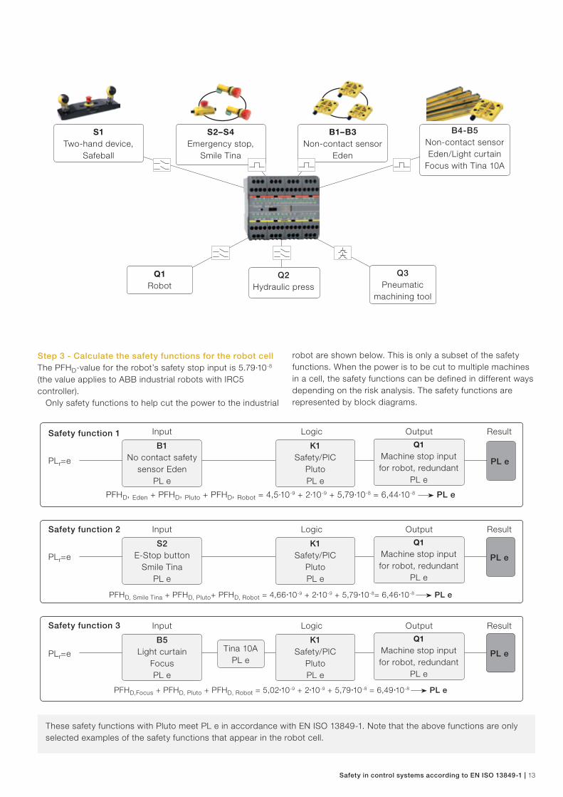
Step 1 – Risk assessmentThe workpieces to be machined are fed into the cell through a conveyor belt and positioned by the operator in the pneumatic machining tool in station 1. The operator starts station 1 manually. The pneumatic machining tool performs work on the workpiece in station 1. The operator then places the machined workpiece on the conveyor belt for transfer to station 2. The robot then takes the workpiece that is placed in the hydraulic press. The workpiece leaves the cell by transport out onto the conveyor. The work that needs to be done in station 2 is, for example, to address operational disturbances in the press and the robot (a few times a week, F2).
Unexpected start-ups of the robot are expected to cause serious injury (S2). The operator is deemed not to have the possibility of avoiding injury as the robot moves quickly (P2). The assessment for the safety function required for access to station 2 is PLr=e (S2, F2, P2). This assessment would still be the same in respect of the press. For the safety function for the risks associated with the conveyor belt, the assessment S1, F2, P1 is made giving PLr= b.
Step 2 – Reduce the riskAs protection, interlocked doors are selected with the Eden non-contact sensor. Station 1 with the pneumatic machining tool is operated by a two-hand device. When the two-hand device is released, the dangerous movement will be stopped safely. Station 2 can be in automatic mode, when a light curtain (Focus) and a non-contact sensor at door 4 (Eden) protects the entry. If the door is opened or the light curtain
is breached, station 2 stops in a safe manner. By opening doors 2 and 3 (also monitored by Eden) the conveyor belt and the pneumatic machining tool will stop safely. Manual reset must always be done after actuation by any safety device.
When the protection system requires a number of safety devices and that multiple machines must be checked, safety PLC Pluto is the most effective solution. If the protection system also has to work by zones and in different modes of operation, this is another compelling reason to use Pluto. With Pluto, PL e can be achieved regardless of the number of connected safety devices.
PLr= e for the robot and hydraulic press and PLr=b for the conveyor belt.
Safety PLC PlutoMonitors safety components.
Station 2
Station 1
low risk low risk
high risk high risk
Robot Conveyor belt
Door 4
Door 3Door 2
Door 1
Protection layout for a machining tool and industrial robot with high risks.
Safety in control systems according to EN ISO 13849-1 | 13
Step 3 - Calculate the safety functions for the robot cellThe PFHD-value for the robot’s safety stop input is 5.79·10-8 (the value applies to ABB industrial robots with IRC5 controller).
Only safety functions to help cut the power to the industrial
robot are shown below. This is only a subset of the safety functions. When the power is to be cut to multiple machines in a cell, the safety functions can be defined in different ways depending on the risk analysis. The safety functions are represented by block diagrams.
These safety functions with Pluto meet PL e in accordance with EN ISO 13849-1. Note that the above functions are only selected examples of the safety functions that appear in the robot cell.
B1–B3 Non-contact sensor
Eden
S2–S4 Emergency stop,
Smile Tina
Q3Pneumatic
machining tool
Q1 Robot
PFHD, Eden + PFHD, Pluto + PFHD, Robot = 4,5·10-9 + 2·10-9 + 5,79·10-8 = 6,44·10-8 PL e
PFHD, Smile Tina + PFHD, Pluto+ PFHD, Robot = 4,66·10-9 + 2·10-9 + 5,79·10-8= 6,46·10-8 PL e
PFHD,Focus + PFHD, Pluto + PFHD, Robot = 5,02·10-9 + 2·10-9 + 5,79·10-8 = 6,49·10-8 PL e
PLr=e
Safety function 1K1
Safety/PlCPlutoPL e
LogicQ1
Machine stop input for robot, redundant
PL e
Output
PLr=e
ResultSafety function 2
PLr=e PL eTina 10APL e
Safety function 3
PL e
PL e
Q1Machine stop input for robot, redundant
PL e
Output
Result
Result
K1 Safety/PlC
PlutoPL e
Logic
K1 Safety/PlC
PlutoPL e
Logic
S2 E-Stop button
Smile TinaPL e
B1No contact safety
sensor EdenPL e
B5 Light curtain
FocusPL e
Input
Q2Hydraulic press
B4-B5Non-contact sensorEden/Light curtain
Focus with Tina 10A
S1 Two-hand device,
Safeball
Q1Machine stop input for robot, redundant
PL e
Output
Input
Input
14 | Safety in control systems according to EN ISO 13849-1
SF1
SF3
SF2K1
Logic unit
S1E-Stop button
F1Light curtain
Q1Machine
B1Interlocked switch
S1E-Stop button
Q3Machine 3
B1Interlocked switch
F1Light curtain
Q1Machine 1
Q2Machine 2
K1Logic unit
What defines a safety function?
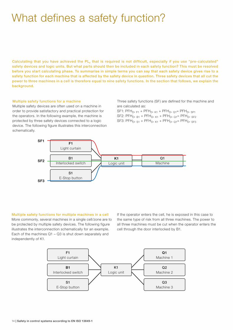
Multiple safety functions for a machineMultiple safety devices are often used on a machine in order to provide satisfactory and practical protection for the operators. In the following example, the machine is protected by three safety devices connected to a logic device. The following figure illustrates this interconnection schematically.
Calculating that you have achieved the PLr that is required is not difficult, especially if you use “pre-calculated” safety devices and logic units. But what parts should then be included in each safety function? This must be resolved before you start calculating phase. To summarise in simple terms you can say that each safety device gives rise to a safety function for each machine that is affected by the safety device in question. Three safety devices that all cut the power to three machines in a cell is therefore equal to nine safety functions. In the section that follows, we explain the background.
Three safety functions (SF) are defined for the machine and are calculated as:SF1: PFHD, F1 + PFHD, K1 + PFHD, Q1= PFHD, SF1SF2: PFHD, B1 + PFHD, K1 + PFHD, Q1= PFHD, SF2SF3: PFHD, S1 + PFHD, K1 + PFHD, Q1= PFHD, SF3
Multiple safety functions for multiple machines in a cellMore commonly, several machines in a single cell/zone are to be protected by multiple safety devices. The following figure illustrates the interconnection schematically for an example. Each of the machines Q1 – Q3 is shut down separately and independently of K1.
If the operator enters the cell, he is exposed in this case to the same type of risk from all three machines. The power to all three machines must be cut when the operator enters the cell through the door interlocked by B1.

Safety in control systems according to EN ISO 13849-1 | 15
Conclusions• Use the practical approach.• Use safety devices/logic units with high reliability (low PFHD) to make it easy to achieve the PLr required.• With Vital or Pluto, it is easier to achieve the PLr required.
Theoretical approach for multiple machinesThe theoretical approach to calculate the safety function is as follows:
Practical approach for multiple machinesA more practical approach is to divide the safety function into three parts, one for each of the three machines.This is an approach that can provide a more accurate way of
Sources:www.dguv.de/ifa/de/pub/grl/pdf/2009_249.pdfwww.bg-metall.de/praevention/fachausschuesse/ infoblatt/deutsch.html (No 047, Date 05/2010)
For the full safety function to be performed you require all the components to be working. Note that if B1 or K1 has a dangerous malfunction, the entire safety function is disabled. However, if for example machine Q1 has a dangerous malfunction, and is not shut down, machines Q2 and Q3 will still be shut down. One disadvantage in considering the safety function in this way is that you may have trouble achieving the PLr required. But if you achieve the PLr required, you can use the theoretical approach.
The risk assessment for the safety functions needed for the risks associated with the robot was S2, F2, P2, which resulted in PLr=e. The same assessment was made for the hydraulic press: PLr=e. The assessment of the pneumatic machining tool is S2, F2, P1 giving PLr= d due to the fact that the assessment is that there is the possibility of avoiding risk.
Interlock switch B1, Eden, is to cut the power to all machines in the danger zone: • Robot Q1 (PFHD, Q1 = 5.79·10-8) • Hydraulic press Q2 (PFHD, Q2 = 8·10-8) • Pneumatic machining tool Q3 (PFHD, Q3 = 2·10-7).
looking at the safety functions, especially where a different PLr is required for the safety functions above. If machine Q1 is a robot and machine Q2 is a conveyor which is designed to have negligible risks, the different PLr required to protect against risks from Q1 and Q2 will also be different. This practical approach is therefore the one recommended. The interpretation is based on information provided by IFA (Institut für Arbeitsschutz der Deutschen Gesetzlichen Unfallversicherung). For more information on this and other issues, see Sources.
Theoretical approachIf you use the practical approach the safety functions are as follows:
Robot:PFHD, B1 + PFHD, K1 + PFHD, Q1 = 4,5·10-9 + 2·10-9 + 5.79·10-8 = 6.44·10-8 PL e
Hydraulic press:PFHD, B1 + PFHD, K1 + PFHD, Q2 = 4.5·10-9 + 2·10-9 + 8·10-8 = 8.65·10-8 PL e
Pneumatic machining tool:PFHD, B1 + PFHD, K1 + PFHD, Q3 = 4.5·10-9 + 2·10-9 + 2·10-7 = 2.07·10-7 PL d
This is to be done in a similar way with other safety functions for the cell. For each safety device, you define the machines it affects, and establish the various safety functions according to this.
Theoretical approachHow would it have worked if you had used the theoretical approach? Would the safety function have achieved PL e?
All machines:PFHD, B1 + PFHD, K1 + PFHD, Q1 + PFHD, Q2 + PFHD, Q3 = 4,5·10-9 + 2·10-9 + 5.79·10-8 + 8·10-8 + 2·10-7 = 3.44·10-7 PL d
In this case, the safety function would therefore have not achieved a total PL e, which was required for the risks associated with the robot and hydraulic press.
B1Interlocked
switch
Q1Machine
1
K1Logic unit
Q2Machine
2
Q3Machine
3
K1Logic unit
Q3Machine 3
K1Logic unit
Q2Machine 2
B1Interlocked switch
B1Interlocked switch
B1Interlocked switch
K1Logic unit
Q1Machine 1
Examples of safety functions from Case Study 3 - safety PLC Pluto

16 | Safety in control systems according to EN ISO 13849-1
EN ISO 13849-1 requires calculations. To do this in a manageable way a software tool provides excellent help. ABB Jokab Safety has chosen to use SISTEMA, a software tool developed by BGIA, now called IFA, in Germany. The tool is freeware and can be downloaded from the IFA website, www.dguv.de/ifa. With SISTEMA it is possible to “build” safety functions, verify them and generate the technical documentation required.
To work with SISTEMA in a rational way, we have developed a library of our products for download from our website www.jokabsafety.se. In order to have access to the latest version, visit this page periodically to check for updates and new releases.
To download SISTEMA go to www.dguv.de/ifa/en/pra/softwa/sistema/index.jsp or search the Internet for “sistema”.
SISTEMAA tool for determining performance level (PL) and generating technical documentation
Screenshot from SISTEMA.

Safety in control systems according to EN ISO 13849-1 | 17
Pluto AS-i
To achieve PL e using a conventional safety relay, such as RT9, you need to use both channels on the input side and only connect a single safety device. Under certain conditions PL d can be achieved by connecting multiple two-channel devices to a safety relay, but this is not a generally accepted method. Vital is a safety controller that allows you to connect and monitor a variety of safety components in series, and to
Benefits of Pluto • Pluto is an all-master-system with communications
across a separate safety bus• Greater flexibility facilitates the design of protection
systems• One software for all systems• Easy programming for PL e by using function blocks
(certified by TÜV)
More than 30,000 Pluto systems have been successfully installed.
Benefits of Vital• It is possible to connect up to 30 safety components
through a channel in line with PL e• No programming required• The option of combining various safety components
(e.g. emergency stop button and door contact)• Easy configuration of the circuit• Electromechanical switches can also be used (with
the addition of the Tina adaptation device)
More than 70,000 Vital systems have beensuccessfully installed.
Safety relay, Vital or Pluto?
achieve PL e to EN ISO 13849-1. The Vital module is based on a dynamic single-channel concept and can replace multiple safety relays. A similar solution, although more flexible, is safety PLC Pluto. Pluto, like Vital, is able to make use of dynamic signals to achieve maximum reliability.
Various benefits in comparison to EN ISO 13849-1
Programmable
Not programmable
Safety relayDouble static inputs that only test the switches each time they are used.
VitalDynamic "doubled up" safety signal that tests a sensor, for example, 200 times per second.
Flexibility
Number of machines/different stops
Traditional safety PLCMaster-Slave with static inputs
Pluto All-MasterSafety PLC with static and dynamic safety inputs.
Slaves
Master

18 | Safety in control systems according to EN ISO 13849-1
Focus light curtainwith finger detection
Production-friendly safety systems from ABB Jokab Safety
Magne magnetic lockto keep doors closed during a process
Smile emergency stopto stop machinery when there is a hazard
The Eden sensormonitors that doors are closed
Focus light beamto provide protection when entering an area
Pluto Safety PLC, Vital and safety relaysfor monitoring protection
Safeball control devicefor ergonomic and safe two-handed control
Smart stopping timerto assist in determining protection locations
Quick-Guard fencing systemprevents unauthorised access and offers noise reduction
3-position devicedevicefor troubleshooting

Safety in control systems according to EN ISO 13849-1 | 19
AS-iProfibus DP
DeviceNet
Ethernet
CANopen
HMI
Product groups
Control devicesErgonomic three-position control units, two-handed control units and foot pedals.
Stopping time & machinery diagnosisUsed for stopping time measurement, annual maintenance and for trouble -shooting machinery.
Sensors/switches/locks Dynamic non-contact sensors, safety switches, magnetic switches and locks.
Light curtain/light beam/scannerComplete range of light beams, light curtains and scanners.
Vital safety controllerDynamic safety circuit for multiple protection according to the highest safety category
Training & AdvicePractical application of standards and regulations, along with CE-labelling.
Emergency stop devicesEmergency stop devices for dynamic and static safety circuits.
Pluto Safety PLCA unique All-Master safety PLC fordynamic and static safety circuits.
Pluto AS-iProgrammable safety system AS-i where all units are connected to the same bus cable and the function of the unit is determined in the PLC program.
Tina adapter units Transformation of static signals to dynamic safety signals, etc.
Sadety relaysThe market’s most flexible safety relays for different protection purposes and categories.
Contact strips/Bumpers/Safety matsSensitive edges bumpers and safetys mats.
Fencing systems/SafeCAD/Roller doorsA stable and flexible fencing system that is easy to install.
Knox safety lockensures that doors are locked
Roller doorsfor short protection distances and noise reduction
Sensitive edgesprevents against trapping injuries
Dalton process lockto keep doors closed during a process
Emergency stop Incafor enclosure installation
Operational mode locked and reset
ResetOpenable
Open

Contact us
ABB AB Jokab SafetyTel. +46 300-67 59 00www.abb.com/lowvoltage
2TL
C17
2003
B02
002
AB
B J
okab
Saf
ety,
201
1