safety, installation, maintenance, and operation 6422
TRANSCRIPT
1
OWNER’S MANUAL
Safety, Installation, Maintenance, and Operation
6422 Journeyman Electric Crane
Manual # 700-20032 Revision Date 4/04/2017
Summit Truck Bodies 990 Vernon Road
Wathena, KS 66090 866-985-3100
Fax: 785-989-3563 www.summitbodies.com
Subject to Change without Notification

2

3
Summit Truck Bodies Warranty Registration Fax Transmission
To: Warranty Department Fax: (785) 989-3563
From: Date:
Re: Product Registration Pages:
End user information: (Required for Warranty Activation)
Name: Phone:
Address:
City: State: Zip:
Contact: E-mail Address:
Distributor Information (Required for Warranty Activation)
Name: Phone:
Address:
City: State: Zip:
Contact: E-mail Address:
Product Information (Required for Warranty Activation)
Model Number: Serial Number:
Date Product Delivered: Date Processed:*
VIN Number of Truck: *For Summit Use Only
ONE REGISTRATION FORM PER UNIT (CRANE OR BODY) Registration form must be mailed or faxed within 15 days of customer installation.
Mail to:
Warranty Department Summit Truck Bodies
990 Vernon Road Wathena, KS 66090

4

5
Summit Truck Bodies Crane Owner’s Manual – Revision Record
REVISION RECORD Date
Section(s) or Page(s) Revised
Description of Change
4/14/17 Initial Release Initial Release of Manual
Notes:
1. The information contained in this manual is in effect at the time of this printing. It does not cover all instructions, configurations, accessories, etc. If you require additional information, please contact Summit Truck Bodies at (866) 985-3100.
2. Summit Truck Bodies reserves the right to update this material
without notice or obligation.

6

7
TABLE OF CONTENTS
Summit Truck Bodies Warranty Registration ............................................................................ 3 REVISION RECORD ................................................................................................................ 5 INTRODUCTION ...................................................................................................................... 9 SAFETY DECALS .................................................................................................................. 14 SPECIFICATION SHEET ....................................................................................................... 17 IONS ......................................................................................................................................... 19
STABILITY CAPACITY CHART ........................................................................................... 23
2.1 GENERAL ...................................................................................................................... 25 REFERENCE ASME B30.5a AND OSHA 1910.180 ............................................................. 25 FOR COMPLETE MAINTENANCE AND REPAIR REQUIREMENTS ............................. 25
2.2 LOAD LIMITS ............................................................................................................... 25 2.3 EQUIPMENT INSPECTION ......................................................................................... 25 2.4 OPERATING RESTRICTIONS ..................................................................................... 25 2.5 LOAD LIFTING ............................................................................................................. 26 2.6 OPERATION OF OUTRIGGERS .................................................................................. 26 2.7 WIRELESS CONTROL INSTRUCTIONS ................................................................... 26
SECTION 3 – MAINTENANCE ............................................................................................. 28 3.1 GENERAL ...................................................................................................................... 28 3.2 LUBRICATION .............................................................................................................. 28 3.3 HYDRAULIC FLUID .................................................................................................... 28 3.4 HYDRAULIC OIL DETERIORATION ........................................................................ 29 3.5 HYDRAULIC SYSTEM PURGING ............................................................................. 29 3.6 PURGING AIR FROM THE SYSTEM ......................................................................... 29 3.7 SYSTEM RELIEF PRESSURE ..................................................................................... 30 3.8 COUNTER BALANCE VALVE .................................................................................... 30 3.9 ROTATION GEAR ......................................................................................................... 30 3.10 PLANETARY WINCH ................................................................................................. 30 3.11 WIRE ROPE ................................................................................................................. 31 3.12 GEAR-BEARING BOLTS ........................................................................................... 32 3.13 INSPECTIONS ............................................................................................................. 33
Daily Inspection ................................................................................................................. 33 Weekly Inspection ............................................................................................................. 33 Monthly Inspection ............................................................................................................ 33 Quarterly Inspection .......................................................................................................... 34
LUBRICATION & MAINTENANCE SCHEDULE ........................................................... 34 SECTION 4 - TROUBLE-SHOOTING .................................................................................. 35

8
SECTION 5 - PARTS ............................................................................................................... 37 Summit 6422 Journeyman Pedestal Assembly.................................................................. 37 Summit 6422 Journeyman Pedestal Assembly.................................................................. 38 Summit 6422 Journeyman Boom Assembly ..................................................................... 39 Summit 6422 Journeyman Boom Assembly ..................................................................... 39 Summit 6422 Journeyman Stinger Assembly ................................................................... 45 Summit 6422 Journeyman Traveling Block Assembly ..................................................... 47
SECTION 6 - ELECTRICAL SCHEMATICS ........................................................................ 49 SECTION 7 - HYDRAULIC CONTROL VALVE SCHEMATIC .......................................... 50
Limited Warranty .................................................................................................................... 51

9
INTRODUCTION READ CAREFULLY
Congratulations on your purchase. You are the owner of what we consider to be one of the leading cranes in the service body field. This crane will provide you with both quality and safety if you follow the guidelines of working with a well-maintained piece of equipment in a safe manner using the correct personal protective equipment (“PPE”) for your work environment. Your crane carries a five(5) year warranty on all parts, weldments, and a three year warranty on the remote system. For continued quality service, carefully read the information contained in this manual before operating the equipment. This manual provides basic guidelines for the safe and proper operation of the crane. After you have read and understood the material in this manual, work with your crane by learning basic operations, safely.
To prevent injury to yourself or others, maintain your crane, and operate it safely by knowing your surroundings. Look out for such things as overhead wiring, overloading of the crane, side loading of the crane and wearing of the prescribed PPE.
The users must have a working knowledge of existing Federal, State and Local codes and regulations governing the safe use and maintenance of this crane.
This crane was tested to conform to the following code:
ANSI – ASME B30.5a – 2002 MOBILE AND LOCOMOTIVE CRANES
The American Society of Mechanical Engineers This crane carries a five (5) year warranty, but the warranty will be null and void if the crane is misused or abused by overloading, side loading, pulling a load through open terrain, lack of maintenance as directed in this manual, or making modifications to the crane without the express permission of Summit Truck Bodies.
Treat the equipment with respect and service it regularly. These two things can add up to a safer working environment, longer equipment
life, and prevention of loss of life and limb. Summit Truck Bodies issues a limited warranty certificate with each unit sold.
See last page for warranty.
Distributor Assistance: Should you require any assistance not given in this manual, we recommend that you consult your nearest Summit Truck Bodies
Distributor. Our distributors sell authorized parts and have service departments that can solve almost any needed repair. This manual does not cover all maintenance, operating, or repair instructions pertinent to all possible situations. If you require
additional information, please contact Summit Truck Bodies at the following telephone number: (866) 985-3100. The information contained in this manual is in effect at the time of this printing. Summit Truck Bodies reserves the
right to update this material without notice or obligation.

10
SAFETY
Of all the pages within this manual pay particular attention to this chapter. It could prevent serious injury, or worse, loss of life, to you or the people with whom you are working. After reading this chapter, put safety into practice on the job while operating your equipment or any other piece of machinery.
The first priority of any job must always be a safe working environment. You will eliminate personal pain and suffering to yourself and to others on the job site. Know your surroundings, power lines, loose soil not allowing for solid footing and lack of PPE, and maintain a mindset of working safely, from the beginning to the end of each job. This is not an all-inclusive list, so the owner of the machinery may want to supply its own list of safety precautions as well. However, follow the safety requirements listed and you will have the basic knowledge of safety on the job.
To qualify as a safe operator you should first know and understand your equipment, knowing its limitations and strengths. Maintenance of the equipment is second priority; as with any piece of machinery, if not kept clean and in working order, the equipment will likely malfunction. Follow a preventive maintenance schedule with your machine and a routine visual inspection of the equipment before you start any job.
The operator must have a working knowledge of all safety and government regulations. You can refer to any OSHA manual for guidance. Summit Truck Bodies is not liable for accidents caused by the operation of the crane.
You may want to follow a couple of safety tips. Equipment on your truck should include a fire extinguisher and a first aid kit. Use best practices of PPE and avoid any type of body jewelry that might get caught on moving objects.
The truck is equipped with a working surface on the bumper. Avoid using moving parts of the truck as a foothold or handhold; use the grab bars and steps designed for this purpose. Avoid walking under a load, and never use the crane as a mode of transportation from the ground level to an elevated surface.
General
Being the owner of the equipment, it is your responsibility to establish a training process for your operators by qualified people before starting the job. As with any equipment, be it a motor vehicle or machinery, this equipment cannot be operated by anyone under the influence of alcohol, drugs, or prescription medication that impairs the operator physically, mentally or physiologically.

11
Personal Safety
The use of personal protective equipment (“PPE”) is critical to the safety of the operation and the wellbeing of the people operating the equipment. The use of the following (but not all inclusive) PPE in the safe operation should be worn by the operator:
Protective helmets Safety shoes (preferably steel toed) Cut proof gloves, preferably snug fitting Ear plugs or any form of hearing protection Safety glasses or shields Reflective vests
Follow your established safety rules and regulations. If you do not have those, consult your OSHA manual. Routine inspection of the safety decals is a must for the safety of the operator; be sure all decals are legible and in good condition. Replace any and all decals that are missing from your truck body or in need of repair.
For the safety of the operators, follow these safety guidelines:
Disengage the power source before working on the equipment. Remember there is stored hydraulic pressure in the hydraulic lines of the truck; this must be
released prior to working on the crane components or any part of the hydraulic system. Stay clear of all moving parts of the equipment; your body could be crushed or severely
pinched. Routine maintenance should be recorded and maintained by only trained and competent
personnel. Bypassing parts of the wiring and/or plumbing can cause the crane serious damage and injury
to the operator. Stability
The service truck should be parked on solid level ground. If unable to park on such a surface, outrigger pads may need to be used to level and support the truck and its load.
Never exceed the crane capacity chart nor the stability chart for the service truck. These ratings are based on tested capacities of the service truck and the structural design and mechanical abilities of the components on the crane.
Be aware of the abilities and limitations of your crane. Improper use of the crane could damage the crane, service truck, lifted load, surroundings or even cause injury or death.
Park the vehicle on as level ground as possible. Use outrigger pads if needed, and always extend the outriggers fully out and then down.

12
Be aware of your surroundings when lowering outrigger jacks. Keep feet and legs out from under jacks. Never operate the crane before the service truck is positioned on stable, level ground. Put the vehicle in park or neutral (for manual transmissions) and set the parking brake before attempting a lift.
Load Safety
Before lifting a load know the weight you are preparing to lift. Also, consult your capacity chart located on the rear of the truck, comparing the two to ensure the crane will safely handle the job.
The crane has a safety built into the remote and receiver to prevent an overload, but like any mechanical device, it can be overridden by an operator. Please be advised that if this happens, your warranty is null and void. Consult with our service department to return the crane safety features back to the required setting established at the plant.
The traveling block is equipped with a safety hook at the point of attachment to a load. Always make sure the load is secured to the hook with the safety latch in the closed position on the hook prior to lifting the load. You can find directions in any OSHA manual.
The gear rotation mechanism is equipped with a ring and pinion gear; these are not designed for side loading of the crane, and side loading will result in failure of the gears.
A load suspended overhead should be avoided; never walk under one. When you leave the truck for a break or lunch, lower the load to the ground, as it can
result in injury if the load were to become unstable in your absence. Keep all people away from the suspended load; never position the load over a person. Dragging the load with either the winch or the boom will result in damage to the
equipment and could cause injury to the people around the load. The crane boom is designed to lift; it is not intended to be used to force a downward
pressure on any type of operation. Environment
The equipment you have purchased operates at maximum performance if you have a good preventive maintenance program in place. The work site is generally full of contaminants, so weekly washing of the truck and or crane is a good prevention tool. The use of lubricants on mechanical parts on the equipment should be followed on a weekly, monthly and quarterly basis. Prevention of the general wear and tear due to corrosives is insurance that your machine will last a long time, affording you a good investment of your time and capital.

13
Good common sense goes a long way in safety. Steel and electricity do not mix well, so avoid using the crane at the highest point on many job sites during a storm. Maintain the prescribed clearance from all power lines with your crane.
Maintenance Safety
Your Summit truck or crane is designed to give you years of use. Do not modify the components or the systems of the truck, as this will cause damage to the equipment and impede the functions of the truck.
Electrocution
Use extra personnel to signal when operating near electrical.
Keep at least ten feet between any portion of the crane and an electrical line. Add an additional 12" for every additional 30,000 volts or less.
Allow extra space during windy conditions for swaying power lines.
Death or serious injury can occur when working during electrical storms or near power lines.

14
SAFETY DECALS Decal Number: 700-30347 Title: Danger, two blocking the crane. Description: To inform the operator to not allow book block to come in contact with boom tip by hoisting up, extending or lowering the boom. Location: boom tip.
Decal Number: 700-30340 Title: Notice, lubricate worm gear Description: lubricate worm gear per schedule. Do not run if gears are dry. Location: pedestal bottom. Decal Number: 700-30339 Title: Caution, do not use the stow hook For lifting. Description: informs the operator to not use the The stow hook for load lifting. Location: pedestal bottom. Decal Number: 700-30373 Title: White outline logo Description: Identifies Summit Truck Bodies as the Manufacture of the crane. Location: Lower boom sections in the middle, both sides.

15
Decal Number: 700-30131 Title: Danger, Scissor point. Description: Notifies the operator of potential scissor Point. Location: Both sides of the lift cylinder. Decal Number: 700-30025 Title: Warning, overload hazard. Description: warns the operator not to tamper With the check valves. Location: Both sides of the lift cylinder.
Decal Number: 700-30342 Title: Notice, Crane design Specifications. Description: Informs the operator that this crane has been designed and manufactured to ASME/ANSI specifications. Location: Crane Pedestal. Decal Number: 700-30353 Title: Angle Indicator LH. Description: Informs the operator of the angle of the crane boom. Location: Left side, base boom.
Decal Number: 700-30018 Title: Angle Indicator RH. Description: Informs the operator of the angle of the crane boom. Location: Right side, base boom.

16
Decal Number: 700-30411 Title: Crane control, manual operation. Description: Informs the operator how to override the crane solenoid valves for manual operation. Location: Shield, hydraulic valve.
Decal Number: 700-31107 Title: Serial number plate. Description: Informs the operator of the crane identification serial number. Location: Shield, hydraulic valve, rear.
Decal Number: 700-30589 Title: Crane certification statement. Description: Informs the operator that the crane meets all federal & SAE standards specifications. Location: Pedestal, side plate.

17
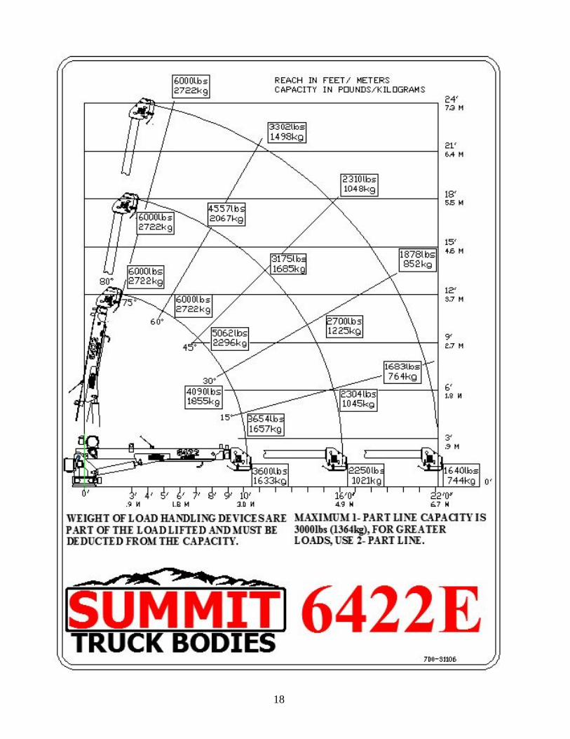
Specifications Model 6422 Journeyman Electric Crane SPECIFICATION SHEET
Crane Rating: 36,000 ft-lbs (5.49 ton-meters)
Standard Boom Length: 10’5 3/4"(3.2 m) from CL of Crane
Boom Extension: 1st stage: Hydraulic 71 3/4"(1.8 m)
2nd stage: Hydraulic 72"(1.8 m)
Maximum Horizontal Reach: 22’ 2”(6.8 m) from CL of Crane
Maximum Vertical Lift: 24’ 1”(7.4 m)
(from crane base)
Boom Elevation: -10 to +80 degrees
Stowed Height (crane only) 38 1/4” (97.2cm)
Mounting Space Required 18” x18” (45.7 x 45.7 cm)
Approximate Shipping Weight 1,817 lbs. (824.2 kg)
Controls Radio control standard for all functions.
Winch Specification
Rope Diameter: 5/16" (.79 cm)
Line pull speed: 30 ft/min (9.1 m/min)
Rotation: (worm gear) Continuous 360° power
Hydraulic System 2500 psi max
Oil Type Dexron II,III, or Mercon ATF
Lifting Capacities 3,600 lbs @ 10’0"(1,633 kg @ 3.05m)
2,250 lbs @ 16’0"(1,021 kg @ 4.88m)
1,640 lbs @ 22’2"(744 kg @ 6.75m)
Power Supply Required 12v, .13 ci displacement, 2 gal reservoir
(1.3 gpm @ 2500 psi)
*Subject to change without notification
18

19
IONS
General Dimensions for a 6422 Journeyman Crane

20
SECTION 1 – INSTALLATION
Your crane may have been purchased separately, and if you intend to mount it to your truck body, please follow the instructions to avoid accidents and/or injury to yourself and others. If you have a manual for your particular truck body, it likely has an instruction guide to help you in the mounting of the crane. Knowing your truck’s capacity will allow you to make the best installation possible for your application. Pay particular attention to the following:
1. Chassis capacity. 2. Total GVW after the crane is installed. 3. Whether your truck body has a crane mounted to it, and what weight it will hold. 4. Your crane weight depends upon which size crane you purchased, so the truck body will have
requirements as well; find out what the body manufacturer recommends before mounting your crane.
5. Disregarding these issues can result in serious injury or death to yourself or your operator. Before installing the crane to your truck body read and understand the guidelines established under federal law (Title 49 cfr part 568.6). Pay particular attention to Sec. 567.5 of the law. As the end user and installer of the crane to your truck body, you are required to certify the vehicle in compliance with Federal Motor Vehicle Safety Standards and other regulations issued under the National Traffic and Motor Vehicle Safety Act. You can go online at http://www.gpoaccess.gov/nara/index.html for further information. You are responsible for the truck to comply with all applicable federal and state regulations.
1. The weight of the truck must coincide with the chassis requirements of the crane to be installed. For the 6422 crane the following chassis requirements must be met: Minimum Chassis GVW: 19,500 lbs.
2. Any modifications made to the truck body must be approved by the body manufacturer and will properly and safely support the weight of the crane you have chosen to install.
3. Any components used to modify the crane and/or Summit Body will void the warranty and liability of the manufacturer.
4. The crane boom must be supported during transportation; thus, a boom cradle is required on the body.
5. To avoid injury, use a lifting device designed to bear the weight of the crane. 6. Lower the crane into place with the boom facing the rear. Make sure the crane is resting
properly on its base. Apply Loctite Thread locker #277 to the mounting bolts and install them from the underside of the mounting plate. Torque the (4) 3/4”bolts to 380 ft lbs.

21
7. Once mounted your Journeyman crane should be connected to the vehicle’s 12VDC electrical system using the 30’ power cable supplied with the crane. The following parts are included in the electrical kit shipped with the crane. a) Fuse Holder and Fuse b) Remote Controller c) Qty 4 ea.1-8 x 4” Grade 8 Mounting Bolts d) Qty 4 ea.1-8 top Lock Nuts e) 30’ power cable
Electrical Hook-up Diagram
Run the 30’ of power cable through the truck frame and up into the engine compartment. Attach the cable power eyelet to the center bolt position in the union under the pedestal as shown above. Attach the ground strap to the 5/16-18 hole just to the side of center (see illustration above). Tighten the fasteners. Care should be taken to protect the power cable from abrasion, flying gravel, hot exhaust pipes etc. by fastening it inside the frame channel and using protective covering (loom, conduit etc.). Be sure to use rubber grommets or other protection when running power cable through steel bulkheads, etc. Mount the 250 amp Fuse Holder as close as possible to the battery and connect it to the

22
positive (+) post of the battery. When installing the fuse holder, it should be easily accessible in the event fuse replacement should become necessary. Install the parallel Cable from the negative terminal of the battery to the crane ground position making sure that good metal to metal contact is made. The cranes electric system’s ground completes the electrical circuit through the ground cable back to the vehicle battery. The factory ground provided in the vehicle is NOT sufficient to carry the current required by the crane. Without the addition of this extra ground cable, your crane will not operate to its’ rated capacity and damage to the crane’s electric motors, contactors or the vehicle electrical system may occur.
8. Battery Replacement: The vehicle’s original equipment battery should be replaced with a maintenance type deep cycle battery to handle the extra power requirements of the crane. Under normal usage, (up to 3-4 short operations per day) a single, 1000 CCA, Deep Cycle Truck battery should provide sufficient power for the crane as long as the vehicle is running at a fast idle while the crane is in use. An alternator of at least 100 amp rating is required. If longer duty cycle is anticipated, then a second battery maybe necessary. In this case BE SURE to provide circuit protection from shorting of the power cable either in the form of a circuit breaker of sufficient capacity or an inline fuse. Always coat all battery and power cable connections with a corrosion preventative coating. Remember, a small or weak battery system will result in poor crane performance and damage over time to motors and contactors.
9. After the crane has been installed, check for: a) Free movement through crane rotation. b) Sharp corners (which may cut into hose) and kinks. c) Abrasions and chafing. d) Tightness of fittings. e) Leaks. f) Check all bolts and pins. g) Visually inspect all welds for cracks, holes, etc. h) Slowly operate crane through all functions. Inspect all hoses, cylinders and structural members for proper operation. i) Return crane boom to its support, and the unit is ready for operation.
TESTING SHALL BE PERFORMED BY DESIGNATED PERSONNEL ONLY. 10. Prior to initial use, all new, altered, modified, or extensively repaired cranes shall be tested for
compliance with the operational requirements of this crane.
a) Test all functions to verify speed and operation. b) Check that all safety devices are working properly. c) Confirm operating controls comply with appropriate function labels. d) Test loads shall not exceed 110% of the manufacturer’s load rating. e) Written reports shall be maintained showing test procedures and confirming the adequacy of repairs.

23
NOTE: Under federal law, all crane mountings must be tested for stability. Every truck loaded or unloaded will have a different weight, thus affecting the stability of the truck when put under load. Once you have your truck loaded to your approximate hauling capacity, you must comply with the stability test for your truck weight.
To be in compliance, your truck must lift the weight designated on your capacity chart supplied with the crane, until such time the load cannot be lifted or the truck is in danger of tipping over. Record the actual test data on the stability chart, which must be stored in the truck by the operator for future reference to ensure a safe lift by the operator in the various positions of the crane boom. The Stability Capacity Chart must be completed by the crane installation personnel. Summit Truck Bodies takes no liability for the placement of a crane by an outside source. If you install a crane not designed for the body or chassis, your crane and the stability of it will fail. Summit Truck Bodies has completed an extensive testing of the crane and has formulated the Stability Chart to cover the truck body and chassis on which it is mounted. The following Stability Capacity Chart is to be used by the installer of the crane, who may be unaware of the stability of Summit Truck Bodies cranes being mounted on unknown bodies and chassis.
Zone 1, if the boom reaches full extension without becoming unstable, the crane is stable for this zone and 100% can be written in the Zone 1 data box.
If the truck becomes unstable prior to the crane achieving full extension, then retract the boom until the truck becomes stable. Then measure the horizontal reach in this position (center of rotation to end of boom). This is the stable horizontal location in this zone (stable horizontal location divided by maximum horizontal location multiplied by 100 equates to the percentage of rated capacity for this zone). Record this number in the data box for Zone 1 (this is the revised load capacity for this zone due to stability of the service truck).
Repeat for each zone until the worksheet is completely filled out (this is the revised capacity based on stability for this crane and service truck).
After the test has been completed, return the boom to the normal transport position.
11. Install all safety decals supplied with the crane in a visible area as close to the crane as possible. ART

24
25
SECTION 2 - OPERATION
2.1 GENERAL REFERENCE ASME B30.5a AND OSHA 1910.180
FOR COMPLETE MAINTENANCE AND REPAIR REQUIREMENTS For ease of operation, become familiar with your crane and truck combination. Practice lifting without a load, and then graduate to a small load, gradually becoming larger in load size. Do this prior to actually going to the job site to perform the job task. As with all jobs, there is an element of risk, so prepare the operator for emergency situations and, much like testing for a fire drill, they will master the situation with each practice.
2.2 LOAD LIMITS Know your lifting limits before you start. Study the charts supplied with your crane, the Load Chart and the Angle Indicator Plate. Exceeding the limits within the radius of operation can result in tipping of the truck and/or structure failure, voiding the warranty.
2.3 EQUIPMENT INSPECTION OSHA Regulation 1910.180 calls for frequent and periodic inspections. The inspection record must include the following:
1. Date of Inspection 2. Signature of the person doing the inspection 3. Serial number of the crane inspected 4. The certification record must be available upon request
Safety checks must be current and made prior to the operation of the crane. Follow the guidelines listed above as well as the following:
1. Structural Soundness: Inspect the unit for damaged members and loose fasteners. 2. Controls: Test for proper control operation. 3. Wire rope: Inspect for damaged, kinked or frayed winch wire rope. 4. Repairs: Correct all observed defects and malfunctions before putting the unit into service.
2.4 OPERATING RESTRICTIONS Guidelines for operating the equipment:
1. The truck must be level for all loading and unloading with the crane. 2. The emergency brake must be engaged prior to any crane operation. 3. The outriggers must be extended and setting on solid footings before operating the crane.

26
4. The boom will drag the wire rope and break the stowing hook on the boom if you fail to extend the wire rope prior to extending the boom.
5. Never lift the load any further off the ground than necessary. 6. Keeping the load close to the ground will help prevent lifting the load over the top of a
person or persons. 7. Rotating the load too quickly will result in an unstable load and could cause injury or
damage to the crane rotate gears. 8. Avoid power lines when at all possible; if you must make a lift near a power line, do so
with extreme caution, and make sure the boom at full extension clears the power line by at least 10 feet.
9. Lifting the rated load capacity should be the norm; over lifting will result in a safety failure or equipment breakage.
10. Never leave a load unattended. 11. Side loading of the load using the winch will result in damage to the crane assembly. 12. The crane is designed to lift a material load and should never be used to move people. 13. Due to the height of the crane, avoid electrical storms and/or high winds. 14. Do not attempt to make repairs to a crane while it is in operation. 15. Operate the crane rotate slowly, as the weight of the load will cause undue stress on both
the crane rotate and the load if you have to stop quickly. This could also cause injury or death.
16. The crane will rotate up to 360 degrees; do not attempt a full speed stop with the rotation gear and a full load, as undue stress will break the gears in the rotate.
2.5 LOAD LIFTING 85% of tipping is the normal computation for all load ratings. To ensure a safe lift, the crane must meet all manufacturers’ required mounting procedures. All lifts are to be completed with full extension of the outriggers, with the truck setting on a flat level surface. Follow your stability chart for all lifting ratings.
2.6 OPERATION OF OUTRIGGERS MANUAL OUTRIGGERS:
1. Rotate locking pin to release outrigger leg. 2. Pull out outrigger leg and rotate locking pin to lock outrigger leg in position. 3. Lower outrigger leg until it has firm contact with the ground. 4. Repeat for the opposite side.
2.7 WIRELESS CONTROL INSTRUCTIONS The crane comes standard with a wireless control system. At the bottom center is a green button “POWER ON” for powering up the transmitter. To turn the transmitter on, press the green “ON” button. Horn should sound anytime the “ON” button is pressed. Once released the transmit (TX) light in the upper left starts blinking. The red button at the top center is the “POWER OFF” switch

27
for turning off the transmitter. To turn the unit off, press the red “OFF” button and the yellow transmit light stops flashing. On the left side top 2 function buttons is a vertical row of 5 lights. The transmitter is powered by 2-AA alkaline batteries, located under the back cover of the housing. If the battery runs down, the red light will begin to flash. If the yellow light is rapidly flashing this indicates that the unit is transmitting.
Refer to the Transmitter Diagnostics Section for a detailed explanation of each light combination. In addition to the lights mentioned above there are eight function buttons. These functions from left to right are to be used to raise and lower the boom, raise and lower the hoist cable, rotate the crane, extend and retract the boom and honk the horn. To operate a function, press and hold one of the function buttons as shown to the left. Each function is labeled to the side of each button. Only one function can be activated at one time. KEEP DRY. Do not clean the transmitter or receiver under high pressure. If water or other liquids get on the receiver, immediately dry the unit off. WARNING: DISCONNECT THE RADIO RECEIVER BEFORE WELDING on the crane, load, or truck. Never weld with the power on. Failure to turn off or disconnect will result in the destruction of the radio receiver.

28
SECTION 3 – MAINTENANCE WARNING: Read the Following before maintaining any part of the crane. Only authorized and trained service personnel are to perform maintenance on the crane.
3.1 GENERAL To prevent damage to the equipment, a daily, weekly, monthly, and quarterly PM should be established within your company to keep the equipment operating at maximum levels. Follow all safety practices before undergoing maintenance on your equipment.
1. Set the emergency brake, and lower the crane to a resting position, keeping it supported by the crane cradle on the truck or a stationary support on the ground level. Remember your crane goes to -5 degrees.
2. Perform your company’s designated PM on the equipment. 3. Replacement parts are available through Summit Truck Bodies. 4. Any worn or broken parts should be replaced at this time.
Service
To better service your crane, you may find it helpful to follow these guidelines:
1. Identify (knowing what the problem is generally helps you find the solution). 2. Troubleshoot (identify multiple causes and use Form 1-10 to determine the cause of the
problem). 3. Repair or replace the worn items depending on which solution is the most cost effective for
your repair. 4. Do (make the necessary repairs and or adjustments). 5. Check (function all operations of the equipment to ensure that all components are working
properly). 6. Put the crane back into service.
3.2 LUBRICATION Follow the guidelines established in the manual for all lubrication requirements. Extreme heat or cold can adversely affect the life of the lubricant. Pay special attention to periods of heavy use of the equipment, as this will also shorten lubricant life.
3.3 HYDRAULIC FLUID This crane utilizes a self-contained motor/pump unit with an integrated hydraulic reservoir.
System oil is automatic transmission oil, Dexron II/III Mercon or equivalent. Level should be periodically checked and maintained at a full level for proper crane operation

29
*NOTE: These recommendations are based on normal working parameters. If operating in less than favorable conditions (excessive dust, moisture, etc.), be sure to check fluid level more frequently and fill as necessary
3.4 HYDRAULIC OIL DETERIORATION Hydraulic oil can and will break down over time and/or excessive use. To avoid contamination of the oil and possible damage to your hydraulic components, take a sample of the suspected oil and check for the following:
1. Using a clean glass jar, put in a sample of the suspected oil. 2. The oil may smell burnt or have a foul odor. 3. If the oil is not clear and clean, it may be contaminated; contaminated oil generally has a
cloudy appearance or is very dark. 4. If after a few minutes you find water at the bottom of the glass jar, it is time to change the oil.
Any of the above-listed issues will be cause for oil replacement.
3.5 HYDRAULIC SYSTEM PURGING The fluid should be changed after 3,000 hours of operation or every year, whichever occurs first. Follow these guidelines to purge the hydraulic system:
3.6 PURGING AIR FROM THE SYSTEM
If you have air in your system, you will detect a choppy, erratic condition within the system. If the condition is only prevalent on one system, then hold the operation of that system open until the cycle is complete. Move the operation in the opposite direction, holding the control in the open position. This should eliminate the air. Operate the crane to check the performance. If the system operates smoothly, then it is purged. If the system does not operate smoothly, follow the process again.
If air is trapped in the cylinder, it will cause an erratic “bumpy” condition. To remove the air, hold the affected control open after the function has “bottomed out”. Move the function in the opposite direction and again hold the control open. Operate the crane in a normal manner to determine if the air has been purged. If not, repeat procedure.
NOTE: Do not purge the system for the winch circuit function.

30
3.7 SYSTEM RELIEF PRESSURE
There is a pressure gauge on the crane hydraulic power supply leading to the manifold. This gauge will show system pressure. A test can be performed by utilizing the extend cylinder. Fully retract either cylinder and hold in while observing pressure reading on gauge.
1. Extend the boom until the cylinder is fully extended. Continue to hold the valve open and read the pressure on the pressure gauge. A reading of less than normal should be corrected by increasing the pressure. If the pressure reading is too high or too low, it will be necessary to adjust the relief valve set screw.
2. Adjustments are made by unlocking the jam nut and turning set screw clockwise to
increase pressure and counterclockwise to decrease pressure. The recommended pressure setting is 2800 PSI.
3.8 COUNTER BALANCE VALVE Your crane is equipped with hydraulic cylinders that have counter balance valves. These prevent the failure of the cylinder rods in a downward motion in the event there is a component failure within the hydraulic system.
Find the cylinder you suspect to be the problem. Test the cylinder with the crane intact. Safely lift a lighter load than the crane has capacity for, and then power off the hydraulic system. If the cylinder fails and allows the load to lower, it is time to replace the counter balance valve. If the cylinder does not lower, then the counter balance valve is operational and you have another issue that must be identified.
3.9 ROTATION GEAR All Summit Cranes are equipped with a gear products rotation gear. Gear products have a very good reputation in the industry, and it is recommended that no adjustments be made to the rotation system without prior approval. The suggested gear lube of choice is Castrol Molub-Alloy, 936 SF Heavy Lubricant or equivalent to grease the worm and/or ring gear.
3.10 PLANETARY WINCH No adjustments are to be made to the planetary winch without prior consultation with the factory. The planetary winch is only to be serviced by a trained technician, through the service department.

31
3.11 WIRE ROPE The entire safety of the crane and the lifting of loads will be determined by one item on your crane, namely, the condition of the wire rope. To do a thorough visual inspection goes without saying. This should be completed daily, as it requires very little time and could prevent injury.
Look at the entire rope as it is unwound from the winch, looking for worn or frayed cables within the rope. Check each end of the rope at the attachment points. Pay close attention to the ends for breakage and/or rust.
While the rope is unwound, check the winch drum for wear, as well as the sheaves for any unusual wear that may result in wire damage.
Good PM is required with the wire, as it is all important to the safety of the operator and the equipment.
A daily inspection of the wire rope should include a visual inspection for rust, frayed wire strands, a twist in the wire rope, and form of weakness that may have been the result of the wire rubbing on a porous surface.
Quarterly inspections are suggested for the safety of the personnel working on the job site. This inspection involves more than the suggested visual inspection done daily. The inspector can be the operator if you deem him to be a competent person with knowledge of the equipment and its features and functions.
1. The wire rope should be inspected for defects from start to finish of the rope. The wire rope should be replaced if there is evidence of wear, rust, and/or defects of any nature, such as twisted rope, frayed cables or broken wires. Making use of a micrometer is necessary when judging the diameter of the wire rope to determine the life expectancy of the rope.
2. The rope has weight associated with it so be cautious when near the ends of the rope.
When you have any, or a combination of, the following defects, the wire rope should be replaced:
1. Broken or frayed wires within the rope or at the ends of the rope. 2. If upon micrometer inspection you determine the wear pattern of the wire diameters to be
more than 1/32 inches. 3. If the wire has been exposed to an extreme heat, it needs replacement. 4. A distorted twist in the rope. 5. If you detect any stretching of the wire rope compromising the diameter of the original wire
diameter.
In order to properly maintain your wire rope, always keep it stored in the winch off the crane body, and a monthly lubrication with a quality lube such as LPS Chain Mate Chain & Wire Rope Lubricant will extend the rope life, never use WD-40. Avoid using the rope over sharp objects that may cause it to be scraped or situations where the rope can become caught, crushed or kinked.

32
3.12 GEAR-BEARING BOLTS Do not reuse any of the gear bearing bolts. These must be replaced using a bolt of identical specifications for size and grade. Reuse of the old bolt will result in a compromise of bolt integrity and could lead to a severe accident, causing loss of life and/or limb.
U.S. BOLT TORQUE SPECIFICATIONS Torque in pounds-foot
5 5 8 8
Socket head
Socket head
cap screw
cap screw
Bolt Thread Dry Oiled Dry Oiled Dry Oiled Dia. per inch
1/4 20 8 6 12 9 14 11 5/16 18 17 13 25 18 29 23 3/8 16 30 23 45 35 49 39
7/16 14 50 35 70 55 76 61 1/2 13 75 55 110 80 113 90
9/16 12 110 80 150 110 163 130 5/8 11 150 110 220 170 230 184 3/4 10 260 200 380 280 400 320 7/8 9 430 320 600 460 640 510
1 8 645 515 910 725 960 770 1 1/8 7 795 635 1290 1030 1375 1100 1 1/4 7 1120 900 1875 1500 1980 1585 1 3/8 6 1470 1175 2380 1900 2535 2030 1 1/2 6 1950 1560 3160 2525 3340 2670
BOLT TORQUE FACTORS LUBRICANT OR PLATING TORQUE CHANGES
Oil Reduce torque 15% to 25% Dry Film (Teflon or moly based) Reduce torque 50% Chrome plating No change Cadmium plating Reduce torque 25% Zinc plating Reduce torque 15%
The use of Loctite does not affect the torque values listed above.

33
3.13 INSPECTIONS
Daily Inspection Before going to the job site each day, a visual inspection of the following will help prevent unnecessary maintenance:
1. All fluid levels are within the tolerances set by the manufacturers, such as air compressor, crane and engine.
2. Evidence of broken structural components such as welds and loose fasteners. 3. Leaking cylinder seals. 4. Oil leaks at the engine, transmission, PTO and pump, power steering and hydraulic reservoir. 5. Wire rope inspection for excessive wear patterns. 6. Excessive wear to the counter balance valves to ensure the crane load will not be
compromised. 7. Outriggers operate as specified. 8. All safety devices are in place, in good working order and legible.
Weekly Inspection This inspection should be a routine and often easy inspection if daily inspections are being completed by competent personnel.
1. General inspection of lubrication capacities and levels. 2. General inspection of all crane components for wear and tear.
Monthly Inspection Establish a set time every month within which the monthly inspections will occur. The inspection should occur at the same time every month.
1. Check the entire truck for leaks, engine, transmission, crane, outriggers, hydraulic reservoir and all cylinders on the truck components.
2. Lubrication levels are within specifications set by the manufacturer. 3. Inspection of the crane hook and safety latch for wear and tear. 4. Check entire structure of the truck and components for broken welds, worn fasteners and
missing fasteners. 5. All safety devices are in good working condition and legible. 6. Inspect all wiring and lights on the truck for correct operations and functions. 7. Replacement of any non-conforming issues.

34
Quarterly Inspection This inspection should include, but not be limited to, the following:
1. Any loose bolts on the crane body. 2. Any bolts mounting the crane to the main body of the truck pedestal. 3. The hydraulic system pressures to the cylinders, main block assembly, and cartridges. 4. Lubrication of the pivot points of the crane such as the bearings, cylinders, and shafts. 5. Wear and tear of the hydraulic hoses such as fraying, crushing and leaks. 6. Undue wear of the PTO; follow the manufacturer’s maintenance manual. 7. Both the lift cylinder and the extend cylinder for leaks, drifting of the cylinders, and any
damage external of the cylinders.
LUBRICATION & MAINTENANCE SCHEDULE
SERVICE PERFORMED
DA
Y
WE
EK
LY
3 M
ON
TH
6 M
ON
TH
YE
AR
NOTES Load Hook X Inspect Hook & Latch for Deformation Winch Cable X Check for Broken Strands, Flattening, Deformation Cable Drum X Make sure cable is wound evenly on drum Pin Retaining Bolts X Check bolts for Proper Torque
Rotation Ring Gear X Lube with Castrol Molub – Alloy, 936 SF Heavy Lubricant or Equivalent
Sheaves X Inspect for wear and bearing fatigue
Mounting Bolts X Check torque to 680 ft lbs All other Bolts X Check and Tighten as required Rotation Gear Box X Grease zerks with multipurpose grease
CAUTION: Routine maintenance insures trouble-free operation and protects your investment. All warranties are void if maintenance is neglected. Notes:
1. Use only authorized parts. Any damage or malfunction caused by the use of unauthorized parts is not covered under Warranty or Product Liability. 2. Once a bolt has been torqued to its rated capacity and then removed, the bolt should be replaced with a new one.

35
SECTION 4 - TROUBLE-SHOOTING The following is meant as a reference in diagnosing on-the-job-malfunctions.
SYMPTOM
Crane will not operate.
Crane will not rotate.
Crane will operate manually but will not operate electrically.
Function does not respond to controls.
Two functions operate at the same time while only toggling
one function.
Slowdown of functions.
Unusual noise in operation.
Outriggers won’t react.
PROBABLE CAUSE
1. Parking brake is not engaged 2. Radio receiver does not have 12V power 3. Transmitter not on 4. Transmitter batteries have low voltage
1. Obstruction in control valve solenoid 2. Adjustable speed set improperly 3. Bad ground on the control valves 4. Rotation direction slope is too extreme (not on level ground)
1. Radio receiver does not have 12V power 2. Transmitter not on 3. Radio/Receiver not functioning properly 4. Parking brake is not engaged. 5. Parking brake switch is not working properly.
1. The toggle switch is not working properly 2. Ruptured/obstructed pressure line 3. Short circuit in remote control 4. Broken wire in remote control 5. Crane is not grounded to truck 6. Solenoid in control valve malfunctioning 7. Bad ground on the control valve
1. An obstruction in the solenoid control valve 2. The toggle switch has failed and is stuck in the “on” function
1. Relief valve set too low 2. Flow control valve not functioning properly 3. Proportional trigger on remote not functioning properly 4. Dirty filter/strainer 5. Obstruction in solenoid control valve
1. Cavitation due to low hydraulic oil supply 2. Excessive loading 3. Restriction/collapse of suction line 4. Flow control valve not functioning properly 5. Suction line filter dirty 6. Relief valve set too low 7. Relief valve defective 8. Air in the lines
1. Adjustment speed set improperly 2. Control valve defective 3. Loss of power and/or ground to coil

36
Boom drifts under load.
Boom or winch won’t lift.
Rotation speed too fast or too slow.
Winch brake will not hold.
Crane operates slowly.
With the Crane boom in a vertical position and the
warning indicator light on solid, the crane boom will not boom
down.
.
1. Cylinder piston seals leaking 2. Counterbalance valve defective
1. Restriction in the line 2. Relief valve is not set properly 3. Overload condition 4. Counterbalance valve is malfunctioning or defective
1. Hydraulic lines restricted or ruptured 2. Hydraulic motor defective
1. The back pressure on the return line of the winch is greater than 50 psi
2. Excessive loading 3. The winch relief valve not set properly 4. Counter balance valve not set properly
1. Air in the system 2. Pump not delivering rated oil volume 3. The holding valves are not operating 4. Hydraulic fluid low 5. Flow control valve restricted 6. Pressure relieve valve sticking open 7. Speed control option not engaged
1. The lift cylinder has extended full stroke and is in an over pressure state. To release the pressure, locate the far right solenoid as looking at the crane from the rear (view A). Push the center button (view B) in and pull the outer sleeve out (view C). This manually overrides the lift solenoid to power the lift cylinder down. With the button in and the sleeve pulled out activate the rotate function button, this will electrically power up the hydraulic power supply causing the lift solenoid to send hydraulic pressure to the lift cylinder causing it to retract enough to eliminate the over pressure condition turning off the red warning and allowing the crane to function normally again.
View A
View B
View C

37
SECTION 5 - PARTS
Summit 6422 Journeyman Pedestal Assembly

38
Summit 6422 Journeyman Pedestal Assembly BOM

39
Summit 6422 Winch Control Contactor Assembly Details

40
Summit 6422 Winch Control Contactor Assembly BOM

41
Summit 6422 Journeyman Base Boom Assembly

42
Summit 6422 Journeyman Base Boom Assembly BOM

43
Summit 6422 Journeyman Base Boom Wear Pad Assembly Details
Summit 6422 Journeyman Base Boom Wear Pad Assembly BOM

44
Summit 6422 Journeyman Intermediate Boom Assembly
Summit 6422 Journeyman Intermediate Boom Assembly BOM

45
Summit 6422 Journeyman Stinger Assembly

46
Summit 6422 Journeyman Stinger Assembly BOM

47
Summit 6422 Journeyman Traveling Block Assembly

48
Summit 6422 Journeyman Traveling Block Assembly BOM

49
SECTION 6 - ELECTRICAL SCHEMATICS

50
SECTION 7 - HYDRAULIC CONTROL VALVE SCHEMATIC

51
990 Vernon Rd Wathena, KS 66090
Phone (866) 985-3100 Fax (785) 989-3563
Summit Truck Bodies, LLC Limited Warranty
Warranty Period: 60 Months Summit Truck Bodies, LLC (hereinafter “Summit”) warrants each new crane of Summit’s manufacture to be free from defects in material and workmanship, under normal use and service for a period of five (5) years after initial purchase as derived from a completed warranty registration card. This Limited Warranty shall apply only to cranes of Summit’s manufacture. Parts are covered by a separate limited warranty. EQUIPMENT AND ACCESSORIES NOT OF SUMMIT’S MANUFACTURE ARE WARRANTED ONLY TO THE EXTENT OF THE ORIGINAL MANUFACTURER’S WARRANTY AND ARE SUBJECT TO THEIR ALLOWANCE TO SUMMIT ONLY IF FOUND TO BE DEFECTIVE BY SUCH MANUFACTURER. Warranty Terms During the Limited Warranty period specified above, any defect in material and workmanship in any warranted item of Summit bodies not excluded below shall be repaired or replaced at Summit’s option by a Summit representative or approved repair facility. Summit will pay for replacement parts and such approved repair shop’s labor in accordance with Summit’s labor reimbursement policy. Summit reserves the right to supply remanufactured replacement parts as it deems appropriate. Retail Purchaser Responsibility This Limited Warranty requires proper maintenance and periodic inspections of the crane as indicated in the Operator’s Manual furnished with each new Summit crane. The cost of routine maintenance and services is the responsibility of the retail purchaser. The retail purchaser is required to keep documented evidence that these services were performed. The Summit Truck Bodies, LLC Limited Warranty may be subject to cancellation if the above requirements are not performed. Summit cranes with known failed or defective parts must be immediately removed from service.

52
Exclusions and Limitations The warranties contained herein shall NOT APPLY TO: Any defect which was caused (in Summit’s sole judgment) by other than normal use and service of the crane or by any of the following: (i) accidents including but not limited to collision (ii) misuse or negligence (iii) overloading (iv) lack of reasonable and proper maintenance (v) improper repair or installation (vi) unsuitable storage (vii) non-Summit alteration or modification (viii) natural calamities (ix) vandalism Any crane whose identification numbers or marks have been altered or removed. Any crane which any of the required or recommended periodic inspection or services have been performed using parts not manufactured or supplied by Summit or meeting Summit specification. New cranes delivered to the retail purchaser in which the warranty registration is not returned within fourteen (14) days from the date of delivery. Any defect which was caused (in Summit’s sole judgment) by operation of the crane not abiding by standard operating procedures outlined in the Operator’s Manual. Costs incurred by Summit for replacement parts for items not of Summit manufacture will be invoiced to the customer. To be considered for warranty, the failed part must be returned, at the discretion of Summit, to Summit or the manufacturer of the part within fifteen (15) calendar days. The part will be evaluated and if warranty is approved by the manufacturer credit will be issued to the customer in the form of Credit to a Summit account if one exists or Credit back to a charge card or Check to the customer. Transportation costs, if any, of transporting unit to an approved repair facility. In no event shall Summit’s liability exceed the original purchase price of the product. Summit shall not be liable to any person under any circumstances for any incidental or consequential damages (including but not limited to loss of profits and out of service time) occurring for any reason at any time. Diagnostic and overtime premiums are not covered under this Limited Warranty Policy. Depreciation caused by normal wear, lack of reasonable maintenance, failure to follow operating instructions, misuse, or lack of proper protection during storage. Accessory systems and electronics not of Summit’s manufacture are warranted only to the extent of such manufacturer’s respective Limited Warranty, if any. Any installation of a crane on chassis other than original factory installation.

53
Parts Warranty Replacement parts after the original warranty period are warranted to be free from defects in material for ninety (90) days or the part will be repaired or replaced without labor coverage for removal or installation. Summit Labor Reimbursement Policy Summit will consider labor reimbursement during the defined warranty period provided that the repair is pre-approved. Contact the Service Department at Summit for details. Shipping Costs Summit will pay for shipping of warranty parts by ground carrier. Expedited freight delivery is available at the expense of the owner. Shipping for the return of parts for warranty consideration will be at the owners’ expense but will be reimbursed if the parts in question are deemed defective by Summit or by the manufacturer of the part and a legible copy of the invoice is provided. Exclusion of Warranties Except for the warranties expressly and specifically made herein, Summit makes no other warranties, and any possible liability of Summit hereunder is in lieu of all other warranties, expressed, implied, or statutory including but not limited to any warranties of merchantability or fitness for particular purpose. Summit reserves the right to modify, alter, and improve any product previously sold without incurring any obligation to replace any product previously sold without such modification. No person is authorized to give any other warranty or assume any additional obligation on Summit’s behalf. SUMMIT TRUCK BODIES IS UNDER NO OBLIGATION TO EXTEND THIS WARRANTY TO ANY CUSTOMER FOR WHICH AN SUMMIT CRANE WARRANTY FORM HAS NOT BEEN COMPLETED AND ON FILE WITH SUMMIT TRUCK BODIES.