safety interfaces
TRANSCRIPT
Safety. Detection. Control.
Safety Interfaces and Relays
Product catalogue
SAFETY INTERFACES
Issue 1

AD SR1 Type 4 interface for safety light curtains See page 3
AD SRM Type 4 interface with integrated Muting for light curtains See page 4
AD SRT PL e safety Interface for two-hand control See page 5
AD SRE4 / 4C PL e safety interfaces for emergency stop buttons and safety switches See page 6
AD SRE3 / 3C PL d safety interfaces for emergency stop buttons and safety switches See page 7
AU SX Type 2 control unit for ReeR Ilion and Ulisse photocells See See page 9
AU SXM Type 2 control unit with integrated Muting for ReeR Ilion and Ulisse photocells See page 10
2
MG d1 PL d control unit for ReeR Magnus magnetic switches. See page 8
SV MR0 - SV MR0 U PL e / SIL 3 safety speed monitoring interface. See page 11
AD SR0 / 0A Safety relay See page 12
SAFETY INTERFACES AND RELAYS
OVERVIEW

3
AD SR1
E S P E
SAFETY INTERFACES AND RELAYS
TYPE 4 INTERFACE FOR SAFETY LIGHT CURTAINS
TECHNICAL FEATURES
Safety relay outputs 2 NO - 2 A 250 VAC
Status output PNP – 100 mA at 24 VDC
Response time (ms) ≤ 20
Start/Restart command ac-cording to IEC 61496-1
Manual or automatic Start/Restart selectable on terminal block
Status displayLED indication of input/output status and diagnosis
Power supply (VDC) 24 ± 20%
Electrical connections On terminal blocks
Operating temperature (°C) 0 ... 55
Protection ratingIP20 for housing IP2X for terminal blocks
FasteningDIN rail fastening according to EN 50022-35 standard
Dimensions h x w x d (mm) 99 x 22,5 x 114
PART NUMBERS
AD SR1 safety interface includes multi-language instruc-tion manual and CE declaration of conformity.
Ordering code: 1330900
Interface module for safety light curtains EOS4 A, EOS2 A, Admiral AD, Admiral AX BK, Vision V. Includes self-testing solid state safety outputs.
■ Guided-contact safety relays ■ Start/Restart interlock ■ EDM Feedback input for extra external
contactors monitoring
APPROVALS • 2006/42/EC: “Machine Directive” • 2014/30/EU: “Electromagnetic Compatibility Directive” • 2014/35/EU: “Low Voltage Directive” • IEC 61496-1:2012 “Safety of machinery - Electro sensitive
protective equipment - General requirements and tests” • EN 61496-2:2013 “Safety of machinery - Electro-sensitive
protective equipment - Particular requirements for equipment using active opto-electronic protective devices (AOPDs)”
• IEC 62061:2005 “Safety of machinery - Functional safety of safety-related electrical, electronic and programmable electronic control systems”
• ISO 13849-1:2006 “Safety of machinery - Safety-related parts of control systems - Part 1: General principles for design”
• EN 50178:1997 “Electronic equipment for use in power installations”
• EN 55022:2010 “Information Technology Equipment - Radio Disturbance Characteristics - Limits and Methods of Measurement”
• UL (C+US) mark for USA and Canada • The S-Mark carries the same weight in Korea as the CE-Mark
does in Europe
SAFETY LEVEL
SILCL 3PL e - Cat. 4
TYPE 4

4
E S P E
SAFETY INTERFACES AND RELAYS
AD SRM
Interface module for safety light curtains EOS4, EOS2, Admiral, Vision (any resolution and heights), safety laser scanner Pharo.
■ 2-sensor logic integrated Muting ■ Guided contact safety relays ■ Start/Restart interlock ■ EDM Feedback input for extra external contac-
tors monitoring ■ Muting Time-out selectable ■ Integrated Override with 2 operating modes
selectable ■ Muting Enable input
APPROVALS • 2006/42/EC: “Machine Directive” • 2014/30/EU: “Electromagnetic Compatibility Directive” • 2014/35/EU: “Low Voltage Directive” • IEC 61496-1:2012 “Safety of machinery - Electro sensitive
protective equipment - General requirements and tests” • EN 61496-2:2013 “Safety of machinery - Electro-sensitive
protective equipment - Particular requirements for equipment using active opto-electronic protective devices (AOPDs)”
• IEC 62061:2005 “Safety of machinery - Functional safety of safety-related electrical, electronic and programmable electronic control systems”
• ISO 13849-1:2006 “Safety of machinery - Safety-related parts of control systems - Part 1: General principles for design”
• EN 50178:1997 “Electronic equipment for use in power installations”
• EN 55022:2010 “Information Technology Equipment - Radio Disturbance Characteristics - Limits and Methods of Measurement”
• UL (C+US) mark for USA and Canada • The S-Mark carries the same weight in Korea as the CE-Mark
does in Europe
TYPE 4 SAFETY INTERFACE WITH INTEGRATED MUTING FOR LIGHT CURTAINS
TECHNICAL FEATURES
Inputs for Muting sensors2 inputs 0 or 24 VDC - PNP or relay - dark-on
Muting Enable input 0 or 24 VDC – PNP or relay
Safety relay outputs 2 NO - 2A 250 VAC
Status output PNP – 100 mA at 24 VDC
Muting lamp output 24 VDC; 0,5 ... 5 W
Response time (ms) ≤ 20
Start/Restart command ac-cording to IEC 61496-1
Manual or automatic Start/Restart selectable on terminal block
Status displayLED indications of input/output status, Muting sensor inputs, diagnosis
Muting time-out 30 sec. or infinite, selectable
Override2 operating modes selectable: - manual action with hold to run - automatic with pulse command
Override time-out (min) 15
Power supply (VDC) 24 ± 20%
Electrical connections On terminal block
Operating temperature (°C) 0 ... 55
Protection ratingIP20 for housing IP2X for terminal block
FasteningDIN rail fastening according to EN 50022-35 standard
Dimensions h x w x d (mm) 99 x 35 x 114
PART NUMBERS
AD SRM safety interface includes multi-language instruc-tion manual and CE declaration of conformity.
Ordering code: 1330904
SAFETY LEVEL
SILCL 3PL e - Cat. 4
TYPE 4

5
AD SRT
E S P E
Certi�ed byTÜV NORDCERT GmbH
SAFETY INTERFACES AND RELAYS
PL E SAFETY INTERFACE FOR TWO-HAND CONTROL
TECHNICAL FEATURES
Safety relay outputs
2 NO + 1 NC - 6 A 240 VAC / 24 VDC
Each NO safety output line is interrupted twice by the two relays
Response time (ms) ≤ 30
Status displayLED indicators for status and supply dia-gnostic: power, channel 1 and channel 2
Power supply (VDC) 24 (-15 +10%)
Electrical connection On terminal block
Operating temperature (°C) - 25 ... 55
Protection ratingIP40 for housing IP20 for terminal block
FasteningDIN rail fastening according to E N 50022-35 standard
Dimensions h x w x d (mm) 99 x 22,5 x 114
PART NUMBERS
AD SRT safety relay includes multi-language instruction manual and CE declaration of conformity.
Ordering code: 1330915
Safety relay for two-hand control.
Input with 3 or 4 contacts for two-hand control unit.
Certified as Type III C according to the EN 574 standard, monitors the simultaneity between the two inputs (< 0.5 sec).
■ Guided-contact safety relays ■ EDM Feedback input for external contactors
monitoring ■ Can be used up to Cat. 4, PL e
APPROVALS • 2006/42/CE: “Machine Directive” • 2014/30/EU: “Electromagnetic Compatibility Directive” • 2014/35/EU: “Low Voltage Directive” • EN ISO 13849-1: “Safety of machinery - Safety-related
parts of control systems - Part 1: General principles for design”
• Type III C according to the EN 574 standard and monitors the simultaneity between the two inputs (< 0.5 sec)
• UL (C+US) mark for USA and Canada
SAFETY LEVEL
Cat. 4Type III C (EN 574)
PL e

6
E S P E
Certi�ed byTÜV NORDCERT GmbH
SAFETY INTERFACES AND RELAYS
AD SRE4 - AD SRE4C
Safety relay for emergency stop buttons and safety switches monitoring.
■ Guided-contact safety relays ■ EDM Feedback input for external contactors
monitoring
Start/Restart can be:
■ Automatic/Manual (AD SRE4 ) ■ Manual Monitored (AD SRE4C)
Both models can be used up to safety Category 4, PL e according to EN ISO 13849-1.
APPROVALS • 2006/42/EC: “Machine Directive” • 2014/30/EU: “Electromagnetic Compatibility Directive” • 2014/35/EU: “Low Voltage Directive” • EN ISO 13849-1:2008 “Safety of machinery - Safety-
related parts of control systems - Part 1: General principles for design”
• EN 60204-1:2006 “Safety of machinery - Electrical equipment of machines - Part 1: General requirments”
• UL (C+US) mark for USA and Canada
PL E SAFETY INTERFACES FOR EMERGENCY STOP BUTTONS AND SAFETY SWITCHES
TECHNICAL FEATURES
Safety relay outputs
3 NO + 1 NC - 5 A 240 VAC / 24 VDC
Each NO safety output line is interrupted twice by the two relays
Response time (ms) ≤ 50
Start/RestartAD SRE 4 - Automatic/Manual AD SRE 4C - Manual monitored
Status displayLED indicators for status and supply dia-gnostic: power, channel 1 and channel 2
Power supply (VDC) 24 (±10%)
Electrical connection On terminal block
Operating temperature (°C) - 25 ... 55
Protection ratingIP40 for housing IP20 for terminal block
FasteningDIN rail fastening according to EN 50022-35 standard
Dimensions h x w x d (mm) 99 x 22,5 x 114
PART NUMBERS
AD SRE4 and AD SRE4C safety relay includes multi-langua-ge instruction manual and CE declaration of conformity.
Ordering code AD SRE 4: 1330913 Ordering code AD SRE 4C: 1330914
SAFETY LEVEL
PL e - Cat. 4
PL e

7
AD SRE3 - AD SRE3C
E S P E
Certi�ed byTÜV NORDCERT GmbH
SAFETY INTERFACES AND RELAYS
PL D SAFETY INTERFACES FOR EMERGENCY STOP BUTTONS AND SAFETY SWITCHES
TECHNICAL FEATURES
Safety relay outputs
2 NO - 6 A 240 VAC / 24 VDC
Each NO safety output line is interrup-ted twice by the two relays
Response time (ms) ≤ 50
Start/Restart command according to IEC 61496-1
AD SRE 3 - Automatic/Manual AD SRE 3C - Manual monitored
Status displayLED indicators for status and supply diagnostic: power, channel 1 and channel 2
Power supply (VDC) 24 (-15 +10%)
Electrical connection On terminal block
Operating temperature (°C) - 25 ... 55
Protection ratingIP40 for housing IP20 for terminal block
FasteningDIN rail fastening according to EN 50022-35 standard
Dimensions h x w x d (mm) 99 x 22,5 x 114
PART NUMBERS
AD SRE3 and AD SRE3C safety relay includes multi-langua-ge instruction manual and CE declaration of conformity.
Ordering code AD SRE 3: 1330911 Ordering code AD SRE 3C: 1330912
Safety relay for emergency stop buttons and safety switches monitoring.
■ Guided-contact safety relays ■ EDM Feedback input for external contactors
monitoring
The Start/Restart can be:
■ Automatic/Manual (AD SRE3) ■ Manual Monitored (AD SRE3C)
Both models can be used up to safety Category 3, PL d according to EN ISO 13849-1.
APPROVALS • 2006/42/EC: “Machine Directive” • 2004/108/EC: “Electromagnetic Compatibility Directive” • 2006/95/EC: “Low Voltage Directive” • EN ISO 13849-1:2008 “Safety of machinery - Safety-rela-
ted parts of control systems - Part 1: General principles for design”
• EN 60204-1:2006 “Safety of machinery - Electrical equipment of machines - Part 1: General requirments”
• UL (C+US) mark for USA and Canada
SAFETY LEVEL
Cat. 3
PL d

8
SAFETY INTERFACES AND RELAYS
MG d1
PL D CONTROL UNIT FOR MAGNUS MAGNETIC SWITCHES
TECHNICAL FEATURES
Safety relay outputs
2 NO - 3 A - 250 VAC
Each NO safety output line is interrup-ted twice by the two relays
Response time (ms) < 20
External Device Monitoring Yes
Status display LED indicators for status and diagnostic
Power supply (VDC) 24 (±10%)
Electrical connection On terminal block
Operating temperature (°C) 0 ... 55
Protection ratingIP40 for housing IP2X for terminal block
FasteningDIN rail fastening according to EN 50022-35 standard
Dimensions h x w x d (mm) 75 x 25 x 94
PART NUMBERS
Ordering code: 1291050
To be used in conjunction with ReeR Magnus magnetic sensors. See catalog “SAFETY CONTACTLESS SENSORS AND DEVICES”.
MG d1 is a safety control unit for monitoring up to 8 Magnus safety magnetic sensor switches in series.
With 1 safety switch connected, a PL d safety level is reached.
It features a two positively mechanically linked contacts and EDM (External Device Monitoring).
APPROVALS • 2006/42/EC: “Machine Directive” • 2014/30/EU: “Electromagnetic Compatibility Directive” • 2014/35/EU: “Low Voltage Directive” • EN 61508-1:1998 “Functional safety of electrical/electronic
programmable electronic safety related systems - General requirements”
• EN 61508-2:2000 “Functional safety of electrical/electronic/programmable electronic safety related systems - Require-ments for electrical/electronic/programmable electronic safety-related systems”
• EN 61508-3:1998 “Functional safety of electrical/electronic programmable electronic safety related systems: Software requirements”
• ISO 13849-1:2008 “Safety of machinery:- Safety-related parts of control systems - Part 1: General principles for design”
• IEC 62061: “Safety of machinery - Functional safety of safety-related electrical, electronic and programmable electronic control systems”
SAFETY LEVEL
Cat. 3
PL d

E S P E
9
AU SXSAFETY INTERFACES AND RELAYS
TYPE 2 CONTROL UNIT FOR ILION AND ULISSE PHOTOCELLS
TECHNICAL FEATURES
Number of photocells 1 ... 4
Safety relay outputs 2 NO - 2 A 250 VAC
Status output PNP - 100 mA at 24 VDC
Response time (ms) ≤ 30
Start/Restart command ac-cording to IEC 61496-1
Manual or automatic Start/Restart selectable on terminal block
Status displayLED indication of input/output status and diagnosis
Power supply (VDC) 24 ± 20%
Electrical connections On terminal block
Operating temperature (°C) 0 ... 55
Protection ratingIP20 for housing IP2X for terminal block
FasteningDIN rail fastening according to EN 50022-35 standard
Dimensions h x w x d (mm) 99 x 22,5 x 114
PART NUMBERS
AU SX module includes multi-language instruction manual and CE declaration of conformity.
Ordering code: 1201710
To be used in conjunction with ReeR Ilion and Ulisse photocells. See catalog “SAFETY CONTACTLESS SENSORS AND DEVICES”.
Control unit for safety photocells Ilion and Ulisse, which can be combined to form a Type 2 safety system.
Up to 4 photocells may be connected.
■ Guided-contact safety relays ■ Start/Restart interlock ■ EDM Feedback input for external contactors
monitoring ■ Self test every 5 seconds
APPROVALS • 2006/42/EC: “Machine Directive” • 2014/30/EU: “Electromagnetic Compatibility Directive” • 2014/35/EU: “Low Voltage Directive” • EN 61496-1:2013 “Safety of machinery - Electro sensitive
protective equipment - General requirements and tests” • IEC 62061 (ed.1) “Safety of machinery - Functional safety of
safety-related electrical, electronic and programmable electronic control systems”
• EN ISO 13849-1:2008 “Safety of machinery - Safety-related parts of control systems - Part 1: General principles for design”
• EN 50178:1997 “Electronic equipment for use in power i nstallations”
• EN 55022:2010 “Information Technology Equipment- Radio Disturbance Characteristics- Limits and Methods of Measurement”
• UL (C+US) mark for USA and Canada.
SAFETY LEVEL
SIL 1 - SILCL 1PL c - Cat. 2
TYPE 2

10
E S P E
SAFETY INTERFACES AND RELAYS
AU SXM
TYPE 2 CONTROL UNIT WITH INTEGRATED MUTING FOR ILION AND ULISSE PHOTOCELLS
TECHNICAL FEATURES
Number of photocells 1 ... 4
Inputs for Muting sensors2 inputs 0 or 24 VDC – PNP or relay – dark-on
Muting Enable input 0 or 24 VDC – PNP or relay
Safety relay outputs 2 NO - 2A 250 VAC
Status output PNP - 100 mA at 24 VDC
Muting lamp output 24 VDC; 0,5 - 5 W
Muting time-out 30 sec. or infinite, selectable
Override2 operating modes selectable: manual action with hold to run or automatic with pulse command
Override time-out (min) 15
Response time (ms) ≤ 30
Start/Restart command accord-ing to IEC 61496-1
Manual or automatic Start/Restart selectable on terminal block
External Device MonitoringExternal relay control feedback input, selectable
Status displayLED indications of input/output status, Muting sensor inputs, diagnosis
Power supply (VDC) 24 ± 20%
Electrical connections On terminal blocks
Operating temperature (°C) 0 ... 55
Protection ratingIP20 for housing IP2X for terminal blocks
FasteningDIN rail fastening according to EN 50022-35 standard
Dimensions h x w x d (mm) 99 x 35 x 114
PART NUMBERS
AU SXM module includes multi-language instruction manual and CE declaration of conformity.
Ordering code: 1201711
To be used in conjunction with ReeR Ilion and Ulisse pho-tocells. See catalog “SAFETY CONTACTLESS SENSORS AND DEVICES”.
AU SXM control unit with integrated Muting functions. For safety photocells Ilion and Ulisse. Can be combined to form a type 2 safety system. Up to 4 photocells may be connected.
■ 2-sensor Muting logics ■ Muting Time-out selectable ■ Integrated Override with selectable 2-mode
operation ■ Muting Enable input ■ Start/Restart interlock ■ EDM Feedback input for extra external contac-
tors monitoring ■ Self test every 5 seconds
APPROVALS • 2006/42/EC: “Machine Directive” • 2014/30/EU: “Electromagnetic Compatibility Directive” • 2014/35/EU: “Low Voltage Directive” • EN 61496-1:2013 “Safety of machinery - Electro sensitive
protective equipment - General requirements and tests” • IEC 62061 (ed.1) “Safety of machinery - Functional safety of
safety-related electrical, electronic and programmable electronic control systems”
• EN ISO 13849-1:2008 “Safety of machinery - Safety-related parts of control systems - Part 1: General principles for design”
• EN 50178:1997 “Electronic equipment for use in power instal-lations”
• EN 55022:2010 “Information Technology Equipment- Radio Disturbance Characteristics- Limits and Methods of Measurement”
• UL (C+US) mark for USA and Canada
SAFETY LEVEL
SIL 1 - SILCL 1PL c - Cat. 2
TYPE 2
11
SV MR0 - SV MR0 U
E S P E
SAFETY INTERFACES AND RELAYS
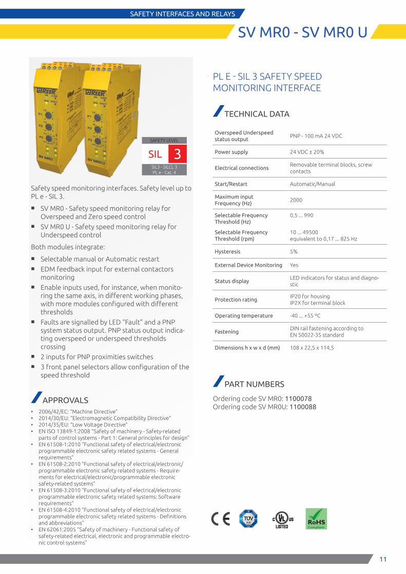
Safety speed monitoring interfaces. Safety level up to PL e - SIL 3.
■ SV MR0 - Safety speed monitoring relay for Overspeed and Zero speed control
■ SV MR0 U - Safety speed monitoring relay for Underspeed control
Both modules integrate:
■ Selectable manual or Automatic restart ■ EDM feedback input for external contactors
monitoring ■ Enable inputs used, for instance, when monito-
ring the same axis, in different working phases, with more modules configured with different thresholds
■ Faults are signalled by LED “Fault” and a PNP system status output. PNP status output indica-ting overspeed or underspeed thresholds crossing
■ 2 inputs for PNP proximities switches ■ 3 front panel selectors allow configuration of the
speed threshold
APPROVALS • 2006/42/EC: “Machine Directive” • 2014/30/EU: “Electromagnetic Compatibility Directive” • 2014/35/EU: “Low Voltage Directive” • EN ISO 13849-1:2008 “Safety of machinery - Safety-related
parts of control systems - Part 1: General principles for design” • EN 61508-1:2010 “Functional safety of electrical/electronic
programmable electronic safety related systems - General requirements”
• EN 61508-2:2010 “Functional safety of electrical/electronic/programmable electronic safety related systems - Require-ments for electrical/electronic/programmable electronic safety-related systems”
• EN 61508-3:2010 “Functional safety of electrical/electronic programmable electronic safety related systems: Software requirements”
• EN 61508-4:2010 “Functional safety of electrical/electronic programmable electronic safety related systems - Definitions and abbreviations”
• EN 62061:2005 “Safety of machinery - Functional safety of safety-related electrical, electronic and programmable electro-nic control systems”
PL E - SIL 3 SAFETY SPEED MONITORING INTERFACE
TECHNICAL DATA
Overspeed Underspeed status output
PNP - 100 mA 24 VDC
Power supply 24 VDC ± 20%
Electrical connectionsRemovable terminal blocks, screw contacts
Start/Restart Automatic/Manual
Maximum input Frequency (Hz)
2000
Selectable Frequency Threshold (Hz)
Selectable Frequency Threshold (rpm)
0,5 ... 990
10 ... 49500 equivalent to 0,17 ... 825 Hz
Hysteresis 5%
External Device Monitoring Yes
Status displayLED indicators for status and diagno-stic
Protection ratingIP20 for housing IP2X for terminal block
Operating temperature -40 ... +55 ºC
FasteningDIN rail fastening according to EN 50022-35 standard
Dimensions h x w x d (mm) 108 x 22,5 x 114,5
PART NUMBERS
Ordering code SV MR0: 1100078 Ordering code SV MR0U: 1100088
SAFETY LEVEL
SIL3 - SILCL 3PL e - Cat. 4
SIL 3

12
E S P E
SAFETY INTERFACES AND RELAYS
AD SR0 – AD SR0A
SAFETY RELAY MODULES FOR DEVICES WITH INTEGRATED FEEDBACK INPUT FOR EDM
TECHNICAL FEATURES
Safety relay outputs
AD SR0 2 NO + 1 NC - 2 A 250 VAC Each NO safety output line is inter-rupted twice by the two relays
AD SR0A 2 NO - 2 A 250 VAC
Response time (ms) ≤ 20
Power supply (VDC) 24 ± 20%
Electrical connections On terminal block
Operating temperature (°C) 0 ... 55
Protection ratingIP20 for housing IP2X for terminal block
FasteningDIN rail fastening according to EN 50022-35 standard
Dimensions h x w x d (mm) 101 x 35 x 120
PART NUMBERS
AD SR0 and AD SR0A module includes multi-language in-struction manual and CE declaration of conformity
Ordering code AD SR0: 1330902 Ordering code AD SR0 A: 1330903
Certi�ed byTÜV Rheinland
Product Safety GmbH
This product uses two guided con-tact safety relays manufactured by DOLD (type OA or OA 5643 5644) and certified by TUEV Rheinland.
Interface relay modules for safety light curtains with feedback input for EDM, such as EOS4 X, Admiral AX, EOS2 X, Vision VX/VXL/MXL and Janus.
■ Guided-contact safety relays ■ Additional NC contact line for the monitoring by
light curtain (EDM)
AD SR0 and AD SR0A modules can only be connected to safety sensors equipped with feedback input for monitoring external relays (EDM): EOS4 X, EOS2 X, Janus, Admiral AX (excluding AX BK models with Blanking), Pharo and Vision VX, VXL and MXL ranges.

13
NOTES
13

14
NOTES

15
CUSTOMER SERVICE
At ReeR we put our Customers always first
ReeR after sales service is committed to support all customers that need technical guidance regarding functionality, handling and installation of our products.
Customer Service Hotline +39 011 24 82 215
Monday to Friday 8.30 -12.30 and 13.30-18.00 (CET)
or contact [email protected]
For product returns please visit www.reersafety.com for further information.

Safety. Detection. Control.
ReeR SpA Via Carcano, 32 10153 Torino Italy T +39 011 248 2215F +39 011 859 867
www.reersafety.com | [email protected]
More than 50 years of quality and innovation
Founded in Turin (Italy) in 1959, ReeR distinguished itself for its strong commitment to innovation and technology.
A steady growth throughout the years allowed ReeR to become a point of reference in the safety automation industry at a worldwide level.
The Safety Division is in fact today a world leader in the development and manufacturing of safety optoelectronic sensors and controllers.
ReeR is ISO 9001, ISO 14001 and BS OHSAS 18001 certified.
Made in Italysince 1959
Issue 1
Rev. 0.0 October 2016 8946227 Interfaces Catalogue English Printed in Italy
ReeR SpA does not guarantee that product information in this catalogue are the most current available.ReeR SpA reserves the right to make changes to the products described without notice and assumes no liability as a result of their use or application. Our goal is to keep the information on this catalogue timely and accurate, however ReeR SpA accepts no responsibility or liability whatsoever with regard to the information on this catalogue. Reproduction is not authorised, except with the expressed permission of ReeR SpA.