safety notes. - adventures in watchmaking · safety notes. electrical. ... the user's...
TRANSCRIPT

SAFETY NOTES.
ELECTRICAL.
Wotorised Machines.
T h e machine must be connected to the mains supply via a standard 13A plug and socket. Fuse ratings are shown on the machine label.
When installing the machine follow the standard connection colour code for 13A plugs, ensuring that the earth wire (green or green/yellow) is connected correctly, AND that the socket to be used has a good earth connection back t o the Electricity Board's earth at the mains inlet t o the premises. If there is any doubt, consult your local Electricity Authority.
I f electrical maintenance is necessary, SWITCH OFF THE MACHINE AND DISCONNECT T H E MAINS PLUG BEFORE REMOVING ANY ELECTRICAL COMPARTMENT OR CONTROL BOX COVER.
REPLACE A L L COVERS BEFORE RECONNECTING TO THE MAINS SUPPLY.
Unmotorised Machines.
Apply the rules above t o your own installation and ensure that A L L electrical connections are covered t o prevent accidental contact.
Have your installation checked by a qualified electrician before putting into use.
OPERATING.
All machine operations including tool grinding present a hazard, particularly t o the operator's eyes. Swarf is sharp and hot, and it can be projected upwards as small, high velocity particles - th is occurs particularly when machining brass. Therefore:
ALWAYS WEAR PROTECTIVE GOGGLES WHEN USING MACHINES - DON'T TAKE CHANCES.
Rotating parts are also a hazard, therefore:
1. Ensure that all work pieces and cutting tools are correctly and adequately secured before commencing machining and at intervals during prolonged machining operations. 2. Don't make measurements while the work is rotating. 3. Don't judge the finish by running your fingers along a machined part whilst it is rotating. 4. Don't use hand tools such as files close t o the chuck.
THINK SAFETY.
WARNING
IF T I E S E MACHINES ARE TO BE USED I N INDUSTRY ADDITIONAL GUARDING MAY BE
REWIRED AS DEFINED I N THE FACTORIES ACT 1961 AND THE HEALTH AND SAFFX'Y
AT WRK ACT 1974.

THE COWELLS 90 LATHE
T h e Cowells 90 Lathe is a conventional , backgeared, screwcutting centre lathe.
T h i s Manual outlines its maintenance and operation and provides an introduction t o the Centre La the for the novice and is also applicable t o the 90 CW and 90 HS Lathes. The user's attention is directed t o the 'Cowells 90 Lathe Handbook' (code 10-260) which provides further and more detailed descriptions o f the machine and its application t o a wide range o f machining operations.
SECTION 1
MACHINE PARTS AND THEIR FUNCTIONS.
Movements.
All movements affecting the cutting tool positions, including drilling, etc., using the tailstock a r e controlled by feedscrews and graduated handwheels. Note that the CW Lathe tailstock is lever operated. A l l the feedscrews have a pitch o f I m m and the handwheels 4 0 divisions. Therefore, one ful l rotation o f the handwheel wil l produce a corresponding linear movement o f the associated slide of 1mm and a rotation o f one division wi l l produce a movement o f .025 mm (.001" approx.) NOTE : A l l feeds with the exception o f the cross slide are direct reading, i.e. the handwheel dial indicates directly the length turned on the depth o f the hole drilled. W i t h the cross slide, however, the handwheel dial indicates the depth o f cut, BUT, if the toe l is moved inwards one division LO25 mm) the diameter o f the work wil l be reduced by MI ICE t h a t amount (.05 mm). THIS IMPORTANT FACTOR MUST BE REMEMBERED WHEN TURNING DIAMETERS.
T w o additional 'preset' movements are provided at the Compound Slide and Tailstock t o facilitate angle and taper turning.
Compound Slide.
The Compound Slide operates on a rotatable base secured to the cross slide b y two angle pins and screws, thus allowing the slide t o be set at various angles t o the lathe axis for taper and angle turning.
To set the compound slide angle, slacken the two screws on the side faces o f the cross slide immediately under the compound slide. The compound slide can then be rotated t o the required angle using the angular scale o n the cross slide face. Tighten the screws. NOTE: Some accessories are attached t o the cross slide using the compound slide mounting hole. For these accessories t o be used the compound slide and its base must be removed as a complete unit.
To remove the compound slide assembly, remove the two screws t o allow the angle pins t o move outwards. Then, rotate the uni t back and forth, pulling upwards t o push the pins clear. Note that the assembly is a tight fit and some force is required t o remove it.
Tailstock Set Over.
The tailstock centre can be moved out o f alignment wi th the lathe centre line t o enable taper turning to be carried out. The total movement is limited t o 6mm and this method o f taper turning is normally restricted t o very small angles. T o set the tailstock over:
a) Release the clamp lever at the rear o f the tailstock body. b) Using the two screws (one at the front, and one at the back o f the tailstock body) move the body sideways o n its base alternately slackening one screw and tightening the other un t i l the desired amount o f set over, in the desired direction, is obtained. The tailstock can then be used i n the normal way except that the parts turned wi l l have a taper i n diameter equal t o twice the amount o f set over. To set the tailstock back t o its centre position repeat the operations in (a) and (b) bu t i n
2

t h e reverse direction, using a test bar and dial test indicator t o obtain accurate alignment. Alternatively, alignment can be set by turning the ends of a bar between centres t o check t h e setting. The setting is correct when the diameter obtained at each end o f the bar is the same FOR THE SAME TOOL SETTING.
D r i v e Systems.
1. CW AND HS LATHES Single pulley and thyristor speed controller.
2 . 9 0 LATHE T h e headstock spindle is driven by a conventional 3 step pulley arrangement f rom a counter- sha f t powered by the motor. Belt tensioning is achieved by means o f a cam operating on a cam follower screw which projects through the countershaft bracket. Pulling the cam lever forward releases the belt tension thus enabling the various steps o f the pulley system t o be selected. Pushing the lever back tensions the belt.
Backgear. -- T h e backgear is a device used t o extend the speed range o f the headstock spindle by introducing gearing between the driven pulley and the spindle. W i t h the 3 step pulley, 6 speeds can be selected as follows:
a) Unqeared. Disengage the backgear by releasing the grubscrew in the top face at the rear o f the headstock casting. Push the lever on the backgear eccentric back unt i l the gears are disengaged. Tighten t h e screw. Secure the 3 step pulley t o the spindle by tightening the grubscrew in the centre 'Vee' o f the pulley. The machine is now in direct drive and the 3 speeds available are 880, 5 0 0 and 280 r.p.m. NOTE: These speeds apply t o 50 Hz machines. For 60 Hz machines the speeds w i l l be approximately 20% higher.
b) Geared.
Reverse the procedure in (a) t o engage the backgear ensuring that there is a small amount o f clearance between the gear teeth. Never run gears t ightly meshed. Remember t o secure the backgear eccentric locking screw and release the pulley locking screw. The machine is now in geared drive and the speeds at the pulley are reduced b y a ratio o f 4.6 t o 1 giving 180, 107 and 60 r.p.m. at the spindle (50 Hz machine).
A u t o Traverse and Clutch. (90 Lathe only).
A u t o traverse provides a means o f moving the cutting tool along the axis o f the lathe t o perform turning operations automatically. It is achieved by driving the leadscrew through a series o f gears driven from the headstock spindle, the rate of movement (feed) being determined by the gear ratio and the pitch o f the leadscrew. Note that 'feed' is the term used t o express the movement along the axis for each revolution o f the workpiece and is constant for any given gear ratio regardless o f spindle speed. The gearing fitted for the auto traverse provides a feed of .07mm (.003") approx. The direction o f traverse is controlled by the total number o f gears in the 'train' which is arranged t o give movement t o the left o r right. Movement t o the left (toward the headstock) is normal. The gears are f i t ted t o a slotted plate clamped to a boss at the headstock end o f the lathe. The slot in the plate allows for variations in gear centres iflwhen the ratio is changed, and t he whole plate, complete wi th gears, may be rotated around its mounting boss t o engage t he driving gear on the tailend of the headstock spindle. As with al l gears, leave a small clearance between the teeth when setting. The leadscrew is connected t o the gear system through a clutch operated by the lever at the front o f the headstock. Moving the lever t o the lef t disengages the drive, t o the right engages the drive. A t r ip bar is provided t o disengage the clutch automatically as the too l approaches the head- stock. The t r ip is in the form o f a slotted bar mounted on the 'apron' a t the front of the saddle, the slot allowing for adjustment of the precise point o f trip. For instance, the trip
3
can be set to disengage the clutch when the cutting tool is about 118" from the chuck jaws. Then long turning operations can be performed automatically, each successive cut stopping at the same point without the risk of the tool or chuck being damaged should the operator's attention be elsewhere.
Screwcutting: (90 Lathe Only)
The system of driving the leadscrew through a train of gears is also used for screw cutting. For this the gears are selected from the range provided in accessory set 10-206 together with those provided with the auto-traverse, to give the required rate of movement, but in this case the feed is equal to the pitch of the thread to be cut. When screwcutting, the clutch is NOT disengaged at the end of each cut. The machine MUST BE STOPPED, THE TOOL WITHDRAWN AND TRAVERSED BACK TO THE START OF THE THREAD USING THE MOTOR REVERSE. The tool is then set back to i t s previous position plus the amount for the next cut and the operation repeated until the required depth of thread is achieved.
SECTION 2
CARE OF THE MACHINE.
Lubrication.
Oiling points are provided for the headstock and leadscrew bearings. All other working surfaces such as slides, feedscrews, gears etc., are lubricated by applying oil directly to the surface. Use a good quality SAE 20 or 30 grade of machine oil such as Myford NUTB, for a l l lubrication. Do not use 'sewing machine' type oils of the 3 in 1 kind. These are for light duty only and are not suitable for the Cowells machine. Frequency of lubrication is dependent upon the duty of the machine but: (a) Always lubricate before use and after cleaning down. (b) During prolonged machining operations lubricate at regular intervals paying particular
attention to the headstock oil cups.
Adjustment. - 1. Gib Strip2 Gib strips are steel inserts fitted between the faces of sliding parts to provide accurate control of the f i t of the parts, thus allowing for initial setting and compensation for wear. They are positioned and secured by means of screws and locknuts and are used on the compound slide, cross slide and saddle. To adjust any of the gib strips, slacken the appropriate locknuts and then set each screw in turn to achieve a good slide action, without sideplay and without undue loading of the feedscrew. Tighten the locknut as each screw is set to ensure that there will be no further movement when the effect of the setting is checked. Readjust each screw if necessary t o achieve a good slide action for the whole of the travel.
2. Feedscrew Backlash. Feedscrew backlash is controlled by the position of the handwheel on the feedscrew extension. To adjust, slacken the screw in the side of the handwheel and then turn the slotted screw in the front of the handwheel clockwise until the backlash is 5 divisions or less of the graduations. Tighten the screw in the side of the handwheel. Note that it is impossible to eliminate backlash completely and that any backlash is always accounted for when performing machining operations.
3. Headstock Spindle Bearings (90 Lathe).
HS Lathe has sealed ball bearings, no adjustment. CW Lathe has taper cone bearings. Adjustment is provided at the rear cone.
90 Lathe adjustment is provided by means of split caps and screws. To adjust, top up the bearing cups with the correct oil, set the bzlt to give the highest speed (880 r.p.m.) and switch the machine on. After a few minutes, switch off and release the belt tension. Turn the bearing cap screws very slowly and a fraction of a turn a t a time, clockwise to tighten the bearing whilst rotating the spindle back and forth by hand. The correct setting i s when the screws are as far clockwise as they can be set without there being any drag on the spindle.

4. Headstock Spindle End Float. I f end float adjustment is necessary, slacken the grubscrew securing the large gearwheel t o t h e spindle at the end of the headstock. Turn the screw collar immediately behind the gear clockwise (viewed from the rear) t o reduce end float. Tighten the gear wheel securing screw. T h e setting should be sufficient t o remove end float only; there should be no loading o f the bearing faces.
5. Belt Tension. If adjustment of the belt (or belts) tension becomes necessary, proceed as follows: a) Position the belt on the centre step o f the 3 step pulley. b) Slacken the locknut on the cam follower screw at the rear o f the countershaft bracket (on the 10-200B also slacken the two screws o n the right hand face o f the motor compartment.) c) Set the cam lever t o the tensioned position and adjust the cam follower screw t o obtain the correct belt tension; tighten the locknut. d) 10-2008 only. After (c) above, push down on the screw in the slot in the motor compart- ment, (b) above, t o tension the motor drive belt. Tighten both screws on the right hand face of the motor compartment. T h e setting is now correct for all 3 steps of the spindle pulley. C W and HS Lathe belts are tensioned b y adjusting the motor position.
General Rules.
1. Pay attention t o lubrication at all times. 2. Keep working surfaces clear of swarf as much as possible. Swarf is abrasive and in some cases can absorb oil, resulting in 'drying out' o f a previously lubricated surface. 3. Always clean the machine, re-oil after use, particularly if water soluble oils or paraffin have been used as cutting lubricants. These products can cause rust. 4. Do not use abrasive fluids (metal polish etc.,) t o clean the machine. Remove any swarf w i t h a soft brush - wipe with a clean dry cloth and re-oil. 5. Never leave the machine unused for long periods w i th the belts tensioned. Always release t h e belt tension at the end o f working period.
NOTE : These rules should also be applied t o machine accessories.
SECTION 3
OPERATING THE MACHINE
WORK HOLDING AND SUPPORT
Centres Rotating Centre
Between Centres.
This is the simplest method of work holding and consists o f drilling a centre hole using a centre drill, in each end o f the material. These are then used t o support the material on the

centres in the headstock and tailstock. Note that the hard centre is fitted t o the tailstock a n d the soft centre t o the headstock. Rotary motion is imparted by means o f a 'carrier' or 'dog' which is clamped t o the work at the headstock end and is driven by a peg f i t ted t o t h e faceplate. Note that the tailstock centre must be kept well lubricated and that, as turning progresses, the heat generated wil l cause the work t o expand. This necessitates readjusting t h e tailstock centre at intervals t o compensate for the expansion.
F o u r Jaw Chucks.
Independent 4 Jaw Chuck
This is the most versatile type o f chuck. It is possible t o hold irregular shaped articles, such as castings and square bar and give absolute accuracy when holding round work. The Jaws can be reversed t o hold large objects, or just one or two can be reversed and the others left in their normal position when, for instance, rectangular objects need t o be held. To reverse t h e jaws, withdraw them completely and remove the screw from its recessed tongue seating on the jaw. Turn the jaw over, refit t o the screw and replace the chuck. The method o f setting the chuck is t o open each jaw in turn unti l the work wil l enter. Now tighten each j a w equally. Rotate the chuck by hand; any major error i n t ru th wi l l be very obvious and can be corrected by loosening the jaw on the low side as near as can be estimated b y the half error. The opposite jaw is then tightened to take up the slack. Note that it may be necessary to loosen the other jaws slightly t o enable the workpiece t o move. The final setting is done using a dial test indicator. There are many indicators on the market and we suggest that a low cost type such as the Verdict Junior is obtained. They are very robust and o f a size easily managed on the Lathe. To use : Fi t the indicator i n the toolpost using a bar t o hold it in a convenient position. Set t h e stylus o f the indicator against the work t o a point where the hand registers a mid point on the scale. Now, by turning the chuck unt i l one o f the jaws is directly i n line with the stylus, note the reading o f the dial. Without altering the position o f the indicator turn the chuck unt i l the jaw opposite the one just checked is i n line with the stylus; the dial wi l l indicate error. This can be corrected by loosening one jaw, the low reading one, and tightening the high reading one unti l the readings are the same for both jaw positions. Turn your attention to the other jaws and repeat the process until the work runs true. It takes practice t o use the 4 Jaw chuck t o the best advantage, bu t once you have gained the ski l l i n adjusting the jaws, it takes very l i t t le t ime t o set a job in it.
The Three Jaw Self Centering Chuck. This is useful for holding round and hexagonal material. It is quick and easy t o operate and is favoured by many users. Its main disadvantage is that it is rarely accurate, and error of 0.075mm (.003") is usual, even when new, and the error can vary on different diameters o f workpieces. This does no t detract f rom the usefulness o f this accessory as long as the user is aware o f i ts limitations. A l l 3 jaw chucks can be used as 'outside' jaw o r 'inside' jaw chucks. This is achieved on larger chucks b y having two sets o f jaws. On the Cowells chuck Part No. 10-208 changing f rom one mode to the other is done by removing the slotted screw i n the centre o f each jaw, reversing
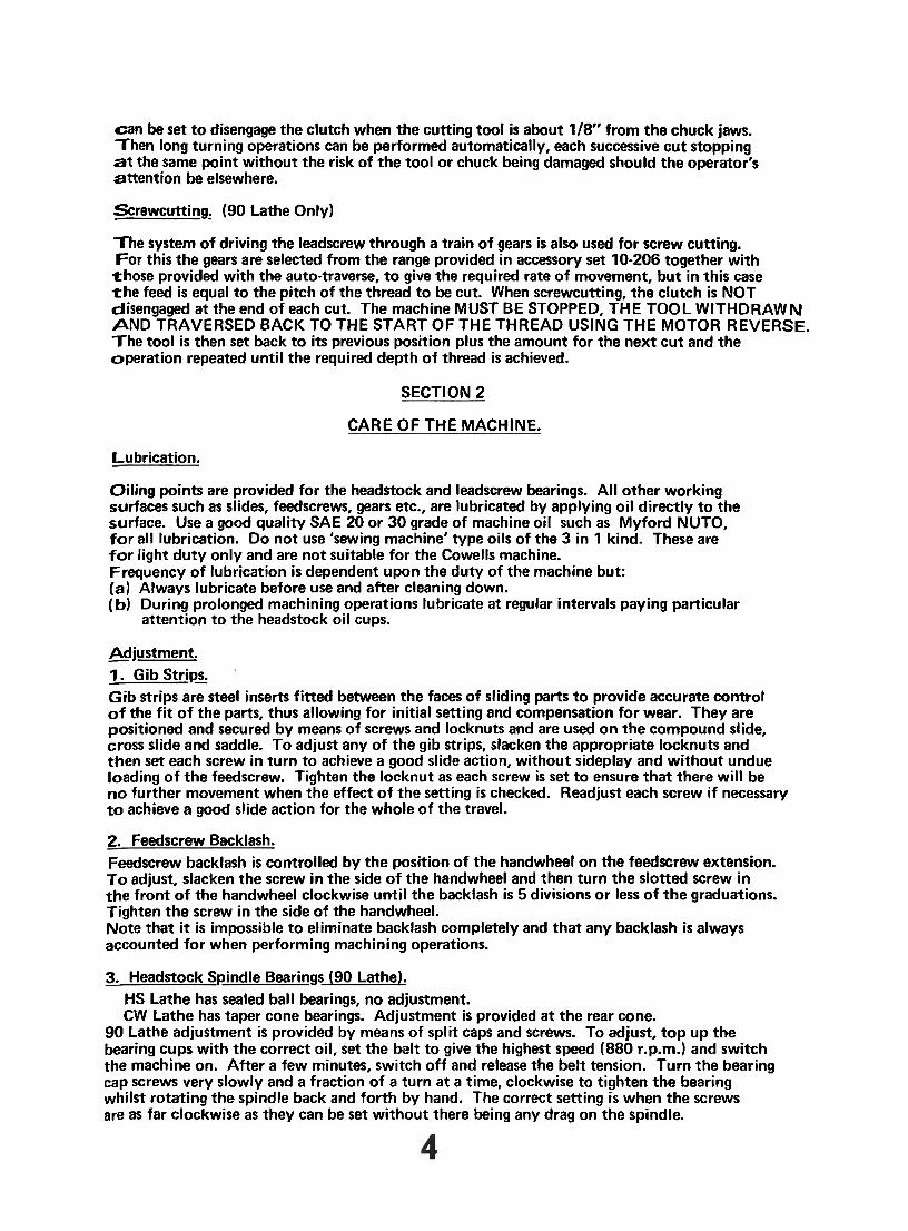
t h e jaws on their carriers and securing them with the screws.
3 Jaw Scroll Chuck Cowells 3 Jaw Scroll Chuck
Other chucks have jaws which can be reversed. In this case when the jaws have been completely removed, rotate the scroll unt i l the thread is in position t o engage the teeth o f the jaw No.1. in slot No.1. N o t e that the jaws are used in the same slots, i.e. No.1. in slot No.1. and so on. If this sequence is not followed the jaws wi l l not run true.
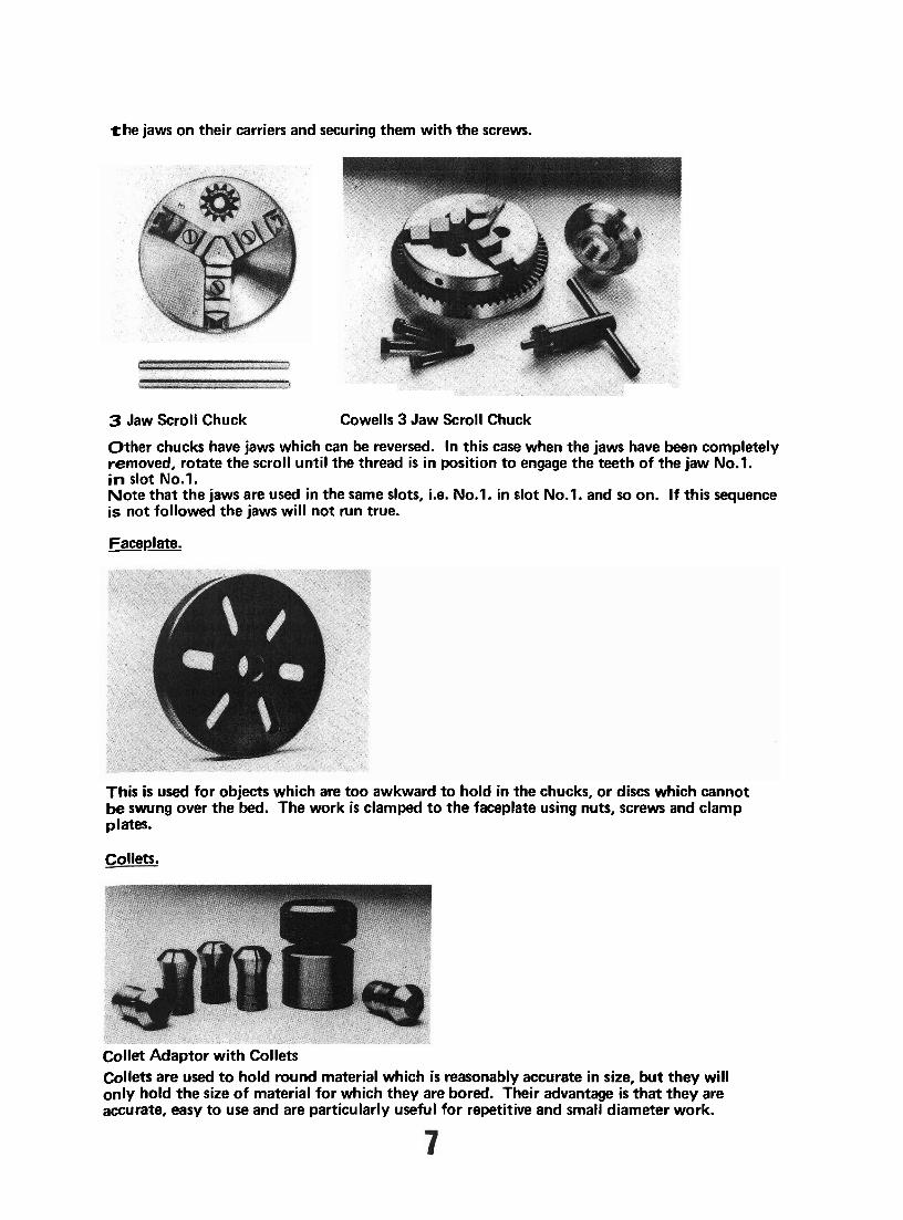
Faceplate. --
This is used for objects which are too awkward t o hold in the chucks, or discs which cannot be swung over the bed. The work is clamped t o the faceplate using nuts, screws and clamp plates.
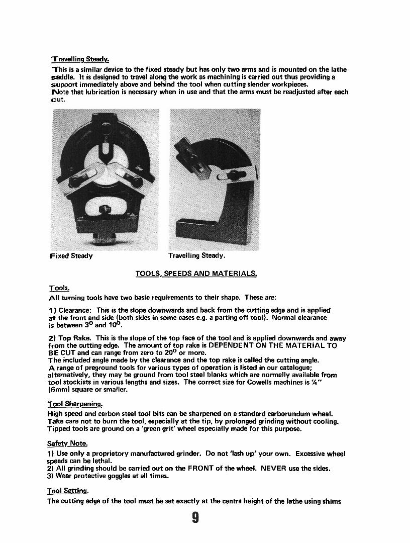
Collets.
Collet Adaptor w i th Collets Collets are used t o hold round material which is reasonably accurate in size, but they wi l l only hold the size o f material for which they are bored. Their advantage is that they are accurate, easy t o use and are particularly useful for repetitive and small diameter work.

Maintain scrupulous cleanliness at all times wi th collets. Wipe the nose socket clean of chips a n d swarf before inserting the collet. D o no t tighten unt i l you have pushed the material into t h e collet. Atways wipe the material clean and check that there are no burrs marring the surface as any defects can result i n inaccuracy. B lank collets are available which users can finish t o their own requirements.
W o r k Holdina on the Cross Slide. So far, the methods o f work holding have been concerned with turning, that is, the technique where the work is rotated and the tool is moved along or across it.
Angle Plate
Vertical Mill ing Slide
Machine Vice
The alternative t o this is t o have the work clamped t o the cross slide by means o f various accessories, then carrying out the machining operation by traversing the work across o r along a rotating cutter. This method is used for mill ing on the lathe, the mill ing cutter being held i n a chuck. Note that for mill ing it is normal t o use a vertical slide mounted o n the cross slide t o give the 3rd axis o f movement necessary for this operation, the work being clamped t o the vertical slide.
Fixed (3 Point) Steady, --- This is a device having 3 arms which are used t o support long workpieces whilst machining operations are performed o n the free end. It is f i t ted i n the lathe bed slot and is used b y adjusting the bearing arms t o the diameter o f the work (this is best done wi th the work held in a chuck and the steady positioned as close to the chuck as possible). After setting, it can be moved t o the required position t o support the work and clamped i n the slot in the lathe bed. Note that the bearing arms must be kept lubricated when in use.
Travelling Steady.
Th i s is a similar device t o the fixed steady bu t has only two arms and is mounted o n the lathe saddle. It is designed t o travel along the work as machining is carried ou t thus providing a support immediately above and behind the too l when cutting slender workpieces. N o t e that lubrication is necessary when in use and that the arms must be readjusted after each cu t .
Fixed Steady Travelling Steady.
TOOLS, SPEEDS A N D MATERIALS.
Tools. - All turning tools have two basic requirements t o their shape. These are:
1 ) Clearance: This is the slope downwards and back from the cutting edge and is applied at the f ront and side (both sides i n some cases e.g. a parting of f tool). Normal clearance is between 3 O and 1 OO.
2) Top Rake. This is the slope o f the top face o f the too l and is applied downwards and away f rom the cutting edge. The amount o f top rake is DEPENDENT ON THE MATERIAL T O BE CUT and can range from zero t o 20' or more. The included angle made by the clearance and the top rake is called the cutting angle. A range o f preground tools for various types o f operation is listed i n our catalogue; alternatively, they may be ground from tool steel blanks which are normally available f rom too l stockists i n various lengths and sizes. The correct size for Cowells machines is %'* (fjmm) square or smaller.
Tool Sharpening. High speed and carbon steel tool bits can be sharpened on a standard carborundum wheel. Take care no t t o burn the tool, especially a t the tip, b y prolonged grinding without cooling. Tipped tools are ground on a 'green grit' wheel especially made for this purpose.
Safety Note. 1) Use only a proprietory manufactured grinder. D o no t 'lash up' your own. Excessive wheel speeds can be lethal. 2) Al l grinding should be carried ou t o n the FRONT o f the wheel. NEVER use the sides. 3) Wear protective goggles at all times.
Tool Setting, The cutt ing edge of the too l must be set exactly a t the centre height o f the lathe using shims

i f necessary to achieve the correct height and must be firmly clamped with a minimum over- hang to prevent deflection due to the cutting load. The position of the tool relative to the lathe axis is dependent on the type of tool to be used and the work to be done. Normally the tool is fixed at 90° to the lathe axis but this can be varied to suit particular requirement, e.g. when facing.
Speeds. -- The cutting speed for a given material is the speed a t which the surface being cut passes the tool and is expressed in feet per minute. From this it can be seen that for a given material cutting speed, as the diameter increases the lathe speed (RPM) must be decreased and conversely as the diameter decreases the RPM must be increased. I n theory this requires an infinitely variable control of spindle speed without the loss of torque a t low speeds. This is not normally available on small lathes which are generally provided with stepped speeds. In practice therefore it is necessary to compromise and select the nearest speed (preferably lower) to the ideal speed and generally speeds can be described as 'slow', 'medium' or 'fast', some variation being allowable around these terms because of the relationship between the type of material and i t s diameter. When in doubt start with a low speed and work up.
Applications. - - Cast Iron. 1 ) Slow Speed. 2 ) No top rake on tool (preferably use a tungsten carbide tipped tool). 3 ) Do not use a cutting lubricant.
Mild Steel. 1 ) Medium speeds. 2 ) Medium to large top rake on tool. 3 ) Use cutting lubricant.
Brass. - 1 ) High speeds. 2) No top rake on tool. 3) Do not use cutting lubricant.
Bronze. 1 ) Medium to high speeds. 2) Top rake on tool, depending on copper content. 3 ) Cutting lubricant may be required depending on copper content.
Light Alloys. --- 1 ) High speeds. 2) Large top rake on tool. 3 ) Use paraffin as cutting lubricant.
Castings. - - All castings have a hard skin and it is recommended that the first cuts are made with a tipped tool at a slow speed. When the skin has been removed normal speeds and tools for the material can be applied.
General Notes on Turning, 1) Feed the tool along the work smoothly using both hands. Variations in feed will be evident as rings around the work.

2) Use the appropriate cutting lubricant wherever possible. This will produce a better finish and prolong the tool life.
3) Wherever possible avoid using sharp pointed tools for turning and facing, the point disappears very quickly giving a rough finish to the work. A tool with a small radius has a longer l i fe and produces a better finish. 4) Chatter. This is a phenomenon which occurs in machines and is a function of their natural resonance. There will be no doubt when it occurs. There will be significant vibration accompanied by noise and the surface of the work will be very rough almost to the extent o f having 'flats' on it. Once chatter has started on a workpiece it is extremely difficult to overcome. The normal cause of chatter and points to check are:-
1 ) Too much overhang on the work or tool (or both).
2) Too high a speed.
3) Too much of the tool edge in contact with the work. 4) Work not clamped securely. Chatter is much more easily overcome by checking the possible existence of these causes BEFORE starting machining.
Other Machiningsperations.
Drilling, -
1/4" Drill Chuck and Key
Drilling (along the axis of the lathe) can be carried out in three ways using a drill chuck mounted on a suitable arbor (see accessory list). The normal method is to f i t the drill chuck in the tailstock whilst the work is held in a chuck etc. and rotated; the tailstock feedscrew or lever being used to feed in the drill. Alternatively t h e drill chuck can be held in the headstock and rotated whilst the work is clamped to the cross slide, the lead screw being used BY HAND to feed the work. This technique can also be used with a tailstock drilling pad where the work is held against a pad (plain or vee) fitted in the tailstock; the feed being imparted by the tailstock feedscrew or lever. When drilling always start the hole with a centre drill and, during drilling, withdraw the drill partially from time to time to clear the swarf. Large diameter holes may need 'piloting' that is, drilling a small hole first and then following with the larger drill.

Thread Cutting,
D i e Holders
B u t t o n Dies. B u t t o n Dies are used extensively t o cu t external threads. They are used o n the Lathe in a ho lder which consists o f a body which is bored through t o a sliding fit o n the tailstock barrel; the end o f the body being recessed t o take standard but ton dies. The holders are available in the sizes (Cat. No. 10-226, 10-227, 10-228) t o accept dies o f 13/16", 1" and I 5/16" dia: T o use:- 1) F i t the d ie i n the dieholder recess, securing it w i th the 3 screws f i t ted t o the holder. Note t h a t the centre screw engages the spl i t in the die and is used to set the thread diameter by varying the gap. 2) Extend the tailstock barrel 20-25mm and slide the dieholder onto the barrel. 3) Feed the dieholder to the work, rotat ing the spindle BY H A N D t o cut the thread. Use a cu t t i ng lubricant. When threading i n this way it is essential t o break o f f the swarf chips by ro ta t ing a fraction o f a turn back for each full tu rn forward. A f t e r completing the cutt ing remove the die b y rotating the spindle BY H A N D in the reverse direction. D O N O T drive the die o f f under power.
G P P ~ ~ : Holes can be threaded b y using the appropriate tap held in a drill chuck f i t ted to the tailstock. A s w i t h dies, the complete operation is carried o u t by hand, again rotating back a fract ion fo r each turn t o break o f f the swarf chips. N o t e tha t when tapping, the tailstock is l e f t free to slide along the lathe bed. Feeding is by hand pressure on ly behind the taibtock.
Screwcutting (90 Lathe only). Both external and internal threads can be c u t using a single po in t t oo l as br ief ly described in the section o n Auto Traverse and Clutch. However, although this is a simple process in principle it should be regarded as a more advanced turning skil l and is therefore considered to be outside the scope o f these notes. T h e user's attention is n o w directed t o the 'Cowells 90 Lathe Handbook' which deals in depth with this subject and the further application o f specialised accessories and techniques.

SECTION 4.
TURNING EXERCISE
For the purpose of the exercise assume that a piece of 19mm (34") Dia. mild steel bar, 25mm ( 1 ") long, must have i ts diameter reduced to % '" at one end for a length of 10 mm., the turned diameter. Procedure.
1. Fit the 4 jaw chuck to the lathe - set the bar in the chuck with W" projecting outside the jaws - adjust the jaws so that the work runs true, using the technique outlined in the description o f the 4 jaw chuck. 2. Fit a side turning tool similar to (No.7. from set No. 10-230A or No.4. from set No. 10-230) in the tool holder slot nearest the chuck so that the cutting edge is exactly at the lathe centre height and a t 90° to the lathe axis using shims if necessary to obtain the correct height setting. Clamp the tool securely. 3. Select the lowest of the ungeared speeds (280 r.p.m.), that is, the drive belt must be on the largest diameter pulley vee on the headstock spindle. DO NOT SWITCH ON.
4. Using the leadscrew and cross slide hand wheels, set the tool position so that it just touches t h e end of the work. Note the reading on the leadscrew dial. Using the cross slide hand wheel, move the tool back to clear the bar diameter and then towards the chuck, turning the leadscrew 10 FULL TURNS from the reading noted. Move the tool in until it just touches the bar and turn the spindle BY HAND one revolution. You will now have a line scribed around the bar exactly 10mm from the end; this can be used as a guide to the finished length when turning. 5. Move the tdol dear of the work back towards the end of the bar. Switch on. (Note that t h e direction of rotation is anticlockwise looking a t the chuck jaws). 6. Move the tool in to just touch the bar and then move it to just clear the end. Note that from this point on the tool will only be moved INTO the work using the cross slide hand wheel, thus accounting for backlash, and that the cutting movement is obtained by use of t h e leadscrew handwheel. 7. Set the tool 0.25 mm (%turn) in and take one cut along the bar, stopping just short of the scribed line. Feed the tool slowly and evenly, using BOTH hands, when cutting. Move the tool back to the end of the bar and then take a second cut of 0.25 mm. Switch the machine OFF, and move the tool back to the end of the bar. Note that switching off before moving the tool stops any tendency to cut on the return movement. This practice should be followed at any measurement stage and when finishing. 8. Using a micrometer, measure the diameter of the turned length. Assuming that the diameter is 36" (.7508') and that you are using a 0-1 " micrometer, the reading obtained should be .75OV -....
minus the material removed. 2 cuts of 0.25 mm (.020" total) will have reduced the diameter by 0.040", therefore the reading shou Id be ,710" approx. Let us say the reading is .710". Then, the amount of material s t i l l to be removed is .710" - .500" (the required diameter) = .219" but remember that the tool only has to be moved in by HALF the amount, therefore a further .105" has to be set on the cross slide handwheel to bring the bar to the finished size. This can be done by using say 4 cuts of .020" (.5 mm) = .080M, followed by a check measurement, then a cut of .008" (.2 mm) followed by a check measurement. At this stage you will be close to the required diameter and a further reduced depth of cut can be made to leave a final cut of approximately ,003". This finishing cut should be made as slowly and evenly as possible. Move the tool BACK from the work at the end of this cut and switch the machine off. Note that each cut should be 10 mm long, that is, to the leadscrew dial reading obtained when scribing the mark in 4 above. 9. The turning exercise is now complete and the turned portion will be %" diameter, 10 mm long and concentric with the 36" diameter. I f you wished, you could now carry on and practise drilling and tapping on the same workpiece. I f this is done without disturbing the bar in the chuck, the hole will also be concentric with the diameters. The principles used throughout the exercise are the basis of all machining operations and can be applied to any work.

Wheel and pinion cutter Mounting; and maintainance
I , SECURING OF MOTORISED COUNTERSHAFT TO LATHE BASE: TWO M6 TAPPED HOLES ARE PROVIDED IN THE REAR SURFACI: TABI.1, AREA OF THE LATHE BASE.THE TWO FIXING BOLTS ARE SUPP1,IED. REMOVE THE KNURLED ADJUSTER, SPRING AND SEATING WASHERS FROM THE WHEEL AND PINION MOTOR MOUNTING PLATES. COUNTERBORED SLOTS WILL BE SEEN IN THE BOTT'OM PLATE. THE UNIT MAY THEN BE BOLTED TO THE REAR SURFACE TABLE ARI:I-\ IN THE DESIRED POSITION. 2, MOUNTING OF THE VERTICAL MILLING SLIDE: THE SLIDE SHOULD BE SECURED INTO THE TWO REAR MOST TEE S1,OTS OF THE LATHE CROSSLIDE WITH ITS TABLE FACING THE LATHE I-IEADSTOCK,ENSURE CLEARANCE FOR ITS TABLE TO MOVE VERTICALLY. TO ENSURE THAT THE 'TABLE IS S ~ U A R E TO THE LATHE HEADSTO(:I< 1.1. IS ADVISED THAT THIS BE L ~ ~ ~ ~ ~ ~ ~ ' SQUARE USING A DIAL ' rn-r ' INDICATOR. 3, MOUNTING OF THE MILLING SPINDLE HEAD: THE MILLING SPINDLE HEAD MAY BE MOUNTED IN A VARIETY O F POSITIONS IJPON THE VERTICAL MILLING SLIDE DEPENDING ON TI-113 WORK UNDERTAKEN. ATTACH THE SPINDLE HEAD TO THE SLIDE BEFORE HOOKING UP TI-11.1 TOOTHED BELT DR1VE.A LOCATING TENON IS PROVIDED ON I'HE MILLING HEAD BODY AND TWO M5 CAI' 1HEAD SREWS AND 'T13E NU'I'S TO SECURE IT IN PLACE. IT WILL BE NOTED THAT THE CARTRIDGE HOLDING THE MILLING SPINDLE MAY BE REMOVED.THIS IS TO ALLOW THE MILLING HEAD BODY TO BE INVERTED AND THERBY GAIN EXTRA HElGHT ABOVE THE WORKPIECE.ONE M5 CAP HEAD SCREW LOCKS THE CARTRIDGE IN PI-ACE. A LUBRICATION HOLE WILL BE SEEN IN THE CARTRIDGE BODY.I'KOI?l 'TIME TO TIME THE CARTRIDGE SHOULD BE REMOVED OR SLID BACK SO AS TO ALLOW A FEW PUMPS OF OIL.IT IS NOT POSSIBLE TO OVER 011 TI-IIS CARTRIDGE, SO PUMP TI-IE OIL, CAN ~m- TI, OIL SEEPS FROI\/I 'rFII: LUBRICATION HOLE.. 4,TENSIONING AND POSITIONING OF TI-IE TOOTH BELT IIRIVE: THE TOOTHED DRIVE BELT BETWEEN MILLING HEAD AND MOTORISED LAYSHAFT SHOULD BE TENSIONED VIA THE KNURLED SPRING ADJUSTER.DO NOT BE TEMPTED TO OVERTIGHTEN THIS ADJUSTER AS UNDUE TENSION WILL BE EXERTED ON THE LATHE SLIDEWAYS MAKING THEM STIFF TO 0PERATE.IT IS ONLY NECESSARY TO TIGH1"EN UNTIL ANY TENDENCY TO BOUNCE IS ELIMINATED.CORREC1' TENSIONING WILL SOON BECOME APPARENT WITH USE. THE TOOTHED BELT DRIVE SHOULD RUN IN A VERTICAL POSITION AUT0MATICALLY;BUT IT MAY BE NECESSARY TO MOVE THE BOTl'OM I'ULLEY (WITH MOTOR STATIONARY) INTO THE CORRECT POSITTOU.

5, TENSIONING OF THE VEE BELT DRIVE THE VEE BELT DRIVE BETWEEN 3 S'I'EP MOTOR PlJLLEY IIND LA)'S]j/\!:'l. PULLEY MAY AFTER SOME TIME REQUIRE ADJUSTMEN'I'. IT WILL BE NOTED THAT THE MOTOR HAS A MOUNTING CRADLE W1'1'114 X M5 HEX. BOLTS.THE CRADLE ITSELF HAS TWO RUBBER MOUN'I'S BENEATH IT.IT IS POSSIBLE TO FINE TUNE THE ADJUSTMENT OF THE BELT BY TIGHTENING OR LOOSENING THE HEX. BOLTS. SHOULD THIS PROVE INSUFFICIENT,IT WILL BE NECESSARY TO MOVE THE MOTOR BACK. 6, SLOW SPEED MOTOR PULLEY PIJLLEYS ARE SECURED TO THE END OF THE MILLING SPINIlLl3 \'IA TWO GRUB SCREWS A?' 120 DEGREES APART.THE MILLING SPIND1,E IS HARDENED THROUGHOUT SO NO DAMAGE TO THE SPINDLE CAN OCCUR. 7, MILLING SPINDLE BEARING ADJUSTMENT IF END FLOAT CAN BE DETECTED BETWEEN THE MILLING SPINDLE c\VD ITS BEARINGSJT WILL BE NECESSARY TO ADJUST THE SPLIT NU?' ADJUSTER.DO NOT OVERTIGHTEN THE SPLIT NUT ADJUSTER; THE SPINDLE SHOULD REVOLVE FREELY WITHOUT END PLAY.UNtIOOK 'fl-IE TOOTHED DRIVE BELT TO VERIFY THIS. 8, FITTING THE DIVISION PLATE,DETENT AND ADAP'rOII TO THE 90ME LATHE. TO FIT THE ABOVE ON THE 90ME LATHE IT WILL BE NECESSARY TO REMOVE THE LATHE'S GEAR TRAIN. 1 . REMOVE THE COLLAR HOLDING ON THE LARGE 64 TOOTH (;EAR 11 1- THE BOTTOM OF THE ?'RAIN. 2,SLACKEN THE M5 CAP HEAD SCREW OF THE GEAR CARRIER PI-AT!: WITHDRAW THE 64 TOOTH GEAR ALONG WITH THE COMPLETE C;E.AI< TRAIN.NOTE THAT IT IS NOT NECESSARY TO DISTURB THE SETI'INGS 0 1 ' THE TWO DOUBLE GEARS ON THE TRAIN. 3, REMOVE THE KNURLED LOCKNUT FROM ?'ME LATHE HEADSI'OCK SPINDLE,20 TOOTH GEAR (BE CAREFUL NOT TO LOOSE THE TINY KEY BENEATH THE 20 TOOTH GEAR), AND TI-IE IZOUND BEARING ADJIJ3 FER NUT.DO NOT REMOVE THE 64TOOTH SPINDLE GEAR,IT IS NOT _NECESSARY TO DISTURB ITS SETTING. 4, THE DIVISION PLATE ADAPTOR WILL NOW SCREW N T O PLACE.I1' CAN THEN BE LOCKED IN PLACE VIA THE GRUB SCREW,BENEA'I'H WHICH IS A BRASS PAD SO AS NOT TO DAMAGE THE SPINDLE TI--IREf\I). 5, THE DETENT MECHANISM MOUNTS IN THE SAME MANNER AS THl. GEAR TRAIN PLATE. 9, LUBRICATION THE LAYSHAFT SPINDLE RUNS IN OILITE BUSHES IMPKEGNAI'E~~l> M I 1-14 OIL. HOWEVER, IT IS ADVISABLE 'rO LET A l,ITTL.E 011. INTO .THI:SI, BIJSHES FROM TIME TO TIME.NO OILERS ARE PROVIDED,BUI' THE OIL. WILL INGRESS IF THE ENDS OF THE LAYSI-IAFT ARE LUBRICA'TED. ALWAYS KEEP THE LUBRICATION HOLE ON THE MILLING SPNDLE CARTRIDGE IN THE UPRIGHT POSII'ION SO AS TO PREVENT D I ~ A I N A G E.

10, FITTING THE DIVISION PLATE AND DETENT PLUNGER TO THE 90CW LATHE. IT WILL BE NOTED THAT TWO M5 THREADED DIAGONALLY OPPOSED HOLES ARE SITUATED IN THE HEADSTOCK END OF THE LATHE'S BED. THESE HOLES MARRY TO THE DETENT PLUNGER MOUNTING PLATE. SECURE THE PLATE IN POSITION WITH THE TWO M5 COUNTERSINK SCREWS PROVIDED.
TO FIT THE DIVISION PLATE AND ITS ADAPTOR TO THE LATHE HEADSTOCK SPINDLE. REMOVE THE ALLJMINIUM END CAP FROM THE END OF THE LATHE'S HEADSTOCK SPINDLE. IT IS THEN NECESSARY TO REMOVE THE SPLIT SPINDLE ADJUSTER NUT. THIS CAN BE ACHIEVED BY CAREFULLY SPLAYTNG THE NUT WITH A SMALL DRIFT.(A SMALL SCREWDRIVER WILL SUFFICE IF A DRIFT IS NOT TO HAND). THE DIVISION PLATE AND ITS ADPAPTOR MAY THEN BE SCREWED ON TO THE FINE THREAD IN PLACE OF THE SPLIT ADJUSTER. SCREW ON THE PLATE AND ATTACHED ADAPTOR UNTIL IT GENTLY BUTTS AGAINST THE BACKFACE OF THE BEARING CONE. TWO M6 SCREWS WILL BE NOTED IN THE ADAPTOR AT 120 DEGREES APART. BENEATH THESE SCREWS ARE BRASS PADS;THIS IS TO ENSURE THAT NO DAMAGE CAN OCCUR TO THE FWE THREADS OF T m LATHE SPINDLE. THE CORRECT TENSION IS ACHlEVED WHEN THE LATHE SPINDLE ROTATES FREELY WITH NO END PLAY IN THE LATHE SPINDLE. SECURE BOTH M6 GRUB SCREWS. NEVER USE THE LATHE UNDER POWER WITH THE DIVISION PLATE AND ADAPTOR ATTACHED.
NOTES:
DETENT MECHANISM FOR THE 90ME LATHE:-
THE SPACER(16mm dia. Tapped M6 and M5) BETWEEN THE SLOTTED PLATE (substitutes for the gear train plate) AND THE DETENT ARM (carries the detent plunger) HAS BEEN DELIBERATELY MADE OVER LENGTH. THIS IS BECAUSE THERE MAY BE A VARIATION IN HEADSTOCK CONFIGURATION FROM MACHINE TO MACHINE. THE IDEAL LENGTH FOR THE SPACER WILL BECOME APPARENT ONCE THE DIVISION PLATE AND DETENT MECHANISM HAVE BEEN MOUNTED ON YOUR LATHE. THE SPACER CAN BE REDUCED TO THE REQUIRED LENGTH ON YOUR LATHE- IT IS RECOMMENDED THAT AN EQUAL AMOUNT BE MACHINED FROM EACH END OF THE SPACER. COWELLS WILL BE HAPPY TO CARRY OUT THIS WORK (without charge) SHOULD YOU NOT WISH TO DO THIS ON YOUR LATHE. IN THIS CASE,PLEASE ADVISE US OF THE EXACT OVERALL LENGTH REQUIRED.