sample piping stress analysis calculations & pipe support ... · pares the original combined...
TRANSCRIPT
! ·'·-\-:":'.-'>
i ·. ·, ... . . \--~-
r .~. ) •. ''-··.
, . -~ ___ ,_ ... : ........ _ ......... ···'··- - - -· - ----- - ... .:.. ___ ,_ - .. ,.. e
REPORT ON SALEM GENERATING STATION NO. 1 UNIT
SAMPLE PIPING STRESS ANALYSIS CALCULATIONS AND PIPE SUPPORT RE-EVALUATION
August 17, 1979
Public Service Electric and Gas Company
P79 71 39
o30'r\ so1201 .
J •
( "--·.
-- --· .. ·---·----- ·- - ·- ···.-- ... ··-·· - .
In response to NRC Bulletin 79-07 and information required
for interim operation, we enclose results of our re-evalua-
tion efforts on 138 sample stress analysis calculaions on
15 safety related piping systems as identified in Attach-
ment E of presentation on.June 19, 1979. As r~quested by
you, we are also including in our response, answers to
specific questions you have subseguently informed us to be
resolved.
We have reviewed 138 sample stress analysis calculations on
safety related systems using the new 3D (SRSS) 3 dimensional
square root sum of the squares method) for combining seismic
loads. The results of this .evaluation are -based on this
ciiteria. Our summary and conclusions are ·tabulated in
attachments identified as Tables 2.1 and 2.2 Appendix.
We have concluded, based on this reanalysis effort that the
plant as designed and built would not cause a hazard to the
health and safety of the public.
P79 71 42
..... ·-... ·-·;:--~ ····-'- "i --· •. -·-·· --~·-· .. · .. -~ ·---~~-., .. .:. ............ -. ....,_ ___ "'- ·-- ·-- ·- ·-·-··--· ·--- --..J.-•• --~-------· ······"'··-.-~'··'-·· ..
r:·· ..
~ --.:· ..
·· ... ·
( \·
'--
. . ~-- .. - . "
REPORT SUBMITTED TO NRC RESULTS OF RE-EVALUATION.EFFORTS
SAMPLE STRESS ANALYSIS CALCULATIONS NO. 1 UNIT
SALEM NUCLEAR GENERATING STATION
TABLE OF CONTENTS
1. SUMMARY AND CONCLUSIONS
1.1 Pipe Stresses - Re-Evaluation
1.2 Pipe Supports - Re-Evaluation
1.3 Results of Sample Evluation.
1.4 Classification of Supports
1.4.1 Long Term Fix
1.4.2 Short Term Fix.
1.5 Modifications
2. Tabulation of Stress Results
2.1 Stresss Re-evaluation Summary
2.2 Summary of Original Maximum Stress (DBE) Large and Small Pipe
3. Results of Pipe Support Re-evaluation
3.1 Tabulation of Results
3.2 Pipe Support Structure, Weld and Bolt Sizing Criteria
3.3 Procedure for Evaluating Pipe Supports
3.4 Interface with IE Bulletin 79-02
4. Nozzle and Penetration Loadings
4.1 Summary of, Results
4.2 Criteria for Acceptability
P79 71 40
I • • ·-(
:·
..
s. Primary Coolant Pressure Boundary Piping
6. FSAR Pipe Break Reanalysis Efforts
6.1 Results of Reanalyses
6.2 Pipe Break Location and Criteria
7. Seismic Reanalysis Methods
7.1 Comparison between Old/New Methods (Seismic Analysis)
7.2 Seismic Anchor Movements
B. NRC Bulletin 79-02
8.1 Implementation and Response
9. Safety Related Piping Not Analyzed by Computers
9.1 Techniques used
lb. Verification of "As Built" Conditions
11. Computer Code Verification
11.l Submission and listings of Computer Programs
11.2 NRC Bench Work Problems
11.3 Code Verification
P79 71 41
(· .. ·
~-~·--· a ..... lrli. • • 'f I
(~~··
·. ·.
1. SUMMARY AND CONCLUSIONS
1.1 Pipe Stresses
There were a total of 138 sample Stress Analysis
Calculations on safety related systems which were
reanalyzed using 3D SRSS method as requested. The
samples were selected using guidelines established
in our QA Manual instruction QAI No. 7-5 dated
2-21-79 a copy of which was included in our pre-
liminary submittal to the Staff of the NRC.
A tabulation of stress results shown in Table 2.1
indicates the system, calculation number and com-
pares the original combined stress (by the algebraic
summation) to the new combined stress (by the 3D
( SRSS method). None of the 138 calculations were
overstressed.
The code followed was B31.l Power Piping, 1967. As
stated in the FSAR, piping for Salem No. 1 Unit was
designed in accordance with this code. The (Design
Basis Earthquake DBE) was run against (Op~ratng Basis
Earthquake OBE) stress limits. Any calculations
that exceeded OBE limits were evaluated and checked
to ensure our compliance with the Code. In 1975
the calculations using DBE were rerun as a result
of the input from the as built conditions.
P79 71 43 1
..... ,. j
1. SUMMARY AND. CONCLUSIONS (Continued)
Tabulation of original maximum stress and the ratio
of allowable that the seismic contributes is shown
in Table 2.2.
1.1 Pipe Stresses (Cont'd)
The ratio of large bore stresses to their allowable
is from a low of 1 percent to a max of 60 percent.
The ratio of small bore is from a low of 1 percent
to a max of 55 percent allowable. The maximum
increase in combined allowable from the entire
sample of 138 calculations was 17%.
1.2 Pipe Supports
The 138 cajculations for large bore piping resulted
( in 743 piping supports to be reanalyzed. As these '·
were to be completed within a reasonable time, we
utilized the technical services of three Consult-
ants; Stone & Webster, Bechtel and United Engineers
and Constructors. Our ~n-house Engineering Depart-
ment was also utilized in re-evaluating pipe
supports.
1.3 Results of Sample Evaluation
The results are summarized below
a) Total No. of Supports 743
b) Total number of supports accepted based on new
loads developed 647
c) Total supports exceeding design criteria 96
P79 71 44 2
' . ,, '
( ... ;,. _. ·:
., ..
c_-
.. -· . .:.... .. ~· ·-· ;·
1. SUMMARY AND CONCLUSIONS (Continued)
1.4 Classification of Supports
The supports which exceed design criteria have been
classified into the following two categories for the
purpose of modifications to return the supports to
the commited conditions:
a) Long Term Fix
b) Short Term Fix
1.4.1 Long Term Fix _
P79 71 45
These are supports that have loads exceeding
the design criteria but maintain structural
integrity of the system. However it is de
sirable to' have them modified.
1.4.2 Short Term Fix
This applies to the_supports that have loads
exceeding design criteria and cannot continue
to perform their intended function under the
emergency load conditions and therefore,
require to be modified.
Of the 96 supports that exceed design mar-
gins,_ 40 are in the category of Long Term
Fix and 56 require near term modification.
The supports in this category are presently
being corrected in the field since our plant
is shut down for a refueling outage.
3
·-------- - ----:-~---,-----------------,---,------
·- --------··· ..
e
(--... 1. SUMMARY AND CONCLUSIONS (Continued)
1.5 Modifications
Mofifications of supports shall be implemented on
a priority basis. The supports in the inaccess-
ible areas, such as reactor containment shall have
first prority.
Generally the supports that require long and
short term fixes are straps and guides which
can be designated as acceptable after slight
modification to the strap. These correc-
tions can be made during the current outage
and we are confident that these shall be
finished before the unit is started up.
c·.-,
(_ P79 71 46 4
-~'·· wl.-~ -·-.. --~ l·. f ,_.._ __ , --·-···----.....:..... __ .... ___ • ....__,_ ____ ---
,--. r· ... \ .
"·
(
( . .
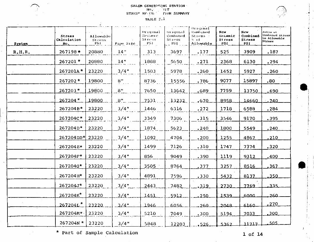
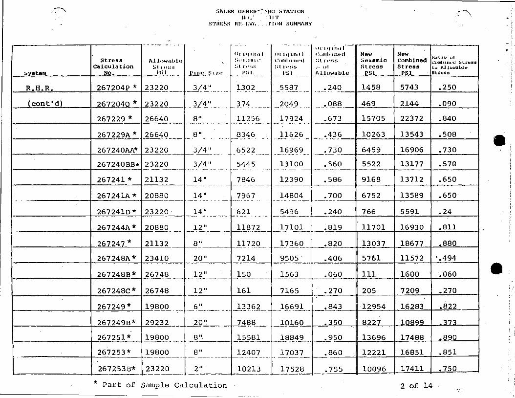
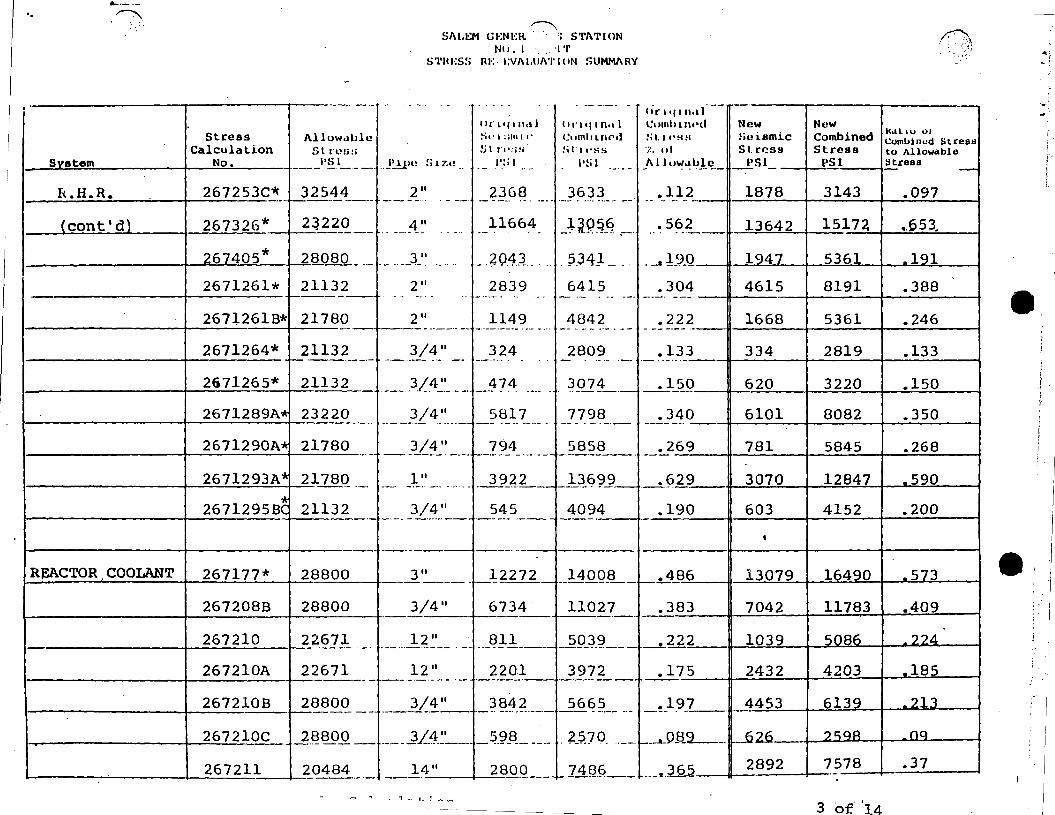
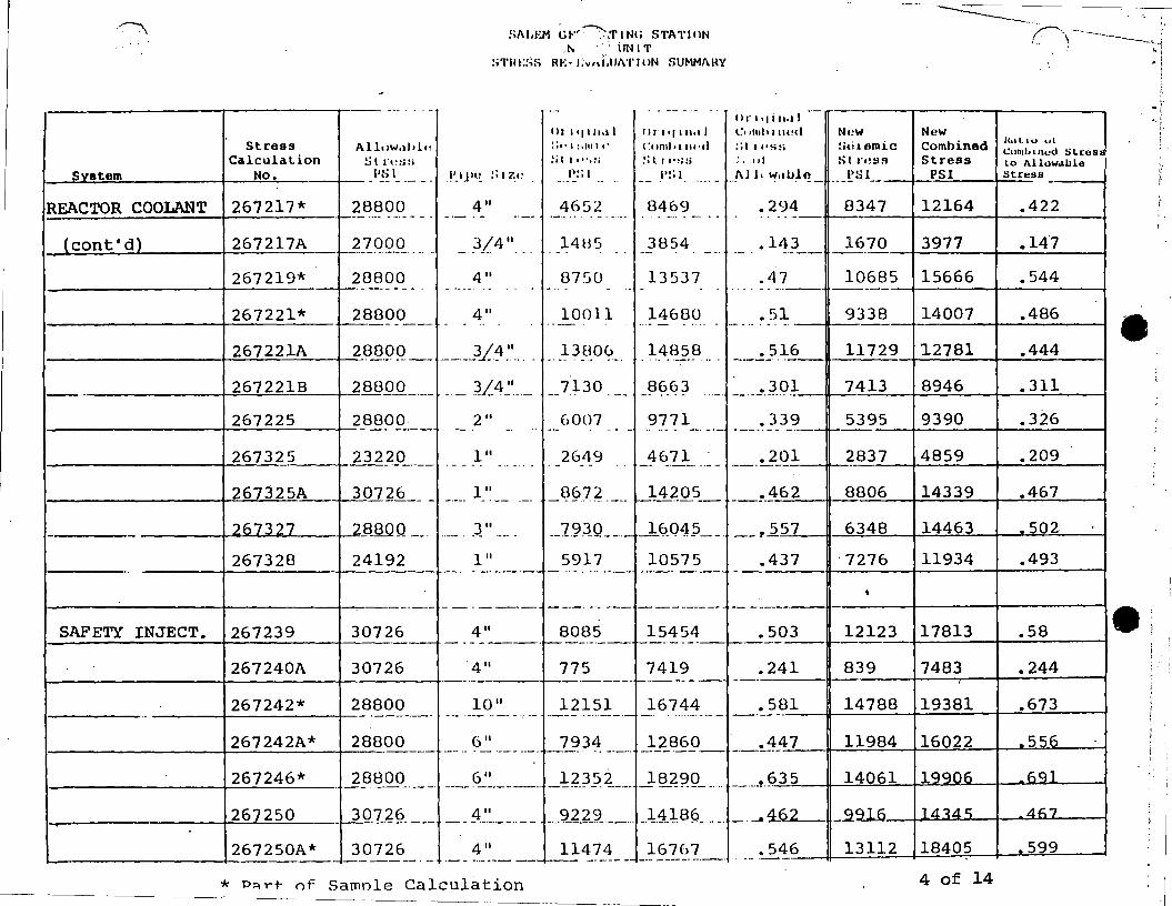
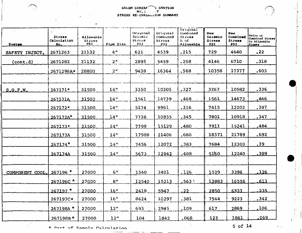
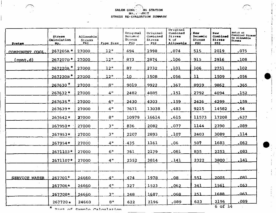
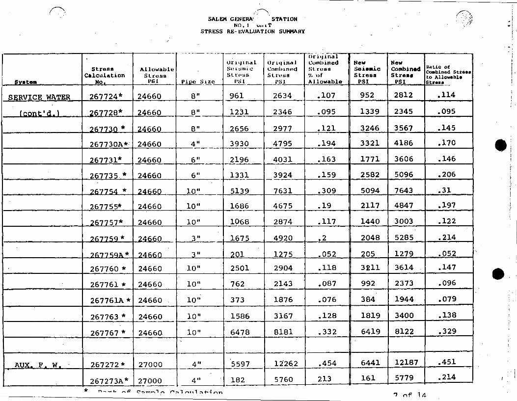
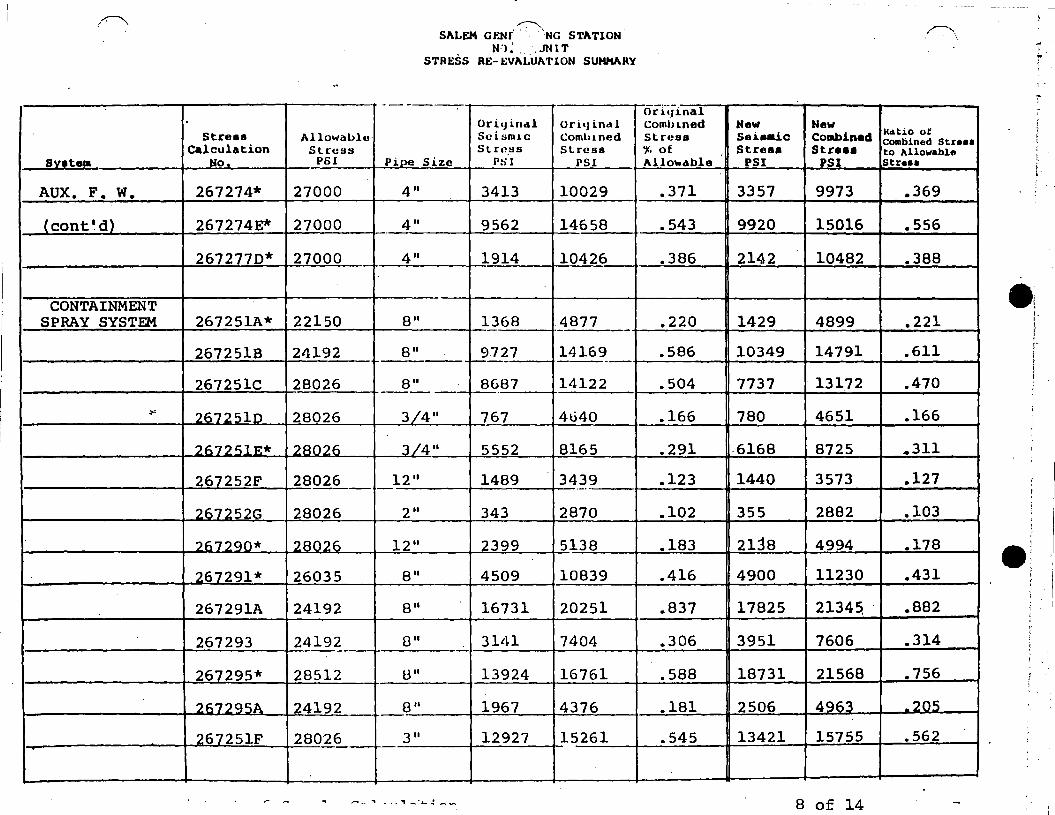
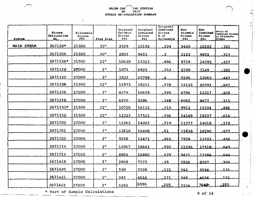
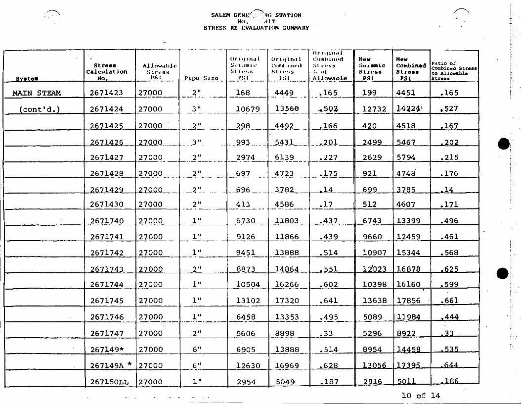
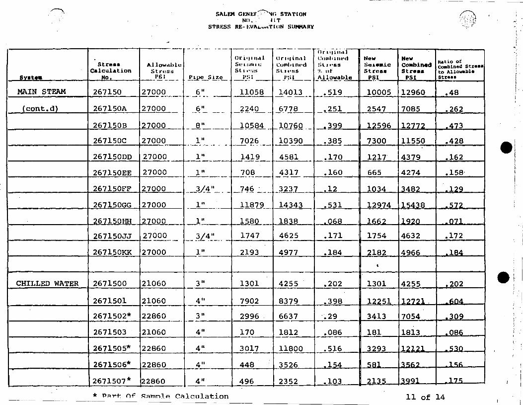
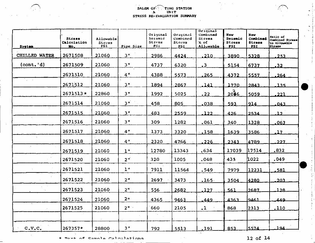
2. TABULATION OF STRESS RESULTS
2.1 Stress Re-evaluation Summary (See Talbe 2.1 Large and Small Bore Pipe)
These tabulations show the comparison between the
new reanalyses results {based on 3D SRSS-summation)
and the ori9inal analyses to determine the
percentage of variation. The allowable stresses
are based on DBE of B31Ql Code.
Conclusion:
The result of re-analyses indicate that none of
the pipe stresses exceed the allowables based on
the new criteria required by the I&E Bulletin 79•07.
2.2 Summary of Original Maximum Stress -Large Bore Pipe ( Se e T Ab le 2 • 2 )
We have tabulated the results based on DBE for
Large and Small Bore Pipe. Also, the original
stress and the percentage are identified, it con~
tributes towards total seismic stresses.
Conclusion: The seismic stresses do not exceed
60% of the allowables. We have included in our
tabulation pipe sizes as required.
P79 71 47 5
,...-· i
i. \. __
3. RESULTS OF PIPE SUPPORT RE-EVALUATION
We have re-evaluated 743 sample piping supports of
the 15 systems involving 138 piping calculations.
The percentage acceptable supports using new load
values based on reanalyses is 87%. Of the 96
supports that exceed the design margins 7.5%
Short term fix and shall be modified in the field.
3.1 Tabulation of Results
a) Total support re-evaluated 743
b) Total supports acceptable (new loads) 647
c) Percentage acceptable 87
Supports requiring Short Term Fix 56
Supports requiring Long Term Fix 40
Percentage requiring Short Term Fix
3.2 Pipe Support Structure, Weld & Bolt Sizing Criteria
7.5
Design of pipe supports for Salem is in accor-
dance with ANSI B31.1. Allowable stresses for
pipe support material are taken from this code
for all normal operation. Components used in
pipe supports, (rods, u-bolts, clamps and bolts)
are designed in accordance with ANSI B31.l and
MSSP 58. Bolting of structural components
associated with pipe supports are designed in
accordance with AISC.
P79 71 48 6
- ·- -· ···-•'··- .--- ·- ---·-·-··-- -· " ....
l '
3. RESULTS OF PIPE SUPPORT RE-EVALUATIONS
3.2 Pipe Support Structure, Weld & Bolt Sizing Criteria (Continued)
Allowable stress is increased to a maximum
value of 1.75 Sh for the maximum combined
loadings this includes Design Basis Earth-
quake.
Welded connections are designed in accordance
with 831.1. The maximum loading conditions
do not allow stress levels to exceed 24.0 KSI
for fillet welds.
Results of piping stress reanalyses are used
in the flexibility analyses and field
( evaluations, part of I&E Bulletin 79-02. '· .
Where flexibility analyses were performed prior
to receiving the values resulting from calcula-
tions for Bulletin 79-07 a reanalysis shall be
performed with the new values where these may
have exceed the original values.
( \
P79 71 49 7
1 ' J f
0··.
( 3. RESULTS OF ALL PIPE SUPPORT RE-EVALUATIONS
.·.:
3.3 Procedure for Evaluating Pipe Supports
The procedure for evaluati~g pipe supports is
included in this presentation.
3 • 4 In t er face w i th I E Bu 11 et i n 7 9-,0 2
Our response to this Bulletin was submitted to
your Staff on July 6, 1979, where we have
stated that base plate flexibility analysis is
in progress.
P79 71 50 8
-· ~- -1 •
r:.~' . \ ..
r·· ,_
I <
4. NOZZLE AND PENETRATION LOADINGS
4.1 Summary of Results
We have examined nozzle loadings on two (2)
Auxiliary Feedwater Pumps and one (1) Contain-
ment Spray Pump. The new forces and moments
obtained from our reanalyses were included in
our re-evaluation. Final results indicate no
overstressed conditions. We are continuing
this effort ~n the nozzles and penetrations
that is included in the reanalysis.
4.2 Criteria for Acceptability
Our criteria for acceptability were to examine
the allowables loads given to us.from the
equipment manufactuers. These allowables were
checked against the new loads we calculated.
If the forces/moments were within the
manufacturers allowables the equipment nozzle
was determined acceptable and no further
re-evaluation was required. We have informed
all the manufacturers that this process of
re-examining the nozzle reactions is in
progress. Should we come across an instance
where nozzle loads are increased over original
loads and exceed the manufacturers allowables
he will be informed and asked to verify the ac-
(: ceptability new loads
P79 71 50 9
.. I <
( ,.
c~_:_
s. PRIMARY COOLANT PRESSURE BOUNDARY PIPING
As stated in our initial response to I&E Bulletin
79-07, dated May 1, 1979, we informed the NRC that
the Reactor Coolant Loop Piping was analyzed by
Westinghouse for both DBE and OBE. In addition,
the piping within the Reactor Coolant pressure
boundary has been calculated by Westinghouse or
re-analyzed by us. Therefore, the concerns of
Bulletin 79-07 do not apply. See Westinghouse
letter dated April 23, 1979, attached.
P79 71 58 10
.. -· ·--·-··-- ··--··· - ... ·- - . -·····-·--___ ............. ,_ ........ .._ __ . __ , __ ~---··-- -' I i , I
p.: \ . '
(:
(_
6. FSAR PIPE BREAK REANALYSES EFFORT
Pipe break lines have been identified on piping
diagrams for their respective systems. We have
listed stress analysis calculation numbers ~nd
identified if postulated pipe break locations have
-changed. This effort is ongoing as the reanalysis is
progressing.
6.1 Results of Reanalyses
We have examined pipe break locations on Main
Steam Piping and it was concluded that
postulated pipe break locations did not change.
6.2 Pipe Break Location and Criteria
The criteria for analysis of high Energy piping
systems is addressed in Section 14.5.1.2 of the
Salem FSAR. This was based on the recommendation
of the reference 1 of Section 14.5 of the letter
from A. Giambusso (AEC) to F. W. Schneider
(PSE&G) dated December 18, 1972. It contained
the attachment "General information required for
consideration of the effects of a piping system
break outside containment."
P79 71 59 11
0--··
.· __ -._ ..
·- .. ---··
(.~. '-...'·.
---··--·-·-· --· ~- ·- - ·--~- ____ .. _,:. •• - ,_ --~ • - 0 ••••••
6.2 Pipe Break Location and Criteria (Continued)
This reference suggests criteria for location
of postulated pipe breaks.
1. At terminal points.
2. At locations where stresses due to normal
operational loadings associated with
seismic event are in excess of .8(Sb+Sa)
allowable stress.
3. At a minimum of two intermediate locations
between anchor points selected on a rea-
sonable basis as necessary to provide pro-
tection.
Based on the above we are reviewing the new stress
results. Additional pipe break protection
provisions may be found necessary if the
analysis per 79-07 indicates new stress levels
on any intermediate location exceeding the
.8(Sh+Sa) criteria. To date, our reanalysis
shows none of the calculations have exceeded
this limit.,.
12 P79 71 60
• l ' .
( '---
(
7. SEISMIC REANALYSIS METHODS
The method that was used to reanalyze the safety
related piping was response spectra model analysis.
It also incorporates summing up individual
responses by 3D SRSS load combinations. Valve
mass eccentricities are accounted for appropriate
stress intensification factors are considered.
7.1 Comparison Between Old/New Methods (Seismic Analysis)
We have informed you that the old method was to
add up algebraically X+Y ot Y+Z direction of
earthquake responses. This was our commitment
in the FSAR reference Q5.37.
Our new reanalysis methods employ 3D SRSS
combination for earthquake loadings
~x 2 + y 2 + z 2.
7.2 Seismic Anchor Movements
This has been addressed in our FSAR reference
Q5. 27-1.
13 P79 71 61
1--..
I '.
\ .. :·.
c:··:. '-.;.,. __ .·
8.
- ·-- ..... _. ____ ,:._. . ..__,~ -~ !.· .. .:-......_:.. .... -- '•. -··
NRC BULLETIN 79-02
As stated in our prelimina~y presentation to Staff
on June 19, 1979, our intent is to check results of
Bulletin I&E 79-07 if deemed necessary.
8.1 Implementation and Response
A copy of PS~&G letter to NRC dated July 6, 1979
is attached herewith, indicates method used to
implement requirements of I&E Bulletin 79-02.
14 P79 71 62
1-.
1' t ••
(' ·:· r.·(_;;~~ . \ I --·, °<
~ .: ... -
9.
- ··-··· . ·-·~-~~ ,·~. , ......... ·.- .. ,'., . - . -··
SAFETY RELATED PIPING NOT ANALYZED BY COMPUTERS
We have identified portions of safety related piping
which employed techniques using standard beam theory.
9.1 Techniques Used
Generally small bore piping at Salem Generating
Station is seismically analyzed using standard
verified computer programs as indicated in
Item No. 11. However there are cases where
small bore piping has been field run, and which
has been calculated seismically using guidelines
shown below.
9.1.l Seismic class I & II piping with operating
temperature of 1300 F and below and pipe size
1-1/2" or smaller was calculated for seismie
supports based on the following formula.
f = 92.87,~ Ref: "Formulas for V ~ Stress & Strain"
· WL4 by Roark
where f 30 cps to length.
is assumed to be determine span
15 P79 71 63
~-··· ..
r·
c·
___ :_ •-- ·------------- __ ,, -----·--·------- ~----. - ._.;:,, __ . __ .
- --- ---·-··-··-----" . - - -- .
10. VERIFICIATION OF "AS BUILT"
We have included in our submittal to you on
June 19, 1979 the procedure we used in identifying
as built" conditions. To add further assurance
and to comply with the requirements of this Bulletin,
we field walked the sample safety related piping
within the pressure boundary of the R. c. Loop and
found -it in compliance with our isometric sketches.
In addition, we agreed at our June 19 meeting to
perform a stress walk by ourselves and by the NRC~
That sample walk has taken place in the inaccessible
areas of the containment by the resident NRC
inspector together with our Stress Engineer. The
procedure that was followed was the same as pre-
viously submitted to you.
The results of these walks confirmed our previous
assertions that the actual configuration conforms
to the stress isometric drawings.
16
P79 71 64
Sl\l,fo:M G~:N~;P,.~,NG STATION· Nil. ·II T
STJn:s•: lff- 1:v. . l'ION SUMMAHY (~
' . .':,;·
'l'Al3LE 2 .1
----· ··- .. --·- .. I IJ I ·11~'1 c- - -
11r1q111.1l ll11q111.1l i:, 1111111111•<1 Nt!W New 1<.&l lu e..Jl
Stress Al low.1hl l•
Calculation St r·• ~:; ~' Svetem No. 1'6 I l ·- -- --- - . - . -
, I • 1 S!; !it!ismic Combined ComlJLllc(I :; L l u:;s
11 I Stress Stress LO Allowdbl~ Stru21a
. J_o~..i.1J_1-~- PSl PSI -St r •·~i!i
:;,.1·:.1111 c Cnml1u11·d !;1
'.%
I': i I l'Sl /\1
R.H.R. 267198. 2081:30 14" 313 3697 .177 525 3909 .187 ·---- - ···--·- - _ .. ..• - ·- -·
267201 * 20880 14 II 1888 5G 50 .271 2368 6130 .294 ------- ------
267201A * 23220 -·-·------- _ .. .260 1452 5927 .260 -·· _ 3(i'' ___ . .. ---~~-03 ___ - 5978
267202 * 19800 8" 8736 15556 .786 9077 15897 .80 -----·-·-- ·---- ·-267203* 198Q_Q ___ --· .689 7759 13750 .690 _!?_'..'_ __ - -- -- _ _7.f:>_?_Q _____ --~)_§:1~- --·-
267204 * .J.9.JiQQ __ ,_ - _U'.' ___________ 7_5Jl, ____ _ l.3.2J2. __ .• 0.]_Q_ 6956 14f.f.O _740
267204B* 23220 3/4" 1446 6316 .272 1718 6588 .284 --- --- ·---··--
267204C* 23220 3349 7306 .315 3546 9170 .395 - ... - ..___ ___ -- -- - -· ·- ---·--- --2672040* 23220 --- • 240 1800 5549 .240 . 1874 5b23 _3/_~_
26720400* 23220 ---- --·- -· .200 1255 4867 .210 - --- 3 /4. ~--- --- -19_9-_? __ -- --4 7 Q~ -· - -
267204E* 23220 3/4" 1499 7126 .310 1747 7374 .320 ,___ _____ , --
267204F* 23220 __l(i_" --l--8 5_6__ __9_q_49__ -- .390 11'1.9 9312 .400
267204G* 23220 - - .377 3257 8516 -367 _u~_:_ __ _ 3505 . 8764 ·-·------ ---- ··-·-
2672041-1* 23220 -- ---------· .330 5432 8137 _ 11)0 7596 3/4" 4891 -----·----"------ -------· . 267204J* 23220
·---------· .~lJ.~ ?710 77i:;q . ~ ~ i; _3L4_'~-- ~1_4}__ _ __ ]482 --- --
267204K* 23220 ~~-· ---+-~1~4 .5.1_ __ __ 53_u __ -- __._ 2.50 . 1 r::'lQ ~nnn ?CJ\
?f.7?Q.1L~_ _ 2.322.Q_ ____ _ _3/A'.~_:_- ._.J.9.4.6______ _6.0.56....___ _ _ ·-26.0 ., n11 o c.., c..n .270
267204M*· 23220 ·---- ------ - .300 5194 7033 .300
-··----_ 3(_~-·~- --- __ 5~1-~--- ,_J9_4_9_ -- --
267204N * 23220 --·----·-- - •. 5.26. 1;'1h? 11"71"7 - t:;(} i:; 3/4" 5848 ----+-·-----.. - - - 122_Q~_ ·-
* Part of Sample Calculation l of 14
~vatem -R.H.R.
(cont'd)
.....
-
Stress Cal cu la tion
No.
267204P *
2672040 * 267229 *
267229A * 267240AA*
267240BB* --267241 *
267241A *
2672410 *
267244A *
267247 *
267248A *
267248B*
267248C *
267249*
267249B*
267251*
267253* '
267253B*
5/\1,EM GJ-:N1·:w-:-·"'-tH: STATION r·i• •.' · ·'11 ·r
S'l'lh:ss RI-:-· LVI. ....... lllN SUMMARY
--- -·-- - .. - .
Al low.ah le !it a t~!iH
p:; I -- - . - ·-· -
23220 -----
2_3220 __
26640
c? S 17.e
__ ]/
."Ji 911
..
411 -·- ··--. --
411 - . -- ..
-- . - ----. -··
26640 ---- ----
23220 -----23220 --- -----21132
811 -- - - . - .. - -
411 -~L 3/
- --- .
411 - - ·-- -- -
14 II
.. . ..
Ila l'lllloll
~ ;, • a : an a '· !.i t •.•. : • ~ i
I':; I. ·- -- -- - . ·- ...
1302 - .. - .. -----·
.. ~-74 _ -----
11256 - -- - - . -- -· -
8346 ····- -- ..... ..
6522 - ···- - ·------
5445 -· ....... -·---
7846 - ---·· .. -- -· - - -·- --- --
20880 14 II 7967 ------ --- . - - ·- ---· - -- - ..
23220 14 II 621 ------ ----- ·--.,._ ____________
20880 12 II 11872 --·--- ---·- -- ---- --·-----
21132 11720 --~ ------- - ------- ~
23410 20 II 7214 ----- ·------26748 12 II 150 ---- --- ----·-----26748 12 II 161
19800 6' I 13362 . --- .. --· --- --- -·-------
29232 --II J4?Q ____ --·---
19800 8' I 15581 ----- ·-- - --------
19800 e· I 12407 ·--------- ----- ----- !--.·-· -··--- -----
23220 . 2' I 10213
·- - -·-·· ..
111aq1n.1 I l~omh 1111 •ll !lt t'•·:;s
I'S I ··-·-
5587 -· . ·-- ·-- ·- ---
-~Q_4_~ - ·--
17924 -- . - -·· - - -·
11626 -·---- ·-· .. . --
16969 ----·-·-- -·-
13100 -- --- -·- ··-
12390 --·-·--·-·-
14804 .. - - - ---···---
5496 ---------
17101 -··-· ---
17360 --------
9505 --·----1563
--·
7165
16691 -·--·-···----
10160 ------
18849 -- --------
17037 ------
17528 . - -- --------- ----1-----·--- -----·-
* Part of Sample Calculation
II I" I 'J l·tl,al -- ---1'.t11nl•1nt•d New !il. l'l'SS Se.1.emic ,<. "I St r(iss /\llowalJle PSI - ·---- --- --- -· -
.240 1458 ··-··-··· ---
.088 469 ·-·- - -----·-
.673 15705 --------
.436 10263 -- -- - --- -
.730 6459 ·a·---
.560 5522 -·------
.586 9168 ----
.700 6752 ------ ---
.240 766
~819 11701 ---
>--· .820 13037
.406 5761 ---
.060 111
.270 205
.843 ·12954 ---~350 8227
.950 13696 --- -
.860 12221 --·-
.755 10096 --··
New combined
llJL!O "I Comhuwtl :;jLl"t•SS
Stress Lu Al .lowall.lu PSI Struss
-
5743 .250
2144 .090
22372 .840
13543 .508
16906 .730
13177 .570
13712 .650
13589 .650
5591 .24
16930 .811
18677 .880
11572 '.494
1600 ·.060
7209 .270
16283 .822 -10899 .371
17488 .890
16851 .851
17411 .750
2 of 14
..
e. l
/ ,
I ' ! i i .,
I ' ! ·'
a...--·-
'•
..
Svstem
R.H.R.
Ccont'dl
REACTOR. COOLANT
--- -·-
Stress Alluw.iule Calculation Slt:l~:i:i
No. I'S l ---- ·-·-·--·
267253C~-- 32544 "--··-----
267326* 23220 ----
267405* 28080 - --
2671261* 21132 ~----
267l,.261B* 21780 -
2671264* 21132 '----·--·-
2671265* 21132
2671289A-A 23220 ----·--·
2671290A-A 21780 ·- -
2671293A'll 2178Q ·-
26712958~ 21132 --
267177* 28800
267208B 28800
267210 22671 - ·---·- ·-·
267210A 22671
.~.
S/\l.t.:M Gt:Nl·:rt . ': ST/\TlON Nll. I ·1 •r
s1·1n:ss Rt:. l;V/\l.ll/\'l' I ON SUMM/\RY
·- . - . -- ·-·-- -
lll"L•pn,11 II 1· 1q1 n.1 I S•·1 :;11111· C 11ml 1 l llC'd
!jl l'l':i~i· s I 11·ss
.. J~>l l'!i I --· --211 2368 3 633 ---- - ···- -··-·· --
. - --·-4" 11664 -~.9-~§ .-l
3_11 --- • - .. 20.4) __ ... !) --·-·-- . .'.34J_ ..
2" 2839 6 415 .. - ·-- . -· ---
2" 1149 4 842 - - ·- -·-. - -
3/4" 324 2 809 -··-··- ·- ·- ·-
074 ·--·- ··----·----3/4..:'._ -· -· __ -:17.4 ---- - . 3
3/4" 5817 7 798 ---·-.. -- ·- -----· -- -- -- --····- - - . -... _. __ -- 858 ----· 3 I:!_" ___ _7 ~-4- ___ _ _ 5
1 11 3922 1 3699 -- -· -··· -- ...... - ------ -·-··-·--
3/4" 545 4 094 ----- - -·----- ----- ---
----·
3 11 12272 --- - --------
3/4 11 6734.
12" 811 i.---···
12 II 2201
-·----
1
1
4QQ!L_
1027 --·-5039 --·---·----
3 972 --. ---·- -------267210B 28800 3842 5 665
. !.-----· -- ·- - -··-- -·-
267210C ~~800 __ ---- :_?_70. ·---.?L.4.~~---· --~-~-~--- ____ 2
267211 20484 ---·-·- -- 74~§ __ 14 11 2800 ---+--
. , -- ._.: ...........
I j r I • 11 llol l -----l:111t1l> 11\l'd New New !it.1 f'H~i !iui.emic Combined IC.tl IU UI
l:oml>inud Stres11 ·;~ .... St. ress Stress to Allowable _/\I Ju~~ l.JJ_ £.,! __ _ES! PSl Stress - -
.112 1878 3143 .097 -- ·- -- -· -···
.562 13642 1517~ •. 653. .. . ....
-_ _. J,_9_0 lq47 5361 _1q1
.304 4615 8191 .388 ---· ---·
.222 1668 5361 .246 e.
- -- ---- ·-
.133 334 2819 .133 ·-··-···
.150 620 3220 .150 -----
.340 6101 8082 .350 ------··
.269 781 5845 .268 ---
.629 3070 12847 -590 ·-·-·
.190 603 4152 .200 ----'
~-486 13079 16490 .5'73
.383 7042 11783 .409 ; .
_.222 1039 SOR,::. _??.ll
.175 2432 4203 .185 --_! __ 1_9_7 __ -· 4453 6139 .213
c..._..i..0.8-9__ __ -626 ?C\QA nQ
___ • __ l2.5_ 2892 7578 .37 ·-
Svatem
REACTOR COOLANT
(cont'd)
--··
-
..
SAFETY INJECT.
..
-
--- .. ··-
Stress All11w.,111., Calcula lion !3 t l't~!i~i
No. 1'8 l .. -·- - ---·-.
267217* 28800 ---·--- ----- - -
267217A 27000 ~--·--·-·--·--· - -· -·
267219* 28800 ·-·-----.
267221* 28800 -------·
267221A 28800 ···-·-----
267221B 2 88_90 -----
267225 28800 -- ----
267325 23220 -----
267325A __ _)_O 7 J-2_ __
267327 2EHiQQ ___
267328 24192
-----
267239 30726 ·--
267240A 30726
267242* 28800 ·-------
267242A* 28800 ·---·-
267246* 28800 . ---·---·--·
267250 -- 30_7_2-§ ___
267250A* 30726 ---·-~--·----. --
~i/\L,EM la·'~,TIN<i STA'l'IUN J.., ·. lJN IT
S'l'lll·:ss RE- L vni°.ll/\'I' I <>N .SU MM/\ HY
···-I i 11.J I
CJ1 I• p 11.ll or· 1 q 111.il c .. 111 Ii I I Wei
!;••1:.11111· Coml•11u·d :;111 •S!i
!il I 1 1 ',!'t !i l I I' .!'i ~; ·; , It I y_1111~ :; 17.1.• . f•:; I w.1Lile
411
__ 3/4 11
411
411
____ }l~ .··-·.
- - ~_L 4 ~·----2 II
111
111 -·--- - . ·--·· ---
-~II -- -
l"
411
. 411
10 11
4652
14B5
87'JO
10011
13BOG
7130
2649
__ Q97.~ ·---·
8469
3854
13537
14680
14858
8663
9771
4671 .
14205 --·----
__ :Z.9:1Q_ --- _1_9-04!) __ _
5917 10575
294 .. - ·-
143 -----'17 ·-·--·
51 - ....
516 -·-·.
301 ·-·······
339 - - ------
201
462
--~ 557
. 437 -- ··- -···· ·---· -····-- -·--- --
----
8085 15454 . 503 ---·-·--· --··- --··- - -----
775 7419 241
12151 16744 . 581 -·- ·--- ··---·.· ·-· ··---·--···-·--· --- . ······-·---- -·---·
6" 7934 12860 . 447 -··· .. ----·· --------- -·--
____ 6_'.~---· __ J:~)~-~--- _l.8~9-9_ -·· -·---·' J>35
--~-·~---·-- ___ 9-.22_9 ____ . _.+..1189 _______ _. 4.-6.2_
411 11474 16767 . 546 -·- ------ ·-·-· . -·- ·-
* Prlrr of Sample Calculation
Nt!W !.i•!J.emic 81 l"l!lHI
P!il --8347
1670 --·-
10685 ---9338
11729
7413
5395 -·--2837
8806
6348
•7276
t
12123
839
14788
11984
14061
_.9.9li
13112
~- "
New Combined Stress
PSI
12164
3977
15666
14007
'12781
8946
9390
4859
14339
14463
11934
17813
7483
19381
16022
l9qOfi
l LI ~.d. 'l
18405
4 of 14
P'~ ··-·----------... __ : i.( .
J(.,al lu ul
<.:umb111cd tilrt:s~
Lo Alluw.il.Jle Str~1111 -
.422
.14·7
.544
.486
.444
.311
.326
.209
.467
.502
.493
.58
.244
.673
.556
.h<°ll
Ll.t=.. 7
.599
:
;'
• i
' I·
' ;
~-. , . \
' '
- -
-~ SALEH Gt:NERJI ,.--...,i STATION ' ~) Nil. I T
. . ·~·
' . I
STRESS RE- t;VALI.> •• a ION SUMMARY ..
. -------- -·--- ... -- - ·---- -(ir-i;Tina-1
or 1•Jinal ori.lJindl Combined New New Stre11e Allowdl>le Sui:.;mic Comll1ned ~lrl!BS Se.Lamie Combined Natio ut
Combined Stre•• Calculation Struss SL ra?_~iS Struss % of Stress St re•• to Allowable
Sv•tem Ho. P61 Pine Size l'!i l _rs1 Allowable PSI PSI Str••• . -----·-·--
SAFETY INJECT. 2671263 21132 411 621 4539 .215 729 4640 .22 -
(cont.d) 2671282 21132 2" 2895 5459 .258 4146 6710 .318 -- ---------- -- -2671296A* 28800 211 9438 16364 .568 10358 17377 .603
·--------
---- ------· -
S.G.F.W. 267171* 31500 14 11 3350 10305 .327 3267 10582 .336 ---· --··--·--- ~
e r f
267171A 31500 - 14~--- _!_?_~ :!: ___ _ l.4_73~-- _!....468 1561 14673 .466
267172* 31500 14 11 5174 9961 .316 7415 12202 .387 ---->-----
?67172A* 31500 14~·---- _.]738 10855 .345 7801 10918 .347
' ?h7l 73* 31500 14 11 77_99 15129 .480 7911 15241 .484 I
267173A 31500 14 11 17988 21406 .680 18371 21789 .692 - i-------
267174* 31500 14" 7456_ 12072 .383 7684 12300 .39
2671711.'A. 3lSOO 14 11 5673 12842 .408 51'60 12240 .389
COMPONENT COOL. 267196 * 27000 611 1540 3401 .126 1529 3396 .126 •'
267l96C * 27000 911 12540 15213 -563 1. 13883 l6'li:\h .613 1:
?h7197 * 27000 16 11 _li_l_8 ___ l:)QL17 .22 281C)0 F".~33 ?~I:\
267197C* 27000 16 11 8424 10297 .381 7544 9223 .342 --- ·----- ---------r----
267198A * 27000 12" 693 29.45 .109 617 2869 .106 ,___ ____ >--·---- -· ----· ----- ,___
267198B * 27000 12 11 104 1842 .068 123 1861 .069
5 of 14
Stre•• Allowable C.lculation Slross
Sv•t•• No. P61
f"nM-u. •N .. -ru:T ,..nnT _ 267205A * 27000
Ccont.dl 2672070 * 27000
267220A * 27000
267220B * 27000
7fl7fl10 * 27onn ·
267632 * 27000
7fl7fl11:\ * ?70(}(}
267639* 27000 . 267642 * 27000
267950* 27000
267953 * 27000
267954* 27000
2671103* 27000
2671107* 27000
~F.RVTCF. WATER 267701* 24660
267706* 24660
267708* 24660
267720 * 24660
,,..--.,
SALF.M a•:Nl-~· ·.:.:\NG STATiON NO • j ' '·· lJN l T
STRESS RE- l~VALUATION SUMMARY
-···---·· -- -
Or i•1 tnal Ori•1indl Sc1:;m1c Cnml.J1ned St rc?:is Slrt!SS
Pi.oe Size p:;J ..._ PSI ·--12 II 494 1998
12 11 873 2874
12 11 87 2732
12 11 10 1508
A II QOlQ 9Q?2
411 2482 ~O~L ·-~---·-
--~·- _2~30 41n-:t
411 7671 13038 - -911 10979 16614
3 II 836 2082 -3 II 2207 2893
411 .435 1161
611 761 2179
411 2352 3814
411 .d.7A. lQ7B
411 327 1523
3 II 248 )..-2.H.1
8" 622 2196
. I
or-i"gTnal Cumliined New New K4t.i.o ot
Stress Sei .. ic combined Combined Str•••
'JC, ut Stre11• Streaa to Allo-bl• Str•••
Allowable PSI PSI ·-
.074 515 2019 .075
.106 915 2916 .108
.101 106 2751 .102
.056 11 1509 .056 .
.367 8959 QA62 .365
.151 2792 4094 .152
.1S9 2426 .d.?QQ _} 1:\9
.483 9215 14582 .54
.615 11573 17208 .637
.077 1144 2390 .089
.107 2403 3089 .114
.06 507 1683 .062 -
.081 835 2253 .083
.141 2322 3800' .141 '
OB 551 ?nni; nR1
.062 341 lsi:;.1 _063
_QnR 2.Sl 1flRR n,;~
.089 623 2196 .089 6 of 14
!.~ .... SALEH .Gt:NERA' · STATION
NO. I -.,., , T STRESS RE- 1-:VALUAT lllN SUMMARY
. -· ----- -· -· -- ---- ---· -----------. ·--·-oriqinal or llJ 1 nal OrL•J i.ncll Cumhi.ned
Stree11 Allowable S1!LW11ic l:omln n1!d St rt!SS CAlculation Slress 5L 1:1•ss Slrt!SS % of
svatem No- P61 PiE!C ~iZ'?___ I'S l 1'51 !.-------- '-Allowable
SERVICE WATER 267724* 24660 8" 961 2634 .107
(cont'd_\ 267728* 24660 8 II 1231 2346 .095
267710 * ?4f,f,Q 8" _ _6_656 2977 .121
267730A*: 24660 4" 3930 4795 .194 ---~---
267731* 24660 6" 2196 4031 .163 -
267735 * 24660 6" 1331 3924 .159 .._,_ ___ ?677'14 * ?Ll.~6n 10 11 513~ 7631 .309
267755* 24660 10 11 1686 4675 .19 --267757* 24660 10 11 1068 2874 .117
?f;77i;q * ?Ll.f;f;() 3 II 1675 4920 .2 ·-----?~77 r:;ar. * ?4i::.i::.o 3 II 201 1275 .052
267760 * 24660 10 11 2501 2904 .118
267761 * 24660 10 11 762 2143 .087
267761A * 24660 10 11 373 1876 .076
267763 * 24660 10 11 1586 3167 .128 ,__
267767 * 24660 10 11 6478 8181 .332
AUX. F- w_ 267272 * 27000 4" 5597 12'26.2 .454 ~--·-
-
267273A * 27000 4" 182 5760 213 -------
*
New Sei••ic Strea11
PSI
952
1339
3246
3321
1771
2582
5094
2117
1440
2048
205
3211
992
384
1819
6419 ,
6441
161
. /'f' ..
New Combined HaLio of
Streaa Combined Stte•• to Allo~bl8
PSI Str••• ·-·-
2812 .114
2345 .095
3567 .145
4186 .170
3606 .146
5096 .206
7643 .31
4847 .197
3003 .122
5285 .214
1279 .052
3614 .147
2373 .096
1944 .079
3400 .138
8122 .329
12187 .451
5779 .214
7 nf 14
i '
i· r
.I
.~, . SALEM GF'.Nf . . NG STATION
N1~ .. JNlT STRESS RE- EVALUATION SUMMARY
~ . I i·
, .. ----- Or [;jinal
Or i•J indl Ori•JLOdl Coml>Lned New New Rdtio ot Stre•a Allowal..llu Seismic Coml..11ned Stress Seiaaic Colllbined Combined Str•••
C.lculation Struss SL Ct~.ss Stress % of '
Streaa Str••• to Allowable Sv•teia Ho. PSI PinA Size P:ll PSI AU011oable PSI PSI Streaa
AUX. F. w. 267274* 27000 411 3413 10029 .371 3357 9973 .369
(cont'd) 267274E* 27000 4" 9562 14658 .543 9920 15016 .556
2672770* 27000 411 1914 10426 .386 2142 10482 .388
CONTAINMENT SPRAY SYSTF.M 267251A* 22150 8 II 1368 .4877 .220 1429 4899 .221 -
267251B 24192 911 9727 14169 .586 10349 14791 .611 ._ --267251C 28026 8 II 8687 14122 .504 7737 13172 .470 ------
,:.; 1672'lln 28026 3/4 11 767 4G40 .166 780 4651 .166
?.;7?i:;l R1r 7R026 3/4" 5552 8165 .291 -6168 8725 .311
267252F 28026 12 11 1489 3439 .123 1440 3573 .127 -- ·-
167252G 28026 2 II 343 2870 .102 355 2882 .103
?i;72qO* 28026 12 II 2399 5138 .183 21:~8 4994 .178
267291* 26035 911 4509 10839 .416 4900 11230 .431
267291A 24192 911 16731 20251 .837 17825 21345. .882
267293 24192 0 II 3141 7404 .306 3951 7606 .314
267295* 28512 U" 13924 16761 .588 18731 21568 .756
?67291:\A 24192 a 11 1967 4376 .181 2506 4963 _20s
267251F 28026 3 II 12927 15261 .545 13421 15755 .562
-~-., - .. ., -.·.a...: -- 8 of 14
SALEH GEN1~ING STATION NO UNIT
STRESS RE-J::VALUATION SUMMARY
orTginal Origi.nal original Combined New New
Ratio of Stre•• Allowable Seismic Coml.Jined Stress Sei••ic Combined Combined Str••• Calculation Stress Stress Stress % of Stress Strea• to Allowable
Svatea No. PSI Pi.,.. Size PSI PSI Allowable !?SI PSI su, ..
MAIN STEAM 267130* 31500 30 11 3539 10192 .324 344q 10102 .321
267130A 31500 30 11 2803 9453 _3 3323 qg72 3]7 1·
267132A* 31500 32 11 10639 15313 .486 9718 14392 .457
267132B 2'7000 3 II 1875 6825 .253 2199 7149 .. 26c;
267132C 27000 3 II 7933 10799 _4 GlQh 17nt:.? AA7
267132M 31500 32 II 12973 18211 .578 15155 20393 .647
267133A 27000 311 4579 10659 _395 4796 l1nl7 _AnR
267133B 27000 3 II 6970 Q1~h 14R h0f..:'I R477 11 C\
267133C* 31500 32 11 10720 16112 .515 9912 15304 .486
2671330 31500 3 2 11 12323 17511 -556 14149 19337 .614
2671700 . 27000 l" 12362 14003 .519 12377 14018 .519
2671701 27000 l" 13616 16468 .61 15438 1R790 .. 677
2671703 27000 2 II 9338 12473 _467 7q3R 1 ?-:t?? AC\t; e
'.
~
2671710 27000 211 12067 18643 ,.,
-6QO 112Qt; 17Ci1R t;.4Q
2671713 27000 2 II sqns lt:.OAn _f\?Q QA,?l , "7~0)1 t:.AA
2671419 27000 3 II 2869 7573 .28 3926 R107 10R
2671420 27000 2 II 558 3528 .131 i;.42 35?.4 111
2671421 27000 2 II 245 4616 . 1 71 1.l!.R A&;. 'H; , "7 'l
2671422 27000 3 II 3293 6996 • 259 ·- 11?.4 'Ja-Mh .. ·283 ··-
* Part of Sample Calculations 9 of 14
Stre•• Calculation
Svete• No.
MAIN STEAM 2671423
(cont 1 d.) 2671424
2671425
2671426
2671427
2671428
2671429
2671430
2671740
2671741
2671742
2671743
2671744
2671745
2671746
2671747
267l49*
267149A * 267150LL
-- -
Al low.ihl l~ St1·1!US
1'61 - -- ----
27000 --- .
27000 - .
27000
27_00_Q ____
27000 ----
27000 __ --
27000
27000
27000 --
27000
SALEH Gt:Na::(~~ .... c; STATION Nil. . .~I •r
STRt:ss RE- l·:VALUATJON SUMMARY
. - - -·-· .. - ·- - -- ···--- ----- - -Or1q1n.sl or i 'Ii n.1 I SPl!iOll 1: L'on1l 11 n1•cl S l I I'~,:~ ~l 11•!;s
y !.P~ __ s i. 7:~ _ I':; I -· _)•_:q _____ ----- -----211 168 4449 ·-·. --· --- ----- . --- .. --- --311 10679 13566 -- - ··- ----·· ---------·- --- ----
---~_'._'__ 298 __ 4:4~7 __ ---· "-··- ----- -
.. ---311 -- - -~-9J ---- .. _ __?4~_}.. ___
2" 2974 6139 ·---- ---- .. -- -- -----·-- ·---- -----2 II -~~7 4723 -·-·--- ··- . --- - - .. -- .. -- . -
-~·~- --- - - .. -99..6 -·- .. .. 3.7~_2.._ __
2 II 413 4586 -----·-·-- -- ----- -- ·- --- ------1 II 6730 11803 ---- -- ---~-· >-·---
111 9126 11866 --- --- ----- - ---·--------···-·-·-
27000 1 II 9451 13888 ·-- --·--·- ------·- ---·
27000 2 II 8873 14864 - -- --
27000 111 10504 16266 ----·---· -----
27000 111 13102 17320
27000 l" 6458 13353 ---·---···------- --- ·-27000 2 II 5606 8898 ------ t--------- ·--27000 611 6905 13888 -- ---------27000 611 12630 16969 - --- ---------27000 l" 2954 5049
-,;r • •i (1i.i_l_ C11111h 1111•ct New :ii 1"•~59 !>tu•111ic ... of st Cl!811
_J\_!_l_~~~-"-!L PSI -·-'
.165 199 ·- - -- ---
.... 504 12732 ----~166 420
- -~-;2.Ql- 2499
."227 2629 ----
.175 921 --· ----
.14 __ ---2.29.
.17 512 -
.437 6743 --
.439 9660
.514 10907 -
.551 12'023
.602 10398
.641 13638
.495 5089 ---
.33 5296
.. ~_1_4 8954
.628 13056
.187 2916
·-Hew Combined KatJ.o ot
Combined Str••• St re•• to Allowable
PSI Str•••
4451 .165
l4~~4r-' ,S27
4518 .167
5467 .202
5794 .215
4748 .176
3785 -14
4607 .171
13399 .496
12459 .461
15344 .568
16878 .625
16160 .599 . 17856 .661
11984 .444
8922 • 3.1
14458 - !:i.1 i:;
173Q'i - h.d..d.
5011 .l81i.
10 of 14
i I
+ f ' I f
" t f
t [ " l ' 1· I ;
" '· ,,. ~
'I i I
SALEM Gt:Nt.:r~c; STATION tm.. llT .
STRt-:ss RE- l·:VAl.·u••'r ltlN SUMMARY
-- ... ·-- ·- -- ------ ----- l1r' 1 •.ii"1i.1.i Or i'I 111cil Ori'! inc\ I t:11ml 11111•d
Stre•• Allowc1hll! SI' I :;m I 1; l'.11ml11 n1•d :;l11'69
Calculation Stn:ss Sl I '''ili !il.1·t 1 !1S '.%. 11t' s •t • Ho P61 _r_~_s i_z.~ . I':; I I':; 1 _A_!_l_Q~~ble ·--·· -- r-------· ·--
MAIN STEAM 267150 27000 6" 11058 14013 .519 ------- -·---- -- -- ---·-
cont.d 267150A 27000
267150B 27000
267150C 27000
26715000 27000
267150EE 27000
267150FF 27000
267150GG 27000
•~~~~~~~~---........... i...=..~H!L 2 000
267150JJ 27000
CHILLED WATER
267150KK 27000
2671500 21060
2671501 21060
2671502* 22860
2671503 21060
2671505* 22860
2671506* 22860
2671507* 22860
6" -- - - -- ...
_..!!'_' ----
l" ----··---- - .
l" -------l" --------3_/4 11
·- -- ·-·. -
l" ---·--·--
l"
- _3_L 4~·--.
l" ---
3 II
4" --3 II
-411
411
411
411 ·--
* P~r~ n¥ R~mnlR Calculation
2240 _6_7]!!__ _!.251 --··· ·-·--
_ _! p_~.84 --~,1_0790 . - _.&399
7026 10390 .385 -·- -- ··--- ---
1419 4581 .170 ----- - -708 4317 .160 ----·---- ----
_.74§ _:_ __ - -~~3_7 ___ .12
_!1~79 ___ _!_43.il_ . .531
1580 1838 _068
1747 4625 .171 - -- .
2193 4977 .184
1301 4255 .202 -7902 8379 .398
2996 6637 .• 29 -
170 1812 .086 -----3017 11800 .516 ·- ----448 3526 -1'14
496 2352 .103
Hew New RAtio ot S111.•aic Coabined combined St1:••• Steese Stre•a to Allo-bl• P~I PSI Str•••
10005 12960 .48
2547 7085 .262
12596 12772 _473
7300 11550 .428
1211· 4379 .162
665 4274 .158·
1034 3482 -129
12974 l '14~R _i;72
lF..F..2 1920 .n71
1754 4632 .172
2182 4966 -lR4
'
1301 4255 .202 i :
12251 12721 . e.n4 ~ .
!
3413 7054 .309 ~ .
' 181 1813 .nR6
3293 12121 - s:;':ln
~Rl ~"f;? 1 l:.t:.
213" ~qql 17~
11 of 14
. . .---... SALEM Gf'.'. : . 'TING STATIQN ·.,C\
.. h UNlT STRESS RE-EVALUATION SUMMARY
·- -·-------...----- --0·,·1<Jin.i1 OricJinal Ori1J in.al combLned New New
Ratio of Stre•• AllowalJle Sc1sm1c Comhined Stress Sei.111aic Combined Combined Str•••
calculation Strc!IS Str1!sa Slrcss ·x. of St res• Streaa to Allowable S"•t• .. Nn_ 1:'61 Pi.oe Size PSI PSI Allvwable PSI PSI Streea
CHILLED WATER 2671508 21060 311 2986 4424 _210 3AQO c;12A - ']I:\ l
(cont.'d) 2671509 21060 3 II 4737 6320 .3 5154 6737 _32
2671510 21060 411 4388 5573 -265 4177 'i'il:\7 _?1;4
267f512 21060 3_·~---· 1894 .2867 _ 1LL1 177n ?RLL "::t 1 "::t c;
-.z. 2671513 * 22860 3 II 1992 5025 .22 2016 5059 _771
2671514 21060 3 II 458 ·-~---
805 -038 c;q1 Q1Ll. _nA"::t
2671515 21060 3 II 483 2559 - 17, 4 ?f. ., c; 14 1 .,
2671516 21060 3 II 309 1282 .061 340 1328 .063
2671517 21060 411 1373 3320 .• 158 1639 3586 _17
2671518 21060 4" 2320 4766 . - 226 7.141 .47RQ ,,., 2671519 21060 l" 12.780 13343 .634 17039 17514 .832
2671520 21060 2" 320 1005 .048 435 1022 .049
2671521 21060 l" 7911 11564 .549 7979 12231 -581
2671522 21060 2 II 2697 3473 .165· 3504 l42Bn . ?n-:t
. 2671523 21060 2" 556 2682 .127 c;r; 1 l?~R? 1 ?R
2671524 21060 211 4365 9463 _AAQ .d "::t~ "::t .nA~i A An
2671525 21060 2" '660 2105 .1 868 2313 .110
-· c.v.c. 267357* 28800 3 II 792 5513 .191 Rl:\1 c; c; "7 A 1 nA
12 of 14
1--.
. '
I' J•,
( . '-
,(
(
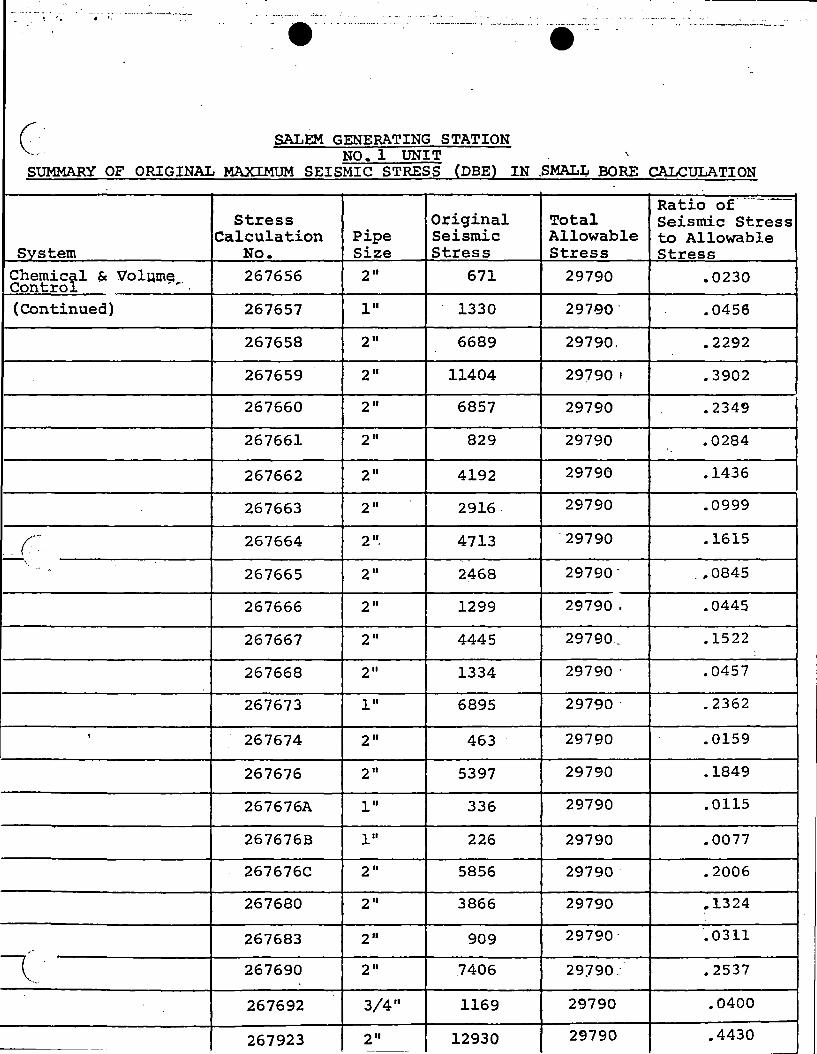
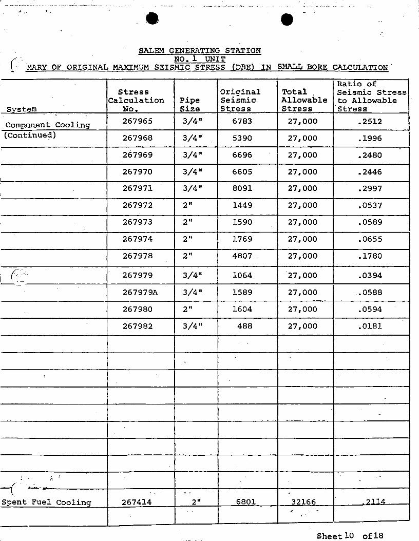
TABLE 2.2
Table 2.2 consists of the following:
1.
2.
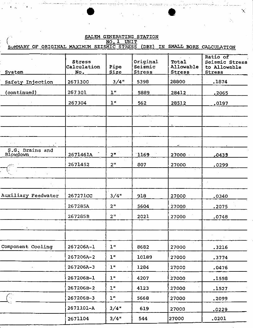
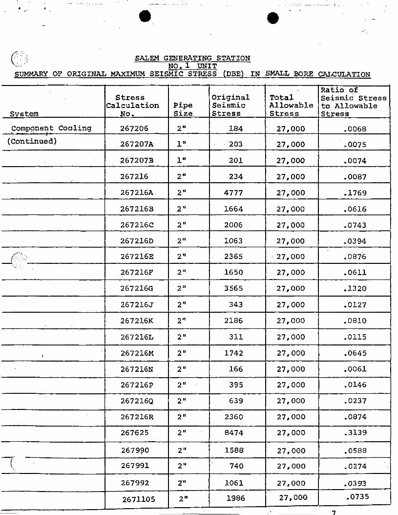
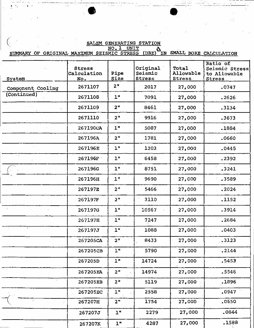
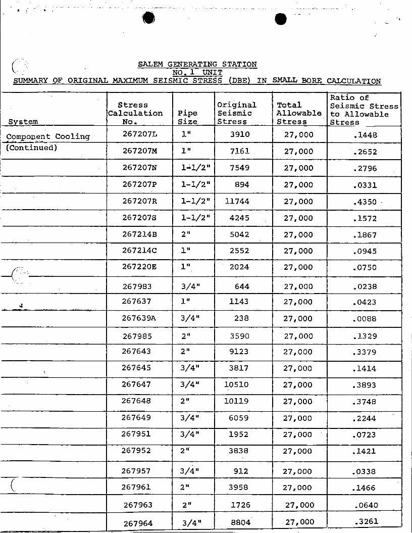
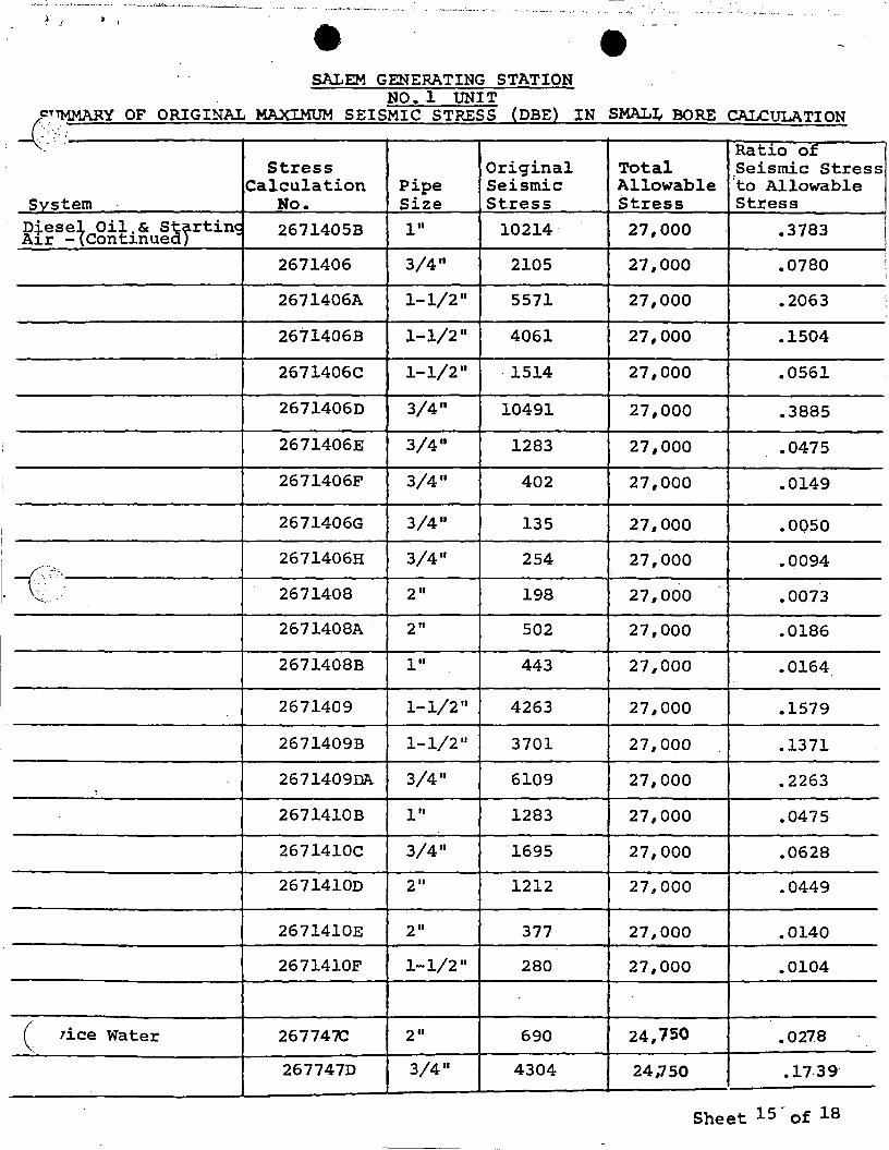
18 Sheets of Summary of Original Maximum Seismic Stress (DBE) in Small Bore Calculation
9 Sheets of Summary of Original Maximum Seismic Stress (DBE) in Large Bore Calculation
\ c_:
c
(
, -SALEM GF.Nt:R/ ~ STATION
/ . "\ ,c:-\ .·!
NO. I IT ... ·,·:
STRESS RE- l·:VALUATHlN SUMMARY
.. -- - -- --- -- ----- ··----- (fr11j"(r\.1"1 .
' Ori..,inc1l Ora'f ind l Cumhi.ned New New Stre•• Allowdhlc St? I :;m 1 i: Comlaanr.d !il rt~BB Se1.•111ic Colllbined Ratio of
Combined Str••• calculation Strt?SS SL l"l'n!I Slrt•ss % of St rel!lll Stre1111 to Allowable
8v•t- HO- 1'61 . .f.!E~_s !-~~ - I' ~i I Nil Allowable PSI PSI Stre•• - - ---· --·-·-- ~-----· >---·
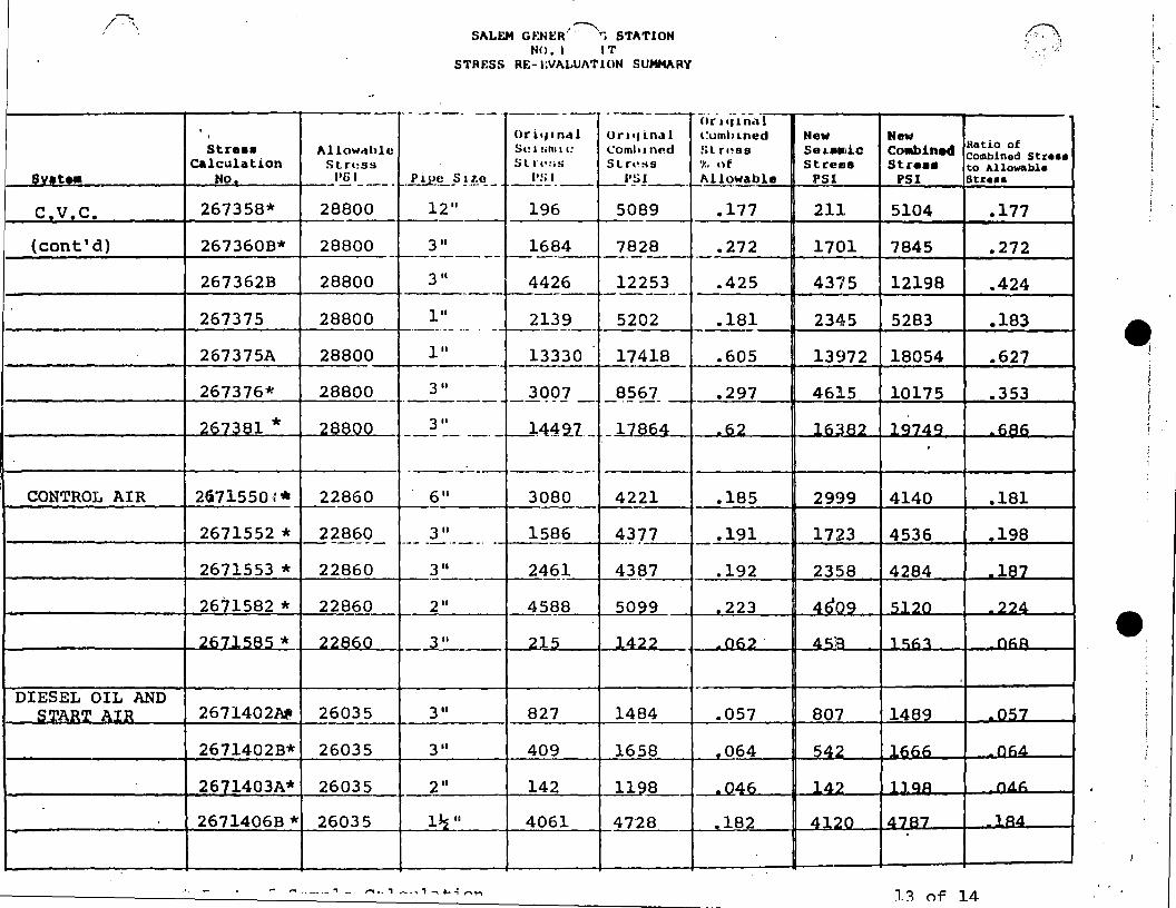
c.v.c. 267358* 28800 12 11 196 5089 .177 211 5104 .177 ·-{cont'd) 267360B* 28800 3 II 1684 7828 .272 1701 7845 .272
-~------ --· -·---
267362B 28800 3 II 4426 12253 .425 4375 12198 .424 ··--~------ ----··-
267375 28800 111 2139 5202 .181 2345 5283 .183 ·---·---. -- -·- - -- i-------
267375A 28800 111 13330 17418 .605 13972 18054 .627 • I
' 267376* 28800 3 II
_l_Q9] - _8_?67_ .297 4615 10175 .353 -·----! !
267381 * 28800 3" ..__l4:4~1- _]J.R64 .62 l63A2 ]q74q .6A6 --- --· --·-
·---- --· ·----· CONTROL AIR 2671550~* 22860
·-"----6 II 3080 4221 .185 2999 4140 .181
2671552 * 22860 3 II 1586 4377 .191 1723 4536 .198 ----- -- ------· - ---··----2671553 * 22860 3 II 2461 4387 .192 2358 4284 .187 ·----2671582 * 22860 2 II 45f?8 5099 -223 4~0Q c;1 ?n - 2?.d
7671 c;Rs * 22860 3 II 215 ld.?2 06?" d. c;):l , c;.f;. ~ n~s:i
DIESEL OIL AND S'T'AR'T' ATR 2671402,Nt 26035 3 II 827 1484 .057 807 1489 _ os;7
2671402B* 26035 3 II 409 1658 .064 s;A.? 1 f".nn _OkA
2671403A* 26035 2 II 142 1198 _._Q4f". , il ') , , QJ:l nA .i=_
·-2671406B * 26035 lJ.s II 4061 47"28 -182 4120 d.7A7 , Qil
,.. ,.... -. ·-~ ·- , ~ ,.... -- ., -... , -....... .; ,..... .,.... l~ of 14
,--.. SALEH Gf-:Nt:R/ · ·r, STATION
NO. I IT STJU;ss RE-1·:VALv1.i'ION SUMMARY
-----· ----
Stre•• Allow<1hlt! C.lculation Stru:rn
S •tea No P61 ·-~:.i..:==-------i-....:.:=-.s..---+--- - ---·- Y.!£~.s l!c~-
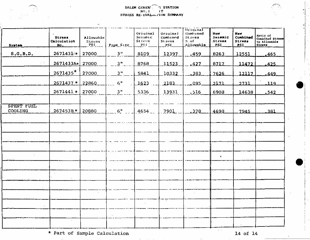
267143lr* 27000 311 S.G.B.D. , ____ .;.._ ____ -4~-----+----- - -------
2671433A* 27000 - _ 1" ·- --· -
2671435*. 27000_ -
26 143 * 22860 __ . -
2671441 * 27000
__ l_'_' ·- -·
--- q"
·----------li-------+----·-- - 3"
SPENT FUEL COOLING 267453B * 20880
11----------t-------t-------
·----------l------+-- ---- --
-------
----------
·--- 6~' -·· -
---- -- - . ··--·
-----·
·- ·-- -- -- -
----------+------ ------- -- - - ---------
·------
·----------+------.J------- ·-------
·----------4------+-------- -·----· ·-
----- ·-
·-·-----·--
·------·-
* Part of Sample Calculation
----- -----Or i•1 i nal Oriqi.ndJ Se a sm a 1: Coml11nf'd St r-l':;s Sl.n!ss
l'~i I _ _J•?t __ --- --8109 123TI_
8768 11523 ------ -----·-5841
~-·------,_ J..Q_J_:u__
__ .l.22.3 . - - _ _llB.L _
5336 13931 -------- -- .. - --------
----· - --- -···-- .. -
-4_~54 --·- _ _I~Q.L --·
- ----- --
-------· ---
--- --· ----
---·-· -- --·----
----- --·- --
,____ -------
---- ·-------
--·----· ·-·-
--·-------------
--·---
cir"i·l"1ii.11 Coml•aned New New
Ratio of :;l l"•!SS Se.a.8laiC Cotabin9d Combined Stre•• .. , uf Stress St re•• to Allowable I·•
Allowable P~I PSI Str••• ~----
.459 8263 12551 .465 . '
.427 871'7 11.d..72 _4, i; i
·-
-~83 7626 1?117 _44q
____ 095 ?171 ?7~1 1, Q
.~16 6908 14638 .542
--·
.378 46QR 7<:}4.r:; _ 1R1
-
·---
- ·-I
---· e:
---·
-·
14 of 14 ------------- ---------
--·- -- ·. - -- --~· --· ·--~--1(. •• It... - . -:.-~~-:-:---- -- --------- -··· __ ...... _ ..... -·::"-.:."'·--""':' :·.-.:.-··-·-·"'-···--~ .. --. ----·-,----· .......... _._, ___ .,~-~-'~ .... ·.······-- e ·-
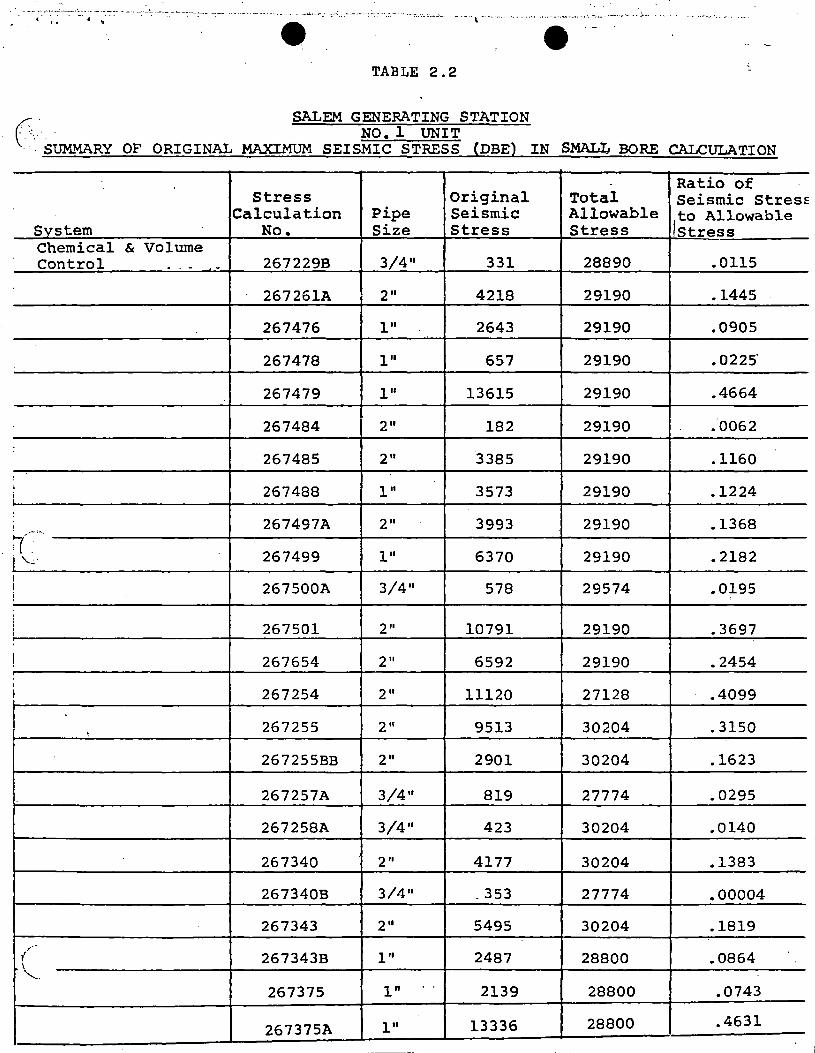
TABLE 2.2
SALEM GENERATING STATION
0.s~RY OF ORIGINAL MAXIMUM SEIS:~c ~T:~~ (DBE) IN SMALJ., BORE cALcULATION
- Ratio of Stress Original Total Seismic Stresf:
Calculation Pipe Seismic Allowable Ito Allowable System No. Size Stress Stress Stress Chemical & Volume Control - . - - 267229B 3/4 11 331 28890 .0115
267261A 2" 4218 29190 .1445
267476 1" 2643 29190 .0905
267478 1" 657 29190 • 0225·
267479 l" 13615 29190 .4664
267484 2" 182 29190 ."0062
267485 2" 3385 29190 .1160 !
I 267488 l" 3573 29190 .1224 i ~
I 267497A 2" 3993 29190 .1368 -·:..
~(. 267499 l" 6370 29190 .2182 i '-..:.:
! 3/4" I 267500A 578 29574 .0195
!
' j 267501 2" 10791 29190 .3697 :
! 267654 2" 6592 29190 .2454
' I 267254 2" 11120 27128 .4099
' 267255 2" 9513 30204 .3150
267255BB 2" 2901 30204 .1623
267257A 3/4" 819 27774 .0295
267258A 3/4" 423 30204 .0140
267340 2" 4177 30204 .1383
267340B 3/4 11 - 353 27774 .00004
267343 2" 5495 30204 .1819
(" 267343B l" 2487 28800 .0864 '-...
267375 1" ..
2139 28800 .0743
267375A 1" 13336 28800 .4631
-- --
_, .... -·-· . . -- - ···-· ··-··-"'" . ..._._:... ___ ._ - .. ., . .:. .... __ -·--·-· . - -·- .. ··-· -··- -- -- -' . • .. -- - ·- ... ____ .,.. -· . ... ·- -.. e· .. - -··-··-'•···· -······- .. .. ---..... ···-~---· --- ---~--- ... . .. ---~--- ---- . ., --·--------·---·-e - -
-
(_ SALEM GENERATING STATION NO. 1 UNIT '
SUMMARY OF ORIGINAL MAXIMUM SEISMIC STRESS (DBE} IN .SMALI,. BORE CALCULATION
Ratio of··--- -
Stress Original Total Seismic Stress Calculation Pipe Seismic Allowable to Allowable
svstem No. Size Stress Stress Stress Chemical Control
6c Volum~,. 267656 211 671 29790 .0230
(Continued) 267657 l" 1330 29790' .0458
267658 2" 6689 29790. .2292
267659 211 11404 29790' .3902
267660 2 II 6857 29790 .234g
267661 2 II 829 29790 .0284
267662 2 II 4192 29790 .1436
267663 2 II 2916- 29790 .0999
(--.- 267664 2 11_ 4713 ·29790 .1615 -,·
..•
267665 211 2468 29790- - ~ 0845
267666 2 II 1299 29790. .0445
267667 211 4445 29790_ .1522
267668 2" 1334 29790. .0457
267673 l" 6895 29790. .2362
' 267674 2 II 463 29790 .0159
267676 2 II 5397 29790 .1849
267676A 111 336 29790 .0115
267676B l" 226 29790 .0077
267676C 2" 5856 29790. .2006
267680 2" 3866 29790 .1324
267683 2 II 909 29790· .0311
~ 267690 2 II 7406 29790- .2537 ...
267692 3/4 11 1169 29790 .0400
267923 2" 12930 2g790 .4430 -- - - --
________ ..__. -· '-·· ··~- --- .. ---·-· ... ~-- - -·- ... -·- - '-·· ···. ·- . . . .
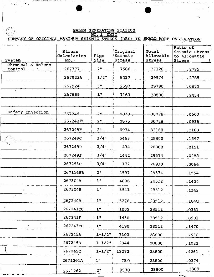
(:- ·-_ .. :. SALEM GENERATING STATION .:":~· NO. 1 UNIT SUMMARY OF ORIGINAL MAXIMUM SEISMIC STRESS (DBE) IN SMAL4 BORE CALCULATION
Ratio of :
' Stress Original Total Seismic Stress
. Calculation Pipe Seismic Allowable to Allowable
Svstem No.· Size Stress Stress Stress I
Chemical & Volume Control - 267377 2" 7586 27128 .. 2785
267922A 1/2" 8237 29574 .2785
267924 3" 2597 29790 .0872
267655 1" 7163 28800 .2454
267248 E 2 II 2875 30728 .0936
267248F 2" 6974 32168 .2168
2672490 3/4"
267249J 3/4" 1442 29574 ~0488
2672530 3/4" 172 26910 .0064
2671168B 2" 4597 29574 .1554
267304A 1" ·4006 28512 .1405
267304B l" 3541 28512 .1242
267241CC l" 1002 28512 .0351
267241F 1" 1430 28512 .0501
267243CC l" 4190 28512 .1470
267245A 1-1/2" 7303 28800 .2536
267245B 1-1/2" 2944 28800 .1022
f( I . .4261 267245C 1-1/2" 12272. 28800
2671261A 1" 7'8 9 28800 .0274
'~~~_:_~~~~~_J.:__~2~67~1~2~6~2:___J__.:2~·-·~--L~9~5~3~0:..._~~~2~8~8-0_0~-·-~-=--·-3_3_09~--,~
. . ----··-"~-----~-·-.. - - - -· - ~--"""--·.:~....;. "-----------------···--·- -~- -"------ --·---;.~_ .... ____ ~ ·----····--- ------ -------·--···---. ' --'-------'"- - -- . ------ .. - ·'
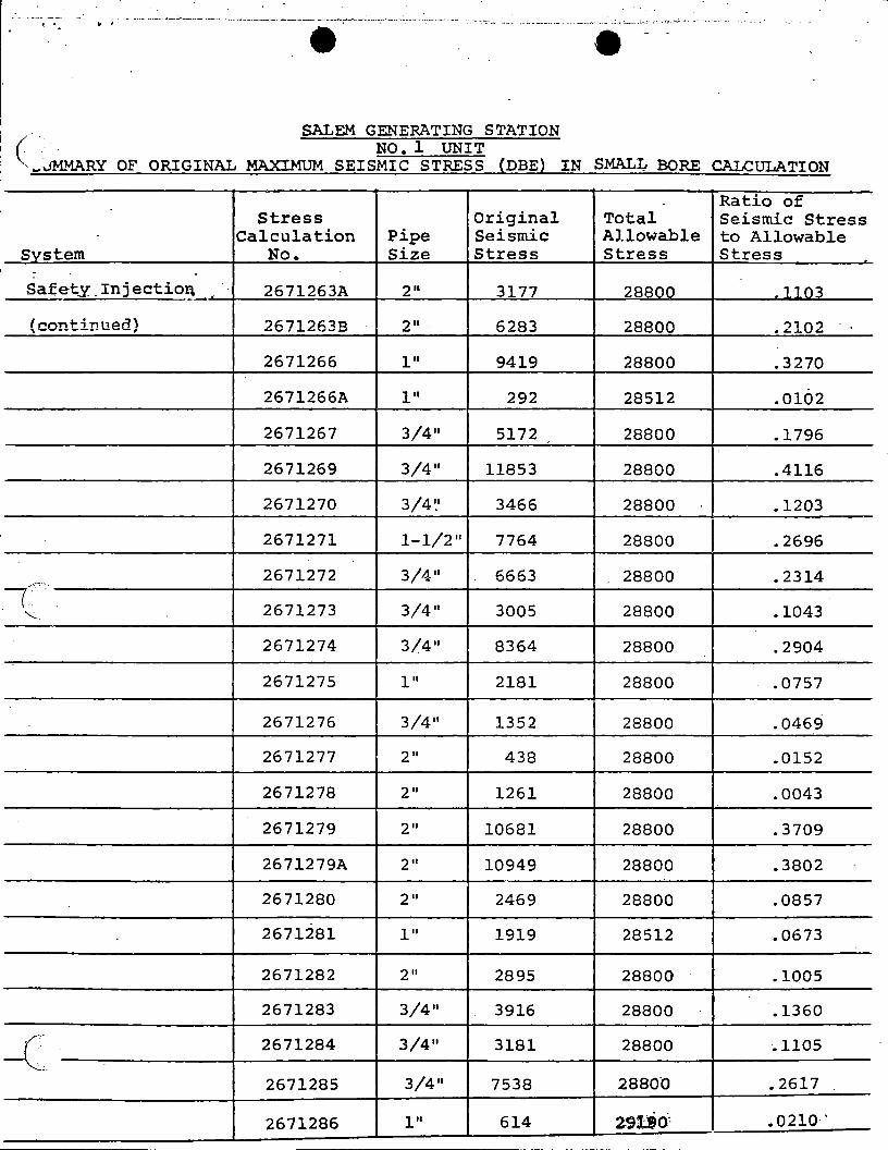
SALEM GENERATING STATION c· ·.. NO. 1 UNIT ~ ... jMMARY OF ORIGINAL MAXIMUM SEISMIC STRESS (DBE) IN SMALL BORE CALCULATION
Ratio of Stress Original Total Seismic Stress
Calculation Pipe Seismic Allowable to Allowable Svstem No. Size Stress Stress Stress
. -Safe~y_Injectio~- 2671263A 2" 3177 28800 _1103
(continued) 2671263B 2". 6283 28800 .2102
2671266 1" 9419 28800 .3270
2671266A 1" 292 28512 .0102
2671267 3/4 11 5172 28800 .1796
2671269 3/4" 11853 28800 .4116
2671270 3/4~' 3466 28800 .1203
2671271 1-1/2 11 7764 28800 .2696
2671272 3/4 11 ... -::-"":···.
6663 28800 .2314 -r 2671273 3/4" 3005 28800 .1043 "'-..
2671274 3/4" 8364 28800 .2904
2671275 1" 2181 28800 .0757
2671276 3/4" 1352 28800 .0469
2671277 2" 438 28800 .0152
2671278 2" 1261 28800 .0043
2671279 2" 10681 28800 .3709
2671279A 2" 10949 28800 .3802
2671280 2" 2469 28800 .0857
2671281 l" 1919 28512 .0673
2671282 2" 2895 28800 .1005
2671283 3/4" 3916 28800 .1360
c· . 2671284 3/4" 3181 28800 .1105
2671285 3/4" 7538 28800 .2617
2671286 1" 614 291..t<i· .0210·'
- ' ···~·~- - . - ··-- ... - ._. ___ ,_,_ _ __;,... -·-~· ... --~-----·--··----·--· -~-------··---. ------·----·-·--- -· ' ' .
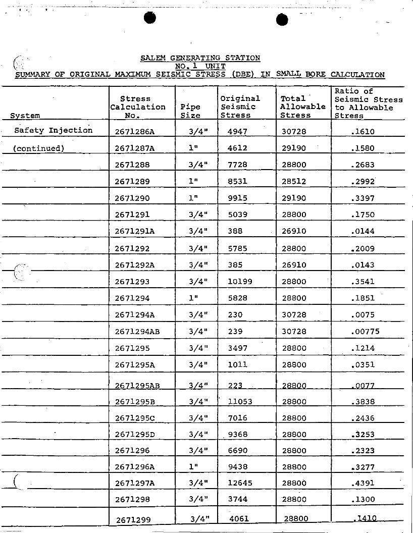
(/-_· , SALEM GENERATING STATION '·. NO. 1 UNIT SUMMARY OF ORIGINAL MAXIMUM SEISMIC STRESS (DBE) IN SMALL BORE CALCULATION
Ratio of -Stress Original Total Seismic Stress
Calculation Pipe Seismic Allowable to Allowable Svstem No. Size Stress Stress Stress
Safety Injection 2671286A 3/4 11 4947 30728 .1610
(continued} 2671287A l" 4612 29190 .1580
2671288 3/4" 7728 28800 .2683
2671289 l" 8531 28512 .2992
2671290 1" 9915 29190 .3397 '
2671291 3/4 11 5039 28800 .1750
2671291A 3/4 11 388 26910 .0144
2671292 3/4 11 5785 28800 .2009
-{', . 2671292A 3/4" 385 26910 .0143 .
' ·-··· 2671293 3/4 11 10199 28800 .3541
2671294 l" 5828 28800 .1851
2671294A 3/4 11 230 30728 .0075
2671294AB 3/4 11 239 30728 .00775
2671295 3/4 11 3497 28800 .1214
2671295A 3/4 11 1011 28800 .0351
2671295AB 3/4 11 223 28800 _0077
2671295B 3/4 11 11053 28800 .3838
2671295C 3/4 11 7016 28800 .2436
26712950 3/4 11 9368 28800 .3253
2671296 3/4 11 6690 28800 .2323
2671296A l" 9438 28800 .. 3277
_( 2671297A 3/4 11 12645 28800 .4391 '·-
2671298 3/4 11 3744 -20000 .1300
2671299 3/4" 4061 28800 .1!1:1Q
• •
( SALEM GENERATING STATION
NO. 1 UNIT SUMMARY OF ORIGINAL MAXIMUM SEISMIC STRESS (DBE) IN SMALL BORE CALCULATION
- Ratio of Stress Original Total Seismic Stress
Calculation Pipe Seismic Allowable to Allowable Svstem No. Size Stress Stress Stress
Safety. Iniection 2671300 3/4 11 5398 28800 .1874
(continued) 267 301 l" 5889 28412 .2065
267304 l" 562 28512 .0197
-
.. S.G.; Drains and
Blowdown 2671461A ..
2" '1169 27000 .-0433
/.·":. .. 2671452 2 II 807 27000 .0299 r.· - ---:
\."
-·-
Auxiliary Feedwater 2G7271CC 3/411 918 27000 .0340
267285A 2 II 5604 27000 .2075
267285B 2 II 2021 27000 .0748
:
!
I
Component Cooling 267206A-l l" 8682 27000 .3216
267206A-2 1" 10189 27000 .3774
267206A-3 1" 1284 27000 .0476
267206B-l l" 4207 27000 .155·9
267206B-2 l" 4123 27000 .1527
µ· . . 267206B-3 l" 5668 27000 .2099
2671101-A 3/4 11 619 27000 .0229
2671104 3/411 544 27000 .0201
·- ------
··-. -- - ·-·--- . ·-~----- ·i., .
•
e .{ SALEM GENERATING STATION ''--'- .· NO. 1 UNIT SUMMARY OF ORIGINAL MAXI.MUM SEISMIC STRESS (DBE) IN SMAL~ BORE CALCULATION
- Ratio of Stress Original Total Seismic Stress
Calculation Pipe Seismic Allowable to Allowable Svstem No. Size Stress Stress Stress
Component Cooling ---.L •• ..
267206 211 184 27,000 .0068
(Continued) 267207A 111 203 27,000 .. 0075
267207B 111 201 27,000 .0074
267216 2 II '
234 27,000 .0087
267216A 2 II 4777 27,000 .1769
267216B 2 II 1664 27,000 .0616
267216C 2 II 2006 27,000 .0743
267216D 2 II 1063 27,000 .0394
(-.·.·< 267216E 2'' 2365 . 27 I 000 .0876 ~.
'·-·.: .
267216F 2 II 1650 27,000 .0611
267216G 2 II 3565 27,000 .1320
267216J 211 343 27,000 .0127
267216K 2 II 2186 27,000 .0810
267216L 2 II 311 27,000 .0115
I 267216M 2 II 1742 27#000 .0645
267216N 2 II 166 27,000 .0061
267216P 2 II 395 27,000 .0146
267216Q 2 II 639 27,000 .0237
267216R 2 II 2360 27,000 .0874
267625 2 II 8474 27,000 .3139
2679~0 2 II 1588' 27,000 .0588 -c 267991 2" 740 27,000 .0274
267992 2" . 1061 27,000 .0393
2671105 211 1986 27,000 .0735
7
. '
(
.e
SALEM GENERATING STATION
.. ····-----··---···---~-·------,..___---- -
NO. 1 UNIT \) SUMMARY OF ORIGINAL MAXIMUM SEISMIC STRESS (DBE) IN SMAL~ BORE CALCULATION
Ratio of Stress Original Total Seismic Stress
Calculation Pipe Seismic Allowable to Allowable System No. Size Stress Stress Stress
. qomwneni:;: cooling 2671107 2 .. 2017 27,000 .0747
(Continued) 2671108 l" 7091 27,000 .2626
2671109 2" 8461 27,000 .3134
2671110 2 II 9916 27,000 .3673
267190CA l" 5087 27,000 .1884
267196A 2 II 1781 . 27,000 .0660
267196E l" 1203 27,000 .0445
26719GF · l" 6458 27,000 .2392 ('.···
267196G l" 8751 27,000 .3241 I.. \ -· ·-
267196H l" 9690 27,000 .3589
267197E 211 5466 27,000 .2024
- 267197F 2 II 3110 27,000 .1152
267197G l" 10567 27,000 .3914
267197H l" 7247 27,000 .2684 i
267197J l" 1088 27,000 .0403
267205CA 2" 8433 27,000 .3123
267205CB l" 5790 27,000 .2144
267205D l" 14724 27,000 .5453 I
267205EA 2" 14974 27,000 .5546
267205EB 2 II 5119 27,000 .1896
267205EC l" 2558 27,000 .• 0947 -c·-· '··
267207H 211 1754 27,000 .0650
267207J l" 2279 27,000 .0844
267207K l" 4287 27,000 .1588 \ -
- - - --------
... - . .. -- -- -·-··· ~ --- - -· ---------- ... ~---"'---·--·- ·---· - .-·· -· -.-- ., .. ·--·- ...... ,_ ~ - -- - ·---- -- : ~ ·'··-·· - ,. ~. . .. • ! . '9 e - - . - ...
-
,...· ..
c: SALEM GENERATING STATION NO. 1 UNIT ..
SUMMARY OF ORIGINAL MAXIMUM SEISMIC STRESS {DBE} IN SMALI,. BORE CALCULATION
Ratio of Stress Original Total Seismic Stress
Calculation Pipe Seismic Allowable to Allowable S~stem No. Size Stress Stress Stress
Compo41_ent Cooling 267207L l" 3910 27,000 .1448 ~--· (Continued) 267207M l" 7161 27,000 .• 2652
267207N l-"'l/2 11 7549 27,000 .2796
267207P 1-1/2" 894 27,000 .0331
267207R 1-1/2 11 11744 27,000 .4350 -I
I 2672075 1-1/2 11 4245 27,000 .1572
267214B 211 5042 27,000 .1867
267214C 111 2552 27,000 .0945
_/~: 267220E l" 2024 .27,000 .0750
.:- ~·
\ . ~- ...
267983 3/4 11 644 27,000 .0238
"' 267637 l" 1143 27,000 .0423
~
267639A 3/4 11 238 27,000 .0088
267985 211 3590 27,000 .1329
267643 2 II 9123 27,000 .3379
267645 3/4 11 '
3817 27,000 .1414
267647 3/4" 10510 27,000 .3893
267648 2 II 10119 27,000 .3748
267649 3/4" 6059 27,000 .2244
267951 3/4 11 1952 27,000 .0723
267952 2 II 3838 27,000 .1421
267957 3/4 11 912 27,000 .0338
---c·· 267961 2 II 3958 27.,000 .1466
267963 2 II 1726 27,000 .0640
267964 3/4 11 8804 27,000 .3261
.. ,. r .,
SALEM GENERATING STATION
(. NO. 1 UNIT
_ · . MARY OF ORIGINAL MAXIMUM SEISMIC STRESS (DBE) IN SMAL~ BORE CALCULATION .
Ratio of Stress Original Total Seismic Stress
Calculation Pipe Seismic Allowable to Allowable System No. Size Stress Stress Stress
' '
! CompQnent Cooling 267965 3/4 11 6783 27,000 .2512 1 (Continue~) 267968 3/4 11 5390 27,000 .1996
i' 267969 3/4 11 6696 27,000 .2480
'
267970 3/4 11 6605 27,000 .2446
267971 3/4 11 8091 27,000 .2997
267972 2" 1449 27,000 .0537 I
I 267973 2" 1590 27,000 .0589 i I 267974 2 II 1769 27,000 .0655 I
i
267978 2 II 4807. 27,000 .1780
{··· ... 267979 3/4 11 1064 27,000 .0394 · ...... _ - -·
267979A 3/4 11 1589 27,000 .• 0588
267980 2 II 1604 27,000 .0594
267982 3/4 11 488 27,000 .0181
- --,
-·-
.. . . . . i ..
-( ......... - . .
Spent Fuel Cooling 267414 2" 6801 32166 - 2114 . . , ..
Sheet 10 of 18

- •• ·~~" -• •·-:.:. I•••- -·-~··---·~···--·- .... ,~-~·-··-·-........ --:0.....·--~-"'-•·•----·~- ----•-•••••••- ._ ....... _ 1-~ -- :_., __ ....... - • --•. . .. -- ... . . . . : .. - ; __ - - --... ;... .. --::.-· ·.·.··-.·-;-,··"'"-·~:;~.-.-··· -....... :. _ _ ,, ... , __ ._,. -· ·:....~·-······-· -··---·-· - ----
• • ., SALEM GENERATING STATION
NO. 1 UNIT (::-: .MARY OF ORIGINAL MAXIMUM SEISMIC STRESS (DBE) IN SMALJ., BORE CALCULATION
·--'Ratio of
Stress Original Total Seismic Stress Calculation Pipe Seismic Allowable to Allowable
Svstem No. Size Stress Stress Stress Control Air 2671560 211 829 27,000 .0307
2671561 2·11 1424 27,000 .0527
2671562 2" 1570 27,000 .0581
2671563 211 1075 27,000 .0398
2671564 2" 501 27,000 .0185
2671565 2" 702 27,000 .0260
2671566 2" 877 27,000 .0325
2671567 211 2723 27,000 .1008
2671568 211 4043 27,000 .1497
_]:'.?~'.;\ 2671569 2 "· 2105 27,000 .0779 . '-·-·· .
2671570 2 II 19.19 27,000 .0711
2671571 2 II 529 27,000 .0196 ,
2671572 211 2133 27,000 • 0790 . I 2671573 2" 1070 27,000 .0396
2671574 2 II 7366 27,000 .2728 I i
, 2671611' 2" 2144 27,000 .0794
2671612 2" 1541 27,000 .0571 I I
2671613 211 4197 27,000 .1554 I 2671614 2" 10372 27,000 .3841
I I
I 2671615 2 II 12958 27,000 .4799
2671616 211 11575 27,000 .4287
2671617 2 II 4050 27,000 .1500 . I -c 2671618 2 II 3218 27,000 .1192
2671619 2" 10724 27,000 .3972 I Sheet 11 of 18
, .. "•
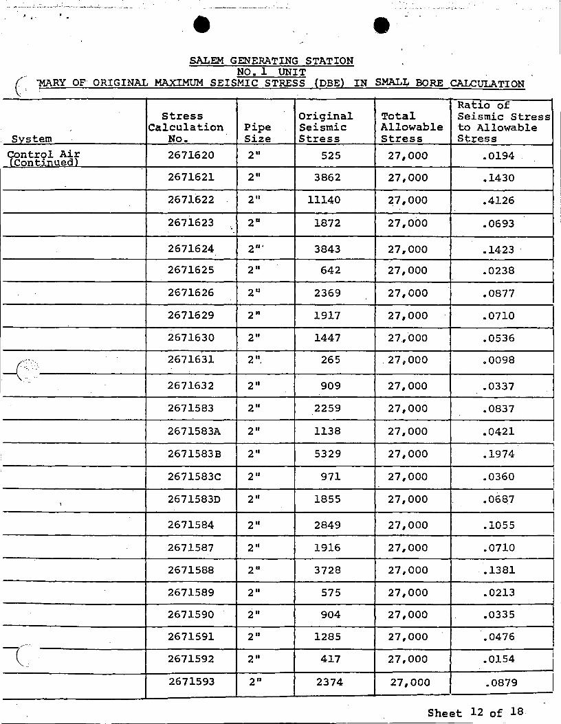
SALEM GENERATING STATION NO. 1 UNIT c·· ~RY OF ORIGINAL MAXIMUM SEISMIC STRESS (DBE) IN SMALI,. BORE CALCULATION
Ratio of Stress Original Total Seismic Stress
Calculation Pipe Seismic Allowable to Allowable Svstem No. Size Stress Stress Stress
9ontr9l ~~f 2671620 2 II Continue
525 27,000 .0194
2671621 211 3862 27,000 .1430
2671622 2 II 11140 27,000 .4126
2671623 ·. 211 1872 27,000 .0693
2671624 211 · 3843 27,000 .1423
2671625 2 II 642 27,000 .0238
2671626 211 2369 27,000 .0877
2671629 2 II 1917 27,000 .0710
2671630 2 II 1447 27,000 .0536
~~-~·-· 2671631 2 11_ 265 .27,000 .0098
2671632 2 II 909 27,000 .0337
2671583 2 II 2259 27,000 .0837
2671583A 2 II 1138 27,000 .0421
2671583B 2 II 5329 27,000 .1974
2671583C 2 II 971 27,000 .0360
, 2671583D 2 II 1855 27,000 • 068.7
2671584 2 II 2849 27,000 .1055
2671587 211 1916 27,000 .0710
2671588 2 II 3728 27,000 .1381
2671589 211 575 27,000 .0213
2671590 2 II 904 27,000 .0335
2671591 2 II 1285 27,000 .0476 -c 2671592 2 II 417 27,000 .0154
2671593 211 2374 27,000 .0879
Sheet 12 of 18
I I
'
i
. ·-'- - ... : ... ..... ,. ..... ..: __
JI : ~
SALEM GENERATING STATION · · NO. 1 UNIT
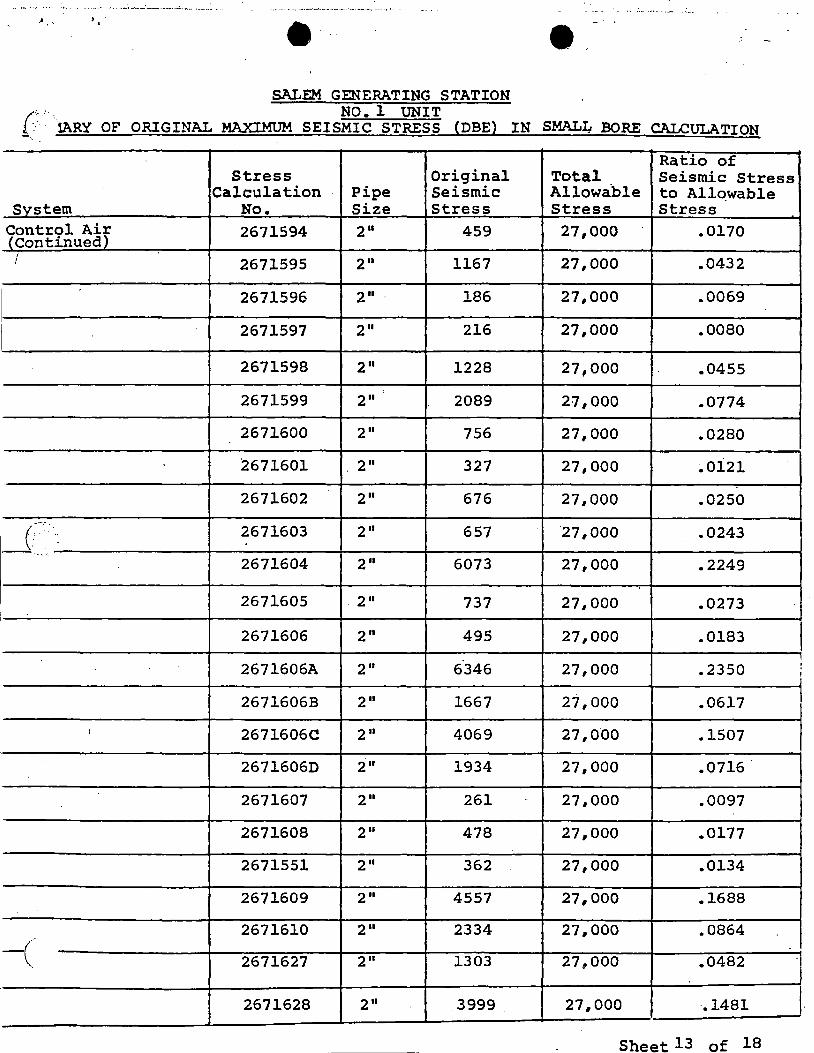
{;: .. ,1ARY OF ORIGINAL MAXIMUM SEISMIC STRESS (DBE} IN SMALI.i BORE CALCULATION
Ratio of Stress Original Total Seismic Stress
Calculation Pipe Seismic Allowa.ble to Allo.wable Svstem No. Size Stress Stress Stress
Control Aiy lcontinued
2671594 2" 459 27,000 .0170 I I 2671595 2" 1167 27,000 .0432
2671596 2 II 186 27i000 .. 0069
2671597 2 II 216 27,000 .0080
2671598 2" 1228 27,000 .0455
2671599 211 2089 27,000 .0774
2671600 2" 756 27,000 .0280
2671601 , 2 II 327 27,000 .oi21
2671602 211 676 . 27 I 000 .0250
c:·:· 2671603 2 II. 657 ·27 I 000 .0243 -····
2671604 2 II 6073 27,000 .2249
2671605 . 2 II 737 27,000 .0273 i
2671606 2 II 495 27,000 .0183 I I
2671606A 2 II 6346 27,000 .2350 '
2671606B 211 1667 27,000 .0617
: 2671606C 2 II 4069 27,000 .1507
2671606D 211 1934 27,000 .0716
2671607 2 II 261 - 27,000 .0097
2671608 2" 478 27,000 .0177
2671551 2 II 362 27,000 .0134
2671609 2 II 4557 27,000 .1688
2671610 2 II 2334 27,000 .0864 ..
-( 2671627 211 1303 27,,000 .0482
2671628 2 II 3999 27,000 ·.1481 I Sheet 13 of 18
' -·~ -.- " - - ~ . ~: .. ,--'... ..... ·-··-· -~ .. ~·
,. .: l' l . ~· . -
SALEM GENERATING STATION NO. 1 UNIT
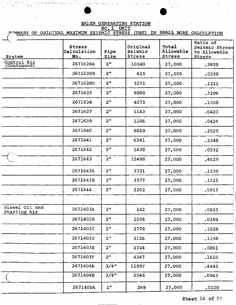
e _f_C'!.""lv'JMARY OF ORIGINAL MAXI.MUM SEISMIC STRESS (DBE) IN SMALI,. BORE CALCULATION
-- . Ratio of Stress Original Total Seismic Stress
Calculation Pipe Seismic Allowable to Allowable vs tern No. Size Stress Stres-s Stress
1ontrQl Air Continued 2671628A 2 II 10340 27,000. .3829
2671628B 211 615 27,000 .0228
2671628C 211 3271 27,000 .1211
2671633 2 II 8900 27,000 .3296
2671634 2 II 4073 27,000 .1508
2671637 2 II 1143 27,000 .0423
2671639 2 II 1146 27,000 .0424
2671640 2 II 6819 27,000 .2525
2671641 2 II 6341 27,000 .2348
2671642 2 II 1438 27,000 .0532 -(·._ · ..
2671643 2 II 12498 27,000 .4629 ,_, ..
2671643A 2 II 3321 27,000 '
.1230
2671643B 2 II 3577 27,000 .1325
2671644 211 2202 27,000 .0815
Diesel Oil and Startinq Air 2671403A 211 142 27,000 .0053
2671403B 211 1036 27,000 .0384
2671403C 2 II 2776 27,000 .1028
2671403D 211 3126 27,000 .1158
2671403E 2" 2324 27,000 .0861
2671403F 2" 4347 27,000 .1610
2671404A 3/4 11 11997 27,000 ·.4443
( 2671404B 3/4 11 2545 27,000 .0943
2671405A 111 269 27,000 .0100
Sheet 14 of Jr,·
I ' I ! i I I I I I
I I I
I \
i !
i i
'
'
L
l .! I t
SALEM GENERATING STATION NO. l UNIT
_(c:~.~y OF ORIGINAL MAXIMUM SEISMIC STRESS (DBE) IN SMALI,. BORE CALCULATION
. -Ratio of -··
Stress Original Total Seismic Stress Calculation Pipe Seismic Allowable ;to Allowable
Svstem No. Size Stress Stress Stress
Dieset Oil.& S~trtin~ Air - Continue 2671405B l" 10214· 27,000 .3783
2671406 3/4" 2105 27,000 .0780
2671406A 1-1/2" 5571 27,000 .2063
2671406B 1-1/2" 4061 27,000 .1504
2671406C 1-1/2 11 . 1514 27,000 .0561
26714060 3/4 11 10491 27,000 .3885
2671406E 3/4 11 1283 27,000 .0475
2671406F 3/4" 402 27,000 .0149
2671406G 3/4 11 135 27,000 .OQ50
2671406H 3/4 11 254 27,000 .0094 "i?·-·., .. . ·.· .. :·.-·.
"-· . 2671408 2 II 198 27,000 .0073
2671408A 2" 502 27,000 .0186
2671408B l" 443 27,000 .0164
2671409 1-1/2" 4263 27,000 .1579
2671409B 1-1/2 11 3701 27,000 .1371
2671409DA 3/4 11 6109 27,000 .2263 '
2671410B l" 1283 27,000 .0475
2671410C 3/4" 1695 27,000 .0628
26714100 2 II 1212 27,000 .0449
2671410E 2" 377 27,000 .0140
2671410F 1-1/2 11 280 27,000 .0104
(. Tice Water 267747C 2" 690 24,750 .0278
2677470 3/4 11 4304 24,750 .17-39•
Sheet 15 - of 18
------
l
j i
i
Jo • r J I
SALEM GENERATING ST.ATION NO. 1 UNIT
SUMMARY OF ORIGINAL MAXI.MUM SEISMIC STRESS (DBE) IN SMAL~ BORE CALCULATION ( -'"- .. Ratio of
Stress Original Total Seismic Stress Calculation Pipe Seismic Allowable to Allowable
Svstem No. Size Stress Stres·s Stress -
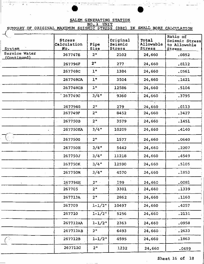
Service Water 267747E 2 II 2102 24,660 .0852 f ~n,, r i,, 11~n)
267794F z .. 277. 24,660 .0112
267748C 111 1384 24,660 .0561
267748CA l" 3504 24,660 .1421
267748CB 111 12586 24,660 .5104
I 267749C 3/4 11 9360 24,660 .3795
-267794G 2 ii 279 24,660 .0113
267749F 2 II 8452 24,660 .3427
267750B 2" 3579 24,660 .1451
. 267750EA 3/4 11 10209 24,660 .4140 (-...
'<·: 267750G 2 II 1577 24,660 .0640
267750H 3/4 11 5442 24,660 .2207
267750J 3/4" 11218 24,660 .4549
267750K 3/4 11 12590 24,660 .5105
267750M 3/4" 4570 24,660 .1853
" 267794H 2" 199 24,660 .0081
267705 211 3301 24,660 .1339
267713A 211 2862 24,660 .1160
267709 1-1/2 II 10497 24,660 .4257
267710 1-1/2 11 5256 24,660 .2131
267712AA 1-1/2 11 2363 24,660 .0958
267712AB 2 II 6493 24, 660 . .2633 ..
( 267712B 1-1/2" 4595 24,660 .1863 .-.. ..
267712C 2 II 1232 24,660 .0499
Sheet 16 of 18
i
I '
i
.. .. · -··-·· .__, .. . .. ....... ~ ~ ...... , -·. _,.·.,___.,-:;...~---·,, ___ .; _________ - ····~- 4·----~----::~ .. - •·--·-- ....... _· - ......... '···' -- .. -- ...... ·---·--· ''"' .. • .. , ' . ... . . . . . - ~. -. . .. .. ··-·- .. ., e -· e -
SALEM GENERATING STATION NO. 1 UNIT
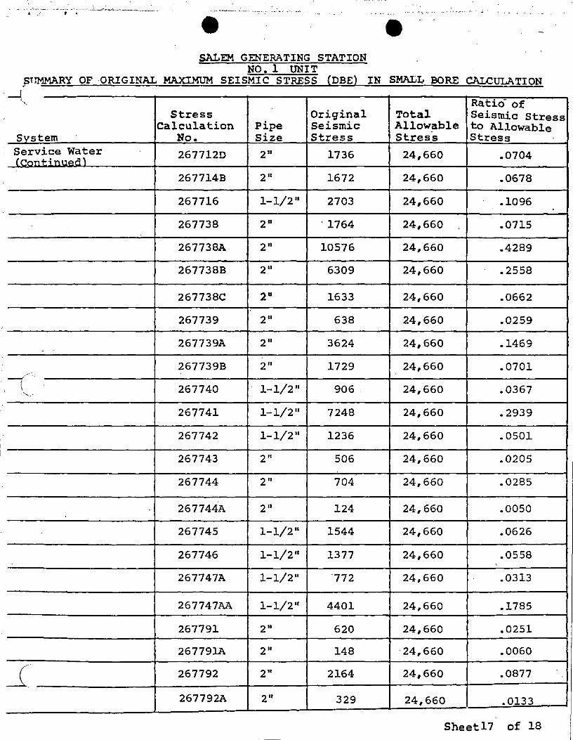
~lrMMARY OF ORIGINAL MAXIMUM SEISMIC STRESS {DBE} IN SMALL BORE CALCULATION
-! '•, Ratio- of
Stress Original Total Seismic Stress Calculation Pipe Seismic Allowable to Allowable
Svstem No. Size Stress Stress Stress Service water 2677120 2" 1736 24,660 .0704 (C!nnt-i nu""n)
267714B 2" 1672 24,660 .0678
267716 1-1/2 11 2703 24,660 .1096
267738 2 II '1764 24,660 .0715
267738A 2 II 10576 24,660 .4289
267738B 2 II 6309 24,660 .2558
267738C 211 1633 24,660 .0662
267739 2 II 638 24,660 .0259
267739A 211 3624 24,660 .1469 -
267739B 211 1729 24,660 .0701
( 267740 1-1/2 11 906. 24,660 .0367 ., __ ,
267741 1-1/2 11 7248 24,660 .2939
267742 1-1/2 11 1236 24,660 .0501
267743 2" 506 24,660 .0205
267744 2". 704 24,660 .0285
267744A 2" 124 24,660 .0050 •.
267745 1-1/2 11 1544 24,660 .0626
267746 1-1/2 11 1377 24,660 .0558
267747A 1-1/2 11 ·772 24,660 .0313
267747AA 1-1/2 11 4401 24,660 .1785
267791 211 620 24,660 .0251
267791A 2" 148 . 24, 660 .0060
-1: 267792 211 2164 24,660 .0877
267792A 2 II 329 24,660 .0133
Sheetl7 of 18 -
••
SALEM GENERATING STATION NO. l lJNIT
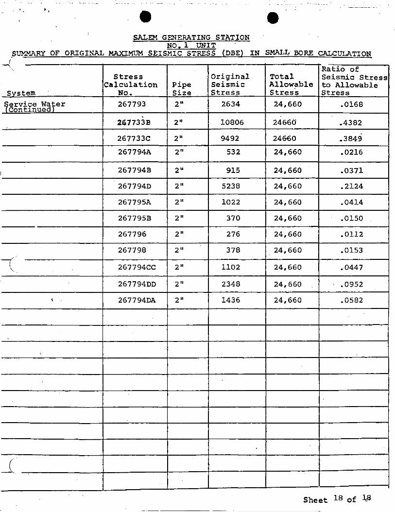
.SUMMARY OF ORIGINAL MAXIMUM SEISMIC STRESS (DBE) IN SMALL BORE CALCULATION (
-1 Ratio of
Stress Original Total Seismic Stress Calculation Pipe Seismic Allowable to Allowable
System No. Size Stress Stress Stress
~ervice wafer Continued
267793 2" 2634 24,660 .0168
267733B 2" 10806 24660 .4382
-.267733C 2" 9492 24&60 .3849
-267794A 211 532 24,660 .0216
I 267794B 2" 915 24,660 .0371
2677940 2 II 5238 24,660 .2124
267795A 2 II 1022 246660 .0414
267795B 2 II 370 24,660 .0150
267796 2 II 276 24,660 .0112
267798 2 II 378 24,660 .0153 " ,.
·-i 267794CC 2 II 1102 24,660 .-044 7 '--
I 267794DD 2 II 2348 24,660 .0952
' 267794DA 2 II 1436 24,660 .0582
'
.,
( -'--
Sheet 18 of 1-8
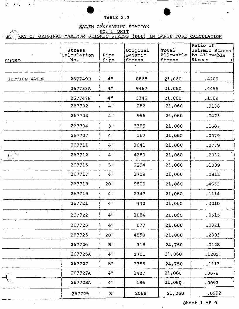
.. . ' . ' TABLE 2. 2
' 51'..LE."1 GENERATING STATION
s{~:·:; :~RY OF ORIGINAL MAXIMUM SEIS:~c ~T:~~ (DBE) IN LARGE BORE CALCULATION
Ratio of Stress Original Total Seismic Stress
Calculation Pipe Seismic Allowable to Allowable ;vs tern No. Size Stress Stress Stress I
-
SERVICE WATER 267749E 411 8865 21,060 .4209
267733A 4u 9467 21,060 .4495
267747F 411 3346 21,060 .1589
267702 411 286 21,060 .0136 . ..
267703 411 996 21,060 .0473
I 267704 311 3385 21,060 .1607
267707 411 167 21,060 .0079
267711 411 1641 21,060 .077°9
(. . -~:: I 267712 411 4280 ·21, 060 .2032 .--..
267715 311 2294 21,060 .1089
I 267717 411 1709 21,060 .0812
267718 20 11 9800 21,060 .4653
267719 411 2347 21,060. .1114
267721 411 442 21,060 .0210
' 267722 411 1084 21,060 .0515
267723 411 677 21,060 .0321
267725 20 11 4850 21,060 .2303
267726 911 318 24,750 .0128
267726A 411 2701 21,_06.Q .12Sl .. ! j
267727 911 2755 24,750 .1113 I
267727A 411 1427 21,060 .0678 I
--(~-· 267728A 411 196 21,..0GQ · .0093
267729. 8" 2089 21,060 .0992
Sheet 1 of 9
-- - - -
-~ .. ·--· -··-·--'-•·--'--~-...:~ . .._...;_...__~-· ·--'--"~"-------· ·--'··--· .. -~·-· - ·'-----·- ·--· - --··· . - ... , -·-· _, __ - _,_ c. ••
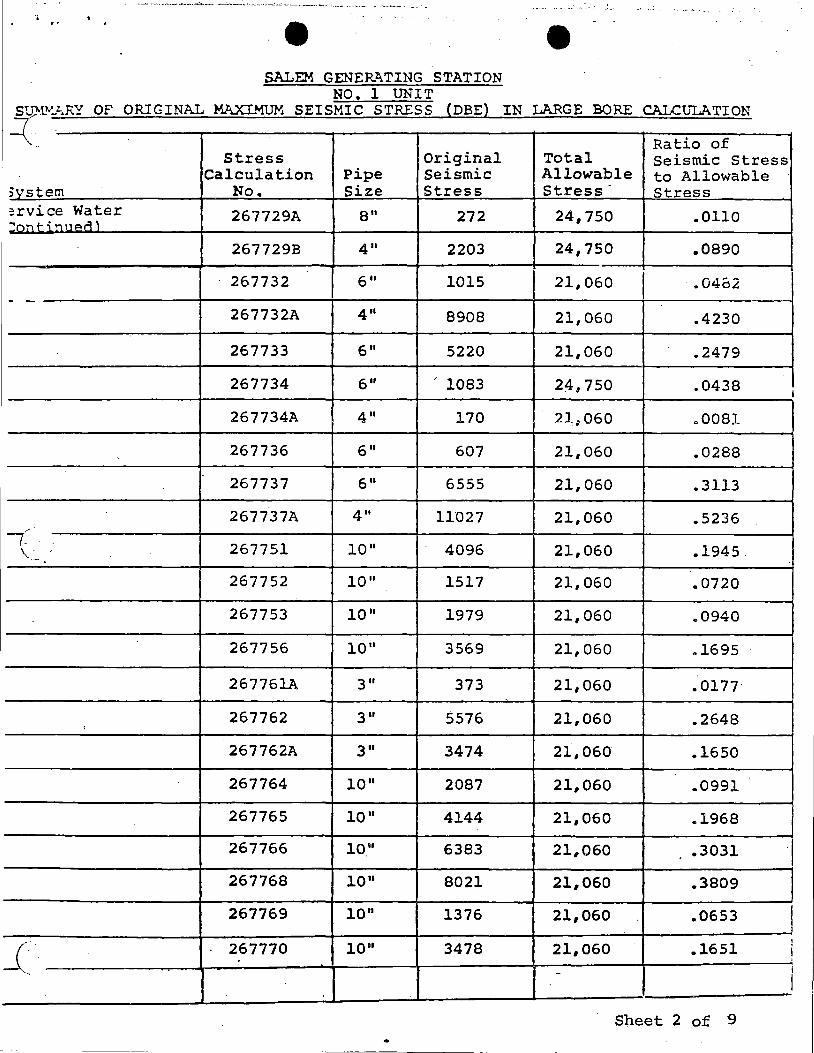
-~ • -,. ' e e --
SALEM GENER.?.. TING STATION NO. 1 UNIT
Su)'.11"-z..RY OF ORIGINAL MAXIMUM SEISMIC STRESS {DBE) IN LARGE BORE CALCu"LA TI ON
~-.. Ratio of
Stress Original Total Seismic Stress Calculation Pipe Seismic Allowable to Allowable
No. Size Stress Stress - Stress ;vs tern :rvice Water 267729A 8" 272 24,750 .0110 ~!"'IT\ t- i., n or'l'
267729B 411 2203 24,750 .0890
267732 6" 1015 I 21,060 I .• 04fa2 - -
267732A 4" 8908 21,060 .4230
267733 6" 5220 21,060 .2479
267734 611 1083 24,750 .0438 I
267734A 411 170 2lg060 00081
267736 6" 607 21,060 .0288
267737 6" 6555 21,060 .3113
267737A 4 II 11027 21,060 .5236 ,. -· (.
267751 10 11 4096 21,060 .1945. \ --
267752 10" 1517 21,060 .0720
267753 10 11 1979 21,060 00940
267756 10 11 3569 21,060 .1695
267761A 3 II 373 21,060 .0177
267762 3 II 5576 21,060 .2648 I
267762A 3 II 3474 21,060 .1650
267764 10 11 2087 21,060 .0991
267765 10 II 4144 21,060 .. 1968
267766 ion 6383 21,060 .3031 I 267768 10 11 8021 21,060 .3809
267769 10" 1376 21,060 .0653
.1651 I
_( 267770 10 11 3478 21,060 j '
- I
l
Sheet 2 of 9 .
~-- -- -----
. ' .. . -·------····--- _____ __:, ______ · ~~_.: _________ ;..,,._...., ___________ ._:.~ ----~ .. ___ ,, ____ ,___ ... ~ ........... ______ .,__, __ _
- .. - -··· - ...... ·- •·· -~---~-'-···'···-··-- ·-··-··---~-------~--""·~ .. -~-.. -~·-···-
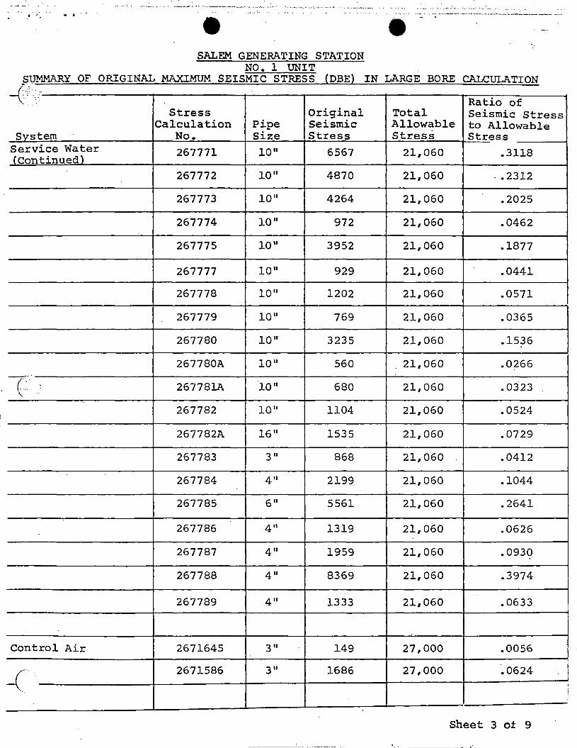
SALEM GENERATING STATION NO. 1 UNIT
SUMMARY OF ORIGINAL MAXIMUM SEISMIC STRESS (DBE) IN LARGE BORE CALCULATION ·
-( ,.
' Ratio of Stress Original Total Seismic Stress
Calculation Pipe Seismic Allowable to Allowable Svstem No. Size Stress Stress Stress
Service Water 267771 10 11 6567 21,060 .3118 <continued)
267772 10 11 4870 21,060 - • 2312
267773 ion 4264 21,060 .2025
267774 10 11 972 21,060 .0462
267775 10 11 3952 21,060 .1877
267777 10 11 929 21,060 .0441
267778 10 11 1202 21,060 .0571
267779 ion 769 21,060 .0365
267780 10" 3235 21,060 .1536
267780A 10 11 560 21,060 .0266
7":· 267781A 10 11 ,_ 680 21,060 .0323
267782 10 11 1104 21,060 .0524
267782A 16 11 1535 21,060 .0729
267783 3 II 868 21,060 .0412
267784 4" 2199 21,060 .1044
267785 6" 5561 21,060 .2641
267786 411 1319 21,060 .0626
267787 4" 1959 21,060 .0930
267788 411 8369 21,060 .3974
267789 411 1333 21,060 .0633
Control Air 2671645 3 II 149 27,000 .0056
~'··. 2671586 3" 1686 27,000 .0624
Sheet 3 of 9
I
I
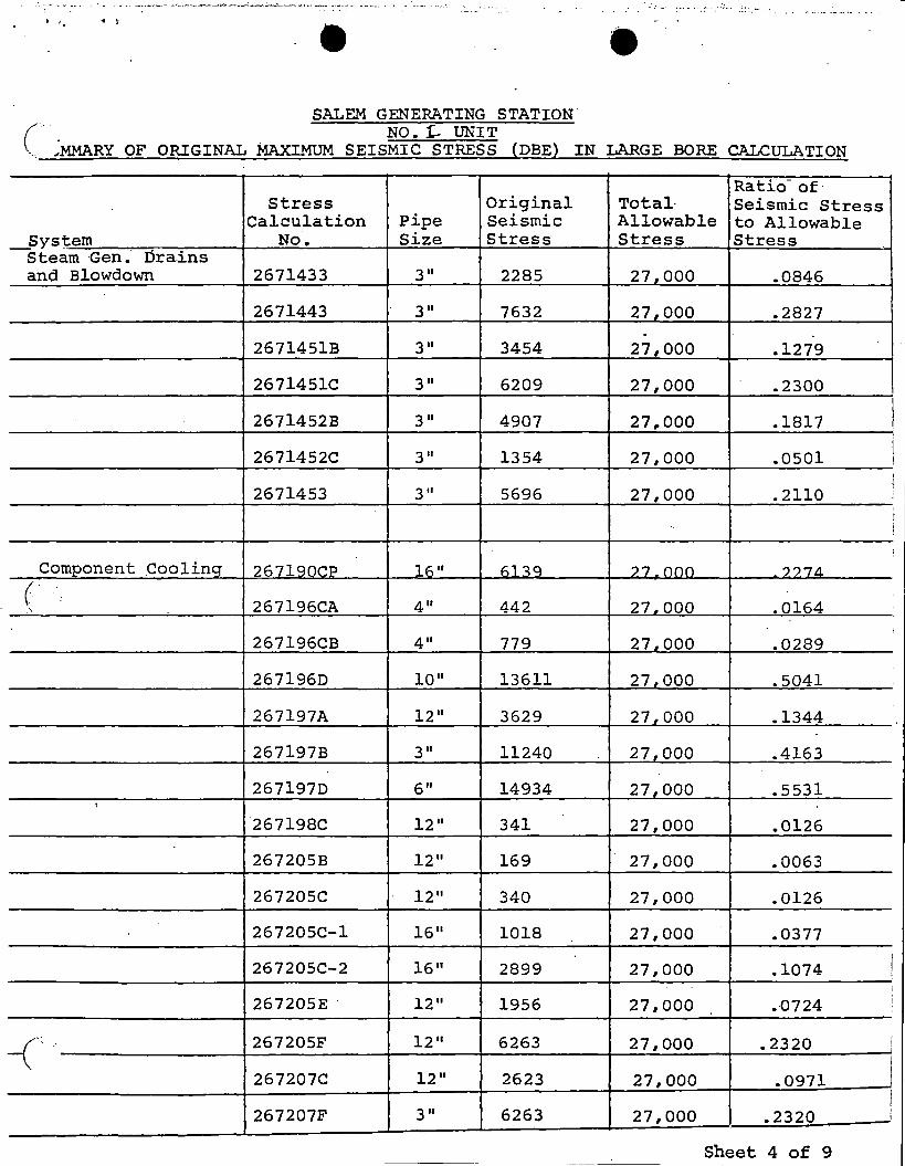
------ - -.. - - .. -- - . - - --- .... ~~-- -·---"---~- ............ ________ _.,__,.__, ___ ,~_ ---··-·-·-'- -- --- . . -· -- ··-~' ·-··· - .. ; _______ ·-·· . ·-··· .. - ..... ····· ..... ·- -- ··- ·~· - .... . ' "' "1 -e • SALEM GENERATING STATION. c· NO. 1- UNIT
OF ORIGINAL MAXIMUM SEISMIC STRESS (DBE} IN LARGE BORE CALCULATION ., ... M.MARY
Ratio of· Stress Original Total· Seismic Stress
Calculation Pipe Seismic Allowable to Allowable _Sys~em No. Size Stress Stress Stress
Steam Gen. Drains and Blowdown 2671433 3" 2285 27,000 .0846
2671443 3" 7632 27,000 .2827 .
2671451B 3" 3454 27,000 .1279
2671451C 3" 6209 27,000 .2300
2671452B 3 II 4907 27,.000 .1817
2671452C 3" 1354 27,000 .0501 I
2671453 3 II 5696 27,000 .2110 I i
! !
Component Coolinq 267l90CP 16 11 61~9 27.000 ??7'1
( 267196CA 4" 442 27.000 .0164 '
267196CB 4" 779 27.000 .0289
267196D 10 11 13611 27,000 .5041
267197A 12 11 3629 27,000 .1344 -
267197B 3" 11240 27,000 .4163
267197D 6" 14934 27,000 .5531 :
267198C 12" 341 27,000 .0126
267205B 12" 169 27,000 .0063
267205C 12" 340 27,000 .0126
267205C-i 16 11 1018 27,000 .0377
267205C-2 16 11 2899 27,000 .1074 I i
i
267205E · 12 11 1956 27,000 .-0724 i
-( 267205F 12" 6263 27,000 .2320 ' I
I 267207C 12 11 2623 27,000 .0971
I I
267207F 3 II 6263 27,000 .2320 i I
Sheet 4 of 9 -- --- -
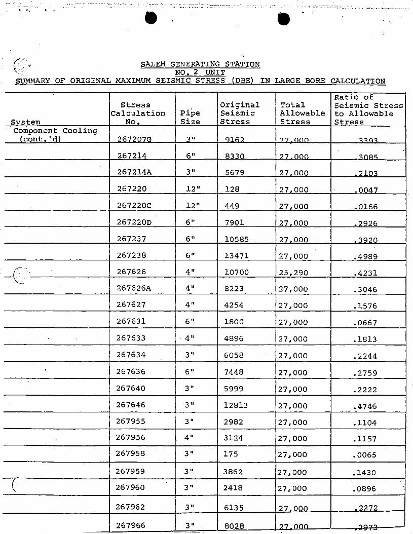
-~-------....-.: ...... .,_ .... -------·-"···---··-----~-. ·--.. ·-·· :.. -·-·····-- - .. -- ·~--.-: .. _ ~-.. ··---·-···· ..... . - : - :_ -;·· :::.:: ... ~·~:.:.::~ :·.:;·.'.::. : . : : . . ·.:... ....... _ . ..._, .. _ _,__..__. -· . . .. ----·-···-· -. .. ..,, ~ • •
('.'·.·,, SALEM GENERATING STATION - . . NO. 2 UNIT
SUMMARY OF ORIGINAL MAXIMUM SEISMIC STRESS (DBE) IN LARGE BORE CALCULATION
Ratio of Stress Original Total Seismic Stress
Calculation Pipe Seismic Allowable to Allowable Svstem No. Size Stress Stress Stress Component Cooling
{cont. 1 d) 267207G ':! II Qli:.? ')/ {'\()() ~~Q~
. 267214 611 8':! 10 ?7.000 ~nA"
267214A 3 II 5679 27.000 -210~
267220 12 11 128 27.000 .0047
267220C 12 11 449 27.000 .0166
267220D 611 7901 27.000 .2926
267237 611 10585 27.000 .3920
267238 611 13471 27.000 .4989
_(. 267626 411 10700 25,290 .4231 .. ··'.· . .. ...
. '-.c.:. 267626A 411 8223 27,000 .3046
267627 411 4254 27,000 .1576
267631 611 1800 27,000 .0667
267633 . 411 4896 27,000 .1813
267634 311 6058 27,000 .2244
I 267636 6" 7448 27,000 .2759
267640 311 5999 27,000 .2222
267646 311 12813 27,000 .4746
267955 311 2982 27,000 .1104
267956 411 3124 27,000 .1157
267958 311 175 27,000 .0065
267959 311 3862 27,000 .1430 -·. ( 267960 3 II 2418 27.,000 ~0896
267962 311 6135 27.000 ~2272
267966 3 II 8028 ? 7 (')(')() ..,,... ....... • -- I..,
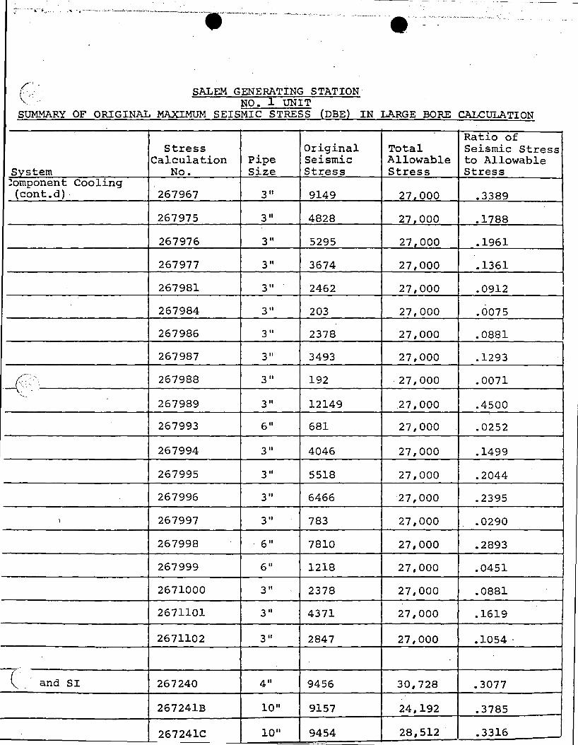
---- - -- - -- - -
.; ,_ --··\'.·· ....... ' ..... ._ _________ .,_, ___________ ,_~,--~------------.---~----·- .. - ---- ....... _,_ ·- -- . "' . ..... .. ·--·---"··- ~ . --- ·- ·: ----~-_,,._, ____ ··-·'""·-··· -··- -
('-· SALEM GENERATING STATION ... J. NO. UNIT
SUMMARY OF ORIGINAL MAXIMUM SEISMIC STRESS (DBE} IN LARGE BORE CALCULATION
Ratio of Stress Original Total Seismic Stress
Calculation Pipe Seismic Allowable to Allowable Svstem No. Size Stress Stress Stress ::!omponent Cooling {cont.d) - 267967 3 II 9149 27.000 .3389
267975 3 II 4828 27.000 .1788
267976 3" 5295 27,000 .1961
267977 3" 3674 27,000 .1361
267981 3" 2462 27r000 .0912
267984 3" 203 27,000 .0075
267986 311 2378 27,000 .0881
267987 3" 3493 27,000 .1293
-<-- ·_ 267988 3" 192 -27,000 .0071 '-···
267989 3" 12149 .27,000 .4500
267993 6" 681 27,000 .0252
267994 3" 4046 27,000 .1499
267995 311 5518 27,000 .2044
267996 311 6466 27,000 .2395
I 267997 3 II 783 27,000 .0290
267998 ' 611 7810 27,000 .2893
267999 6" 1218 27,000 .0451
2671000 311 2378 27,000 .0881
2671101 311 4371 27,000 .1619
2671102 311 2847 27,000 .1054 .
-z·_ and SI 267240 4" 9456 30,728 .3077
267241B 10 11 9157 24,192 .3785
267241C 10 11 9454 28,512 .3316
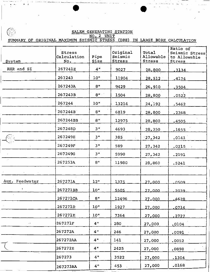
-- ----~-~- - ----- - -
·····--- ··--·. - . ---~~_, ____ ._ ..... ~ .. ..-t~--------·-~-•-•-4 .._ •.• r_, .•• _ •• __:.~,---~· Mo.•···~.••••·•·-"'"""·•• ··~··
·• ......... .. . - .. ,·. -- .~..: ~- _ _._ ...... __ c. ' - ....... ~-- ... 11. .. j e ' e --
G.·{;;~.':~ SALEM GENERATING STATION NO. 2 UNIT
SUMMARY OF ORIGINAL MAXIMUM SEISMIC STRESS {DBE} IN LARGE BORE CALCULATION
Ratio of Stress Original Total Seismic Stress
Calculation Pipe Seismic Allowable to Allowable Svstem No. Size Stress Stress Stress
RHR and SI 267241E 4" 9027 28.800 .3134 ..
267243 10 11 11904 28.512 .4174
267243A 911 9429 26.910 .3504 I
267243B 911. 1504 28,800 .0522
267244 10" 13214 24,192 .5462
267244B 8" 6819 28,800 .2368
267244BB 8" 12975 28,800 .4505
267248D 3 II 4693 28,350 .1655
__(·: .· ·- 267249E 311 385 ·27,342 .0141 ~--
267249F 3 II 589 27,342 .0215
267249G 311 5990 27,342 .2191
267253A 911 11980 28,860 .5241
Aux. Feedwater 267271A 12 11 1375 27 onn nc::na
I 267271BB 10" 55nc; 27.000 ?n<a
267271CA 911 12496 27.000 -46?R
267271D 10 11 1927 27.000 .0714
267271E 10 11 7364 27,000 .2727
.. 267271F 411 280 27,000 .0104
267272A 411 246 27,000 .0091
267272AA 4" 141 27,000 .0052 _,-·
( 267272E 411 2425 27,000 .0898
267273 411 3522 27,000 .1304
267273AA 411 453 27,000 .0168
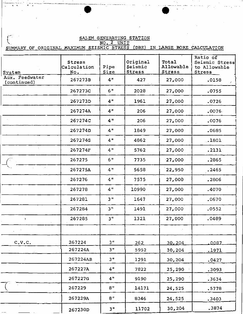
--~-J-·~-----~-~---·- ._ - .. - ... -~ ·-----~------~------.~----'--- . ··- ---------- -··-···
SALEM GENERATING STATION NO. 2 UNIT
SUMY.ARY OF ORIGINAL MAXIMUM SEISMIC STRESS (DBE) IN LARGE BORE CALCULATION
Ratio of Stress Original Total Seismic Stress
Calculation Pipe Seismic Allowable to Allowable System No. Size Stress Stress Stress Aux. Feedwater 267273B 411 427 27,000 .0158 (continued) /
267273C 6 II 2028 27,000 .0755
267273D 411 1961 27,000 .0726
267274A 4" 206 27,000 .0076.
267274C 411 206 27,000 .0076
2672740 411 1849 27,000 .0685
267274G 4 II 4862 27,000 , .1801
267~74F 411 5762 27,000 .2131
_J-:· 267275 6" 7735 ·27, 000 .2865
'- ...
267275A 411 5658 22,950 .2465
267276 4" 7575 27,000 .2806
267278 4" 10990 27,000 .4070
267281 3 II 1647 27,000 .0670
267284 3 II 1491 27,000 .0552
l 267285 3" 1321 27,000 .0489
c.v.c. 267224 3" 262 30.204 ()()R7
267224A 3" 5952 30,204 .1971
267224AB 3" 1291 30,204 .0427
267227A 4" 7822 25,290 .3093
267227G 4" 9190 25,290 .3634 -c· 267229 8" 14171 24,525 .5778
267229A 8" 8346 24,525 .3403
2672300 311 11702 30,204 .3874 --- -
-
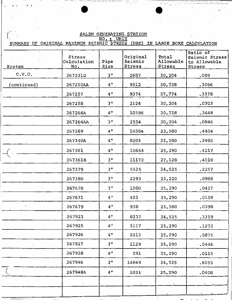
'···-·· . - ··-·-'-··-~,.·--- .__ _____ ·- , ________ ..... . ..... . ..-.(:: •" -- .. ··~ '-·· . _._,__ ..... .
-· -·-. . ... ····· ·-·---~---·· . ······-·-~- ··-- -·---·---- ~--,_
( SALEM GENERATING STATION NO. l UNIT
SUMMARY OF ORIGINAL MAXIMUM SEISMIC STRESS (DBE) IN LARGE BORE CALCULATION
Ratio of Stress Original Total Seismic Stress
Calculation Pipe Seismic Allowable to Allowable System No. Size Stress Stress Stress
c.v.c. 267231D 3" 2687 30,204 .089
(continued) 267250AA 4" 9512 30.,728 .3096
267257 4" 9374 27,774 .3378
267258 3" 2124 30,204 .0703
267264A 4" 10596 30,728 .3448
267264AA 3" 2554 30,204 .0846
267269 4" 10384 23,580 .4404
267340A 4" 8205 23,580 .3480
_( ,.
267361 4" 10664 25,290 .4217
' 267361B 3" 11172 27,128 .4118
267379 3" 5535 24,525 .2257
I 267380 3 II 2293 23,220 .0988
'
267670 3" 1080 25,290 .0427 I
267671 4" 403 25,290 .0159
; 267679 4" 938 23,580 .0398
267922 4" 8237 24,525 .3359
267925 4" 3117 25,290 .1272
267926 4" 2213 25,290 .0875
267927 3" 11~9 25,290 .0446
267928 4" 291 25,290 .0115
267946 3" 14849 24,525 .6055 .. -· ( 267948A 4" 1031 25,290 .0408
- - - -
. ,.
_..___ - - t. - - .r """'
( ,_
9Sl 05
·PUBLIC SERVICE ELECTRIC AND GAS COMPANY ENGINEERING AND CONSTRUCTION DEPARTMENT
"Procedure for evaluating Pipe Support Capabilities at Salem Nuclear Generating Station.
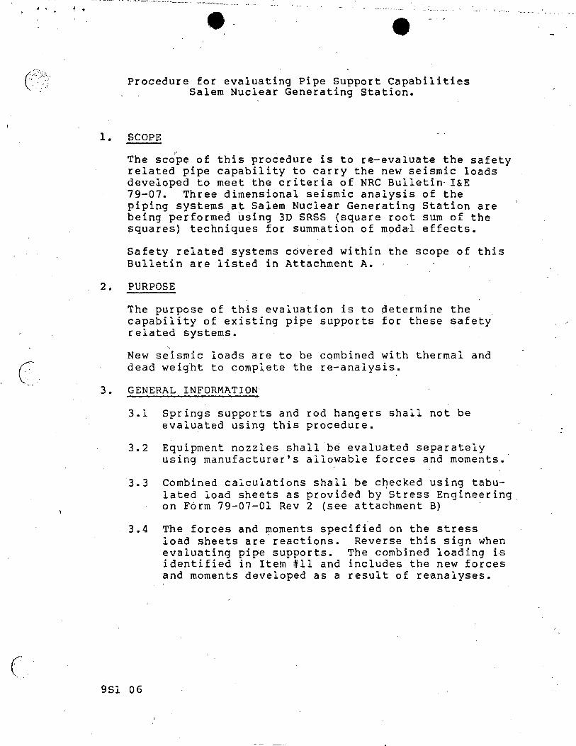
. .
(.
1.
Procedure for evaluating Pipe Support Capabilities Salem Nuclear Generating Station.
SCOPE
The sc~~e of this procedure is to re-evaluate the safety related pipe capability to carry the new seismic loads developed to meet the criteria of NRC Bulletin· I&E 79-07. Three dimensional seismic analysis of the piping systems at Salem Nuclear Generating Station are being performed ~sing 3D SRSS (square root sum of the squares) techniques for summation of modal effects.
Safety related systems covered within the scope of this Bulletin are listed in Attachment A. ·
2. PURPOSE
3.
The purpose of this evaluation is to determine the capability of existing pipe supports for these safety related systems.
~
New seismic loads are to be combined with thermal and dead wei~ht to complete the re-analysis.
GENERAL INFORMATION
3.1 Springs supports and rod hangers shall not be evaluated using this procedure.
3.2 Equipment nozzles shall be evaluated separately using manufacturer's allowable forces and moments.
3.3 Combined calculations shall be c~ecked using tabulated load sheets as provided by Stress Engineering on F6rm 79-07-01 Rev 2 (see attachment B)
3.4 The forces and moments specified on the stress load sheets are.reactions. Reverse this sign when evaluating pipe supports. The combined loading is identified in Item #11 and includes the new forces and moments developed as a result of reanalyses.
9Sl 06
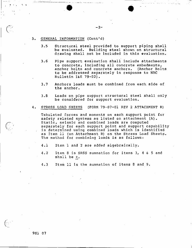
(-:.:;··.;
..
:.-
~--( ·.
\: .
c··.
3.
.e
-2-
GENERAL INFORMATION (Cont'd)
3.5 Structural steel provided to support piping shall be evaluated. Building steel shown on structural drawing shall not be included in this evaluation.
3.6 Pipe support evaluation shall include attachments to concrete, including all concrete embedments, anchor bolts and concrete anchors. (Anchor Bolts to be addressed separately in response to NRC Bulletin I&E 79-02).
3.7 Anchors loads must be combined from each. side of the anchor.
3.8 Loads on pipe support structural steel shall. only be considered for support evaluation.
4. STRESS LOAD SHEETS (FORM 79-07-01 REV 2 ATTACHMENT B)
Tabulated forces and moments on each support point for safety related systems as listed on attachment (A). Static, seismic and combined loads are computed separately for each support point and support capability is determined using combined loads which is identified as Item 11 (on Attachment B) on the Stress Load Sheets. The method for combining loads is as follows:
4.1 Item l and 2 are added algebraically.
4.2 Item 8 is SRSS summation for items 3, 4 & 5 and shall be +.
4.3 Item 11 is the summation of items 8 and 9.
9Sl 07
_j
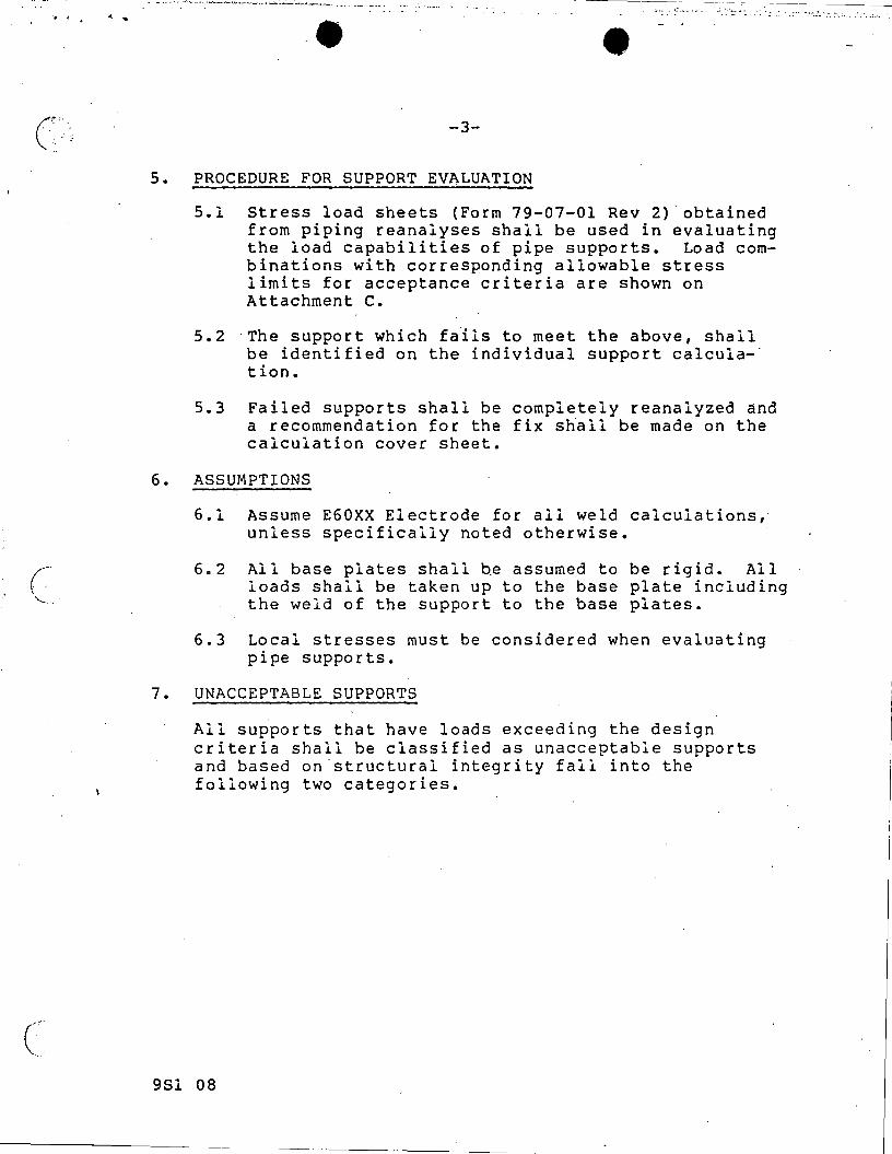
. , . ..
(~ '-... ...
c-
s.
--------
-3-
PROCEDURE FOR SUPPORT EVALUATION
5.1 Stress load sheets (Form 79-07-01 Rev 2)-obtained from piping reanalyses shall be used in evaluating the load capabilities of pipe supports. Load combinations with corresponding allowable stress limits for acceptance criteria are shown on Attachment c.
5.2 The support which fails to meet the above, shall be identified on the individual support calculation.
5.3 Failed supports shall be completely reanalyzed and a recommendation for the fix shall be made on the calculation cover sheet.
6. ASSUMPTIONS
6.1 Assume E60XX Electrode for all weld calculations, unless specifically noted otherwise.
6.2 All base plates shall be assumed to be rigid. All loads shall be taken up to the base plate including the weld of the support to the base plates.
6.3 Local stresses must be considered when evaluating pipe supports.
7. UNACCEPTABLE SUPPORTS
All supports that have loads exceeding the design criteria shall be classified as unacceptable supports and based on.structural integrity fall into the following two categories.
9Sl 08
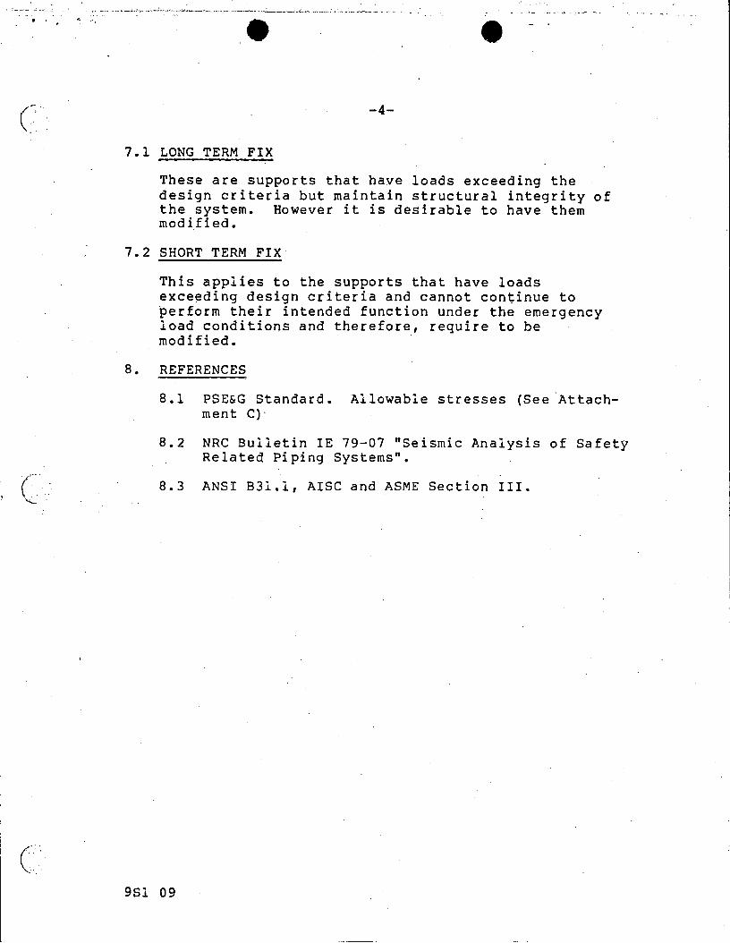
------ -----
(-· .-.
-·.
(" '~-
c·-
--·- ... __:_,_., - __ . _ ____:. __ ,_~ -~~---<!-~~- ........ ~.......,-~~ ~----...'--'-~··-'-"-~--~-· ---··-----; ~.: ... ~ -"-·- -~---- ~~ ·-- - ~- , - ---
-4-
7.1 LONG TERM FIX
These are supports that have loads exceeding the design criteria but maintain structural integrity of the system. However it is desirable to have them modified.
7.2 SHORT TERM FIX
This applies to the supports that have loads exceeding design criteria and cannot continue to perform their intended function under the emergency load conditions and therefore, require to be modified.
8. REFERENCES
8.1 PSE&G Standard. Allowable stresses (See Attachment C) ·
8.2 NRC Bulletin IE 79-07 "Seismic Analysis of Safety Related Piping Systems".
8.3 ANSI B31.l, AISC and ASME Section III.
9Sl 09
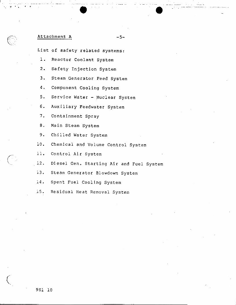
--~----------------------:--------- -- ---
.•.
Attachment A -5-
List of safety related systems:
l. Reactor Coolant System
2. Safety Injection System
3. Steam Generator Feed System
4. Component Cooling System
5. Service W~ter - Nuclear System
6. Auxiliary Feedwater System
7. Containment Spray
8. Main Steam System
9. Chilled Water System
10. Chemical and Volume Control System
~~. Control Air System
12. Diesel Gen. Starting Air and Fuel System
13. Steam Generator Slowdown System
14. Spent Fuel Cooling System
15. Residual Heat Removal System
( 9Sl 10
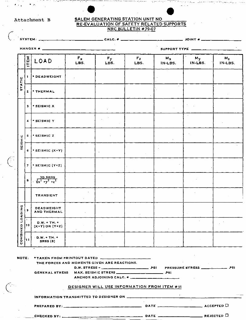
I_
r~-, .. --- .
·--· -- • -··.-.; ••• :!-··-- .·
.e ~ttachment B SALEM GENERATING STATION UNIT NO
RE-EVALUATION OF SAFETY RELATED SUPPORTS NRC BULLETIN #79-07
SYSTEM: ---------------CALC. # -------------- JOINT#---------
HANGER # ----------------- SUPPORT TYPE
:E LOAD Fx Fy Fz Mx My -Mz Lr.I LBS. LBS. LBS. IN-LBS . IN-LBS. IN-LBS. .... -
u I • DEADWEIGHT -
I-< I-UI z *THERMAL
3 *SEISMIC X
4 *SEISMIC Y
!::! s *SEISMIC Z
~ !:!! LI.I Ul
6 *SEISMIC (X+Y)
7 *_SEISMJC (Y+ZJ
30 SRSS 8 .Jx2 +y2 +z2
TRANSIENT
Cl DEADWEIGHT z 9 AND THERMAL c
c(
0 ' .J D.W. +TH.+ c 10 (X+Y) OR (Y+Z) LI.I z m ~ · D.W. +TH.+ 0 11 SRSS (8) u
NOTE: •TAKEN FROM PRINTOUT DATED
THE FORCES ANO MOMENTS GIVEN ARE REACTIONS.
D.W. STRESS=----------- .PSI PRESSURE STRESS---'----- .PSI
GENERAL STRESS MAX. SEISMIC STRESS ___________ .PSI
ANCHOR ADJOINING CAL.C. # -----------
DESIGNER WILL USE INFORMATION FROM ITEM #11
INFORMATION TRANSMITTED TO DESIGNER ON --------------------------
PREPARED BY:------------------ DA TE ---------- ACCEPTED 0
_ __ __:CHECKED BY: ---......,.:================:_:D:_-A:_T_:__:E_.:._-:-:-:-=:-:-=-=-=-=-=-=-=-=-=-=-=-=-- REJECTED 0
I I
!
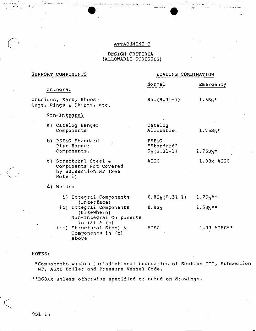
JI ,
(· "'···
,,. ..... ( \ .
"'·
';
'""
ATTACHMENT C
DESIGN CRITERIA (ALLOWABLE STRESSES)
SUPPORT COMPONENTS LOADING COMBINATION
Integral
Trunions, Ears, Shoes· Lugs, Rings & Skirts, etc.
Non-Integral
a) Catalog Hanger Components
b) PSE&G Standard Pipe Hanger Components.
c) Structural Steel & Components Not Covered by Subsection NF (See Note 1)
d) Welds:
Normal
Sh. (B.31-1)
Catalog Allowable
PSE&G "Standard" Sh ( B. '31-1)
AISC
i) Integral Components O.BSh(B.31-1) (Interface)
ii) Integral Components 0.8Sh (Elsewhere)
Non-Integral Components in (a) & (b)
iii) Structural Steel & AISC Components in (c) above
NOTES:
Emergency
l.75Sh*
l.75Sh*
l.33x AISC
l.2Sh**
l.5Sh**
1.33 AISC**
*Components within jurisdictional boundaries of Section III, Subsection NF, ASME Boiler and Pressure Vessel Code.
**EGOXX Unless otherwise specified or noted on drawings.
9Sl 15
--------