san diego county bmp design manual · county of san diego bmp design manual. effective february 26,...
TRANSCRIPT
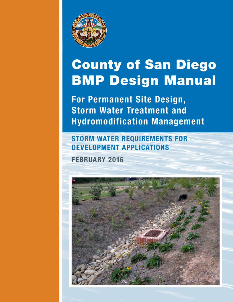
For Permanent Site Design,Storm Water Treatment andHydromodification Management
STorM WaTer requireMenTS For DeveloPMenT aPPlicaTionS
February 2016
County of San Diego BMP Design Manual

Effective February 26, 2016
This page was intentionally left blank.

Effective February 26, 2016
This page was intentionally left blank.

County of San Diego BMP Design Manual
i Effective February 26, 2016
Summary In May 2013, the California Regional Water Quality Control Board for the San Diego Region reissued (SDRWQCB) a municipal storm water, National Pollutant Discharge Elimination System permit (Municipal Separate Storm Sewer Systems [MS4] Permit) that covered its region. The San Diego Region is comprised of San Diego, Orange, and Riverside County Copermittees. The MS4 Permit reissuance to the San Diego County Copermittees went into effect in May 2013 (Order No. R9-2013-0001).
The reissued MS4 Permit updates and expands storm water requirements for new developments and redevelopments. The MS4 Permit was amended on February 11, 2015 by Order R9-2015-0001, and again on November 18, 2015 by Order R9-2015-0100. As required by the reissued MS4 Permit, the Copermittees prepared the Model Best Management Practices (BMP) Design Manual to replace the current Countywide Model Standard Urban Stormwater Mitigation Plan (SUSMP), dated March 25, 2011, which was based on the requirements of the 2007 MS4 Permit. This County of San Diego BMP Design Manual (“Manual”) modifies the content of the Model BMP Design Manual to include County-specific guidelines and requirements.
What this Manual is intended to address:
This Manual addresses, and provides guidance for complying with, updated post-construction storm water requirements for Standard Projects and Priority Development Projects (PDPs), and provides updated procedures for planning, preliminary design, selection, and design of permanent storm water BMPs based on the performance standards presented in the MS4 Permit and the County Watershed Protection Ordinance (WPO).
The intended users of this Manual include project applicants, for both private and public developments, their representatives responsible for preparation of Storm Water Quality Management Plans (SWQMPs) and County personnel responsible for review of these plans and associated documents.
The following are significant updates to storm water requirements of the MS4 Permit compared to the 2007 MS4 Permit and 2011 Countywide Model SUSMP:
• PDP categories have been updated, and the minimum threshold of impervious area to qualify as a PDP has been reduced.
• Many of the low impact development (LID) requirements for site design that were applicable only to PDPs under the 2007 MS4 Permit are applicable to all projects (Standard Projects and PDPs) under the MS4 Permit.
• The standard for storm water pollutant control (formerly treatment control) is retention of the 24-hour 85th percentile storm volume, defined as the event that has a precipitation total greater than or equal to 85 percent of all daily storm events larger than 0.01 inches over a given period of record in a specific area or location.
• For situations where onsite retention of the 85th percentile storm volume is technically not feasible, biofiltration must be provided to satisfy specific “biofiltration standards”. These standards consist of a set of siting, selection, sizing, design and maintenance criteria that

County of San Diego BMP Design Manual
ii Effective February 26, 2016
must be met for a BMP to be considered a “biofiltration BMP” – see Section 2.2.1 and Appendix F.
• Exemptions from hydromodification management are reduced, and certain categories of exemptions that are not explicitly identified in the MS4 Permit must be identified in a Watershed Management Area Analysis (WMAA).
• The flow control performance standard for hydromodification management is based on controlling flow to pre-development conditions (natural) rather than pre-project conditions.
• The flow control performance standard is updated. The requirement to compare flow frequency curves is removed. The performance standard for comparing pre-development and post-project flow duration curves is revised.
• Hydromodification management requirements are expanded to include requirements to protect critical coarse sediment yield areas.
• Alternative (offsite) compliance approaches are provided as an option to satisfy pollutant control or hydromodification management performance standards. Project applicants may be allowed to participate in an offsite alternative compliance program without demonstrating technical infeasibility of retention and/or biofiltration BMPs onsite. In such case, they must also provide flow-thru treatment control BMPs on the project site. Guidance on offsite alternative compliance options is provided in Appendix J.
What this manual does not address:
This Manual provides technical guidance for private and public projects to comply with onsite post-construction storm water provisions in the MS4 Permit, as required through the WPO and other implementing ordinances. It does not impose additional legal requirements on project applicants.
The MS4 Permit includes provisions for optional participation in an offsite alternative compliance program and implementation of “Green Streets” design concepts. Guidance on offsite alternative compliance options is provided in Appendix J, and guidance on green streets design concepts and compliance options is provided in Appendix K. Additionally, this manual addresses only post-construction storm water requirements and is not intended to serve as a guidance or criteria document for construction-phase storm water controls.
Disclaimer
Currently, the County along with several other Copermittees is pursuing a subvention of funds from the State to pay for certain activities required by the 2007 Municipal Permit, including activities that require Copermittees to perform activities outside their jurisdictional boundaries and on a regional or watershed basis. Nothing in this manual should be viewed as a waiver of those claims or as a waiver of the rights of Copermittees to pursue a subvention of funds from the State to pay for certain activities required by the MS4 Permit, including the preparation and implementation of this BMP Design Manual. In addition, several Copermittees have filed petitions with the State Board challenging some of the requirements of Provision E of the MS4 Permit. Nothing in this Manual should be viewed as a waiver of those claims. Because the State Board has not issued a stay of the 2013 Municipal Permit, Copermittees must comply with the MS4 Permit’s requirements while the State Board process is pending.
County of San Diego BMP Design Manual
iii Effective February 26, 2016
This Manual is organized in the following manner:
An introductory section titled “How to Use this Manual” provides a practical orientation to intended uses and provides examples of recommended workflows for using the Manual.
Chapter 1 provides information to help the manual user determine which of the storm water management requirements are applicable to the project; source controls/site design, pollutant controls, and hydromodification management. This chapter also introduces the procedural requirements for preparation, review, and approval of project submittals. General County requirements for processing project submittals are provided in this chapter.
Chapter 2 defines the performance standards for source control and site design BMPs, storm water pollutant control BMPs, and hydromodification management BMPs based on the MS4 Permit. These are the underlying criteria that must be met by projects, as applicable. This chapter also presents information on the underlying concepts associated with these performance standards to provide the project applicant with technical background; explains why the performance standards are important; and gives a general description of how the performance standards can be met.
Chapter 3 describes the essential steps in preparing a comprehensive storm water management design and explains the importance of starting the process early during the preliminary design phase. By following the recommended procedures in Chapter 3, project applicants can develop a design that complies with the complex and overlapping storm water requirements. This chapter is intended to be used by both Standard Projects and PDPs; however, certain steps will not apply to Standard Projects (as identified in the chapter).
Chapter 4 presents the source control and site design requirements to be met by all development projects and is therefore intended to be used by Standard Projects and PDPs.
Chapter 5 applies to PDPs. It presents the specific process for determining which category of onsite pollutant control BMP, or combination of BMPs, is most appropriate for the PDP site and how to design the BMP to meet the storm water pollutant control performance standard. The prioritization order of onsite pollutant control BMPs begins with retention, then biofiltration, and finally flow-thru treatment control (in combination with offsite alternative compliance). Chapter 5 does not apply to Standard Projects.
Chapter 6 applies to PDPs that are subject to hydromodification management requirements. This chapter provides guidance for meeting the performance standards for the two components of hydromodification management: protection of critical coarse sediment yield areas and flow control for post-project runoff from the project site. Chapter 6 incorporates applicable requirements of the "Final Hydromodification Management Plan (HMP) Prepared for County of San Diego, California," dated March 2011, with modifications based on updated requirements in the MS4 Permit. Chapter 6 does not apply to Standard Projects or to PDPs with only pollutant control requirements.
Chapter 7 addresses the long term maintenance requirements of structural BMPs presented in this manual, and mechanisms to ensure maintenance in perpetuity. Chapter 7 applies to PDPs only and is not required for Standard Projects; however Standard Projects may use this chapter as a reference.
Chapter 8 describes the specific requirements for the content of project submittals to facilitate County review of project plans for compliance with applicable requirements of the manual and the MS4 Permit. This chapter is applicable to Standard Projects and PDPs. This chapter pertains specifically to the content of project submittals, and not to specific details of County requirements for processing of submittals; it is intended to complement the requirements for processing of project submittals that are included in Chapter 1.
County of San Diego BMP Design Manual
iv Effective February 26, 2016
Appendices to this manual provide detailed guidance for BMP design, calculation procedures, worksheets, maps and other figures to be referenced for BMP design. These Appendices are not intended to be used independently from the overall manual – rather they are intended to be used only as referenced in the main body of the manual.
This Manual is organized based on project category. Requirements that are applicable to both Standard Projects and PDPs are presented in Chapter 4. Additional requirements applicable only to PDPs are presented in Chapters 5 through 7. While source control and site design BMPs are required for all projects inclusive of Standard Projects and PDPs, structural BMPs are only required for PDPs. Throughout this manual, the term "structural BMP" is a general term that encompasses the pollutant control BMPs and hydromodification management BMPs required for PDPs under the MS4 Permit. A structural BMP may be a pollutant control BMP, a hydromodification management BMP, or an integrated pollutant control and hydromodification management BMP. Hydromodification management BMPs are also referred to as flow control BMPs in this manual.
County of San Diego BMP Design Manual
v Effective February 26, 2016
Chronology of Storm Water Regulations and San Diego Region Model Guidance Documents
Date Document Notes
July 16, 1990 MS4 Permit The SDRWQCB issued general storm water requirements to all jurisdictions within the County of San Diego via the MS4 Permit
February 21, 2001 MS4 Permit Land Development SUSMP requirements were written into the MS4 Permit during permit reissuance
February 14, 2002 Model SUSMP Countywide model guidance document was issued for implementation of the 2001 MS4 Permit requirements
January 24, 2007 MS4 Permit LID and HMP requirements were written into the MS4 Permit during reissuance
July 24, 2008 Model SUSMP Countywide model guidance document for implementation of the 2007 MS4 Permit requirements, including interim HMP criteria, was prepared
March 2011 Final HMP Final HMP addresses HMP requirements of the 2007 MS4 Permit
March 25, 2011 Model SUSMP Countywide model guidance document for implementation of the 2007 MS4 Permit requirements, including final HMP, was completed
May 8, 2013 MS4 Permit Storm water retention requirements and requirements for protection of critical coarse sediment yield were written into the MS4 Permit during reissuance
February 11, 2015 MS4 Permit Amends 2013 MS4 permit and provides clarification on water quality equivalency and provides other technical revisions.
June 27, 2015 Model BMP Design Manual
Countywide model guidance document for implementation of the MS4 Permit requirements "Model BMP Design Manual" updates former "Model SUSMP"
December 17, 2015
Water Quality Equivalency Guidance (WQE)
Region 9 wide guidance establishing a mechanism to correlate quantifiable Alternative Compliance Project benefits with Priority Development Projects
February 16, 2016 Model BMP
Design Manual
Updates to June 27, 2015 version include updated PDP definitions and definition of redevelopment, updates to storm water requirements applicability timeline, and updates to hydromodification management performance criteria and procedures.

County of San Diego BMP Design Manual
vi Effective February 26, 2016
This page was intentionally left blank.

County of San Diego BMP Design Manual
vii Effective February 26, 2016
Table of Contents SUMMARY ................................................................................................................................ I
TABLE OF CONTENTS ..................................................................................................... VII
LIST OF ACRONYMS ....................................................................................................... XIII
HOW TO USE THIS MANUAL ......................................................................................... XIV
1 POLICIES AND PROCEDURAL REQUIREMENTS .................................................... 1-1
1.1 INTRODUCTION TO STORM WATER MANAGEMENT POLICIES .................................................................. 1-1
1.2 PURPOSE AND USE OF THE MANUAL............................................................................................................... 1-2
1.2.1 Determining Applicability of Permanent BMP Requirements ...............................................................................1-4
1.3 DEFINING A PROJECT ......................................................................................................................................... 1-6
1.3.1 Determine Applicability of Construction BMP Requirements ...............................................................................1-9
1.4 IS THE PROJECT A PDP? ..................................................................................................................................... 1-9
1.4.1 PDP Categories ............................................................................................................................................................ 1-10
1.4.2 Local Additional PDP Categories and/or Expanded PDP Definitions ............................................................ 1-12
1.4.3 Local PDP Exemptions or Alternative PDP Requirements ................................................................................ 1-12
1.5 DETERMINING APPLICABLE STORM WATER MANAGEMENT REQUIREMENTS ................................... 1-14
1.6 APPLICABILITY OF HYDROMODIFICATION MANAGEMENT REQUIREMENTS ...................................... 1-15
1.7 SPECIAL CONSIDERATIONS FOR REDEVELOPMENT PROJECTS (50% RULE) ........................................ 1-20
1.8 OFFSITE ALTERNATIVE COMPLIANCE PROGRAM ...................................................................................... 1-21
1.9 RELATIONSHIP BETWEEN THIS MANUAL AND WQIPS ............................................................................. 1-22
1.10 STORM WATER REQUIREMENT APPLICABILITY TIMELINE .................................................................... 1-25
1.11 PROJECT REVIEW PROCEDURES .................................................................................................................. 1-26
1.12 PDP STRUCTURAL BMP VERIFICATION .................................................................................................... 1-27
2 PERFORMANCE STANDARDS AND CONCEPTS ...................................................... 2-1
2.1 SOURCE CONTROL AND SITE DESIGN REQUIREMENTS FOR ALL DEVELOPMENT PROJECTS ............ 2-2
2.1.1 Performance Standards ..................................................................................................................................................2-2
2.1.2 Concepts and References ..............................................................................................................................................2-4
2.2 STORM WATER POLLUTANT CONTROL REQUIREMENTS FOR PDPS......................................................... 2-6
2.2.1 Storm Water Pollutant Control Performance Standard ...........................................................................................2-6
2.2.2 Concepts and References ..............................................................................................................................................2-7
2.3 HYDROMODIFICATION MANAGEMENT REQUIREMENTS FOR PDPS ..................................................... 2-11
2.3.1 Hydromodification Management Performance Standards ................................................................................... 2-11
2.3.2 Hydromodification Management Concepts and References ............................................................................... 2-13

County of San Diego BMP Design Manual
viii Effective February 26, 2016
2.4 RELATIONSHIP BETWEEN PERFORMANCE STANDARDS ........................................................................... 2-15
3 DEVELOPMENT PROJECT PLANNING AND DESIGN ........................................... 3-1
3.1 COORDINATION BETWEEN DISCIPLINES ........................................................................................................ 3-2
3.2 GATHERING PROJECT SITE INFORMATION .................................................................................................... 3-3
3.3 DEVELOPING CONCEPTUAL SITE LAYOUT AND STORM WATER CONTROL STRATEGIES ................... 3-4
3.3.1 Preliminary Design Steps for All Development Projects ........................................................................................3-4
3.3.2 Evaluation of Critical Coarse Sediment Yield Areas ................................................................................................3-5
3.3.3 Drainage Management Areas ........................................................................................................................................3-5
3.3.4 Developing Conceptual Storm Water Control Strategies ........................................................................................3-9
3.4 DEVELOPING COMPLETE STORM WATER MANAGEMENT DESIGN ...................................................... 3-10
3.4.1 Steps for All Development Projects ......................................................................................................................... 3-11
3.4.2 Steps for PDPs with only Pollutant Control Requirements ................................................................................. 3-11
3.4.3 Steps for Projects with Pollutant Control and Hydromodification Management Requirements .................. 3-12
3.5 PROJECT PLANNING AND DESIGN REQUIREMENTS FOR OTHER TYPES OF IMPROVEMENTS ......... 3-13
3.6 PHASED PROJECTS ............................................................................................................................................ 3-14
3.7 STRUCTURAL BMPS IN THE PUBLIC RIGHT-OF-WAY ................................................................................ 3-14
4SOURCE CONTROL AND SITE DESIGN REQUIREMENTS FOR ALL DEVELOPMENT PROJECTS ............................................................................................. 4-1
4.1 GENERAL REQUIREMENTS (GR) ...................................................................................................................... 4-1
4.2 SOURCE CONTROL (SC) BMP REQUIREMENTS ............................................................................................. 4-2
4.2.1 Prevent illicit discharges into the MS4 ........................................................................................................................4-2
4.2.2 Identify the storm drain system using stenciling or signage ....................................................................................4-3
4.2.3 Protect outdoor material storage areas from rainfall, run-on, runoff, and wind dispersal ................................4-3
4.2.4 Protect materials stored in outdoor work areas from rainfall, run-on, runoff, and wind dispersal .................4-4
4.2.5 Protect trash storage areas from rainfall, run-on, runoff, and wind dispersal .....................................................4-4
4.2.6 Use any additional BMPs determined to be necessary by the County to minimize pollutant generation at each project site ............................................................................................................................................................4-5
4.3 SITE DESIGN (SD) BMP REQUIREMENTS ....................................................................................................... 4-5
4.3.1 Maintain natural drainage pathways and hydrologic features .................................................................................4-6
4.3.2 Conserve natural areas, soils and vegetation ..............................................................................................................4-7
4.3.3 Minimize impervious area .............................................................................................................................................4-9
4.3.4 Minimize soil compaction .......................................................................................................................................... 4-11
4.3.5 Disperse impervious areas .......................................................................................................................................... 4-11
4.3.6 Collect runoff................................................................................................................................................................ 4-13
4.3.7 Landscape with native or drought tolerant species ................................................................................................ 4-13
County of San Diego BMP Design Manual
ix Effective February 26, 2016
4.3.8 Harvest and use precipitation .................................................................................................................................... 4-14
5 STORM WATER POLLUTANT CONTROL REQUIREMENTS FOR PDPS ............. 5-1
5.1 STEPS FOR SELECTING AND DESIGNING STORM WATER POLLUTANT CONTROL BMPS..................... 5-1
5.2 DMAS EXCLUDED FROM DCV CALCULATION ............................................................................................. 5-5
5.2.1 Self-mitigating DMAs ....................................................................................................................................................5-5
5.2.2 De Minimis DMAs .........................................................................................................................................................5-6
5.2.3 Self-retaining DMAs via Qualifying Site Design BMPs ...........................................................................................5-6
5.3 DCV REDUCTION THROUGH SITE DESIGN BMPS ....................................................................................... 5-8
5.4 EVALUATING FEASIBILITY OF STORM WATER POLLUTANT CONTROL BMP OPTIONS ....................... 5-9
5.4.1 Feasibility Screening for Harvest and Use Category BMPs ....................................................................................5-9
5.4.2 Feasibility Screening for Infiltration Category BMPs ...............................................................................................5-9
5.5 BMP SELECTION AND DESIGN ...................................................................................................................... 5-12
5.5.1 Retention Category ...................................................................................................................................................... 5-13
5.5.2 Partial Retention BMP Category ............................................................................................................................... 5-15
5.5.3 Biofiltration BMP Category ....................................................................................................................................... 5-16
5.5.4 Flow-thru Treatment Control BMPs (for use with Offsite Alternative Compliance) Category .................... 5-18
5.5.5 Alternate BMPs ............................................................................................................................................................ 5-19
5.6 DOCUMENTING STORM WATER POLLUTANT CONTROL BMP COMPLIANCE WHEN HYDROMODIFICATION MANAGEMENT APPLIES ................................................................................... 5-19
6 HYDROMODIFICATION MANAGEMENT REQUIREMENTS FOR PDPS ............ 6-1
6.1 HYDROMODIFICATION MANAGEMENT APPLICABILITY AND EXEMPTIONS ........................................... 6-1
6.2 PROTECTION OF CRITICAL COARSE SEDIMENT YIELD AREAS .................................................................. 6-2
6.3 FLOW CONTROL FOR HYDROMODIFICATION MANAGEMENT .................................................................. 6-3
6.3.1 Point(s) of Compliance ..................................................................................................................................................6-4
6.3.2 Offsite Area Restrictions ...............................................................................................................................................6-5
6.3.3 Requirement to Control to Pre-Development (Not Pre-Project) Condition .......................................................6-5
6.3.4 Determining the Low Flow Threshold for Hydromodification Flow Control ...................................................6-6
6.3.5 Designing a Flow Control Facility ...............................................................................................................................6-7
6.3.6 Integrating HMP Flow Control Measures with Pollutant Control BMPs ............................................................6-8
6.3.7 Drawdown Time .............................................................................................................................................................6-9
6.4 IN-STREAM REHABILITATION ........................................................................................................................ 6-11
7 LONG TERM OPERATION & MAINTENANCE ........................................................ 7-1
7.1 NEED FOR PERMANENT INSPECTION AND MAINTENANCE ....................................................................... 7-1
7.1.1 MS4 Permit Requirements ............................................................................................................................................7-1
County of San Diego BMP Design Manual
x Effective February 26, 2016
7.1.2 Practical Considerations.................................................................................................................................................7-1
7.2 SUMMARY OF STEPS TO MAINTENANCE AGREEMENT ................................................................................ 7-2
7.3 MAINTENANCE RESPONSIBILITY ...................................................................................................................... 7-3
7.3.1 Category One ...................................................................................................................................................................7-4
7.3.2 Category Two ..................................................................................................................................................................7-5
7.3.3 Category Three ................................................................................................................................................................7-7
7.3.4 Category Four ..................................................................................................................................................................7-8
7.4 LONG-TERM MAINTENANCE DOCUMENTATION ...................................................................................... 7-10
7.5 INSPECTION AND MAINTENANCE FREQUENCY ......................................................................................... 7-10
7.6 MEASURES TO CONTROL MAINTENANCE COSTS ....................................................................................... 7-11
7.7 MAINTENANCE INDICATORS AND ACTIONS FOR STRUCTURAL BMPS .................................................. 7-13
7.7.1 Maintenance of Vegetated Infiltration or Filtration BMPs .................................................................................. 7-13
7.7.2 Maintenance of Non-Vegetated Infiltration BMPs ............................................................................................... 7-13
7.7.3 Maintenance of Non-Vegetated Filtration BMPs .................................................................................................. 7-15
7.7.4 Maintenance of Detention BMPs ............................................................................................................................. 7-16
8 SUBMITTAL REQUIREMENTS ..................................................................................... 8-1
8.1 SUBMITTAL REQUIREMENT FOR STANDARD PROJECTS ............................................................................... 8-1
8.1.1 Standard Project SWQMP.............................................................................................................................................8-1
8.2 SUBMITTAL REQUIREMENTS FOR PDPS .......................................................................................................... 8-1
8.2.1 PDP SWQMP..................................................................................................................................................................8-1
8.2.2 Requirements for Construction Plans .........................................................................................................................8-3
8.2.3 Design Changes during Construction and Project Closeout Procedures .............................................................8-5
8.2.4 Additional Requirements for Private Entity Maintenance ......................................................................................8-7
9 BIBLIOGRAPHY ............................................................................................................... 9-1

County of San Diego BMP Design Manual
xi Effective February 26, 2016
Appendices Appendix A: Submittal Templates
Appendix B: Storm Water Pollutant Control Hydrologic Calculations and Sizing Methods
Appendix C: Geotechnical and Groundwater Investigation Requirements
Appendix D: Approved Infiltration Rate Assessment Methods for Selection and Design of Storm Water BMPs
Appendix E: BMP Design Fact Sheets
Appendix F: Biofiltration Standard and Checklist
Appendix G: Guidance for Continuous Simulation and Hydromodification Management Sizing Factors
Appendix H: Guidance for Investigating Potential Critical Coarse Sediment Yield Areas
Appendix I: Forms and Checklists
Appendix J: Offsite Alternative Compliance Requirements and Guidance
Appendix K: Guidance on Green Infrastructure
Appendix L: Prior Lawful Approval Requirements and Guidance
Appendix M: Glossary of Key Terms

County of San Diego BMP Design Manual
xii Effective February 26, 2016
Figures FIGURE 1-1. Procedural Requirements for a Project to Identify Storm Water Requirements ......................... 1-3 FIGURE 1-2. Applicability of Hydromodification Management BMP Requirements ..................................... 1-19 FIGURE 1-3. Pathways to Participating in Offsite Alternative Compliance Program ..................................... 1-22 FIGURE 1-4. Relationship between this Manual and WQIP ............................................................................... 1-24 FIGURE 3-1. Approach for Developing a Comprehensive Storm Water Management Design ....................... 3-1 FIGURE 3-2. DMA Delineation .................................................................................................................................. 3-6 FIGURE 3-3. Tributary Area for BMP Sizing ............................................................................................................ 3-8 FIGURE 5-1. Storm Water Pollutant Control BMP Selection Flow Chart ........................................................... 5-2 FIGURE 5-2. Storm Water Pollutant Control BMP Selection Flow Chart ........................................................... 5-3 FIGURE 5-3. Self Mitigating Area ............................................................................................................................... 5-6 FIGURE 5-4. Self-retaining Site ................................................................................................................................... 5-8 FIGURE 5-5. Infiltration Feasibility and Desirability Screening Flow Chart ..................................................... 5-11 FIGURE 5-6. Schematic of a Typical Cistern .......................................................................................................... 5-14 FIGURE 5-7. Schematic of a Typical Infiltration Basin ........................................................................................ 5-15 FIGURE 5-8. Schematic of a Typical Biofiltration with Partial Retention BMP............................................... 5-16 FIGURE 5-9. Schematic of a Typical Biofiltration Basin ...................................................................................... 5-17 FIGURE 5-10. Schematic of a Vegetated Swale ..................................................................................................... 5-18 FIGURE 6-1: Pathways to meet CCSYA requirement ............................................................................................. 6-3
Tables TABLE 1-2. Applicability of Permanent, Post-Construction Storm Water Requirements ................................. 1-8 TABLE 1-3. Applicability of Manual Sections for Different Project Types ....................................................... 1-15 TABLE 2-1. Applicability of Performance Standards for Different Project Types ............................................. 2-2 TABLE 3-1. Applicability of Section 3.3 Sub-sections for Different Project Types ............................................ 3-4 TABLE 3-2. Applicability of Section 3.4 Sub-sections for Different Project Types ......................................... 3-11 TABLE 5-1. Permanent Structural BMPs for PDPs .............................................................................................. 5-13 TABLE 7-1. Schedule for Developing Maintenance Plan and Agreement ............................................................ 7-3 TABLE 7-2. Determination of Appropriate Maintenance Mechanism(s) .............................................................. 7-9 TABLE 7-3. Maintenance Indicators and Actions for Vegetated BMPs ............................................................ 7-14 TABLE 7-4. Maintenance Indicators and Actions for Non-Vegetated Infiltration BMPs .............................. 7-15 TABLE 7-5. Maintenance Indicators and Actions for Filtration BMPs .............................................................. 7-15 TABLE 7-6. Maintenance Indicators and Actions for Detention BMPs ............................................................ 7-16 TABLE 8-1. Stormwater Structural Pollutant Control & Hydromodification Control BMPs (S-BMPs) ......... 8-4 TABLE 8-2. Reference and Other Recorded Documents ........................................................................................ 8-4

County of San Diego BMP Design Manual
xiii Effective February 26, 2016
List of Acronyms 303(d) Refers to Clean Water Act Section 303(d) list of impaired and threatened waters ACP Alternative Compliance Project ASTM American Society for Testing and Materials BF Biofiltration (BMP Category) BMPs Best Management Practices CEQA California Environmental Quality Act DCV Design Capture Volume DMA Drainage Management Area ESA Environmentally Sensitive Area FT Flow-thru Treatment Control BMP (BMP Category) GLUs Geomorphic Landscape Units GR General Requirements HMP Hydromodification Management Plan HSPF Hydrologic Simulation Program-FORTRAN HU Harvest and Use INF Infiltration (BMP Category) LID Low Impact Development MEP Maximum Extent Practicable MS4 Municipal Separate Storm Sewer System NRCS Natural Resource Conservation Service PDPs Priority Development Projects POC Point of Compliance PR Partial Retention (BMP Category) SCCWRP Southern California Coastal Water Research Project SDHM San Diego Hydrology Model SDRWQCB San Diego Regional Water Quality Control Board SIC Standard Industrial Classification SUSMP Standard Urban Stormwater Mitigation Plan SWMM Storm Water Management Model SWQMP Storm Water Quality Management Plan TN Total Nitrogen TSS Total Suspended Solids USEPA United States Environmental Protection Agency USGS United States Geological Survey WMAA Watershed Management Area Analysis WPO County of San Diego Watershed Protection, Stormwater Management, and
Discharge Control Ordinance (S.D.Co.Code Sec. 67.801 et seq.) WQIP Water Quality Improvement Plan

County of San Diego BMP Design Manual
xiv Effective February 26, 2016
This page was intentionally left blank.
County of San Diego BMP Design Manual
xv Effective February 26, 2016
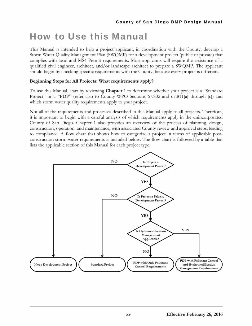
How to Use this Manual This Manual is intended to help a project applicant, in coordination with the County, develop a Storm Water Quality Management Plan (SWQMP) for a development project (public or private) that complies with local and MS4 Permit requirements. Most applicants will require the assistance of a qualified civil engineer, architect, and/or landscape architect to prepare a SWQMP. The applicant should begin by checking specific requirements with the County, because every project is different.
Beginning Steps for All Projects: What requirements apply?
To use this Manual, start by reviewing Chapter 1 to determine whether your project is a “Standard Project” or a “PDP” (refer also to County WPO Sections 67.802 and 67.811[a] through [c]) and which storm water quality requirements apply to your project.
Not all of the requirements and processes described in this Manual apply to all projects. Therefore, it is important to begin with a careful analysis of which requirements apply in the unincorporated County of San Diego. Chapter 1 also provides an overview of the process of planning, design, construction, operation, and maintenance, with associated County review and approval steps, leading to compliance. A flow chart that shows how to categorize a project in terms of applicable post-construction storm water requirements is included below. The flow chart is followed by a table that lists the applicable section of this Manual for each project type.

County of San Diego BMP Design Manual
xvi Effective February 26, 2016
Project Type
Applicable Requirements
Sour
ce C
ontr
ol a
nd
Site
Des
ign
(Cha
pter
4)
Stor
m W
ater
Pol
luta
nt
Con
trol
BM
Ps
(Cha
pter
5)
Hyd
rom
odifi
catio
n M
anag
emen
t BM
Ps
(Cha
pter
6)
Not a Development Project (without impact to storm water quality or quantity – e.g. interior remodels, routine maintenance; Refer to Section 1.3)
Requirements in this Manual do not apply
Standard Projects X
PDPs with only Pollutant Control Requirements X X
PDPs with Pollutant Control and Hydromodification Management Requirements X X X
Once an applicant has determined which requirements apply, Chapter 2 describes the specific performance standards associated with each requirement. For example, an applicant may learn from Chapter 1 that the project must meet storm water pollutant control requirements. Chapter 2 describes what these requirements entail. This chapter also provides background on key storm water concepts to help understand why these requirements are in place and how they can be met. Refer to the list of acronyms and glossary as guidance to understanding the meaning of key terms within the context of this Manual.
Next Steps for All Projects: How should an applicant approach a project storm water management design?
Most projects will then proceed to Chapter 3 to follow the step-by-step guidance to prepare a storm water project submittal for the site. This chapter does not specify any regulatory criteria beyond those already described in Chapters 1 and 2 – rather it is intended to serve as a resource for project applicants to help navigate the task of developing a compliant storm water project submittal. Note that the first steps in Chapter 3 apply to both Standard Projects and PDPs; while other steps in Chapter 3 only apply to PDPs.
The use of a step-by-step approach is highly recommended because it helps ensure that the right information is collected, analyzed, and incorporated in to project plans and submittals at the appropriate time in the County review process. It also helps facilitate a common framework for discussion between the applicant and the reviewer. However, each project is different and it may be appropriate to use a different approach as long as the applicant demonstrates compliance with the MS4 Permit requirements that apply to the project.
County of San Diego BMP Design Manual
xvii Effective February 26, 2016
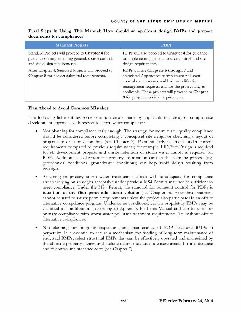
Final Steps in Using This Manual: How should an applicant design BMPs and prepare documents for compliance?
Standard Projects PDPs
Standard Projects will proceed to Chapter 4 for guidance on implementing general, source control, and site design requirements. After Chapter 4, Standard Projects will proceed to Chapter 8 for project submittal requirements.
PDPs will also proceed to Chapter 4 for guidance on implementing general, source control, and site design requirements. PDPs will use Chapters 5 through 7 and associated Appendices to implement pollutant control requirements, and hydromodification management requirements for the project site, as applicable. These projects will proceed to Chapter 8 for project submittal requirements.
Plan Ahead to Avoid Common Mistakes
The following list identifies some common errors made by applicants that delay or compromise development approvals with respect to storm water compliance.
• Not planning for compliance early enough. The strategy for storm water quality compliance should be considered before completing a conceptual site design or sketching a layout of project site or subdivision lots (see Chapter 3). Planning early is crucial under current requirements compared to previous requirements; for example, LID/Site Design is required for all development projects and onsite retention of storm water runoff is required for PDPs. Additionally, collection of necessary information early in the planning process (e.g. geotechnical conditions, groundwater conditions) can help avoid delays resulting from redesign.
• Assuming proprietary storm water treatment facilities will be adequate for compliance and/or relying on strategies acceptable under previous MS4 Permits may not be sufficient to meet compliance. Under the MS4 Permit, the standard for pollutant control for PDPs is retention of the 85th percentile storm volume (see Chapter 5). Flow-thru treatment cannot be used to satisfy permit requirements unless the project also participates in an offsite alternative compliance program. Under some conditions, certain proprietary BMPs may be classified as “biofiltration” according to Appendix F of this Manual and can be used for primary compliance with storm water pollutant treatment requirements (i.e. without offsite alternative compliance).
• Not planning for on-going inspections and maintenance of PDP structural BMPs in perpetuity. It is essential to secure a mechanism for funding of long term maintenance of structural BMPs, select structural BMPs that can be effectively operated and maintained by the ultimate property owner, and include design measures to ensure access for maintenance and to control maintenance costs (see Chapter 7).

County of San Diego BMP Design Manual
xviii Effective February 26, 2016
This page was intentionally left blank.

C O U N T Y O F S A N D I E G O B M P D E S I G N M A N U A L
1-1 Effective February 26, 2016
Chapter
1 Policies and Procedural Requirements This chapter introduces storm water management policies and is intended to help categorize a project and determine the applicable storm water management requirements as well as options for compliance. This chapter also introduces the procedural requirements for preparation, review, and approval of project submittals.
1.1 Introduction to Storm Water Management Policies
MS4 Permit Provision E.3.a-c; E.3.d.(1)
Storm water management requirements for development projects are derived from the MS4 Permit and implemented by local jurisdictions.
On May 8, 2013, the California Regional Water Quality Control Board San Diego Region (referred to as “San Diego Water Board”) reissued a municipal storm water permit titled “National Pollutant Discharge Elimination System Permit and Waste Discharge Requirements for Discharges from the MS4s draining the watersheds within the San Diego Region” (Order No. R9-2013-0001; referred to as MS4 Permit) to the municipal Copermittees. The MS4 Permit was amended in February 2015 by Order R9-2015-0001, and again in November 2015 by Order R9-2015-0100. The MS4 Permit was issued by the San Diego Water Board pursuant to section 402 of the Federal Clean Water Act and implementing regulations (Code of Federal Regulations Title 40, Part 122) adopted by the United States Environmental Protection Agency (USEPA), and Chapter 5.5, Division 7 of the California Water Code. The MS4 Permit requires each Copermittee, including the County of San Diego (County), to use its land use and planning authority to implement a development planning program to control and reduce the discharge of pollutants in storm water from new development and significant redevelopment.
Different requirements apply to different project types.
The MS4 Permit requires all development projects to implement practices that will minimize the generation of pollutants. While all development projects are required to implement source control and site design/LID practices, the MS4 Permit has additional requirements for development projects that exceed size thresholds and/or fit under specific use or location categories. These projects, referred to as PDPs, are required to incorporate structural BMPs into the project plan to reduce the discharge of pollutants, and address potential hydromodification impacts from changes in

Chapter 1: Policies and Procedural Requirements
1-2 Effective February 26, 2016
flow and sediment supply.
1.2 Purpose and Use of the Manual This Manual presents a “unified BMP design approach.”
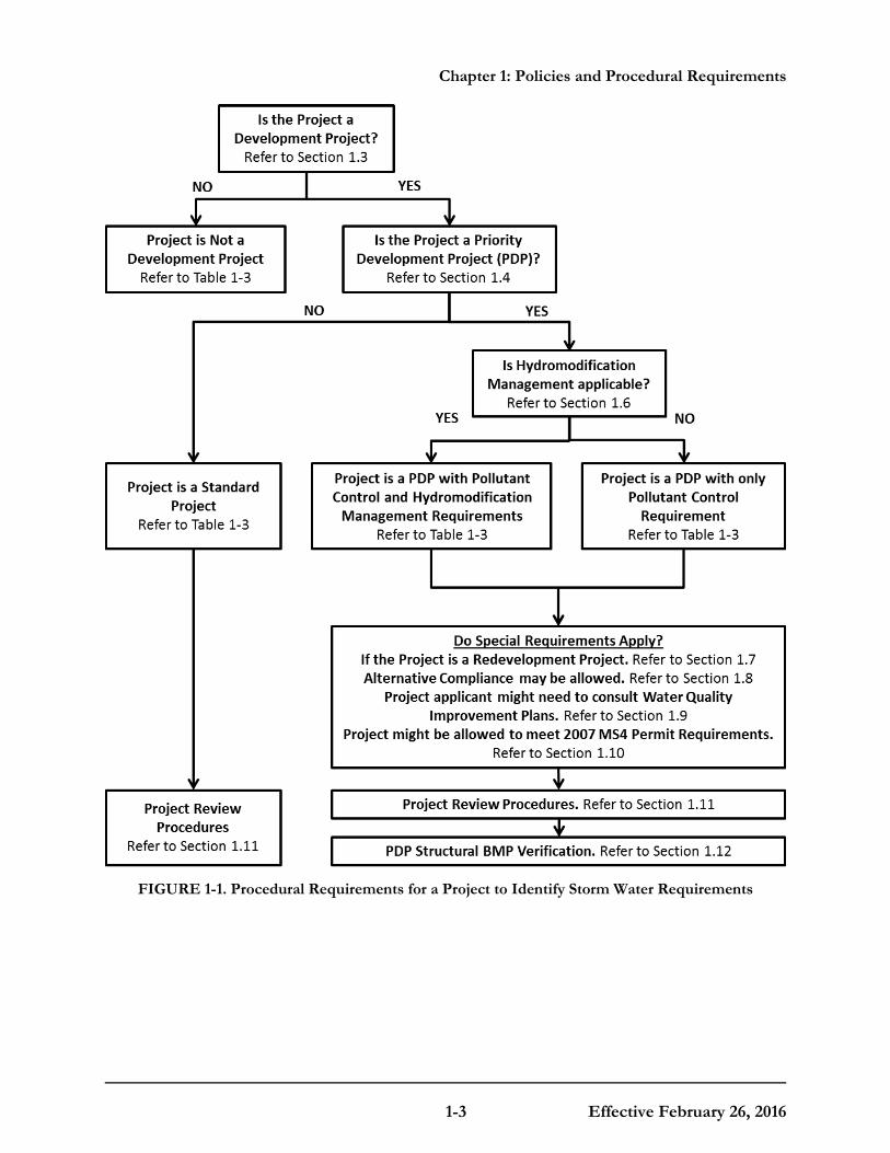
To assist the land development community, streamline project reviews, and maximize cost-effective environmental benefits, the regional Copermittees have developed a unified BMP design approach1 that meets the performance standards specified in the MS4 Permit. By following the process outlined in this Manual, project applicants (for both private and public developments) can develop a single integrated design that complies with the complex and overlapping MS4 Permit source control and site design requirements, storm water pollutant control requirements (i.e. water quality), and hydromodification management (flow-control and sediment supply) requirements. Figure 1-1 below presents a flow chart of the decision process that the Manual user should use to:
1. Categorize a project;
2. Determine storm water requirements; and
3. Understand how to submit projects for review and verification.
This figure also indicates where specific procedural steps associated with this process are addressed in Chapter 1.
Alternative BMP design approaches that meet applicable performance standards may also be acceptable.
Applicants may choose not to use the unified BMP design approach present in this Manual, in which case they will need to demonstrate to the satisfaction of the County, in their submittal, compliance with applicable performance standards. These performance standards are described in Chapter 2 and in Section E.3.c of the MS4 Permit.
1 The term “unified BMP design approach” refers to the standardized process for site and watershed investigation,
BMP selection, BMP sizing, and BMP design that is outlined and described in this manual with associated appendices and templates. This approach is considered to be “unified” because it represents a pathway for compliance with the MS4 Permit requirements that is anticipated to be reasonably consistent across the local jurisdictions in San Diego County.
Chapter 1: Policies and Procedural Requirements
1-3 Effective February 26, 2016
FIGURE 1-1. Procedural Requirements for a Project to Identify Storm Water Requirements

Chapter 1: Policies and Procedural Requirements
1-4 Effective February 26, 2016
1.2.1 Determining Applicability of Permanent BMP Requirements
The following Table 1-1 reiterates the procedural requirements indicated in Figure 1-1 in a step-wise checklist format. The purpose of Table 1-1 is to guide applicants to appropriate sections in Chapter 1 to identify the post-construction storm water requirements applicable for a project. Table 1-1 is not intended to be used as a project intake form. Applicability checklist of permanent, post-construction storm water BMP requirements is available in the County Intake Form in Appendix A.

Chapter 1: Policies and Procedural Requirements
1-5 Effective February 26, 2016
TABLE 1-1. Checklist for a Project to Identify Applicable Post-Construction Storm Water Requirements
Step 1. Is the project a Development Project? Yes No See Section 1.3 for guidance. A phase of a project can also be categorized as a development project. If “Yes” then continue to Step 2. If “No” then stop here; Permanent BMP requirements do not apply i.e. requirements in this Manual are not applicable to the project.
Step 2. Is the project a PDP? Is the project located West of the Pacific /Salton Sea Divide?
PDP requirements in this Manual only pertain to projects in the areas west of the Pacific/Salton Divide (Region 9 of the Water Quality Control Board). See Map at http://www.waterboards.ca.gov/waterboards_map.shtml. If “Yes” then continue to Step 2b. If “No” then stop here: Standard Project requirements apply (and for projects subject to the Construction General Permit, Post-Construction Standards of the Construction General Permit apply east of the Pacific / Salton Sea Divide)..
Yes No
Step 2b. Does the project fit one of the PDP definitions a-f? See Section 1.4.1 for guidance. If “Yes” then continue to Step 2c. If “No” then stop here; only Standard Project requirements apply.
Yes No
Step 2c. Does the project qualify for requiring meeting 2007 MS4 Permit requirements? See Section 1.10 for guidance. If “Yes” then continue to Step 2d. If “No” then go to Step 2e.
Yes No
Step 2d. Does the project fit one of the PDP definitions in the 2007 MS4 Permit? See SDRWQCB Order No. R9-2007-0001, Provision D.1.d. If “Yes” then continue to Step 2e. If “No” then stop here; Standard Project requirements apply.
Yes No
Step 2e. Do one of the exceptions to PDP definitions in this Manual apply to the project? See Section 1.4.3 for guidance. If “Yes” then stop here; Standard Project requirements apply, along with additional requirements that qualify the project for the exception. If “No” then continue to Step 3; the project is a PDP.
Yes No
Step 3. Is the Project Subject to Earlier PDP Requirements Due to a Prior Lawful Approval?
Yes No
See Section 1.10 for guidance. If “Yes” then you may follow the structural BMP requirements, including any hydromodification management exemptions, found in the earlier version of the County SUSMP manual. If “No” then continue to Step 4.
Step 4. Do Hydromodification Control Requirements Apply? Yes No See Section 1.6 for guidance. If “Yes” then continue to Step 4a. If “No” then stop here; PDP with only pollutant control requirements, apply to the project.
Chapter 1: Policies and Procedural Requirements
1-6 Effective February 26, 2016
1.3 Defining a Project Not all site improvements are considered “development projects” under the Region 9 MS4 Permit.
This Manual is intended for new development and redevelopment projects, inclusive of both private- and public funded projects. Development projects are defined by the MS4 Permit as "construction, rehabilitation, redevelopment, or reconstruction of any public or private projects". Development projects are issued County permits to allow construction activities. To further clarify, this Manual applies only to development or redevelopment activities that have the potential to contact storm water and contribute an anthropogenic source of pollutants, or reduce the natural absorption and infiltration abilities of the land.
A project must be defined consistent with the California Environmental Quality Act (CEQA) definitions of "project."
CEQA defines a project as: a discretionary action being undertaken by a public agency that would have a direct or reasonably foreseeable indirect impact on the physical environment. This includes actions by the agency, financing and grants, and permits, licenses, plans, regulations or other entitlements granted by the agency. CEQA requires that the project include “the whole of the action” before the agency. This requirement precludes "piecemealing," which is the improper (and often artificial) separation of a project into smaller parts in order to avoid preparing EIR-level documentation.
In the context of this Manual, the "project" is the "whole of the action" which has the potential for adding or replacing or resulting in the addition or replacement of, roofs, pavement, or other impervious surfaces and thereby resulting in increased flows and storm water pollutants. "Whole of the action" means the project may not be segmented or phased into small parts either onsite or offsite if the effect is to reduce the quantity of impervious area and fall below thresholds for applicability of storm water requirements.
When defining the project, the following questions are considered: • What are the project activities? • Do they occur onsite or offsite? • What are the limits of the project (project boundary)? • What is the whole of the action associated with the project (i.e. what is the total amount of
new or replaced impervious area considering all of the collective project components through all phases of the project)?
• Are any facilities or agreements to build facilities offsite in conjunction with providing service to the project (street widening, utilities)?
The following discretionary County permits and approvals are considered projects:
(A) Administrative permit for clearing, including modification, minor deviation, or extension. (B) Administrative permit for small recycling collection facility, including modification, minor
deviation, or extension. (C) Certificate of compliance. (D) Final map modification.

Chapter 1: Policies and Procedural Requirements
1-7 Effective February 26, 2016
(E) Grading plans or grading permits, if approval is discretionary, including modification or renewal.
(F) Improvement Plan, including modification. (G) Landscape Plan. (H) Major Use Permit, including modification, minor deviation, or extension. (I) Minor Use Permit, including modification, minor deviation, or extension. (J) Parcel map modification.
(K) Reclamation plan. (L) Site plan, including modification, minor deviation, or extension.
(M) Solid waste facility permit. (N) Tentative map, including resolution amendment, time extension, expired tentative map and
revised tentative map. (O) Tentative parcel map, including resolution amendment, time extension, expired tentative
parcel map and revised tentative parcel map. (P) Watercourse permit. (Q) Farm Employee Housing (R) Guest Living Quarters (S) Horse Stable (T) Host Home (U) MET Facilities (V) Mobile Financial Business Office (W) Oversized Structures (X) Photovoltaic Solar Energy System Offsite Use (Y) Recycling Collection Facility – Small (Z) Second Dwelling Unit/Garage
(AA) Small Winery (BB) Wind Turbine – Small
The following ministerial permits are considered projects:
(A) Building permit. (B) Construction right of way permit (C) Encroachment permit. (D) Excavation permit. (E) Grading plans or grading permits, if approval is ministerial, including modification or
renewal. (F) On-site wastewater system permit. (G) Underground tank permit. (H) Well permit.
Neither of these lists is exhaustive. Other permit types may be projects.
Table 1-2 is used to determine whether storm water management requirements defined in the MS4 Permit and presented in this Manual apply to the project.
If a project meets one of the exemptions in Table 1-2 then permanent BMP requirements do not apply to the project, i.e. requirements in this Manual are not applicable. If permanent BMP

Chapter 1: Policies and Procedural Requirements
1-8 Effective February 26, 2016
requirements apply to a project, Sections 1.4 to 1.7 will further define the extent of the applicable requirements based on the MS4 Permit. The MS4 Permit and WPO Sections 67.811(a) and (b) contain standard requirements that are applicable to all projects (Standard Projects and PDPs), and more specific requirements for projects that are classified as PDPs.
TABLE 1-2. Applicability of Permanent, Post-Construction Storm Water Requirements
Do permanent storm water requirements apply to your project?
Requirements DO NOT apply to:
Replacement of impervious surfaces that are part of a routine maintenance activity, such as:
• Replacing roof material on an existing building
• Rebuilding a structure to original design after damage from earthquake, fire or similar disasters
• Restoring pavement or other surface materials affected by trenches from utility work
• Resurfacing existing roads and parking lots, including slurry, overlay and restriping
• Routine replacement of damaged pavement, including full depth replacement, if the sole purpose is to repair the damaged pavement
• Resurfacing existing sidewalks, pedestrian ramps or bike lanes on existing roads (within existing street right-of-way)
• Restoring a historic building to its original historic design Note: Work that creates impervious surface outside of the existing impervious footprint is not considered routine maintenance. Repair or improvements to an existing building or structure that do not alter the size:
• Plumbing, electrical and HVAC work
• Interior alterations including major interior remodels and tenant build-out within an existing commercial building
• Exterior alterations that do not change the general dimensions and structural framing of the building (does not include building additions or projects where the existing building is demolished)

Chapter 1: Policies and Procedural Requirements
1-9 Effective February 26, 2016
1.3.1 Determine Applicability of Construction BMP Requirements
MS4 Permit Provision E.1.a
All construction activities, whether or not they are deemed to be development projects are required to ensure no pollutants are discharged to the MS4. Applicable construction site BMPs are required to be implemented (WPO Section 67.809). All development projects, or phases of development projects, even if exempted from meeting some or all of the Permanent BMP Requirements, are required to implement temporary erosion, sediment, good housekeeping and pollution prevention BMPs to mitigate storm water pollutants during the construction phase. For detailed information on these requirements see the following sources:
• Statewide Construction General Permit (Order No. 2009-0009-DWQ);
• MS4 permit Section E.4., Construction Management; and
• WPO Section 67.809, Additional Requirements for Construction Projects, of the Watershed Protection Ordinance.
County Stormwater Quality Management Plans (SWQMPs) must address construction BMP requirements even when a SWPPP is not required.
1.4 Is the Project a PDP? MS4 Permit Provision E.3.b.(1)
PDP categories are defined by the MS4 Permit, but the PDP categories can be expanded by the County, and the County can offer specific exemptions from PDP categories.
Section 1.4.1 presents the PDP categories defined in the MS4 Permit. Section 1.4.2 presents additional PDP categories and/or expanded PDP definitions that apply to the County. Section 1.4.3 presents specific County exemptions.
Projects that do not meet the priority project criteria are considered Standard projects. As such, these projects need only to complete a Standard SWQMP unless the County requires a PDP SWQMP for the project. All projects east of the Pacific/Salton Sea Divide should complete a Standard SWQMP. In addition, the following types of projects/permits typically address water quality via a Standard SWQMP.
• Construction Right of Way Permits; • Encroachment Permits; • Minor Excavation Permits; • Variances; • Boundary Adjustments; • Minor Use Permits for Cellular Facilities, and;
• Residential Tentative Parcel Maps Building Permits..

Chapter 1: Policies and Procedural Requirements
1-10 Effective February 26, 2016
1.4.1 PDP Categories
In the MS4 Permit, PDP categories are defined based on project size, type and design features.
Projects must be classified as PDPs if they are in one or more of the PDP categories presented in the MS4 Permit, which are listed below. Review each category, defined in (a) through (f), below. A PDP applicability checklist for these categories is also provided in the Intake Form within Appendix A. If any of the categories match the project, the entire project is a PDP. For example, if a project feature such as a parking lot falls into a PDP category, then the entire development footprint including project components that otherwise would not have been designated a PDP on their own (such as other impervious components that did not meet PDP size thresholds, and/or landscaped areas), must be subject to PDP requirements. Note that size thresholds for impervious surface created or replaced vary based on land use, land characteristics, and whether the project is a new development or redevelopment project. Therefore, all definitions must be reviewed carefully. Also, note that categories are defined by the total quantity of “added or replaced” impervious surface, not the net change in impervious surface.
For example, consider a redevelopment project that adds 7,500 square feet of new impervious surface and removes 4,000 square feet of existing impervious surface. The project has a net increase of 3,500 square feet of impervious surface. However, the project is still classified as a PDP because the total added or replaced impervious surface is 7,500 square feet, which is greater than 5,000 square feet.
"Collectively" for the purposes of the Manual means that all contiguous and non-contiguous parts of the project that represent the whole of the action must be summed up. For example, consider a residential development project that will include the following impervious components:
• 3,600 square feet of roadway • 350 square feet of sidewalk • 4,800 square feet of roofs • 1,200 square feet of driveways • 500 square feet of walkways/porches
The collective impervious area is 10,450 square feet.
PDP Categories defined by the MS4 Permit: 2 (a) New development projects that create 10,000 square feet or more of impervious surfaces3
(collectively over the entire project site). This includes commercial, industrial, residential, mixed-use, and public development projects on public or private land.
(b) Redevelopment projects that create and/or replace 5,000 square feet or more of impervious
2 In interpreting the applicability of these categories, applicants should note that any development project that will create
and/or replace 10,000 square feet or more of impervious surface (collectively over the entire project site) is considered a new development. See the definition of New Development in Appendix M.
3 For solar energy farm projects, the area of the solar panels does not count toward the total impervious area of the site.

Chapter 1: Policies and Procedural Requirements
1-11 Effective February 26, 2016
surface (collectively over the entire project site on an existing site of 10,000 square feet or more of impervious surfaces). This includes commercial, industrial, residential, mixed-use, and public development projects on public or private land.
(c) New and redevelopment projects that create and/or replace 5,000 square feet or more of impervious surface (collectively over the entire project site), and support one or more of the following uses:
(i) Restaurants. This category is defined as a facility that sells prepared foods and drinks for consumption, including stationary lunch counters and refreshment stands selling prepared foods and drinks for immediate consumption (Standard Industrial Classification (SIC) code 5812). Information and an SIC search function are available at https://www.osha.gov/pls/imis/sicsearch.html.
(ii) Hillside development projects. This category includes development on any natural slope that is twenty-five percent or greater.
(iii) Parking lots. This category is defined as a land area or facility for the temporary parking or storage of motor vehicles used personally, for business, or for commerce.
(iv) Streets, roads, highways, freeways, and driveways. This category is defined as any paved impervious surface used for the transportation of automobiles, trucks, motorcycles, and other vehicles.
(d) New or redevelopment projects that create and/or replace 2,500 square feet or more of impervious surface (collectively over the entire project site), and discharging directly to an Environmentally Sensitive Area (ESA). “Discharging directly to” includes flow that is conveyed overland a distance of 200 feet or less from the project to the ESA, or conveyed in a pipe or open channel any distance as an isolated flow from the project to the ESA (i.e. not commingled with flows from adjacent lands).
Note: ESAs are areas that include but are not limited to all Clean Water Act Section 303(d) impaired water bodies; areas designated as Areas of Special Biological Significance by the State Water Board and San Diego Water Board; State Water Quality Protected Areas; water bodies designated with the RARE beneficial use by the State Water Board and San Diego Water Board; and any other equivalent environmentally sensitive areas which have been identified by the County (see Section 1.4.2 below to determine if any other local areas have been identified).
For projects adjacent to an ESA, but not discharging to an ESA, the 2,500 square foot threshold does not apply as long as the project does not physically disturb the ESA and the ESA is upstream of the project.
(e) New development projects, or redevelopment projects that create and/or replace 5,000 square feet or more of impervious surface, that support one or more of the following uses:
(i) Automotive repair shops. This category is defined as a facility that is categorized in any one of the following SIC codes: 5013, 5014, 5541, 7532-7534, or 7536-7539. Information and an SIC search function are available at https://www.osha.gov/pls/imis/sicsearch.html.
(ii) Retail gasoline outlets. This category includes Retail gasoline outlets that meet the following criteria: (a) 5,000 square feet or more or (b) a projected Average Daily Traffic of 100 or more vehicles per day.

Chapter 1: Policies and Procedural Requirements
1-12 Effective February 26, 2016
(f) New or redevelopment projects that result in the disturbance of one or more acres of land and are expected to generate pollutants post construction.
Exclusions that apply to this category only: Projects creating less than 5,000 square feet of impervious surface and where any added landscaping does not require regular use of pesticides and fertilizers, such as a slope stabilization project using native plants, are excluded from this category. Calculation of the square footage of impervious surface need not include linear pathways that are for infrequent vehicle use, such as for emergency or maintenance access or for bicycle or pedestrian use, if they are built with pervious surfaces or if they sheet flow to surrounding pervious surfaces. See Section 1.4.2 for additional guidance.
Area that may be excluded from impervious area calculations for determining if the project is a PDP:
(a) Consistent with Table 1-2, areas of a project that are considered exempt from storm water requirements (e.g. routine maintenance activities, resurfacing, etc.) should not be included as part of “added or replaced” impervious surface in determining project classification.
(b) Swimming pools and decorative ponds with adequate freeboard or an overflow structure that does not release overflow to the MS4.
Redevelopment projects may have special considerations with regards to the total area required to be treated. Refer to Section 1.7.
1.4.2 Local Additional PDP Categories and/or Expanded PDP Definitions
PDP Category (d) of the MS4 Permit as described above (Section 1.4.1) is dependent upon what is considered an ESA. The County defines ESAs as the areas described above in Section 1.4.1 (RARE, 303(d), and ASBS), and also the following areas are identified as ESAs:
• Multiple Species Conservation Program (MSCP) Preserved Lands • MSCP Hardline Preserve • Open Space Conservation Element (General Plan)
Mapped ESAs in GIS, including all of the identified elements above, can be found in the SanGIS/ SANDAG GIS Data Warehouse (online at http://www.sangis.org/download/index.html).
PDP category (f) of the MS4 Permit, as described in Section 1.4.1, requires jurisdictions to define land uses or activities that are expected to generate pollutants post-construction, but that do not meet other categorical PDP definitions. The County has not categorically identified additional PDP types, but may do so on a case-by-case basis during the project application process.
1.4.3 Local PDP Exemptions or Alternative PDP Requirements
The MS4 Permit requires that more specific runoff treatment controls and hydromodification controls be incorporated into Priority Development Projects. These requirements only pertain to projects in the areas west of the Pacific/Salton Sea Divide. Projects located east of the Pacific/Salton Sea Divide are not considered priority development projects.
As allowed by MS4 Permit Section E.3.b.(3) and WPO Section 67.811(b)(2), the County may exempt

Chapter 1: Policies and Procedural Requirements
1-13 Effective February 26, 2016
certain projects from being defined as PDPs, or to apply alternative PDP requirements as follows:
(A) New or retrofit paved sidewalks, bicycle lanes, or trails that meet the following criteria:
i. Designed and constructed to direct storm water runoff to adjacent vegetated areas, or other non-erodible permeable areas; OR
ii. Designed and constructed to be hydraulically disconnected from paved streets or roads [i.e., runoff from the new improvement does not drain directly onto paved streets or roads]; OR
iii. Designed and constructed with permeable pavements or surfaces in accordance with USEPA Green Streets Guidance (USEPA, 2008).
(B) Retrofitting or redevelopment of existing paved alleys, streets or roads that are designed and constructed in accordance with the USEPA Green Streets Guidance (USEPA, 2008)
Guidance for items (A)iii and (B) is provided in Appendix K (Guidance on Green Infrastructure).
Projects may be exempt from PDP requirements only if they are comprised solely of one of the project types listed within the category. For example, even though sidewalks, trails, or frontage roads might exist within a larger PDP footprint, this would not qualify the PDP to utilize the exemption. Likewise, an exemption cannot be claimed by dividing a PDP into smaller projects and then applying the exemption to one of them, e.g., separating out a frontage road from a PDP and then applying the exemption to the frontage road only.
Appendix K (Guidance on Green Infrastructure) provides guidance for implementing green street and other green infrastructure project features and types. Regardless of whether a project qualifies to utilize either of the exemption types above, applicants are encouraged to utilize Appendix K as a basis for designing and constructing low impact design and sustainable infrastructure features for their projects.
An exemption or alternative to PDP requirements based on the above criteria may, at the County’s discretion, modify the requirements for structural pollutant control and hydromodification control BMPs described in Chapters 5 and 6 of this Manual, and annual verification of long term operation and maintenance described in Chapter 7 of this Manual. However, projects meeting the above criteria for exemption or alternative requirements are still minimally subject to source control and site design requirements presented in Chapter 4. See also Chapter 2, Table 2-1 for a description of requirements and performance standards applicable to different project scenarios.

Chapter 1: Policies and Procedural Requirements
1-14 Effective February 26, 2016
1.5 Determining Applicable Storm Water Management Requirements
MS4 Permit Provision E.3.c.(1)
Depending on project type and receiving water, different storm water management requirements apply.
New development or redevelopment projects that are not classified as PDPs or that are PDP exempt, based on Section 1.4, are called "Standard Projects." Source control and site design requirements apply to all projects including Standard Projects and PDPs. Additional structural BMP requirements (i.e. pollutant control and hydromodification management) apply generally to all PDPs, except for those that have been specifically exempted from hydromodification management requirements per WPO Section 67.811(b)(5)(B). Also note that projects that consist solely of redeveloping or retrofitting existing paved alleys, streets, and roads are exempted from PDP status under WPO Section 67.811(b)(2)(B). These projects must comply with the structural pollutant control, but not the hydromodification management, requirements of the MS4 Permit. The applicability of different storm water management requirements by project type, including references to applicable sections of this Manual, is summarized in Table 1-3.

Chapter 1: Policies and Procedural Requirements
1-15 Effective February 26, 2016
TABLE 1-3. Applicability of Manual Sections for Different Project Types
Project Type
Project Development
Process (Chapter 3
and 8)
Source Control and Site Design
(Section 2.1 and Chapter
4)
Structural Pollutant Control
(Section 2.2 and Chapter 5 and
7)
Structural Hydromodification
Management
(Section 2.3, 2.4 and Chapter 6 and 7)
Not a Development Project The requirements of this Manual do not apply
Standard Projects
Standard Project based on PDP classification criteria (Section 1.4) NA NA
PDP-exempted Projects
• New or retrofit paved sidewalks, bicycle lanes, or trails (Section 1.4.3)
NA NA
• Retrofitting or redevelopment of paved alleys, streets or roads (Section 1.4.3)
NA
PDPs
• PDPs without HMP Exemptions (Section 1.4)
• PDPs with HMP Exemption (Sections 1.6 and 6.1) NA
1.6 Applicability of Hydromodification Management Requirements
MS4 Permit Provision E.3.c.(2)
Hydromodification management requirements apply to PDPs only.
If the project is a Standard Project, hydromodification management requirements do not apply. Hydromodification management requirements apply to PDPs (both new and re-development) unless the project meets specific exemptions discussed below.
PDP exemptions from hydromodification management requirements are based on the
Chapter 1: Policies and Procedural Requirements
1-16 Effective February 26, 2016
receiving water system.
The County has the discretion to exempt a PDP from hydromodification management requirements where the project discharges storm water runoff to:
(i) Existing underground storm drains discharging directly to water storage reservoirs, lakes, enclosed embayments, or the Pacific Ocean;
(ii) Conveyance channels whose bed and bank are concrete lined all the way from the point of discharge to water storage reservoirs, lakes, enclosed embayments, or the Pacific Ocean; or
(iii) An area identified by the County as appropriate for an exemption by the optional WMAA incorporated into the Water Quality Improvement Plan (WQIP) pursuant to Provision B.3.b.(4) [of the MS4 permit].
Refer to Figure 1-2 and the associated criteria describing nodes in Figure 1-2 to determine applicability of hydromodification management requirements. These criteria reflect the latest list of exemptions that are allowed under the 2013 MS4 Permit, and therefore supersede criteria found in earlier publications.
• Figure 1-2, Node 1 – Hydromodification management control measures are only required if the proposed project is a PDP.
• Figure 1-2, Node 2 – As allowed by the MS4 Permit, projects discharging directly to the Pacific Ocean, by either existing underground storm drain systems or conveyance channels whose bed and bank are concrete-lined all the way from the point of discharge to the Pacific Ocean, are exempt.
o This exemption is subject to the following conditions:
a) The outfall must be located on the beach (not within or on top of a bluff),
b) A properly sized energy dissipation system must be provided to mitigate outlet discharge velocity from the direct discharge to the ocean for the ultimate condition peak design flow of the direct discharge,
c) The invert elevation of the direct discharge conveyance system (at the point of discharge to the ocean) should be equal to or below the mean high tide water surface elevation at the point of discharge, unless the outfall discharges to a quay or other non-erodible shore protection.
• Figure 1-2, Node 3 – As allowed by the MS4 Permit, projects discharging directly to enclosed embayments (e.g., San Diego Bay or Mission Bay), by either existing underground storm drain systems or conveyance channels whose bed and bank are concrete-lined all the way from the point of discharge to the enclosed embayment, are exempt.
o This exemption is subject to the following conditions:
a) The outfall must not be located within a wildlife refuge or reserve area (e.g., Kendall-Frost Mission Bay Marsh Reserve, San Diego Bay National Wildlife Refuge, San Diego National Wildlife Refuge),
b) A properly sized energy dissipation system must be provided to mitigate outlet discharge velocity from the direct discharge to the enclosed embayment for the ultimate condition peak design flow of the direct discharge,

Chapter 1: Policies and Procedural Requirements
1-17 Effective February 26, 2016
c) The invert elevation of the direct discharge conveyance system (at the point of discharge to the enclosed embayment) should be equal to or below the mean high tide water surface elevation at the point of discharge, unless the outfall discharges to a quay or other non-erodible shore protection.
• Figure 1-2, Node 4 – As allowed by the MS4 Permit, projects discharging directly to a water storage reservoir or lake, by either existing underground storm drain systems or conveyance channels whose bed and bank are concrete-lined all the way from the point of discharge to the water storage reservoir or lake, are exempt.
o This exemption is subject to the following conditions:
a) A properly sized energy dissipation system must be provided in accordance with County design standards to mitigate outlet discharge velocity from the direct discharge to the water storage reservoir or lake for the ultimate condition peak design flow of the direct discharge,
b) The invert elevation of the direct discharge conveyance system (at the point of discharge to the water storage reservoir or lake) should be equal to or below the lowest normal operating water surface elevation at the point of discharge, unless the outfall discharges to quay or other non-erodible shore protection. Normal operating water surface elevation may vary by season; contact the reservoir operator to determine the elevation. For cases in which the direct discharge conveyance system outlet invert elevation is above the lowest normal operating water surface elevation but below the reservoir spillway elevation, additional analysis is required to determine if energy dissipation should be extended between the conveyance system outlet and the elevation associated with the lowest normal operating water surface level.
c) No exemption may be granted for conveyance system outlet invert elevations located above the reservoir spillway elevation.
• Figure 1-2, Node 5 – As allowed by the MS4 Permit, projects discharging directly to an area identified as appropriate for an exemption in the WMAA for the watershed in which the project resides, by either existing underground storm drain systems or conveyance channels whose bed and bank are concrete-lined all the way from the point of discharge to the designated area, are exempt. Consult the WMAA within the WQIP for the watershed in which the project resides to determine areas identified as appropriate for an exemption. Exemption is subject to any criteria defined within the WMAA, and conditions described in this Manual.
o To qualify as a direct discharge to an exempt river reach:
a) A properly sized energy dissipation system must be provided to mitigate outlet discharge velocity from the direct discharge to the exempt river reach for the ultimate condition peak design flow of the direct discharge,
b) The invert elevation of the direct discharge conveyance system (at the point of discharge to the exempt river reach) should be equal to or below the 10-year floodplain elevation. To qualify for this exemption, projects must discharge runoff such that the outlet is located and the discharge occurs within the limits of inundation of the river due to the occurrence of the peak flow of the 10-year flooding event. Exceptions may be made at the discretion of the County, but may never exceed the 100-year floodplain elevation. The County may require additional
Chapter 1: Policies and Procedural Requirements
1-18 Effective February 26, 2016
analysis of the potential for erosion between the outfall and the 10-year floodplain elevation.
c) No exemption may be granted for conveyance system outlet invert elevations located above the 100-year floodplain elevation.

Chapter 1: Policies and Procedural Requirements
1-19 Effective February 26, 2016
*Direct discharge refers to an uninterrupted hardened conveyance system; Note to be used in conjunction with Node Descriptions.
FIGURE 1-2. Applicability of Hydromodification Management BMP Requirements
1. Is the project a PDP? YES
Exempt from hydromodification management requirements
Hydromodification management controls required
2. Direct discharge to Pacific Ocean?
3. Direct discharge to enclosed embayment, not within protected
area?
4. Direct discharge to water storage reservoir or lake, below spillway or normal operating
level?
5. Direct discharge to an area identified in WMAA?
NOYES
YES
YES
YES
NO
NO
NO
NO

Chapter 1: Policies and Procedural Requirements
1-20 Effective February 26, 2016
1.7 Special Considerations for Redevelopment Projects (50% Rule)
MS4 Permit Provision E.3.b.(2)
Redevelopment PDPs (PDPs on previously developed sites) may need to meet storm water management requirements for ALL impervious areas (collectively) within the ENTIRE project site.
Per MS4 Permit Section E.3.b.(2) and WPO Section 67.811(b)(3), if the project is a redevelopment project, the structural BMP performance requirements and hydromodification management requirements apply to redevelopment PDPs as follows:
(a) Where redevelopment results in the creation or replacement of impervious surface in an amount of less than fifty percent of the surface area of the previously existing development, then the structural BMP performance requirements of MS4 Permit Provision E.3.c and WPO Section 67.811(b)(4) and (5) apply only to the creation or replacement of impervious surface, and not the entire development; or
(b) Where redevelopment results in the creation or replacement of impervious surface in an amount of more than fifty percent of the surface area of the previously existing development, then the structural BMP performance requirements of MS4 Permit Provision E.3.c and WPO Section 67.811(b)(4) and (5) apply to the entire development.
These requirements for managing storm water on an entire redevelopment project site are commonly referred to as the "50% rule". For the purpose of calculating the ratio, the surface area of the previously existing development is the area of impervious surface within the previously existing development. The following steps should be followed to estimate the area that requires treatment to satisfy the MS4 Permit requirements:
1. How much total impervious area currently exists on the site?
2. How much existing impervious area will be replaced with new impervious area?
3. How much new impervious area will be created in areas that are pervious in the existing condition?
4. Total created and/or replaced impervious surface = Step 2 + Step 3.
5. 50% rule test: Is step 4 more than 50% of Step 1? If yes, treat all impervious surface on the site. If no, then treat only Step 4 impervious surface and any area that comingles with created and/or replaced impervious surface area.
Note: Steps 2 and Step 3 must not overlap as it is fundamentally not possible for a given area to be both “replaced” and “created” at the same time. Also activities that occur as routine maintenance may not be included in Step 2 and Step 3 calculation.
For example, a 10,000 square feet development proposes replacement of 4,000 square feet of impervious area. The treated area is less than 50% of the total development area and only the 4,000 square feet area is required to be treated.
Chapter 1: Policies and Procedural Requirements
1-21 Effective February 26, 2016
1.8 Offsite Alternative Compliance Program MS4 Permit Provision E.3.c.(1).(b); E.3.c.(2).(c); E.3.c.(3)
PDPs may be allowed to participate in an offsite alternative compliance program.
Per MS4 Permit Provision E.3.c.(1), the County may use its discretion to develop an offsite alternative compliance program for the unincorporated County. This allows PDPs within the county jurisdiction and a defined watershed area to partially or wholly satisfy the PDP structural BMP performance requirements for retention and/or biofiltration or hydromodification through offsite projects that achieve a “greater overall water quality benefit”. Participation in an offsite alternative compliance program would allow a PDP to fulfill the requirement of providing retention and/or biofiltration pollutant controls onsite that completely fulfill the performance standards specified in Chapter 5 (pollutant controls) with onsite flow-thru treatment controls and offsite mitigation of the DCV not retained onsite. It would also potentially relieve hydromodification management flow control obligations that are not provided onsite (see Chapter 6 for hydromodification management requirements). PDPs must consult the County for specific guidelines and requirements for participation in potential offsite alternative compliance programs.
Figure 1-3 generally represents two potential pathways for participating in offsite alternative compliance (i.e. offsite projects that supplement the PDPs onsite BMP obligations).
• The first pathway (illustrated using solid line, left side) ultimately ends at offsite alternative compliance if the PDP cannot meet all of the onsite pollutant control obligations via retention and/or biofiltration. This pathway requires performing feasibility analysis for retention and biofiltration BMPs prior to participation in an offsite alternative compliance project.
• The second pathway (illustrated using dashed line, right side) is a discretionary pathway along which the County may allow for PDPs to proceed directly to an offsite alternative compliance project without demonstrating infeasibility of retention and/or biofiltration BMPs onsite.
Per WPO Section 67.811(b)(6), a PDP may be allowed at the County’s discretion to utilize offsite alternative compliance in lieu of complying with the storm water pollutant control and hydromodification BMP performance requirements in WPO Section 67.811(b)(4)-(5). For any such approvals, the following apply:
• The PDP must mitigate for the portion of the pollutant load in the design capture volume not retained onsite and/or post-project runoff conditions not fully managed onsite consistent with a Water Quality Equivalency (WQE) Guidance Document accepted by the RWQCB.
• If a PDP is allowed to utilize offsite alternative compliance, flow-thru treatment control BMPs must be implemented to treat the portion of the design capture volume that is not reliably retained onsite.
• Flow-thru treatment control BMPs must be sized and designed in accordance with the requirements of Section 67.811(b)(4)(C).
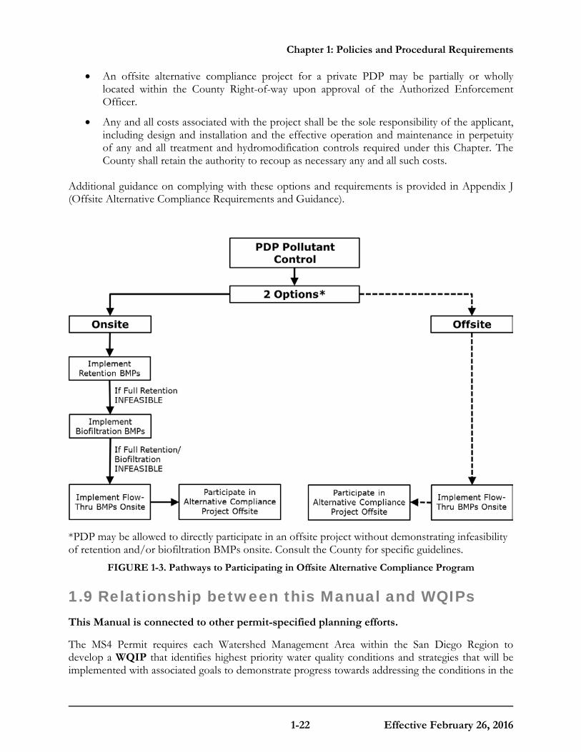
Chapter 1: Policies and Procedural Requirements
1-22 Effective February 26, 2016
• An offsite alternative compliance project for a private PDP may be partially or wholly located within the County Right-of-way upon approval of the Authorized Enforcement Officer.
• Any and all costs associated with the project shall be the sole responsibility of the applicant, including design and installation and the effective operation and maintenance in perpetuity of any and all treatment and hydromodification controls required under this Chapter. The County shall retain the authority to recoup as necessary any and all such costs.
Additional guidance on complying with these options and requirements is provided in Appendix J (Offsite Alternative Compliance Requirements and Guidance).
*PDP may be allowed to directly participate in an offsite project without demonstrating infeasibility of retention and/or biofiltration BMPs onsite. Consult the County for specific guidelines.
FIGURE 1-3. Pathways to Participating in Offsite Alternative Compliance Program
1.9 Relationship between this Manual and WQIPs This Manual is connected to other permit-specified planning efforts.
The MS4 Permit requires each Watershed Management Area within the San Diego Region to develop a WQIP that identifies highest priority water quality conditions and strategies that will be implemented with associated goals to demonstrate progress towards addressing the conditions in the

Chapter 1: Policies and Procedural Requirements
1-23 Effective February 26, 2016
watershed. The MS4 Permit also provides an option to perform a WMAA as part of the WQIP to develop watershed specific requirements for structural BMP implementation in the watershed management area. PDPs should expect to consult either of these separate planning documents as appropriate when using this Manual as follows:
1. For PDPs that implement flow-thru treatment BMPs, selection of the type of BMP must consider the pollutants and conditions of concerns. Among the selection considerations, the applicant must consult the highest priority water quality condition as identified in the WQIP for that particular watershed management area.
2. There may be watershed management area-specific BMPs or strategies that are identified in WQIPs, for which PDPs should consult and incorporate as appropriate.
3. As part of the hydromodification management obligations that PDPs must comply with, applicants must avoid and allow bypass of critical coarse sediment yield areas through application of the methodology presented in Section 6.2 and Appendix H of this guidance.
4. PDPs may be exempt from implementing hydromodification management BMPs (Chapter 6) based on the exemptions indicated in Section 1.6, and potentially from additional exemptions recommended in the WMAA attachment to the WQIPs. Applicants should consult the WMAA for recommended hydromodification management exemptions to determine if the project is eligible.
5. PDP applicants may have the option of participating in an offsite alternative compliance program. Refer to Section 1.8 and Appendix J.
These relationships between this Manual and WQIPs are presented in Figure 1-4.
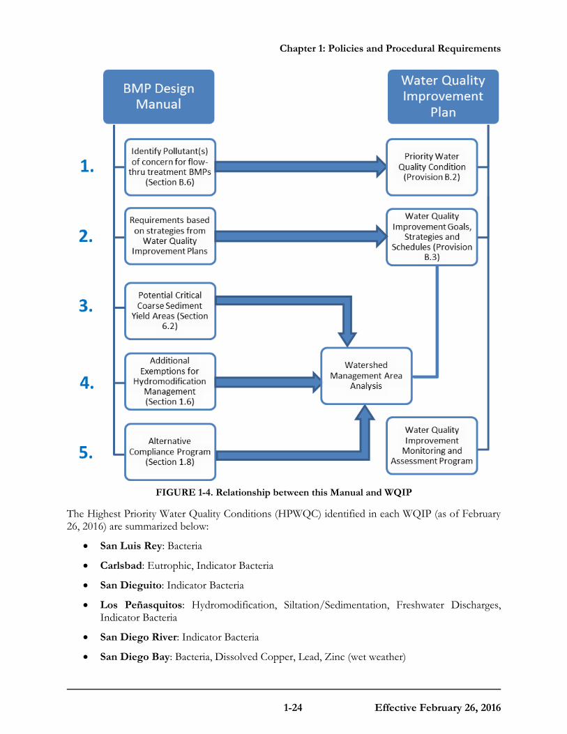
Chapter 1: Policies and Procedural Requirements
1-24 Effective February 26, 2016
FIGURE 1-4. Relationship between this Manual and WQIP
The Highest Priority Water Quality Conditions (HPWQC) identified in each WQIP (as of February 26, 2016) are summarized below:
• San Luis Rey: Bacteria
• Carlsbad: Eutrophic, Indicator Bacteria
• San Dieguito: Indicator Bacteria
• Los Peñasquitos: Hydromodification, Siltation/Sedimentation, Freshwater Discharges, Indicator Bacteria
• San Diego River: Indicator Bacteria
• San Diego Bay: Bacteria, Dissolved Copper, Lead, Zinc (wet weather)
Chapter 1: Policies and Procedural Requirements
1-25 Effective February 26, 2016
• Tijuana: Sedimentation/Siltation (wet weather), Turbidity (wet weather)
All of the WQIPs and WMAAs that apply to the unincorporated areas of the County can be found at the Project Clean Water website, http://www.projectcleanwater.org/index.php. Applicants should refer to the applicable document for each individual watershed. Please refer to these documents, which may be periodically updated, to ensure the most up-to-date HPWQCs are considered.
1.10 Storm Water Requirement Applicability Timeline MS4 Permit Provision E.3.e.(1)(a)
Prior Lawful Approval (PLA)
Per MS4 Permit Section E.3.e.(1) and WPO Section 67.811(c), the requirements of this Manual apply to all development projects unless a prior lawful approval (PLA) to proceed under the provisions of a prior MS4 Permit has been obtained from the County. The Authorized Enforcement Official may partially or wholly waive these requirements for any private or public development project meeting all of the conditions described either under Option 1 or 2 below. As it determines necessary, the County may deny a request for prior lawful approval under previous land development requirements, or impose additional conditions that are more restrictive than those requirements. Prior lawful approvals may also be restricted or revoked if a PDP fails to maintain compliance with the conditions of that approval.
Option 1: Vested Rights Option
Per WPO Section 67.811(c)(1), previous land development requirements may be allowed to apply to any portion or phase of a development project for which the Authorized Enforcement Official determines the County lacks the land use authority or legal authority to require the project to implement the requirements of WPO Sections 67.811(a) and/or (b).
Option 2: Grandfathering per MS4 Permit Section E.3.e.(1)(a)
Per WPO Section 67.811(c)(2)), the Authorized Enforcement Official may, at its discretion, allow the requirements of the immediately prior MS4 Permit to apply to any portion or phase of a Priority Development Project for which all of the conditions described in items (A) through (D) below have been satisfied prior to the effective date of the current MS4 Permit provisions.
(A) Initial Approvals. Prior to the effective date of the current MS4 Permit provisions (the effective date of the 2013 MS4 Permit provisions is February 16, 2016), the applicant must have:
i. Obtained an approval of a design that incorporates the storm water drainage system for the Priority Development Project in its entirety, including all applicable structural and hydromodification management BMPs consistent with the requirements of the prior MS4 permit. For public projects, a design stamped by the County Engineer or engineer of record for the project is considered an approved design; and
ii. Been issued a project permit or approval that authorizes the commencement of construction activities based on the design approved in (A)i above.
Chapter 1: Policies and Procedural Requirements
1-26 Effective February 26, 2016
(B) Commencement of Construction. Within 365 days prior to, or 180 days after, the effective date of the current MS4 Permit provisions, the applicant must have demonstrated to the Authorized Enforcement Official’s satisfaction that construction activities have commenced on any portion of the Priority Development Project site, where the construction activities are undertaken in reliance on the permit or approval obtained per item (A)(ii) above.
(C) Subsequent Approvals. Within five years of the effective date of the current MS4 Permit provisions, the applicant must have obtained all subsequent project permits or approvals that are needed to implement the design initially approved in conformance with WPO Section 67.811(c)(2)(A)i. After that time, any portion or phase of a Priority Development Project for which subsequent approvals have not been obtained is required to meet the updated requirements of WPO Section 67.811(a) and (b).
(D) Substantial Conformance. The storm water drainage system for the Priority Development Project in its entirety, including all applicable structural pollutant treatment control and hydromodification management BMPs must remain in substantial conformity with the design initially approved in conformance with WPO Section 67.811(c)(2)(A)i. Any portion or phase of a Priority Development Project not maintaining substantial conformity with this design is required to meet the updated requirements of WPO Sections 67.811(a) and (b).
Additional information and guidance on complying with PLA provisions are provided in Appendix L (Prior Lawful Approval Requirements and Guidance).
1.11 Project Review Procedures The County reviews project plans for compliance with applicable requirements of this Manual and the MS4 Permit.
The project applicant must provide sufficient documentation to demonstrate that applicable requirements of the MS4 Permit and WPO will be met.
For Standard Projects, this means using a Standard Project SWQMP to document that the following general requirements of the MS4 Permit are met, and showing applicable features onsite grading, building, improvement, and landscaping plans:
• BMP Requirements for All Development Projects, which includes general requirements, source control BMP requirements, and narrative (i.e. not numerically-sized) site design requirements (MS4 Permit Provision E.3.a and WPO Section 67.811[a]).
For PDPs, this means preparing a PDP SWQMP to document that the following general requirements of MS4 Permit Provisions E.3.a through c and WPO Sections 67.811(a) and (b) are met, and showing applicable features on grading and landscaping plans:
• BMP Requirements for All Development Projects, which includes general requirements for siting of permanent, post-construction BMPs, source control BMP requirements, and narrative (i.e. not numerically-sized) site design requirements;
• Storm Water Pollutant Control BMP Requirements, for numerically sized onsite structural BMPs to control pollutants in storm water; and
• Hydromodification Management BMP Requirements, which includes protection of critical sediment yield areas and numerically sized onsite BMPs to manage hydromodification that may be caused by storm water runoff discharged from a project.

Chapter 1: Policies and Procedural Requirements
1-27 Effective February 26, 2016
Detailed submittal requirements are provided in Chapter 8 of this Manual.
1.12 PDP Structural BMP Verification MS4 Permit Provision E.3.e.(1)
Structural BMPs must be verified by the County prior to project occupancy.
Pursuant to MS4 Permit Provision E.3.e.(1), each Copermittee must require and confirm the following with respect to PDPs constructed within their jurisdiction:
(a) Each Copermittee must require and confirm that appropriate easements and ownerships are properly recorded in public records and the information is conveyed to all appropriate parties when there is a change in project or site ownership.
(b) Each Copermittee must require and confirm that prior to occupancy and/or intended use of any portion of the PDP, each structural BMP is inspected to verify that it has been constructed and is operating in compliance with all of its specifications, plans, permits, ordinances, and the requirements of the MS4 Permit.
For PDPs, this means that after structural BMPs have been constructed, the County will require the project applicant or owner to provide a verification that the site improvements for the project have been constructed in conformance with the approved storm water management documents and drawings.
The County encourages inspection of structural BMPs at each significant construction stage and at completion. Following construction, the County may require an addendum to the PDP SWQMP and require as-builts to address any changes to the structural BMPs that occurred during construction that were approved by the County. The County may also require a final update to the Maintenance Plan, and/or execution of a maintenance agreement that will be recorded for the property. A maintenance agreement that is recorded with the property title can then be transferred to future owners.
Verification of structural BMPs, updates to reports, and recordation of a maintenance agreement may occur concurrently with project closeout, but could be required sooner. In all cases, MS4 Permit Provision E.3.e.(1) and WPO Section 67.811(b)(8) require verification prior to occupancy and/or intended use of the project. Specific procedures are provided in Chapter 8 of this Manual.

Chapter 1: Policies and Procedural Requirements
1-28 Effective February 26, 2016
This page was intentionally left blank.

C O U N T Y O F S A N D I E G O B M P D E S I G N M A N U A L
2-1 Effective February 26, 2016
Chapter
2 Performance Standards and Concepts Projects must meet three separate performance standards, as applicable.
The MS4 Permit establishes separate performance standards for (1) source control and site design practices, (2) storm water pollutant control BMPs, and (3) hydromodification management BMPs. Chapter 1 provided guidance for determining which performance standards apply to a given project. This chapter defines these performance standards based on the MS4 Permit, and presents concepts that provide the project applicant with technical background, explains why the performance standards are important, and gives a general description of how these performance standards can be met. Table 2-1 also summarizes the applicability of these standards for different project types. Detailed procedures for meeting the performance standards are presented in Chapters 4, 5, and 6.
Performance standards can be met through an integrated approach.
While three separate performance standards are defined by this Manual, an overlapping set of design features can be used as part of demonstrating conformance to each standard. Further discussion of the relationship between performance standards is provided in Section 2.4.

Chapter 2: Performance Standards and Concepts
2-2 Effective February 26, 2016
TABLE 2-1. Applicability of Performance Standards for Different Project Types
Project Type
Source Control and Site Design
(Section 2.1 and Chapter
4)
Structural Pollutant Control
(Section 2.2 and Chapter 5 and 7)
Structural Hydromodification
Management
(Section 2.3, 2.4 and Chapter 6 and 7)
Standard Projects
Standard Projects based on PDP classification criteria (Section 1.4) NA NA
PDP-exempted Projects
• New or retrofit paved sidewalks, bicycle lanes, or trails (Section 1.4.3)
NA NA
• Retrofitting or redevelopment of paved alleys, streets or roads (Section 1.4.3)
NA
PDPs
• PDPs without HMP Exemptions (Section 1.4)
• PDPs with HMP Exemptions (Section 6.1)
NA
2.1 Source Control and Site Design Requirements for All Development Projects
2.1.1 Performance Standards
MS4 Permit Provision E.3.a
MS4 Permit Provision E.3.a and WPO Section 67.811(a) define performance standards for general, source control, and site design practices that are applicable to all projects (regardless of project type or size; both Standard Projects and PDPs) when County permits are issued.
2.1.1.1 General Requirements
All projects must meet the following general requirements:
Chapter 2: Performance Standards and Concepts
2-3 Effective February 26, 2016
(a) Onsite BMPs must be located so as to remove pollutants from runoff prior to its discharge to any receiving waters, and as close to the source as possible;
(b) Structural BMPs must not be constructed within waters of the United States (U.S.); and
(c) Onsite BMPs must be designed and implemented with measures to avoid the creation of nuisance or pollution associated with vectors (e.g. mosquitos, rodents, or flies).
2.1.1.2 Source Control Requirements Pollutant source control BMPs are features that must be implemented to address specific sources of pollutants.
The following source control BMPs must be implemented at all development projects where applicable and technically feasible:
(a) Prevention of illicit discharges into the MS4;
(b) Storm drain system stenciling or signage;
(c) Protection of outdoor material storage areas from rainfall, run-on, runoff, and wind dispersal;
(d) Protection of materials stored in outdoor work areas from rainfall, run-on, runoff, and wind dispersal;
(e) Protection of trash storage areas from rainfall, run-on, runoff, and wind dispersal; and
(f) Use of any additional BMPs determined to be necessary by the County to minimize pollutant generation at each project.
Further guidance is provided in Section 2.1.2 and Chapter 4.
2.1.1.3 Site Design Requirements
Site design requirements are qualitative requirements that apply to the layout and design of ALL development project sites (Standard Projects and PDPs).
Site design performance standards define minimum requirements for how a site must incorporate LID BMPs, including the location of BMPs and the use of integrated site design practices. The following site design practices must be implemented at all development projects, where applicable and technically feasible:
(a) Maintenance or restoration of natural storage reservoirs and drainage corridors (including topographic depressions, areas of permeable soils, natural swales, and ephemeral and intermittent streams)4;
(b) Buffer zones for natural water bodies (where buffer zones are technically infeasible, require project applicant to include other buffers such as trees, access restrictions, etc.);
(c) Conservation of natural areas within the project footprint including existing trees, other
4 Development projects proposing to dredge or fill materials in waters of the U.S. must obtain a Clean Water Act
Section 401 Water Quality Certification. Projects proposing to dredge or fill waters of the state must obtain waste discharge requirements.
Chapter 2: Performance Standards and Concepts
2-4 Effective February 26, 2016
vegetation, and soils;
(d) Construction of streets, sidewalks, or parking lot aisles to the minimum widths necessary, provided public safety is not compromised;
(e) Minimization of the impervious footprint of the project;
(f) Minimization of soil compaction to landscaped areas;
(g) Disconnection of impervious surfaces through distributed pervious areas;
(h) Landscaped or other pervious areas designed and constructed to effectively receive and infiltrate, retain and/or treat runoff from impervious areas, prior to discharging to the MS4;
(i) Small collection strategies located at, or as close as possible to, the source (i.e. the point where storm water initially meets the ground) to minimize the transport of runoff and pollutants to the MS4 and receiving waters;
(j) Use of permeable materials for projects with low traffic areas and appropriate soil conditions;
(k) Landscaping with native or drought tolerant species; and
(l) Harvesting and using precipitation.
A key aspect of this performance standard is that these design features must be used where applicable and feasible. Responsible implementation of this performance standard depends on evaluating applicability and feasibility. Further guidance is provided in Section 2.1.2 and Chapter 4.
Additional site design requirements may apply to PDPs.
Site design decisions may influence the ability of a PDP to meet applicable performance standards for pollutant control and hydromodification management BMPs (as defined in Section 2.2 and 2.3). For example, the layout of the site drainage and reservation of areas for BMPs relative to areas of infiltrative soils may influence the feasibility of capturing and managing storm water to meet storm water pollutant control and/or hydromodification management requirements. As such, the County may require additional site design practices, beyond those listed above, to be considered and documented as part of demonstrating conformance to storm water pollutant control and hydromodification management requirements.
Appendix K (Guidance for Green Infrastructure Projects) provides guidance for implementing green street and other green infrastructure project features and types. Applicants are encouraged to utilize Appendix K as a basis for designing and constructing low impact design and sustainable infrastructure features for their projects.
2.1.2 Concepts and References
Land development tends to increase the amount of pollutants in storm water runoff.
Land development generally alters the natural conditions of the land by removing vegetative cover, compacting soil, and/or placement of concrete, asphalt, or other impervious surfaces. These impervious surfaces facilitate entrainment of urban pollutants in storm water runoff (such as pesticides, petroleum hydrocarbons, heavy metals, and pathogens) that are otherwise not generally found in high concentrations in the runoff from the natural environment. Pollutants that accumulate

Chapter 2: Performance Standards and Concepts
2-5 Effective February 26, 2016
on impervious surfaces and actively landscaped pervious surfaces may contribute to elevated levels of pollutants in runoff relative to the natural condition.
Land development also impacts site hydrology.
Impervious surfaces greatly affect the natural hydrology of the land because they do not allow natural infiltration, retention, evapotranspiration and treatment of storm water runoff to take place. Instead, storm water runoff from impervious surfaces is typically and has traditionally been directed through pipes, curbs, gutters, and other hardscape into receiving waters, with little treatment, at significantly increased volumes and accelerated flow rates over what would occur naturally. The increased pollutant loads, storm water volume, discharge rates and velocities, and discharge durations from the MS4 adversely impact stream habitat by causing accelerated, unnatural erosion and scouring within creek beds and banks. Compaction of pervious areas can have a similar effect to impervious surfaces on natural hydrology.
Site Design LID involves attempting to maintain or restore the predevelopment hydrologic regime.
LID is a comprehensive land planning and engineering design approach with a goal of maintaining and enhancing the pre-development hydrologic regime of urban and developing watersheds. LID designs seeks to control storm water at the source, using small-scale integrated site design and management practices to mimic the natural hydrology of a site, retain storm water runoff by minimizing soil compaction and impervious surfaces, and disconnecting storm water runoff from conveyances to the storm drain system. Site Design LID BMPs may utilize interception, storage, evaporation, evapotranspiration, infiltration, and filtration processes to retain and/or treat pollutants in storm water before it is discharged from a site. Examples of Site Design LID BMPs include using permeable pavements, rain gardens, rain barrels, grassy swales, soil amendments, and native plants.
Site design must be considered early in the design process.
Site designs tend to be more flexible in the early stages of project planning than later on when plans become more detailed. Because of the importance of the location of BMPs, site design should be considered as early as the planning/tentative design stage. Site design is critical for feasibility of storm water pollutant control BMPs (Section 2.2) as well as coarse sediment supply considerations associated with hydromodification management (introduced in Section 2.3).
Source control and site design (LID) requirements help avoid impacts by controlling pollutant sources and changes in hydrology.
Source control and site design practices prescribed by the MS4 Permit are the minimum management practices, control techniques and system, design and engineering methods to be included in the planning procedures to reduce the discharge of pollutants from development projects, regardless of size or purpose of the development. In contrast to storm water pollutant control BMPs and hydromodification control BMPs which are intended to mitigate impacts, source control and site design BMPs are intended to avoid or minimize these impacts by managing site hydrology, providing treatment features integrated within the site, and reducing or preventing the introduction of pollutants from specific sources. Implementation of site design BMPs will result in reduction in storm water runoff generated by the site. Methods to estimate effective runoff coefficients and the storm water runoff produced by the site after site design BMPs are implemented are` presented in Appendix B.2. This methodology is applicable for PDPs that are required to

Chapter 2: Performance Standards and Concepts
2-6 Effective February 26, 2016
estimate runoff produced from the site with site design BMPs implemented so that they can appropriately size storm water pollutant control BMPs and hydromodification control BMPs.
The location of BMPs matters.
The site design BMPs listed in the performance standard include practices that either prevent runoff from occurring or manage runoff as close to the source as possible. This helps create a more hydrologically effective site and reduces the requirements that pollutant control and hydromodification control BMPs must meet, where required. Additionally, because sites may have spatially-variable conditions, the locations reserved for structural BMPs within the site can influence whether these BMPs can feasibly retain, treat, and/or detain storm water to comply with structural pollutant control and hydromodification control requirements, where applicable. Finally, the performance standard specifies that onsite BMPs must remove pollutants from runoff prior to discharge to any receiving waters or the MS4, be located/constructed as close to the pollutant generating source as possible and must not be constructed within waters of the U.S.
The selection of BMPs also matters.
The lists of source control and site design BMPs specified in the performance standard must be used “where applicable and feasible.” This is an important concept – BMPs should be selected to meet the R9-2013-0001 permit requirements and are feasible with consideration of site conditions and project type. By using BMPs that are applicable and feasible, the project can achieve benefits of these practices, while not incurring unnecessary expenses (associated with using practices that do not apply or would not be effective) or creating undesirable conditions (for example, infiltration-related issues, vector concerns including mosquito breeding, etc.).
Methods to select and design BMPs and demonstrate compliance with source control and site design requirements are presented in Chapter 4 of this Manual. Source control and site design fact sheets are also provided in Appendix E.
2.2 Storm Water Pollutant Control Requirements for PDPs
2.2.1 Storm Water Pollutant Control Performance Standard
MS4 Permit Provision E.3.c.(1)
Per MS4 Permit Provision E.3.c.(1) and WPO Section 67.811(b)(4)(A)-(C), Storm Water Pollutant Control BMPs for PDPs must meet the following performance standards:
(a) Each PDP shall implement BMPs that are designed to retain (i.e. intercept, store, infiltrate, evaporate, and evapotranspire) onsite the pollutants contained in the volume of storm water runoff produced from a 24-hour, 85th percentile storm event (Design Capture Volume (DCV)). The 24-hour, 85th percentile storm event shall be based on Figure B.1-1 in Appendix B or an approved site-specific rainfall analysis.
(i) If it is not technically feasible to implement retention BMPs for the full DCV onsite for a PDP, then the PDP shall utilize biofiltration BMPs for the remaining volume not reliably retained. Biofiltration BMPs must be designed as described in Appendix F to
Chapter 2: Performance Standards and Concepts
2-7 Effective February 26, 2016
have an appropriate hydraulic loading rate to maximize storm water retention and pollutant removal, as well as to prevent erosion, scour, and channeling within the BMP, and must be sized to:
[a]. Treat 1.5 times the DCV not reliably retained onsite, OR
[b]. Treat the DCV not reliably retained onsite with a flow-thru design that has a total volume, including pore spaces and pre-filter detention volume, sized to hold at least 0.75 times the portion of the DCV not reliably retained onsite.
(ii) If biofiltration BMPs are not technically feasible, then the PDP shall utilize flow-thru treatment control BMPs (selected and designed per Appendix B.6) to treat runoff leaving the site, AND participate in offsite alternative compliance to mitigate for the pollutants from the DCV not reliably retained onsite pursuant to Section 2.2.1.(b). Flow-thru treatment control BMPs must be sized and designed to:
[a]. Remove pollutants from storm water to the MEP (defined by the MS4 Permit) by following the guidance in Appendix B.6; and
[b]. Filter or treat either: 1) the maximum flow rate of runoff produced from a rainfall intensity of 0.2 inch of rainfall per hour, for each hour of a storm event, or 2) the maximum flow rate of runoff produced by the 85th percentile hourly rainfall intensity (for each hour of a storm event), as determined from the local historical rainfall record, multiplied by a factor of two (both methods may be adjusted for the portion of the DCV retained onsite as described in Appendix B.6) and
[c]. Meet the flow-thru treatment control BMP treatment performance standard described in Appendix B.6.
(b) A PDP may be allowed to participate in an offsite alternative compliance program in lieu of fully complying with the performance standards for storm water pollutant control BMPs onsite, see Section 1.8 and Appendix J. When an offsite alternative compliance program is utilized:
(i) The PDP must mitigate for the portion of the DCV not reliably retained onsite and
(ii) Flow-thru treatment control BMPs must be implemented to treat the portion of the DCV that is not reliably retained onsite. Flow-thru treatment control BMPs must be selected and sized in accordance with Appendix B.6.
(iii) A PDP may be allowed to propose an offsite alternative compliance project not identified in the WMAA of the WQIP if the requirements in Section 1.8 and Appendix J are met at the discretion of the County.
Demonstrations of feasibility findings and calculations to justify BMP selection and design must be provided by the project applicant in the SWQMP to the satisfaction of the County. Methodology to demonstrate compliance with the performance standards, described above, applicable to storm water pollutant control BMPs for PDPs is detailed in Chapter 5.
2.2.2 Concepts and References
Retention BMPs are the most effective type of BMPs to reduce pollutants discharging to MS4s when they are sited and designed appropriately.
Chapter 2: Performance Standards and Concepts
2-8 Effective February 26, 2016
Retention of the required DCV will achieve 100 percent pollutant removal efficiency (i.e. prevent pollutants from discharging directly to the MS4). Thus, retention of as much storm water onsite as technically feasible is the most effective way to reduce pollutants in storm water discharges to, and consequently from the MS4, and remove pollutants in storm water discharges from a site to the MEP.
However, in order to accrue these benefits, retention BMPs must be technically feasible and suitable for the project. Retention BMPs that fail prematurely, under-perform, or result in unintended consequences as a result of improper selection or siting may achieve performance that is inferior to other BMP types while posing other issues for property owners and the County. Therefore, this manual provides criteria for evaluating feasibility and provides options for other types of BMPs to be used if retention is not technically feasible.
Biofiltration BMPs can be sized to achieve approximately the same pollutant removal as retention BMPs.
In the case, where the entire DCV cannot be retained onsite because it is not technically feasible, PDPs are required to use biofiltration BMPs with specific sizing and design criteria listed in Appendix B.5 and Appendix F. These sizing and design criteria are intended to provide a level of long term pollutant removal that is reasonably equivalent to retention of the DCV.
Flow-thru treatment BMPs are required to treat the pollutant loads in the DCV not retained or biofiltered onsite to the MEP.
If the pollutant loads from the full DCV cannot feasibly be retained or biofiltered onsite, then PDPs are required to implement flow-thru treatment control BMPs to remove the pollutants to the MEP for the portion of the DCV that could not be feasibly retained or biofiltered. Flow-thru treatment BMPs may only be implemented to address onsite storm water pollutant control requirements if coupled with an offsite alternative compliance project that mitigates for the portion of the pollutant load in the DCV not retained or biofiltered onsite.
Offsite Alternative Compliance Program may be available.
The MS4 Permit allows the County the discretion to grant PDPs permission to utilize an offsite alternative compliance program for meeting the pollutant control performance standard. Onsite and offsite mitigation is required when a PDP is allowed to use an offsite alternative compliance program. The specific parameters of an offsite alternative compliance program will be specific to each jurisdiction if one is available (Refer to Section 1.8 and Appendix J).
Methods to design and demonstrate compliance with storm water pollutant control BMPs are presented in Chapter 5 of this Manual. Definitions and concepts that should be understood when sizing storm water pollutant control BMPs to be in compliance with the performance standards are explained below:
2.2.2.1 Best Management Practices
To minimize confusion, this Manual considers all references to “facilities,” “features,” or “controls” to be incorporated into development projects as BMPs.
Chapter 2: Performance Standards and Concepts
2-9 Effective February 26, 2016
2.2.2.2 DCV
The MS4 Permit requires pollutants be addressed for the runoff from the 24-hour 85th percentile storm event (“DCV”) as the design standard to which PDPs must comply.
The 85th percentile, 24-hour storm event is the event that has a precipitation total greater than or equal to 85 percent of all storm events over a given period of record in a specific area or location. For example, to determine what the 85th percentile storm event is in a specific location, the following steps would be followed:
• Obtain representative precipitation data, preferably no less than 30-years period if possible.
• Divide the recorded precipitation into 24-hour precipitation totals.
• Filter out events with no measurable precipitation (less than 0.01 inches of precipitation).
• Of the remaining events, calculate the 85th percentile value (i.e. 15 percent of the storms would be greater than the number determined to be the 85th percentile, 24-hour storm).
The 85th percentile, 24-hour storm event depth is then used in hydrologic calculations to calculate the DCV for sizing storm water pollutant control BMPs. An exhibit showing the 85th percentile, 24-hour storm depth across San Diego County and the methodology used to develop this exhibit is included in Appendix B.1.3. Guidance to estimate the DCV is presented in Appendix B.1.
2.2.2.3 Implementation of Storm Water Pollutant Control BMPs
The MS4 Permit requires that the PDP applicants proposing to meet the performance standards onsite implement storm water pollutant control BMPs in the order listed below. That is, the PDP applicant first needs to implement all feasible onsite retention BMPs needed to meet the storm water pollutant control BMP requirements prior to installing onsite biofiltration BMPs, and then onsite biofiltration BMPs prior to installing onsite flow-thru treatment control BMPs.
PDP applicants may be allowed to participate in an offsite alternative compliance program. Refer to Section 1.8 for additional guidance.
Retention BMPs: Structural measures that provide retention (i.e. intercept, store, infiltrate, evaporate and evapotranspire) of storm water as part of pollutant control strategy. Examples include infiltration BMPs and cisterns, bioretention BMPs and biofiltration with partial retention BMPs.
Biofiltration BMPs: Structural measures that provide biofiltration of storm water as part of the pollutant control strategy.
Flow-thru treatment control BMPs: Structural measures that provide flow-thru treatment as part of the pollutant control strategy. Examples include vegetated swales and media filters.
For example, if the DCV from a site is 10,000 cubic feet (ft3) and it is technically feasible to implement 2,000 ft3 of retention BMPs and 9,000 ft3 of biofiltration BMPs sized using Section 2.2.1.(a)(i)[a], and the County has an offsite alternative compliance program to satisfy the requirements of this Manual, the project applicant should:
1) First, design retention BMPs for 2,000 ft3.
2) Then complete a technical feasibility form for retention BMPs (included in Appendix C and
Chapter 2: Performance Standards and Concepts
2-10 Effective February 26, 2016
D) demonstrating that it’s only technically feasible to implement retention BMPs for 2,000 ft3.
3) Then design biofiltration BMPs for 9,000 ft3 (calculate equivalent volume for which the pollutants are retained = 9,000/1.5 = 6,000 ft3).
4) Then complete a technical feasibility for biofiltration BMPs demonstrating that it is only technically feasible to implement biofiltration BMPS for 9,000 ft3.
5) Estimate the DCV that could not be retained or biofiltered = 10,000 ft3 – (2,000 ft3 + 6,000 ft3) = 2,000 ft3.
6) Implement flow-thru treatment control BMPs to treat the pollutants in the remaining 2,000 ft3. Refer to Appendix B.6 for guidance with the design of flow-thru treatment control BMPs.
7) Also participate in an offsite alternative compliance project for 2,000 ft3. Refer to Section 1.8 for additional guidance on participation in an offsite alternative compliance program.
2.2.2.4 Technical Feasibility
MS4 Permit Requirement E.3.c.(5)
Analysis of technical feasibility is necessary to select the appropriate BMPs for a site.
PDPs are required to implement pollutant control BMPs in the order of priority in Section 2.2.2.3 based on determinations of technical feasibility. In order to assist the project applicant in selecting BMPs, this Manual includes a defined process for evaluating feasibility. Conceptually, the feasibility criteria contained in this Manual are intended to:
• Promote reliable and effective long term operations of BMPs by providing a BMP selection process that eliminates the use of BMPs that are not suitable for site conditions, project type or other factors;
• Minimize significant risks to property, human health, and/or environmental degradation (e.g. geotechnical stability, groundwater quality) as a result of selection of BMPs that are undesirable for a given site; and
• Describe circumstances under which regional and watershed-based strategies, as part of an approved WMAA and an offsite alternative compliance program developed by the jurisdiction where the project resides, may be selected.
Steps for performing technical feasibility analyses are described in detail in Chapter 5. More specific guidance related to geotechnical investigation guidelines for feasibility of storm water infiltration and groundwater quality and water balance factors is provided in Appendices C and D, respectively.
2.2.2.5 Biofiltration BMPs
The MS4 Permit requires Biofiltration BMPs be designed to have an appropriate hydraulic loading rate to maximize storm water retention and pollutant removal, as well as to prevent erosion, scour, and channeling within the BMP. Appendix F of this Manual has guidance for hydraulic loading rates and other biofiltration design criteria to meet these required goals. Appendix F also has a checklist that will need to be completed by the project SWQMP preparer during plan submittal. Guidance for

Chapter 2: Performance Standards and Concepts
2-11 Effective February 26, 2016
sizing Biofiltration BMPs is included in Chapter 5 and Appendices B.5 and F.
2.2.2.6 Flow-thru Treatment Control BMPs (for use with Offsite Alternative Compliance)
MS4 Permit Requirement E.3.d.2-3
The MS4 Permit requires that the flow-thru treatment control BMP selected by the PDP applicant be ranked with high or medium pollutant removal efficiency for the most significant pollutant of concern. Steps to select the flow-thru treatment control BMP include:
• Step 1: Identify the pollutant(s) of concern by considering the following at a minimum a) Receiving water quality; b) Highest priority water quality conditions identified in the Watershed Management Areas Water Quality Improvement Plan; c) Land use type of the project and pollutants associated with that land use type and d) Pollutants expected to be present onsite.
• Step 2: Identify the most significant pollutant of concern. A project could have multiple most significant pollutants of concerns and must include the highest priority water quality condition identified in the watershed WQIP and pollutants expected to be presented onsite/from land use.
• Step 3: Effectiveness of the flow-thru treatment control BMP for the identified most significant pollutant of concern.
Methodology for sizing flow-thru treatment control BMPs and the resources required to identify the pollutant(s) of concern and effectiveness of flow-thru treatment control BMPs are included in Chapter 5 and Appendix B.6.
2.3 Hydromodification Management Requirements for PDPs
2.3.1 Hydromodification Management Performance Standards
MS4 Permit Provision E.3.c.(2)
This section describes performance standards for hydromodification management, including flow control of post-project storm water runoff and protection of critical sediment yield areas, that must be met by all PDPs unless exempt from hydromodification management requirements per Section 1.6 of this Manual. Each PDP must implement onsite BMPs to manage hydromodification that may be caused by storm water runoff discharged from a project as follows:
(a) Post-project runoff conditions (flow rates and durations) must not exceed pre-development runoff conditions by more than 10 percent (for the range of flows that result in increased potential for erosion, or degraded instream habitat downstream of PDPs).
(i) In evaluating the range of flows that results in increased potential for erosion of natural (non-hardened) channels, the lower boundary must correspond with the critical channel flow that produces the critical shear stress that initiates channel bed movement or that erodes the toe of channel banks.

Chapter 2: Performance Standards and Concepts
2-12 Effective February 26, 2016
(b) Each PDP must avoid and allow bypass of critical sediment yield areas known to the County or identified by the optional WMAA pursuant to Provision B.3.b.(4) [of the MS4 Permit], or implement measures that allow critical coarse sediment to be discharged to receiving waters, such that there is no net impact to the receiving water. Refer to Section 6.2 and Appendix H for additional guidance.
(c) A PDP may be allowed to utilize offsite alternative compliance under Provision E.3.c.(3) [of the MS4 Permit] in lieu of complying with the performance requirements of Provision E.3.c.(2)(a). The PDP must mitigate for the post-project runoff conditions not fully managed onsite if Provision E.3.c.(3) is utilized. Refer to Section 1.8 and Appendix J for additional guidance.
Hydromodification management requirements apply to both new development and redevelopment PDPs, except those that are exempt based on discharging to downstream channels or water bodies that are not subject to erosion, as defined in either the MS4 Permit (Provision E.3.c.(2).(d)) or the WMAA for the watershed in which the project resides. Exemptions from hydromodification management requirements are described in Section 1.6 of this Manual.
For undisturbed sites, the existing condition should be taken to be the pre-development runoff condition. For redevelopment PDPs or sites that have been previously disturbed, pre-development runoff conditions must be approximated by applying the parameters of a pervious area rather than an impervious area to the existing site, using the existing onsite grade and assuming the infiltration characteristics of the underlying soil.
For San Diego area watersheds, the range of flows that result in increased potential for erosion or degraded instream habitat downstream of PDPs and the critical channel flow must be based on the "Final Hydromodification Management Plan Prepared for County of San Diego, California March 2011" (herein, "March 2011 Final HMP"). For PDPs subject to hydromodification management requirements, the range of flows to control depends on the erosion susceptibility of the receiving stream and must be:
• 0.1Q2 to Q10 for streams with high susceptibility to erosion (this is the default range of flows to control when a stream susceptibility study has not been prepared);
• 0.3Q2 to Q10 for streams with medium susceptibility to erosion and which has a stream susceptibility study prepared and approved by the County; or
• 0.5Q2 to Q10 for streams with low susceptibility to erosion and which has a stream susceptibility study prepared and approved by the County.
Tools for assessing stream susceptibility to erosion have been developed by Southern California Coastal Water Research Project (SCCWRP). The tools are presented in the March 2011 Final HMP and also available through SCCWRP's website. If a PDP applicant intends to select the 0.3Q2 or 0.5Q2 threshold, the SCCWRP screening tool must be completed and submitted with other project documentation.
The March 2011 Final HMP does not provide criteria for protection of critical sediment yield areas. The standard as presented in the MS4 Permit and shown above is: avoid and allow bypass of critical sediment yield areas or implement measures that allow critical coarse sediment to be discharged to receiving waters, such that there is no net impact to the receiving water.
Chapter 2: Performance Standards and Concepts
2-13 Effective February 26, 2016
Methods to demonstrate compliance with hydromodification management requirements, including protection of critical coarse sediment yield areas and flow control for post-project runoff from the project site, are presented in Chapter 6 of this Manual. Hydromodification management concepts, theories, and references are described below.
2.3.2 Hydromodification Management Concepts and References
2.3.2.1 What is Hydromodification?
The MS4 Permit defines hydromodification as the change in the natural watershed hydrologic processes and runoff characteristics (i.e. interception, infiltration, overland flow, and groundwater flow) caused by urbanization or other land use changes that result in increased stream flows and sediment transport. In addition, alteration of stream and river channels, such as stream channelization, concrete lining, installation of dams and water impoundments, and excessive streambank and shoreline erosion are also considered hydromodification, due to their disruption of natural watershed hydrologic processes.
Typical impacts to natural watershed hydrologic processes and runoff characteristics resulting from new development and redevelopment include:
• Decreased interception and infiltration of rainfall at the project site due to removal of native vegetation, compaction of pervious area soils, and the addition of impervious area;
• Increased connectivity and efficiency of drainage systems serving the project site, including concentration of project-site runoff to discrete outfalls;
• Increased runoff volume, flow rate, and duration from the project site due to addition of impervious area, removal of native vegetation, and compaction of pervious area soils;
• Reduction of critical coarse sediment supply from the project site to downstream natural systems (e.g. streams) due to stabilization of developed areas, stabilization of streams, and addition of basins that trap sediment (either by design as a permanent desilting basin or storm water quality treatment basin that settles sediment, or incidentally as a peak flow management basin); and
• Interruption of critical coarse sediment transport in streams due to stream crossings such as culverts or ford crossings that incidentally slow stream flow and allow coarse sediment to settle upstream of the crossing.
Any of these changes can result in increased potential for erosion, or degraded instream habitat downstream of PDPs. The changes to delivery of runoff to streams typically modify the timing, frequency, magnitude, and duration of both storm flows and base flow. Changes to delivery of coarse sediment and transport of coarse sediment result in increased transport capacity and the potential for adverse channel erosion.
Note that this Manual is intended for design of permanent, post-construction BMPs, therefore this discussion is focused on the permanent, post-construction effects of development. The process of construction also has impacts, such as an increase in sediment load produced from surfaces exposed by vegetation removal and grading, which is often deposited within stream channels, initiating aggradation and/or channel widening. Temporary construction BMPs to mitigate the sediment delivery are outside the purview of this Manual.
Chapter 2: Performance Standards and Concepts
2-14 Effective February 26, 2016
Channel erosion resulting from PDP storm water discharge can begin at the point where runoff is discharged to natural systems, regardless of the distance from the PDP to the natural system. It could also begin some distance downstream from the actual discharge point if the stream condition is stable at the discharge point but more susceptible to erosion at a downstream location. The March 2011 HMP defines a domain of analysis for evaluation of stream susceptibility to erosion from PDP storm water discharge.
2.3.2.2 How Can Hydromodification be Controlled?
In the big picture, watershed-scale solutions are necessary to address hydromodification. Factors causing hydromodification are watershed-wide, and all of San Diego's major watersheds include some degree of legacy hydromodification effects from existing development and existing channel modifications, which cannot be reversed by onsite measures implemented at new development and redevelopment projects alone. As recommended by SCCWRP in Technical Report 667, "Hydromodification Assessment and Management in California," dated April 2012, "management strategies should be tailored to meet the objectives, desired future conditions, and constraints of the specific channel reach being addressed," and "potential objectives for specific stream reaches may include: protect, restore, or manage as a new channel form."
Development of such management strategies and objectives for San Diego watersheds will evolve over successive MS4 Permit cycles. The current MS4 Permit requires the Copermittees to prepare WQIPs for all Watershed Management Areas within the San Diego Region. The WQIPs may include WMAAs which would assess watershed-wide hydrologic processes. These documents may be used to develop watershed-specific requirements for structural BMP implementation, including watershed-scale hydromodification management strategies.
This Manual addresses development and redevelopment project-level hydromodification management measures currently required for PDPs by the MS4 Permit. Until optional watershed-specific performance recommendations or offsite alternative compliance programs are developed, hydromodification management strategies for new development and redevelopment projects will consist of onsite measures designed to meet the performance requirements of Provisions E.3.c.(2).(a) and (b) of the MS4 Permit and WPO Section 67.811(b)(5) shown in Section 2.3.1. While development project-level measures alone will not reverse hydromodification of major streams, onsite measures are a necessary component of a watershed-wide solution, particularly while watershed-wide management strategies are still being developed. Also, development project-level measures are necessary to protect a project's specific storm water discharge points, which are typically discharging in smaller tributaries not studied in detail in larger watershed studies. Typical measures for development projects include:
• Protecting critical sediment yield areas by designing the project to avoid and allow bypass of them or implementing measures that would allow coarse sediment to be discharged to receiving waters, such that the natural sediment supply is unaffected by the project;
• Using site design/LID measures to minimize impervious areas onsite and reduce post-project runoff; and
• Providing structural BMPs designed using continuous simulation hydrologic modeling to provide flow control of post-project runoff (e.g. BMPs that store post-project runoff and infiltrate, evaporate, harvest and use, or discharge excess runoff at a rate below the critical flow rate).

Chapter 2: Performance Standards and Concepts
2-15 Effective February 26, 2016
Structural BMPs for hydromodification management provide volume to control a range of flows from a fraction of Q2 to Q10. The volume determined for hydromodification management is different from the DCV for pollutant control. Methodology to demonstrate compliance with hydromodification management requirements are presented in Chapter 6 of this Manual. See Section 2.4 regarding the relationship between pollutant control and hydromodification management performance standards.
2.4 Relationship between Performance Standards An integrated approach can provide significant cost savings by utilizing design features that meet multiple standards.
Site design/LID, storm water pollutant control, and hydromodification management are separate requirements to be addressed in development project design. Each has its own purpose and each has separate performance standards that must be met. However, effective project planning involves understanding the ways in which these standards are related and how single suites of design features can meet more than one standard.
Site design features (aka LID) can be effective at reducing the runoff to downstream BMPs.
Site design BMPs serve the purpose of minimizing impervious areas and therefore reducing post-project runoff, and reducing the potential transport of pollutants offsite and reducing the potential for downstream erosion caused by increased flow rates and durations. By reducing post-project runoff through, site design BMPs, the amount of runoff that must be managed for pollutant control and hydromodification flow control can be reduced.
Single structural BMPs, particularly retention BMPs, can meet or contribute to both pollutant control and hydromodification management objectives.
The objective of structural BMPs for pollutant control is to reduce offsite transport of pollutants, and the objective of structural BMPs for hydromodification management is to control flow rates and durations for control of downstream erosion. In either case, the most effective structural BMP to meet the objective are BMPs that are based on retention of storm water runoff where feasible. Both storm water pollutant control and flow control for hydromodification management can be achieved within the same structural BMP(s). However, demonstrating that the separate performance requirements for pollutant control and hydromodification management are met must be shown separately.
The design process should start with an assessment of the feasibility to retain or partially retain the DCV for pollutant control, then determine what kind of BMPs will be used for pollutant control and hydromodification management.
A typical design process for a single structural BMP to meet two separate performance standards at once involves (1) initiating the structural BMP design based on the performance standard that is expected to require the largest volume of storm water to be retained, (2) checking whether the initial design incidentally meets the second performance standard, and (3) adjusting the design as necessary until it can be demonstrated that both performance standards are met.

Chapter 2: Performance Standards and Concepts
2-16 Effective February 26, 2016
This page was intentionally left blank.
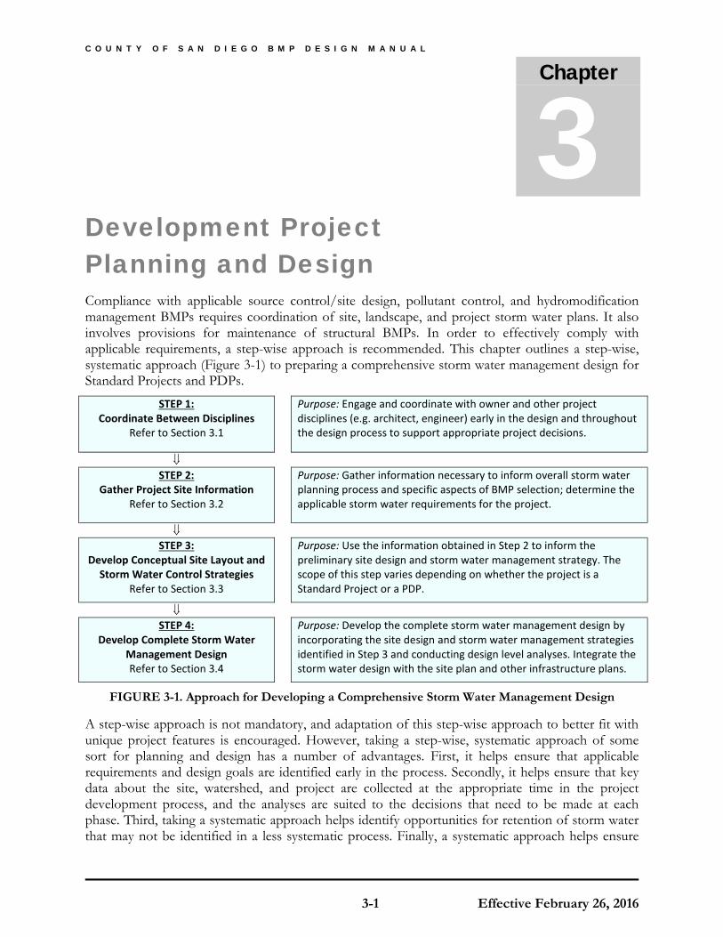
C O U N T Y O F S A N D I E G O B M P D E S I G N M A N U A L
3-1 Effective February 26, 2016
Chapter
3 Development Project Planning and Design Compliance with applicable source control/site design, pollutant control, and hydromodification management BMPs requires coordination of site, landscape, and project storm water plans. It also involves provisions for maintenance of structural BMPs. In order to effectively comply with applicable requirements, a step-wise approach is recommended. This chapter outlines a step-wise, systematic approach (Figure 3-1) to preparing a comprehensive storm water management design for Standard Projects and PDPs.
STEP 1: Coordinate Between Disciplines
Refer to Section 3.1
Purpose: Engage and coordinate with owner and other project disciplines (e.g. architect, engineer) early in the design and throughout the design process to support appropriate project decisions.
⇓ STEP 2:
Gather Project Site Information Refer to Section 3.2
Purpose: Gather information necessary to inform overall storm water planning process and specific aspects of BMP selection; determine the applicable storm water requirements for the project.
⇓ STEP 3:
Develop Conceptual Site Layout and Storm Water Control Strategies
Refer to Section 3.3
Purpose: Use the information obtained in Step 2 to inform the preliminary site design and storm water management strategy. The scope of this step varies depending on whether the project is a Standard Project or a PDP.
⇓ STEP 4:
Develop Complete Storm Water Management Design Refer to Section 3.4
Purpose: Develop the complete storm water management design by incorporating the site design and storm water management strategies identified in Step 3 and conducting design level analyses. Integrate the storm water design with the site plan and other infrastructure plans.
FIGURE 3-1. Approach for Developing a Comprehensive Storm Water Management Design
A step-wise approach is not mandatory, and adaptation of this step-wise approach to better fit with unique project features is encouraged. However, taking a step-wise, systematic approach of some sort for planning and design has a number of advantages. First, it helps ensure that applicable requirements and design goals are identified early in the process. Secondly, it helps ensure that key data about the site, watershed, and project are collected at the appropriate time in the project development process, and the analyses are suited to the decisions that need to be made at each phase. Third, taking a systematic approach helps identify opportunities for retention of storm water that may not be identified in a less systematic process. Finally, a systematic approach helps ensure

Chapter 3: Development Project Planning and Design
3-2 Effective February 26, 2016
that constraints and unintended consequences are considered and used to inform BMP selection and design, and related project decisions.
County-specific special requirements are listed in Section 3.5 and requirements for phased projects are in Section 3.6.
3.1 Coordination between Disciplines Storm water management design requires close coordination between multiple disciplines, as it will affect the site layout and should therefore be coordinated among the project team as necessary from the start. The following list describes entities/disciplines that are frequently involved with storm water management design and potential roles that these entities/disciplines may plan.
Owner:
• Engage the appropriate disciplines needed for the project and facilitate exchange of information between disciplines.
• Identify who will be responsible for long-term maintenance of storm water management features, and initiate maintenance agreements when applicable.
• Ensure that whole lifecycle costs are considered in the selection and design of storm water management features and a source of funding is provided for long term maintenance.
• Identify the party responsible to inspect structural BMPs at each significant construction stage and at completion in order to provide verification of structural BMPs following construction.
Planner: • Communicate overall project planning criteria to the team, such as planned development
density, parking requirements, project-specific planning conditions, conditions of approval from prior entitlement actions (e.g. CEQA, 401 certifications), etc. and locations of open space and conservation easements and environmentally sensitive areas that are protected from disturbance), etc.
• Consider location of storm water facilities early in the conceptual site layout process.
• Assist in developing the site plan.
Architect:
• Participate in siting and design (architectural elements) of storm water BMPs.
Civil Engineer:
• Determine storm water requirements applicable to the site (e.g. Standard Project vs. PDP).
• Obtain site-specific information (e.g. watershed information, infiltration rates) and develop viable storm water management options that meet project requirements.
• Reconcile storm water management requirements with other site requirements (e.g. fire access, Americans with Disabilities Act accessibility, parking, open space).
• Develop site layout and site design including preliminary and final design documents or plans.
Chapter 3: Development Project Planning and Design
3-3 Effective February 26, 2016
• Select and design BMPs; conduct and document associated analyses; prepare BMP design sheets, details, and specifications.
• Prepare project SWQMP submittals.
Landscape Architect and/or Horticulturist/Agronomist:
• Select appropriate plants for vegetated storm water features, BMPs and prepare planting plans.
• Develop specifications for planting, vegetation establishment, and maintenance.
• Assist in developing irrigation plans/rates to minimize water application and non-storm water runoff from the project site.
Geotechnical Engineer
• Assist in preliminary infiltration feasibility screening of the site to help inform project layout and initial BMP selection, including characterizing soil, groundwater, geotechnical hazards, utilities, and any other factors, as applicable for the site.
• Conduct detailed analyses at proposed infiltration BMP locations to confirm or revise feasibility findings and provide design infiltration rates.
• Provide recommendations for infiltration testing that must be conducted during the construction phase, if needed to confirm pre-construction infiltration estimates.
Geomorphologist and/or Geologist
• Provide specialized services, as needed, related to sediment source assessment and/or channel stability or sensitivity assessment.
3.2 Gathering Project Site Information In order to make decisions related to selection and design of storm water management BMPs, it is necessary to gather relevant project site information. This could include physical site information, proposed uses of the site, level of storm water management requirements (i.e. is it a Standard Project or a PDP?), proposed storm water discharge locations, potential/anticipated storm water pollutants based on the proposed uses of the site, receiving water sensitivity to pollutants and susceptibility to erosion, hydromodification management requirements, and other site requirements and constraints.
The amount and type of information that should be collected depends on the project type (i.e. is it a Standard Project, a PDP with all requirements or with only pollutant control requirements?). Refer to Figure 1-1 in Chapter 1 to identify the project type.
Information should only be gathered to the extent necessary to inform the storm water management design. In some cases, it is not necessary to conduct site-specific analyses to precisely characterize conditions. For example, if depth to groundwater is known to be approximately 100 feet based on regional surveys, it is not necessary to also conduct site specific assessment of depth to groundwater to determine whether it is actually 90 feet or 110 feet on the project site. The difference between these values would not influence the storm water management design. In other cases, some information will not be applicable. For example, on an existing development site, there may be no natural hydrologic features remaining, therefore these features do not need to be characterized. The
Chapter 3: Development Project Planning and Design
3-4 Effective February 26, 2016
lack of natural hydrologic features can be simply noted without further effort required.
Checklists (in Appendix I) and submittal templates (in Appendix A) are provided to facilitate gathering information about the project site for BMP selection and design. As part of planning for site investigation, it is helpful to review the subsequent steps (Section 3.3 and 3.4) to gain familiarity with how the site information will be used in making decisions about site layout and storm water BMP selection and design. This can help prioritize the data that are collected.
3.3 Developing Conceptual Site Layout and Storm Water Control Strategies Once preliminary site information has been obtained, the site can be assessed for storm water management opportunities and constraints that will inform the overall site layout. Considering the project site data discussed above, it is essential to identify potential locations for storm water management features at a conceptual level during the site planning phase. Storm water management requirements must be considered as a key factor in laying out the overall site. Preliminary design of permanent storm water BMPs is partially influenced by whether the project is a Standard Project or a PDP. Table 3-1 presents the applicability of different subsections in this Manual based on project type and must be used to determine which requirements apply to a given project.
TABLE 3-1. Applicability of Section 3.3 Sub-sections for Different Project Types
3.3.1 Preliminary Design Steps for All Development Projects
All projects must incorporate source control and site design BMPs. The following systematic approach outlines these site planning considerations for all development projects:
1 Review Chapter 4 of this Manual to become familiar with the menu of source control and site design practices that are required.
2 Review the preliminary site information gathered in Section 3.2, specifically related to:
a. Natural hydrologic features that can be preserved and/or protected;
b. Soil information;
Project Type Section 3.3.1 Section 3.3.2 Section 3.3.3 Section 3.3.4
Standard Project NA NA NA
PDP with only Pollutant Control Requirements
NA
PDP with Pollutant and Hydromodification
Management Requirements

Chapter 3: Development Project Planning and Design
3-5 Effective February 26, 2016
c. General drainage patterns (i.e. general topography, points of connection to the storm drain or receiving water);
d. Pollutant sources that require source controls; and.
e. Summary of site conditions.
3 Create opportunities for source control and site design BMPs by developing an overall conceptual site layout that allocates space for site design BMPs and promotes drainage patterns that are effective for hydrologic control and pollutant source control. For example:
a. Locate pervious areas down gradient from buildings where possible to allow for dispersion.
b. Identify parts of the project that could be drained via overland vegetated conveyance rather than piped connections.
c. Develop traffic circulation patterns that are compatible with minimizing street widths.
4 As part of Section 3.4, refine the selection and placement of source control and site design BMPs and incorporate them into project plans. Compliance with site design and source control requirements must be documented as described in Chapter 4.
3.3.2 Evaluation of Critical Coarse Sediment Yield Areas
For PDPs that are required to meet hydromodification management requirements, evaluate whether critical coarse sediment yield areas exist within or upstream of the project site. Detailed methods for the management of critical coarse sediment yield areas are presented in Chapter 6 a. Conceptual layout of the project site must consider the following items:
a. Have onsite critical coarse sediment areas been identified within the project’s property boundary? Does the proposed project impact these onsite critical coarse sediment areas? What measures are necessary to avoid impacts to these areas? What measures are necessary to allow soil loss from these areas to bypass through the site?
b. Have upstream critical coarse sediment areas been identified upstream of the project’s property boundary? Does the proposed project impact upstream critical coarse sediment areas? What measures are necessary to allow soil loss from these areas to bypass through the site?
c. If onsite and/or upstream sources of critical coarse sediment are not avoided, what measures are necessary to demonstrate no net impact to the receiving water?
d. If impacts to critical coarse sediment areas are not avoided or mitigated for, will a site specific analysis be performed to refine mapping for onsite and/or upstream critical coarse sediment areas?
3.3.3 Drainage Management Areas
Drainage management areas (DMAs) provide an important framework for feasibility screening, BMP prioritization, and storm water management system configuration. BMP selection, sizing, and feasibility determinations must be made at the DMA level; therefore delineation of DMAs is highly recommended at the conceptual site planning phase and is mandatory for completing the project design and meeting submittal requirements. This section provides guidance on delineating DMAs

Chapter 3: Development Project Planning and Design
3-6 Effective February 26, 2016
that is intended to be used as part of Section 3.3 and 3.4.
DMAs are defined based on the proposed drainage patterns of the site and the BMPs to which they drain. During the early phases of the project, DMAs must be delineated based on site drainage patterns and possible BMP locations identified in the site planning process. DMAs should not overlap and should be similar with respect to BMP opportunities and feasibility constraints. More than one DMA can drain to the same BMP. However, because the BMP sizes are determined by the runoff from the DMA, a single DMA may not drain to more than one BMP, unless the BMPs are in series. See Figure 3-2.
FIGURE 3-2. DMA Delineation
In some cases, in early planning phases, it may be appropriate to generalize the proposed treatment plan by simply assigning a certain BMP type to an entire planning area (e.g. Parking lot X will be treated with bioretention) and calculating the total sizing requirement without identifying the specific BMP locations at that time. This planning area would be later subdivided for design-level calculations.
A runoff factor (similar to a “C” factor used in the rational method) should be used to estimate the runoff draining from each DMA. Site design BMPs can be strategically located throughout the project to adjust DCV for sizing pollutant control BMPs. Appendix B provides guidance in estimating the DCV for the drainage area draining to a BMP. Appendix B is recommended for further guidance on placing site design BMPs and delineating DMAs.
DMAs must be established for all areas within the disturbed footprint of the project site. Land use within each DMA should be delineated consistent with the CEQA definition of a “project” to include the “whole of the action” and include all impervious areas in the ultimate build out of the project.
If the ultimate buildout of the project is unknown, the applicant may assign a runoff coefficient to a DMA based upon an assumed percentage of impervious surface. If a future project applicant (e.g., for a building permit) exceeds the impervious area proposed in the original SWQMP an amendment may be required to show that all BMPs are sized to meet all applicable MS4 Permit requirements.
BMPs must be sized to treat the DCV from the total area draining to the BMP, including any offsite

Chapter 3: Development Project Planning and Design
3-7 Effective February 26, 2016
or onsite areas that comingle with project runoff and drains to the BMP. To minimize offsite flows treated by project BMPs, consider diverting upgradient flows in accordance with County drainage, flood control, or other applicable regulation. An example is shown in Figure 3-3.
Section 5.2 provides additional guidance on DMA delineation for pollutant control.
Section 6.3 provides additional guidance on DMA delineation for flow control.

Chapter 3: Development Project Planning and Design
3-8 Effective February 26, 2016
FIGURE 3-3. Tributary Area for BMP Sizing

Chapter 3: Development Project Planning and Design
3-9 Effective February 26, 2016
3.3.4 Developing Conceptual Storm Water Control Strategies
This step applies to PDPs only. The goal of this step is to develop conceptual storm water control strategies that are compatible with the site conditions, including siting and preliminary selection of structural BMPs. At this phase of project planning, it is typically still possible for storm water considerations to influence the site layout to better accommodate storm water design requirements. The end product of this step should be a general, but concrete understanding of the storm water management parameters for each DMA, the compatibility of this approach with the site design, and preliminary estimates of BMP selection. For simpler sites, this step could be abbreviated in favor of skipping forward to design-level analyses in Section 3.4. However, for larger or more complex sites, this section can provide considerable value and help allow evaluation of storm water management requirements on common ground with other site planning considerations.
The following systematic approach is recommended:
1. Review the preliminary site information gathered in Section 3.2, specifically related to information gathered and summarized in the PDP SWQMP Site Information Checklist (Step 3 of PDP SWQMP).
2. Identify self-mitigating, de minimis areas, and potential self-retaining DMAs that can be isolated from the remainder of the site (See Section 5.2).
3. Estimate the DCV for each remaining DMA (See Appendix B.1).
4. Determine if there is a potential opportunity for harvest and use of storm water from the project site. See Section 5.4.1 for harvest and use feasibility screening, which is based on water demand at the project site. For most sites, there is limited opportunity, so evaluating this factor early can help simplify later decisions.
5. Estimate potential runoff reduction and the DCV that could be achieved with site design BMPs (See Section 5.3 and Appendix B.2) and harvest and use BMPs (See Appendix B.3).
6. Based on the remaining runoff after accounting for steps 2 to 5, estimate BMP space requirements. Identify applicable structural BMP requirements (i.e. storm water pollutant control versus hydromodification management) and conduct approximate sizing calculations to determine the overall amount of storage volume and/or footprint area required for BMPs. Use worksheets presented in Appendices B.4 and B.5 to estimate sizing requirements for different types of BMPs.
7. Conduct a preliminary screening of infiltration feasibility conditions to identify areas that are more or less conducive to infiltration. Recommended factors to consider include:
a. Soil types (determined from available geotechnical testing data, soil maps, site observations, and/or other data sources)
b. Approximate infiltration rates at various points on the site, obtained via approximate methods (e.g. simple pit test), if practicable
c. Groundwater elevations
d. Proposed depths of fill
e. New or existing utilities that will remain with development
f. Soil or groundwater contamination issues within the site or in the vicinity of the site

Chapter 3: Development Project Planning and Design
3-10 Effective February 26, 2016
g. Slopes and other potential geotechnical hazards that are unavoidable as part of site development
h. Safety and accessibility considerations
This assessment is not intended to be final or account for all potential factors. Rather, it is intended to help in identifying site opportunities and constraints as they relate to site planning. After potential BMP locations are established, a more detailed feasibility analysis is necessary (see Section 3.4 and 5.4.2). Additionally, Appendix C and D provide methods for geotechnical and groundwater assessment applicable for screening at the planning level and design-level requirements. The County may allow alternate assessment methods with appropriate documentation at its discretion.
8. Identify tentative BMP locations based on preliminary feasibility screening, natural opportunities for BMPs (e.g. low areas of the site, areas near storm drain or stream connections), and other BMP sites that can potentially be created through effective site design (e.g. oddly configured or otherwise unbuildable parcels, easements and landscape amenities including open space and buffers which can double as locations for bioretention or biofiltration facilities).
9. Determine tentative BMP feasibility categories for infiltration for each DMA or specific BMP location. Based on the results of feasibility screening and tentative BMP locations, determine the general feasibility categories that apply to BMPs in these locations. Categories are described in Section 5.4.2 and include:
a. Full infiltration condition;
b. Partial infiltration condition; and
c. No infiltration condition.
Adapt the site layout to attempt to achieve infiltration to the greatest extent feasible.
10. Consider how storm water management BMPs will be accessed for inspection and maintenance and provide necessary site planning allowances (access roads, inspection openings, setbacks, etc.) and coordinate with the County for additional design requirements or allowed BMPs if required for BMPs in public easements or are part of a community facilities district maintained by the County. In addition consider the use of the site. Some BMPs may not be suitable for maintenance by individual home owners.
11. Document site planning and opportunity assessment activities as a record of the decisions that led to the development of the final storm water management plan. The SWQMP primarily shows the complete design rather than the preliminary steps in the process. However, applicants must describe how storm water management objectives have been considered as early as possible in the site planning process and how opportunities to incorporate BMPs have been identified.
3.4 Developing Complete Storm Water Management Design The complete storm water management design consists of all of the elements describing the BMPs to be implemented, as well as integration of the BMPs with the site design and other infrastructure.
Chapter 3: Development Project Planning and Design
3-11 Effective February 26, 2016
The storm water management design must take into consideration the opportunities and constraints identified first during the site planning phase of the project and then during the final design level analysis. The scope of this step varies depending on whether the project is a Standard Project, PDP with only pollutant control BMP requirements or PDP with pollutant control and hydromodification management requirements. The following systematic approach is recommended to develop a final site layout and storm water management design. Table 3-2 presents the applicability of different subsections based on project type and must be used to determine which requirements apply to a given project.
TABLE 3-2. Applicability of Section 3.4 Sub-sections for Different Project Types
3.4.1 Steps for All Development Projects
Standard Projects need to only satisfy the general, source control, and site design requirements of WPO Section 67.811(a) (described in Chapter 4 of this Manual). Applicants should also proceed to Chapter 8 of this Manual to determine submittal requirements.
1. Identify general requirements applicable to the selection and design of BMPs. See Section 4.1.
2. Select, identify and detail specific source control BMPs. See Section 4.2.
3. Select, identify and detail specific site design BMPs. See Section 4.3.
4. Document that all applicable source control and site design BMPs have been used. See Chapter 8.
3.4.2 Steps for PDPs with only Pollutant Control Requirements
The steps below primarily consist of refinements to the conceptual steps completed as part of Section 3.3, accompanied by design-level detail and calculations. More detailed instructions for selection and design of storm water pollutant treatment BMPs are provided in Chapter 5.
1. Select locations for storm water pollutant control BMPs, and delineate and characterize DMAs using information gathered during the site planning phase.
2. Conduct a feasibility analysis for harvest and use BMPs. See Section 5.4.1.
3. Conduct a feasibility analysis for infiltration to determine the infiltration condition. See Section 5.4.2.
Project Type Section 3.4.1 Section 3.4.2 Section 3.4.3
Standard Project NA NA
PDP with only Pollutant Control Requirements NA
PDP with Pollutant Control and Hydromodification Management
Requirements NA

Chapter 3: Development Project Planning and Design
3-12 Effective February 26, 2016
4. Based on the results of steps 2 and 3, select the BMP category that is most appropriate for the site. See Section 5.5.
5. Calculate required BMP sizes and footprints. See Appendix B (sizing methods) and Appendix E (design criteria).
6. Evaluate whether the required BMP footprints will fit within the site considering the site constraints; if not, then document infeasibility and move to the next step.
7. If using biofiltration BMPs, document conformance with the criteria for biofiltration BMPs found in Appendix F, including Appendix F.1, as applicable.
8. If needed, implement flow-thru treatment control BMPs (for use with Offsite Alternative Compliance) for the remaining DCV. See Section 5.5.4 and Appendix B.6 for additional guidance.
9. If flow-thru treatment control BMPs (for use with Offsite Alternative Compliance) were selected, refer to Section 1.8 and Appendix J.
10. Prepare a SWQMP documenting site planning and opportunity assessment activities, final site layout, and storm water management design. See Chapter 8.
11. Determine and document maintenance requirements. See Chapters 7 and 8.
3.4.3 Steps for Projects with Pollutant Control and Hydromodification Management Requirements
The steps below primarily consist of refinements to the conceptual steps completed as part of Section 3.3, accompanied by design-level detail and calculations. More detailed instruction for selection and design of storm water pollutant treatment and hydromodification control BMPs are provided in Chapter 5 and 6, respectively.
1. If critical coarse sediment yield areas were determined to exist within and/or upstream of the project’s property boundary (Section 3.3.2) incorporate appropriate avoidance and bypass measures or demonstrate no net impact to the receiving water when applicable (Section 6.2).
2. Select locations for storm water pollutant control and hydromodification management BMPs and delineate and characterize DMAs using information gathered during the site planning phase.
3. Conduct a feasibility analysis for harvest and use BMPs. See Section 5.4.1.
4. Conduct a feasibility analysis for infiltration to determine the infiltration condition. See Section 5.4.2.
5. Based on the results of steps 3 and 4, select the BMP category for pollutant treatment BMPs that is most appropriate for the site. See Section 5.5.
6. Follow the design approach described in Chapter 3 for integrating storm water pollutant treatment and hydromodification control. The same location(s) can serve both functions (e.g. a biofiltration area that provides both pollutant control and flow control), or separate pollutant control and flow control locations may be identified (e.g. several dispersed retention areas for pollutant control, with overflow directed to a single location of additional storage for flow control).
Chapter 3: Development Project Planning and Design
3-13 Effective February 26, 2016
7. Calculate BMP sizing requirements for pollutant control and flow control. See Appendix B (sizing methods) and Appendix E (design criteria).
a. When the same BMP will serve both functions, Section 6.3.6 of this Manual provides recommendations for assessing the controlling design factor and initiating the design process.
8. Evaluate whether the required BMP footprints will fit within the site considering the site constraints:
a. If they fit within the site, design BMPs to meet applicable sizing and design criteria. Document sizing and design separately for pollutant control and hydromodification management even when the same BMP is serving both functions.
b. If they do not fit the site then document infeasibility and move to the next step.
9. Implement flow-thru treatment control BMPs (for use with Offsite Alternative Compliance) for the remaining DCV. See Section 5.5.4 and Appendix B.6 for additional guidance.
10. If flow-thru treatment control BMPs (for use with Offsite Alternative Compliance) were selected refer to Section 1.8 and Appendix J.
11. Prepare a SWQMP documenting site planning and opportunity assessment activities, final site layout, storm water pollutant control design and hydromodification management design. See Chapter 8.
12. Determine and document maintenance requirements. See Chapters 7 and 8.
3.5 Project Planning and Design Requirements for Other Types of Improvements Offsite Improvements. The term "offsite improvements" refers to improvements constructed offsite from the project area such as access roads, sidewalks, utility lines, and sewers that are within the scope of the project as a whole. Offsite improvements constructed to support a project must be considered part of the whole of the action of the project (see Section 1.3). This includes new offsite impervious areas such as intersection improvements or road widening related to the project. The new offsite impervious areas must be included as part of the collective impervious area of the project even when not contiguous with the project if they are part of the whole of the action of the project (See Section 1.4.1). Offsite improvements that generate pollutants and excess runoff must be addressed with storm water management features, including structural BMPs when the collective project as a whole is a PDP, even when the individual offsite improvement on its own does not meet PDP thresholds.
Interim Improvements are those which are built to serve the project on an interim basis until they are later replaced with permanent or ultimate improvements. Interim improvements that generate pollutants and excess runoff must, like permanent improvements, be addressed with storm water management features, including structural BMPs for the life of the interim improvement. Temporary access roads during construction are not considered interim improvements if they are part of the construction site, and are removed at the termination of construction of the project. Generally, these roads would only be in place on an interim basis of less than one year.
Chapter 3: Development Project Planning and Design
3-14 Effective February 26, 2016
3.6 Phased Projects Phased projects add a layer of complexity to the application process because the master drainage plan often does not include sufficient detail regarding the sequence and details of construction. To facilitate clarity, certain information will be required for each step in the development process of private projects.
Pre-Application. During the Pre-Application process, a handout or other materials describing the requirements to be met for stormwater compliance will be provided or made available to the applicant. These materials outline that the applicant should be aware that depending on construction timing not all phases may end up meeting requirements of the same MS4 Permit. In case a Pre-Application meeting does not occur, the materials will be made available to the applicant along with any other correspondence.
Discretionary Phase. During the discretionary phase, applicants are required to submit the Master PDP SWQMP, the Master HMP Study; the Master Preliminary Grading Plan & Plot Plan, and the Master Preliminary Landscape Plans. These Master Plans must outline the project phasing and demonstrate that required structural BMPs will be in place prior to the occupancy or intended use of the applicable parcels or lots.
Final Engineering Stage. During the Final Engineering stage, with each phased Grading/Improvement Plan submittal (Unit I, etc.), all Discretionary phase Master Plans and Studies (PDP SWQMP, HMP) that originally identified planned structural BMPs should be provided for reference. An outline of completed and future construction phases must also be provided. The applicant must demonstrate either (a) that the project phase currently in Final Engineering (e.g., Unit II) is consistent with assumptions (imperviousness, identified features, etc.) made for that project phase when the Master Plans and Studies were prepared, or (b) that master planned or regional BMPs to serve the phased project area will be constructed to meet applicable performance standards for the project phase. If new impervious areas or other changes to project features will not be mitigated by the storm water features proposed in the Master Plans and Studies, additional storm water features will be required.
Record Plan Stage. At Record Plan stage and during the closeout of each phased portion, one or more Structural BMP Verification Acceptance Packages that include all BMPs identified in the Final Engineering Stage above will be required. The Verification Acceptance Package(s) must identify which BMPs for the phase have previously been constructed and certified, which are being submitted for verification sign-off and, which have yet to be constructed.
3.7 Structural BMPs in the Public Right-of-Way At its discretion, the County may allow Structural BMPs to be constructed in the Public Right-of-way. Permissions to place Structural BMPs in the right-of-way should not be assumed. Applicants are encouraged to check with staff as early as the Pre-Application Meeting or early Discretionary Stage. Section 7.3 provides additional details about maintenance responsibilities for Structural BMPs both within and outside of the right-of-way.

C O U N T Y O F S A N D I E G O B M P D E S I G N M A N U A L
4-1 Effective February 26, 2016
Chapter
4 Source Control and Site Design Requirements for All Development Projects This chapter presents general, source control, and site design requirements to be met by all Standard and PDP projects. Checklists I.4 for source control and I.5 for site design included in Appendix A can be used by both Standard Projects and PDPs to document conformance with these requirements. This Manual should be the first guidance document consulted during the development planning process. A second important County reference related to site design and source control is the Low Impact Development (LID) Handbook. The LID Handbook provides a comprehensive list of LID planning and stormwater management techniques for developers, builders, contractors, planners, landscape architects, engineers, and government employees. It can be found on the County’s website: http://www.sandiegocounty.gov/content/sdc/dpw/watersheds/DevelopmentandConstruction.html
4.1 General Requirements (GR) Per MS4 Permit Provision E.3.a.(1) and WPO Section 67.811(a)(3), BMPs must be designed, constructed and maintained subject to the following criteria:
4.1.1: Onsite BMPs must be located so as to remove pollutants from runoff prior to its discharge to any receiving waters, and as close to the source as possible.
BMP location affects its ability to retain, and/or treat, the pollutants from the contributing drainage area. BMPs must remove pollutants from runoff and should be placed as close to the pollutant source as possible.
How to comply: Projects must implement source control (Section 4.2) and site design BMPs (Section 4.3) that are applicable to their project and site conditions.
4.1.2: Structural BMPs must not be constructed within the Waters of the U.S.
Construction, operation, and maintenance of a structural BMP in a water body can negatively impact the physical, chemical, and biological integrity, as well as the beneficial uses, of the water body. However, offsite alternative compliance opportunities involving restoration of areas within Waters of the U.S. may be identified by the County.
How to comply: Projects must prepare project plans depicting the location of receiving waters and

Chapter 4: Source Control and Site Design Requirements for All Development Projects
4-2 Effective February 26, 2016
proposed BMPs within the project boundary. These plans must demonstrate that storm water BMPs are not located within Waters of the U.S.
4.1.3: Onsite BMPs must be designed and implemented with measures to avoid the creation of nuisances or pollutions associated with vectors (e.g. mosquitos, rodents, or flies).
According to the California Department of Health, structural BMPs that retain standing water for over 96 hours are particularly concerning for facilitating mosquito breeding. Certain site design features that hold standing water may similarly produce mosquitoes.
How to comply: Projects must incorporating design, construction, and maintenance principles demonstrating that they will drain retained water within 96 hours and minimize standing water. Design calculations must be provided to demonstrate the potential for standing water ponding at surface level and accessible to mosquitos has been addressed.
4.2 Source Control (SC) BMP Requirements Source control BMPs avoid and reduce pollutants in storm water runoff. Everyday activities, such as recycling, trash disposal, and irrigation generate potential storm water pollutants. Source control BMPs are defined as activities or features that reduce the potential for storm water runoff to come into contact with pollutants. Per MS4 Permit Provision E.3.a.(2) and WPO Section 67.811(a)(4)), all development projects must implement source control BMPs SC-1 through SC-6 below where applicable and feasible.
How to comply: Projects must implement all source control BMPs that are applicable to their project. Applicability should be determined through a consideration of the development project’s proposed features and the anticipated pollutant sources associated with them. Appendix E provides guidance for identifying source control BMPs applicable to a project. The "Source Control BMP Checklist for All Development Projects" located in Standard and PDP SWQMPs must be used to document compliance with these requirements.
4.2.1 Prevent illicit discharges into the MS4
Per WPO Section 67.804, illicit discharges (i.e., discharges to the MS4 that are not composed entirely of storm water) are prohibited, except as exempted per WPO Section 67.805. Projects must effectively eliminate discharges of non-storm water into: the MS4. The following fact sheets provided in Appendix E describe Source Control BMPs that can be effective in preventing illicit discharges:
• SC-B – Interior floor drains and elevator shaft sump pumps plumbed to sanitary sewer; • SC-C – Interior parking garage floor drains plumbed to sanitary sewers; • SC-E – Pools, spas, ponds with accessible sanitary sewer cleanout; • SC-F – Food service floor mat & equipment cleanout area exposure reduction; • SC-G – Refuse areas exposure reduction; • SC-H – Industrial processes performed indoors; • SC-I – Outdoor storage of equipment or materials exposure reduction; • SC-J – Vehicle and equipment cleaning area exposure reduction; • SC-K – Vehicle/Equipment Repair and Maintenance exposure reduction; • SC-L – Fuel dispensing area coverage and grading requirements;

Chapter 4: Source Control and Site Design Requirements for All Development Projects
4-3 Effective February 26, 2016
• SC-M – Loading dock drainage and coverage requirements; • SC-N – Fire sprinkler test water to sanitary sewer; • SC-O – Miscellaneous drain or wash water not to storm drain system; • SC-6A – Large Trash Generating Facilities BMP guidance; • SC-6B – Animal Facilities BMP guidance; • SC-6C – Plant Nurseries and Garden Centers BMP guidance; and • SC6D – Automotive-related Uses BMP guidance.
Exposure reduction generally requires areas to be covered, to prevent rain exposure; graded to prevent stormwater run-on and run-off; and protection from the wind so that materials are not dispersed.
4.2.2 Identify the storm drain system using stenciling or signage
Storm drain signs and stencils are visible source controls typically placed adjacent to inlets. Posting notices regarding discharge prohibitions at storm drain inlets can prevent waste dumping. Stenciling must be provided for all storm water conveyance system inlets and catch basins within the project area. Inlet stenciling may include concrete stamping, concrete painting, placards, or other methods approved by the County. Some stenciling templates used by the County are attached in Appendix I.4. These may be modified and used as educational pieces promoting improved water quality. In addition to storm drain stenciling, applicants are encouraged to post signs and prohibitive language (with graphical icons) which prohibit illegal dumping at trailheads, parks, building entrances, and public access points along channels and creeks within the project area. The following fact sheet provided in Appendix E provides more information:
• SC-A – Onsite storm drain inlet labelling
4.2.3 Protect outdoor material storage areas from rainfall, run-on, runoff, and wind dispersal
Materials with the potential to pollute storm water runoff must be stored in a manner that prevents contact with rainfall and storm water runoff. All development projects must incorporate the following structural or pollutant control BMPs for outdoor material storage areas, as applicable and feasible:
• Storage areas must be paved and sufficiently impervious to contain leaks and spills, where necessary.
• The storage area must be sloped towards a sump or another equivalent measure that is effective to contain spills.
• Runoff from downspouts/roofs must be directed away from storage areas.
• The storage area must have a roof or awning that extends beyond the storage area to minimize collection of storm water within the secondary containment area. A manufactured storage shed may be used for small containers.
• Use other methods approved by the County.
The following fact sheets provided in Appendix E describe outdoor material storage area BMPs:

Chapter 4: Source Control and Site Design Requirements for All Development Projects
4-4 Effective February 26, 2016
• SC-I – Outdoor storage of equipment or materials exposure reduction; • SC-M – Loading dock drainage and coverage requirements; • SC-O – Miscellaneous drain or wash water not to storm drain system; • SC-6A – Large Trash Generating Facilities BMP guidance; • SC-6B – Animal Facilities BMP guidance; • SC-6C – Plant Nurseries and Garden Centers BMP guidance; and • SC6D – Automotive-related Uses BMP guidance.
4.2.4 Protect materials stored in outdoor work areas from rainfall, run-on, runoff, and wind dispersal
Outdoor work areas have an elevated potential for pollutant loading and spills. All development projects must include the following structural or pollutant control BMPs for any outdoor work areas with potential for pollutant generation, as applicable and feasible:
• Create an impermeable surface such as concrete or asphalt, or a prefabricated metal drip pan, depending on the size needed to protect the materials.
• Cover the area with a roof or other acceptable cover.
• Berm the perimeter of the area to prevent water from adjacent areas from flowing on to the surface of the work area.
• Directly connect runoff to sanitary sewer or other specialized containment system(s), as needed and where feasible. This allows the more highly concentrated pollutants from these areas to receive special treatment that removes particular constituents. Approval for this connection must be obtained from the appropriate sanitary sewer agency.
• Locate the work area away from storm drains or catch basins.
• Use other methods approved by the County. The following fact sheets provided in Appendix E describe materials stored in outdoor work area BMPs:
• SC-F – Food service floor mat & equipment cleanout area exposure reduction; • SC-J – Vehicle and equipment cleaning area exposure reduction; • SC-K – Vehicle/Equipment Repair and Maintenance exposure reduction; • SC-L – Fuel dispensing area coverage and grading requirements; • SC-6A – Large Trash Generating Facilities BMP guidance; • SC-6B – Animal Facilities BMP guidance; • SC-6C – Plant Nurseries and Garden Centers BMP guidance; and • SC6D – Automotive-related Uses BMP guidance.
4.2.5 Protect trash storage areas from rainfall, run-on, runoff, and wind dispersal
Storm water runoff from areas where trash is stored or disposed of can be polluted. In addition, loose trash and debris can be easily transported by water or wind into nearby storm drain inlets, channels, or creeks. All development projects must include the following structural or pollutant

Chapter 4: Source Control and Site Design Requirements for All Development Projects
4-5 Effective February 26, 2016
control BMPs, as applicable:
• Design trash container areas so that drainage from adjoining roofs and pavement is diverted around the area(s) to avoid run-on. This can include berming or grading the waste handling area to prevent run-on of storm water.
• Ensure trash container areas are screened or walled to prevent offsite transport of trash.
• Provide roofs, awnings, or attached lids on all trash containers to minimize direct precipitation and prevent rainfall from entering containers.
• Locate storm drains away from immediate vicinity of the trash storage area and vice versa.
• Post signs on all dumpsters informing users that hazardous material are not to be disposed.
• Use other methods approved by the County. The following fact sheets provided in Appendix E describe trash storage area BMPs:
• SC-G – Refuse areas exposure reduction; • SC-6A – Large Trash Generating Facilities BMP guidance.
4.2.6 Use any additional BMPs determined to be necessary by the County to minimize pollutant generation at each project site
At its discretion, the County may determine that additional on-site controls are necessary to minimize pollutant generation. These determinations will be made on a project-specific basis. Appendix E provides guidance on permanent controls that are applicable at a project site based on potential sources of runoff pollutants at the project site. Applicants must implement all applicable and feasible source control BMPs listed in Appendix E.
4.3 Site Design (SD) BMP Requirements Site design BMPs (also referred to as LID BMPs) are intended to reduce the rate and volume of storm water runoff and associated pollutant loads by minimizing surface soil compaction, reducing impervious surfaces, or providing flow pathways that are “disconnected” from the storm drain system, such as by routing flow over pervious surfaces. Site design BMPs may incorporate interception, storage, evaporation, evapotranspiration, infiltration, and/or filtration processes to retain and/or treat pollutants in storm water before it is discharged from a site.
Applicants are referred to the County of San Diego LID Handbook for additional guidance and information on the incorporation of low impact design features in the design of projects. Appendix K (Guidance for Green Infrastructure) provides additional guidance for implementing green street and other sustainable project features and types. Appendix E also provides the following fact sheets to assist applicants with the proper design of site design features:
• SD-A – Tree Wells • SD-B – Impervious Area Dispersion • SD-C – Green Roofs • SD-D – Permeable Pavement (Site Design BMP) • SD-E – Rain Barrels; and
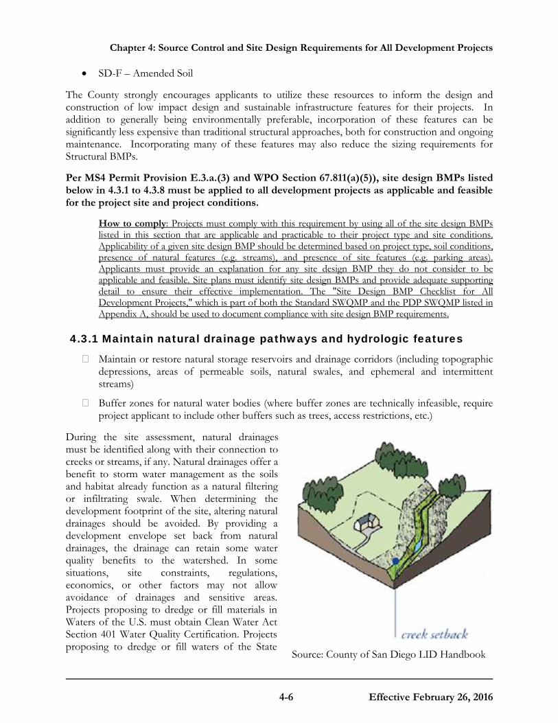
Chapter 4: Source Control and Site Design Requirements for All Development Projects
4-6 Effective February 26, 2016
Source: County of San Diego LID Handbook
• SD-F – Amended Soil
The County strongly encourages applicants to utilize these resources to inform the design and construction of low impact design and sustainable infrastructure features for their projects. In addition to generally being environmentally preferable, incorporation of these features can be significantly less expensive than traditional structural approaches, both for construction and ongoing maintenance. Incorporating many of these features may also reduce the sizing requirements for Structural BMPs.
Per MS4 Permit Provision E.3.a.(3) and WPO Section 67.811(a)(5)), site design BMPs listed below in 4.3.1 to 4.3.8 must be applied to all development projects as applicable and feasible for the project site and project conditions.
How to comply: Projects must comply with this requirement by using all of the site design BMPs listed in this section that are applicable and practicable to their project type and site conditions. Applicability of a given site design BMP should be determined based on project type, soil conditions, presence of natural features (e.g. streams), and presence of site features (e.g. parking areas). Applicants must provide an explanation for any site design BMP they do not consider to be applicable and feasible. Site plans must identify site design BMPs and provide adequate supporting detail to ensure their effective implementation. The "Site Design BMP Checklist for All Development Projects," which is part of both the Standard SWQMP and the PDP SWQMP listed in Appendix A, should be used to document compliance with site design BMP requirements.
4.3.1 Maintain natural drainage pathways and hydrologic features
� Maintain or restore natural storage reservoirs and drainage corridors (including topographic depressions, areas of permeable soils, natural swales, and ephemeral and intermittent streams)
� Buffer zones for natural water bodies (where buffer zones are technically infeasible, require project applicant to include other buffers such as trees, access restrictions, etc.)
During the site assessment, natural drainages must be identified along with their connection to creeks or streams, if any. Natural drainages offer a benefit to storm water management as the soils and habitat already function as a natural filtering or infiltrating swale. When determining the development footprint of the site, altering natural drainages should be avoided. By providing a development envelope set back from natural drainages, the drainage can retain some water quality benefits to the watershed. In some situations, site constraints, regulations, economics, or other factors may not allow avoidance of drainages and sensitive areas. Projects proposing to dredge or fill materials in Waters of the U.S. must obtain Clean Water Act Section 401 Water Quality Certification. Projects proposing to dredge or fill waters of the State

Chapter 4: Source Control and Site Design Requirements for All Development Projects
4-7 Effective February 26, 2016
must obtain waste discharge requirements. Both the 401 Certification and the Waste Discharge Requirements are administered by the San Diego Water Board.
A setback of 50-200 feet is recommended for development proposed adjacent to Waters of the U.S depending on the type of Water of the U.S. For further guidance, refer to the County of San Diego Guidelines for Determining Significance and Report Format and Content Requirements Biological Resources last revised in September 15, 2010. This document can be found at http://www.sandiegocounty.gov/content/dam/sdc/pds/ProjectPlanning/docs/Biological_Guidelines.pdf.
Projects can incorporate maintenance of natural drainage pathways and hydrologic features into a project by implementing the following planning and design phase techniques:
• Evaluate surface drainage and topography in considering selection of Site Design BMPs that will be most beneficial for a given project site. Where feasible, maintain topographic depressions for infiltration.
• Optimize the existing site layout and reduce the need for grading. Where possible, conform the site layout along natural landforms, avoid grading and disturbance of vegetation and soils, and replicate the site’s natural drainage patterns. Integrating existing drainage patterns into the site plan will help maintain the site’s predevelopment hydrologic function and may reduce construction costs.
• Preserve existing drainage paths and depressions to maintain the time of concentration and infiltration rates of runoff, and decrease peak flow.
• Do not locate structural BMPs in buffer zones if a State or Federal resource agency (SDRWQCB, California Department of Fish and Wildlife; U.S. Army Corps of Engineers, etc.) prohibits maintenance or activity in the area.
4.3.2 Conserve natural areas, soils and vegetation
� Conserve natural areas within the project footprint including existing trees, other vegetation, and soils
To enhance a site’s ability to support source control and reduce runoff, the conservation and restoration of natural areas must be considered in the site design process. By conserving or restoring the natural drainage features, natural processes are able to intercept storm water, thereby reducing the amount of runoff.
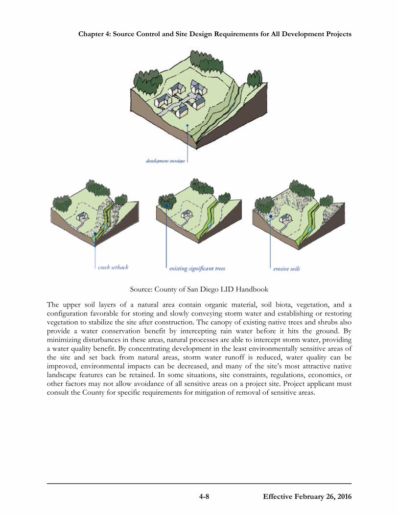
Chapter 4: Source Control and Site Design Requirements for All Development Projects
4-8 Effective February 26, 2016
Source: County of San Diego LID Handbook
The upper soil layers of a natural area contain organic material, soil biota, vegetation, and a configuration favorable for storing and slowly conveying storm water and establishing or restoring vegetation to stabilize the site after construction. The canopy of existing native trees and shrubs also provide a water conservation benefit by intercepting rain water before it hits the ground. By minimizing disturbances in these areas, natural processes are able to intercept storm water, providing a water quality benefit. By concentrating development in the least environmentally sensitive areas of the site and set back from natural areas, storm water runoff is reduced, water quality can be improved, environmental impacts can be decreased, and many of the site’s most attractive native landscape features can be retained. In some situations, site constraints, regulations, economics, or other factors may not allow avoidance of all sensitive areas on a project site. Project applicant must consult the County for specific requirements for mitigation of removal of sensitive areas.
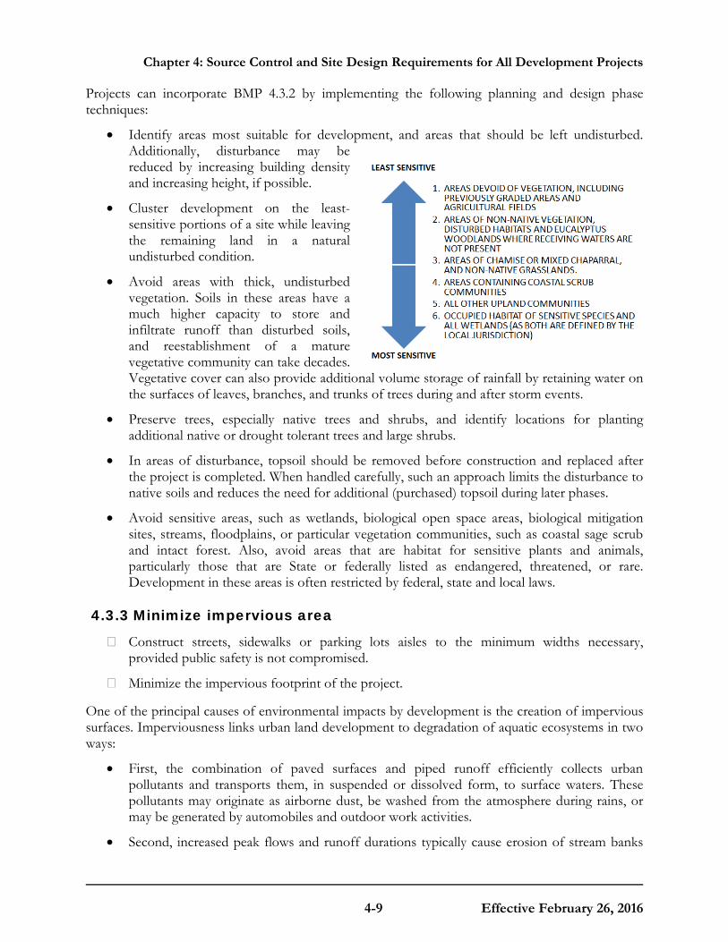
Chapter 4: Source Control and Site Design Requirements for All Development Projects
4-9 Effective February 26, 2016
Projects can incorporate BMP 4.3.2 by implementing the following planning and design phase techniques:
• Identify areas most suitable for development, and areas that should be left undisturbed. Additionally, disturbance may be reduced by increasing building density and increasing height, if possible.
• Cluster development on the least-sensitive portions of a site while leaving the remaining land in a natural undisturbed condition.
• Avoid areas with thick, undisturbed vegetation. Soils in these areas have a much higher capacity to store and infiltrate runoff than disturbed soils, and reestablishment of a mature vegetative community can take decades. Vegetative cover can also provide additional volume storage of rainfall by retaining water on the surfaces of leaves, branches, and trunks of trees during and after storm events.
• Preserve trees, especially native trees and shrubs, and identify locations for planting additional native or drought tolerant trees and large shrubs.
• In areas of disturbance, topsoil should be removed before construction and replaced after the project is completed. When handled carefully, such an approach limits the disturbance to native soils and reduces the need for additional (purchased) topsoil during later phases.
• Avoid sensitive areas, such as wetlands, biological open space areas, biological mitigation sites, streams, floodplains, or particular vegetation communities, such as coastal sage scrub and intact forest. Also, avoid areas that are habitat for sensitive plants and animals, particularly those that are State or federally listed as endangered, threatened, or rare. Development in these areas is often restricted by federal, state and local laws.
4.3.3 Minimize impervious area
� Construct streets, sidewalks or parking lots aisles to the minimum widths necessary, provided public safety is not compromised.
� Minimize the impervious footprint of the project.
One of the principal causes of environmental impacts by development is the creation of impervious surfaces. Imperviousness links urban land development to degradation of aquatic ecosystems in two ways:
• First, the combination of paved surfaces and piped runoff efficiently collects urban pollutants and transports them, in suspended or dissolved form, to surface waters. These pollutants may originate as airborne dust, be washed from the atmosphere during rains, or may be generated by automobiles and outdoor work activities.
• Second, increased peak flows and runoff durations typically cause erosion of stream banks
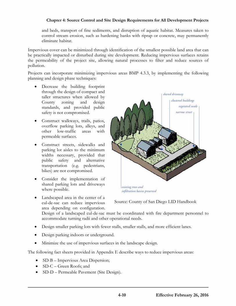
Chapter 4: Source Control and Site Design Requirements for All Development Projects
4-10 Effective February 26, 2016
Source: County of San Diego LID Handbook
and beds, transport of fine sediments, and disruption of aquatic habitat. Measures taken to control stream erosion, such as hardening banks with riprap or concrete, may permanently eliminate habitat.
Impervious cover can be minimized through identification of the smallest possible land area that can be practically impacted or disturbed during site development. Reducing impervious surfaces retains the permeability of the project site, allowing natural processes to filter and reduce sources of pollution.
Projects can incorporate minimizing impervious areas BMP 4.3.3, by implementing the following planning and design phase techniques:
• Decrease the building footprint through the design of compact and taller structures when allowed by County zoning and design standards, and provided public safety is not compromised.
• Construct walkways, trails, patios, overflow parking lots, alleys, and other low-traffic areas with permeable surfaces.
• Construct streets, sidewalks and parking lot aisles to the minimum widths necessary, provided that public safety and alternative transportation (e.g. pedestrians, bikes) are not compromised.
• Consider the implementation of shared parking lots and driveways where possible.
• Landscaped area in the center of a cul-de-sac can reduce impervious area depending on configuration. Design of a landscaped cul-de-sac must be coordinated with fire department personnel to accommodate turning radii and other operational needs.
• Design smaller parking lots with fewer stalls, smaller stalls, and more efficient lanes.
• Design parking indoors or underground.
• Minimize the use of impervious surfaces in the landscape design.
The following fact sheets provided in Appendix E describe ways to reduce impervious areas:
• SD-B – Impervious Area Dispersion; • SD-C – Green Roofs; and • SD-D – Permeable Pavement (Site Design).
Chapter 4: Source Control and Site Design Requirements for All Development Projects
4-11 Effective February 26, 2016
4.3.4 Minimize soil compaction
� Minimize soil compaction in landscaped areas The upper soil layers contain organic material, soil biota, and a configuration favorable for storing and slowly conveying storm water down gradient. By protecting native soils and vegetation in appropriate areas during clearing and grading the site can retain some of its existing beneficial hydrologic function. Soil compaction resulting from the movement of heavy construction equipment can reduce soil infiltration rates. It is important to recognize that areas adjacent to and under building foundations, roads and manufactured slopes must be compacted with minimum soil density requirements in compliance with County building and grading ordinances.
Projects can reduce soil compaction by implementing the following planning and design phase techniques:
• Avoid disturbance in planned green space and proposed landscaped areas where feasible. Areas that are planned for retaining their beneficial hydrological function should be protected during the grading and construction phase so that vehicles and construction equipment do not intrude and inadvertently compact the area.
• In areas planned for landscaping where compaction cannot be avoided, re-till the soil surface to allow for better infiltration capacity. Soil amendments are recommended and may be necessary to increase permeability and organic content. Soil stability, density requirements, and other geotechnical considerations associated with soil compaction must be reviewed by a qualified landscape architect or licensed geotechnical, civil or other professional engineer.
The following fact sheet provided in Appendix E provides more information:
• SD-F Amended Soil
4.3.5 Disperse impervious areas
� Disconnect impervious surfaces through distributed pervious areas.
� Design and construct landscaped or other pervious areas to effectively receive and infiltrate, retain and/or treat runoff from impervious areas prior to discharging to the MS4
Impervious area dispersion (dispersion) refers to the practice of disconnecting impervious areas from directly draining to the storm drain system by routing runoff from impervious areas such as rooftops, walkways, and driveways onto the surface of adjacent pervious areas. The intent is to slow runoff discharges, and reduce volumes while achieving incidental treatment. Volume reduction from dispersion is dependent on the infiltration characteristics of the pervious area and the amount of impervious area draining to the pervious area. Treatment is achieved through filtration, shallow sedimentation, sorption, infiltration, evapotranspiration, biochemical processes and plant uptake.
The effects of imperviousness can be mitigated by disconnecting impervious areas from the drainage system and by encouraging detention and retention of runoff near the point where it is generated. Detention and retention of runoff reduces peak flows and volumes and allows pollutants to settle out or adhere to soils before they can be transported downstream. Disconnection practices may be applied in almost any location, but impervious surfaces must discharge into a suitable receiving area for the practices to be effective. Information gathered during the site assessment will help determine appropriate receiving areas.
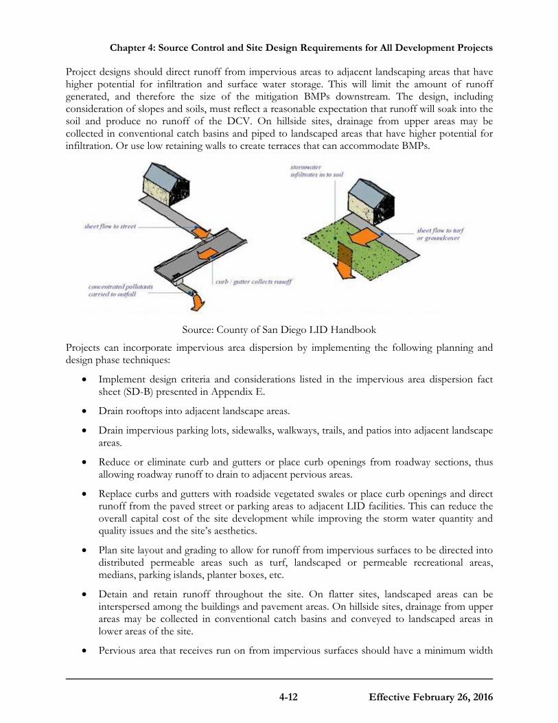
Chapter 4: Source Control and Site Design Requirements for All Development Projects
4-12 Effective February 26, 2016
Project designs should direct runoff from impervious areas to adjacent landscaping areas that have higher potential for infiltration and surface water storage. This will limit the amount of runoff generated, and therefore the size of the mitigation BMPs downstream. The design, including consideration of slopes and soils, must reflect a reasonable expectation that runoff will soak into the soil and produce no runoff of the DCV. On hillside sites, drainage from upper areas may be collected in conventional catch basins and piped to landscaped areas that have higher potential for infiltration. Or use low retaining walls to create terraces that can accommodate BMPs.
Source: County of San Diego LID Handbook
Projects can incorporate impervious area dispersion by implementing the following planning and design phase techniques:
• Implement design criteria and considerations listed in the impervious area dispersion fact sheet (SD-B) presented in Appendix E.
• Drain rooftops into adjacent landscape areas.
• Drain impervious parking lots, sidewalks, walkways, trails, and patios into adjacent landscape areas.
• Reduce or eliminate curb and gutters or place curb openings from roadway sections, thus allowing roadway runoff to drain to adjacent pervious areas.
• Replace curbs and gutters with roadside vegetated swales or place curb openings and direct runoff from the paved street or parking areas to adjacent LID facilities. This can reduce the overall capital cost of the site development while improving the storm water quantity and quality issues and the site’s aesthetics.
• Plan site layout and grading to allow for runoff from impervious surfaces to be directed into distributed permeable areas such as turf, landscaped or permeable recreational areas, medians, parking islands, planter boxes, etc.
• Detain and retain runoff throughout the site. On flatter sites, landscaped areas can be interspersed among the buildings and pavement areas. On hillside sites, drainage from upper areas may be collected in conventional catch basins and conveyed to landscaped areas in lower areas of the site.
• Pervious area that receives run on from impervious surfaces should have a minimum width
Chapter 4: Source Control and Site Design Requirements for All Development Projects
4-13 Effective February 26, 2016
of 10 feet and a maximum slope of 5%.
The following fact sheet provided in Appendix E provides more information:
• SD-B- Impervious area dispersion
4.3.6 Collect runoff
� Use small collection strategies located at, or as close to as possible to the sources (i.e. the point where storm water initially meets the ground) to minimize the transport of runoff and pollutants to the MS4 and receiving waters
� Use permeable material for projects with low traffic areas and appropriate soil conditions
Distributed control of storm water runoff from the site can be accomplished by applying small collection techniques (e.g. green roofs), or integrated management practices, on small sub-catchments or on residential lots. Small collection techniques foster opportunities to maintain the natural hydrology provide a much greater range of control practices. Integration of storm water management into landscape design and natural features of the site, reduce site development and long-term maintenance costs, and provide redundancy if one technique fails. On flatter sites, it typically works best to intersperse landscaped areas and integrate small scale retention practices among the buildings and paving.
Permeable pavements contain small voids that allow water to pass through to a gravel base. They come in a variety of forms; they may be a modular paving system (concrete pavers, grass-pave, or gravel-pave) or poured in place pavement (porous concrete, permeable asphalt). Project applicants should identify locations where permeable pavements could be substituted for impervious concrete or asphalt paving. In areas where infiltration is not appropriate, permeable paving systems can be fitted with an under drain to allow filtration, storage, and evaporation, prior to drainage into the storm drain system.
Projects can incorporate runoff collection by implementing the following planning and design phase techniques:
• Implementing distributed small collection techniques to collect and retain runoff (see SD-E Rain Barrels in Appendix E)
• Installing permeable pavements (see SD-D Permeable Pavement in Appendix E)
4.3.7 Landscape with native or drought tolerant species
In accordance with the County’s Watershed Protection Ordinance and Water Conservation in Landscaping Ordinance5, applicants should select a landscape design and plant palette that minimizes required resources (irrigation, fertilizers and pesticides). Native plants require less fertilizer and pesticide use because they are already adapted to local rainfall patterns and soils conditions. Plants should be selected to be drought tolerant and to not require watering after establishment (2 to 3 years). After plants are established, watering should only be required during
5 Available online at http://www.sandiegocounty.gov/pds/Landscape-Ordinance_Design_Review_Manual.html
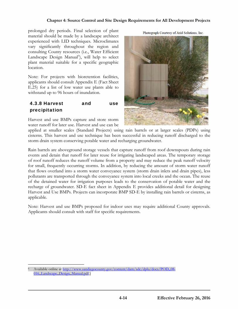
Chapter 4: Source Control and Site Design Requirements for All Development Projects
4-14 Effective February 26, 2016
prolonged dry periods. Final selection of plant material should be made by a landscape architect experienced with LID techniques. Microclimates vary significantly throughout the region and consulting County resources (i.e., Water Efficient Landscape Design Manual6), will help to select plant material suitable for a specific geographic location.
Note: For projects with bioretention facilities, applicants should consult Appendix E (Fact Sheet E.25) for a list of low water use plants able to withstand up to 96 hours of inundation.
4.3.8 Harvest and use precipitation
Harvest and use BMPs capture and store storm water runoff for later use. Harvest and use can be applied at smaller scales (Standard Projects) using rain barrels or at larger scales (PDPs) using cisterns. This harvest and use technique has been successful in reducing runoff discharged to the storm drain system conserving potable water and recharging groundwater.
Rain barrels are aboveground storage vessels that capture runoff from roof downspouts during rain events and detain that runoff for later reuse for irrigating landscaped areas. The temporary storage of roof runoff reduces the runoff volume from a property and may reduce the peak runoff velocity for small, frequently occurring storms. In addition, by reducing the amount of storm water runoff that flows overland into a storm water conveyance system (storm drain inlets and drain pipes), less pollutants are transported through the conveyance system into local creeks and the ocean. The reuse of the detained water for irrigation purposes leads to the conservation of potable water and the recharge of groundwater. SD-E fact sheet in Appendix E provides additional detail for designing Harvest and Use BMPs. Projects can incorporate BMP SD-E by installing rain barrels or cisterns, as applicable.
Note: Harvest and use BMPs proposed for indoor uses may require additional County approvals. Applicants should consult with staff for specific requirements.
6 Available online at http://www.sandiegocounty.gov/content/dam/sdc/dplu/docs/POD_08-
016_Landscape_Design_Manual.pdf.)
C O U N T Y O F S A N D I E G O B M P D E S I G N M A N U A L
5-1 Effective February 26, 2016
Chapter
5 Storm Water Pollutant Control Requirements for PDPs In addition to the site design and source control BMPs discussed in Chapter 4, PDPs are required to implement storm water pollutant control BMPs to reduce the quantity of pollutants in storm water discharges. Storm water pollutant control BMPs are engineered facilities that are designed to retain (i.e. intercept, store, infiltrate, evaporate, and evapotranspire), biofilter, and/or provide flow-thru treatment of storm water runoff generated on the project site.
This chapter describes a specific process for determining which category of pollutant control BMP, or combination of BMPs, is most appropriate for the PDP site and how to design the BMP to meet the storm water pollutant control performance standard (per Section 2.2).
This chapter by itself is not a complete design guide for project development. It is intended to provide guidance for selecting and designing storm water pollutant control BMPs. Specifically:
• This chapter should be followed after having conducted site planning that maximizes opportunities for storm water retention and biofiltration as discussed in Chapter 3.
• The steps in this chapter pertain specifically to storm water pollutant control BMPs. These criteria must be met regardless of whether or not hydromodification management applies, however the overall sequencing of project development may be different if hydromodification management applies. For guidance on how to integrate both hydromodification management and pollutant control BMPs (in cases where both requirements apply), see Sections 3.4.3, 5.6 and Chapter 6.
5.1 Steps for Selecting and Designing Storm Water Pollutant Control BMPs Figures 5-1 and 5-2 present flow charts for complying with storm water pollutant control BMP requirements. The steps associated with these flow charts are described below. A project is considered to be in compliance with storm water pollutant control performance standards if it follows and implements this flow chart and follows the supporting technical guidance referenced from this flow chart. This section is applicable whether or not hydromodification management requirements apply, however the overall sequencing of project development may be different if hydromodification management requirements apply.

Chapter 5: Storm Water Pollutant Control Requirements for PDPs
5-2 Effective February 26, 2016
FIGURE 5-1. Storm Water Pollutant Control BMP Selection Flow Chart
See Figure 5-2

Chapter 5: Storm Water Pollutant Control Requirements for PDPs
5-3 Effective February 26, 2016
7 FIGURE 5-2. Storm Water Pollutant Control BMP Selection Flow Chart
* Project approval at the discretion of the County.
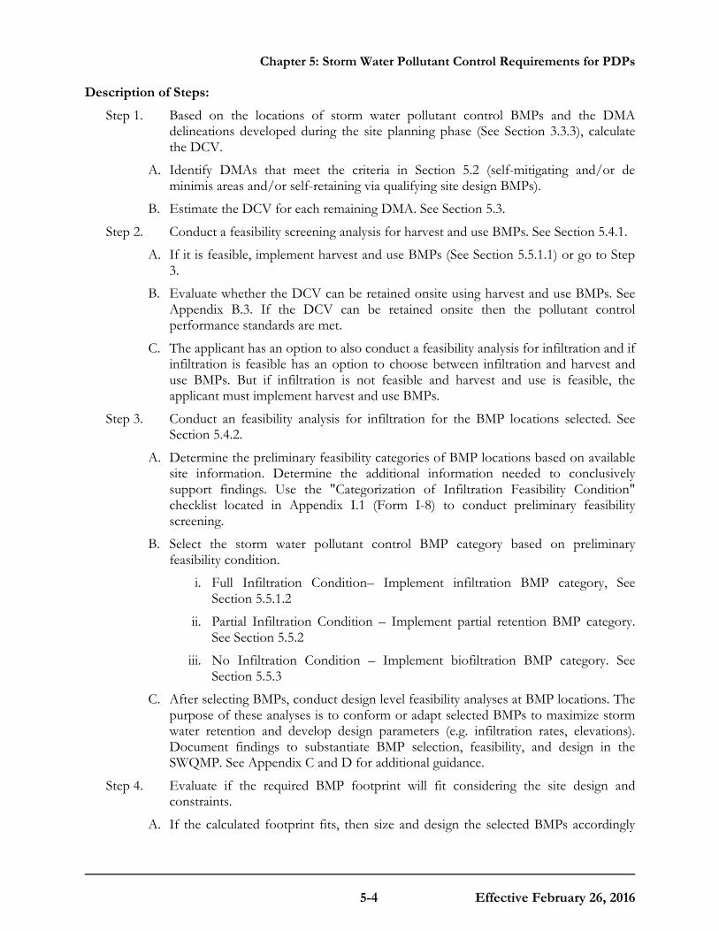
Chapter 5: Storm Water Pollutant Control Requirements for PDPs
5-4 Effective February 26, 2016
Description of Steps:
Step 1. Based on the locations of storm water pollutant control BMPs and the DMA delineations developed during the site planning phase (See Section 3.3.3), calculate the DCV.
A. Identify DMAs that meet the criteria in Section 5.2 (self-mitigating and/or de minimis areas and/or self-retaining via qualifying site design BMPs).
B. Estimate the DCV for each remaining DMA. See Section 5.3.
Step 2. Conduct a feasibility screening analysis for harvest and use BMPs. See Section 5.4.1.
A. If it is feasible, implement harvest and use BMPs (See Section 5.5.1.1) or go to Step 3.
B. Evaluate whether the DCV can be retained onsite using harvest and use BMPs. See Appendix B.3. If the DCV can be retained onsite then the pollutant control performance standards are met.
C. The applicant has an option to also conduct a feasibility analysis for infiltration and if infiltration is feasible has an option to choose between infiltration and harvest and use BMPs. But if infiltration is not feasible and harvest and use is feasible, the applicant must implement harvest and use BMPs.
Step 3. Conduct an feasibility analysis for infiltration for the BMP locations selected. See Section 5.4.2.
A. Determine the preliminary feasibility categories of BMP locations based on available site information. Determine the additional information needed to conclusively support findings. Use the "Categorization of Infiltration Feasibility Condition" checklist located in Appendix I.1 (Form I-8) to conduct preliminary feasibility screening.
B. Select the storm water pollutant control BMP category based on preliminary feasibility condition.
i. Full Infiltration Condition– Implement infiltration BMP category, See Section 5.5.1.2
ii. Partial Infiltration Condition – Implement partial retention BMP category. See Section 5.5.2
iii. No Infiltration Condition – Implement biofiltration BMP category. See Section 5.5.3
C. After selecting BMPs, conduct design level feasibility analyses at BMP locations. The purpose of these analyses is to conform or adapt selected BMPs to maximize storm water retention and develop design parameters (e.g. infiltration rates, elevations). Document findings to substantiate BMP selection, feasibility, and design in the SWQMP. See Appendix C and D for additional guidance.
Step 4. Evaluate if the required BMP footprint will fit considering the site design and constraints.
A. If the calculated footprint fits, then size and design the selected BMPs accordingly

Chapter 5: Storm Water Pollutant Control Requirements for PDPs
5-5 Effective February 26, 2016
using design criteria and considerations from fact sheets presented in Appendix E. The project has met the pollutant control performance standards.
B. If the calculated BMP footprint does not fit, evaluate additional options to make space for BMPs. Examples include potential design revisions, reconfiguring DMAs, evaluating other or additional BMP locations and evaluating other BMP types. If no additional options are practicable for making adequate space for the BMPs, then document why the remaining DCV could not be treated onsite and then implement the BMP using the maximum feasible footprint, design criteria and considerations from fact sheets presented in Appendix E then continue to the next step. The County reserves the right to reject a proposal if the entire DCV cannot be treated because the BMP size could not fit within the project footprint.
Step 5. Implement flow-thru treatment control BMPs for the remaining DCV. See Section 5.5.4 and B.6 for additional guidance.
A. When flow-thru treatment control BMPs are implemented the project applicant must also participate in an offsite alternative compliance program. See Section 1.8 and Appendix J.
Step 6. Prepare a SWQMP documenting site planning and opportunity assessment activities, final site layout and storm water management design. See Chapter 8.
Step 7. Identify and document maintenance requirements and confirm acceptability to the responsible party. See Chapters 7 and Chapter 8.
5.2 DMAs Excluded from DCV Calculation Applicants may exclude DMAs from DCV calculations if they meet the criteria specified below. However, each DMA must implement source control and site design BMPs as applicable and feasible. These exemptions will be evaluated on a case-by-case basis at the discretion of the County.
5.2.1 Self-mitigating DMAs
Self-mitigating DMAs consist of natural or landscaped areas that drain directly offsite or to the public storm drain system. Self-mitigating DMAs must meet ALL of the following to be eligible for exclusion:
• Vegetation in the natural or landscaped area is native and/or non-native/non-invasive drought tolerant species that do not require regular application of fertilizers and pesticides.
• Soils are undisturbed native topsoil, or disturbed soils that have been amended and aerated to promote water retention characteristics equivalent to undisturbed native topsoil.
• The incidental impervious areas are less than 5 percent of the self-mitigating area.
• Impervious area within the self-mitigated area should not be hydraulically connected to other impervious areas unless it is a storm water conveyance system (such as a brow ditch).
• The self-mitigating area is hydraulically separate from DMAs that contain permanent storm water pollutant control BMPs.
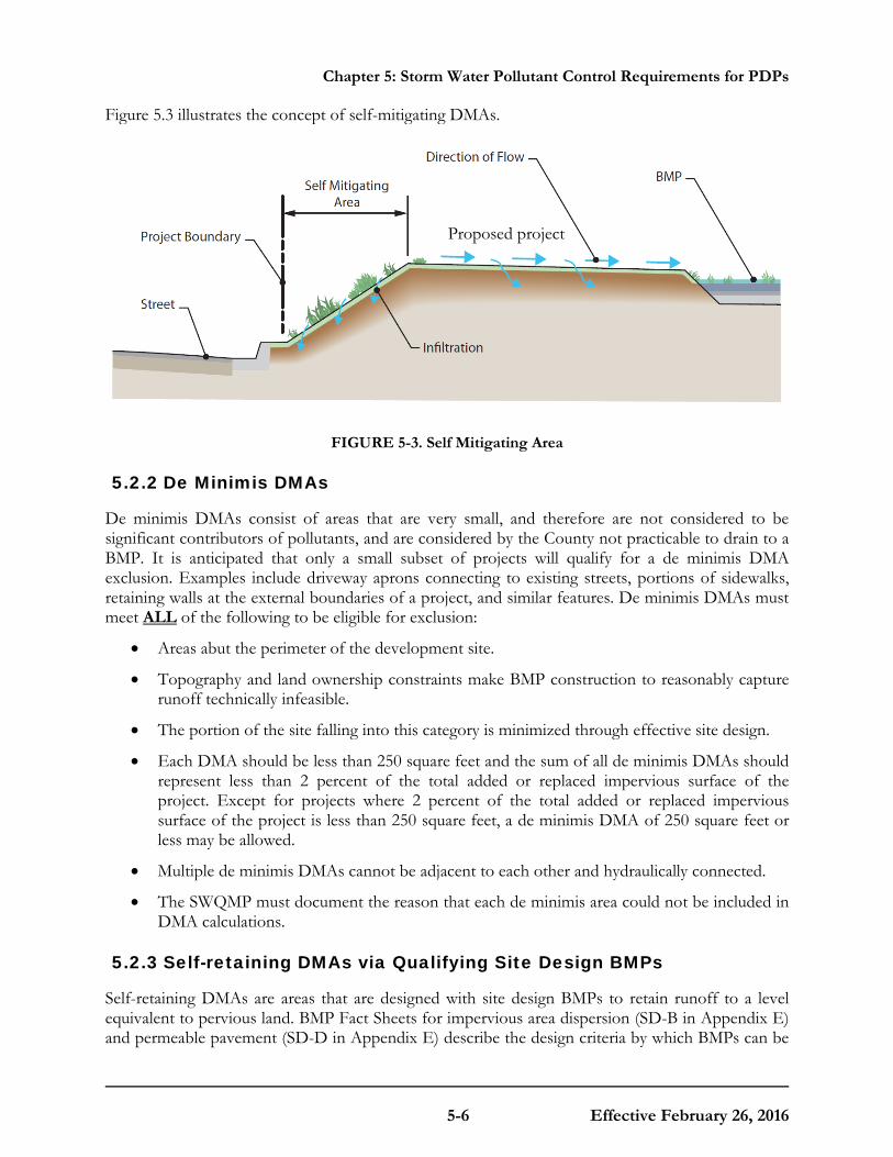
Chapter 5: Storm Water Pollutant Control Requirements for PDPs
5-6 Effective February 26, 2016
Figure 5.3 illustrates the concept of self-mitigating DMAs.
FIGURE 5-3. Self Mitigating Area
5.2.2 De Minimis DMAs
De minimis DMAs consist of areas that are very small, and therefore are not considered to be significant contributors of pollutants, and are considered by the County not practicable to drain to a BMP. It is anticipated that only a small subset of projects will qualify for a de minimis DMA exclusion. Examples include driveway aprons connecting to existing streets, portions of sidewalks, retaining walls at the external boundaries of a project, and similar features. De minimis DMAs must meet ALL of the following to be eligible for exclusion:
• Areas abut the perimeter of the development site.
• Topography and land ownership constraints make BMP construction to reasonably capture runoff technically infeasible.
• The portion of the site falling into this category is minimized through effective site design.
• Each DMA should be less than 250 square feet and the sum of all de minimis DMAs should represent less than 2 percent of the total added or replaced impervious surface of the project. Except for projects where 2 percent of the total added or replaced impervious surface of the project is less than 250 square feet, a de minimis DMA of 250 square feet or less may be allowed.
• Multiple de minimis DMAs cannot be adjacent to each other and hydraulically connected.
• The SWQMP must document the reason that each de minimis area could not be included in DMA calculations.
5.2.3 Self-retaining DMAs via Qualifying Site Design BMPs
Self-retaining DMAs are areas that are designed with site design BMPs to retain runoff to a level equivalent to pervious land. BMP Fact Sheets for impervious area dispersion (SD-B in Appendix E) and permeable pavement (SD-D in Appendix E) describe the design criteria by which BMPs can be
Proposed project

Chapter 5: Storm Water Pollutant Control Requirements for PDPs
5-7 Effective February 26, 2016
considered self-retaining. DMAs that are categorized as self-retaining DMAs are considered to only meet the storm water pollutant control obligations.
Requirements for utilizing this category of DMA:
• Site design BMPs such as impervious area dispersion and permeable pavement may be used individually or in combination to reduce or eliminate runoff from a portion of a PDP.
• If a site design BMP is used to create a self-retaining DMA, then the site design BMPs must be designed and implemented per the guidelines in the applicable fact sheet. These criteria are conservatively developed to anticipate potential changes in DMA characteristics with time. The fact sheet criteria for impervious area dispersion and permeable pavement for meeting pollutant control requirement developed using continuous simulation are summarized below:
o SD-B Impervious Area Dispersion: a DMA is considered self-retaining if the impervious to pervious ratio is:
2:1 when the pervious area is composed of Hydrologic Soil Group A
1:1 when the pervious area is composed of Hydrologic Soil Group B
o SD-D Self-retaining permeable pavement: a DMA is considered self-retaining if the ratio of total drainage area (including permeable pavement) to area of permeable pavement is 1.5:1 or less.
o Note: Left side of ratios presented above represents the portion of the site that receives volume reduction and the right side of the ratio represents the site design BMP that promotes the achieved volume reduction.
• Site design BMPs used as part of a self-retaining DMA or as part of reducing runoff coefficients from a DMA must be clearly called out on project plans and in the SWQMP.
• The County may accept or reject a proposed self-retaining DMA meeting these criteria at its discretion. Examples of rationales for rejection may include the potential for negative impacts (such as infiltration or vector issues), potential for significant future alteration of this feature, or inability to visually inspect and confirm the feature.
• For PDPs subject to hydromodification requirements, please note that Self-retaining DMAs must be included in the hydromodification analysis. Reductions in DCV realized through Site Design BMPs are applicable to treatment control only and do not apply to hydromodification requirements.
Other site design BMPs can be considered self-retaining for meeting storm water pollutant control obligations if the long term annual runoff volume (estimated using continuous simulation following guidelines listed in Appendix G) from the DMA is reduced to a level equivalent to pervious land and the applicant provides supporting analysis and rationale for the reduction in long term runoff volume. Approval of other self-retaining areas is at the discretion of the County. Figure 5.4 illustrates the concept of self-retaining DMAs.
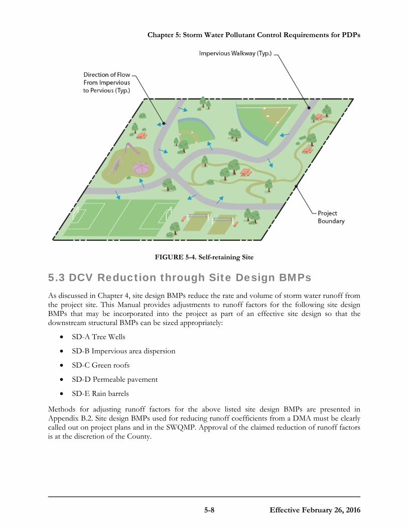
Chapter 5: Storm Water Pollutant Control Requirements for PDPs
5-8 Effective February 26, 2016
FIGURE 5-4. Self-retaining Site
5.3 DCV Reduction through Site Design BMPs As discussed in Chapter 4, site design BMPs reduce the rate and volume of storm water runoff from the project site. This Manual provides adjustments to runoff factors for the following site design BMPs that may be incorporated into the project as part of an effective site design so that the downstream structural BMPs can be sized appropriately:
• SD-A Tree Wells
• SD-B Impervious area dispersion
• SD-C Green roofs
• SD-D Permeable pavement
• SD-E Rain barrels
Methods for adjusting runoff factors for the above listed site design BMPs are presented in Appendix B.2. Site design BMPs used for reducing runoff coefficients from a DMA must be clearly called out on project plans and in the SWQMP. Approval of the claimed reduction of runoff factors is at the discretion of the County.

Chapter 5: Storm Water Pollutant Control Requirements for PDPs
5-9 Effective February 26, 2016
5.4 Evaluating Feasibility of Storm Water Pollutant Control BMP Options This section provides the fundamental process to establish which category, or combination of categories, of pollutant control BMP is feasible and to determine the volume of onsite retention that is feasible, either through harvest and use, or infiltration of the DCV. The feasibility screening process presented below establishes the volume of retention that can be achieved to fully or partially meet the pollutant control performance standards.
5.4.1 Feasibility Screening for Harvest and Use Category BMPs
Harvest and use is a BMP that captures and stores storm water runoff for later use. The primary question to be evaluated is:
• Is there a demand for harvested water within the project or project vicinity that can be met or partially met with rainwater harvesting in a practical manner?
Appendix B.3 provides guidance for determining the feasibility of using harvested storm water based on onsite demand. Step 2 from Section 5.1 describes how the feasibility results need to be considered in the pollutant control BMP selection process.
5.4.2 Feasibility Screening for Infiltration Category BMPs
After accounting for any potential onsite use of storm water, the next step is to evaluate how much storm water can be retained onsite primarily through infiltration of the DCV. Infiltration of storm water is dependent on many important factors that must be evaluated as part of infiltration feasibility screening. The key questions to determining the degree of infiltration that can be accomplished onsite are:
• Is infiltration potentially feasible and desirable?
• If so, what quantity of infiltration is potentially feasible and desirable?
These questions must be addressed in a systematic fashion to determine if full infiltration of the DCV is potentially feasible. If it is determined that full infiltration is not feasible, then the portion of the DCV that could be infiltrated must be quantified, or a determination made that infiltration in any appreciable quantity is infeasible or must be avoided. This process is illustrated in Figure 5-5. As a result of this process, conditions can be characterized as one of the three categories below.
• Full Infiltration Condition: Infiltration of the full DCV is potentially feasible and desirable. More rigorous design-level analyses should be used to confirm this classification and establish specific design parameters such as infiltration rate and factor of safety. BMPs in this category may include bioretention and infiltration basins. See Section 5.5.1.2.
• Partial Infiltration Condition: Infiltration of a significant portion of the DCV may be possible, but site factors may indicate that infiltration of the full DCV is either infeasible or not desirable. Select BMPs that provide opportunity for partial infiltration, e.g. biofiltration with partial retention. See Section 5.5.2.
• No Infiltration Condition: Infiltration of any appreciable volume should be avoided. Some
Chapter 5: Storm Water Pollutant Control Requirements for PDPs
5-10 Effective February 26, 2016
incidental volume losses may still be possible, but any appreciable quantity of infiltration would introduce undesirable conditions. Other pollutant control BMPs should be considered e.g. biofiltration or flow-thru treatment control BMPs and participation in offsite alternative compliance (Section 1.8 and Appendix J) for the portion of the DCV that is not retained or biofiltered onsite. See Section 5.5.3 and 5.5.4.
The "Categorization of Infiltration Feasibility Condition" checklist (Form I-8) located in Appendix I.1 must be used to document the findings of the infiltration feasibility assessment and must be supported by all associated information used in the feasibility findings. Appendices C and D provide additional guidance and criteria for performing feasibility analysis for infiltration. All PDPs are required to complete this worksheet. At the site planning phase, this worksheet can help guide the design process by influencing project layout and selection of infiltration BMPs, and identifying whether more detailed studies are needed. At the design and final report submittal phase, planning level categorizations related to infiltration must be confirmed or revised and rigorously documented and supported based on design-level investigations and analyses, as needed. A Geological Investigation Report must be prepared for all PDPs implementing onsite structural BMPs. This report should be attached to the SWQMP. Geotechnical and groundwater investigation report requirements are listed in Appendix C.

Chapter 5: Storm Water Pollutant Control Requirements for PDPs
5-11 Effective February 26, 2016
FIGURE 5-5. Infiltration Feasibility and Desirability Screening Flow Chart
Site planning principles incorporated, as applicable, and potential BMP locations identified; conduct feasibility screening for each DMA
Site Design / Project Type Site Characteristics Watershed Characteristics
Would infiltration of water in any appreciable amount be physically feasible without
any negative consequences that cannot be reasonably
mitigated?
Would infiltration of the full design volume be feasible
from a physical perspective without any undesirable
consequences that cannot be reasonably mitigated?
No Infiltration Condition: Do not use infiltration BMPs
No
No
Full Infiltration Condition: Consider BMPs that provide full
infiltration; conduct more rigorous site-specific analysis as part of
design to confirm that full infiltration is feasible and desirable
Yes
Yes
Partial Infiltration Condition: Select BMPs that provide
opportunity for partial infiltration; conduct more rigorous site-specific analysis as part of design to confirm that partial infiltration is feasible and
desirable
Inputs Screening Steps
Results
Key
Yes
Infiltration Screening Conditions
Harvest and Use Category if feasible, then
Biofiltration Category if feasible, then
Flow-thru Treatment Control Category
Partial Retention BMP Category
Biofiltration with Partial Retention
Infiltration BMP Category Infiltration Basin
Bioretention Permeable Pavement
BMPs

Chapter 5: Storm Water Pollutant Control Requirements for PDPs
5-12 Effective February 26, 2016
5.5 BMP Selection and Design BMP selection should be based on steps listed in Section 5.1 and the feasibility screening process described in Section 5.4. When selecting BMPs designated for placement within public agency land, such as easements or rights-of-way, it is important to contact the agency to inquire about additional design requirements that must be met. Selected BMPs must be designed based on accepted design standards. The BMP designs described in the BMP Fact Sheets (Appendix E) constitute allowable storm water pollutant control BMPs for the purpose of meeting storm water management requirements. Other BMP types and variations on these designs may be approved at the discretion of the County if documentation is provided demonstrating that the BMP is functionally equivalent or better than those described in this Manual.
Applicants are solely responsible for understanding and complying with all laws, regulations, or other authorities applicable to the design, production, and use of any BMPs or other devices proposed to, or approved by, the County. Approval of a device by the County does not in itself constitute compliance with any applicable regulatory requirements for that device. Likewise the County is not responsible for overseeing or enforcing compliance with any requirements other than those it is specifically obligated and possess the regulatory authority to implement.
This section provides an introduction to each category of BMP and provides links to fact sheets that contain recommended criteria for the design and implementation of BMPs. Table 5-1 maps the BMP category to the fact sheets provided in Appendix E. Criteria specifically described in these fact sheets override guidance contained in outside referenced source documents. Where criteria are not specified, the applicant and the project review staff should use best professional judgment based on the recommendations of the referenced guidance material or other published and generally accepted sources. When an outside source is used, the preparer must document the source in the SWQMP.

Chapter 5: Storm Water Pollutant Control Requirements for PDPs
5-13 Effective February 26, 2016
TABLE 5-1. Permanent Structural BMPs for PDPs
MS4 Permit Category Manual Category BMPs
Retention Harvest and Use (HU) HU-1: Cistern
Retention Infiltration (INF)
INF-1: Infiltration basin
INF-2: Bioretention
INF-3: Permeable pavement
NA Partial Retention (PR) PR-1: Biofiltration with partial retention
Biofiltration Biofiltration (BF)
BF-1: Biofiltration
BF-2: Nutrient Sensitive Media Design
BF-3: Proprietary Biofiltration
Flow-thru treatment control Flow-thru treatment control
with Offsite Alternative Compliance (FT)
FT-1: Vegetated swales
FT-2: Media filters
FT-3: Sand filters
FT-4: Dry extended detention basins
FT-5: Proprietary flow-thru treatment control
5.5.1 Retention Category
5.5.1.1 Harvest and Use BMP Category
Harvest and use (typically referred to as rainwater harvesting) BMPs capture and store storm water runoff for later use. These BMPs are engineered to store a specified volume of water and have no design surface discharge until this volume is exceeded. Uses of captured water may not result in runoff to storm drains or receiving waters. Potential uses of captured water may include irrigation demand, indoor non-potable demand, industrial process water demand, or other demands.
Selection: Harvest and use BMPs must be selected after performing a feasibility analysis per Section 5.4.1. Based on findings from Section 5.4, if both harvest and use and full infiltration of the DCV is feasible onsite, the project applicant has an option to implement either harvest and use BMPs and/or infiltration BMPs to meet the storm water requirements.
Design: A worksheet for sizing harvest and use BMPs is presented in Appendix B.3 and the fact sheet for sizing and designing the harvest and use BMP is presented in Appendix E. Figure 5-6 shows a schematic of a harvest and use BMP.
BMP option under this category: • HU-1: Cistern

Chapter 5: Storm Water Pollutant Control Requirements for PDPs
5-14 Effective February 26, 2016
FIGURE 5-6. Schematic of a Typical Cistern
5.5.1.2 Infiltration BMP Category
Infiltration BMPs are structural measures that capture, store and infiltrate storm water runoff. These BMPs are engineered to store a specified volume of water and have no design surface discharge (underdrain or outlet structure) until this volume is exceeded. These types of BMPs may also support evapotranspiration processes, but are characterized by having their most dominant volume losses due to infiltration. Pollution prevention and source control BMPs must be implemented at a level appropriate to protect groundwater quality for areas draining to infiltration BMPs and runoff must undergo pretreatment such as sedimentation or filtration prior to infiltration.
Selection: Selection of this BMP category must be based on analysis according to Sections 5.1 and 5.4.2.
Design: Appendix B.4 has a worksheet for sizing infiltration BMPs, Appendix D has guidance for estimating infiltration rates for use in design the BMP, and Appendix E provides fact sheets to design the infiltration BMPs. Appendices B.6.2.1, B.6.2.2 and D.5.3 have guidance for selecting appropriate pretreatment for infiltration BMPs. Figure 5-7 shows a schematic of an infiltration basin.
BMP options under this category:
• INF-1: Infiltration basins
• INF-2: Bioretention
Pump system for reuse
Building
Cistern
Filter
First Flush System “Roof washer”
Roof Downspout
Optional discharge to
infiltration
Irrigation valve for landscape use
Access Hatches
Storage discharged to infiltration
Storage reserved for irrigation
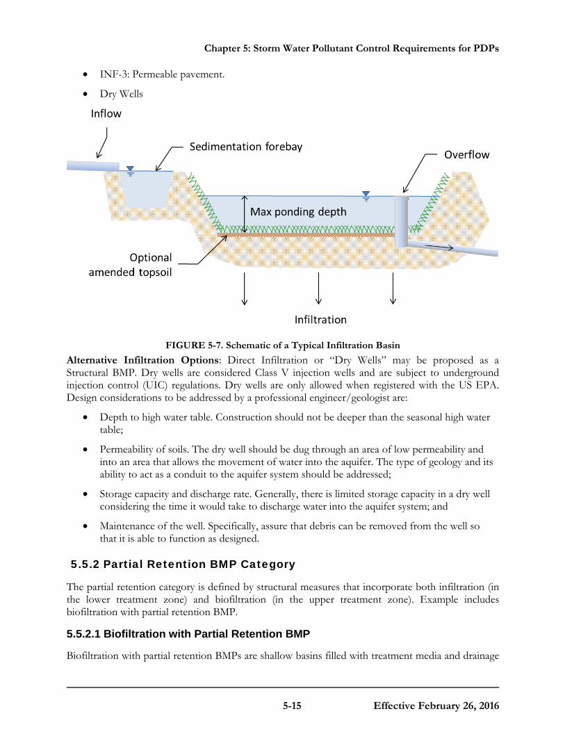
Chapter 5: Storm Water Pollutant Control Requirements for PDPs
5-15 Effective February 26, 2016
• INF-3: Permeable pavement.
• Dry Wells
FIGURE 5-7. Schematic of a Typical Infiltration Basin
Alternative Infiltration Options: Direct Infiltration or “Dry Wells” may be proposed as a Structural BMP. Dry wells are considered Class V injection wells and are subject to underground injection control (UIC) regulations. Dry wells are only allowed when registered with the US EPA. Design considerations to be addressed by a professional engineer/geologist are:
• Depth to high water table. Construction should not be deeper than the seasonal high water table;
• Permeability of soils. The dry well should be dug through an area of low permeability and into an area that allows the movement of water into the aquifer. The type of geology and its ability to act as a conduit to the aquifer system should be addressed;
• Storage capacity and discharge rate. Generally, there is limited storage capacity in a dry well considering the time it would take to discharge water into the aquifer system; and
• Maintenance of the well. Specifically, assure that debris can be removed from the well so that it is able to function as designed.
5.5.2 Partial Retention BMP Category
The partial retention category is defined by structural measures that incorporate both infiltration (in the lower treatment zone) and biofiltration (in the upper treatment zone). Example includes biofiltration with partial retention BMP.
5.5.2.1 Biofiltration with Partial Retention BMP
Biofiltration with partial retention BMPs are shallow basins filled with treatment media and drainage
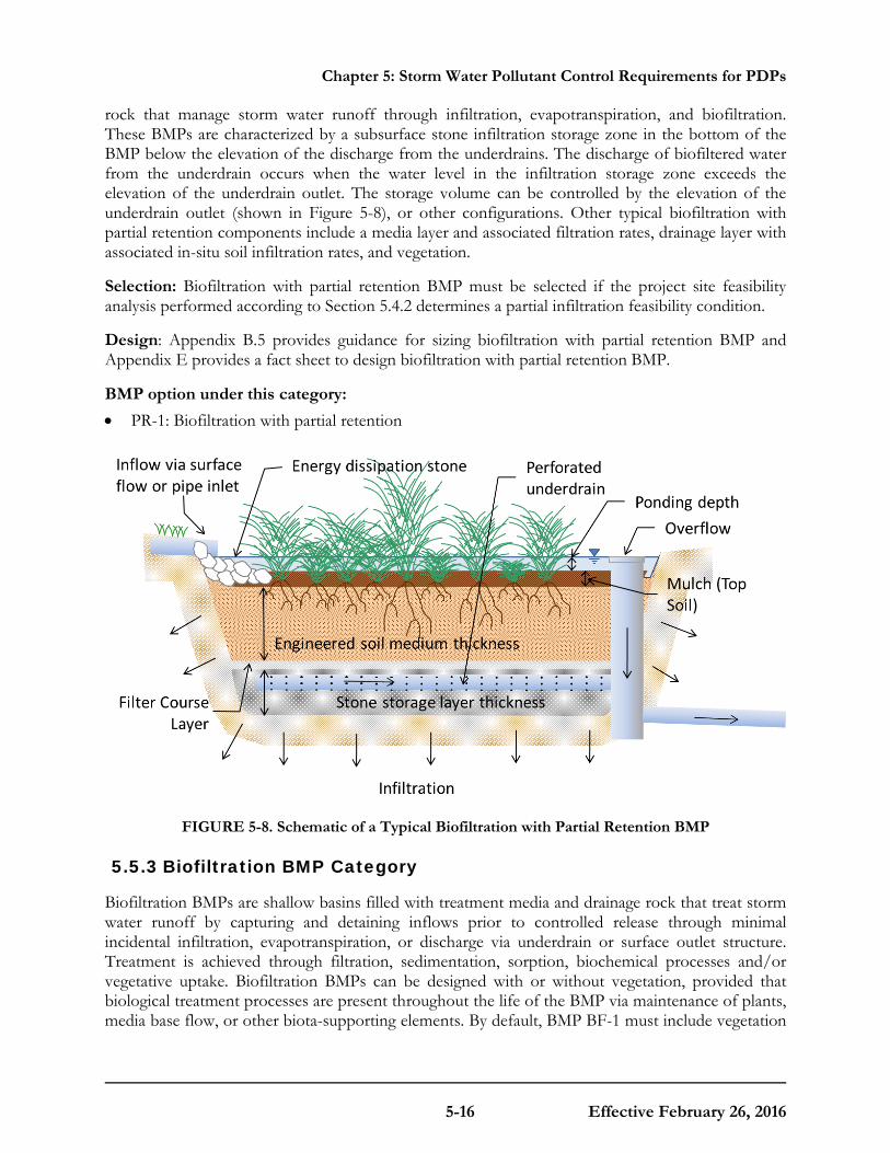
Chapter 5: Storm Water Pollutant Control Requirements for PDPs
5-16 Effective February 26, 2016
rock that manage storm water runoff through infiltration, evapotranspiration, and biofiltration. These BMPs are characterized by a subsurface stone infiltration storage zone in the bottom of the BMP below the elevation of the discharge from the underdrains. The discharge of biofiltered water from the underdrain occurs when the water level in the infiltration storage zone exceeds the elevation of the underdrain outlet. The storage volume can be controlled by the elevation of the underdrain outlet (shown in Figure 5-8), or other configurations. Other typical biofiltration with partial retention components include a media layer and associated filtration rates, drainage layer with associated in-situ soil infiltration rates, and vegetation.
Selection: Biofiltration with partial retention BMP must be selected if the project site feasibility analysis performed according to Section 5.4.2 determines a partial infiltration feasibility condition.
Design: Appendix B.5 provides guidance for sizing biofiltration with partial retention BMP and Appendix E provides a fact sheet to design biofiltration with partial retention BMP.
BMP option under this category: • PR-1: Biofiltration with partial retention
FIGURE 5-8. Schematic of a Typical Biofiltration with Partial Retention BMP
5.5.3 Biofiltration BMP Category
Biofiltration BMPs are shallow basins filled with treatment media and drainage rock that treat storm water runoff by capturing and detaining inflows prior to controlled release through minimal incidental infiltration, evapotranspiration, or discharge via underdrain or surface outlet structure. Treatment is achieved through filtration, sedimentation, sorption, biochemical processes and/or vegetative uptake. Biofiltration BMPs can be designed with or without vegetation, provided that biological treatment processes are present throughout the life of the BMP via maintenance of plants, media base flow, or other biota-supporting elements. By default, BMP BF-1 must include vegetation
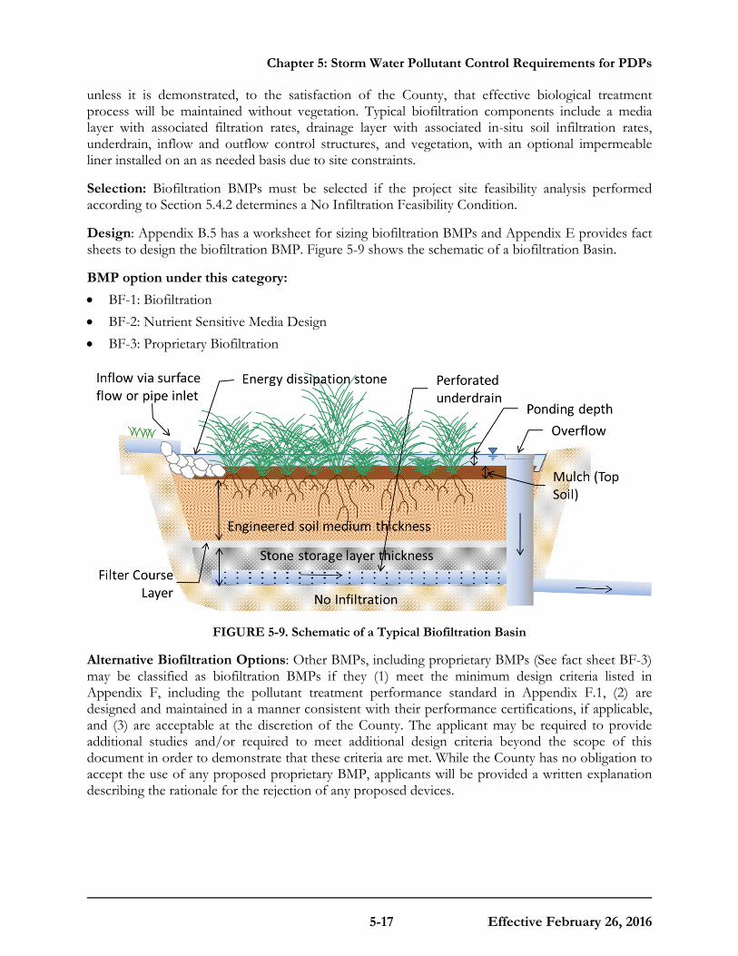
Chapter 5: Storm Water Pollutant Control Requirements for PDPs
5-17 Effective February 26, 2016
unless it is demonstrated, to the satisfaction of the County, that effective biological treatment process will be maintained without vegetation. Typical biofiltration components include a media layer with associated filtration rates, drainage layer with associated in-situ soil infiltration rates, underdrain, inflow and outflow control structures, and vegetation, with an optional impermeable liner installed on an as needed basis due to site constraints.
Selection: Biofiltration BMPs must be selected if the project site feasibility analysis performed according to Section 5.4.2 determines a No Infiltration Feasibility Condition.
Design: Appendix B.5 has a worksheet for sizing biofiltration BMPs and Appendix E provides fact sheets to design the biofiltration BMP. Figure 5-9 shows the schematic of a biofiltration Basin.
BMP option under this category: • BF-1: Biofiltration • BF-2: Nutrient Sensitive Media Design • BF-3: Proprietary Biofiltration
FIGURE 5-9. Schematic of a Typical Biofiltration Basin
Alternative Biofiltration Options: Other BMPs, including proprietary BMPs (See fact sheet BF-3) may be classified as biofiltration BMPs if they (1) meet the minimum design criteria listed in Appendix F, including the pollutant treatment performance standard in Appendix F.1, (2) are designed and maintained in a manner consistent with their performance certifications, if applicable, and (3) are acceptable at the discretion of the County. The applicant may be required to provide additional studies and/or required to meet additional design criteria beyond the scope of this document in order to demonstrate that these criteria are met. While the County has no obligation to accept the use of any proposed proprietary BMP, applicants will be provided a written explanation describing the rationale for the rejection of any proposed devices.

Chapter 5: Storm Water Pollutant Control Requirements for PDPs
5-18 Effective February 26, 2016
5.5.4 Flow-thru Treatment Control BMPs (for use with Offsite Alternative Compliance) Category
Flow-thru treatment control BMPs are structural, engineered facilities that are designed to remove pollutants from storm water runoff using treatment processes that do not incorporate significant biological methods.
Selection: Flow-thru treatment control BMPs must be selected based on the criteria in Appendix B.6. Flow-thru treatment control BMPs may only be implemented to satisfy PDP structural BMP performance requirements if an appropriate offsite alternative compliance project is also constructed to mitigate for the pollutant load in the portion of the DCV not retained or biofiltered onsite. The offsite alternative compliance program is an optional element that may be developed by each jurisdiction (See Section 1.8 and Appendix J).
Design: Appendix B.6 provides the methodology, required tables and worksheet for sizing flow-thru treatment control BMPs, and Appendix E provides fact sheets to design the flow-thru treatment control BMPs below. Figure 5-10 shows a schematic of a Vegetated Swale as an example of a flow-thru treatment control BMP.
BMP options under this category: • FT-1: Vegetated swales • FT-2: Media filters • FT-3: Sand filters • FT-4: Dry extended detention basin • FT-5: Proprietary flow-thru treatment control
FIGURE 5-10. Schematic of a Vegetated Swale
Use of Proprietary BMP Options: A proprietary BMP (see fact sheet FT-5) can be classified as a flow-thru treatment control BMP if (1) it is demonstrated to meet the flow-thru treatment performance criteria in Appendix B.6, (2) is designed and maintained in a manner consistent with its applicable performance certifications, and (3) is acceptable at the discretion of the County. The applicant may be required to provide additional studies and/or required to meet additional design criteria beyond the scope of this document in order to justify the use of a proprietary flow-thru treatment control BMP. While the County has no obligation to accept the use of any proposed
Check dam if bottom slope exceeds 2.5%
Outlet
Inlet
Flow Spreader
Energy Dissipater
Bottom Slope: 1.5- 6%
Side Slope: 3H:1V or milder

Chapter 5: Storm Water Pollutant Control Requirements for PDPs
5-19 Effective February 26, 2016
proprietary flow-thru BMP, applicants will be provided a written explanation describing the rationale for the rejection of any proposed devices.
5.5.5 Alternate BMPs
New and proprietary BMP technologies may be available that meet the performance standards in Chapter 2 but are not discussed in this Manual. Use of these alternate BMPs to comply with permit obligations is at the discretion of the County. Alternate BMPs must meet the standards for biofiltration BMPs or flow-thru BMPs (depending on how they are used), as described in Appendix F and Appendix B.6, respectively.
5.6 Documenting Storm Water Pollutant Control BMP Compliance when Hydromodification Management Applies The steps and guidance presented in Chapter 5 apply to all PDPs for demonstrating conformance with storm water pollutant control requirements regardless of whether hydromodification management applies. However, when hydromodification management applies, the approach for project design may be different. The following process can be used to document compliance with storm water pollutant control BMPs in cases when hydromodification management also applies:
1. Develop a combined BMP or treatment train (BMPs constructed in series) based on both storm water pollutant control and hydromodification management requirements. Appendix E provides specific examples of how storm water pollutant control BMPs can be configured to also address hydromodification management.
2. Dedicate a portion of the combined BMP or treatment train as the portion that is intended to comply with storm water pollutant control requirements.
3. Follow all of the steps in this chapter related to demonstrating that the dedicated portion of the BMP or treatment train meets the applicable storm water pollutant control criteria.
4. Check BMP design criteria in Appendix E and F to ensure that the hydromodification management design features (additional footprint, additional depth, modified outlet structure, lower discharge rates, etc.) do not compromise the treatment function of the BMP.
5. On project plans and in the maintenance plan, clearly denote the portion of the BMP that serves the storm water pollutant control function.
Alternative approaches that meet both the storm water pollutant control and hydromodification management requirements may be acceptable at the discretion of the County and must be documented in the SWQMP. Also refer to Section 6.3.6 for additional guidance.

Chapter 5: Storm Water Pollutant Control Requirements for PDPs
5-20 Effective February 26, 2016
This page was intentionally left blank.
C O U N T Y O F S A N D I E G O B M P D E S I G N M A N U A L
6-1 Effective February 26, 2016
Chapter
6 Hydromodification Management Requirements for PDPs The purpose of hydromodification management requirements for PDPs is to minimize the potential of storm water discharges from the MS4 from causing altered flow regimes and excessive downstream erosion in receiving waters. Hydromodification management implementation for PDPs includes two components: protection of critical coarse sediment yield areas and flow control for post-project runoff from the project site. For PDPs subject to hydromodification management requirements, this Chapter provides guidance to meet the performance standards for the two components of hydromodification management.
The civil engineer preparing the hydromodification management study for a project will find within this Chapter and Appendix G of this Manual, along with watershed-specific information in the WMAA, all necessary information to meet the MS4 Permit standards. Should unique project circumstances require an understanding beyond what is provided in this Manual, then consult the March 2011 Final HMP, which documents the historical development of the hydromodification management requirements.
Guidance for flow control of post-project runoff is based on the March 2011 Final HMP, with modifications in this Manual based on updated requirements in the MS4 Permit. The March 2011 Final HMP was prepared based on the 2007 MS4 Permit, not the MS4 Permit that drives this Manual. In instances where there are changes to hydromodification management criteria or procedures based on the MS4 Permit, the criteria and procedures presented in this Manual supersede the March 2011 Final HMP.
Protection of critical coarse sediment yield areas is a new requirement of the MS4 Permit and is not covered in the March 2011 Final HMP. The standards and management practices for protection of critical coarse sediment yield areas are addressed below and in Appendix H.
6.1 Hydromodification Management Applicability and Exemptions As noted in Chapter 1, Section 1.6 a project may be exempt from hydromodification management requirements if it meets any one of the following conditions:

Chapter 6: Hydromodification Management Requirements for PDPs
6-2 Effective February 26, 2016
• The project is not a PDP;
• The proposed project will discharge runoff directly to existing underground storm drains discharging directly to water storage reservoirs, lakes, enclosed embayments, or the Pacific Ocean;
• The proposed project will discharge runoff directly to conveyance channels whose bed and bank are concrete lined all the way from the point of discharge to water storage reservoirs, lakes, enclosed embayments, or the Pacific Ocean; or
• The proposed project will discharge runoff directly to an area identified by the County as appropriate for an exemption by the WMAA8 for the watershed in which the project resides9.
The above criteria reflect the latest list of exemptions that are allowed under the MS4 Permit10 and therefore supersede criteria found in earlier publications.
Exempt water storage reservoirs and lakes in San Diego County are shown in the WMAA for each watershed.
Detailed criteria for determining a "direct discharge" to an exempt water body are presented in Section 1.6.
6.2 Protection of Critical Coarse Sediment Yield Areas When hydromodification management requirements are applicable, the applicant must determine if the project will impact any areas that are determined to be critical coarse sediment yield areas (CCSYAs). A CCSYA is an area that has been identified as an active or potential source of coarse sediment to downstream channel reaches. The process for demonstrating that the PDP does not impact CCSYAs is illustrated in Figure 6-1 below, and supplemented with detailed methodologies presented in Appendix H of this manual. PDPs complying with this MS4 Permit requirement are not subject to the provisions of the Total Maximum Daily Load for Sediment in Los Peñasquitos Lagoon, post construction. However, PDPs may be subject to Total Maximum Daily Load requirements during construction.
8 The San Diego County Regional WMAA report can be found on the Project Clean Water website here:
http://www.projectcleanwater.org/
9 Applicants electing to perform an analysis a project from hydromodification management requirements shall use the methodology presented in Attachment E of the Regional Watershed Management Area Analysis.
10 Any proposed changes to hydromodification management exemption mapping must be approved by the RWQCB through the WQIP Annual Update process.

Chapter 6: Hydromodification Management Requirements for PDPs
6-3 Effective February 26, 2016
FIGURE 6-1. Pathways to meet CCSYA requirements
Description of Steps:
Step 1. Applicants must identify CCSYAs located onsite and/or upstream of the project’s property boundary per the guidance presented in Appendix H.1. If no CCSYAs are identified in this step, no further consideration of critical coarse sediment supply is necessary.
Step 2. Applicants should avoid impacts to onsite CCSYAs through effective site design techniques discussed in Appendix H.2.
Step 3. Applicants should bypass bed sediment from onsite and/or upstream CCSYAs to downstream receiving waters per guidance presented in Appendix H.3.
Step 4. When impacts to CCSYAs are not avoided or bypassed through the site, the applicant must demonstrate that the project generates no net impact to the receiving water per guidance presented in Appendix H.4
6.3 Flow Control for Hydromodification Management PDPs subject to hydromodification management requirements must provide flow control for post-project runoff to meet the flow control performance standard.
This is typically accomplished using structural BMPs that may include any combination of infiltration basins; bioretention, biofiltration with partial retention, or biofiltration basins; or detention basins. This Section will discuss design of flow control measures for hydromodification management. It is intended to be used following the source control and site design processes described in Chapter 4 and the storm water pollutant control design process described in Chapter 5.
The flow control performance standard is as follows:

Chapter 6: Hydromodification Management Requirements for PDPs
6-4 Effective February 26, 2016
1 For flow rates ranging from 10 percent, 30 percent or 50 percent of the pre-development 2-year runoff event (0.1Q2, 0.3Q2, or 0.5Q2) to the pre-development 10-year runoff event (Q10), the post-project discharge rates and durations must not exceed the pre-development rates and durations by more than 10 percent. The specific lower flow threshold will depend on the erosion susceptibility of the receiving stream for the project site (see Section 6.3.4).
In this context, Q2 and Q10 refer to flow rates determined based on either continuous simulation hydrologic modeling or an approved regression equation. The range from a fraction of Q2 to Q10 represents the range of geomorphically significant flows for hydromodification management in San Diego. The upper bound of the range of flows to control is pre-development Q10 for all projects. The lower bound of the range of flows to control, or "lower flow threshold" is a fraction of pre-development Q2 that is based on the erosion susceptibility of the stream and depends on the specific natural system (stream) that a project will discharge to. Tools have been developed in the March 2011 Final HMP for assessing the erosion susceptibility of the stream (see Section 6.3.4 below for further discussion of the lower flow threshold).
When selecting the type of structural BMP to be used for flow control, consider the types of structural BMPs that will be utilized onsite for pollutant control.
Both storm water pollutant control and flow control for hydromodification management can be achieved within the same structural BMPs. For example, a full infiltration BMP that infiltrates the DCV for pollutant control could include additional storage volume above or below ground to provide either additional infiltration of storm water or control of outflow for hydromodification management. If possible, the structural BMPs for pollutant control should be modified to meet flow control performance standards in addition to the pollutant control performance standards. See Section 6.3.6 for further discussion of integrating structural BMPs for pollutant control and flow control.
6.3.1 Point(s) of Compliance
For PDPs subject to hydromodification management requirements, the flow control performance standard must be met for each natural or un-lined channel that will receive runoff from the project.
This may require multiple structural BMPs within the project site if the project site discharges to multiple discrete outfalls. When runoff is discharged to multiple natural or un-lined channels within a project site, each natural or un-lined channel must be considered separately and points of compliance (POCs) for flow control must be provided for each natural or un-lined channel, including situations where the channels will confluence before leaving the project boundary. When runoff from the project site does not meet a natural or un-lined channel onsite, instead traveling some distance downstream of the project in storm drain systems or lined channels prior to discharge to natural or un-lined channels, the POC(s) for flow control analysis must be placed at the project boundary (i.e., comparing the pre-development and post-project flows from the project area only, not analyzing the total watershed draining to the offsite POC), unless the project is draining to and accommodated by an approved master planned or regional flow control BMP.
For individual projects draining to approved master planned or regional flow control BMPs, the POC for flow control analysis may be offsite of the specific project application.
In these instances, the individual project draining to a master planned or regional flow control BMP
Chapter 6: Hydromodification Management Requirements for PDPs
6-5 Effective February 26, 2016
must reference the approved design documents for the BMP, and must demonstrate that either (a) the individual project design is consistent with assumptions made for imperviousness and features of the project area when the master planned or regional BMP was designed, or (b) the master planned or regional BMP still meets performance standards when the actual proposed imperviousness and features of the project area are considered.
6.3.2 Offsite Area Restrictions
Runoff from offsite undeveloped areas should be routed around structural BMPs for flow control whenever feasible. Methods to route flows around structural BMPs include designing the site to avoid natural drainage courses, or using parallel storm drain systems. If geometric constraints prohibit the rerouting of flows from undeveloped areas around a structural BMP, a detailed description of the constraints must be submitted to the County.
Structural BMPs for flow control must be designed to avoid trapping sediment from natural areas regardless of whether the natural areas are critical coarse sediment yield areas or not. Reduction in coarse sediment supply contributes to downstream channel instability. Capture and removal of natural sediment from the downstream watercourse can create "hungry water" conditions and the increased potential for downstream erosion. Additionally, coarse or fine sediment from natural areas can quickly fill the available storage volume in the structural BMP or clog a small flow control outlet, which can cause the structural BMP to overflow during events that should have been controlled, and will require frequent maintenance. Failure to prevent clogging of the principal control orifice defeats the purpose of a flow control BMP, since basin inflows would simply overtop the control structure and flow un-attenuated downstream, potentially worsening downstream erosion.
6.3.3 Requirement to Control to Pre-Development (Not Pre-Project) Condition
The MS4 Permit requires that post-project runoff must be controlled to match pre-development runoff conditions, not pre-project conditions, for the range of flow rates to be controlled.
Pre-development runoff conditions are defined in the MS4 Permit as "approximate flow rates and durations that exist or existed onsite before land development occurs."
• Redevelopment PDPs: Use available maps or development plans that depict the topography of the site prior to development, otherwise use existing onsite grades if historic topography is not available. Assume the infiltration characteristics of the underlying soil. Use available information pertaining to existing underlying soil type such as soil maps published by the Natural Resource Conservation Service (NRCS). Do not use runoff parameters for concrete or asphalt to estimate pre-development runoff conditions.
• New development PDPs: The pre-development condition typically equates to runoff conditions immediately before project construction. However if a natural compacted soils condition exists, infiltration characteristics for that runoff condition may be assumed (refer to Appendix G, Table G.1.4 for allowable adjustments).

Chapter 6: Hydromodification Management Requirements for PDPs
6-6 Effective February 26, 2016
When it is necessary for runoff from offsite impervious area (not a part of the project) to co-mingle with project site runoff and be conveyed through a project's structural flow control BMP, the offsite impervious area may be modeled as impervious in both the pre- and post- condition models. A project is not required to provide flow control for storm water from offsite. This also means that for redevelopment projects not subject to the 50% rule (i.e., redevelopment projects that result in the creation or replacement of impervious surface in an amount of less than 50% of the area of impervious surface of the previously existing development), comingled runoff from undisturbed portions of the previously existing development (i.e., areas that are not a part of the project) will not require flow control. Flow control facilities for comingled offsite and onsite runoff would be designed to process the total volume of the comingled runoff through the facility, but would provide mitigation for the excess runoff (difference of developed to pre-developed condition) based on onsite impervious areas only. The project applicant must clearly explain why it was not feasible or practical to provide a bypass system for storm water from offsite. The County may request that the project applicant provide a supplemental analysis of onsite runoff only (i.e., supplemental model of the project area only).
6.3.4 Determining the Low Flow Threshold for Hydromodification Flow Control
The range of flows to control for hydromodification management depends on the erosion susceptibility of the receiving stream.
The range of flows to control is either:
• 0.1Q2 to Q10 for projects discharging to streams with high susceptibility to erosion (and this is the default range of flows to control when a stream susceptibility study has not been prepared),
• 0.3Q2 to Q10 for projects discharging to streams with medium susceptibility to erosion as determined by a stream susceptibility study approved by the County, or
• 0.5Q2 to Q10 for projects discharging to streams with low susceptibility to erosion as determined by a stream susceptibility study approved by the County.
The project applicant may opt to design to the default low flow threshold of 0.1Q2, or provide assessment of the receiving stream ("channel screening" a.k.a. "geomorphic assessment"), which may result in a higher low flow threshold of 0.3Q2 or 0.5Q2 for project hydromodification management.
Use of a higher low flow threshold of 0.3Q2 or 0.5Q2 must be supported by a channel screening report. Channel screening is based on a tool developed by the Southern California Coastal Water Research Project (SCCWRP), documented in SCCWRP's Technical Report 606 dated March 2010, "Hydromodification Screening Tools: Field Manual for Assessing Channel Susceptibility." The SCCWRP channel screening tool considers channel conditions including channel braiding, mass wasting, and proximity to the erosion threshold. SCCWRP's Technical Report 606 is included in Appendix B of the March 2011 Final HMP, and can also be accessed through SCCWRP's website. The result of applying the channel screening tool will be classification of high, medium, or low susceptibility to erosion, corresponding to low flow thresholds of 0.1Q2, 0.3Q2, and 0.5Q2, respectively, for the receiving stream. Note that the County may require that the channel screening study has been completed within a specific time frame prior to their review, and/or may apply a sunset date to their approval of a channel screening study.
Chapter 6: Hydromodification Management Requirements for PDPs
6-7 Effective February 26, 2016
The receiving stream is the location where runoff from the project is discharged to natural or un-lined channels.
The receiving stream may be onsite or offsite. The POC for channel screening is the point where runoff initially meets an un-lined or natural channel, regardless of whether the POC for flow control facility sizing is at or within the project boundary or is offsite. A project may have a different POC for channel screening vs. POC for flow control facility sizing if runoff from the project site is conveyed in hardened systems from the project site to the un-lined or natural channel. The erosion susceptibility of the receiving stream must be evaluated at the POC for channel screening, and for an additional distance known as the domain of analysis, defined in SCCWRP's Technical Report 606.
6.3.5 Designing a Flow Control Facility
Flow control facilities for hydromodification management must be designed based on continuous simulation hydrologic modeling, which may be accomplished as a project-specific continuous simulation model, or by using sizing factors previously developed for this purpose in the March 2011 Final HMP.
Continuous simulation hydrologic modeling uses an extended time series of recorded precipitation data and evapotranspiration data as input and generates hydrologic output, such as surface runoff, groundwater recharge, and evapotranspiration, for each model time step. Using the continuous flow output, peak flow frequency and duration statistics can be generated for the pre-development and post-project conditions for the purpose of matching pre-development hydrologic conditions in the range of geomorphically significant flow rates. Peak flow frequency statistics estimate how often flow rates will exceed a given threshold. Flow duration statistics determine how often a particular flow rate is exceeded. To determine if a flow control facility meets hydromodification management performance standards, peak flow frequency and flow duration curves must be generated and compared for pre-development and post-project conditions.
Flow control facilities may be designed using either sizing factors presented in Appendix B, or using project-specific continuous simulation modeling. The sizing factors were developed based on unit-area continuous simulation models. This means the continuous simulation hydrologic modeling has already been done and the project applicant needs only to apply the sizing factors to the project's effective impervious area to size a facility that meets flow control performance standards. The sizing factor method is intended for simple studies that do not include diversion, do not include significant offsite area draining through the project from upstream, and do not include offsite area downstream of the project area. Use of the sizing factors is limited to the specific structural BMPs for which sizing factors were prepared. Project-specific continuous simulation modeling offers the most flexibility in the design, but requires the project applicant to prepare and submit a complete continuous simulation hydrologic model for review.
6.3.5.1 Sizing Factor Method
A project applicant may use sizing factors that were created to facilitate sizing of certain specific BMPs for hydromodification management.
Unit runoff ratios for determination of pre-development Q2 and sizing factors for certain specific structural BMPs were previously developed based on continuous simulation hydrologic modeling of hypothetical unit watersheds. Details and descriptions for the sizing factors and specific BMPs are presented in the "San Diego BMP Sizing Calculator Methodology," dated January 2012, prepared by

Chapter 6: Hydromodification Management Requirements for PDPs
6-8 Effective February 26, 2016
Brown and Caldwell (herein "BMP Sizing Calculator Methodology"). Although the sizing factors were developed under the 2007 MS4 Permit, the unit runoff ratios and some sizing factors developed for flow control facility sizing may still be applied at the discretion of County staff. Users should note that due to the MS4 Permit requirement to control flow rates to pre-development condition instead of pre-project condition, unit runoff ratios for "impervious" soil cover categories from Table 1-6 of the BMP Sizing Calculator Methodology must not be used when determining pre-development Q2. Sizing factors are to be applied to the effective impervious area draining to the facility. Calculations may be prepared using either the BMP Sizing Spreadsheet that was developed by the County of San Diego and is available on the Project Clean Water website, or using hand calculations.
This is an older method that generally produces conservative results. If an applicant elects to use this methodology please refer to Appendix G.2.
6.3.5.2 Project-Specific Continuous Simulation Modeling
A project applicant may prepare a project-specific continuous simulation model to demonstrate compliance with hydromodification management performance standards.
This option offers the most flexibility in the design. In this case, the project applicant must prepare continuous simulation hydrologic models for pre-development and post-project conditions, and compare the pre-development and post-project (with hydromodification flow control BMPs) runoff rates and durations until compliance with the flow control performance standards is demonstrated. The project applicant will be required to quantify the long term pre-development and post-project runoff response from the site and establish runoff routing and stage-storage-discharge relationships for the planned flow control BMPs. There are several available hydrologic models that can perform continuous simulation analyses. Refer to Appendix G.1 of this Manual for guidance for continuous simulation hydrologic modeling.
6.3.6 Integrating HMP Flow Control Measures with Pollutant Control BMPs
Both storm water pollutant control and flow control for hydromodification management can be achieved within the same structural BMP(s) or by a series of structural BMP(s).
The design process should start with an assessment of the controlling design factor. Then the typical design process for an integrated structural BMP or series of BMPs to meet two separate performance standards at once involves (1) initiating the design based on the performance standard that is expected to require the largest volume of storm water to be retained, (2) checking whether the initial design incidentally meets the second performance standard, and (3) adjusting the design as necessary until it can be demonstrated that both performance standards are met. The following are recommended for initiating the design process: • Full infiltration condition: Retention for pollutant control performance standard is the
controlling design factor. For a system that is based on full retention for storm water pollutant control, first design an initial retention area to meet storm water pollutant control standards for retention. Then check whether the facility meets flow control performance standards. If the initial retention facility does not meet flow control performance standards: increase the volume of the facility, increasing retention if feasible or employing outflow control for runoff to be discharged from the facility; as needed to meet the flow control performance standards.
Chapter 6: Hydromodification Management Requirements for PDPs
6-9 Effective February 26, 2016
• Partial infiltration condition: Retention for pollutant control performance standard is the controlling design factor. For a system that is based on partial retention for storm water pollutant control, first design the retention area to maximize retention as feasible. Then design an additional runoff storage area with outflow control for runoff to be discharged from the facility; as needed to meet the flow control performance standards. Then address pollutant control needs for the portion of the storm water pollutant control DCV that could not be retained onsite.
• No infiltration condition: Flow control for hydromodification management standard is the controlling design factor. For a system that is based on biofiltration with no infiltration for storm water pollutant control, first design the facility to meet flow control performance standards. Then check whether the facility meets biofiltration design standards for storm water pollutant control. If the flow control biofiltration facility does not meet performance standards for storm water pollutant control by biofiltration, increase the volume of the biofiltration facility as needed to meet pollutant control performance standards. Or identify other methods to address pollutant control needs for the portion of the storm water pollutant control DCV that could not be processed with biofiltration onsite.
When an integrated structural BMP or series of BMPs is used for both storm water pollutant control and flow control for hydromodification management, separate calculations are required to demonstrate that pollutant control performance standards and hydromodification management standards are met.
When an integrated structural BMP or series of BMPs is proposed to meet the storm water pollutant control and flow control for hydromodification management obligations, the applicant must either:
• Perform separate calculations to show that both hydromodification management and pollutant control performance standards are met independently by using guidance from Appendices B and G. Calculations performed must be documented in the SQWMP. or
• Develop an integrated design that meets the separate performance standards presented in Chapter 2 for both hydromodification management and pollutant control. In this option the BMP requirements to meet the pollutant control performance standard are optimized to account for the BMP storage provided for flow control, and vice versa. Calculations performed to develop an integrated design must be documented in the SQWMP. Project approval when this option is selected is at the discretion of the County.
Appendix B.5.2 provides a methodology to optimize the footprint of the downstream biofiltration BMP that is required to meet the pollutant control performance standard, when there is an upstream hydromodification flow control BMP (e.g. cistern, vault, etc.).
6.3.7 Drawdown Time
The maximum recommended drawdown time for hydromodification management facilities is 96 hours based on Section 6.4.6 of the March 2011 Final HMP.
This is additionally supported by instruction from the County of San Diego Department of Environmental Health for mitigation of potential vector breeding issues and the subsequent risk to human health. This standard applies to, but is not limited to, detention basins, underground storage vaults, and the above-ground storage portion of LID facilities. When this standard cannot be met
Chapter 6: Hydromodification Management Requirements for PDPs
6-10 Effective February 26, 2016
due to large stored runoff volumes with limited maximum release rates, a vector management plan may be an acceptable solution if approved by the County.
In cases where a Vector Management Plan is necessary, it must be incorporated into the SWQMP as an attachment. A Vector Management Plan will only be accepted after it has been approved by the County of San Diego Department of Environmental Health. The information included in the plan will vary based on the nature, extent and variety of potential vector sources. It is recommended that preparers consult with the Department of Environmental Health Vector Control Program for technical guidance. Plans should include the following information at a minimum:
• Project identification information;
• A description of the project, purpose of the report, and existing environmental conditions;
• A description of the management practices that will be employed to minimize vector breeding sources and any associated employee education required to run facilities and operations;
• A discussion of long term maintenance requirements;
• A summary of mitigation measures;
• References; and
• A list of persons and organizations contacted (project proponents are expected to obtain review and concurrence of proposed management practices from Department of Environmental Health Vector control program staff prior to submission).
The property owner and applicant must include and sign the following statement: “The measures identified herein are considered part of the proposed project design and will be carried out as part of project implementation. I understand the breeding of mosquitoes in unlawful under the State of California Health and Safety Code Section 2060-2067. I will permit the Vector Surveillance and Control program to place adult mosquito monitors and to enforce this document as needed.”
Refer to the sources below for additional guidance:
Report Guidance- http://www.sandiegocounty.gov/content/dam/sdc/pds/docs/vector_report_formats.pdf
Department of Environmental Health Vector Control Program Department of Environmental Health (Phone number: [858] 694-2888) - http://www.sandiegocounty.gov/deh/pests/vector_disease.html
It should be noted that other design factors may influence the required drawdown when hydromodification management BMPs are integrated with storm water pollutant control BMPs. Since hydromodification flow control BMPs are designed based on continuous simulation modeling, which is based on a continuous rainfall record and analyzes a continuous inflow and outflow of the BMPs, inter-event drawdown time and availability of the BMP for subsequent event inflow has been accounted for in the sizing. Therefore, drawdown recommendations for hydromodification management are based on public safety, not availability of the BMP for the next inflow event. Storm water pollutant control BMPs are designed on a single-event basis for a DCV (the 85th percentile storm event). Some of the design standards presented in Chapter 5 or Appendix B require that the

Chapter 6: Hydromodification Management Requirements for PDPs
6-11 Effective February 26, 2016
pollutant control portion of the BMP drain within a specific time frame to ensure the pollutant control portion of the BMP is available for subsequent storm events. When hydromodification management BMPs are integrated with storm water pollutant control BMPs, the designer must evaluate drawdown time based on both standards.
6.4 In-Stream Rehabilitation An alternative to onsite flow control for post-project runoff may be in-stream rehabilitation.
Project applicants may be allowed to implement an in-stream rehabilitation project in lieu of implementing onsite flow control BMPs. Refer to Appendix J for additional information.

Chapter 6: Hydromodification Management Requirements for PDPs
6-12 Effective February 26, 2016
This page was intentionally left blank.
M O D E L B M P D E S I G N M A N U A L
7-1 Effective February 26, 2016
Chapter
7 Long Term Operation & Maintenance Permanent structural BMPs require on-going inspection and maintenance into perpetuity to preserve the intended pollution control and/or flow control performance.
This Chapter addresses procedural requirements for implementation of long term maintenance and the typical maintenance requirements of structural BMPs presented in the manual. Specific requirements for Maintenance Plan reports will be discussed in Chapter 8 with the Submittal Requirements.
7.1 Need for Permanent Inspection and Maintenance
7.1.1 MS4 Permit Requirements
The MS4 Permit requires that each Copermittee implement a program that requires and confirms structural BMPs on all PDPs are designed, constructed, and maintained to remove pollutants in storm water to the MEP.
Routine inspection and maintenance of BMPs will preserve the design and MS4 Permit objective to remove pollutants in storm water to the MEP. The MS4 Permit requirement specifically applies to PDP structural BMPs. However, source control BMPs and site design / LID BMPs within a PDP are components in the storm water management scheme that determine the amount of runoff to be treated by structural BMPs; and when source control, site design, or LID BMPs are not maintained, this can lead to clogging or failure of structural BMPs due to greater delivery of runoff and pollutants than intended.
7.1.2 Practical Considerations
Why do permanent structural BMPs require on-going inspection and maintenance into perpetuity?
By design, structural BMPs will trap pollutants transported by storm water. Structural BMPs are subject to deposition of solids such as sediment, trash, and other debris. Some structural BMPs are also subject to growth of vegetation, either by design (e.g. biofiltration) or incidentally. The pollutants and any overgrown vegetation must be removed on a periodic basis for the life of the BMP to maintain the capacity of the structural BMP to process storm water and capture pollutants from every storm event. Structural BMP components are also subject to clogging from trapped pollutants and growth of vegetation. Clogged BMPs can result in flooding, standing water and
Chapter 7: Long Term Operation and Maintenance
7-2 Effective February 26, 2016
mosquito breeding habitat. Maintenance is critical to ensure the ongoing drainage of the facility. All components of the BMP must be maintained, including both the surface and any sub-surface components.
Vegetated structural BMPs, including vegetated infiltration or partial infiltration BMPs, and above-ground detention basins, also require routine maintenance so that they don't inadvertently become wetlands, waters of the state, or sensitive species habitat under the jurisdiction of the United States Army Corps of Engineers, SDRWQCB, California Department of Fish and Wildlife, or the United States Fish and Wildlife Service. A structural BMP that is constructed in the vicinity of, or connected to, an existing jurisdictional water or wetland could inadvertently result in creation of expanded waters or wetlands. As such, vegetated structural BMPs have the potential to come under the jurisdiction of one or more of the above-mentioned resource agencies. This could result in the need for specific resource agency permits and costly mitigation to perform maintenance of the structural BMP. Along with proper placement of a structural BMP, routine maintenance is key to preventing this scenario.
7.2 Summary of Steps to Maintenance Agreement Ownership and maintenance responsibility for structural BMPs should be discussed at the beginning of project planning, typically at the pre-application meeting with the planning and zoning agency.
Experience has shown provisions to finance and implement maintenance of BMPs can be a major stumbling block to project approval, particularly for small residential subdivisions. Project owners must be aware of their responsibilities regarding storm water BMP maintenance and need to be familiar with the contents of the Maintenance Plan prepared for the project. Chapter 8 provides the guidelines for preparation of a site specific Maintenance Plan. A maintenance mechanism must be determined prior to the issuance of any construction, grading, building permit, site development permit, or any other applicable permit. Table 7-1 describes the typical steps and schedule for establishing a plan and mechanism to ensure on-going maintenance of structural BMPs.
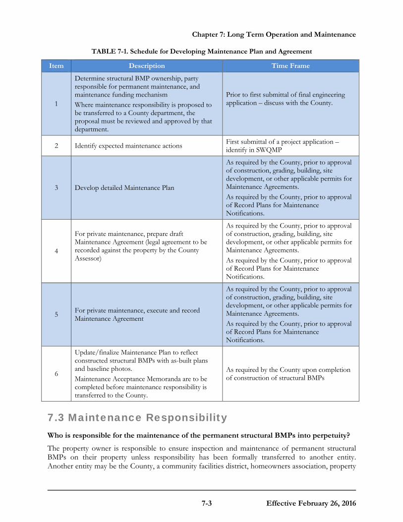
Chapter 7: Long Term Operation and Maintenance
7-3 Effective February 26, 2016
TABLE 7-1. Schedule for Developing Maintenance Plan and Agreement
Item Description Time Frame
1
Determine structural BMP ownership, party responsible for permanent maintenance, and maintenance funding mechanism Where maintenance responsibility is proposed to be transferred to a County department, the proposal must be reviewed and approved by that department.
Prior to first submittal of final engineering application – discuss with the County.
2 Identify expected maintenance actions First submittal of a project application – identify in SWQMP
3 Develop detailed Maintenance Plan
As required by the County, prior to approval of construction, grading, building, site development, or other applicable permits for Maintenance Agreements. As required by the County, prior to approval of Record Plans for Maintenance Notifications.
4
For private maintenance, prepare draft Maintenance Agreement (legal agreement to be recorded against the property by the County Assessor)
As required by the County, prior to approval of construction, grading, building, site development, or other applicable permits for Maintenance Agreements. As required by the County, prior to approval of Record Plans for Maintenance Notifications.
5 For private maintenance, execute and record Maintenance Agreement
As required by the County, prior to approval of construction, grading, building, site development, or other applicable permits for Maintenance Agreements. As required by the County, prior to approval of Record Plans for Maintenance Notifications.
6
Update/finalize Maintenance Plan to reflect constructed structural BMPs with as-built plans and baseline photos. Maintenance Acceptance Memoranda are to be completed before maintenance responsibility is transferred to the County.
As required by the County upon completion of construction of structural BMPs
7.3 Maintenance Responsibility Who is responsible for the maintenance of the permanent structural BMPs into perpetuity?
The property owner is responsible to ensure inspection and maintenance of permanent structural BMPs on their property unless responsibility has been formally transferred to another entity. Another entity may be the County, a community facilities district, homeowners association, property
Chapter 7: Long Term Operation and Maintenance
7-4 Effective February 26, 2016
owners association, or other special district. When property ownership changes (i.e. the property is sold or otherwise transferred to a new owner), maintenance responsibility also transfers to the new owner, typically by transfer of a maintenance agreement recorded against the property by the County Assessor. For structural BMPs that will be transferred to the County, a community facilities district, homeowners association, property owners association, or other special district, there may be an interim period during which the property owner is responsible until maintenance responsibility is formally transferred.
From the time that the structural BMP is constructed and activated (i.e. it is operating and processing storm water from storm events), it requires inspection and maintenance to ensure it continues to function as designed. Because of this, the MS4 Permit requires that each jurisdiction must "require the project applicant to submit proof of the mechanism under which ongoing long-term maintenance of all structural BMPs will be conducted." The County has different allowable maintenance mechanisms (e.g. privately funded or publicly funded maintenance) and/or requirements for proof of the maintenance mechanism (e.g. maintenance agreements). Requirements for proof of the maintenance mechanism are required for publicly maintained structural BMPs as well (e.g., Maintenance Acceptance Memorandum, Community Facility District).
Applicants must propose for County determination the appropriate maintenance mechanism for selected BMPs. The BMPs should fit into one of the following categories.
7.3.1 Category One
Structural BMPs that are minor in nature, have minimal maintenance responsibilities, and are typical for residential land uses. The proposed BMPs inherently "take care of themselves", or property owners can naturally be expected to do so as an incident of taking care of their property. The owner will perform ongoing maintenance with County’s reduced oversight. A “Maintenance Notification” that records with the property is required for all Category 1 BMPs. At a minimum, the responsible party provides annual documentation to the County verifying that the BMPs are maintained and functioning properly.
Structural BMPs that may be eligible for this classification will have a single owner; the maintenance will be routine, such as landscaping and the drainage management area will be small, typically draining a single lot.
Category 1 Mechanisms to Assure Maintenance:
1. Watershed Protection Ordinance Requirement: WPO Section 67.812 requires ongoing maintenance of BMPs. In the event that the mechanisms below prove ineffective, or in addition to enforcing those mechanisms, civil action, criminal action or administrative citation could also be pursued for violations of the ordinance.
2. Public Nuisance Abatement: Under the WPO failure to maintain a BMP would constitute a public nuisance, which may be abated under the Uniform Public Nuisance Abatement Procedure. This provides an enforcement mechanism additional to the above, and would allow costs of maintenance to be billed to the owner, a lien placed on the property, and the tax collection process to be used.

Chapter 7: Long Term Operation and Maintenance
7-5 Effective February 26, 2016
3. Notice to Purchasers: Section 67.812(e) of the WPO requires developers to provide clear written notification to persons acquiring land upon which a BMP is located, or others assuming a BMP maintenance obligation, of the maintenance duty.
4. Conditions in Ongoing Land Use Permits: For those applications (listed in WPO Section 67.803(c)) upon whose approval ongoing conditions may be imposed, a condition will be added which requires the owner of the land upon which the stormwater facility is located to maintain that facility in accordance with the requirements specified in the maintenance plan (Attachment F in the Major SWMP). Failure to perform maintenance may then be addressed as a violation of the permit, under the ordinance governing that permit process.
5. Subdivision Public Report: Tentative Map and Tentative Parcel Map approvals will be conditioned to require that, prior to approval of a Final or Parcel Map, the subdivider must provide evidence to the County that the subdivider has requested the California Department of Real Estate to include in the public report to be issued for the sales of lots within the subdivision, a notification regarding the maintenance requirement. (The requirement for this condition would not be applicable to specific subdivisions which are exempt from regulation under the Subdivided Lands Act, or for which no public report will be issued.)
6. BMP Maintenance Notification: WPO Section 67.812(f) requires that an agreement be entered into with the County, which will function in three ways:
a. It will notify new landowners of the presence and location of the BMP(s);
b. It will include an agreement by the landowner to maintain the BMP(s) in accordance with the maintenance plan (this obligation would be passed on to future purchasers or successors of the landowner, as a covenant); and
c. It will require annual verification by the landowner of maintenance of the BMPs.
Funding:
None Required.
7.3.2 Category Two
Structural BMPs that are moderately complex are typical for commercial, industrial, or multi-residential land uses. Category 2 structural BMPs may have multiple owners. Likewise, the structural BMPs may be more complex to maintain, for example it may require heavy equipment or special training to maintain and/or the drainage management area is large so may have a greater impact on the water quality if there is a failure. The primary responsibility for maintenance of Category 2 structural BMPs may reside with individual property owners, a HOA, or another private party.
Minimally, the responsible party must provide annual documentation to the County verifying that the BMPs are maintained and functioning properly. However, if the responsible party fails to perform maintenance, the County (in a "backup" role) may be required to perform the maintenance; therefore security funding is required. Maintenance securities are required for an interim 5-year period. However, maintenance responsibilities remain in perpetuity.
Category 2 Mechanisms to Assure Maintenance
1. Watershed Protection Ordinance Requirement: WPO Section 67.812 requires ongoing maintenance of BMPs. In the event that the mechanisms below prove ineffective, or in
Chapter 7: Long Term Operation and Maintenance
7-6 Effective February 26, 2016
addition to enforcing those mechanisms, civil action, criminal action or administrative citation could also be pursued for violations of the ordinance.
2. Public Nuisance Abatement: Under the WPO failure to maintain a BMP would constitute a public nuisance, which may be abated under the Uniform Public Nuisance Abatement Procedure. This provides an enforcement mechanism additional to the above, and would allow costs of maintenance to be billed to the owner, a lien placed on the property, and the tax collection process to be used.
3. Notice to Purchasers: Section 67.812(e) of the WPO requires developers to provide clear written notification to persons acquiring land upon which a BMP is located, or others assuming a BMP maintenance obligation, of the maintenance duty.
4. Conditions in Ongoing Land Use Permits: For those applications (listed in WPO Section 67.810(a)) upon whose approval ongoing conditions may be imposed, a condition will be added which requires the owner of the land upon which the stormwater facility is located to maintain that facility in accordance with the requirements specified in the maintenance plan. Failure to perform maintenance may then be addressed as a violation of the permit, under the ordinance governing that permit process.
5. Subdivision Public Report: Tentative Map and Tentative Parcel Map approvals will be conditioned to require that, prior to approval of a Final or Parcel Map, the subdivider must provide evidence to the County , that the subdivider to be issued for the sales of lots within the subdivision, a notification regarding the maintenance requirement. (The requirement for this condition would not be applicable to specific subdivisions which are exempt from regulation under the Subdivided Lands Act, or for which no public report will be issued.)
6. BMP Maintenance Agreement with Easement and Covenant: WPO Section 67.812(f) requires that an agreement will be entered into with the County, which will function in three ways:
a. It will commit the land to being used only for purposes of the BMP;
b. It will include an agreement by the landowner to maintain the BMPs in accordance with the maintenance plan (this obligation would be passed on to future purchasers or successors of the landowner, as a covenant); and
c. It will include an easement giving the County the right to enter onto the land (and any necessary adjacent land needed for access) to maintain the BMPs.
This would be required of all applications listed in WPO Section 67.810 with Category 2 BMPs. In the case of subdivisions, this easement and covenant would be recorded on or prior to the Final or Parcel Map.
Funding:
The developer must provide the County with security to substantiate the maintenance agreement; security will remain in place for an interim period of 5 years from the date of approval of the structural BMP Verification Acceptance Package. The amount of the security would equal the estimated cost of 2 years of maintenance activities. The security may be a Cash Deposit, Letter of Credit, or other form acceptable to the County. If at any time, owners fail to maintain BMPs and the County must perform any of the maintenance activities, then owners must pay all of County’s costs incurred in performing the maintenance as defined in the maintenance agreement.

Chapter 7: Long Term Operation and Maintenance
7-7 Effective February 26, 2016
7.3.3 Category Three Category 3 includes structural BMPs that are highly complex, and that are typically associated with large commercial, residential, or industrial land uses. The County assumes ongoing maintenance responsibility for these BMPs for operational and safety purposes. Category 3 BMPs are constructed and owned by the private sector but the responsibility to maintain is handed over to the County’s Flood Control District. The County can assume responsibility of certain privately constructed and owned Category 3 treatment control BMPs provided that there is no overlap with an environmental mitigation requirement or conflicting resource agency permit(s). In order for the County to consider taking on this responsibility the developer must provide the following:
(A) Right of access.
(B) Sufficient work area including safe egress and ingress to the facility.
(C) An engineering report documenting the need for the required maintenance activities including a description of the proposed maintenance activities and the costs.
(D) Environmental documents showing that the facility can be adequately maintained per facility requirements.
(E) Copies of any Resource agency permits associated with the private development.
(F) A permanent funding mechanism to ensure the perpetual maintenance of the facility.
Structural BMPs that are typical of this Category would be ones the County Assumes responsibility for maintenance because there could be a large regional impact if there is a failure, and the maintenance is more complex (e.g., requires heavy equipment and specific knowledge for proper maintenance.
Category 3 Mechanisms to Assure Maintenance:
(A) Dedication of BMP to County for maintenance: The developer would be required to dedicate to the County all necessary easements for maintenance, including access, over the property on which the BMP is located. This could be an immediate dedication, or for cases where the County would not want to assume responsibility for the facility for some time (e.g., until after construction is completed), then an Irrevocable Offer of Dedication (IOD) could be used instead.
(B) County Maintenance Documentation: Where the County has assumed maintenance responsibility, internal County program documentation would memorialize the required maintenance.
Funding:
Under the authority of the County Flood Control District, the primary funding mechanism will normally be a special assessment by inclusion into a watershed-specific Community Facility District (CFD) or through the formation of an individual CFD. The assessment will be collected with property tax. Because this primary funding mechanism may require substantial amount of time to establish and collect assessments, a developer fee is required to cover the initial maintenance period of 2 years.

Chapter 7: Long Term Operation and Maintenance
7-8 Effective February 26, 2016
7.3.4 Category Four
The County also assumes ongoing maintenance of Category 4 Structural BMPs. This includes proposed BMPs that are recognized from the beginning as deserving of public ownership and maintenance (e.g., serving a public need and benefit larger in scope than an individual development project). In addition, BMP’s in publicly initiated projects are included under this category.
Category 4 Mechanisms to Assure Maintenance:
1. Dedication of BMP to County: The developer would be required to dedicate the BMP (and the property on which it is located and any necessary access) to the County. This could be an immediate dedication, or for cases where the County would not want to assume responsibility for the facility for some time (e.g., until after construction is completed), then an IOD could be used instead.
2. County Maintenance Documentation: Internal County or Flood Control District maintenance program documentation, such as a Maintenance Acceptance Memorandum would memorialize the required maintenance and illustrate the Department’s concurrence with accepting the responsibility to maintain.
Funding:
A permanent source will be implemented; options include gas tax, TransNet, General Fund, or new special taxes or fees.
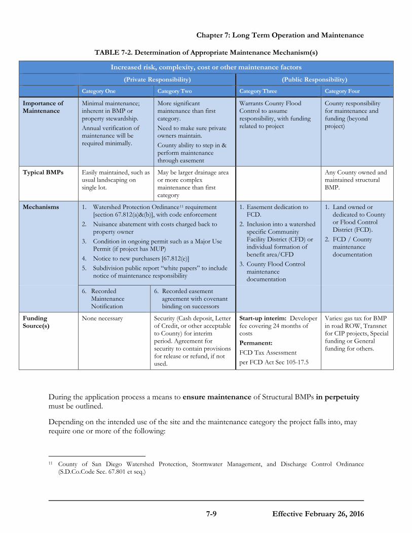
Chapter 7: Long Term Operation and Maintenance
7-9 Effective February 26, 2016
TABLE 7-2. Determination of Appropriate Maintenance Mechanism(s)
Increased risk, complexity, cost or other maintenance factors
(Private Responsibility) (Public Responsibility)
Category One Category Two Category Three Category Four
Importance of Maintenance
Minimal maintenance; inherent in BMP or property stewardship. Annual verification of maintenance will be required minimally.
More significant maintenance than first category. Need to make sure private owners maintain. County ability to step in & perform maintenance through easement
Warrants County Flood Control to assume responsibility, with funding related to project
County responsibility for maintenance and funding (beyond project)
Typical BMPs Easily maintained, such as usual landscaping on single lot.
May be larger drainage area or more complex maintenance than first category
Any County owned and maintained structural BMP.
Mechanisms
1. Watershed Protection Ordinance11 requirement [section 67.812(a)&(b)], with code enforcement
2. Nuisance abatement with costs charged back to property owner
3. Condition in ongoing permit such as a Major Use Permit (if project has MUP)
4. Notice to new purchasers [67.812(e)] 5. Subdivision public report “white papers” to include
notice of maintenance responsibility
1. Easement dedication to FCD.
2. Inclusion into a watershed specific Community Facility District (CFD) or individual formation of benefit area/CFD
3. County Flood Control maintenance documentation
1. Land owned or dedicated to County or Flood Control District (FCD).
2. FCD / County maintenance documentation
6. Recorded Maintenance Notification
6. Recorded easement agreement with covenant binding on successors
Funding Source(s)
None necessary Security (Cash deposit, Letter of Credit, or other acceptable to County) for interim period. Agreement for security to contain provisions for release or refund, if not used.
Start-up interim: Developer fee covering 24 months of costs Permanent: FCD Tax Assessment per FCD Act Sec 105-17.5
Varies: gas tax for BMP in road ROW, Transnet for CIP projects, Special funding or General funding for others.
During the application process a means to ensure maintenance of Structural BMPs in perpetuity must be outlined.
Depending on the intended use of the site and the maintenance category the project falls into, may require one or more of the following:
11 County of San Diego Watershed Protection, Stormwater Management, and Discharge Control Ordinance
(S.D.Co.Code Sec. 67.801 et seq.)

Chapter 7: Long Term Operation and Maintenance
7-10 Effective February 26, 2016
• Execution of a maintenance notification that “runs with the land” (Category 1 BMP’s).
• Creation and execution of an agreement by the owner or Home Owner’s Association (HOA) to maintain the facilities as well as an access easement and annual inspection fee (Category 2 BMP’s).
• Inclusion of the BMP(s) into a watershed specific Community Facility District or the formation of an individual district (Category 3 BMP’s).
• Dedication of fee title or easement transferring ownership of the facility (and the land under it) to the County (Category 4 BMP’s).
Templates for Maintenance Agreement Notifications and Maintenance Acceptance Memoranda are in Appendix I.3. Maintenance Agreement templates will be provided during the permit approval process by the County.
7.4 Long-Term Maintenance Documentation As part of on-going structural BMP maintenance in perpetuity, property owners are required to provide documentation of maintenance for the structural BMPs on their property to support the County’s reporting requirements to the SDRWQCB.
The MS4 Permit requires the County to verify that structural BMPs on each PDP "are adequately maintained, and continue to operate effectively to remove pollutants in storm water to the MEP through inspections, self-certifications, surveys, or other equally effective approaches." The County must also identify the party responsible for structural BMP maintenance for the PDP and report the dates and findings of structural BMP maintenance verifications, and corrective actions and/or resolutions when applicable, in their PDP inventory. The PDP inventory and findings of maintenance verifications must be reported to the SDRWQCB annually. Based on these MS4 Permit requirements, the County will require property owners to provide annual self-verification that inspection and maintenance has been performed, to provide details of the inspection results and maintenance activities, and to confirm or update the contact information for the party responsible to ensure inspection and maintenance is performed. Structural BMPs are also subject to on-site inspections by the County or its contractors to ensure the Structural BMPs are maintained and functioning properly.
7.5 Inspection and Maintenance Frequency How often is a property owner required to inspect and maintain permanent structural BMPs on their property?
The minimum inspection and maintenance frequency is annual and must be reported annually. However, actual maintenance needs are site-specific, and maintenance may be needed more frequently than annually. The need for maintenance depends on the amount and quality of runoff delivered to the structural BMP. Maintenance must be performed whenever needed, based on maintenance indicators presented in Section 7.7. The optimum maintenance frequency is each time the maintenance threshold for removal of materials (sediment, trash, debris or overgrown vegetation) is met. If this maintenance threshold has been exceeded by the time the structural BMP
Chapter 7: Long Term Operation and Maintenance
7-11 Effective February 26, 2016
is inspected, the BMP has been operating at reduced capacity. This would mean it is necessary to inspect and maintain the structural BMP more frequently. Routine maintenance will also help avoid more costly rehabilitative maintenance to repair damages that may occur when BMPs have not been adequately maintained on a routine basis.
During the first year of normal operation of a structural BMP (i.e. when the project is fully built out and occupied), inspection by the property owner's representative is recommended at least once prior to August 31 and then monthly from September through May. Where it is safe to do so, inspection during a storm event is also recommended. It is during and after a rain event when one can determine if the components of the BMP are functioning properly. After the initial period of frequent inspections, the minimum inspection and maintenance frequency can be determined based on the results of the first year inspections.
7.6 Measures to Control Maintenance Costs Because structural BMPs must be maintained into perpetuity, it is essential to include measures to control maintenance costs.
The most effective way to reduce maintenance of structural BMPs is to prevent or reduce pollutants generated onsite and delivered to the structural BMP by implementation of source control and site design BMPs onsite, as required and described in Chapter 4 of this Manual. Second, vegetated BMPs should be placed properly to reduce the potential to come under the jurisdiction of one or more resource agencies that could require permits and costly mitigation to perform maintenance of the structural BMP. Third, the structural BMP should include design features to facilitate maintenance, as listed below.
Considerations for placement of vegetated BMPs: • Locate structural BMPs outside of floodway, floodplain, and other jurisdictional areas. • Avoid direct connection to a natural surface water body. • Discuss the location of the structural BMP with a wetland biologist to avoid placing it in a
location where it could become jurisdictional or be connected to a jurisdictional area.
Measures to facilitate collection of the trapped pollutants: • Design a forebay to trap gross pollutants in a contained area that is readily accessible for
maintenance. A forebay may be a dedicated area at the inlet entrance to an infiltration BMP, biofiltration BMP, or detention basin, or may be a gross pollutant separator installed in the storm drain system that drains to the primary structural BMP.
Measures to access the structural BMP: • The BMP must be accessible to equipment needed for maintenance. Access requirements
for maintenance will vary with the type of facility selected. • Infiltration BMPs, biofiltration BMPs, and most above-ground detention basins and sand
filters will typically require routine landscape maintenance using the same equipment that is used for general landscape maintenance. At times these BMPs may require excavation of clogged media (e.g. bioretention soil media, or sand for the sand filter), and should be accessible to appropriate equipment for excavation and removal/replacement of media.
Chapter 7: Long Term Operation and Maintenance
7-12 Effective February 26, 2016
• Above-ground detention basins should include access ramps for trucks to enter the basin to bring equipment and to remove materials.
• Underground BMPs such as detention vaults, media filters, or gross pollutant separators used as forebays to other BMPs, typically require access for a vactor truck to remove materials. Proprietary BMPs such as media filters or gross pollutant separators may require access by a forklift or other truck for delivery and removal of media cartridges or other internal components. Access requirements must be verified with the manufacturer of proprietary BMPs.
• Vactor trucks are large, heavy, and difficult to maneuver. Structural BMPs that are maintained by vactor truck must include a level pad adjacent to the structural BMP, preferably with no vegetation or irrigation system (otherwise vegetation or irrigation system may be destroyed by the vactor truck).
• The sump area of a structural BMP should not exceed 20 feet in depth due to the loss of efficiency of a vactor truck. The water removal rate is three to four times longer when the depth is greater than 20 feet. Deep structures may require additional equipment (stronger vactor trucks, ladders, more vactor pipe segments).
• All manhole access points to underground structural BMPs must include a ladder or steps.
Measures to facilitate inspection of the structural BMP • Structural BMPs must include inspection ports for observing all underground components
that require inspection and maintenance. • Silt level posts or other markings must be included in all BMP components that will trap and
store sediment, trash, and/or debris, so that the inspector may determine how full the BMP is, and the maintenance personnel may determine where the bottom of the BMP is. Posts or other markings must be indicated and described on structural BMP plans.
• Vegetation requirements including plant type, coverage, and minimum height when applicable must be provided on the structural BMP and/or landscaping plans as appropriate or as required by the County. Signage indicating the location and boundary of the structural BMP is recommended.
When designing a structural BMP, the engineer should review the typical structural BMP maintenance actions listed in Section 7.7 to determine the potential maintenance equipment and access needs.
When selecting permanent structural BMPs for a project, the engineer and project owner should consider the long term cost of maintenance and what type of maintenance contracts a future property owner, homeowners association or property owners association will need to manage. The types of materials used (e.g. proprietary vs. non-proprietary parts), equipment used (e.g. landscape equipment vs. vactor truck), actions/labor expected in the maintenance process and required qualifications of maintenance personnel (e.g. confined space entry) affect the cost of long term maintenance of the structural BMPs presented in the manual.
Chapter 7: Long Term Operation and Maintenance
7-13 Effective February 26, 2016
7.7 Maintenance Indicators and Actions for Structural BMPs This Section presents typical maintenance indicators and expected maintenance actions (routine and corrective) for typical structural BMPs.
There are many different variations of structural BMPs, and structural BMPs may include multiple components. For the purpose of maintenance, the structural BMPs have been grouped into four categories based on common maintenance requirements:
• Vegetated infiltration or filtration BMPs
• Non-vegetated infiltration BMPs
• Non-vegetated filtration BMPs
• Detention BMPs
The project civil engineer is responsible for determining which categories are applicable based on the components of the structural BMP, and identifying the applicable maintenance indicators from within the category. Maintenance indicators and actions listed in Table 7-3 must be shown on the project-specific Maintenance Plan.
During inspection, the inspector checks the maintenance indicators. If one or more thresholds are met or exceeded, maintenance must be performed to ensure the structural BMP will function as designed during the next storm event.
7.7.1 Maintenance of Vegetated Infiltration or Filtration BMPs
"Vegetated infiltration or filtration BMPs" are BMPs that include vegetation as a component of the BMP. Applicable Fact Sheets include INF-2 (bioretention), PR-1 (biofiltration with partial retention), BF-1 (biofiltration) or FT-1 (vegetated swale). The vegetated BMP may or may not include amended soils, subsurface gravel layer, underdrain, and/or impermeable liner. The project civil engineer is responsible for determining which maintenance indicators and actions shown in Table 7-3 are applicable based on the components of the structural BMP.
7.7.2 Maintenance of Non-Vegetated Infiltration BMPs
"Non-vegetated infiltration BMPs" are BMPs that store storm water runoff until it infiltrates into the ground, and do not include vegetation as a component of the BMP (refer to the "vegetated BMPs" category for infiltration BMPs that include vegetation). Non-vegetated infiltration BMPs generally include non-vegetated infiltration trenches and infiltration basins, dry wells, underground infiltration galleries, and permeable pavement with underground infiltration gallery. Applicable Fact Sheets may include INF-1 (infiltration basin) or INF-3 (permeable pavement). The non-vegetated infiltration BMP may or may not include a pre-treatment device, and may or may not include above-ground storage of runoff. The project civil engineer is responsible for determining which maintenance indicators and actions shown in Table 7-4 are applicable based on the components of the structural BMP.

Chapter 7: Long Term Operation and Maintenance
7-14 Effective February 26, 2016
TABLE 7-3. Maintenance Indicators and Actions for Vegetated BMPs
Typical Maintenance Indicator(s) for Vegetated BMPs Maintenance Actions
Accumulation of sediment, litter, or debris
Remove and properly dispose of accumulated materials, without damage to the vegetation.
Poor vegetation establishment Re-seed, re-plant, or re-establish vegetation per original plans. Overgrown vegetation Mow or trim as appropriate, but not less than the design height of
the vegetation per original plans when applicable (e.g. a vegetated swale may require a minimum vegetation height).
Erosion due to concentrated irrigation flow
Repair/re-seed/re-plant eroded areas and adjust the irrigation system.
Erosion due to concentrated storm water runoff flow
Repair/re-seed/re-plant eroded areas, and make appropriate corrective measures such as adding erosion control blankets, adding stone at flow entry points, or minor re-grading to restore proper drainage according to the original plan. If the issue is not corrected by restoring the BMP to the original plan and grade, The County must be contacted prior to any additional repairs or reconstruction.
Standing water in vegetated swales Make appropriate corrective measures such as adjusting irrigation system, removing obstructions of debris or invasive vegetation, loosening or replacing top soil to allow for better infiltration, or minor re-grading for proper drainage. If the issue is not corrected by restoring the BMP to the original plan and grade, County staff in the Watershed Protection Program must be contacted prior to any additional repairs or reconstruction.
Standing water in bioretention, biofiltration with partial retention, or biofiltration areas, or flow-through planter boxes for longer than 96 hours following a storm event*
Make appropriate corrective measures such as adjusting irrigation system, removing obstructions of debris or invasive vegetation, clearing underdrains (where applicable), or repairing/replacing clogged or compacted soils.
Obstructed inlet or outlet structure Clear obstructions. Damage to structural components such as weirs, inlet or outlet structures
Repair or replace as applicable.
*These BMPs typically include a surface ponding layer as part of their function which may take 96 hours to drain following a storm event.

Chapter 7: Long Term Operation and Maintenance
7-15 Effective February 26, 2016
TABLE 7-4. Maintenance Indicators and Actions for Non-Vegetated Infiltration BMPs
Typical Maintenance Indicator(s) for Non-Vegetated Infiltration
BMPs Maintenance Actions
Accumulation of sediment, litter, or debris in infiltration basin, pre-treatment device, or on permeable pavement surface
Remove and properly dispose accumulated materials.
Standing water in infiltration basin without subsurface infiltration gallery for longer than 96 hours following a storm event
Remove and replace clogged surface soils.
Standing water in subsurface infiltration gallery for longer than 96 hours following a storm event
This condition requires investigation of why infiltration is not occurring. If feasible, corrective action must be taken to restore infiltration (e.g. flush fine sediment or remove and replace clogged soils). BMP may require retrofit if infiltration cannot be restored. If retrofit is necessary, County staff must be contacted prior to any repairs or reconstruction.
Standing water in permeable paving area
Flush fine sediment from paving and subsurface gravel. Provide routine vacuuming of permeable paving areas to prevent clogging.
Damage to permeable paving surface Repair or replace damaged surface as appropriate.
Note: When inspection or maintenance indicates sediment is accumulating in an infiltration BMP, the DMA draining to the infiltration BMP should be examined to determine the source of the sediment, and corrective measures should be made as applicable to minimize the sediment supply.
7.7.3 Maintenance of Non-Vegetated Filtration BMPs
"Non-vegetated filtration BMPs" include media filters (FT-2) and sand filters (FT-3). These BMPs function by passing runoff through the media to remove pollutants. The project civil engineer is responsible for determining which maintenance indicators and actions shown in Table 7-5 are applicable based on the components of the structural BMP.
TABLE 7-5. Maintenance Indicators and Actions for Filtration BMPs
Typical Maintenance Indicator(s) for Filtration BMPs Maintenance Actions
Accumulation of sediment, litter, or debris Remove and properly dispose accumulated materials. Obstructed inlet or outlet structure Clear obstructions.
Clogged filter media Remove and properly dispose filter media, and replace with fresh media.
Damage to components of the filtration system Repair or replace as applicable.
Note: For proprietary media filters, refer to the manufacturer's maintenance guide.

Chapter 7: Long Term Operation and Maintenance
7-16 Effective February 26, 2016
7.7.4 Maintenance of Detention BMPs
"Detention BMPs" includes basins, cisterns, vaults, and underground galleries that are primarily designed to store runoff for controlled release to downstream systems. For the purpose of the maintenance discussion, this category does not include an infiltration component (refer to "vegetated infiltration or filtration BMPs" or "non-vegetated infiltration BMPs" above). Applicable Fact Sheets may include HU-1 (cistern) or FT-4 (extended detention basin). There are many possible configurations of above ground and underground detention BMPs, including both proprietary and non-proprietary systems. The project civil engineer is responsible for determining which maintenance indicators and actions shown in Table 7-6 are applicable based on the components of the structural BMP.
TABLE 7-6. Maintenance Indicators and Actions for Detention BMPs
Typical Maintenance Indicator(s) for Detention Basins Maintenance Actions
Poor vegetation establishment Re-seed, re-establish vegetation. Overgrown vegetation Mow or trim as appropriate. Erosion due to concentrated irrigation flow
Repair/re-seed/re-plant eroded areas and adjust the irrigation system.
Erosion due to concentrated storm water runoff flow
Repair/re-seed/re-plant eroded areas and make appropriate corrective measures such as adding erosion control blankets, adding stone at flow entry points, or re-grading where necessary.
Accumulation of sediment, litter, or debris Remove and properly dispose of accumulated materials.
Standing water Make appropriate corrective measures such as adjusting irrigation system, removing obstructions of debris or invasive vegetation, or minor re-grading for proper drainage.
Obstructed inlet or outlet structure Clear obstructions. Damage to structural components such as weirs, inlet or outlet structures Repair or replace as applicable.
M O D E L B M P D E S I G N M A N U A L
8-1 Effective February 26, 2016
Chapter
8 Submittal Requirements It is necessary for County Staff to review project plans for compliance with applicable requirements of this Manual and the MS4 Permit.
The review process must verify that storm water management objectives were considered in the project planning process and that opportunities to incorporate BMPs have been identified. The review process must confirm the site plan, landscape plan, and project storm water documents are congruent. Therefore, the County requires a submittal documenting the storm water management design for every project that is subject to the requirements of this Manual. Herein the submittal is called a “SWQMP." A complete and thorough project submittal will facilitate and expedite the review and approval, and may result in fewer submittals by the applicant. The Sections below discuss submittal requirements.
8.1 Submittal Requirement for Standard Projects
8.1.1 Standard Project SWQMP
For Standard Projects, the project submittal must include a "Standard Project SWQMP."
The Standard Project SWQMP is a compilation of checklists that document that all permanent source control and site design BMPs have been considered for the project and implemented where feasible. All applicable features must be shown on site plans and landscaping plans. Project forms and checklists are included in Appendices A and I of this Manual.
The Standard Project SWQMP must also include copies of the relevant plan sheets showing source control and site design BMPs.
8.2 Submittal Requirements for PDPs
8.2.1 PDP SWQMP
For PDPs, the project submittal must include a "PDP SWQMP."
The PDP SWQMP must: 1) document that all permanent source control and site design BMPs have been adequately considered for the project and implemented where feasible; 2) document the planning process and the decisions that led to the selection of structural BMPs; 3) provide the calculations for design of structural BMPs to demonstrate that applicable performance standards are met by the structural BMP design; 4) identify maintenance requirements of the selected structural
Chapter 8: Submittal Requirements
8-2 Effective February 26, 2016
BMPs; and 5) identify the maintenance mechanism (see Sections 7.2 and 7.3) for long term maintenance of structural BMPs. PDPs must use the PDP SWQMP Template provided in Appendix A, which will include forms and/or checklists from Appendix I of the Model BMP Design Manual as well as checklists for documentation of pollutant control and hydromodification management structural BMP design. The PDP SWQMP must include copies of the relevant plan sheets showing site design, source control, and structural BMPs, and structural BMP maintenance requirements.
A PDP SWQMP must be provided with the first submittal of a project application.
Storm water requirements will directly affect the layout of the project. Storm water requirements must be considered from the initial project planning or in project concept stage, and will be reviewed upon each submittal, beginning with the first submittal. The process from initial project application through approval of the project plans often includes design changes to the site layout and features. Changes may be driven by storm water management requirements or other site requirements. Each time the site layout is adjusted, whether the adjustment is directly due to storm water management requirements identified during the County’s review of the storm water submittal, or is driven by other site requirements, the storm water management design must be revisited to ensure the revised project layout and features meet the requirements of this Manual and the MS4 Permit. An updated PDP SWQMP must be provided with each submittal of revised project plans. The updated PDP SWQMP should include documentation of changes to the site layout and features, and reasons for the changes. In the event that other site requirements identified during plan review render certain proposed storm water features infeasible (e.g. if fire department access requirements were identified that precluded use of certain surfaces or landscaping features that had been proposed), this must be documented as part of the decisions that led to the development of the final storm water management design. All Structural BMPs that are approved in the final SWQMP must be reflected on the plans.
The engineer of work is required to prepare and submit a SWQMP including all applicable exhibits, which is then reviewed by the County. Refer to Appendix A for the minimum required information to be included in the SWQMP. The County ensures that the SWQMP sufficiently demonstrates how the project will meet all of the site design (see Section 4), source control (see Section 4), and structural pollutant control BMP (see Section 5) requirements. The SWQMP should address whether the project is subject to hydromodification management requirements (see Section 6) providing structural hydromodification control BMPs, or whether the project is exempt from hydromodification requirements providing support documentation for the exemptions.
After the SWQMP has been reviewed and accepted by the County, the applicant must submit a Stormwater Maintenance Notification Agreement (Category 1) or Storm Water Maintenance Agreement (Category 2). The following items must be included in Stormwater Maintenance Notification Agreements and Stormwater Maintenance Agreements:
• Vicinity Map
• Structural BMP location(s) and dimensions
• Structural BMP cross sections and specifications. Provide model (if using a proprietary device)
• Maintenance recommendations and frequency
Additional information may be required at the discretion of the County based on the nature of the
Chapter 8: Submittal Requirements
8-3 Effective February 26, 2016
project. The Stormwater Maintenance Notification Agreement (Category 1) must be signed and notarized by the applicant; the Stormwater Maintenance Agreement (Category 2) must be signed and notarized by the applicant, and then the County Authorized Enforcement Official. Following acceptance of the SWQMP, but prior to permit issuance, the County reviews the Stormwater Maintenance Notification Agreement (Category 1), the Stormwater Maintenance Agreement (Category 2), and the development plans for consistency with the SWQMP. Once reviewed and approved, the Stormwater Maintenance Notification Agreement (Category 1) and the Stormwater Maintenance Agreement (Category 2) will be recorded against the property at the County Recorder’s Office. The recorded agreement and runs with the land, so maintenance responsibility is transferred with sale of the property. The recorded agreement gives the County legal authority to require the property owner to perform maintenance on the structural post-construction BMPs on the site. Permits will not be issued for the project unless the structural post-construction BMP information on the Stormwater Maintenance Notification Agreement (Category 1), the Stormwater Maintenance Agreement (Category 2), and development plans are consistent with the design in the approved SWQMP.
Note that additional information may be required at the discretion of the County based on the nature of the project but as a minimum the information listed in the submittal template in Appendix A must be included in the SWQMP.
Any hydrology or hydraulic calculations, soils reports or geotechnical reports prepared in support of a SWQMP must be prepared by a professional engineer with appropriate registration qualifications issued by the State of California.
8.2.1.1 PDP Maintenance Plan
While the PDP SWQMP must include general maintenance requirements for structural BMPs, the PDP SWQMP may not be the final Maintenance Plan.
The maintenance requirements documented in the PDP SWQMP must be sufficient to show that maintenance requirements have been considered in the project planning and design. However, a final Maintenance Plan should reflect actual constructed structural BMPs to be maintained. See Section 8.2.3 for project closeout procedures including local requirements for final Maintenance Plans, and Section 8.2.4 for additional requirements for private entity maintenance of structural BMPs.
8.2.2 Requirements for Construction Plans
8.2.2.1 BMP Identification and Display on Construction Plans
Plans for construction of the project (grading plans, improvement plans, and landscaping plans, as applicable) must show all permanent site design, source control, and structural BMPs, and must be congruent with the PDP SWQMP.
Design diagrams for all Structural BMPs must be illustrated on construction plans to ensure proper construction.
When construction plans are submitted for County review and approval, the reviewer will compare them with the SWQMP. By creating a Construction Plan SWQMP Checklist for the project, applicants can facilitate the project review process. Tables 8-1 and 8-2 below, must be placed on all project plans that

Chapter 8: Submittal Requirements
8-4 Effective February 26, 2016
have Structural BMPs. TABLE 8-1. Stormwater Structural Pollutant Control & Hydromodification Control BMPs (S-BMPs)
Description/Type of S-BMP Plan Sheet #
S-BMP ID# in
SWQMP
Maintenance Category
Maintenance Agreement Recorded
Doc #
Revisions
TABLE 8-2. Reference and Other Recorded Documents
Document Type Recorded Document Number
Reference Documents
Stormwater Permit Number (Discretionary and Final)
Landscape Plan Permit Number (If Applicable)
Discretionary Permit Number(s) (List all that are Applicable)
Other Recorded Documents
Encroachment Maintenance and Removal Agreement (EMRA)
(If Applicable)
Landscape Maintenance Agreement (LMA) (If Applicable) The following steps are recommended:
1. Create a table similar to Tables 8-1 and 8-2. Number and list each Structural BMP specified in the SWQMP in Column 1 and Maintenance Category in Column 4 of the table. Leave Column 2 blank. Incorporate the table into the SWQMP. List the Maintenance Agreement recorded document numbers in Column 5, if they are available.
2. When submitting construction plans, duplicate the table (by photocopy or electronically). Now fill in Column 2, identifying the plan sheets where the BMPs are shown. List all Agreement numbers in Column 5. List all plan sheets on which the BMP appears. Submit the updated table with the construction plans.
Note that the updated table—or Construction Plan SWQMP Checklist—is only a reference tool to facilitate comparison of the construction plans to your SWQMP. The County can advise applicants on the process required to propose changes to an approved SWQMP.
The construction plans will also be required to include a BMP sheet that outlines the following:
a) Entire property included on one map (use key map if multi-sheets)
Chapter 8: Submittal Requirements
8-5 Effective February 26, 2016
b) Structural BMP type, size, and dimensions for location
c) Structural BMP cross section and elevation detail (if applicable)
d) Drainage management areas
e) Points of Compliance
8.2.2.2 Structural BMP Maintenance Information on Construction Plans
Plans for construction of the project must provide sufficient information to describe maintenance requirements (thresholds and actions) for structural BMPs such that in the event all other separate maintenance documents were lost, a new party studying plans for the project could identify the structural BMPs and identify the required maintenance actions based on the plans.
For the purpose of long-term maintenance, the SWQMP must identify the following:
• How to access the structural BMP to inspect and perform maintenance;
• Features that are provided to facilitate inspection (e.g. observation ports, cleanouts, silt posts, or other features that allow the inspector to view necessary components of the structural BMP and compare to maintenance thresholds);
• Manufacturer and part number for proprietary parts;
• Maintenance thresholds specific to the structural BMP, with a location-specific frame of reference (e.g. level of accumulated materials that triggers removal of the materials, to be identified based on viewing marks on silt posts or measured with a survey rod with respect to a fixed benchmark within the BMP);
• Recommended equipment to perform maintenance; and
• When applicable, necessary special training or certification requirements for inspection and maintenance personnel such as confined space entry or hazardous waste management.
Maintenance of structural BMPs after construction and before occupancy is the responsibility of the project applicant.
8.2.3 Design Changes during Construction and Project Closeout Procedures
8.2.3.1 Design Changes during Construction
Prior to occupancy and/or intended use of any portion of a PDP, the site must be in compliance with the requirements of this Manual and the MS4 Permit.
During construction, any changes that affect the design of storm water management features must be reviewed and approved by the County. Approved documents and additional design may be required prior to implementation of design changes during construction. This might include changes to drainage patterns that occurred based on actual site grading and construction of storm water conveyance structures or substitutions to storm water management features. Just as during the design phase, when there are changes to the site layout and features, the storm water management
Chapter 8: Submittal Requirements
8-6 Effective February 26, 2016
design must be revisited to ensure the revised project layout and features meet the requirements of this Manual and the MS4 Permit.
Construction changes that affect structural BMPs should be evaluated and if necessary, a Plan Change must be processed. Submittal documents for a Plan Change may include (but not be limited) to the following:
• Original permitted set of plans redlined with changes shown bubbled and deltas added to identify proposed changes;
• Original approved SWQMP with revisions; and
• Revisions to the Drainage Study (if applicable)
If the original engineer of work is no longer available, the new engineer of work must accept the original SWQMP prior to preparation of the addendum.
8.2.3.2 Verification of Constructed BMPs
As part of the "Structural BMP Approval and Verification Process" required by the MS4 Permit Provision E.3.e(1) and WPO Section 67.811(b)(8), each structural BMP must be inspected to verify that it has been constructed and is operating in compliance with all of its specifications, plans, permits, ordinances, and the requirements of the MS4 Permit.
Since some portions of the structural BMP will not be readily visible after completion of construction (e.g. subsurface layers), the County may require inspections during construction, photographs taken during construction, and/or other verification that the BMP has been constructed in conformance with the approved plans. The County inspector may require forms or other documentation be submitted prior to the inspection in order to facilitate the structural BMP inspection. At the completion of the each phase of a project, a Verification Acceptance Package must be completed. These forms are Attachment 4 of the PDP SWQMP in Appendix A.3. This is to ensure that the Structural BMPs are constructed per the PDP SWQMP and Plans; and that all maintenance guarantees are in place. In the case of phased developments, the Verification Acceptance Package will identify what structural BMPs have been constructed for each phase of development.
The Verification Acceptance Package must be completed prior to permit closure.
The form requires the following information:
• A copy of the final accepted SWQMP and any approved addendum.
• A copy of the most current plan showing the Structural BMP Table, design diagrams of the structural BMP, and the location of each verified as-built structural BMP.
• A photograph of each structural BMP, with clear identification of the location.
• A copy of the recorded Maintenance Notification / Agreement or Maintenance Acceptance Memorandum for all Structural BMPs.
• In the case of phased developments, identification of all structural BMPs constructed thus far for the project.
Chapter 8: Submittal Requirements
8-7 Effective February 26, 2016
8.2.3.3 Final Maintenance Plan
Upon completion of project construction, the County requires a final Maintenance Plan to be submitted.
A final Maintenance Plan reflects project-specific constructed structural BMPs with project-specific drawings, photographs, and maps, and identifies specific maintenance requirements and actions for the constructed structural BMPs. The County requires a finalized Maintenance Notification / Agreement or Maintenance Acceptance Memorandum. Refer to Section 7.2 for the timeline for maintenance agreement process.
8.2.4 Additional Requirements for Private Entity Maintenance
This Section discusses private structural BMPs to be operated and maintained on private property by the property owner or manager.
8.2.4.1 Maintenance Agreements for Private Structural BMP Maintenance
For privately owned and operated structural BMPs, the County requires execution of a Maintenance Agreement document.
A maintenance agreement is a recorded document signed by the County and the property owner committing the property owner to maintain the permanent structural BMPs into perpetuity. The maintenance agreement may provide that, if the property owner fails to maintain the storm water facilities, the County may enter the property, restore the storm water facilities to operable condition, and obtain reimbursement, including administrative costs, from the property owner. The County has two major types of maintenance agreements: the Category 1 Stormwater Maintenance Notification Agreement; and the Category 2 Stormwater Maintenance Agreement. They are differentiated by: the complexity of ownership and the water quality impact should there be a failure. The size of the drainage management area that the BMP manages and the sensitivity of the waterbody into which it drains are reviewed to assess whether it would be a Category 1 or 2 Agreement.
The Category 1 Notification is appropriate when the structural BMP is simple to maintain and is owned by one property owner on one parcel. Simple maintenance would be normal landscaping activities. The Category 1 Notification requires that the Maintenance plan and location of the structural BMP be outlined on an Agreement that is registered on title at the County Recorder’s Office. This will ensure that each subsequent property owner is made aware of their responsibility to maintain the BMP and permit the County access to inspect the BMP.
The Category 2 Agreement has the same requirements as the Category 1 Notification, namely registering on title the Maintenance Plan and location of the BMPs. It is more stringent as it requires monies be retained and easement be recorded with the County. A cash deposit will be kept in the event of BMP failure and/or the County needs to repair or maintain the BMP. An easement to permit the County to inspect and to maintain the BMP, if required will also need to be part of this Agreement. Category 2 Agreements will be required when there is more than one responsible party for the maintenance (for example, the BMP treats more than one parcel); the Drainage Management Area is significant; and/or the maintenance is complex (for example, heavy equipment or technical expertise is required for proper maintenance).
Templates for the Agreements are included in Appendix I.3.

Chapter 8: Submittal Requirements
8-8 Effective February 26, 2016
If there is a Private Road Maintenance Agreement (PRMA) and the BMP is to treat the shared road, the PRMA should address how the BMP is to be maintained, as well.
For instances where projects occur in phases, Structural BMPs must be operational prior to any release and intended final use (occupancy) of that phase of development. The responsible party during the interim phase may be different than the when the project is completed. If part of the project is to be released, an Agreement must be prepared. This may mean the developer will be the responsible party. Once the total project is complete, the Agreement may need to be replaced with a new Agreement identifying a new responsible party.
BMPs in the public right-of-way must first be approved by the County Road Maintenance Division prior to permit issuance. For privately maintained BMPs, a Structural BMP Verification Acceptance Package signed by the BMP owner and construction inspector is completed prior to the submittal of the as-built drawings. The permanent BMPs are considered accepted in unison with the other improvements shown on the approved plans.
8.2.4.2 Security for Category 2 Private Structural BMP Maintenance
To prepare a Stormwater Maintenance Agreement for Category 2-type BMPs, the agreement must:
• Identify who the responsible party will be;
• Identify all the structural BMPs that are covered in the Agreement;
• Provide the calculation for annual maintenance costs for each structural BMP; and
• Provide cash security for two-years of maintenance for all structural BMPs. This money is held by the County for five years after the last structural BMP listed on this Agreement is verified as properly installed by the Verification Acceptance Package.
An easement will be required. This easement permits the County access to perform the maintenance, in the event that the responsible party fails to do so.

M O D E L B M P D E S I G N M A N U A L
9-1 Effective February 26, 2016
Bibliography ASTM International.. 2009. ASTM Standard D3385-09. Retrieved from
http://www.astm.org/Standards/D3385.htm
Breuer, L., Eckhardt, K, and Frede, H. 2003. Plant Parameter Values for Models in Temperate Climates. Ecological Modelling. 169:237-293. November.
California Department of Water Resources. 1947. Evaporation from Water Surfaces in California, A Summary of Pan Records and Coefficients, 1881 to 1946. Bulletin No. 54. California State Printing Office.
California Department of Water Resources. 2012. California Irrigation Management Information System Reference Evapotranspiration Zones.
Caltrans. 1986. Method for Determining the Percolation Rate of Soil Using a 6-inch-diameter Test Hole. California Test 750. http://www.dot.ca.gov/hq/esc/sdsee/wwe/documents/Test_750.pdf
Cedergren, H.R. 1997. Seepage, drainage, and flow nets, third ed. John Wiley and Sons, Inc., New York.
Cities and County of Riverside. 2012. Water Quality Management Plan for the Santa Margarita Region of Riverside County.
City of Los Angeles. 2011. Development Best Management Practices Handbook. Low Impact Development Manual.
City of Portland. 2008. Storm water Management Manual
City of San Diego. 2011. Guidelines for Geotechnical Reports.
City of San Diego. 2011. San Diego Low Impact Development Design Manual.
City of San Diego. 2012. Storm Water Standards.
City of Santa Barbara. 2013. Storm Water BMP Guidance Manual.
Clear Creek Solutions, Inc. 2012. San Diego Hydrology Model User Manual.
County of Los Angeles Department of Public Works. 2014. Low Impact Development, Standards Manual.
County of Orange. 2011. Model Water Quality Management Plan (Model WQMP).
County of Orange. 2011. Technical Guidance Document for the Preparation of Conceptual/Preliminary and/or Project Water Quality Management Plans (WQMPs).
County of San Bernardino. 1992. Suitability of Lots and Soils for Use of Leachlines or Seepage Pits, Soil Percolation (PERC) Test Report Standards, Onsite Waste Water Disposal System, August 1992.
County of San Diego. 2007. Low Impact Development Handbook: Stormwater Management

Bibliography
9-2 Effective February 26, 2016
Strategies.
County of San Diego. 2011. Final Hydromodification Management Plan
County of San Diego. 2012. County of San Diego SUSMP: Standard Urban Stormwater Mitigation Plan Requirements for Development Applications.
County of San Diego. 2014. Low Impact Development Handbook: Stormwater Management Strategies.
County of San Diego. 2003. Stormwater Standards Manual.
County of Ventura. 2011. Ventura County Technical Guidance Manual for Stormwater Quality Control Measures.
Darcy, H, 1856. Les fontaines publiques de la Ville de Dijon (The public fountains of the City of Dijon). Trans. Patricia Bobeck. Paris: Dalmont. (Kendall/Hunt, 2004) 506 p
Double Ring Infiltrometer Test (ASTM 3385)-ASTM International. 2009.
Emerson, C. 2008. Evaluation of Infiltration Practices as a Means to Control Stormwater Runoff. Civil and Environmental Engineering. Villanova University.
Emerson, C.H. 2008. Evaluation of Infiltration Practices as a Means to Control Stormwater Runoff. Doctoral dissertation, Villanova University. May 2008.
Galli, J. 1992. Analysis of urban stormwater BMP performance and longevity in Prince George’s County, Maryland. Metropolitan Washington Council of Governments, Washington, D.C.
Gobel, P. et al. 2004. Near-Natural Stormwater Management and its Effects on the Water Budget and Groundwater Surface in Urban Areas Taking Account of the Hydrogeological Conditions. Journal of Hydrology 299, 267-283.
Gulliver, J., Erickson, A., and Weiss, P. 2010. Optimizing Stormwater Treatment Practices: A Handbook of Assessment and Maintenance.
Hazen, A. 1892. Some Physical Properties of Sands And Gravels, With Special Reference To Their Use In Filtration. 24th Annual Rep., Massachusetts State Board of Health, Pub. Doc. No. 34, 539-556.
Hazen, A. 1911. Discussion of Dams On Sand Foundations’ by A.C. Koenig. Trans. Am. Soc. Civ. Eng., 73, 199-203
Hazen, A., 1892. Some Physical Properties of Sands and Gravels, With Special Reference to their Use in Filtration. 24th Annual Rep., Massachusetts State Board of Health, Pub. Doc. No. 34, 539-556.
Hazen, A., 1911. Discussion of Dams on Sand Foundations’ by A.C. Koenig. Trans. Am. Soc. Civ. Eng., 73, 199-203
King County Department of Natural Resources and Parks. 2009. King County, Washington Surface Water Design Manual. Retrieved from http://your.kingcounty.gov/dnrp/library/water-and-land/stormwater/surface-water-design-manual/SWDM-2009.pdf
Bibliography
9-3 Effective February 26, 2016
Lindsey, G., L. Roberts, and W. Page. 1991. Storm Water Management Infiltration. Maryland Department of the Environment, Sediment and Storm Water Administration.
Lindsey, P. and Bassuk, N. 1991. Specifying Soil Volumes to Meet the Water Needs of Mature Urban Street Trees and Trees in Containers. Journal of Arboriculture 17(6): 141-149.
Minnesota Pollution Control Agency (MPCA). (n.d.). Minnesota Stormwater Manual. Retrieved October 2014 from: http://stormwater.pca.state.mn.us/index.php/Calculating_credits_for_tree_trenches_and_tree_boxes
Orange County Watersheds Protection Program. 2011. Project-Specific Alternatives to the Interim Sizing Tool.
Philips C. and W. Kitch 2011. A review of methods for characterization of site infiltration with design recommendations. California State Polytechnic University-Pomona. http://www.csupomona.edu/~wakitch/arts/Philips_&_Kitch_2011.pdf
Phillips, E., and Kitch, W. 2011. A Review of Methods for Characterization of Site Infiltration with Design Recommendations. Journal of the Nevada Water Resources Association, Summer 2011, Vol. 6, No. 1, pp. 29-46.
Pitt, R., Chen, S., Clark, S., Lantrip, J., and C. Ong. 2008. Compaction’s Impacts on Urban Stormwater Infiltration, J. Irr. and Drainage Eng., January 2008.
Pitt, R., Chen, S., Clark, S., Swenson, J., and Ong, C. 2008. ”Compaction’s Impacts on Urban Storm-Water Infiltration.” J. Irrig. Drain Eng. 134, SPECIAL ISSUE: Urban Storm-Water Management, 652–658.
Riverside County. 2011. Riverside County - Low Impact Development BMP Design Handbook – Appendix A – Infiltration Testing http://rcflood.org/downloads/NPDES/Documents/LIDManual/Appendix%20A_Infiltration_Testing.pdf
Riverside County Copermittees. 2014. Santa Margarita Region Hydromodification Management Plan.
Riverside County Flood Control and Water Conservation District. 2011. Design Handbook for Low Impact Development Best Management Practices.
Riverside County Percolation Test (2011), California Test 750 (1986), San Bernardino County Percolation Test (1992); USEPA Falling Head Test (1980).
Rossman, Lewis A. 2010. Storm Water Management Model User's Manual Version 5.0. EPA/600/R-05/040.
San Diego County Copermittees. 2002. Model Standard Urban Storm Water Mitigation Plan for San Diego County, Port of San Diego, and Cities in San Diego County.
San Diego County Copermittees, 2011. Countywide Model SUSMP
San Diego County Copermittees. 2012. San Diego BMP Sizing Calculator Methodology
Bibliography
9-4 Effective February 26, 2016
San Diego County Copermittees. 2014. San Diego County Regional Watershed Management Area Analysis
San Diego County Copermittees. 2008. Countywide Model SUSMP.
SCCWRP. 2010. Hydromodification Screening Tools: Field Manual for Assessing Channel Susceptibility. Brian P. Bledsoe; Robert J. Hawley; Eric D. Stein; Derek B. Booth. Technical Report 606.
SCCWRP. 2012. Hydromodification Assessment and Management in California. Eric D. Stein; Felicia Federico; Derek B. Booth; Brian P. Bledsoe; Chris Bowles; Zan Rubin; G. Mathias Kondolf and Ashmita Sengupta. Technical Report 667.
Schwab, G., Fangmeier, D., Elliot, W., and Frevert, R. 1993. Soil and Water Conservation Engineering. Fourth Edition. John Wiley & Sons, Inc.
Scurlock, J., Asner, G., and Gower, S. 2001. Global Leaf Area Index from Field Measurements, 1932-2000. Data set. Available on-line [http://www.daac.ornl.gov] from Oak Ridge National Laboratory Distributed Active Archive Center, Oak Ridge, Tennessee, U.S.A. doi:10.3334/ORNLDAAC/584.
U.S. Department of the Interior, Bureau of Reclamation. 1990. “Procedure for Performing Field Permeability Testing by the Well Permeameter Method (USBR 7300-89)” in Earth Manual, Part 2. Materials Engineering Branch Research and Laboratory Services Division, Denver, Colorado.
U.S. Department of the Interior, Bureau of Reclamation. 1993. Drainage Manual: A Water Resources Technical Publication. Retrieved from http://www.usbr.gov/pmts/wquality_land/DrainMan.pdf
Urban Drainage and Flood Control District, Denver, CO. (2010). Urban Storm Drainage Criteria Manual. Volume 3, Best Management Practices.
US Department of Interior Bureau of Reclamation. 1993. Drainage Design Manual.
USEPA. 1980. Onsite Wastewater Treatment and Disposal Systems (EPA No. 625/1-80-012). Retrieved from nepis.epa.gov/Exe/ZyPURL.cgi?Dockey=300043XO.txt
USEPA. 2000. BASINS Technical Note 6 – Estimating Hydrology and Hydraulic Parameters for HSPF. EPA-823-R00-012.
USEPA. 2008. Managing Wet Weather with Green Infrastructure – Municipal Handbook: Green Streets. EPA-833-F-08-009. Retrieved from http://water.epa.gov/infrastructure/greeninfrastructure/#Design.
Washington Department of Ecology. 2012. Stormwater Management Manual for Western Washington.
Washington State Department of Ecology. 2012. Stormwater Management Manual for Western Washington - Volume 3: Hydrologic Analysis and Flow Control BMPs. Retrieved from https://fortress.wa.gov/ecy/publications/summarypages/1210030.html