santafe -mv motherboard hardware document 13h 00 pci slot1 00 12h ... source connects to one of...
TRANSCRIPT

Hardware Document
TGDFBD06-A Board Development Team
TriGem Computer Inc. 1 / 17 Revision 0.99
Santafe-MV Motherboard Hardware Document
Jan. 29, 2001
Revision 0.99

Hardware Document
TGDFBD06-A Board Development Team
TriGem Computer Inc. 2 / 17 Revision 0.99
Document Revision History
Released date Revision Description June 12, 2000 Rev. 0.9 First prepared for this document.
This document describes the major specification of the Santafe motherboard and the functional feature to be extended by the customer. The motherboard revision number is EVT1
January 9, 2001 Rev. 0.93 Santafe motherboard has come to be divided to Santafe-MV & Santafe-M & Santafe-L. HW Document is divided for each model. Contains major specifications for Santafe-MV motherboard EVT2.
January 29, 2001 Rev. 0.99 Contains major specifications for Santafe-MV motherboard Rev.A.
User’s Notice
No part of this product, including the schematics and BIOS may be reproduced, transmitted, transcribed, stored in a retrieval system, or translated into any language in any form by any means without the express written permission of TriGem Computer Inc. except the document kept by the purchaser for backup purposes.
© Copyright 2001 TriGem Computer Inc. All rights reserved
Hardware Document
TGDFBD06-A Board Development Team
TriGem Computer Inc. 3 / 17 Revision 0.99
Contents of Table
I. Introduction
1. General Description ------------------------------------------------------------ 4 2. Functional Block Diagram ------------------------------------------------------------ 6
II. System Overview
1. Major Units ----------------------------------------------------------------------------- 7 2. Upgradeability ------------------------------------------------------------------------- 8
2-1. Processor -------------------------------------------------------------------------- 8 2-2. Memory ----------------------------------------------------------------------------- 8 2-3. BIOS --------------------------------------------------------------------------------- 9 2-4. Expansion Slot -------------------------------------------------------------------- 9 2-5. Advanced Configuration and Power Interface (ACPI) ------------------- 10 2-6. Manufacturing Options ---------------------------------------------------------- 10
III. Jumpers & Connectors Descriptions
1. Motherboard Jumpers Settings ------------------------------------------------------ 11
1-1. Selection of Processor CPU Clock ---------------------------------------------- 11 1-2. Clock Setting (J6, J7, J8) ---------------------------------------------------------- 12 1-3. OEM/ODM selector (J1, J3) ------------------------------------------------------ 12 1-4. Configuration Selector (J9, J10, J11) ---------------------------------------------- 12
2. I/O Headers & Connectors Descriptions ------------------------------------------- 13 2-1.Motherboard Internal Connectors --------------------------------------------- 13 2-2.Motherboard External I/O Ports ------------------------------------------------ 16

Hardware Document
TGDFBD06-A Board Development Team
TriGem Computer Inc. 4 / 17 Revision 0.99
I. Introduction The Santafe-KM mATX motherboard offers a time-to-market consumer desktop solution featuring the AMD SocketA processor with the 200MHz front side bus and VIA KM133 chipset. The Santafe-KM motherboard was designed to have highly minimized system cost, so it is a good solution for a value PC system. Integrated AGP graphics controller core and PCI audio solution with AC97 Codec make the expensive graphic and audio add-in cards unnecessary. After all, the Santafe-KM motherboard is a good solution for the PC users with an affordable price. 1. General description
q Motherboard • PCB size in the mATX form factor • 228mm * 238mm * 1.6t (4 Layers)
q Processors • AMD socketA processors (Athlon & Duron)
q Main Chipset
• System Core (North bridge) - VIA KM133 (Includes savage4-pro video controller core)
• Super I/O & Integrated Peripheral PCI Controller (South Bridge) - VIA VT82C686A • Audio : SoundBlaster Pro Hardware and Direct Sound AC97 Audio at VT82C686A and CS4299 Codec • DC-DC Converter : Intersil HIP6302 + HIP6601 • Clock : Cypress W230 • EtherNet : Realtek RTL8139C
q Memory Configuration • System Memory - Four banks (2 DIMM) of 64-Bits Advanced Memory Controller supporting PC100 - DRAM interface runs at 100MHz speed with 200MHz FSB • Flash Memory : Programmable 2MB Flash memory
q I/O Features • Integrated standard I/O ports in the rear side - One multi-mode parallel port - One FIFO serial port - PS/2 style keyboard and mouse ports - Stacked two USB ports & one RJ-45 jack
- Three audio jack for Line-In, Line-Out and MIC-In • Other integrated extended I/O ports - Two USB port & one joystick port (both in header type) - One FIFO serial port in header type - One TV-Out header - One Speaker-Out port and one S/PDIF port (both in header type) - One CD-Audio-In port and one AUX-In port - One TV-Audio-Out port
q UltraDMA-33 / 66 Master Mode PCI EIDE Controller - Transfer rate up to 33MB/sec to cover PIO mode 4, multi-word DMA mode 2, and Ultra DMA-33/66 interface - Increased reliability using UltraDMA-66 transfer protocol - Support ATAPI compliant devices including DVD devices - Dual channel master mode PCI supporting four Enhanced IDE devices

Hardware Document
TGDFBD06-A Board Development Team
TriGem Computer Inc. 5 / 17 Revision 0.99
q Audio Subsystem (Manufacturer Option) • Built in PCI Audio Controller in VIA VT82C686A and CS4299 Codec - SoundBlaster Pro Hardware and Direct Sound Ready AC97 Digital Audio Controller - Dual full-duplex Direct Sound channels between system memory and AC97 link - 32 byte FIFO for each direct sound channel
q Graphic Subsystem (AGP) • Full Featured Accelerated Graphics Port (AGP) Controller - Supports full AGP v2.0 capability for maximum bus utilization including 2x and 4x mode transfers - Supports SideBand Addressing (SBA) mode (non-multiplexed address / data) - Supports 266 MHz 4x mode for AD and SBA signaling
- Pipelined split-transaction long-burst transfers up to 1GB/sec
q Graphic Subsystem (on chip) • Integrated S3 Savage4 AGP Graphics Controller core - Optimized Shared Memory Architecture (SMA) - From 2 to 32 MB frame buffer using system memory - Floating point triangle setup engine - Single cycle 128-bit 3D architecture - 8M triangles/second setup engine - 140M pixels/second trilinear fill rate - Full AGP 4x, including sideband addressing and execute mode - S3 DX6 texture compression (S3TC) - Next generation, 128-bit 2D graphics engine - High quality DVD video playback - Flat panel monitor support - 2D/3D resolutions up to 1920x1440

Hardware Document
TGDFBD06-A Board Development Team
TriGem Computer Inc. 6 / 17 Revision 0.99
2. Functional Block Diagram
Rear Ports
AMD SocketA
VIA VT82C686A
Host Interface
PCI Interface
DIMM Modules
3 PCI Slots
Speaker MIC Line In
Primary IDE
Secondary IDE
FDD
Super I/O Function Rear Port
MOUSE K/B
Parallel Port 2 Serial Ports
4 USB Ports
Joystick and MIDI
CS4299 Codec
VIA KM133

Hardware Document
TGDFBD06-A Board Development Team
TriGem Computer Inc. 7 / 17 Revision 0.99
II. System Overview 1. Major Units
1. Audio Power AMP : TPA1517 2. AC97 Codec : CS4299 3. North bridge : KM 133 4. PCI Ethernet controller : RTL8139 5. South bridge : VT82C686A 6. Flash ROM : W29C020P-12 7. Battery : CR2032 8. Clock generator : W230 9. DC-DC Converter : HIP6302 10. CPU Socket : AMD SocketA
2
4
5
6
3
8
10
1
7
9

Hardware Document
TGDFBD06-A Board Development Team
TriGem Computer Inc. 8 / 17 Revision 0.99
2. Upgradeability 2-1. Processor
Santafe-KM motherboard provides the 462pin SocketA which supports Athlon & Duron and is not backward compatible with ZIF socket-7 processors. The voltage regulator on the motherboard is programmed to output the required voltage by the processor itself through the processor’s VID pin.
q Suppported AMD SocketA Processors : Athlon, Duron
2-2. Memory
Santafe-KM motherboard has two, dual inline memory module (DIMM), minimum 16MB to maximum 256MB memory size. The BIOS detects the memory type, size, and speed through SMBUS interface between the core chipset and DIMM module automatically. The motherboard supports the following memory features • 3.3V and unbuffered 168-pin DIMM Voltage detection 3.3V Version 5V Version Unbuffered detection
Unbuffered Buffered • DRAM interface synchronous with host CPU (200 MHz) • Supports SDRAM memory types • Different DRAM types may be used in mixed combinations • Different DRAM timing for each bank
Hardware Document
TGDFBD06-A Board Development Team
TriGem Computer Inc. 9 / 17 Revision 0.99
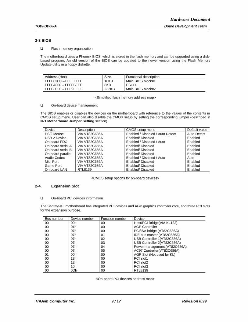
2-3 BIOS q Flash memory organization The motherboard uses a Phoenix BIOS, which is stored in the flash memory and can be upgraded using a disk-based program. An old version of the BIOS can be updated to the newer version using the Flash Memory Update utility in a floppy diskette.
Address (Hex) Size Functional description FFFFC000 – FFFFFFFF 16KB Main BIOS block#1 FFFFA000 – FFFFBFFF 8KB ESCD FFFC0000 – FFF9FFFF 232KB Main BIOS block#2
<Simplified flash memory address map>
q On-board device management The BIOS enables or disables the devices on the motherboard with reference to the values of the contents in CMOS setup menu. User can also disable the CMOS setup by setting the corresponding jumper (described in III-1 Motherboard Jumper Setting section).
Device Description CMOS setup menu Default value PS/2 Mouse VIA VT82C686A Enabled / Disabled / Auto Detect Auto Detect USB 2 Device VIA VT82C686A Enabled/ Disabled Enabled On board FDC VIA VT82C686A Enabled / Disabled / Auto Enabled On board serial A VIA VT82C686A Enabled/ Disabled Enabled On board serial B VIA VT82C686A Enabled/ Disabled Enabled On board parallel VIA VT82C686A Enabled/ Disabled Enabled Audio Codec VIA VT82C686A Enabled / Disabled / Auto Auto Midi Port VIA VT82C686A Enabled/ Disabled Enabled Game Port VIA VT82C686A Enabled/ Disabled Enabled On board LAN RTL8139 Enabled/ Disabled Enabled
<CMOS setup options for on-board devices>
2-4. Expansion Slot
q On-board PCI devices information The Santafe-KL motherboard has integrated PCI devices and AGP graphics controller core, and three PCI slots for the expansion purpose.
Bus number Device number Function number Device 00 00h 00 Host/PCI Bridge(VIA KL133) 00 01h 00 AGP Controller 00 07h 00 PCI/ISA bridge (VT82C686A) 00 07h 01 IDE bus master (VT82C686A) 00 07h 02 USB Controller 1(VT82C686A) 00 07h 03 USB Controller 2(VT82C686A) 00 07h 04 Power management (VT82C686A) 00 07h 05 AC97 Controller(VT82C686A) 01 00h 00 AGP Slot (Not used for KL) 00 13h 00 PCI slot1 00 12h 00 PCI slot2 00 10h 00 PCI slot3 00 0Dh 00 RTL8139
<On-board PCI devices address map>

Hardware Document
TGDFBD06-A Board Development Team
TriGem Computer Inc. 10 / 17 Revision 0.99
q PCI interrupt & master number routing map VIA VT82C686A PCI/ISA bridge has four programmable interrupt request input signals. Any PCI interrupt source connects to one of these interrupts signals and assigned to the free proper interrupt number by PnP BIOS.
SB INT signals
First PCI slot
Second PCI slot
Third PCI slot
On Board Ethernet
VT82C686A
PIRQA INTA INTB INTC INTC PIRQB INTB INTC INTD PIRQC INTC INTD INTA INTC PIRQD INTD INTA INTB INTD Master REQ0 REQ1 REQ2 REQ3 IDSEL AD30 AD29 AD27 AD24 AD18
? VIA VT82C694Z supports up to five REQ and GNT signals.
2-5. Advanced Configuration and Power Interface (ACPI)
The motherboard and system BIOS support the ACPI that requires an ACPI-aware operating system such as Windows-NT 5.0 or Windows 98/ME. ACPI feature include • Plug and play functionality normally contained in the BIOS • A soft-off feature that enables operating system to power off the computer • Indication LED for normal mode (Green) and suspend mode (Blinking Green) but this function is
dependent on the LED logic or BIOS control. • Support multiple wakeup events q Wakeup devices and operations
Wakeup devices Wakeup operations Power switch Wakeup from sleep state and power-off status LAN Wakeup from sleep state Modem Wakeup from sleep state
2-6. Manufacturing Options
The motherboard has several manufacturing options according to OEM/ODM requirement. Make sure that these options can be applied in the assembly stage, and it’s impossible to upgrade or change in the customer field.
Option items Selectable functionality Feature changes Joystick port Front side USB port Front side
Hardware Document
TGDFBD06-A Board Development Team
TriGem Computer Inc. 11 / 17 Revision 0.99
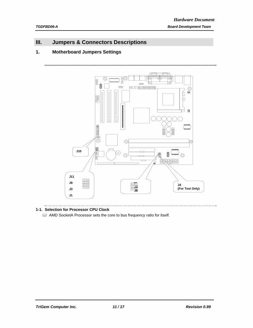
III. Jumpers & Connectors Descriptions
1. Motherboard Jumpers Settings
1-1. Selection for Processor CPU Clock & AMD SocketA Processor sets the core to bus frequency ratio for itself.
J11
J9
J3
J1
J10
J4 (For Test Only)
J7 J6 J8

Hardware Document
TGDFBD06-A Board Development Team
TriGem Computer Inc. 12 / 17 Revision 0.99
1-2. Clock Setting (J6, J7, J8)
J8 J7 J6 Host (MHz)
PCI (MHz)
Spread Spectrum(%)
1 1 1 100.0 33.3 -0.5 1 1 0 100.0 33.3 +-0.25 1 0 1 100.0 33.3 +-0.5 1 0 0 95.0 31.7 Off 0 1 1 133.3 33.3 -0.5 0 1 0 133.3 33.3 +-0.25 0 0 1 133.3 33.3 +-0.5 0 0 0 102.0 34.0 Off
Note : ‘1’ indicates connecting the pin #1 & #2, ‘0’ connecting pin #2 & #3.
1-3. OEM/ODM Selector (J1, J3)
The jumpers (J1 & J3) are optional parts for the OEM/ODM logo message selector(Not used - disabled by BIOS).
1-3. Configuration Selector (J9, J10, J11)
Function 1-2 2 – 3 CMOS CLEAR J9 Normal CMOS Clear PASSWORD J10 Normal Password Clear
SETUP J11 Normal Setup Disable

Hardware Document
TGDFBD06-A Board Development Team
TriGem Computer Inc. 13 / 17 Revision 0.99
2. I/O Headers & Connectors Descriptions 2-1. Motherboard Internal Connectors
q 1 : CPU FAN connector (CN53)
Pin number Signal description 1 GND 2 FAN control 3 Tachometer (Speed)
q 2 : Power Supply FAN connector (CN105)
Pin number Signal description 1 GND 2 FAN control 3 GND
1 2 3
CN53
1 2 3
CN105
110
9
3
7
6
5
4
28
11
12

Hardware Document
TGDFBD06-A Board Development Team
TriGem Computer Inc. 14 / 17 Revision 0.99
q 3 : System Chassis FAN connector (CN54)
Pin number Signal description 1 GND 2 FAN control 3 Tachometer (Speed)
q 4 : Indicator Header (CN73) (TG Option)
Pin Signal description 1 NC 2 GND 3 LED POWER 4 NC 5 LED POWER 6 HDD access signal 7 GND 8 Power-ON switch signal
q 5 : Joystick & USB connector (CN104) ; (Not used in ATX form Factor)
Pin Signal description Pin Signal description 1 VCC 11 VCC 2 JAB(1) 12 JBB(1) 3 JACX 13 JBCX 4 GND 14 MIDI OUT 5 GND 15 JBCY 6 JACY 16 JBB(2) 7 JAB(2) 17 MIDI IN 8 VCC 18 Key 9 GND(2) 19 USB – DATA(2) 10 USB + DATA(2) 20 VCC(2) 21 USB + DATA(3) 23 VCC(3) 22 USB – DATA(3) 24 GND(3)
Note : Blue-colored pins are for USB.
q 6 : TV Out (CN100)
Pin Signal description Pin Signal description 1 VCC 2 TV_DATA(0) 3 GND 4 GND 5 TV_DATA(9) 6 TV_DATA(1) 7 TV_DATA(10) 8 VCC 9 TV_BLANK 10 TV_DATA(2) 11 TV_DATA(11) 12 TV_DATA(3) 13 TV_VSYNC 14 GND 15 TV_HSYNC 16 TV_DATA(4) 17 RESET 18 TV_DATA(5) 19 TV_CLK_IN 20 TV_DATA(6) 21 TV_CLK_OUT 22 TV_DATA(7) 23 I2C_DATA 24 VCC 25 I2C_CLK 26 Key 27 GND 28 TV_DATA(8) 29 TV_DETECT 30 SEL_PAL
q 7 : AUX In (CN106)
1 2 3
CN54
PWR HDD DC/SW
7 8 6 5 3 2 1
30 28 26 24 22 20 18 16 14 12 10 8 6 4 2
29 27 25 23 21 19 17 15 13 11 9 7 5 3 1
22 21 10 9 8 7 6 5 4 3 2 1
24 23 20 19 18 17 16 15 14 13 12 11

Hardware Document
TGDFBD06-A Board Development Team
TriGem Computer Inc. 15 / 17 Revision 0.99
Pin Signal description 2 LEFT 3 GND 4 RIGHT
Note : 4-pinned connector is also available for the same PCB, but 3-pinned connector is used in Santafe. - Pin #1 is not used.
q 8 : Serial port (COM2 : CN25)
Pin Signal description Pin Signal description 1 DCD 6 DSR 2 RXD 7 RTS 3 TXD 8 CTS 4 DTR 9 RI 5 GND 10 KEY
q 9 : Speaker Out (CN107) Pin Signal description Pin Signal description 1 RIGHT 3 KEY 2 GND 4 LEFT
q 10 : CD Sound (CN44)
Pin Signal description 2 LEFT 3 GND 4 RIGHT
Note : 4-pinned connector is also available for the same PCB, but 3-pinned connector is used in Santafe. - Pin #1 is not used.
q 11 : S/PDIF OUT (CN58)
Pin Signal description Pin Signal description 1 S/PDIF DATA 3 NC 2 VCC 4 GND
q 12 : TV Audio In (CN45 : Only for TG models)
Pin Signal description Pin Signal description 1 LEFT 3 GND 2 GND 4 RIGHT
Hardware Document
TGDFBD06-A Board Development Team
TriGem Computer Inc. 16 / 17 Revision 0.99
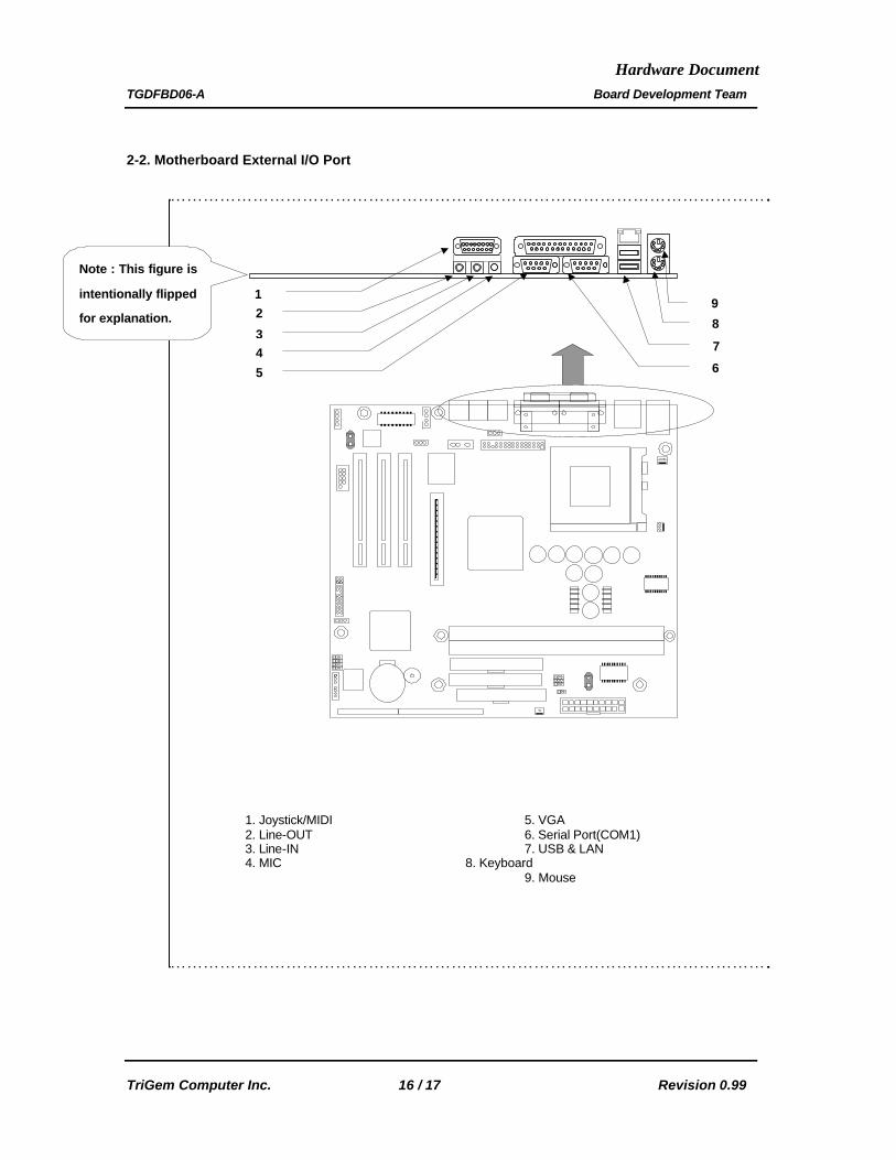
2-2. Motherboard External I/O Port
1. Joystick/MIDI 5. VGA
2. Line-OUT 6. Serial Port(COM1) 3. Line-IN 7. USB & LAN 4. MIC 8. Keyboard 9. Mouse
1
3 4
2
5 6
7
9
8
Note : This figure is
intentionally flipped
for explanation.
Hardware Document
TGDFBD06-A Board Development Team
TriGem Computer Inc. 17 / 17 Revision 0.99
Trademarks Microsoft, Windows and Windows NT are registered trademarks of Microsoft Corporation. Other product names used in this publication are for identification purpose only and may be trademarks of their respective companies.