satelline-easy user guide v2.7
TRANSCRIPT
SATELLINE-EASy
User Guide, Version 2.7
1
IMPORTANT NOTICE
All rights to this manual are owned solely by SATEL OY (referred to in this user guide as SATEL). All rights reserved. The copying of this manual (without the written permission from the owner) by printing, copying, recording or by any other means, or the full or partial translation of the manual to any other language, including all programming languages, using any electrical, mechanical, magnetic, optical, manual or other methods or devices is forbidden. SATEL reserves the right to change the technical specifications or functions of its products, or to discontinue the manufacture of any of its products or to discontinue the support of any of its products, without any written announcement and urges its customers to ensure, that the information at their disposal is valid. SATEL software and programs are delivered ”as is”. The manufacturer does not grant any kind of warranty including guarantees on suitability and applicability to a certain application. Under no circumstances is the manufacturer or the developer of a program responsible for any possible damages caused by the use of a program. The names of the programs as well as all copyrights relating to the programs are the sole property of SATEL. Any transfer, licensing to a third party, leasing, renting, transportation, copying, editing, translating, modifying into another programming language or reverse engineering for any intent is forbidden without the written consent of SATEL. SSATEL PRODUCTS HAVE NOT BEEN DESIGNED, INTENDED NOR INSPECTED TO BE USED IN ANY LIFE SUPPORT RELATED DEVICE OR SYSTEM RELATED FUNCTION NOR AS A PART OF ANY OTHER CRITICAL SYSTEM AND ARE GRANTED NO FUNCTIONAL WARRANTY IF THEY ARE USED IN ANY OF THE APPLICATIONS MENTIONED. Salo, FINLAND 2012 Copyright: 2012 SATEL Oy No part of this document may be reproduced, transmitted or stored in a retrieval system in any form or by any means without the prior written permission of SATEL Oy. This document is provided in confidence and must not be distributed to third parties without the express permission of SATEL Oy.

SATELLINE-EASy
User Guide, Version 2.7
2
RESTRICTIONS ON USE
SATELLINE-EASy radio modems have been designed to operate on frequency ranges, the exact use of which differs from one region and/or country to another. The user of a radio modem must take care that the said device is not operated without the permission of the local authorities on frequencies other than those specifically reserved and intended for use without a specific permit. SSATELLINE-EASy is allowed to be use in the following countries, either on licence free channels or on channels where the operation requires a licence. More detailed information is available at the local frequency management authority. Countries: AT, AU, BE, BG, CA, CH, CY, CZ, DE, DK, EE, ES, FI, FR, GB, GR, HR, HU, IE, IS, IN, IT, KZ, LT, LU, LV, MT, NL, NO, PL, PT, RU, RO, SE, SG, SI, SK, TR, UA, US and ZA.
WARNING! Users of SATELLINE-EASy radio modems in North America should be aware, that due to the allocation of the frequency band 406.0 – 406.1 MHz for government use only, the use of radio modem on this frequency band without a proper permit is strictly forbidden.
SATELLINE-EASy
User Guide, Version 2.7
3
PRODUCT CONFORMITY
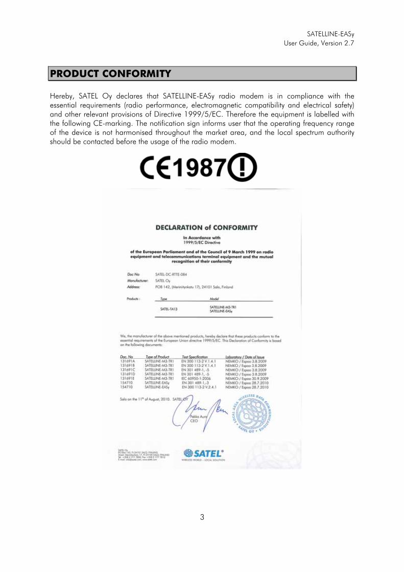
Hereby, SATEL Oy declares that SATELLINE-EASy radio modem is in compliance with the essential requirements (radio performance, electromagnetic compatibility and electrical safety) and other relevant provisions of Directive 1999/5/EC. Therefore the equipment is labelled with the following CE-marking. The notification sign informs user that the operating frequency range of the device is not harmonised throughout the market area, and the local spectrum authority should be contacted before the usage of the radio modem.
SATELLINE-EASy
User Guide, Version 2.7
4
WARRANTY AND SAFETY INSTRUCTIONS
Read these safety instructions carefully before using the product:
-Warranty will be void, if the product is used in any way that is in contradiction with the instructions given in this manual, or if the radio modem housing has been opened or tampered with.
-The radio modem is only to be operated at frequencies allocated by local authorities, and without exceeding the given maximum allowed output power ratings. SATEL and its distributors are not responsible, if any products manufactured by it are used in unlawful ways.
-The devices mentioned in this manual are to be used only according to the instructions described in this manual. Faultless and safe operation of the devices can be guaranteed only if the transport, storage, operation and handling of the devices is appropriate. This also applies to the maintenance of the products.
-To prevent damage both the radio modem and any terminal devices must always be switched OFF before connecting or disconnecting the serial connection cable. It should be ascertained that different devices used have the same ground potential. Before connecting any power cables the output voltage of the power supply should be checked.
NNOTE! When selecting a suitable location for the radio modem it must be ensured that no water can get into the radio modem under any conditions. Direct sunlight is also to be avoided. It is not recommendable to install the radio modem on a strongly vibrating surface. Suitable dampening and/or isolation materials should be used in cases where the installation surface will be subjected to vibration.
SATELLINE-EASy
User Guide, Version 2.7
5
TABLE OF CONTENTS
IMPORTANT NOTICE ......................................................................................... 1�
RESTRICTIONS ON USE ..................................................................................... 2�
PRODUCT CONFORMITY ................................................................................... 3�
WARRANTY AND SAFETY INSTRUCTIONS ......................................................... 4�
TABLE OF CONTENTS ........................................................................................ 5�
INTRODUCTION .............................................................................................. 10�
1� SATELLINE-EASY TECHNICAL SPECIFICATIONS .................................. 11�
1.1� Default settings .................................................................................... 13�
2� SERIAL INTERFACE ............................................................................. 15�
2.1� D15 connector ...................................................................................... 16�
9.1 Operating Voltage ................................................................................... 17�2.1.1� Power supply ............................................................................................................ 18�2.1.2� Fuse ......................................................................................................................... 18�
3� USER INTERFACE - WITH/WITHOUT DISPLAY ..................................... 19�
3.1� LED-indicators ...................................................................................... 19�
3.2� Display and push buttons .................................................................... 19�
4� CONNECTION CABLES ....................................................................... 22�
4.1� Port 1 ................................................................................................... 22�4.1.1� RS-232 interface ....................................................................................................... 22�4.1.2� RS-232 wiring ........................................................................................................... 22�
4.2� Port 2 ................................................................................................... 23�4.2.1� RS-232, interface, Port 2 ............................................................................................ 23�4.2.2� RS-422 interface, Port 2 ............................................................................................. 24�4.2.3� RS-422 wiring, Port 2 ................................................................................................ 25�4.2.4� TTL / LVTTL, interface, Port 2 ...................................................................................... 25�
4.3� RS-485 interface (externally connected), Port 2 .................................. 26�
SATELLINE-EASy
User Guide, Version 2.7
6
4.3.1� RS-485 wiring, Port 2 ................................................................................................ 27�
4.4� Termination of RS-422 / 485 lines ....................................................... 28�4.4.1� Connection to Profibus device .................................................................................... 28�
5� RF INTERFACE ..................................................................................... 29�
5.1� Transmitter .......................................................................................... 29�
5.2� Receiver ............................................................................................... 30�
5.3� Priority RX/TX ...................................................................................... 30�
5.4� Forward Error Correction ..................................................................... 30�
5.5� Error checking ...................................................................................... 31�
5.6� Dual radio function, separate RX/TX-frequencies .............................. 31�
5.7� Free Channel Scan (FCS) ...................................................................... 32�
5.8� User data whitening ............................................................................ 33�
5.9� Pacific Crest and TRIMTALK compatibility ........................................... 33�5.9.1� General ................................................................................................................... 33�5.9.2� Configuration in Programming menu .......................................................................... 34�5.9.3� Configuration by using SL commands ......................................................................... 34�5.9.4� Settings .................................................................................................................... 34�5.9.5� Repeater function ...................................................................................................... 36�5.9.6� Support for Local / Remote addresses ......................................................................... 37�5.9.7� Latency ..................................................................................................................... 37�5.9.7.1� Transmission delays using Option 1 (Pacific Crest 4FSK) on 25 kHz channel .................. 38�5.9.7.2� Transmission delays using Option 2 (Pacific Crest GMSK) on 25 kHz channel ................ 38�
6� TRANSPARENT DATA TRANSMISSION ............................................... 39�
6.1� Serial interface, data format ............................................................... 39�
6.2� Handshake lines .................................................................................. 40�6.2.1� CTS-line ................................................................................................................... 40�6.2.2� CD-line .................................................................................................................... 40�6.2.3� RTS-line .................................................................................................................... 41�
6.3� Timing and delays during data transmission ..................................... 41�6.3.1� Data buffering in the radio data modem ..................................................................... 41�6.3.2� Pause length ............................................................................................................. 42�6.3.3� TX delay ................................................................................................................... 43�
6.4� Testing ................................................................................................. 43�
SATELLINE-EASy
User Guide, Version 2.7
7
7� SETTINGS ........................................................................................... 45�
7.1� Programming Mode ............................................................................ 45�
8� CHANGING PARAMETERS USING A TERMINAL DEVICE ..................... 46�8.1.1� Changing the settings ................................................................................................ 46�8.1.2� Restoring factory settings ............................................................................................ 47�8.1.3� Changing frequency (active radio channel frequency) ................................................... 48�8.1.4� Changing Reference frequency ................................................................................... 49�8.1.5� Changing Channel spacing ....................................................................................... 49�8.1.6� Changing radio settings ............................................................................................. 50�8.1.7� Free channel scan ..................................................................................................... 51�8.1.8� Changing addressing settings (primary and secondary RX- and TX-addresses) ................. 52�8.1.9� Changing serial port settings (Port 1 and Port 2) .......................................................... 53�8.1.10� Modification of handshaking functions ........................................................................ 56�8.1.11� Special functions ....................................................................................................... 58�8.1.12� Modification of routing .............................................................................................. 59�8.1.13� Activating tests .......................................................................................................... 63�8.1.14� Restoring factory settings ............................................................................................ 63�8.1.15� Info .......................................................................................................................... 63�8.1.16� Saving modified settings into the permanent memory .................................................... 64�8.1.17� Updating Firmware .................................................................................................... 64�
9� CHANGING PARAMETERS USING THE LCD-DISPLAY ......................... 65�9.1.1� Changing frequency (frequency of the active TX/RX radio channel) ................................ 66�9.1.2� Changing radio settings (transmitter power and receiver sensitivity) ................................ 69�9.1.3� Changing addressing ................................................................................................ 70�9.1.4� Changing serial port settings (Port 1 and Port 2) .......................................................... 71�9.1.5� Modification of handshaking functions ........................................................................ 72�9.1.6� Selecting special functions .......................................................................................... 73�9.1.7� Activating tests .......................................................................................................... 73�9.1.8� Restoring factory settings ............................................................................................ 74�9.1.9� Adjusting the contrast of the LCD-display ..................................................................... 74�9.1.10� Saving modified values into the internal memory .......................................................... 74�
9.2� Changing parameters using the SL-COMMANDS ............................... 75�9.2.1� Frequency ................................................................................................................ 76�9.2.2� Addressing ............................................................................................................... 76�9.2.3� Radio parameters ...................................................................................................... 77�9.2.4� Other functions ......................................................................................................... 77�
10� REPEATER MODE AND ADDRESSING ................................................. 79�
10.1� Repeater .............................................................................................. 79�
10.2� Addressing ........................................................................................... 80�10.2.1� Connection between two points .................................................................................. 82�10.2.2� System of one base station and several substations ...................................................... 82�
10.3� Using repeaters and addresses in the same system .......................... 83�
SATELLINE-EASy
User Guide, Version 2.7
8
10.3.1� System with several repeaters ..................................................................................... 83�10.3.2� Repeater chain using address pairs ............................................................................. 84�10.3.3� Repeater chain using dual addressing ......................................................................... 85�10.3.4� Redundant repeater chain .......................................................................................... 85�
11� MESSAGE ROUTING ........................................................................... 86�
11.1� Introduction to Message Routing, ....................................................... 86�11.1.1� Features of Message Routing ...................................................................................... 87�11.1.2� Limitations of Message Routing .................................................................................. 87�11.1.3� Getting started with Message Routing ......................................................................... 87�11.1.4� SaTerm and the configuration of the Message Routing ................................................. 88�11.1.5� Manual configuration of the Message Routing ............................................................. 89�11.1.6� Configuration of the protocol in Message Routing ........................................................ 89�
11.2� Operating modes of Message Routing ................................................ 90�
11.3� Detailed description of Message Routing ............................................ 91�11.3.1� Source Mode Routing ................................................................................................ 91�11.3.2� Virtual Mode Routing ................................................................................................. 91�11.3.3� Overhop function in Source Mode Routing .................................................................. 91�11.3.4� Network ID ............................................................................................................... 93�
12� INSTALLATION ................................................................................... 94�
12.1� Installation of a Radio Data Modem ................................................... 94�12.1.1� Prepare installation of SATELLINE-EASy into the SATEL-321 casing ................................ 95�
12.2� Antenna installation ............................................................................ 95�12.2.1� Hand-held equipment ................................................................................................ 95�12.2.2� Mobile equipment ..................................................................................................... 95�12.2.3� Base stations ............................................................................................................. 96�12.2.4� General antenna installation instructions ..................................................................... 96�
13� DESIGNING SYSTEMS ........................................................................ 99�
13.1� Factors affecting the quality and distance of the radio connection .... 99�
13.2� Radio field strength ........................................................................... 100�
14� CHECK LIST ....................................................................................... 101�
15� ACCESSORIES ................................................................................... 102�
15.1� RS-232 cables and adapters ............................................................. 102�
15.2� RS-422/-485 cables and adapters .................................................... 102�
15.3� RF-cables ........................................................................................... 102�
SATELLINE-EASy
User Guide, Version 2.7
9
15.4� Antennas ............................................................................................ 103�
15.5� Filters and lightning protectors ......................................................... 103�
15.6� Power supplies ................................................................................... 103�
15.7� Battery pack ...................................................................................... 103�
15.8� Installation and enclosures ............................................................... 103�
16� APPENDIX A ..................................................................................... 104�
17� APPENDIX B ..................................................................................... 105�
17.1� Functional delays ............................................................................... 105�
17.2� Transmission related delays .............................................................. 105�17.2.1� Transmission delays when the radio TX frequency is changed ...................................... 106�17.2.2� Transmission delays when using a 12.5 kHz radio channel ......................................... 106�17.2.3� Transmission delays using a 25 kHz radio channel ..................................................... 108�
SATELLINE-EASy
User Guide, Version 2.7
10
INTRODUCTION
SATEL OY is a Finnish electronics and Telecommunications Company specialising in the design and manufacture of wireless data communication products. SATEL designs, manufactures and sells radio modems intended for use in applications ranging from data transfer to alarm relay systems. End users of SATEL products include both public organisations and private individuals. SATEL OY is the leading European manufacturer of radio modems. SATEL radio modems have been certified in most European countries and also in many non-European countries. Both the amount of data transferred, and the size of local area networks is increasing constantly. SATEL OY has addressed these market requirements by introducing the SATELLINE-3AS radio modem range. The SATELLINE-EASy can offer speeds up to 19.2 kbps and has a selectable serial interface between 300 … 38 400 bps. In addition to wide 70 MHz tuning range; SATELLINE-EASy also offers many other new features. These include built-in support for RS-422, TTL and LVTTL as well as the standard RS-232 interface, adjustable channel spacing and +3 … +9 V / +6 … +30 V voltage levels variations. SATELLINE-EASy include a built-in LCD display, offering the user both new features and increased flexibility. No longer do you have to rely on access to a PC or terminal device to check or alter the configuration of the unit, now this can be achieved by viewing the LCD-display and using the four (4) push buttons. The display is also a useful tool in testing the radio connection between radio modems. SATELLINE-EASy facilitates the construction of large radio networks using the built-in Message Routing function, which is both fully transparent to the user and can be used with most system protocols.
The radio modem also offers option of error correction, utilising the FEC-method (Forward Error Correction). FEC can be used to minimise errors caused by noisy channels.
SATELLINE-EASy
User Guide, Version 2.7
11
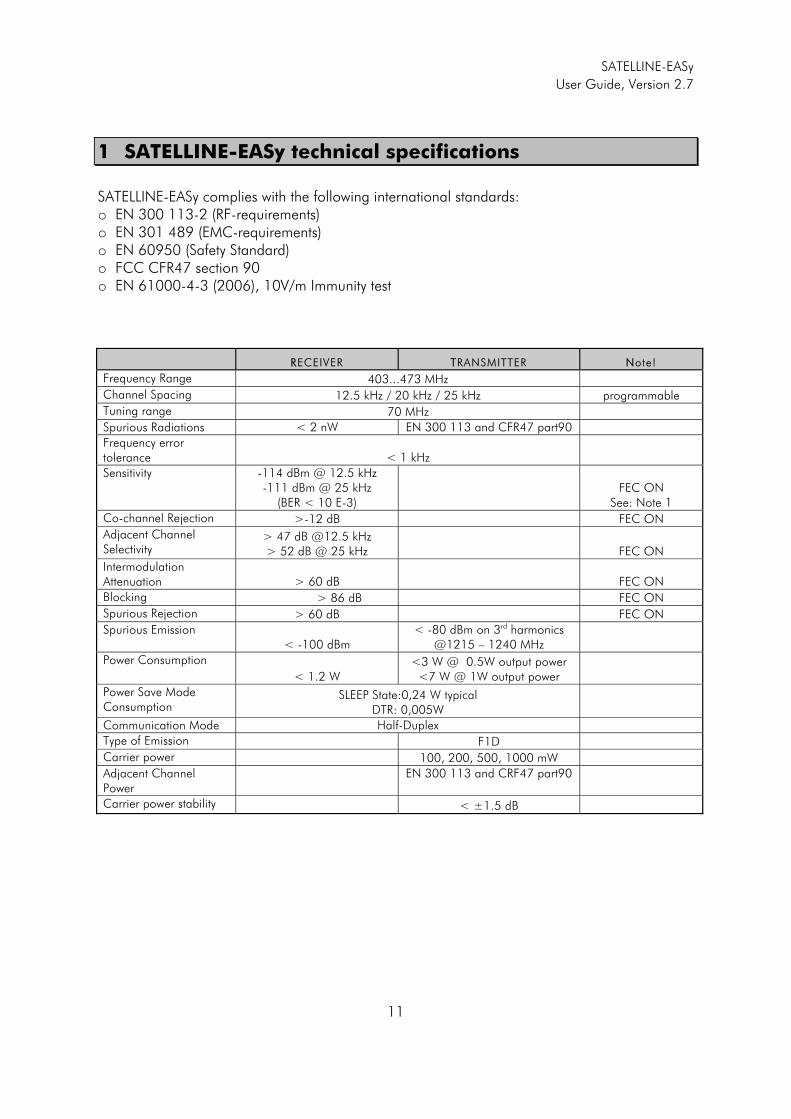
1 SATELLINE-EASy technical specifications
SATELLINE-EASy complies with the following international standards: o EN 300 113-2 (RF-requirements) o EN 301 489 (EMC-requirements) o EN 60950 (Safety Standard) o FCC CFR47 section 90 o EN 61000-4-3 (2006), 10V/m Immunity test
RRECEIVER TTRANSMITTER NNote!
Frequency Range 403...473 MHz
Channel Spacing 12.5 kHz / 20 kHz / 25 kHz programmable
Tuning range 70 MHz
Spurious Radiations < 2 nW EN 300 113 and CFR47 part90
Frequency error tolerance < 1 kHz
Sensitivity -114 dBm @ 12.5 kHz -111 dBm @ 25 kHz
(BER < 10 E-3) FEC ON
See: Note 1
Co-channel Rejection >-12 dB FEC ON
Adjacent Channel Selectivity
> 47 dB @12.5 kHz > 52 dB @ 25 kHz FEC ON
Intermodulation Attenuation > 60 dB FEC ON
Blocking > 86 dB FEC ON
Spurious Rejection > 60 dB FEC ON
Spurious Emission < -100 dBm
< -80 dBm on 3rd harmonics @1215 – 1240 MHz
Power Consumption
< 1.2 W <3 W @ 0.5W output power
<7 W @ 1W output power
Power Save Mode Consumption
SLEEP State:0,24 W typical DTR: 0,005W
Communication Mode Half-Duplex
Type of Emission F1D
Carrier power 100, 200, 500, 1000 mW
Adjacent Channel Power
EN 300 113 and CRF47 part90
Carrier power stability < ±1.5 dB
SATELLINE-EASy
User Guide, Version 2.7
12
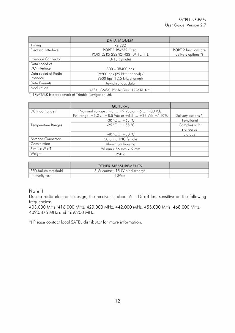
DDATA MODEM
Timing RS-232
Electrical Interface PORT 1:RS-232 (fixed) PORT 2: RS-232/RS-422, LVTTL, TTL
PORT 2 functions are delivery options *)
Interface Connector D-15 (female)
Data speed of I/O-interface 300 – 38400 bps
Data speed of Radio Interface
19200 bps (25 kHz channel) / 9600 bps (12.5 kHz channel)
Data Formats Asynchronous data
Modulation 4FSK, GMSK, PacificCrest, TRIMTALK *)
*) TRIMTALK is a trademark of Trimble Navigation Ltd.
GGENERAL
DC input ranges Nominal voltage : +3 … +9 Vdc or +6 … +30 Vdc Full range: +3.2 … +8.5 Vdc or +6.5 … +28 Vdc +/-10%. Delivery options *)
Temperature Ranges
-30 °C ... +65 °C Functional
-25 °C ... +55 °C
Complies with standards
-40 °C ... +80 °C Storage
Antenna Connector 50 ohm, TNC female
Construction Aluminium housing
Size L x W x T 96 mm x 56 mm x 9 mm
Weight 250 g
OOTHER MEASUREMENTS
ESD-failure threshold 8 kV contact, 15 kV air discharge
Immunity test 10V/m
NNote 1 Due to radio electronic design, the receiver is about 6 – 15 dB less sensitive on the following frequencies: 403.000 MHz, 416.000 MHz, 429.000 MHz, 442.000 MHz, 455.000 MHz, 468.000 MHz, 409.5875 MHz and 469.200 MHz.
*) Please contact local SATEL distributor for more information.
SATELLINE-EASy
User Guide, Version 2.7
13
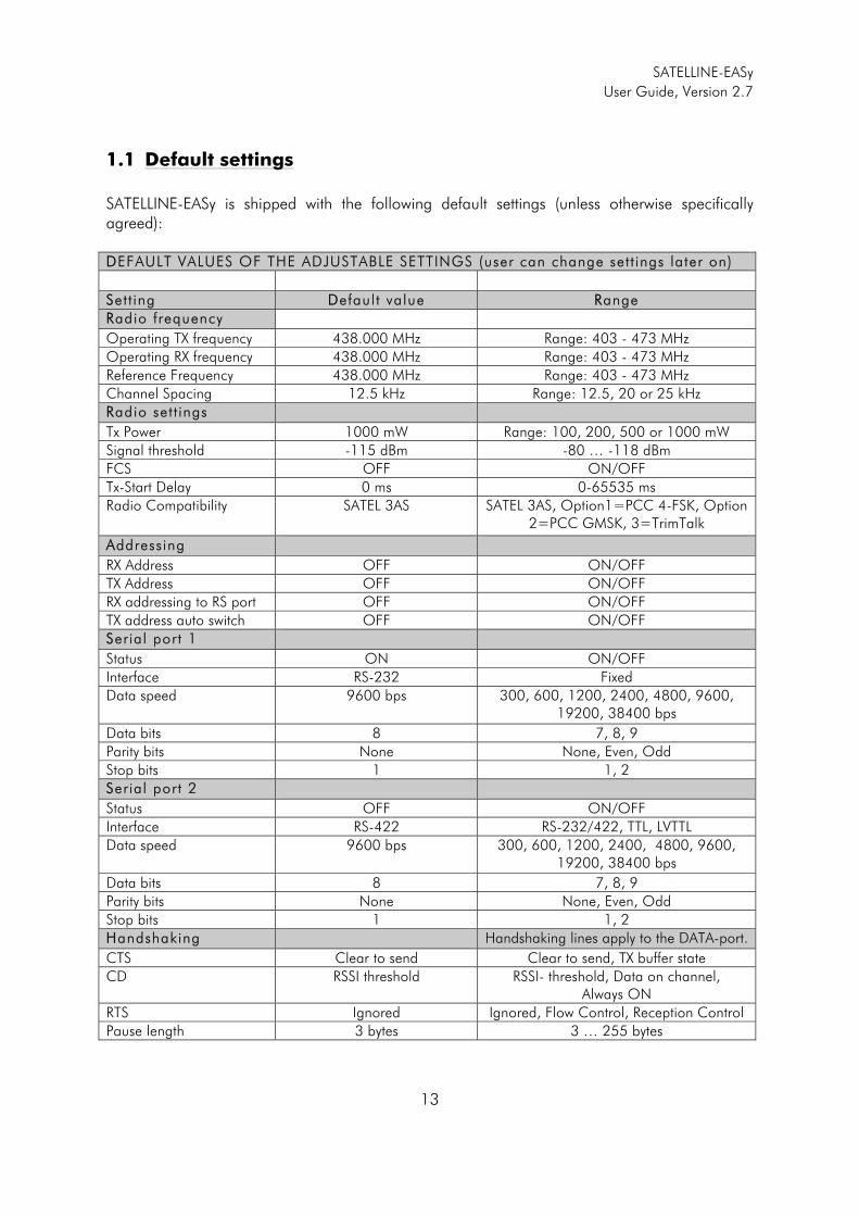
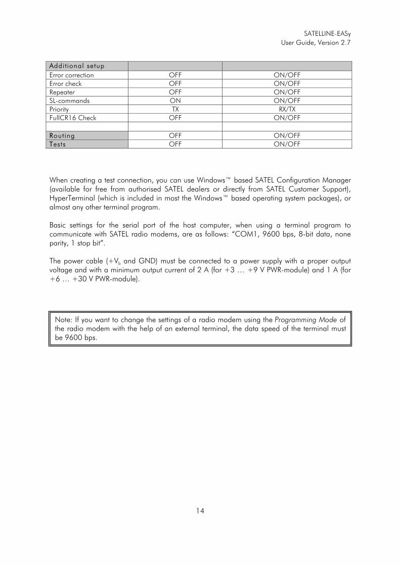
1.1 Default settings
SATELLINE-EASy is shipped with the following default settings (unless otherwise specifically agreed): DDEFAULT VALUES OF THE ADJUSTABLE SETTINGS (user can change set t ings later on) SSett ing DDefault value RRange RRadio frequency Operating TX frequency 438.000 MHz Range: 403 - 473 MHz Operating RX frequency 438.000 MHz Range: 403 - 473 MHz Reference Frequency 438.000 MHz Range: 403 - 473 MHz Channel Spacing 12.5 kHz Range: 12.5, 20 or 25 kHz RRadio set t ings Tx Power 1000 mW Range: 100, 200, 500 or 1000 mW Signal threshold -115 dBm -80 … -118 dBm FCS OFF ON/OFF Tx-Start Delay 0 ms 0-65535 ms Radio Compatibility SATEL 3AS SATEL 3AS, Option1=PCC 4-FSK, Option
2=PCC GMSK, 3=TrimTalk
AAddressing RX Address OFF ON/OFF TX Address OFF ON/OFF RX addressing to RS port OFF ON/OFF TX address auto switch OFF ON/OFF SSerial port 1 Status ON ON/OFF Interface RS-232 Fixed Data speed 9600 bps
300, 600, 1200, 2400, 4800, 9600,
19200, 38400 bps Data bits 8 7, 8, 9 Parity bits None None, Even, Odd Stop bits 1 1, 2 SSerial port 2 Status OFF ON/OFF Interface RS-422 RS-232/422, TTL, LVTTL Data speed 9600 bps
300, 600, 1200, 2400, 4800, 9600,
19200, 38400 bps Data bits 8 7, 8, 9 Parity bits None None, Even, Odd Stop bits 1 1, 2 HHandshaking Handshaking lines apply to the DATA-port. CTS Clear to send Clear to send, TX buffer state CD RSSI threshold RSSI- threshold, Data on channel,
Always ON RTS Ignored Ignored, Flow Control, Reception Control Pause length 3 bytes 3 … 255 bytes
SATELLINE-EASy
User Guide, Version 2.7
14
AAddit ional setup Error correction OFF ON/OFF Error check OFF ON/OFF Repeater OFF ON/OFF SL-commands ON ON/OFF Priority TX RX/TX FullCR16 Check OFF ON/OFF RRouting OFF ON/OFF TTests OFF ON/OFF When creating a test connection, you can use Windows™ based SATEL Configuration Manager (available for free from authorised SATEL dealers or directly from SATEL Customer Support), HyperTerminal (which is included in most the Windows™ based operating system packages), or almost any other terminal program. Basic settings for the serial port of the host computer, when using a terminal program to communicate with SATEL radio modems, are as follows: “COM1, 9600 bps, 8-bit data, none parity, 1 stop bit”. The power cable (+Vb and GND) must be connected to a power supply with a proper output voltage and with a minimum output current of 2 A (for +3 … +9 V PWR-module) and 1 A (for +6 … +30 V PWR-module).
Note: If you want to change the settings of a radio modem using the Programming Mode of the radio modem with the help of an external terminal, the data speed of the terminal must be 9600 bps.
SATELLINE-EASy
User Guide, Version 2.7
15
2 SERIAL INTERFACE
The radio modem is referred to as DCE (Data Communication Equipment) whereas the PC is referred to as DTE (Data Terminal Equipment). SATELLINE-EASy includes a 15-pin D-type female connector, which contains all the connections required to establish communication between the radio modem, acting as the DCE, and the PC, acting as the DTE. All EMC-requirements set forth by authorities have been taken into account in the design of the radio modem. The radio modem user is thereby not required to take any special actions regarding EMC-shielding (of the radio modem). The radio modem contains two separate serial ports, which are designated as PPort 1 and PPort 2. Only one port at a time can be used for communication. Port 1 Fixed - complies always with the RS-232 standard. Port 2Adjustable – settings are according to the interface module, which is installed at the factory. The default module is a dual function RS-232/RS-422. When RS-232/RS422 interface is installed, user can set on either RS-232 or RS-422. Other fixed options are LVTTL or TTL, which must be specified in the order. The user can set the Ports 1 and 2 ON/OFF afterwards in the programming mode. Only one port can be in operation at a time.
NNOTE! WHEN THE MODE-PIN (PIN 12 OF THE D-CONNECTOR) IS CONNECTED TO GROUND, THE RADIO MODEM IS IN THE PROGRAMMING MODE AND PPort 1 (PINS 7, 9, 11) IS THEN IN USE! If you normally use PPort 2 for data transmission, the serial cable must be changed to a suitable type when switching over to the configuration mode.

SATELLINE-EASy
User Guide, Version 2.7
16
2.1 D15 connector
D-15 female connector in the radio modem Direction IIN is from DTE (Data Terminal Equipment) to the radio modem. Direction OOUT is to the DTE from the radio modem.
PORT AND TYPE PIN DIRECTION NAME EXPLANATION
PORT1:RS-232
6 OUT CTS *
9 OUT RD1 Receive data (Port1)
11 IN TD1 Transmit data (Port1)
13 IN RTS *
PORT2: RS-232 / 422 232 ON / 422 OFF
2 OUT CD
3 OUT RD2 Receive data (Port2)
4 IN TD2 Transmit data (Port2)
5 OUT - -
PORT2: RS-232 / 422 422 ON / 232 OFF
2 OUT A’ Receive data positive
3 OUT B’ Receive data negative
4 IN A ** Transmit data positive
5 IN B ** Transmit data negative
PORT2: LVTTL
2 OUT CTS *
3 OUT RD Receive data (Port2)
4 IN TD Transmit data (Port2)
5 IN RTS *
PORT2: TTL
2 OUT CTS *
3 OUT RD Receive data (Port2)
4 IN TD Transmit data (Port2)
5 IN RTS *
COMMON PINS
1 IN DTR ON (Vb or NC) / STANDBY (GND)
10 OUT DSR
12 IN MODE DATA (NC) / SETUP (GND)
7, 8 - GND Power Ground
14, 15 - Vb Operating Voltage
NOTE! Unused pins can be left unconnected. *) RTS and CTS handshaking connections remain the same irrespective of the port used (Port 1 or Port 2). **) A and B designators are opposite in Profibus standard.
SATELLINE-EASy
User Guide, Version 2.7
17
Description of pins:
o RD = RReceive DData. Output of the data received from the radio modem to the DTE. o TD = TTransmit DData. Input of the data to be transmitted from the DTE to the radio modem. o CTS = CClear TTo SSend. o CD = CCarrier DDetect. o RTS = RRequest TTo SSend.
o DTR. Data Terminal Ready. When open or connected to + Voltage the unit is ready for
normal transfer mode. When connected to Ground the unit goes to low current consumption mode. OFF = <=0 V, ON = >= +3 … +30 V.
o DSR = DData SSet RReady. Indicates that the radio modem is switched ON. o MODE = operational mode. When the MODE-line is connected to ground (GND), the radio
modem enters the Programming Mode, which is used to change the settings of the radio modem (i.e. configuration, set-up). If the MODE-line is not connected, the radio modem will enter the Data Transfer Mode, in which data can be transmitted and received. The Programming Mode is used only when installing a radio modem and changing the operational parameters of a network. Normally the radio modem is always in the Data Transfer Mode.
o GND = both the negative pole of the operating voltage and the signal ground. o Vb = positive pole of the operating voltage.
9.1 Operating Voltage
The SATELLINE-EASy radio modem can have two (2) operating voltage ranges. The range is defined by the PWR-module, which is installed and set at the factory. II f not specif ically agreed the default operating voltage is +6 … +30 V. The operating voltage options are: +3.2 … +8.5 VDC or +6.5V … +28 VDC (+/-10%). The nominal voltages are +3 … +9 V and +6 … +30 V. The Input Voltage range is marked into the label. Overvoltage behaviour +3 … +9 V range:
1. When the operating voltage goes below +3 V, the modem will automatically switch OFF. 2. When the operating voltage range is exceeded, the modem will automatically switch
OFF. However, if the maximum value is more than +20 V, it may damage the module. +6 … +30 V range:
1. When the operating voltage goes below +6 V, the modem will automatically switch OFF. 2. When the nominal operating voltage is more than +33 V, it may damage the module.
SATELLINE-EASy
User Guide, Version 2.7
18
2.1.1 Power supply
The radio modem must only be connected to a power supply with an adequate current output. The pins 15 and 14 of the D-connector are connected to the positive power supply line. The pins 8 and 7 of the D-connector are connected to negative power supply line (ground). The DTR-line of the radio modem, which is connected to pin 1, can be used as an ON/STANDBY–switch, and in this way the radio modem can be switched either ON (operational state) or OFF (STANDBY). The logical state "1" (Open or more than +3.0 V, max Vdc) of the DTR-line corresponds to ON-state and a logical state "0" (.. <=0 V) corresponds to a STANDBY state. In applications, where the radio modem is used as a portable device (meaning battery operation), the DTR-line (pin 1) should be connected to a logical state "0" always when it is possible to conserve battery power and prolong operational time between battery charging. NOTE! There is a galvanic connection between signal ground (SGND, pin 7), ground (GND, pin 8), outer conductor of antenna connector and modem casing. The modem withstands a live insertion or removal from the DTE-unit without switching OFF the power.
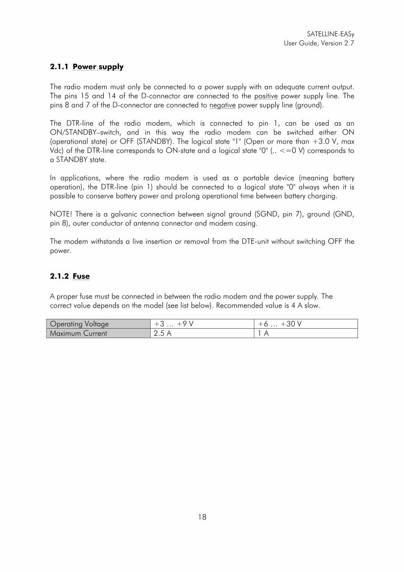
2.1.2 Fuse
A proper fuse must be connected in between the radio modem and the power supply. The correct value depends on the model (see list below). Recommended value is 4 A slow. Operating Voltage +3 … +9 V +6 … +30 V Maximum Current 2.5 A 1 A

SATELLINE-EASy
User Guide, Version 2.7
19
3 USER INTERFACE - With/without display
3.1 LED-indicators
There are five (5) LED indicators on the front panel of the radio modem, and they give an indication of the status of the serial port and the radio interface: DDescription of the LED-indicators:
1. RTS indicates the status of D-connector pin 13. 2. CTS indicates the status of D-connector pin 6. 3. TD indicates that the radio modem is receiving data via serial port. 4. RD indicates that the radio modem is sending data via serial port. 5. CD indicates the status of the radio interface. The status of the CD-signal on the serial
interface may differ from the status of the LED-indicator.
3.2 Display and push buttons
SATELLINE-EASy includes a LCD-display with a backlight. In the Data Transfer Mode the display will show the operating settings of the radio modem, for example the radio field strength and the supply voltage. By using the push buttons and the LCD-display, it is possible to change most of the settings of the radio modem, without the need for an external terminal. The display backlight illuminates automatically as soon as a button is pressed. The radio modem will shift into the Programming Mode by pressing the SETUP-push button ( �). When activated the menu shows a listing of the changeable parameters. With the help of the main menu, sub-menus can be selected which in turn can be used to change the settings. You can always return to the previous higher level of the menu structure by pressing the CANCEL (or BACK) push button. Pressing the � or � button changes settings or moves in the menu. Selections are confirmed by pressing the SELECT or SET button. In case of numerical values the digit to be changed is selected by pressing the NEXT button (see following page).
LED Indication OFF Red Orange Green
RTS RTS-line status Inactive Active
CTS CTS-line status Inactive Active
TD TD-line status No data Data Test Tx active
RD RD-line status No data Data
CD Radio status No signal Transmission Noise Reception
SATELLINE-EASy
User Guide, Version 2.7
20
SATELLINE-EASy LCD-DISPLAY AFTER POWER-UP
The display shows the basic information, which is revolving automatically in 5 seconds.
Display in Data Transfer Mode (transmit/receive mode)
n-120 11.5V TX 438.000.000 RX 438.000.000 INFO SETUP
n-120: Field strength of last received transmission or noise level.
11.5 = Supply voltage/battery level indicator. TX/RX = Operational TX and RX frequency.
n-120 11.5V Compatibility: Satel 3AS INFO SETUP
Satel 3AS is one of the radio protocols.
n-120 11.5V TX Power: 1000 mW Spacing: 25 kHz INFO SETUP
Power TX= Output transmission power. Spacing= Channel spacing
n-120 11.5V Ref 438.000.000 Com: 9600N81 INFO SETUP
Ref.= Reference frequency Communication Port Settings: 9600=Baud rate. N=No parity 8=Parity bits. 1=Stop bits.
INFO - SETUP By pressing INFO the display goes to detailed information about the modem’s settings. By pressing SETUP the modem goes to the programming menu. Display in Info mode. Pressing ��shows the next window.
SATELLINE EASy S/N: FW:06.16.3.42 Exit �
Product name Serial number FW: Firmware version
TX 438.000.000 RX 438.000.000 Ref 438.000.000 Exit ��
TX frequency RX frequency Reference frequency
SATELLINE-EASy
User Guide, Version 2.7
21
Band 1 limits Lo 403.000.000 Hi 473.000.000 Exit ��
The modem can be limited to operate only on certain frequencies. The range is shown as LO=Low and HI=High.
Band 2 limits Lo 403.000.000 Hi 473.000.000 Exit ��
The modem can be limited to operate only on certain frequencies. The range is shown as LO=Low and HI=High.
Voltage: 6-30V Port 1:RS232/ON Port2:RS232/OFF Exit ��
Voltage: Operation Voltage range. Port1: Port interface and status. Port2: Port interface and status.
Board: SPL0005c IM:05 Exit �
Board: HW version IM: Interface module type
DDisplay in Setup Mode
>Radio frequency Radio settings Exit �� Select
> The cursor indicates active line
Keypad buttons
Select-button Cancel/Back -button
Up-button Down-button
SATELLINE-EASy
User Guide, Version 2.7
22
4 CONNECTION CABLES
4.1 Port 1
4.1.1 RS-232 interface
RS-232 standard defines the method of serial data transfer between a computer and its peripherals. The definition includes both the interface type and signal levels. Most computers and peripherals contain one or more RS-232 type serial ports. The RS-232 standard uses transmission lines, in which each single signal line level is referenced, to a common ground level. RS-232 has been design to be used in serial transfer of data, in situations where the distance between communicating equipment is less than 15 m. The otherwise useful RS-232 standard is applied in a multitude of slightly differing ways, (e.g. different pin configurations) and for this reason different computers and peripherals are not necessarily directly compatible with each other.
4.1.2 RS-232 wiring
Basic RS-232 connection between the radio modem (PORT1) and a typical PC (COM-port):
NNOTE! When installing the cables of the serial interface, it is recommended that the operating voltage of all devices is powered OFF.
3
2
5
TD
RD
SGND
9-PIN D-CONN.
2
3
7
TD
RD
SGND
25-PIN D-CONN.
TD
RD
SGND
11
RADIO MODEM
9
7
1
14,15
7, 8
DTR
+Vb
GND
+Vb
GND
FuseFuse 4A slow
SATELLINE-EASy
User Guide, Version 2.7
23
Basic RS-232 connection between the radio modem (PORT1) and a typical PC (COM-port) using handshaking:
4.2 Port 2
Port 2 becomes valid only by setting it first ON. Setting can be done from the programming menu. Port2 RS-232 / RS-422 are selectable, but TTL and LVTTL are hardware related and fixed at the factory. Only one port can be ON at a time (Port 1 or Port 2). Note that when the programming mode (pin 12 connected to ground), is selected the modem will automatically use Port 1 settings (COM1, 9600 bps, 8-bit data, none parity, 1 stop bit).
4.2.1 RS-232, interface, Port 2
Basic connection between a radio modem (PORT2 in RS-232) and a typical PC (COM-port):
9-PIN D-CONN. 25-PIN D-CONN. RADIO MODEM
14,15
7, 8
+Vb
GND
3 2TD
11
+Vb
GND
2 3 RD
9
7 4RTS
13
8 5 CTS
6
6 6DSR
10
5 7 SGND
7
1 8 CD
2
4 20 DTR
1
TD
RD
RTS
CTS
DSR
SGND
CD
DTR
TD
RD
RTS
CTS
DSR
SGND
CD
DTR Fuse
4A slow
3
2
5
TD
RD
SGND
9-PIN D-CONN.
2
3
7
TD
RD
SGND
25-PIN D-CONN.
TD
RD
SGND
4
RADIO MODEM
3
7
1
14,15
7, 8
DTR
+Vb
GND
+Vb
GND
Fuse
4A slow
SATELLINE-EASy
User Guide, Version 2.7
24
4.2.2 RS-422 interface, Port 2
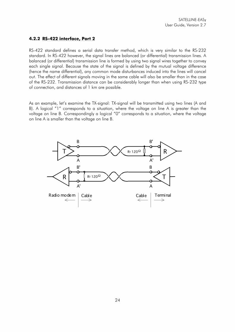
RS-422 standard defines a serial data transfer method, which is very similar to the RS-232 standard. In RS-422 however, the signal lines are balanced (or differential) transmission lines. A balanced (or differential) transmission line is formed by using two signal wires together to convey each single signal. Because the state of the signal is defined by the mutual voltage difference (hence the name differential), any common mode disturbances induced into the lines will cancel out. The effect of different signals moving in the same cable will also be smaller than in the case of the RS-232. Transmission distance can be considerably longer than when using RS-232 type of connection, and distances of 1 km are possible. As an example, let’s examine the TX-signal: TX-signal will be transmitted using two lines (A and B). A logical ”1” corresponds to a situation, where the voltage on line A is greater than the voltage on line B. Correspondingly a logical ”0” corresponds to a situation, where the voltage on line A is smaller than the voltage on line B.
RT 120 �R T
RT 120 � RT
B B'
A A'
B' B
A' A
Radio modem Cable TerminalCable
SATELLINE-EASy
User Guide, Version 2.7
25
4.2.3 RS-422 wiring, Port 2
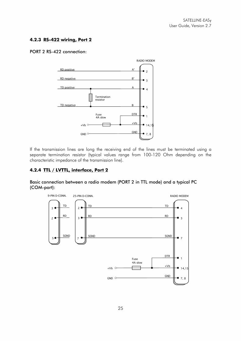
PORT 2 RS-422 connection:
If the transmission lines are long the receiving end of the lines must be terminated using a separate termination resistor (typical values range from 100-120 Ohm depending on the characteristic impedance of the transmission line).
4.2.4 TTL / LVTTL, interface, Port 2
Basic connection between a radio modem (PORT 2 in TTL mode) and a typical PC (COM-port):
A' 2
RADIO MODEM
1
14,15
7, 8
DTR
+Vb
GND
+Vb
GND
B' 3
A 4
B5
RD positive
RD negative
TD positive
TD negative
Terminatione aresistor
Fuseuse4A slow
3
2
5
TD
RD
SGND
9-PIN D-CONN.
2
3
7
TD
RD
SGND
25-PIN D-CONN.
TD
RD
SGND
4
RADIO MODEM
3
7
1
14,15
7, 8
DTR
+Vb
GND
+Vb
GND
Fuse
4A slow
SATELLINE-EASy
User Guide, Version 2.7
26
4.3 RS-485 interface (externally connected), Port 2
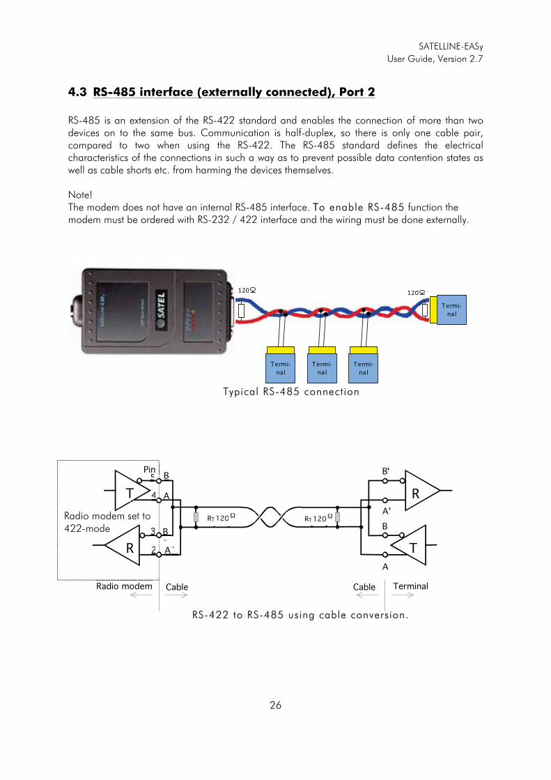
RS-485 is an extension of the RS-422 standard and enables the connection of more than two devices on to the same bus. Communication is half-duplex, so there is only one cable pair, compared to two when using the RS-422. The RS-485 standard defines the electrical characteristics of the connections in such a way as to prevent possible data contention states as well as cable shorts etc. from harming the devices themselves. Note! The modem does not have an internal RS-485 interface. TTo enable RS-485 function the modem must be ordered with RS-232 / 422 interface and the wiring must be done externally.
Typical RS-485 connection
RS-422 to RS-485 using cable conversion.
Radio modem set to 422-mode
T
R
B B'
A'
B
A
RRRT T 120 0
�
Radio modem Cable Terminal Cable
R RRTT120 0
�
R
T
B
A
B
` A`
5
4
2
3
5Pin
������
�
������
�
������
�
������
�
�
� �� �
SATELLINE-EASy
User Guide, Version 2.7
27
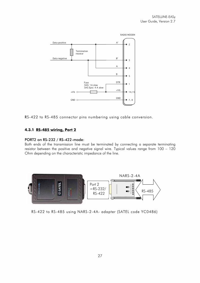
RRS-422 to RS-485 connector pins numbering using cable conversion.
4.3.1 RS-485 wiring, Port 2
PORT2 on RS-232 / RS-422-mode:Both ends of the transmission line must be terminated by connecting a separate terminating resistor between the positive and negative signal wire. Typical values range from 100 – 120 Ohm depending on the characteristic impedance of the line.
NARS-2-4A
RS-422 to RS-485 using NARS-2-4A- adapter (SATEL code YC0486)
Port 2 =RS-232/ RS-422
RS-485
A'2
RADIO MODEM
1
14,15
7, 8
DTR
+Vb
GND
+Vb
GND
B'3
A4
B5
Data positive
Data negative
Terminationresistor
Fuse 3AS: 1A slow3AS Epic: 4 A slow
SATELLINE-EASy
User Guide, Version 2.7
28
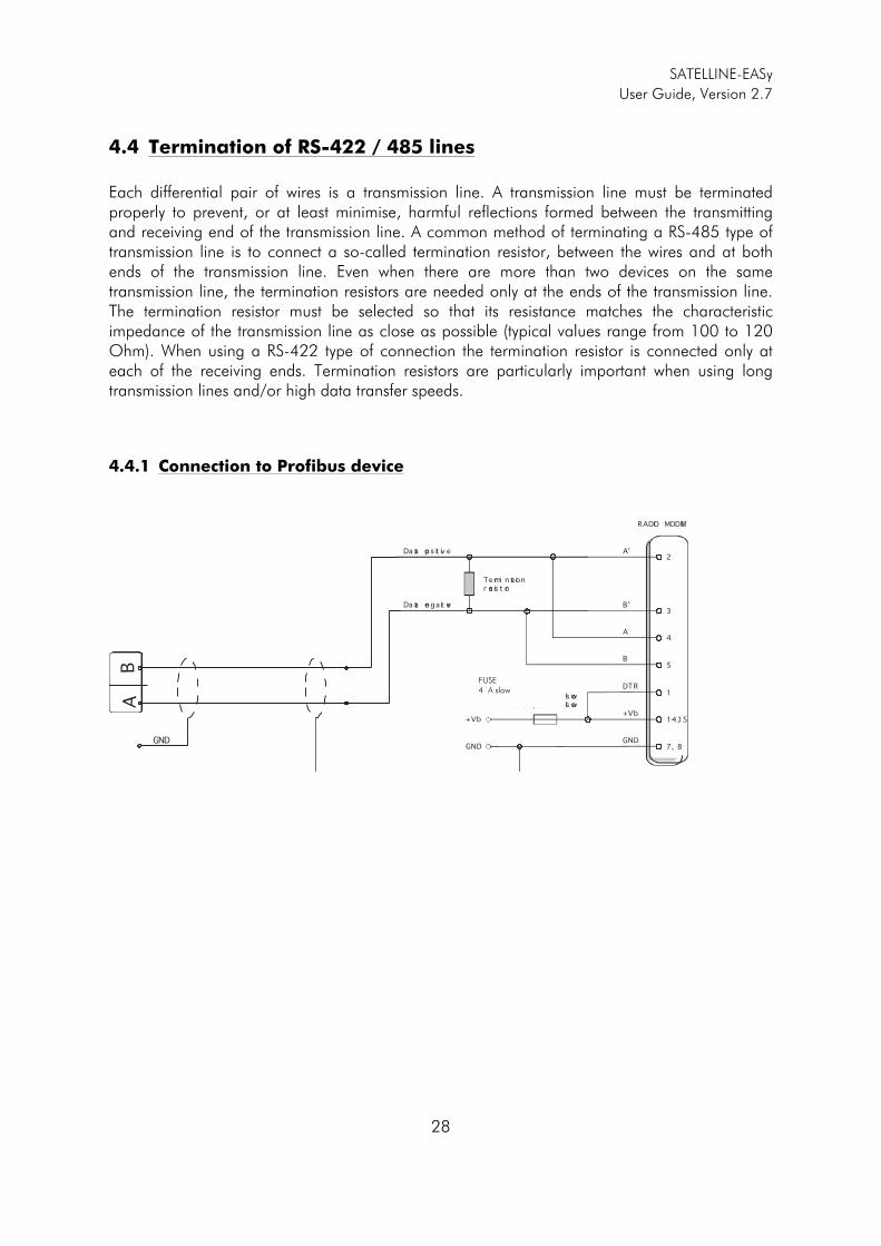
4.4 Termination of RS-422 / 485 lines
Each differential pair of wires is a transmission line. A transmission line must be terminated properly to prevent, or at least minimise, harmful reflections formed between the transmitting and receiving end of the transmission line. A common method of terminating a RS-485 type of transmission line is to connect a so-called termination resistor, between the wires and at both ends of the transmission line. Even when there are more than two devices on the same transmission line, the termination resistors are needed only at the ends of the transmission line. The termination resistor must be selected so that its resistance matches the characteristic impedance of the transmission line as close as possible (typical values range from 100 to 120 Ohm). When using a RS-422 type of connection the termination resistor is connected only at each of the receiving ends. Termination resistors are particularly important when using long transmission lines and/or high data transfer speeds.
4.4.1 Connection to Profibus device
A'2
RADIO MODEM
1
14,15
7, 8
DTR
+Vb
GND
+Vb
GND
B'3
A4
B5
Da ta po s it iv e
Da ta ne ga ti ve
Te rmi n at ionr es is t or
F u se 3AS: 630 mA sl ow3AS Ep ic : 4 A sl owA
B
GND
FUSE 4 A slow
SATELLINE-EASy
User Guide, Version 2.7
29
5 RF INTERFACE
The SATELLINE-EASy has a single RF-connector (typically TNC) with impedance of 50 Ohm. When the modem is supplied the frequency is set to “default channel”. The user can change the frequency afterwards by 70 MHz. Of course, all local regulations set forth by the authorities must be taken into consideration. The data speed of the radio interface is set to “default speed”. It can also be set afterwards. A channel spacing of 25 kHz enables a data speed of 19200 bps and a channel spacing of 12.5 / 20 kHz enables, correspondingly, a data speed of 9600 bps. The data speed of the radio interface is always fixed (19200 bps or 9600 bps) irrespective of the data speed of the serial interface. If the data speeds of the radio interface and the serial interface differ from each other, the radio modem will buffer the data in transfer temporarily, so no data loss will occur.
5.1 Transmitter
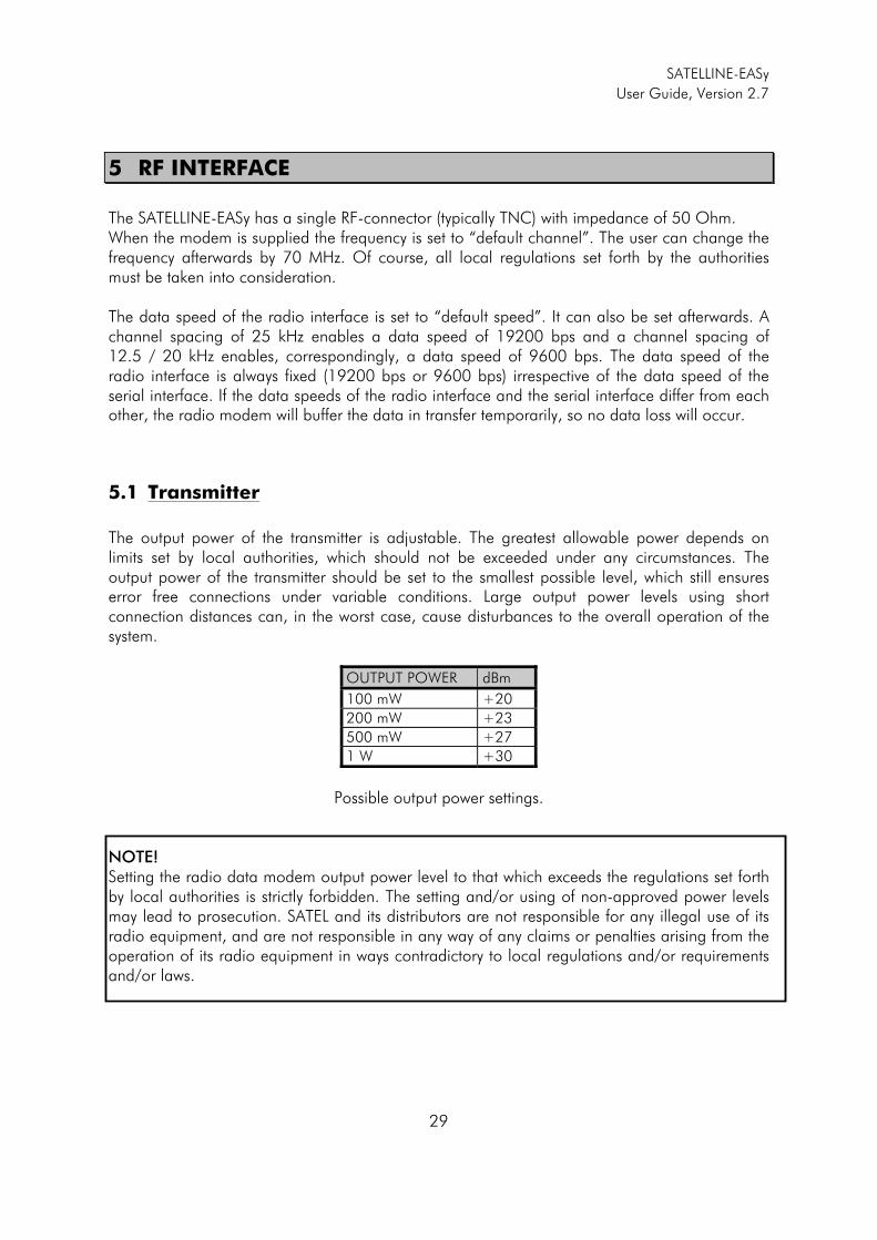
The output power of the transmitter is adjustable. The greatest allowable power depends on limits set by local authorities, which should not be exceeded under any circumstances. The output power of the transmitter should be set to the smallest possible level, which still ensures error free connections under variable conditions. Large output power levels using short connection distances can, in the worst case, cause disturbances to the overall operation of the system.
OUTPUT POWER dBm
100 mW +20
200 mW +23
500 mW +27
1 W +30
Possible output power settings.
NOTE! Setting the radio data modem output power level to that which exceeds the regulations set forth by local authorities is strictly forbidden. The setting and/or using of non-approved power levels may lead to prosecution. SATEL and its distributors are not responsible for any illegal use of its radio equipment, and are not responsible in any way of any claims or penalties arising from the operation of its radio equipment in ways contradictory to local regulations and/or requirements and/or laws.
SATELLINE-EASy
User Guide, Version 2.7
30
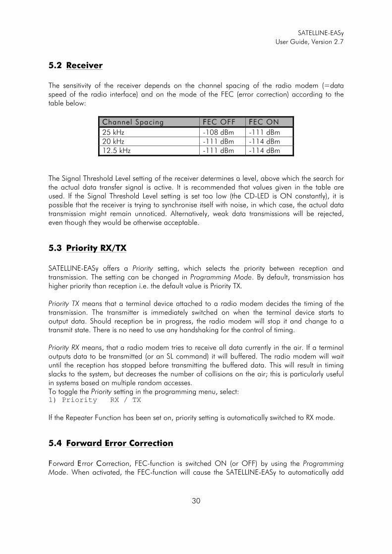
5.2 Receiver
The sensitivity of the receiver depends on the channel spacing of the radio modem (=data speed of the radio interface) and on the mode of the FEC (error correction) according to the table below:
CChannel Spacing FFEC OFF FFEC ON
25 kHz -108 dBm -111 dBm 20 kHz -111 dBm -114 dBm 12.5 kHz -111 dBm -114 dBm
The Signal Threshold Level setting of the receiver determines a level, above which the search for the actual data transfer signal is active. It is recommended that values given in the table are used. If the Signal Threshold Level setting is set too low (the CD-LED is ON constantly), it is possible that the receiver is trying to synchronise itself with noise, in which case, the actual data transmission might remain unnoticed. Alternatively, weak data transmissions will be rejected, even though they would be otherwise acceptable.
5.3 Priority RX/TX
SATELLINE-EASy offers a Priority setting, which selects the priority between reception and transmission. The setting can be changed in Programming Mode. By default, transmission has higher priority than reception i.e. the default value is Priority TX. Priority TX means that a terminal device attached to a radio modem decides the timing of the transmission. The transmitter is immediately switched on when the terminal device starts to output data. Should reception be in progress, the radio modem will stop it and change to a transmit state. There is no need to use any handshaking for the control of timing. Priority RX means, that a radio modem tries to receive all data currently in the air. If a terminal outputs data to be transmitted (or an SL command) it will buffered. The radio modem will wait until the reception has stopped before transmitting the buffered data. This will result in timing slacks to the system, but decreases the number of collisions on the air; this is particularly useful in systems based on multiple random accesses. To toggle the Priority setting in the programming menu, select: 1) Priority RX / TX
If the Repeater Function has been set on, priority setting is automatically switched to RX mode.
5.4 Forward Error Correction
FForward EError CCorrection, FEC-function is switched ON (or OFF) by using the Programming Mode. When activated, the FEC-function will cause the SATELLINE-EASy to automatically add
SATELLINE-EASy
User Guide, Version 2.7
31
additional error correction information, which increases the amount of transmitted data by 30 %. It is used by the receiving radio modem to correct erroneous bits - as long as the ratio of correct and erroneous bits is reasonable. Error correction improves the reliability of data transfer via the radio interface especially in unfavourable conditions. FEC-function should be used when link distances are long and/or if there are many disturbances in the radio channels used. The use of the FEC-function will, however decrease the data transfer throughput of data by about 30 %. The list of exact delays when using FEC-function, are introduced in appendix B. To switch the FEC-function ON in the Programming Mode, select: 1) Error correction ON
5.5 Error checking
When the error checking is switched on, the radio modem will add a checksum to the transmitted data. When the data is received, the checksums are verified before data is forwarded to the serial port. There are two different options for error checking that can be accessed in the Additional setup menu in the Programming Mode: 2) Error check
6) Full CRC16 check
Error check checks data partially while data is received. Full CRC16 check function adds two checksum characters at the end of the user data message. At the reception end the receiver receives first the whole package and if the checksum matches the data message is forwarded to the serial port. If Full CRC16 check is selected it must be set ON for all radio modems in the same network. Otherwise the checksum characters appear at the end of user message on the serial port.
5.6 Dual radio function, separate RX/TX-frequencies
The SATELLINE-EASy can transmit (TX-frequency) and receive (RX-frequency) on separate frequencies. Separate frequencies can be set within the whole tuning range. The frequencies can be set in the display menu, in the programming mode or by the Configuration Manager.
NOTE! All radio modems, which are to communicate with each other, must have the same setting for FEC (ON or OFF). If the transmitting radio modem and the receiving radio modem has different settings, data will not be received correctly.
SATELLINE-EASy
User Guide, Version 2.7
32
When data flow on the TD line starts the frequency shifts from the receiving channel to the transmit channel. There is a 40 ms delay caused by the frequency shift before the actual data transmission sequence starts, and the same time is needed for the return to the receive channel after transmission. The selected channel spacing, port settings etc. are equal to both frequencies. The dual radio settings can be adjusted also by the SL commands.
5.7 Free Channel Scan (FCS)
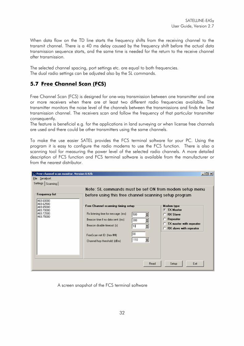
Free Channel Scan (FCS) is designed for one-way transmission between one transmitter and one or more receivers when there are at least two different radio frequencies available. The transmitter monitors the noise level of the channels between the transmissions and finds the best transmission channel. The receivers scan and follow the frequency of that particular transmitter consequently. The feature is beneficial e.g. for the applications in land surveying or when license free channels are used and there could be other transmitters using the same channels. To make the use easier SATEL provides the FCS terminal software for your PC. Using the program it is easy to configure the radio modems to use the FCS function. There is also a scanning tool for measuring the power level of the selected radio channels. A more detailed description of FCS function and FCS terminal software is available from the manufacturer or from the nearest distributor.
A screen snapshot of the FCS terminal software
SATELLINE-EASy
User Guide, Version 2.7
33
5.8 User data whitening
In some cases, if the user data includes a large number of constant characters, additional bit errors may appear. The use of error correction (FEC) is recommended in such cases. If that is not possible, the Data whitening feature can be used to improve the reliability of data transfer. The feature is set on/off in the programming mode.
5.9 Pacific Crest and TRIMTALK compatibility
5.9.1 General
SATELLINE-EASy radio modem supports additional to the original SATEL 3AS data transfer also: o Pacific Crest compatible data transfer over the air, if the opponent Pacific Crest modems
operate in the transparent mode/FEC ON/Scrambling ON that is the most common setup
among RTK applications. The other modes are currently not supported.
o TRIMTALK® 450s compatible data transfer over the air.
SATELLINE-EASy radio modem provides the following radio compatibility settings: o Option 1 for Pacific Crest 4-FSK modulation, Transparent mode/FEC ON/Scrambling ON. o Option 2 for Pacific Crest GMSK modulation, Transparent mode/FEC ON/Scrambling ON. o Option 3 for TRIMTALK GMSK modulation, Transparent mode So far, only the transparent mode is implemented, since it is the most commonly used and recommended by the user manuals. The ARQ based protocols with ACK/NACK schemes are not preferred in RTK applications that apply one-way communication. The implementation of Options 1, 2, 3 is based on the reference measurements and the available public data of the following radio modems manufactured by Pacific Crest Corporation: RFM96W, PDL HPB, PDL LPB. TRIMTALK is a trademark of Trimble Navigation Ltd.
NOTE! All radio modems, which are to communicate with each other, must have the same setting for Data whitening (ON or OFF). If the transmitting radio modem and the receiving radio modem has different settings, data will not be received correctly.
SATELLINE-EASy
User Guide, Version 2.7
34
5.9.2 Configuration in Programming menu
The correct radio compatibility mode can be changed in the Programming mode submenu Radio settings ->Radio compatibility Mode:
Radio compatibility ------------------------- 1) Satel 3AS 2) Option 1 (PCC 4-FSK) 3) Option 2 (PCC GMSK)
4) Option 3 (TRIMTALK GMSK)
5.9.3 Configuration by using SL commands
“SL@S=” command selects the compatibility mode:
o ”SL@S=0” sets SATEL 3AS (default). o ”SL@S=1” sets Option1 (PCC-4FSK) o ”SL@S=2” sets Option 2 (PCC-GMSK) o ”SL@S=3” sets Option 3 (TRIMTALK GMSK)
The modem responds with “OK” message if the requested mode is supported or “ERROR” if the mode is not allowed. “SL@S? enquires the active mode. The modem responds with a number:
o “0” if the mode is SATEL 3AS o “1” if the mode is Option 1 o “2” if the mode is Option 2 o “3” if the mode is Option 3
5.9.4 Settings
In order to use the Pacific Crest/TRIMTALK modes implemented in SATELLINE modems: PACIFIC CREST modems must have:
o Protocol Mode = o Transparent w/EOT Timeout (when using Pacific Crest modulations) o TrimTalk 450s (when using TRIMTALK GMSK modulation)
o Modulation Type depends on the system o GMSK (default, always selected when using TRIMTALK 450s mode) o 4-Level-FSK
o FEC = ON o Scrambling = ON o Data Security Code set to = 0 (=not used) o Local Address= 0…254 (0 by default)
Pacific Crest modem receives messages from SATELLINE modems that have their TX1 address matching the Local Address.
o Remote address=0…255 (255 by default, that is the broadcast address to be received by all). SATELLINE modems receive the message from a Pacific Crest radio, provided
SATELLINE-EASy
User Guide, Version 2.7
35
their RX1 address matches the Remote Address of a Pacific Crest transmitter (or if the message has the broadcast address 255).
SATELLINE modems must have the following key settings:
o FEC OFF (because the FEC here means SATEL 3AS FEC, not Pacific Crest/TRIMTALK FEC )
o Error check OFF o Full CRC16 check OFF o Radio Compatibility Option 1 in case of Pacific Crest 4-FSK o Radio Compatibility Option 2 in case of Pacific Crest GMSK o Radio Compatibility Option 3 in case of TRIMTALK GMSK o Addressing:
o When TX address is selected ON, then TX1 address is used like PDL Remote address that is the destination address for the transmitted messages. Default value is 0x00FF (=255) (note the hexadecimal format of the setting)
o When RX Address is selected ON, then RX1 address is used like PDL Local address
Default value is 0x0000 (=0) (note the hexadecimal format of the setting) Note: Addresses are NOT applicable in TRIMTALK 450s mode so SATELLINE modems must have their RX/TX addresses OFF with Option3.
The configuration tools and settings are different between SATELLINE and Pacific Crest modems:
o Pacific Crest modems are configured via the serial port using PDLCONF WindowsTM program that sends binary control messages to the serial port of the modem.
o SATELLINE-EASy radio modems are configured via the serial port using any ordinary terminal program or SATEL Configuration Manager PC-program.
The table below shows the analogy of settings between Pacific Crest and SATELLINE radio modems (status in firmware version v3. 46.3).
PPacif ic Crest sett ing CCorresponding SATELLINE-EASy sett ing Identification: Owner (not implemented) Identification: Channel Bandwidth Channel spacing Identification: RF Power TX power Radio Link: Channel Selection Type (Manual)
Radio frequency
Radio Link: Current Channel Radio frequency Radio Link: Link Rate The fixed link rates are:
Option 2 & 3: 9600bps@25kHz / [email protected] Option 1: [email protected] / [email protected]
Radio Link:Modulation Mode Compatibility->Option 1 (=PCC-4FSK) Compatibility->Option 2 (=PCC-GMSK) Compatibility->Option 3 (=TRIMTALK GMSK)
Radio Link:Scrambling ON by default Radio Link:Transmit Retries (not implemented) Radio Link:TX ACK Timeout (not implemented)
SATELLINE-EASy
User Guide, Version 2.7
36
Radio Link:Csma Monitoring Priority (RX=ON, TX=OFF) Default: RX Radio Link: AutoBase/AutoRover (not implemented) Radio Link:Digisquelch Signal threshold Radio Link:Forward Error Correction ON by default using Option 1, 2, 3
(Note: SATELLINE-EASy FEC must be OFF!) Radio Link:Local Address (0 by default) Primary RX address (RX1) (OFF by default) Radio Link:Remote Address (255 by default)
Primary TX address (TX1) (OFF by default)
Serial Interface:Protocol Mode Radio compatibility: Options 1 and 2 = Transparent w/EOT Timeout Option 3 = TRIMTALK 450s
Serial Interface:BREAK to Command (not implemented) Serial Interface:Modem Enable: Yes (not applicable) Serial Interface:Soft Break Enable (not implemented) Serial Interface:EOT value (in 0.01s units)
Pause length (in serial port byte intervals)
Serial Interface:Digipeater Delay(in0.01s units)
(not implemented)
Serial Interface:Local Node Repeater (not implemented) Frequency Table Radio frequency Data Security Code (must be 0=not used)
(not implemented)
Potential conflicts: - Pacific Crest Local/Remote addresses are supported in the firmware versions starting from v3. 46.3 - Repeater function is supported only in the firmware versions starting from v3. 46.3 - Error check and Full CRC16 check must be OFF in SATELLINE modem - FCS (Free Channel Scanning) feature is not supported by Pacific Crest radios - Message Routing is not supported by Pacific Crest radios - SATELLINE RX/TX addressing does not use ARQ scheme like Pacific Crest radios.
5.9.5 Repeater function
The implemented Pacific Crest/TRIMTALK modes support also the repeater function. The repeater function is configured either by using the SL commands:
o ”SL@M=R” (Repeater ON) o ”SL@M=O” (Repeater OFF)
or by selecting Repeater OFF/ON in the Additional setup-> Repeater programming menu. Note 1. The repeater modem passes TRIMTALK messages also to its serial port unlike for
example Pacific Crest PDL modems.
SATELLINE-EASy
User Guide, Version 2.7
37
Note 2. If error correction is ON (FEC ON) and TRIMTALK mode is activated by using ”SL@S=3” command, the firmware automatically switches SATEL FEC OFF temporarily, and turns it back at the mode return.
5.9.6 Support for Local / Remote addresses
If the modem has TX address ON then primary TX address is handled in the same way as Remote address in Pacific Crest PDL modems. The default value is 0x00FF (255 in decimal format) i.e. the broadcast address. If the modem has RX address ON then primary RX address is handled in the same way as PDL Local address in Pacific Crest PDL modems. The default value is 0x0000 (0 in decimal format). SATELLINE modem needs to have TX Delay 50ms or more in order to avoid messages from colliding in case it is to be placed in a Pacific Crest system that uses addressing and acknowledging scheme. In case only broadcast messages are used (like in RTK applications) there is usually no need for TX Delay, except if the transfer delays identical to Pacific Crest modems are preferred – in such cases an appropriate value of TX Delay is 34 ms. Note 1. SATELLINE-modems do not support Pacific Crest retransmit/acknowledge scheme.
However, that has no effect in RTK applications because they utilize only broadcast messages.
5.9.7 Latency
In the PCC Transparent protocol mode (Option 1 and Option 2) the whole message is first read from the serial port and after that it will be framed and transmitted over the radio. The end of the message is detected when there is a pause in data coming from the serial port. The symbol rates for the Pacific Crest 4FSK (Option1) are:
o 19200 bps on 25 kHz channel o 9600 bps on 12.5 kHz channel
The symbol rates for the Pacific Crest GMSK (Option2) are:
o 9600 bps on 25 kHz channel o 4800 bps on 12.5 kHz channel
The actual raw data rate is appr. 2/3 of the symbol rate.
SATELLINE-EASy
User Guide, Version 2.7
38
5.9.7.1 Transmission delays using Option 1 (Pacific Crest 4FSK) on 25 kHz channel
The table below presents the typical latency vs. the size of the message. The delays are measured from the end of transmitted data to the end of received data on the serial interface.
Number of bytes sent BBps 11 110 1100 5500
11200 77 ms 159 ms 971 ms 4590 ms
44800 48 ms 68 ms 317 ms 1438 ms
99600 43 ms 52 ms 209 ms 912 ms
119200 40 ms 45 ms 154 ms 650 ms
338400 39 ms 41 ms 127 ms 519 ms
5.9.7.2 Transmission delays using Option 2 (Pacific Crest GMSK) on 25 kHz channel
The table below presents the typical latency vs. the size of the message. The delays are measured from the end of transmitted data to the end of received data on the serial interface.
Number of bytes sent BBps 11 110 1100 5500
11200 86 ms 168 ms 1042 ms 4949 ms
44800 57 ms 77 ms 390 ms 1796 ms
99600 52 ms 62 ms 281 ms 1272 ms
119200 50 ms 55 ms 226 ms 1009 ms
338400 48 ms 51 ms 198 ms 878 ms
SATELLINE-EASy
User Guide, Version 2.7
39
6 TRANSPARENT DATA TRANSMISSION
6.1 Serial interface, data format
The SATELLINE-EASy serial interface uses an asynchronous data format. No external synchronising signal is needed, since necessary timing information is acquired from the start and stop bits transmitted before and after each data field bits (byte).
The data transfer speed of the serial interfaces can be set to 300, 600, 1200, 2400, 4800, 9600, 19200 or 38400 bps (bbits pper ssecond). The length of the data field must be 7, 8 or 9 bits. When using a data field length of 7 or 8 bits, a parity bit may also be used.
One character to be transmitted will thus contain a start bit; the data bits (which define the specific character in question); an optional parity bit and one or two stop bits. The overall length of one character is therefore 10, 11 or 12 bits. This should be taken into account when calculating the data throughput capability of a system. In other words, the number of start, stop and parity bits must be considered. A useful rule of thumb is that at a data transfer speed of 9600 bps, the transmission of one character will require roughly one millisecond (1 ms).
Start Data Parity End
Asynchronous character data format
EExample: With an 8-bit data character length and taking, for example, a decimal value of ”204”, (which corresponds to a binary value of ”11001100”) and with a start bit value of ”0”, parity bit set to either “NO” (NONE), ”0” or ”1” and with a stop bit value of ”1”, the possible combinations are listed in the table below:
DATA FORMAT CHARACTER CHARACTER LENGTH
8 bit, no parity, 1 stop bit 0110011001 10 bit
8 bit, even parity, 1 stop bit 01100110001 11 bit
8 bit, odd parity, 1 stop bit 01100110011 11 bit
8 bit, no parity, 2 stop bits 01100110011 11 bit
8 bit, even parity, 2 stop bits 011001100011 12 bit
8 bit, odd parity, 2 stop bits 011001100111 12 bit
If the settings of data speed, character length, parity or the number of stop bits differ between the radio modem and the terminal, errors will be introduced into the transferred data. The serial port settings of each individual radio modem in a system can all be different apart from the data length setting (7, 8 or 9 bits), which must always be the same in each individual radio data modem. In other words, the serial port used, the data transfer speed, parity and number of stop bits; can be different in different parts of a same system. This is especially useful where one part of the system uses an RS-485 serial port and another part uses the RS-232 serial port. In other words, radio modems may also be utilised as serial port adapters in addition to the more common role of wireless data transfer.
The serial port settings can be changed in the Programming Mode.
SATELLINE-EASy
User Guide, Version 2.7
40
6.2 Handshake lines
When using the RS-232 serial interface, handshake signals can be used to control data transfer. Handshake signals are used, for example, by the radio modem to inform the terminal that the radio channel is busy, and that it cannot initiate transmission. The terminal can also control the radio modem via RTS-line.
Line Direction
CTS To terminal
RTS To modem
CD To terminal
A common way of using handshaking signals is to monitor the CTS-line and ignore the others. Usually the terminal is fast enough to handle the data received by the radio modem, so the use of RTS-line is not necessary. Handshaking is not needed if the system protocol is designed to prevent collisions (data contention) by the use of polling, or if there is little traffic and also if there is no harm from occasional data contention situations (several radio modems try to transmit at the same time).
6.2.1 CTS-line
The options for CTS-line are: 1) CClear To Send CTS is active when the radio modem is ready to accept data for new transmission. CTS will shift into inactive state during data reception and transmission. 2) TTX buffer state CTS will shift into inactive state only if the radio modem’s TX buffer is in danger of overflowing. This typically happens when the serial interface data transfer speed is greater than the radio interface transfer speed and the size of transmitted messages is large.
6.2.2 CD-line
The options for CD-line are: 1) RRSSI-threshold CD is active whenever a signal with a level exceeding the level required for reception exists on the radio channel. It doesn’t make any difference if the signal is an actual data transmission, a signal of a radio transmitter not belonging to the system, or even an interference signal caused for example, by a computer or a peripheral device. CD is also active when the radio modem in question is transmitting.
SATELLINE-EASy
User Guide, Version 2.7
41
2) DData on channel CD will switch to active state only after recognition of a valid data transmission. CD will not react to interference signals.
3) AAlways ON CD is always in the active state. This option can be used with terminal equipment, which use the CD-line as an indicator of an active connection (the radio modem can transmit and receive at any time).
6.2.3 RTS-line
The options for RTS-line are: 1) IIgnored RTS-line status is ignored. 2) FFlow control The radio modem transmits data to the terminal device only when the RTS-line is active. Non-active state of the RTS-line will force the radio modem to buffer the received data. This option is used if the terminal device is too slow to handle data received from the radio modem. 3) RReception control RTS-line controls the reception process of the radio modem. An active RTS-line enables reception (as normal). Non-active RTS-line will interrupt reception process immediately, even if the radio modem is receiving a data packet. This option is used to force the radio modem into WAIT State for an immediate channel change.
6.3 Timing and delays during data transmission
When using a radio modem for data transmission, certain delays will be formed through the use of a radio interface and from the radio modem circuitry itself. These delays exist when the radio modem switches from Standby Mode to Data Transfer Mode and during reception and transmission of data. For detailed delay values in each case see Appendix B.
6.3.1 Data buffering in the radio data modem
Whenever the radio modem is in Data Transfer Mode it monitors both the radio channel and the serial interface. When the terminal device starts data transmission the radio modem switches to transmission mode. At the beginning of each transmission a synchronisation signal is transmitted and this signal is detected by another radio modem, which then switches into receive mode. During the transmission of the synchronisation signal the radio modem buffers data into its memory. Transmission ends when a pause is detected in the data sent by the terminal device, and after all buffered data has been transmitted. When the serial interface speed is the same or slower than the speed of the radio interface, the internal transmit buffer memory cannot
SATELLINE-EASy
User Guide, Version 2.7
42
overflow. However, when the serial interface speed exceeds the speed of the radio interface, data will eventually fill transmit buffer memory. In this instance, it will take a moment after the terminal device has stopped transmission of data for the radio modem to empty the buffer and before the transmitter switches off. The maximum size of transmit buffer memory is one kilobyte (1 kB). If the terminal device does not follow the status of the CTS-line and transmits too much data to the radio modem, the buffer will be emptied and the transmission is restarted. In the receive mode, the buffer works principally in the above described way thus evening out differences in data transfer speeds. If the terminal device transmits data to a radio modem in receive mode, the data will go into transmit buffer memory. Transmission will start immediately when the radio channel is available.
6.3.2 Pause length
The modem recognises a pause on the serial line (a pause is defined as a time with no status changes on the RS-232 interface TD-line). The pause detection is used as criteria for:
o End of radio transmission - When the transmit buffer is empty and a pause is detected, the modem stops the transmission and will then change the radio to the receive mode.
o SL-command recognition - For a SL-command to be valid, a pause must be detected before the actual “SL…” character string.
o User address recognition - In order for the start character to be detected, a pause must precede it in transmission.
Traditionally, in asynchronous data communication, pauses have been used to separate serial messages from each other. However, the use of non-real-time operating systems (frequently used on PC-type hardware) often adds random pauses, which may result in the user data splitting into two or more separate RF transmissions. This may cause problems especially in the systems including repeater stations. In order to match the operation of the radio modem to the user data, the Pause length parameter can be adjusted on the programming menu. It may have any value between 3 and 255 characters. The default value is 3 characters. Notes:
o The absolute time of Pause length is depending on the serial port settings. For example, 1 character is ~1.04 ms at 9600 bps / 8N1 (10 bits).
o The maximum absolute time is always 170 ms independent from the value of the Pause length given in the set-up.
o An increase in the Pause length increases the round trip delay of the radio link correspondingly; this is due to the fact that the radio channel is occupied for the time of the Pause length after each transmission (the time it takes to detect a pause). If this is not acceptable, the TX delay setting may also be useful in special cases.
SATELLINE-EASy
User Guide, Version 2.7
43
6.3.3 TX delay
The radio modem can be configured to delay the beginning of a radio transmission by 1...65000 ms. This function can be used to prevent packet contention in a system, where all substations would otherwise answer a poll of a base-station simultaneously. During this delay data sent to the radio modem is buffered. Although the priority setting is "RX", radio modem is prevented to change over to receiving mode during the period of the TX delay. If this function is not needed, the delay time should be set to 0 ms.
6.4 Testing
The radio modem can be switched to the Test Mode, where it will send a test packet on the radio channel. The test packet is a normal data transmission, which can be used, for example, when directing antennas during system installation. When the test packet transmission has been switched on and saved by using the Programming Mode, the transmitting radio modem needs only a power supply and an antenna. If the channel spacing of the radio modems is 25 kHz, it is recommended to use 38400 bps as a serial data speed of the receiving radio modem. In the case of 12.5 / 20 kHz channel spacing the data speed of 19200 bps is recommended. There are two Test Modes: SShort data block test In this test mode the radio modem sends a short test string, which is preceded by a consecutive number, and it ends to the line feed character. The short data block is repeated continuously after 1 s break. Short data block test is suitable for running data communication tests. Error-free reception of data can be monitored using a suitable terminal program. Example of a short data blocks: 00 This is a testline of SATELLINE-3AS radio modem
Long data block test Long data block consists of character strings, which are repeated without breaks 50 s time period. After 10 s break the test transmission is started again. Long block data test can be used for measuring Tx output power, standing wave ratio (SWR) of the antenna system or received signal strength at Rx stations. Example of a long data blocks: 00 This is a long testline of SATELLINE-3AS radio modem
SATELLINE-EASy
User Guide, Version 2.7
44
The strength of the received signal can be monitored using the LCD-display of the receiving radio modem.
NOTE 1! Green TD led indicates active test mode. NOTE 2! Normal data transfer is not available while the Test mode is active. Remember to switch it OFF before starting the normal data transfer. NOTE 3! Message Routing and FCS mode must be disabled prior to set ON the Test mode.
SATELLINE-EASy
User Guide, Version 2.7
45
7 SETTINGS
The configuration of SATELLINE-EASy can be easily changed. Simply by connecting pin 12 of the D-connector to ground (GND) the radio modem will switch into Programming Mode. Serial PPORT 1 is used whenever the radio modem is in the Programming Mode. The serial port settings are 9600 bps, N, 8,1 (data transfer speed 9600 bps, no parity, character length 8 bits and one (1) stop bit). SATELLINE-EASy contains push buttons and a LCD-display, which can be used to modify configuration settings without the help of an external terminal device. The radio modem will switch into Programming Mode by pressing the ”SETUP”( � )button. If the SL-command function has been activated active radio channel and addresses etc. can be changed without switching the radio modem into Programming Mode. Serial port settings will remain as those defined previously when the radio modem was in Programming Mode.
7.1 Programming Mode
The settings of SATELLINE-EASy are fully configurable in Programming Mode by using a suitable terminal program. The most recommendable set-up is NARS-1F-4A interface adapter, CRS-9 cable, a power supply and a terminal program such as or SaTerm. NARS-1F-4A contains a switch to enable easy shifting into the Programming Mode. SATEL Configuration Manager or other suitable terminal programs and cables may also be used. The radio modem will shift into the Programming Mode by connecting the D-connector pin 12 to ground (GND). When using the NARS-1F-4A, this can be accomplished by moving the slide switch towards D-9. In the Programming Mode, the radio modem is forced to use serial PPORT1, with settings 9600 bps, N, 8,1 (data transfer speed 9600 bps, no parity, 8 data bits and 1 stop bit).
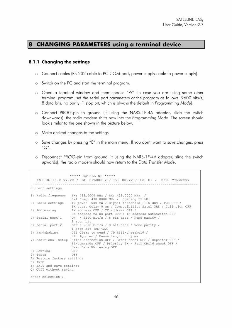
SATELLINE-EASy
User Guide, Version 2.7
46
8 CHANGING PARAMETERS using a terminal device
8.1.1 Changing the settings
o Connect cables (RS-232 cable to PC COM-port, power supply cable to power supply).
o Switch on the PC and start the terminal program.
o Open a terminal window and then choose ”Pr” (in case you are using some other terminal program, set the serial port parameters of the program as follows: 9600 bits/s, 8 data bits, no parity, 1 stop bit, which is always the default in Programming Mode).
o Connect PROG-pin to ground (if using the NARS-1F-4A adapter, slide the switch downwards), the radio modem shifts now into the Programming Mode. The screen should look similar to the one shown in the picture below.
o Make desired changes to the settings.
o Save changes by pressing ”E” in the main menu. If you don’t want to save changes, press ”Q”.
o Disconnect PROG-pin from ground (if using the NARS-1F-4A adapter, slide the switch upwards), the radio modem should now return to the Data Transfer Mode.
***** SATELLINE *****
FW: 06.16.x.xx.xx / HW: SPL0005x / PV: 00.xx / IM: 01 / S/N: YYMMxxxx
----------------------------------------------------------------------------------- Current settings
----------------
1) Radio frequency TX: 438.0000 MHz / RX: 438.0000 MHz /
Ref freq: 438.0000 MHz / Spacing 25 kHz
2) Radio settings Tx power 1000 mW / Signal threshold -115 dBm / FCS OFF /
TX start delay 0 ms / Compatibility Satel 3AS / Call sign OFF
3) Addressing RX address OFF / TX address OFF /
RX address to RS port OFF / TX address autoswitch OFF
4) Serial port 1 ON / 9600 bit/s / 8 bit data / None parity /
1 stop bit
5) Serial port 2 OFF / 9600 bit/s / 8 bit data / None parity /
1 stop bit (RS-422)
6) Handshaking CTS Clear to send / CD RSSI-threshold /
RTS Ignored / Pause length 3 bytes
7) Additional setup Error correction OFF / Error check OFF / Repeater OFF /
SL-commands OFF / Priority TX / Full CRC16 check OFF /
User Data Whitening OFF
8) Routing OFF
9) Tests OFF
A) Restore factory settings
B) INFO
E) EXIT and save settings
Q) QUIT without saving
Enter selection >
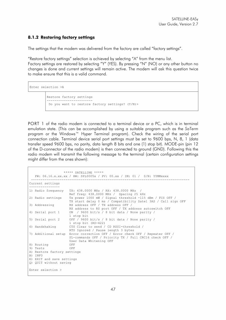
SATELLINE-EASy
User Guide, Version 2.7
47
8.1.2 Restoring factory settings
The settings that the modem was delivered from the factory are called “factory settings”. “Restore factory settings” selection is achieved by selecting “A” from the menu list. Factory settings are restored by selecting ”Y” (YES). By pressing “N” (NO) or any other button no changes is done and current settings will remain active. The modem will ask this question twice to make ensure that this is a valid command.
Enter selection >A
Restore factory settings
------------------------
Do you want to restore factory settings? (Y/N)>
PORT 1 of the radio modem is connected to a terminal device or a PC, which is in terminal emulation state. (This can be accomplished by using a suitable program such as the SaTerm program or the Windows™ Hyper Terminal program). Check the wiring of the serial port connection cable. Terminal device serial port settings must be set to 9600 bps, N, 8, 1 (data transfer speed 9600 bps, no parity, data length 8 bits and one (1) stop bit). MODE-pin (pin 12 of the D-connector of the radio modem) is then connected to ground (GND). Following this the radio modem will transmit the following message to the terminal (certain configuration settings might differ from the ones shown): ***** SATELLINE *****
FW: 06.16.x.xx.xx / HW: SPL0005x / PV: 00.xx / IM: 01 / S/N: YYMMxxxx
-----------------------------------------------------------------------------------
Current settings
----------------
1) Radio frequency TX: 438.0000 MHz / RX: 438.0000 MHz /
Ref freq: 438.0000 MHz / Spacing 25 kHz
2) Radio settings Tx power 1000 mW / Signal threshold -115 dBm / FCS OFF /
TX start delay 0 ms / Compatibility Satel 3AS / Call sign OFF
3) Addressing RX address OFF / TX address OFF /
RX address to RS port OFF / TX address autoswitch OFF
4) Serial port 1 ON / 9600 bit/s / 8 bit data / None parity /
1 stop bit
5) Serial port 2 OFF / 9600 bit/s / 8 bit data / None parity /
1 stop bit (RS-422)
6) Handshaking CTS Clear to send / CD RSSI-threshold /
RTS Ignored / Pause length 3 bytes
7) Additional setup Error correction OFF / Error check OFF / Repeater OFF /
SL-commands OFF / Priority TX / Full CRC16 check OFF /
User Data Whitening OFF
8) Routing OFF
9) Tests OFF
A) Restore factory settings
B) INFO
E) EXIT and save settings
Q) QUIT without saving
Enter selection >
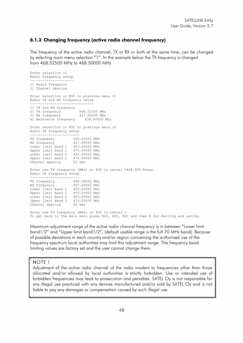
SATELLINE-EASy
User Guide, Version 2.7
48
8.1.3 Changing frequency (active radio channel frequency)
The frequency of the active radio channel, TX or RX or both at the same time, can be changed by selecting main menu selection ”1”. In the example below the TX frequency is changed from 468.52500 MHz to 468.50000 MHz Enter selection >1
Radio frequency setup
---------------------
1) Radio frequency
2) Channel spacing
Enter selection or ESC to previous menu >1
Radio TX and RX frequency setup
-------------------------------
1) TX and RX frequency
2) TX frequency 468.52500 MHz
3) RX frequency 437.00000 MHz
4) Reference frequency 438.00000 MHz
Enter selection or ESC to previous menu >2
Radio TX frequency setup
------------------------
TX frequency 468.52500 MHz
RX frequency 437.00000 MHz
Lower limit band 1 403.00000 MHz
Upper limit band 1 473.00000 MHz
Lower limit band 2 403.00000 MHz
Upper limit band 2 473.00000 MHz
Channel spacing 25 kHz
Enter new TX frequency (MHz) or ESC to cancel >468.500 Enter
Radio TX frequency setup
------------------------
TX frequency 468.50000 MHz
RX frequency 437.00000 MHz
Lower limit band 1 403.00000 MHz
Upper limit band 1 473.00000 MHz
Lower limit band 2 403.00000 MHz
Upper limit band 2 473.00000 MHz
Channel spacing 25 kHz
Enter new TX frequency (MHz) or ESC to cancel >
To get back to the main menu press ESC, ESC, ESC and then E for Exiting and saving.
Maximum adjustment range of the active radio channel frequency is in between “Lower limit band1/2” and “Upper limit band1/2”, (default usable range is the full 70 MHz band). Because of possible deviations in each country and/or region concerning the authorised use of the frequency spectrum local authorities may limit this adjustment range. The frequency band limiting values are factory set and the user cannot change them.
NNOTE ! Adjustment of the active radio channel of the radio modem to frequencies other than those allocated and/or allowed by local authorities is strictly forbidden. Use or intended use of forbidden frequencies may lead to prosecution and penalties. SATEL Oy is not responsible for any illegal use practiced with any devices manufactured and/or sold by SATEL Oy and is not liable to pay any damages or compensation caused by such illegal use.

SATELLINE-EASy
User Guide, Version 2.7
49
8.1.4 Changing Reference frequency
The Reference frequency (also known as “Center frequency”) defines the starting point, which is used by the specific SL-command to calculate the channels aabove or bbelow the Reference frequency. The calculation is based on the selected channel spacing. The Reference frequency must be in between the upper/lower band limits.
Number 1 is pressed in the Main menu.
Enter selection >1
Radio frequency setup
---------------------
1) Radio frequency
2) Channel spacing
Enter selection or ESC to previous menu >1
Radio TX and RX frequency setup
-------------------------------
1) TX and RX frequency
2) TX frequency 468.50000 MHz
3) RX frequency 437.00000 MHz
4) Reference frequency 438.00000 MHz
Enter selection or ESC to previous menu >4
Radio reference frequency setup
-------------------------------
Reference frequency 438.00000 MHz
Lower limit band 1 403.00000 MHz
Upper limit band 1 473.00000 MHz
Lower limit band 2 403.00000 MHz
Upper limit band 2 473.00000 MHz
Enter new frequency (MHz) or ESC to cancel >460.000 Enter
Reference frequency 460.00000 MHz
Lower limit band 1 403.00000 MHz
Upper limit band 1 473.00000 MHz
Lower limit band 2 403.00000 MHz
Upper limit band 2 473.00000 MHz
Enter new frequency (MHz) or ESC to cancel >
To get back to the main menu press ESC, ESC, ESC and then E for Exiting and saving.
8.1.5 Changing Channel spacing
The module can be set to different channel spacing. The values are: 12.5, 20 and 25 kHz. Number 1 is pressed in the Main menu.
Radio frequency setup
---------------------
1) Radio frequency
2) Channel spacing 25 kHz
Enter selection or ESC to previous menu >2
Channel spacing
---------------
1) 12,5 kHz
2) 20 kHz
3) 25 kHz
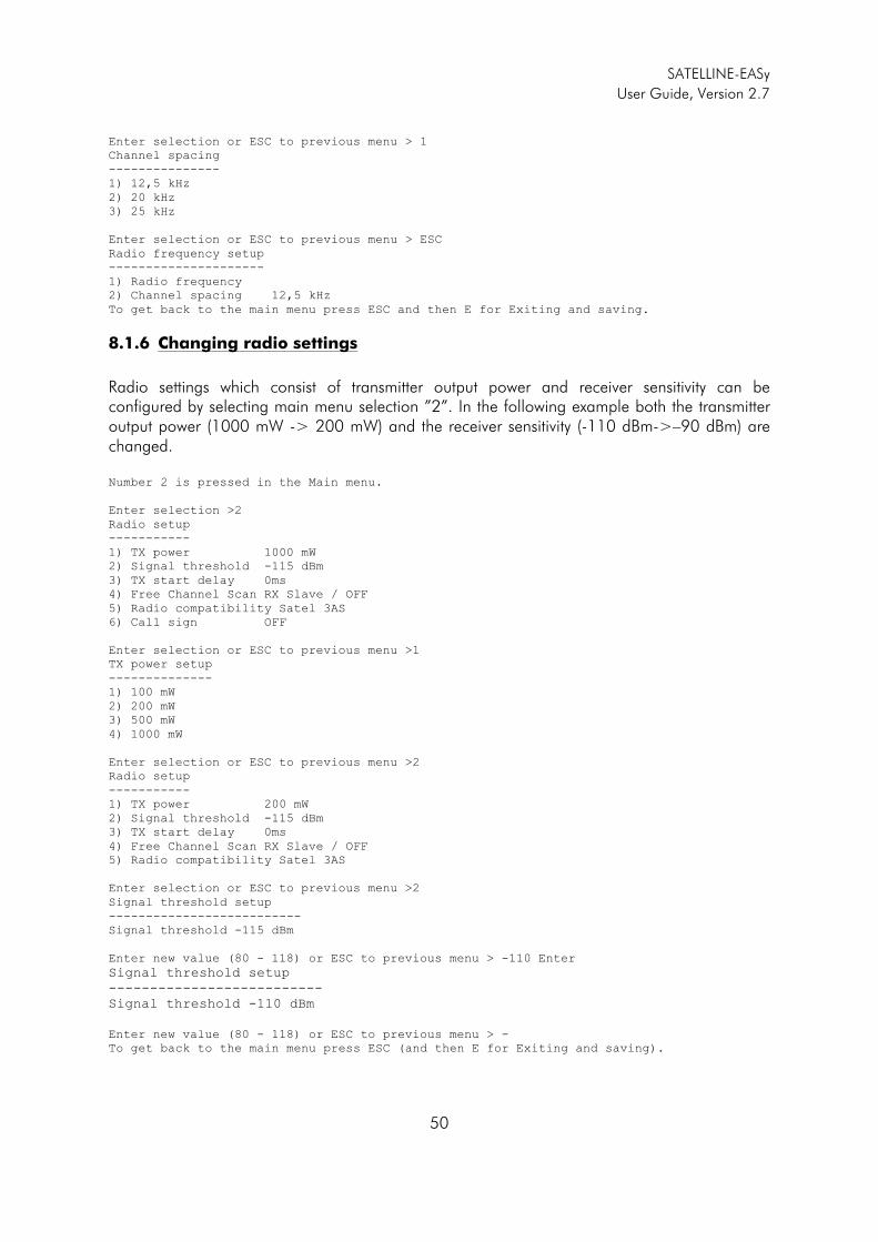
SATELLINE-EASy
User Guide, Version 2.7
50
Enter selection or ESC to previous menu > 1
Channel spacing
---------------
1) 12,5 kHz
2) 20 kHz
3) 25 kHz
Enter selection or ESC to previous menu > ESC
Radio frequency setup
---------------------
1) Radio frequency
2) Channel spacing 12,5 kHz
To get back to the main menu press ESC and then E for Exiting and saving.
8.1.6 Changing radio settings
Radio settings which consist of transmitter output power and receiver sensitivity can be configured by selecting main menu selection ”2”. In the following example both the transmitter output power (1000 mW -> 200 mW) and the receiver sensitivity (-110 dBm->–90 dBm) are changed. Number 2 is pressed in the Main menu.
Enter selection >2
Radio setup
-----------
1) TX power 1000 mW
2) Signal threshold -115 dBm
3) TX start delay 0ms
4) Free Channel Scan RX Slave / OFF
5) Radio compatibility Satel 3AS
6) Call sign OFF
Enter selection or ESC to previous menu >1 TX power setup
--------------
1) 100 mW
2) 200 mW
3) 500 mW
4) 1000 mW
Enter selection or ESC to previous menu >2
Radio setup
-----------
1) TX power 200 mW
2) Signal threshold -115 dBm
3) TX start delay 0ms
4) Free Channel Scan RX Slave / OFF
5) Radio compatibility Satel 3AS
Enter selection or ESC to previous menu >2 Signal threshold setup
--------------------------
Signal threshold -115 dBm
Enter new value (80 - 118) or ESC to previous menu > -110 Enter
Signal threshold setup
--------------------------
Signal threshold -110 dBm
Enter new value (80 - 118) or ESC to previous menu > -
To get back to the main menu press ESC (and then E for Exiting and saving).
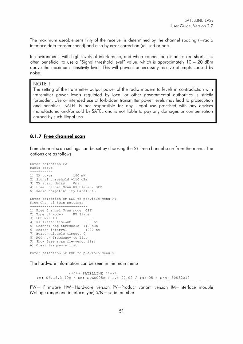
SATELLINE-EASy
User Guide, Version 2.7
51
The maximum useable sensitivity of the receiver is determined by the channel spacing (=radio interface data transfer speed) and also by error correction (utilised or not). In environments with high levels of interference, and when connection distances are short, it is often beneficial to use a ”Signal threshold level” value, which is approximately 10 – 20 dBm above the maximum sensitivity level. This will prevent unnecessary receive attempts caused by noise.
8.1.7 Free channel scan
Free channel scan settings can be set by choosing the 2) Free channel scan from the menu. The options are as follows: Enter selection >2
Radio setup
-----------
1) TX power 100 mW
2) Signal threshold -110 dBm
3) TX start delay 0ms
4) Free Channel Scan RX Slave / OFF
5) Radio compatibility Satel 3AS
Enter selection or ESC to previous menu >4
Free Channel Scan settings
----------------------------
1) Free Channel Scan mode OFF
2) Type of modem RX Slave
3) FCS Net ID 0000
4) RX listen timeout 500 ms
5) Channel hop threshold -110 dBm
6) Beacon interval 1000 ms
7) Beacon disable timeout 0
8) Add new frequency to list
9) Show free scan frequency list
A) Clear frequency list
Enter selection or ESC to previous menu >
The hardware information can be seen in the main menu ***** SATELLINE *****
FW: 06.16.3.40e / HW: SPL0005c / PV: 00.02 / IM: 05 / S/N: 30032010
-------------------------------------------------------------------------------
FW= Firmware HW=Hardware version PV=Product variant version IM=Interface module (Voltage range and interface type) S/N= serial number.
NNOTE ! The setting of the transmitter output power of the radio modem to levels in contradiction with transmitter power levels regulated by local or other governmental authorities is strictly forbidden. Use or intended use of forbidden transmitter power levels may lead to prosecution and penalties. SATEL is not responsible for any illegal use practised with any devices manufactured and/or sold by SATEL and is not liable to pay any damages or compensation caused by such illegal use.
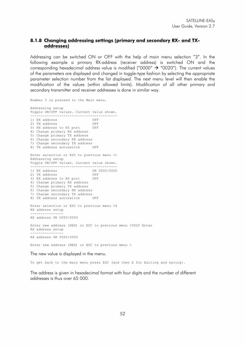
SATELLINE-EASy
User Guide, Version 2.7
52
8.1.8 Changing addressing settings (primary and secondary RX- and TX-
addresses)
Addressing can be switched ON or OFF with the help of main menu selection ”3”. In the following example a primary RX-address (receiver address) is switched ON and the corresponding hexadecimal address value is modified (”0000” � ”0020”). The current values of the parameters are displayed and changed in toggle-type fashion by selecting the appropriate parameter selection number from the list displayed. The next menu level will then enable the modification of the values (within allowed limits). Modification of all other primary and secondary transmitter and receiver addresses is done in similar way. Number 3 is pressed in the Main menu.
Addressing setup
Toggle ON/OFF values. Current value shown.
------------------------------------------
1) RX address OFF
2) TX address OFF
3) RX address to RS port OFF
4) Change primary RX address
5) Change primary TX address
6) Change secondary RX address
7) Change secondary TX address
8) TX address autoswitch OFF
Enter selection or ESC to previous menu >1
Addressing setup
Toggle ON/OFF values. Current value shown.
------------------------------------------
1) RX address ON 0000/0000
2) TX address OFF
3) RX address to RS port OFF
4) Change primary RX address
5) Change primary TX address
6) Change secondary RX address
7) Change secondary TX address
8) TX address autoswitch OFF
Enter selection or ESC to previous menu >4 RX address setup
----------------
RX address ON 0000/0000
Enter new address (HEX) or ESC to previous menu >0020 Enter RX address setup
----------------
RX address ON 0020/0000
Enter new address (HEX) or ESC to previous menu >
The new value is displayed in the menu. To get back to the main menu press ESC (and then E for Exiting and saving).
The address is given in hexadecimal format with four digits and the number of different addresses is thus over 65 000.
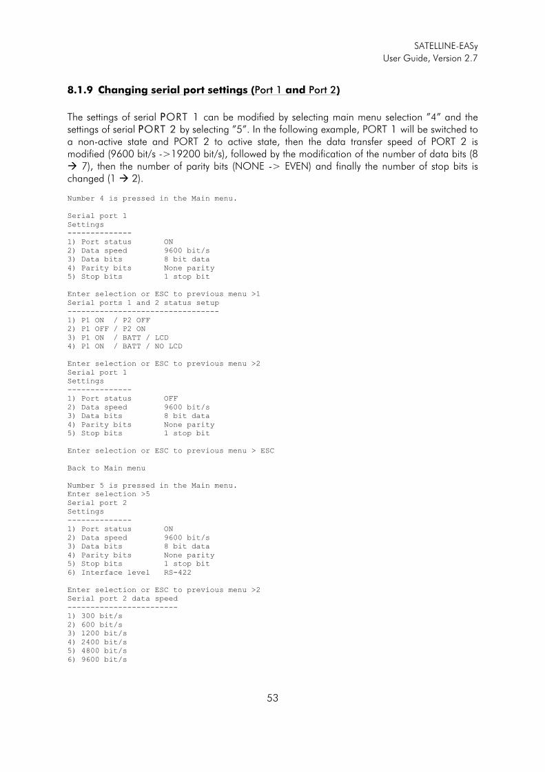
SATELLINE-EASy
User Guide, Version 2.7
53
8.1.9 Changing serial port settings (Port 1 and Port 2)
The settings of serial PPORT 1 can be modified by selecting main menu selection ”4” and the settings of serial PPORT 2 by selecting ”5”. In the following example, PORT 1 will be switched to a non-active state and PORT 2 to active state, then the data transfer speed of PORT 2 is modified (9600 bit/s ->19200 bit/s), followed by the modification of the number of data bits (8 � 7), then the number of parity bits (NONE -> EVEN) and finally the number of stop bits is changed (1 � 2). Number 4 is pressed in the Main menu.
Serial port 1
Settings
--------------
1) Port status ON
2) Data speed 9600 bit/s
3) Data bits 8 bit data
4) Parity bits None parity
5) Stop bits 1 stop bit
Enter selection or ESC to previous menu >1
Serial ports 1 and 2 status setup
---------------------------------
1) P1 ON / P2 OFF
2) P1 OFF / P2 ON
3) P1 ON / BATT / LCD
4) P1 ON / BATT / NO LCD
Enter selection or ESC to previous menu >2
Serial port 1
Settings
--------------
1) Port status OFF
2) Data speed 9600 bit/s
3) Data bits 8 bit data
4) Parity bits None parity
5) Stop bits 1 stop bit
Enter selection or ESC to previous menu > ESC
Back to Main menu
Number 5 is pressed in the Main menu.
Enter selection >5
Serial port 2
Settings
--------------
1) Port status ON
2) Data speed 9600 bit/s
3) Data bits 8 bit data
4) Parity bits None parity
5) Stop bits 1 stop bit
6) Interface level RS-422
Enter selection or ESC to previous menu >2
Serial port 2 data speed
------------------------
1) 300 bit/s
2) 600 bit/s
3) 1200 bit/s
4) 2400 bit/s
5) 4800 bit/s
6) 9600 bit/s
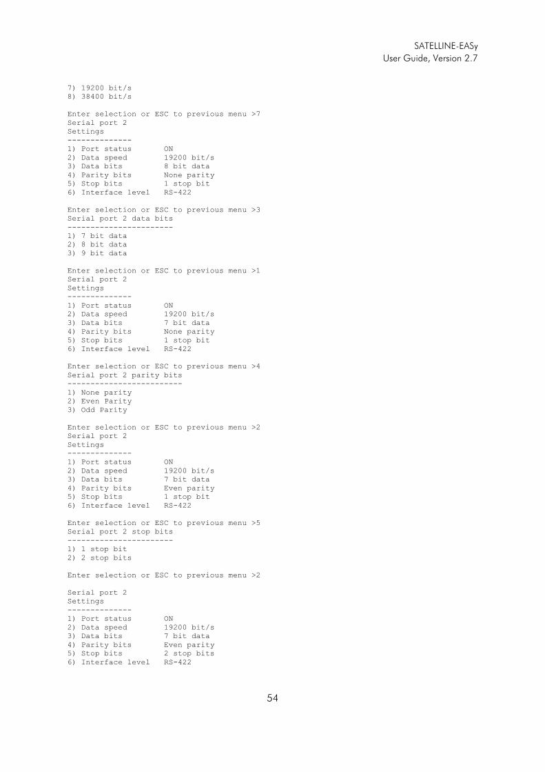
SATELLINE-EASy
User Guide, Version 2.7
54
7) 19200 bit/s
8) 38400 bit/s
Enter selection or ESC to previous menu >7
Serial port 2
Settings
--------------
1) Port status ON
2) Data speed 19200 bit/s
3) Data bits 8 bit data
4) Parity bits None parity
5) Stop bits 1 stop bit
6) Interface level RS-422
Enter selection or ESC to previous menu >3
Serial port 2 data bits
-----------------------
1) 7 bit data
2) 8 bit data
3) 9 bit data
Enter selection or ESC to previous menu >1
Serial port 2
Settings
--------------
1) Port status ON
2) Data speed 19200 bit/s
3) Data bits 7 bit data
4) Parity bits None parity
5) Stop bits 1 stop bit
6) Interface level RS-422
Enter selection or ESC to previous menu >4
Serial port 2 parity bits
-------------------------
1) None parity
2) Even Parity
3) Odd Parity
Enter selection or ESC to previous menu >2
Serial port 2
Settings
--------------
1) Port status ON
2) Data speed 19200 bit/s
3) Data bits 7 bit data
4) Parity bits Even parity
5) Stop bits 1 stop bit
6) Interface level RS-422
Enter selection or ESC to previous menu >5
Serial port 2 stop bits
-----------------------
1) 1 stop bit
2) 2 stop bits
Enter selection or ESC to previous menu >2
Serial port 2
Settings
--------------
1) Port status ON
2) Data speed 19200 bit/s
3) Data bits 7 bit data
4) Parity bits Even parity
5) Stop bits 2 stop bits
6) Interface level RS-422
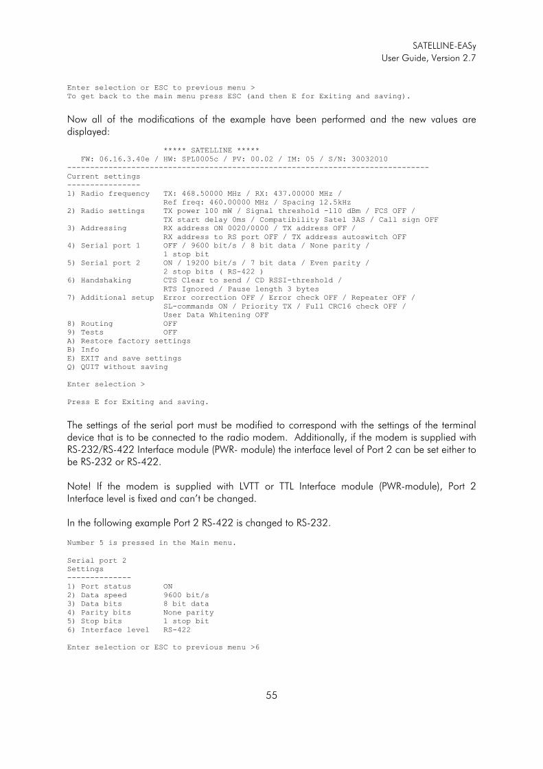
SATELLINE-EASy
User Guide, Version 2.7
55
Enter selection or ESC to previous menu >
To get back to the main menu press ESC (and then E for Exiting and saving).
Now all of the modifications of the example have been performed and the new values are displayed:
***** SATELLINE *****
FW: 06.16.3.40e / HW: SPL0005c / PV: 00.02 / IM: 05 / S/N: 30032010
-------------------------------------------------------------------------------
Current settings
----------------
1) Radio frequency TX: 468.50000 MHz / RX: 437.00000 MHz /
Ref freq: 460.00000 MHz / Spacing 12.5kHz
2) Radio settings TX power 100 mW / Signal threshold -110 dBm / FCS OFF /
TX start delay 0ms / Compatibility Satel 3AS / Call sign OFF
3) Addressing RX address ON 0020/0000 / TX address OFF /
RX address to RS port OFF / TX address autoswitch OFF
4) Serial port 1 OFF / 9600 bit/s / 8 bit data / None parity /
1 stop bit
5) Serial port 2 ON / 19200 bit/s / 7 bit data / Even parity /
2 stop bits ( RS-422 )
6) Handshaking CTS Clear to send / CD RSSI-threshold /
RTS Ignored / Pause length 3 bytes
7) Additional setup Error correction OFF / Error check OFF / Repeater OFF /
SL-commands ON / Priority TX / Full CRC16 check OFF /
User Data Whitening OFF
8) Routing OFF
9) Tests OFF
A) Restore factory settings
B) Info
E) EXIT and save settings
Q) QUIT without saving
Enter selection >
Press E for Exiting and saving.
The settings of the serial port must be modified to correspond with the settings of the terminal device that is to be connected to the radio modem. Additionally, if the modem is supplied with RS-232/RS-422 Interface module (PWR- module) the interface level of Port 2 can be set either to be RS-232 or RS-422. Note! If the modem is supplied with LVTT or TTL Interface module (PWR-module), Port 2 Interface level is fixed and can’t be changed. In the following example Port 2 RS-422 is changed to RS-232.
Number 5 is pressed in the Main menu.
Serial port 2
Settings
--------------
1) Port status ON
2) Data speed 9600 bit/s
3) Data bits 8 bit data
4) Parity bits None parity
5) Stop bits 1 stop bit
6) Interface level RS-422
Enter selection or ESC to previous menu >6
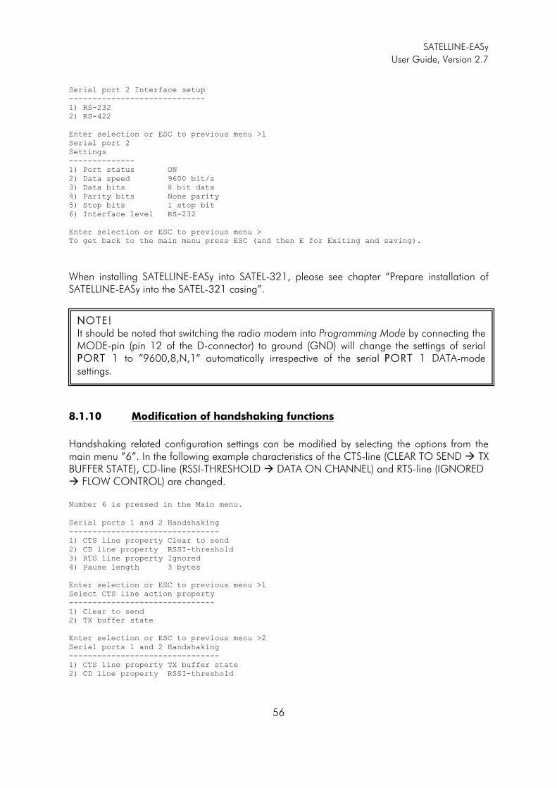
SATELLINE-EASy
User Guide, Version 2.7
56
Serial port 2 Interface setup
-----------------------------
1) RS-232
2) RS-422
Enter selection or ESC to previous menu >1
Serial port 2
Settings
--------------
1) Port status ON
2) Data speed 9600 bit/s
3) Data bits 8 bit data
4) Parity bits None parity
5) Stop bits 1 stop bit
6) Interface level RS-232
Enter selection or ESC to previous menu > To get back to the main menu press ESC (and then E for Exiting and saving).
When installing SATELLINE-EASy into SATEL-321, please see chapter “Prepare installation of SATELLINE-EASy into the SATEL-321 casing”.
8.1.10 Modification of handshaking functions
Handshaking related configuration settings can be modified by selecting the options from the main menu ”6”. In the following example characteristics of the CTS-line (CLEAR TO SEND � TX BUFFER STATE), CD-line (RSSI-THRESHOLD � DATA ON CHANNEL) and RTS-line (IGNORED � FLOW CONTROL) are changed. Number 6 is pressed in the Main menu.
Serial ports 1 and 2 Handshaking
--------------------------------
1) CTS line property Clear to send
2) CD line property RSSI-threshold
3) RTS line property Ignored
4) Pause length 3 bytes
Enter selection or ESC to previous menu >1
Select CTS line action property
-------------------------------
1) Clear to send
2) TX buffer state
Enter selection or ESC to previous menu >2
Serial ports 1 and 2 Handshaking
--------------------------------
1) CTS line property TX buffer state
2) CD line property RSSI-threshold
NNOTE! It should be noted that switching the radio modem into Programming Mode by connecting the MODE-pin (pin 12 of the D-connector) to ground (GND) will change the settings of serial PPORT 1 to ”9600,8,N,1” automatically irrespective of the serial PPORT 1 DATA-mode settings.
SATELLINE-EASy
User Guide, Version 2.7
57
3) RTS line property Ignored
4) Pause length 3 bytes
Enter selection or ESC to previous menu >2
Select CD line action property
------------------------------
1) RSSI-threshold
2) Data on channel
3) Always ON
Enter selection or ESC to previous menu >2
Serial ports 1 and 2 Handshaking
--------------------------------
1) CTS line property TX buffer state
2) CD line property Data on channel
3) RTS line property Ignored
4) Pause length 3 bytes
Enter selection or ESC to previous menu >3
Select RTS line action property
-------------------------------
1) Ignored
2) Flow control
3) Reception Control
Enter selection or ESC to previous menu >2
Serial ports 1 and 2 Handshaking
--------------------------------
1) CTS line property TX buffer state
2) CD line property Data on channel
3) RTS line property Flow control
4) Pause length 3 bytes
Enter selection or ESC to previous menu >
To get back to the main menu press ESC (and then E for Exiting and saving).
Now all of the modifications of the example have been performed and the new values are displayed on the menu as follows: ***** SATELLINE *****
FW: 06.16.3.42 / HW: SPL0005b / PV: 00.04 / IM: 01 /
-------------------------------------------------------------------------------
Current settings
----------------
1) Radio frequency TX: 438.00000 MHz / RX: 450.00000 MHz /
Ref freq: 438.00000 MHz / Spacing 20kHz
2) Radio settings TX power 1000 mW / Signal threshold -118 dBm / FCS OFF /
TX start delay 0ms / Compatibility Satel 3AS / Call sign OFF
3) Addressing RX address OFF / TX address OFF /
RX address to RS port OFF / TX address autoswitch OFF
4) Serial port 1 OFF / 9600 bit/s / 8 bit data / None parity /
1 stop bit
5) Serial port 2 ON / 9600 bit/s / 8 bit data / None parity /
1 stop bit ( RS-232 )
6) Handshaking CTS TX buffer state / CD Data on channel /
RTS Flow control / Pause length 3 bytes
7) Additional setup Error correction OFF / Error check OFF / Repeater OFF /
SL-commands ON / Priority TX / Full CRC16 check OFF /
User Data Whitening OFF
8) Routing OFF
9) Tests OFF
A) Restore factory settings
B) Info
E) EXIT and save settings
Q) QUIT without saving
SATELLINE-EASy
User Guide, Version 2.7
58
Enter selection >
8.1.11 Special functions
Special functions are modified by selecting from the main menu selection ”7”. The current values of the parameters are displayed and can be modified in toggle-type fashion by choosing the appropriate parameter selection number from the list displayed. The next menu level will then enable the modification of the values (within allowed limits).
Number 7 is pressed in the Main menu.
Additional setup
Toggle ON/OFF values. Current value shown.
------------------------------------------
1) Error correction OFF
2) Error check OFF
3) Repeater OFF
4) SL-commands ON
5) Priority TX
6) Full CRC16 check OFF
7) User Data Whitening OFF
Enter selection or ESC to previous menu >
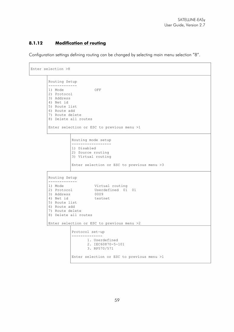
SATELLINE-EASy
User Guide, Version 2.7
59
8.1.12 Modification of routing
Configuration settings defining routing can be changed by selecting main menu selection ”8”.
Enter selection >8
Routing Setup
-------------
1) Mode OFF
2) Protocol
3) Address
4) Net id
5) Route list
6) Route add
7) Route delete
8) Delete all routes
Enter selection or ESC to previous menu >1
Routing mode setup
------------------
1) Disabled
2) Source routing
3) Virtual routing
Enter selection or ESC to previous menu >3
Routing Setup
-------------
1) Mode Virtual routing
2) Protocol Userdefined 01 01
3) Address 0009
4) Net id testnet
5) Route list
6) Route add
7) Route delete
8) Delete all routes
Enter selection or ESC to previous menu >2
Protocol set-up
--------------
1. Userdefined
2. IEC60870-5-101
3. RP570/571
Enter selection or ESC to previous menu >1
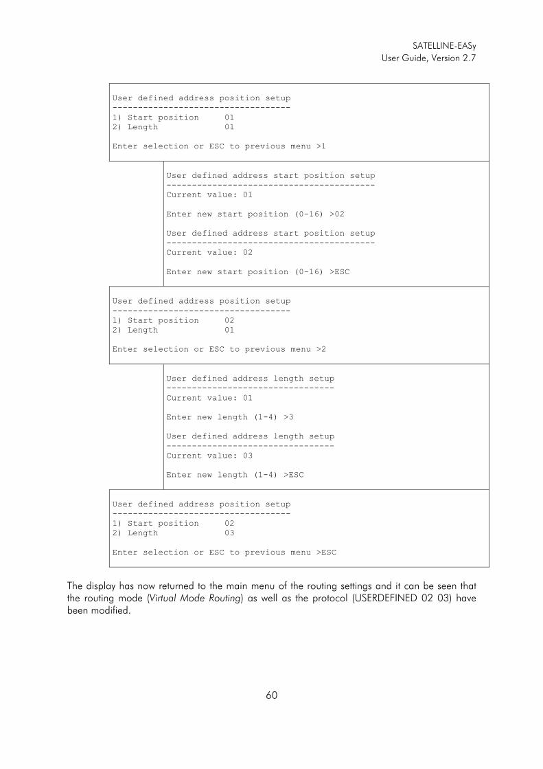
SATELLINE-EASy
User Guide, Version 2.7
60
User defined address position setup
-----------------------------------
1) Start position 01
2) Length 01
Enter selection or ESC to previous menu >1
User defined address start position setup
-----------------------------------------
Current value: 01
Enter new start position (0-16) >02
User defined address start position setup
-----------------------------------------
Current value: 02
Enter new start position (0-16) >ESC
User defined address position setup
-----------------------------------
1) Start position 02
2) Length 01
Enter selection or ESC to previous menu >2
User defined address length setup
---------------------------------
Current value: 01
Enter new length (1-4) >3
User defined address length setup
---------------------------------
Current value: 03
Enter new length (1-4) >ESC
User defined address position setup
-----------------------------------
1) Start position 02
2) Length 03
Enter selection or ESC to previous menu >ESC
The display has now returned to the main menu of the routing settings and it can be seen that the routing mode (Virtual Mode Routing) as well as the protocol (USERDEFINED 02 03) have been modified.
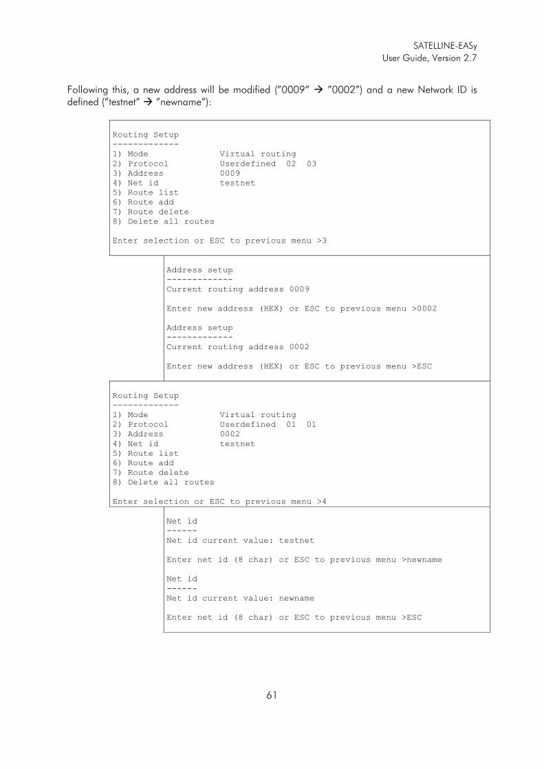
SATELLINE-EASy
User Guide, Version 2.7
61
Following this, a new address will be modified (”0009” � ”0002”) and a new Network ID is defined (”testnet” � ”newname”):
Routing Setup
-------------
1) Mode Virtual routing
2) Protocol Userdefined 02 03
3) Address 0009
4) Net id testnet
5) Route list
6) Route add
7) Route delete
8) Delete all routes
Enter selection or ESC to previous menu >3
Address setup
-------------
Current routing address 0009
Enter new address (HEX) or ESC to previous menu >0002
Address setup
-------------
Current routing address 0002
Enter new address (HEX) or ESC to previous menu >ESC
Routing Setup
-------------
1) Mode Virtual routing
2) Protocol Userdefined 01 01
3) Address 0002
4) Net id testnet
5) Route list
6) Route add
7) Route delete
8) Delete all routes
Enter selection or ESC to previous menu >4
Net id
------
Net id current value: testnet
Enter net id (8 char) or ESC to previous menu >newname
Net id
------
Net id current value: newname
Enter net id (8 char) or ESC to previous menu >ESC
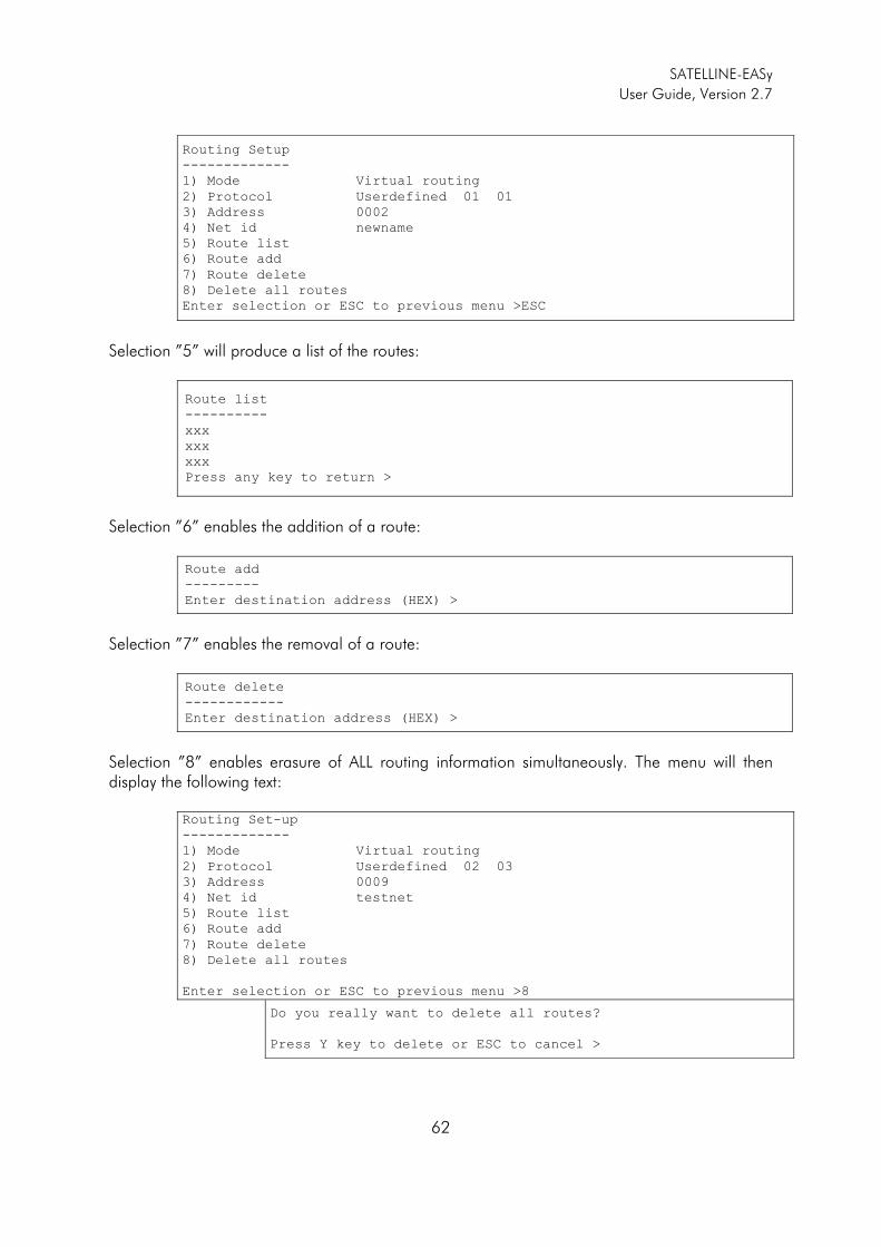
SATELLINE-EASy
User Guide, Version 2.7
62
Routing Setup
-------------
1) Mode Virtual routing
2) Protocol Userdefined 01 01
3) Address 0002
4) Net id newname
5) Route list
6) Route add
7) Route delete
8) Delete all routes
Enter selection or ESC to previous menu >ESC
Selection ”5” will produce a list of the routes:
Route list
----------
xxx
xxx
xxx
Press any key to return >
Selection ”6” enables the addition of a route:
Route add
---------
Enter destination address (HEX) >
Selection ”7” enables the removal of a route:
Route delete
------------
Enter destination address (HEX) >
Selection ”8” enables erasure of ALL routing information simultaneously. The menu will then display the following text: Routing Set-up
-------------
1) Mode Virtual routing
2) Protocol Userdefined 02 03
3) Address 0009
4) Net id testnet
5) Route list
6) Route add 7) Route delete
8) Delete all routes
Enter selection or ESC to previous menu >8
Do you really want to delete all routes?
Press Y key to delete or ESC to cancel >
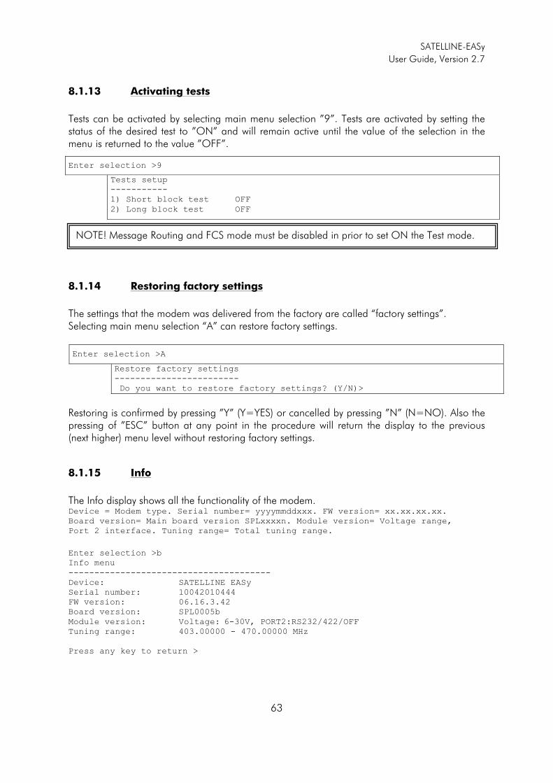
SATELLINE-EASy
User Guide, Version 2.7
63
8.1.13 Activating tests
Tests can be activated by selecting main menu selection ”9”. Tests are activated by setting the status of the desired test to ”ON” and will remain active until the value of the selection in the menu is returned to the value ”OFF”.
8.1.14 Restoring factory settings
The settings that the modem was delivered from the factory are called “factory settings”. Selecting main menu selection “A” can restore factory settings.
Enter selection >A
Restore factory settings
------------------------
Do you want to restore factory settings? (Y/N)>
Restoring is confirmed by pressing ”Y” (Y=YES) or cancelled by pressing ”N” (N=NO). Also the pressing of ”ESC” button at any point in the procedure will return the display to the previous (next higher) menu level without restoring factory settings.
8.1.15 Info
The Info display shows all the functionality of the modem. Device = Modem type. Serial number= yyyymmddxxx. FW version= xx.xx.xx.xx.
Board version= Main board version SPLxxxxn. Module version= Voltage range,
Port 2 interface. Tuning range= Total tuning range.
Enter selection >b
Info menu
---------------------------------------
Device: SATELLINE EASy
Serial number: 10042010444
FW version: 06.16.3.42
Board version: SPL0005b
Module version: Voltage: 6-30V, PORT2:RS232/422/OFF
Tuning range: 403.00000 - 470.00000 MHz
Press any key to return >
Enter selection >9
Tests setup
-----------
1) Short block test OFF
2) Long block test OFF
NOTE! Message Routing and FCS mode must be disabled in prior to set ON the Test mode.
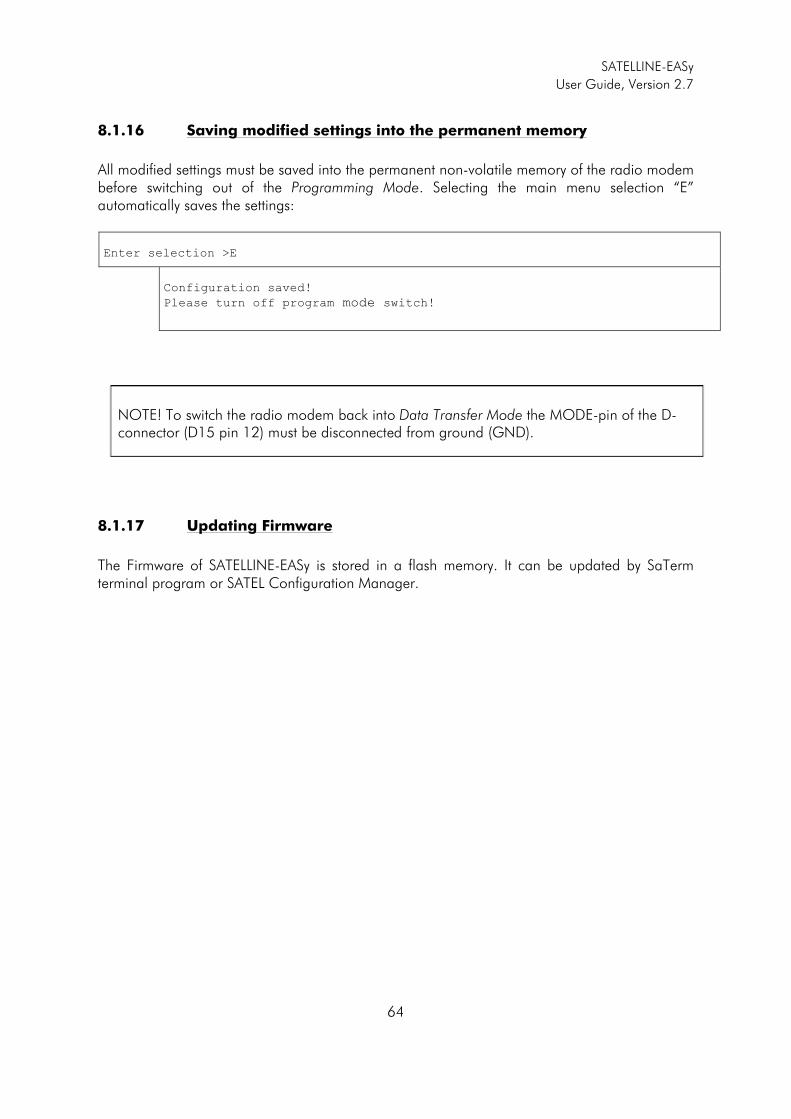
SATELLINE-EASy
User Guide, Version 2.7
64
8.1.16 Saving modified settings into the permanent memory
All modified settings must be saved into the permanent non-volatile memory of the radio modem before switching out of the Programming Mode. Selecting the main menu selection “E” automatically saves the settings:
Enter selection >E
Configuration saved!
Please turn off program mode switch!
8.1.17 Updating Firmware
The Firmware of SATELLINE-EASy is stored in a flash memory. It can be updated by SaTerm terminal program or SATEL Configuration Manager.
NOTE! To switch the radio modem back into Data Transfer Mode the MODE-pin of the D-connector (D15 pin 12) must be disconnected from ground (GND).
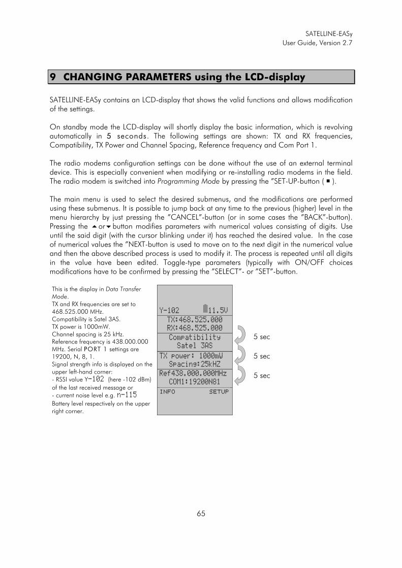
SATELLINE-EASy
User Guide, Version 2.7
65
9 CHANGING PARAMETERS using the LCD-display
SATELLINE-EASy contains an LCD-display that shows the valid functions and allows modification of the settings. On standby mode the LCD-display will shortly display the basic information, which is revolving automatically in 55 seconds. The following settings are shown: TX and RX frequencies, Compatibility, TX Power and Channel Spacing, Reference frequency and Com Port 1. The radio modems configuration settings can be done without the use of an external terminal device. This is especially convenient when modifying or re-installing radio modems in the field. The radio modem is switched into Programming Mode by pressing the ”SET-UP-button ( � ).
The main menu is used to select the desired submenus, and the modifications are performed using these submenus. It is possible to jump back at any time to the previous (higher) level in the menu hierarchy by just pressing the ”CANCEL”-button (or in some cases the ”BACK”-button). Pressing the �or�button modifies parameters with numerical values consisting of digits. Use until the said digit (with the cursor blinking under it) has reached the desired value. In the case of numerical values the ”NEXT-button is used to move on to the next digit in the numerical value and then the above described process is used to modify it. The process is repeated until all digits in the value have been edited. Toggle-type parameters (typically with ON/OFF choices modifications have to be confirmed by pressing the ”SELECT”- or ”SET”-button.
This is the display in Data Transfer Mode. TX and RX frequencies are set to 468.525.000 MHz. Compatibility is Satel 3AS. TX power is 1000mW. Channel spacing is 25 kHz. Reference frequency is 438.000.000 MHz. Serial PPORT 1 settings are 19200, N, 8, 1. Signal strength info is displayed on the upper left-hand corner: - RSSI value Y-102 (here -102 dBm)
of the last received message or - current noise level e.g. n-115
Battery level respectively on the upper right corner.
Y-102 11.5V
TX:468.525.000
RX:468.525.000
Compatibility
Satel 3AS
TX power: 1000mW
Spacing:25kHZ Ref438.000.000MHz
COM1:19200N81
INFO SETUP
5 sec
5 sec
5 sec
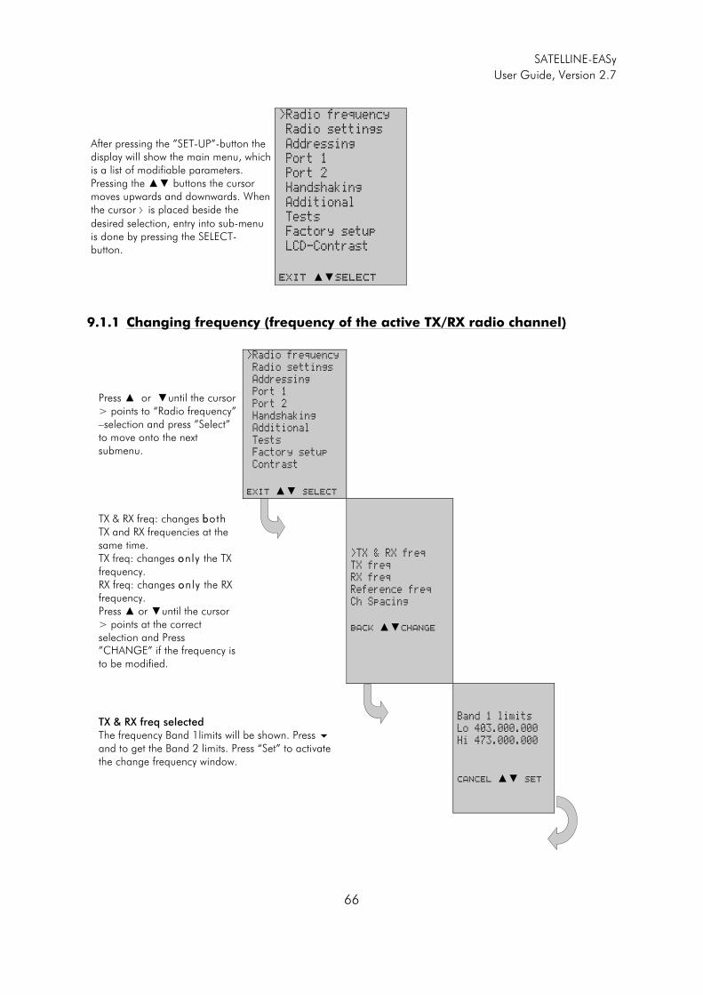
SATELLINE-EASy
User Guide, Version 2.7
66
After pressing the ”SET-UP”-button the display will show the main menu, which is a list of modifiable parameters. Pressing the �� buttons the cursor moves upwards and downwards. When the cursor > is placed beside the
desired selection, entry into sub-menu is done by pressing the SELECT- button.
>Radio frequency
Radio settings
Addressing
Port 1
Port 2
Handshaking
Additional
Tests
Factory setup
LCD-Contrast
EXIT ��Select
9.1.1 Changing frequency (frequency of the active TX/RX radio channel)
Press � or �until the cursor > points to “Radio frequency” –selection and press ”Select” to move onto the next submenu.
>Radio frequency
Radio settings
Addressing
Port 1
Port 2
Handshaking
Additional
Tests
Factory setup
Contrast
EXIT �� Select
TX & RX freq: changes bboth TX and RX frequencies at the same time. TX freq: changes oonly the TX frequency. RX freq: changes oonly the RX frequency. Press � or �until the cursor > points at the correct selection and Press ”CHANGE” if the frequency is to be modified.
>TX & RX freq
TX freq
RX freq
Reference freq
Ch Spacing
BACK ��Change
TX & RX freq selected The frequency Band 1limits will be shown. Press � and to get the Band 2 limits. Press “Set” to activate the change frequency window.
Band 1 limits
Lo 403.000.000
Hi 473.000.000
Cancel �� Set
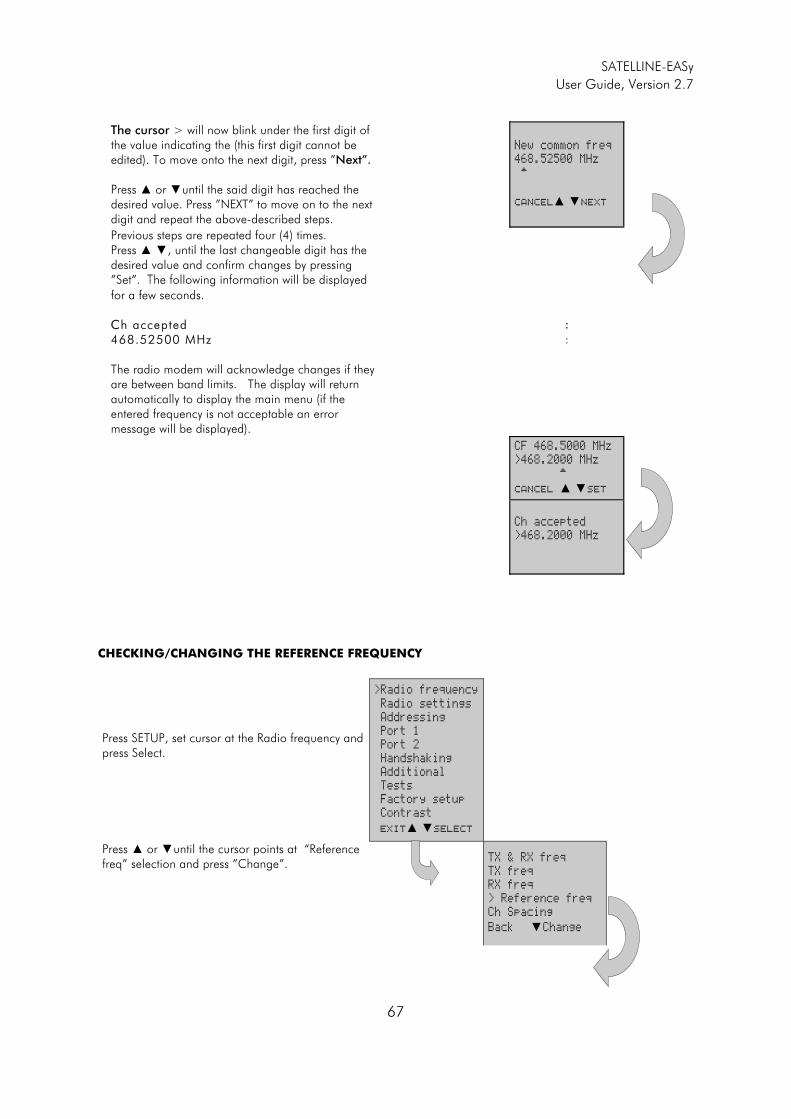
SATELLINE-EASy
User Guide, Version 2.7
67
The cursor > will now blink under the first digit of the value indicating the (this first digit cannot be edited). To move onto the next digit, press ”Next”. Press � or �until the said digit has reached the desired value. Press ”NEXT” to move on to the next digit and repeat the above-described steps.
New common freq
468.52500 MHz
^
Cancel� �Next
Previous steps are repeated four (4) times. Press � �, until the last changeable digit has the desired value and confirm changes by pressing ”Set”. The following information will be displayed
for a few seconds. CCh accepted 468.52500 MHz The radio modem will acknowledge changes if they are between band limits. The display will return automatically to display the main menu (if the entered frequency is not acceptable an error message will be displayed).
: :
CF 468.5000 MHz
>468.2000 MHz
^
CANCEL � �SET
Ch accepted
>468.2000 MHz
CHECKING/CHANGING THE REFERENCE FREQUENCY
Press SETUP, set cursor at the Radio frequency and press Select.
>Radio frequency
Radio settings
Addressing
Port 1
Port 2
Handshaking
Additional
Tests
Factory setup
Contrast
EXIT� �Select
Press � or �until the cursor points at “Reference freq” selection and press ”Change”.
TX & RX freq
TX freq
RX freq
> Reference freq
Ch Spacing
Back �Change
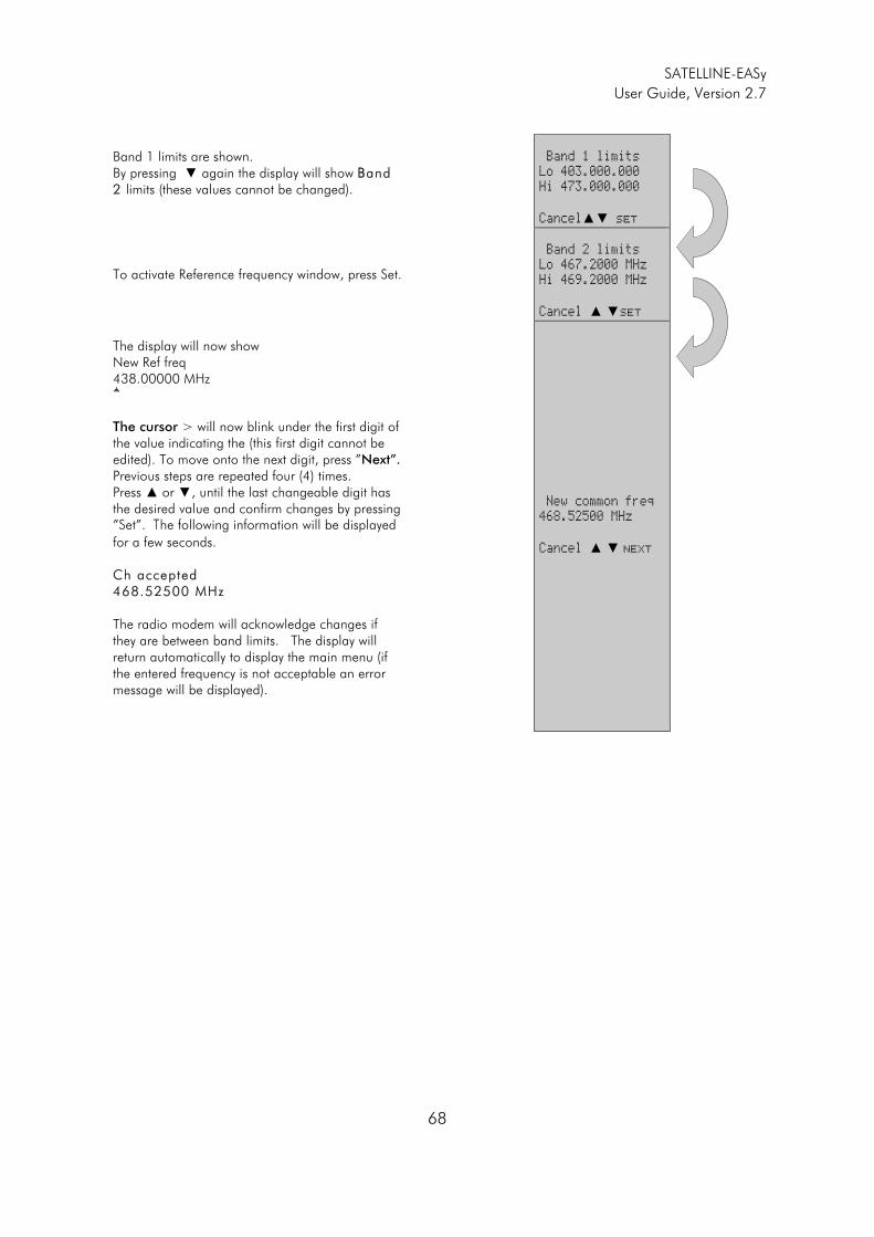
SATELLINE-EASy
User Guide, Version 2.7
68
Band 1 limits are shown. By pressing � again the display will show BBand 2 limits (these values cannot be changed).
Band 1 limits
Lo 403.000.000
Hi 473.000.000
Cancel�� Set
To activate Reference frequency window, press Set.
Band 2 limits
Lo 467.2000 MHz
Hi 469.2000 MHz
Cancel � �Set
The display will now show New Ref freq 438.00000 MHz ^
The cursor > will now blink under the first digit of the value indicating the (this first digit cannot be edited). To move onto the next digit, press ”Next”. Previous steps are repeated four (4) times. Press � or �, until the last changeable digit has the desired value and confirm changes by pressing ”Set”. The following information will be displayed
for a few seconds. Ch accepted 468.52500 MHz The radio modem will acknowledge changes if they are between band limits. The display will return automatically to display the main menu (if the entered frequency is not acceptable an error message will be displayed).
New common freq
468.52500 MHz
Cancel � � Next

SATELLINE-EASy
User Guide, Version 2.7
69
9.1.2 Changing radio settings (transmitter power and receiver sensitivity)
Press � or � until the cursor > points to “Radio settings” selection and press ”Select” to move on to the submenu.
Radio frequency
>Radio settings
Addressing
Port 1
Port 2
Handshaking
Additional
Tests
Factory setup
LCD-Contrast
Exit � �Select
Press � or � until the cursor > points to the setting to be modified and press ”Change”.
>TX level
Sig. Threshold
TX start delay
Compatibility
Call sign
Back �Change
MODIFYING TRANSMITTER OUTPUT POWER: The displayed list consists off all possible values of transmitter output power. Press � or �until the cursor > points to the desired value and press ”SET”. NNOTE: The starting position of the cursor indicates the previously set value.
100mW
200mW
500mW
>1000mW
Cancel � Set
MODIFYING RECEIVER SENSITIVITY: The displayed list consists off all possible values of receiver sensitivity. Press � or �until the cursor > points to the desired value and press ”SET”. NNOTE: The starting position of the cursor indicates the previously set value.
min
-116 dBm
> -115 dBm
-114 dBm .
.
-81 dBm
-80 dBm
max
CANCEL� � SET
MODIFYING THE TRANSMIT START DELAY: The display will show the current value of the delay. Press ”Change” to modify the value.
TX start delay
current value:
0 ms
Cancel� �Change
Press � or �until the first digit of the value has reached the desired value and then press ”NEXT” to move on to the next digit.
TX start delay
>00000 ms
^
Cancel��Next
Repeat the above described five (5) times. : :
Press � or �until the last changeable digit has the desired value and finally confirm changes by pressing ”SET”.
TX start delay
>01234 ms
^
Cancel��SET
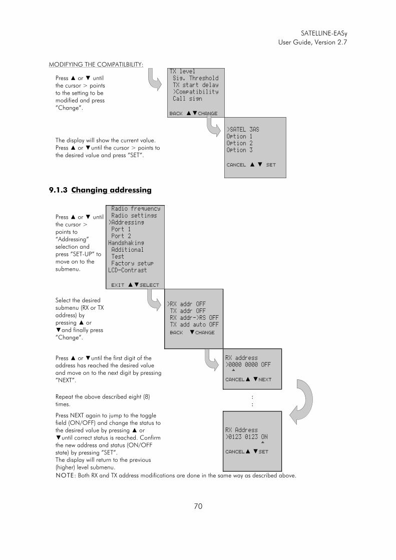
SATELLINE-EASy
User Guide, Version 2.7
70
MODIFYING THE COMPATILBILITY:
Press � or � until the cursor > points to the setting to be modified and press ”Change”.
TX level
Sig. Threshold
TX start delay
>Compatibility
Call sign
Back ��Change
The display will show the current value. Press � or �until the cursor > points to the desired value and press ”SET”.
>SATEL 3AS
Option 1
Option 2
Option 3
Cancel � � Set
9.1.3 Changing addressing
Press � or � until the cursor > points to “Addressing” selection and press ”SET-UP” to move on to the submenu.
Radio frequency
Radio settings
>Addressing
Port 1
Port 2
Handshaking
Additional
Test
Factory setup
LCD-Contrast
EXIT ��Select
Select the desired submenu (RX or TX address) by pressing � or �and finally press ”Change”.
>RX addr OFF
TX addr OFF
RX addr->RS OFF
TX add auto OFF
Back �Change
Press � or �until the first digit of the address has reached the desired value and move on to the next digit by pressing ”NEXT”.
RX address
>0000 0000 OFF
^
Cancel� �Next
Repeat the above described eight (8) times.
: :
Press NEXT again to jump to the toggle field (ON/OFF) and change the status to the desired value by pressing � or �until correct status is reached. Confirm the new address and status (ON/OFF state) by pressing ”SET”. The display will return to the previous (higher) level submenu.
RX Address
>0123 0123 ON
^
Cancel� �Set
NOTE: Both RX and TX address modifications are done in the same way as described above.
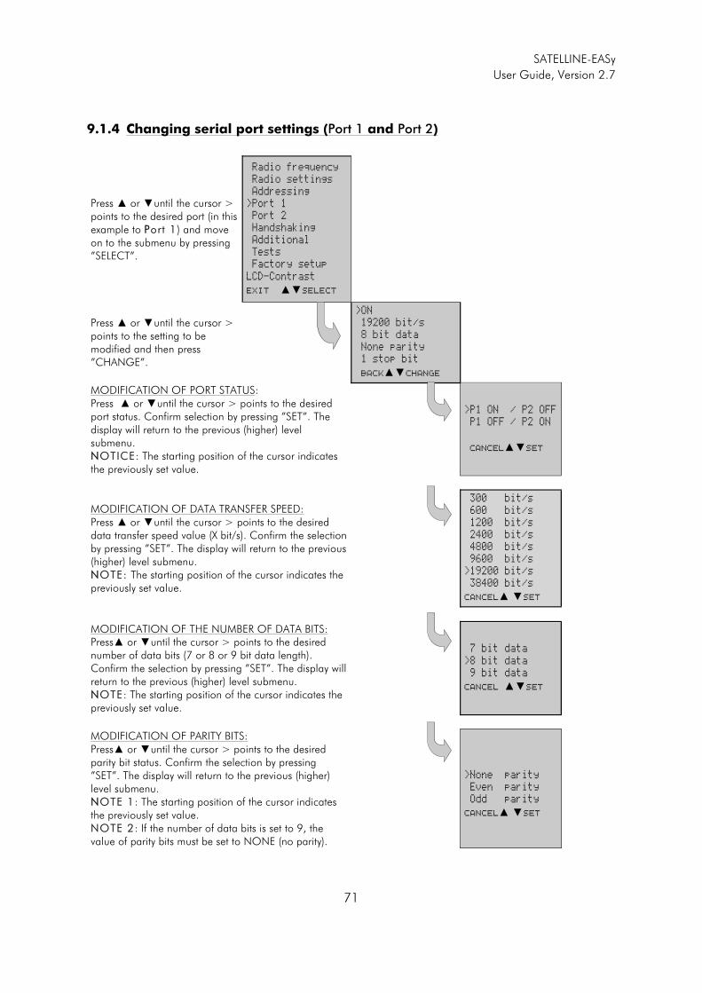
SATELLINE-EASy
User Guide, Version 2.7
71
9.1.4 Changing serial port settings (Port 1 and Port 2)
Press � or �until the cursor > points to the desired port (in this example to PPort 1) and move on to the submenu by pressing ”SELECT”.
Radio frequency
Radio settings
Addressing
>Port 1
Port 2
Handshaking
Additional
Tests
Factory setup
LCD-Contrast
Exit ��Select
Press � or �until the cursor > points to the setting to be modified and then press ”CHANGE”.
>ON
19200 bit/s
8 bit data
None parity
1 stop bit
Back��Change
MODIFICATION OF PORT STATUS: Press � or �until the cursor > points to the desired port status. Confirm selection by pressing ”SET”. The display will return to the previous (higher) level submenu. NNOTICE: The starting position of the cursor indicates the previously set value.
>P1 ON / P2 OFF
P1 OFF / P2 ON
Cancel��Set
MODIFICATION OF DATA TRANSFER SPEED: Press � or �until the cursor > points to the desired data transfer speed value (X bit/s). Confirm the selection by pressing ”SET”. The display will return to the previous (higher) level submenu. NNOTE: The starting position of the cursor indicates the previously set value.
300 bit/s
600 bit/s
1200 bit/s
2400 bit/s
4800 bit/s
9600 bit/s
>19200 bit/s
38400 bit/s
Cancel� �Set
MODIFICATION OF THE NUMBER OF DATA BITS: Press� or �until the cursor > points to the desired number of data bits (7 or 8 or 9 bit data length). Confirm the selection by pressing ”SET”. The display will return to the previous (higher) level submenu. NNOTE: The starting position of the cursor indicates the previously set value.
7 bit data
>8 bit data
9 bit data
Cancel ��Set
MODIFICATION OF PARITY BITS: Press� or �until the cursor > points to the desired parity bit status. Confirm the selection by pressing ”SET”. The display will return to the previous (higher) level submenu. NNOTE 1: The starting position of the cursor indicates the previously set value. NOTE 2: If the number of data bits is set to 9, the value of parity bits must be set to NONE (no parity).
>None parity
Even parity
Odd parity
Cancel� �Set
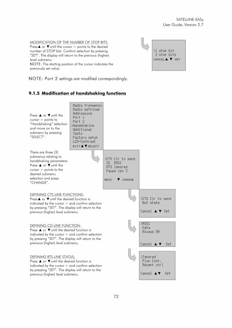
SATELLINE-EASy
User Guide, Version 2.7
72
MODIFICATION OF THE NUMBER OF STOP BITS: Press� or �until the cursor > points to the desired number of STOP bits. Confirm selection by pressing ”SET”. The display will return to the previous (higher) level submenu. NNOTE: The starting position of the cursor indicates the previously set value.
>1 stop bit
2 stop bits
Cancel� � Set
NNOTE: Port 2 settings are modified correspondingly.
9.1.5 Modification of handshaking functions
Press � or �until the cursor > points to “Handshaking” selection and move on to the submenu by pressing ”SELECT”.
Radio frequency
Radio settings
Addressing
Port 1
Port 2
>Handshaking
Additional
Tests
Factory setup
LCD-Contrast
Exit��Select
There are three (3) submenus relating to handshaking parameters. Press � or �until the cursor > points to the desired submenu selection and press ”CHANGE”.
>CTS Clr to send
CD RSSI
RTS Ignored
Pause len 3
Back � Change
DEFINING CTS-LINE FUNCTIONS: Press� or �until the desired function is indicated by the cursor > and confirm selection by pressing ”SET”. The display will return to the previous (higher) level submenu.
>CTS Clr to send
Buf state
Cancel � � Set
DEFINING CD-LINE FUNCTION: Press � or �until the desired function is indicated by the cursor > and confirm selection by pressing ”SET”. The display will return to the previous (higher) level submenu.
>RSSI
Data
Always ON
Cancel � � Set
DEFINING RTS-LINE STATUS: Press � or �until the desired function is indicated by the cursor > and confirm selection by pressing ”SET”. The display will return to the previous (higher) level submenu.
>Ignored
Flow Cont.
Recept ctrl
Cancel �� Set
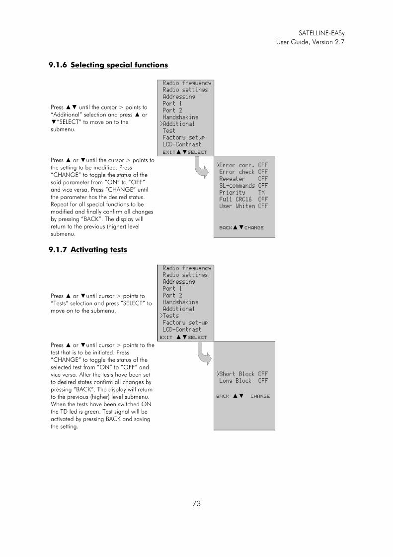
SATELLINE-EASy
User Guide, Version 2.7
73
9.1.6 Selecting special functions
Press �� until the cursor > points to “Additional” selection and press � or �”SELECT” to move on to the submenu.
Radio frequency
Radio settings
Addressing
Port 1
Port 2
Handshaking
>Additional
Test
Factory setup
LCD-Contrast
Exit��Select
Press � or �until the cursor > points to the setting to be modified. Press ”CHANGE” to toggle the status of the said parameter from ”ON” to ”OFF” and vice versa. Press ”CHANGE” until the parameter has the desired status. Repeat for all special functions to be modified and finally confirm all changes by pressing ”BACK”. The display will return to the previous (higher) level submenu.
>Error corr. OFF
Error check OFF
Repeater OFF
SL-commands OFF
Priority TX
Full CRC16 OFF
User Whiten OFF
Back��Change
9.1.7 Activating tests
Press � or �until cursor > points to “Tests” selection and press ”SELECT” to move on to the submenu.
Radio frequency
Radio settings
Addressing
Port 1
Port 2
Handshaking
Additional
>Tests
Factory set-up
LCD-Contrast
Exit ��Select
Press � or �until cursor > points to the test that is to be initiated. Press ”CHANGE” to toggle the status of the selected test from ”ON” to ”OFF” and vice versa. After the tests have been set to desired states confirm all changes by pressing ”BACK”. The display will return to the previous (higher) level submenu. When the tests have been switched ON the TD led is green. Test signal will be activated by pressing BACK and saving the setting.
>Short Block OFF
Long Block OFF
Back �� Change
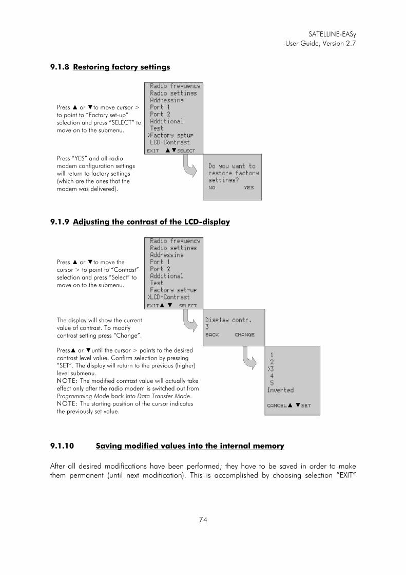
SATELLINE-EASy
User Guide, Version 2.7
74
9.1.8 Restoring factory settings
Press � or �to move cursor > to point to “Factory set-up” selection and press ”SELECT” to move on to the submenu.
Radio frequency
Radio settings
Addressing
Port 1
Port 2
Additional
Test
>Factory setup
LCD-Contrast
Exit ��Select
Press ”YES” and all radio modem configuration settings will return to factory settings (which are the ones that the modem was delivered).
Do you want to
restore factory
settings?
NO YES
9.1.9 Adjusting the contrast of the LCD-display
Press � or �to move the cursor > to point to “Contrast” selection and press ”Select” to move on to the submenu.
Radio frequency
Radio settings
Addressing
Port 1
Port 2
Additional
Test
Factory set-up
>LCD-Contrast
Exit� � Select
The display will show the current value of contrast. To modify contrast setting press ”Change”.
Display contr.
3
Back Change
Press� or �until the cursor > points to the desired contrast level value. Confirm selection by pressing ”SET”. The display will return to the previous (higher) level submenu. NNOTE: The modified contrast value will actually take effect only after the radio modem is switched out from Programming Mode back into Data Transfer Mode. NOTE: The starting position of the cursor indicates the previously set value.
1
2
>3
4
5
Inverted
Cancel� �Set
9.1.10 Saving modified values into the internal memory
After all desired modifications have been performed; they have to be saved in order to make them permanent (until next modification). This is accomplished by choosing selection ”EXIT”

SATELLINE-EASy
User Guide, Version 2.7
75
from the main menu. The display will then show a message (see below) asking a confirmation of the performed modifications. BBy choosing ”YYES” all modif ications are saved into the non-volati le memory inside the radio modem. By choosing ”NO” all modification performed are cancelled and previous settings remaining in the non-volatile memory.
Press ”YES” to save all modifications into the non-volatile memory and ”NO”, if modifications are to be cancelled.
Do you want to
make changes
permanent?
No � YES
9.2 Changing parameters using the SL-COMMANDS
The controlling terminal device can change the configuration settings of a radio modem. This is accomplished with the help of SL-commands, which can be used during data transfer. SL-commands can be used to change e.g. the frequency or addresses. It is also possible to interrogate a radio modem in order to gain information concerning current settings that are in use. The terminal device is either a PC or a programmable logic (PLC) together with suitable (terminal) program. SL-commands must be enabled using Programming Mode before they can be used. An SL-command is a one continuous string of characters, which is separated from other data by pauses that are equal or greater than time defined by Pause length parameter in the set-up. No extra characters are allowed at the end of an SL-command. Serial interface settings are the same as in data transfer and pin 12 of the serial connector MUST NOT be connected to ground (GND). SL-command is properly recognised also in the case when the command string is terminated in <CR> (=ASCII character no. 13, Carriage Return, 0x0d) or <CR><LF> (<LF> = ASCII char. no. 10, Line Feed, 0x0a). If multiple SL commands are sent to the radio modem the next command can be given after receiving the response ("Ok" or "Error") of the proceeding command. In addition, it is recommended to implement a timeout to the terminal software for recovering the case when no response is received from the radio modem. When the power of a radio modem is switched off the configuration settings of a radio modem always return to values defined initially using the Programming Mode, thus resetting any settings changed using SL-commands during power on. It is however possible to save settings changed by using SL-commands and to make them the new configuration settings. The radio modem will acknowledge all commands by returning an "OOK" (command carried out or accepted) or the requested value, or an "EERROR" (command not carried out or interpreted as erroneous) message. In case you need more information on the time delays related to the use of SL-commands, please contact the manufacturer. In order to get information of the latest and/or special SL-commands please contact SATEL Oy.
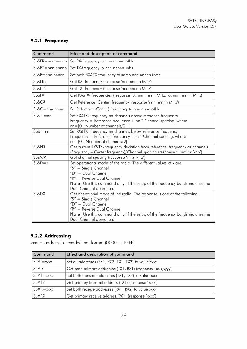
SATELLINE-EASy
User Guide, Version 2.7
76
9.2.1 Frequency
Command Effect and description of command
SL&FR=nnn.nnnnn Set RX-frequency to nnn.nnnnn MHz
SL&FT=nnn.nnnnn Set TX-frequency to nnn.nnnnn MHz
SL&F=nnn.nnnnn Set both RX&TX-frequency to same nnn.nnnnn MHz
SL&FR? Get RX- frequency (response 'nnn.nnnnn MHz')
SL&FT? Get TX- frequency (response 'nnn.nnnnn MHz')
SL&F? Get RX&TX- frequencies (response TX nnn.nnnnn MHz, RX nnn.nnnnn MHz)
SL&C? Get Reference (Center) frequency (response 'nnn.nnnnn MHz')
SL&C=nnn.nnnn Set Reference (Center) frequency to nnn.nnnn MHz
SL&+=nn Set RX&TX- frequency nn channels above reference frequency Frequency = Reference frequency + nn * Channel spacing, where nn=[0...Number of channels/2]
SL&-=nn Set RX&TX- frequency nn channels below reference frequency Frequency = Reference frequency – nn * Channel spacing, where nn=[0…Number of channels/2]
SL&N?
Get current RX&TX- frequency deviation from reference frequency as channels (Frequency – Center frequency)/Channel spacing (response ‘+nn’ or ‘-nn’)
SL&W? Get channel spacing (response ‘nn.n kHz’)
SL&D=x Set operational mode of the radio. The different values of x are: ”S” = Single Channel ”D” = Dual Channel ”R” = Reverse Dual Channel NNote! Use this command only, if the setup of the frequency bands matches the Dual Channel operation.
SL&D?
Get operational mode of the radio. The response is one of the following: ”S” = Single Channel ”D” = Dual Channel ”R” = Reverse Dual Channel NNote! Use this command only, if the setup of the frequency bands matches the Dual Channel operation.
9.2.2 Addressing
xxxx = address in hexadecimal format (0000 … FFFF)
Command Effect and description of command
SL#I=xxxx Set all addresses (RX1, RX2, TX1, TX2) to value xxxx
SL#I? Get both primary addresses (TX1, RX1) (response ’xxxx;yyyy’)
SL#T=xxxx Set both transmit addresses (TX1, TX2) to value xxxx
SL#T? Get primary transmit address (TX1) (response ‘xxxx’)
SL#R=xxxx Set both receive addresses (RX1, RX2) to value xxxx
SL#R? Get primary receive address (RX1) (response ‘xxxx’)
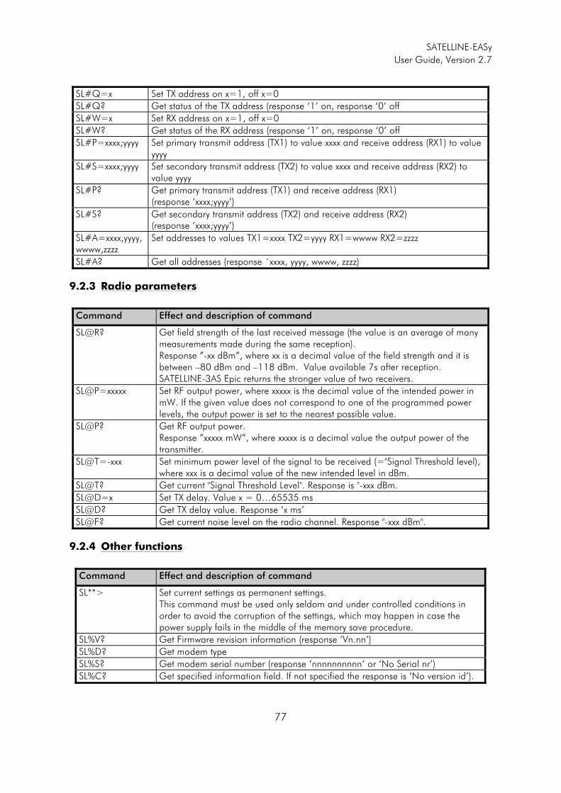
SATELLINE-EASy
User Guide, Version 2.7
77
SL#Q=x Set TX address on x=1, off x=0
SL#Q? Get status of the TX address (response ‘1’ on, response ‘0’ off
SL#W=x Set RX address on x=1, off x=0
SL#W? Get status of the RX address (response ‘1’ on, response ‘0’ off
SL#P=xxxx;yyyy Set primary transmit address (TX1) to value xxxx and receive address (RX1) to value yyyy
SL#S=xxxx;yyyy Set secondary transmit address (TX2) to value xxxx and receive address (RX2) to value yyyy
SL#P? Get primary transmit address (TX1) and receive address (RX1) (response ‘xxxx;yyyy’)
SL#S? Get secondary transmit address (TX2) and receive address (RX2) (response ‘xxxx;yyyy’)
SL#A=xxxx,yyyy,wwww,zzzz
Set addresses to values TX1=xxxx TX2=yyyy RX1=wwww RX2=zzzz
SL#A? Get all addresses (response ´xxxx, yyyy, wwww, zzzz)
9.2.3 Radio parameters
Command Effect and description of command
SL@R? Get field strength of the last received message (the value is an average of many measurements made during the same reception). Response ”-xx dBm”, where xx is a decimal value of the field strength and it is between –80 dBm and –118 dBm. Value available 7s after reception. SATELLINE-3AS Epic returns the stronger value of two receivers.
SL@P=xxxxx Set RF output power, where xxxxx is the decimal value of the intended power in mW. If the given value does not correspond to one of the programmed power levels, the output power is set to the nearest possible value.
SL@P? Get RF output power. Response ”xxxxx mW”, where xxxxx is a decimal value the output power of the transmitter.
SL@T=-xxx Set minimum power level of the signal to be received (="Signal Threshold level), where xxx is a decimal value of the new intended level in dBm.
SL@T? Get current "Signal Threshold Level". Response is "-xxx dBm.
SL@D=x Set TX delay. Value x = 0…65535 ms
SL@D? Get TX delay value. Response ‘x ms’
SL@F? Get current noise level on the radio channel. Response "-xxx dBm".
9.2.4 Other functions
Command Effect and description of command
SL**> Set current settings as permanent settings. This command must be used only seldom and under controlled conditions in order to avoid the corruption of the settings, which may happen in case the power supply fails in the middle of the memory save procedure.
SL%V? Get Firmware revision information (response ’Vn.nn’)
SL%D? Get modem type
SL%S? Get modem serial number (response ‘nnnnnnnnnn’ or ‘No Serial nr’)
SL%C? Get specified information field. If not specified the response is ‘No version id’).
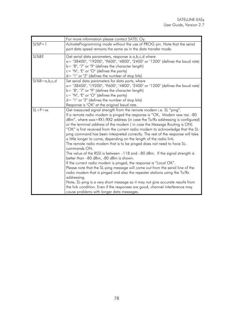
SATELLINE-EASy
User Guide, Version 2.7
78
For more information please contact SATEL Oy.
SL%P=1 ActivateProgramming mode without the use of PROG pin. Note that the serial port data speed remains the same as in the data transfer mode.
SL%B? Get serial data parameters, response is a,b,c,d where a= "38400", "19200", "9600", "4800", "2400" or "1200" (defines the baud rate) b= "8", "7" or "9" (defines the character length) c= "N", "E" or "O" (defines the parity) d= "1" or "2" (defines the number of stop bits)
SL%B=a,b,c,d Set serial data parameters for data ports, where a= "38400", "19200", "9600", "4800", "2400" or "1200" (defines the baud rate) b= "8", "7" or "9" (defines the character length) c= "N", "E" or "O" (defines the parity) d= "1" or "2" (defines the number of stop bits) Response is "OK" at the original baud rate.
SL+P=xx Get measured signal strength from the remote modem i.e. SL “ping”. If a remote radio modem is pinged the response is “OK, Modem xxxx rssi –80 dBm”, where xxxx=RX1/RX2 address (in case the Tx/Rx addressing is configured) or the terminal address of the modem ( in case the Message Routing is ON). “OK” is first received from the current radio modem to acknowledge that the SL-ping command has been interpreted correctly. The rest of the response will take a little longer to come, depending on the length of the radio link. The remote radio modem that is to be pinged does not need to have SL-commands ON. The value of the RSSI is between –118 and –80 dBm. If the signal strength is better than –80 dBm, -80 dBm is shown. If the current radio modem is pinged, the response is “Local OK”. Please note that the SL-ping message will come out from the serial line of the radio modem that is pinged and also the repeater stations using the Tx/Rx addressing. Note, SL-ping is a very short message so it may not give accurate results from the link condition. Even if the responses are good, channel interference may cause problems with longer data messages.
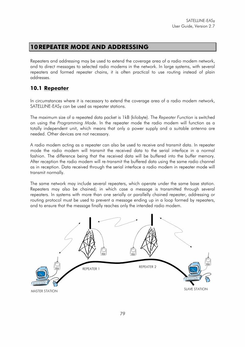
SATELLINE-EASy
User Guide, Version 2.7
79
10 REPEATER MODE AND ADDRESSING
Repeaters and addressing may be used to extend the coverage area of a radio modem network, and to direct messages to selected radio modems in the network. In large systems, with several repeaters and formed repeater chains, it is often practical to use routing instead of plain addresses.
10.1 Repeater
In circumstances where it is necessary to extend the coverage area of a radio modem network, SATELLINE-EASy can be used as repeater stations. The maximum size of a repeated data packet is 1kB (kilobyte). The Repeater Function is switched on using the Programming Mode. In the repeater mode the radio modem will function as a totally independent unit, which means that only a power supply and a suitable antenna are needed. Other devices are not necessary. A radio modem acting as a repeater can also be used to receive and transmit data. In repeater mode the radio modem will transmit the received data to the serial interface in a normal fashion. The difference being that the received data will be buffered into the buffer memory. After reception the radio modem will re-transmit the buffered data using the same radio channel as in reception. Data received through the serial interface a radio modem in repeater mode will transmit normally. The same network may include several repeaters, which operate under the same base station. Repeaters may also be chained; in which case a message is transmitted through several repeaters. In systems with more than one serially or parallelly chained repeater, addressing or routing protocol must be used to prevent a message ending up in a loop formed by repeaters, and to ensure that the message finally reaches only the intended radio modem.
MASTER STATION
REPEATER 1REPEATER 2
SLAVE STATION
SATELLINE-EASy
User Guide, Version 2.7
80
10.2 Addressing
Addresses can be used to route a data message to the desired destination or to separate two parallel networks from each other. In networks with repeaters it is usually necessary to use addresses to prevent data messages from ending up in loops formed by repeaters. In case of setting the “Message Routing” function in use, Tx / Rx addresses are ignored by the modem. SATELLINE-EASy allows the use of individual addresses both for reception and transmission. Addresses can be switched on separately, or simultaneously, in both data transfer directions. The radio modem contains two transmission and two reception addresses, which are knows as the primary address and secondary address. The primary address is used whenever data from the serial interface is transmitted. At the receiving end, the radio modem will receive using either of the two receive addresses. Secondary transmit address is only used in repeater applications. Radio modems configured to function as repeaters, will repeat data messages using either the primary or secondary address, depending upon which address was used during the reception of the data message. If only one address pair is needed in a network, both addresses must be set the same (TX1 = TX2 and RX1 = RX2). It is also possible to transfer the received address onto the serial interface. The address is composed of two characters totalling 16 bits, resulting in over 65,000 different address combinations The address is attached to the beginning of each data packet sent by the radio modem. When a radio modem receives a data packet whilst using addressing mode, the radio modem will check the first two characters of each received data packet to ensure that the packet in question was intended for the correct radio modem.
ADD H ADD L DATA Address may be selected between 0000h…FFFFh (h = hexadecimal, corresponding decimal numbers are 0-65535). EExample: address 1234h (4660 in decimal format), where 12h is ADD H and 34h is ADD L.
Example: address ABFFh (44031 in decimal format), where ABh is ADD H and FFh is ADD L.
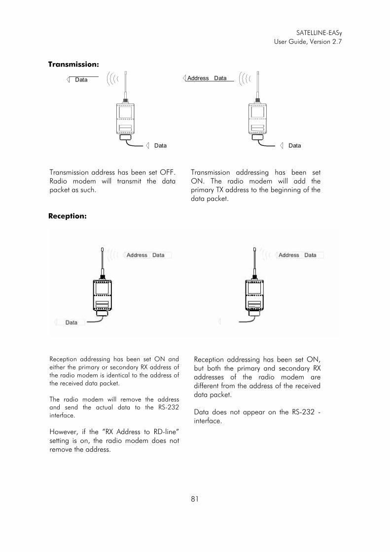
SATELLINE-EASy
User Guide, Version 2.7
81
Transmission:
Data Address Data
DataData Transmission address has been set OFF. Radio modem will transmit the data packet as such.
Transmission addressing has been set ON. The radio modem will add the primary TX address to the beginning of the data packet.
Reception:
Reception addressing has been set ON and either the primary or secondary RX address of the radio modem is identical to the address of the received data packet. The radio modem will remove the address and send the actual data to the RS-232 interface.
However, if the ”RX Address to RD-line” setting is on, the radio modem does not remove the address.
Reception addressing has been set ON, but both the primary and secondary RX addresses of the radio modem are different from the address of the received data packet. Data does not appear on the RS-232 -interface.

SATELLINE-EASy
User Guide, Version 2.7
82
Reception addressing has been set OFF.
The radio modem will transfer all received data to the RS-232 -interface.
Reception addressing has been set OFF.
The radio modem will consider the characters of the address as a part of the data and will send all the characters to the RS-232 interface.
Reception addressing has been set ON but there is no address in the data packet.
Data will appear on the RS-232 interface ONLY if the first 2 characters of the data match either of its own RX address. The radio modem will remove those 2 characters of data.
10.2.1 Connection between two points
When forming a connection between two points it is recommended that both the reception and transmission addresses are identical in both radio modems. This is the easiest way to control addresses and the risk caused by interference from other systems operating in the same area is minimal. Example: by setting all addresses of both radio modems to a value ´1234´, they will accept only those messages which contain this address, and they will use this same value when transmitting data. If the channel is reserved for use only by the said network, or if the terminal devices are responsible for addressing, it is not necessary to use addressing in the radio modems.
10.2.2 System of one base station and several substations
In systems with several substations, the base station must know to which substation each message is intended, and from which substation each received message originates. Usually terminal devices handle addressing completely, but it is also possible to use the addressing functionality of the radio modems.
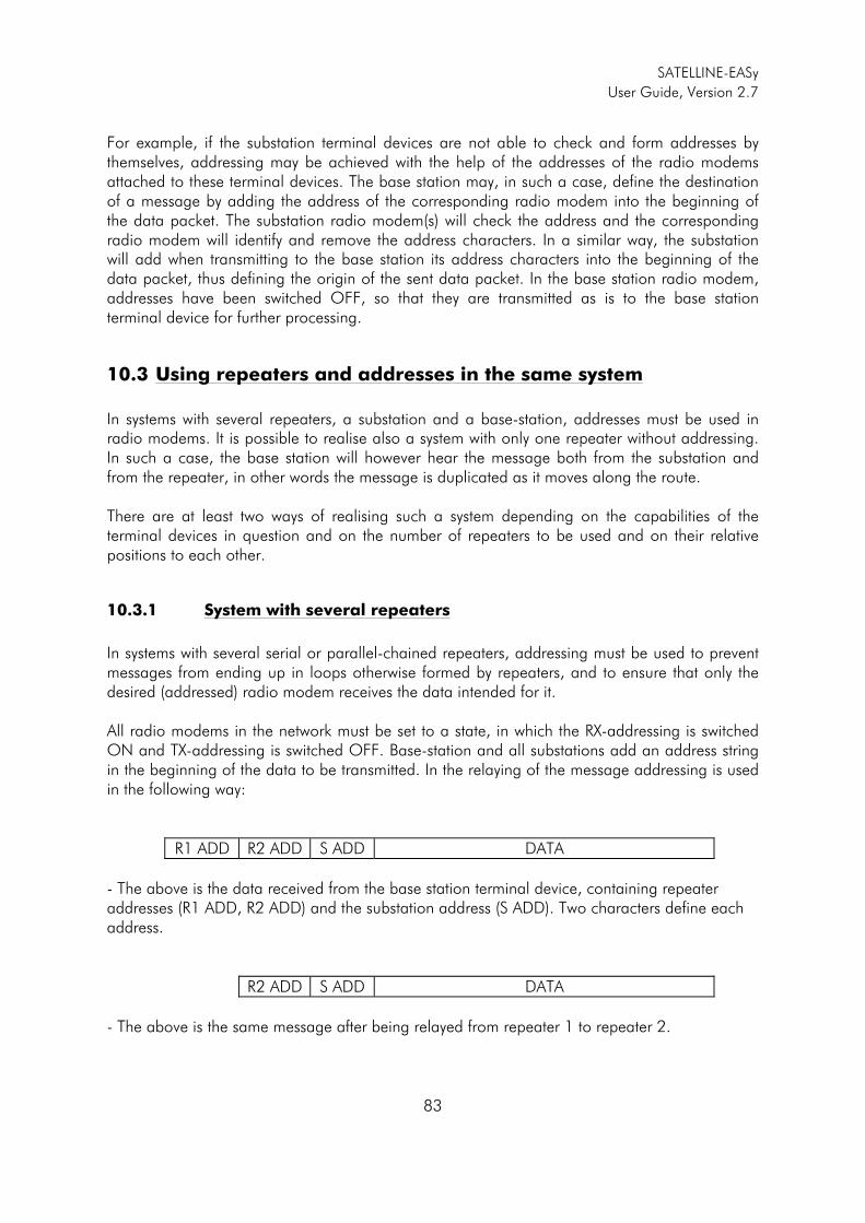
SATELLINE-EASy
User Guide, Version 2.7
83
For example, if the substation terminal devices are not able to check and form addresses by themselves, addressing may be achieved with the help of the addresses of the radio modems attached to these terminal devices. The base station may, in such a case, define the destination of a message by adding the address of the corresponding radio modem into the beginning of the data packet. The substation radio modem(s) will check the address and the corresponding radio modem will identify and remove the address characters. In a similar way, the substation will add when transmitting to the base station its address characters into the beginning of the data packet, thus defining the origin of the sent data packet. In the base station radio modem, addresses have been switched OFF, so that they are transmitted as is to the base station terminal device for further processing.
10.3 Using repeaters and addresses in the same system
In systems with several repeaters, a substation and a base-station, addresses must be used in radio modems. It is possible to realise also a system with only one repeater without addressing. In such a case, the base station will however hear the message both from the substation and from the repeater, in other words the message is duplicated as it moves along the route. There are at least two ways of realising such a system depending on the capabilities of the terminal devices in question and on the number of repeaters to be used and on their relative positions to each other.
10.3.1 System with several repeaters
In systems with several serial or parallel-chained repeaters, addressing must be used to prevent messages from ending up in loops otherwise formed by repeaters, and to ensure that only the desired (addressed) radio modem receives the data intended for it. All radio modems in the network must be set to a state, in which the RX-addressing is switched ON and TX-addressing is switched OFF. Base-station and all substations add an address string in the beginning of the data to be transmitted. In the relaying of the message addressing is used in the following way:
R1 ADD R2 ADD S ADD DATA
- The above is the data received from the base station terminal device, containing repeater addresses (R1 ADD, R2 ADD) and the substation address (S ADD). Two characters define each address.
R2 ADD S ADD DATA
- The above is the same message after being relayed from repeater 1 to repeater 2.
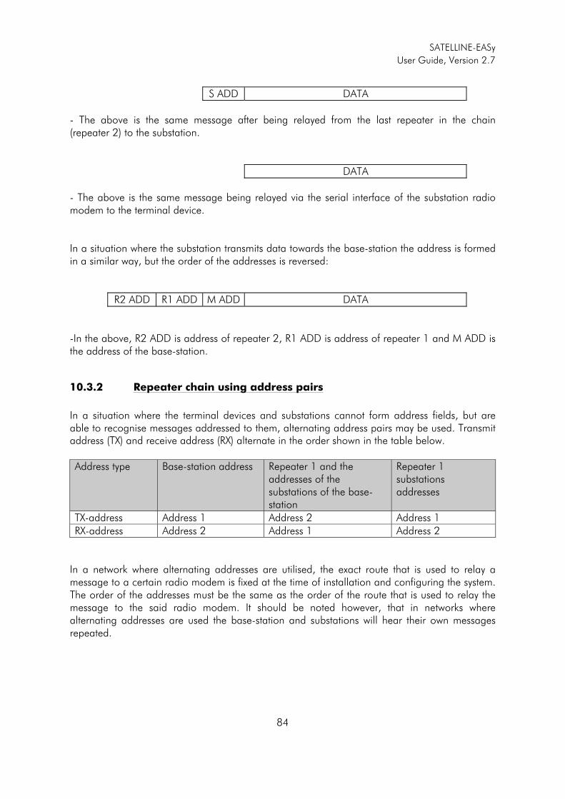
SATELLINE-EASy
User Guide, Version 2.7
84
S ADD DATA
- The above is the same message after being relayed from the last repeater in the chain (repeater 2) to the substation.
DATA
- The above is the same message being relayed via the serial interface of the substation radio modem to the terminal device. In a situation where the substation transmits data towards the base-station the address is formed in a similar way, but the order of the addresses is reversed:
R2 ADD R1 ADD M ADD DATA
-In the above, R2 ADD is address of repeater 2, R1 ADD is address of repeater 1 and M ADD is the address of the base-station.
10.3.2 Repeater chain using address pairs
In a situation where the terminal devices and substations cannot form address fields, but are able to recognise messages addressed to them, alternating address pairs may be used. Transmit address (TX) and receive address (RX) alternate in the order shown in the table below. Address type Base-station address Repeater 1 and the
addresses of the substations of the base-station
Repeater 1 substations addresses
TX-address Address 1 Address 2 Address 1 RX-address Address 2 Address 1 Address 2
In a network where alternating addresses are utilised, the exact route that is used to relay a message to a certain radio modem is fixed at the time of installation and configuring the system. The order of the addresses must be the same as the order of the route that is used to relay the message to the said radio modem. It should be noted however, that in networks where alternating addresses are used the base-station and substations will hear their own messages repeated.
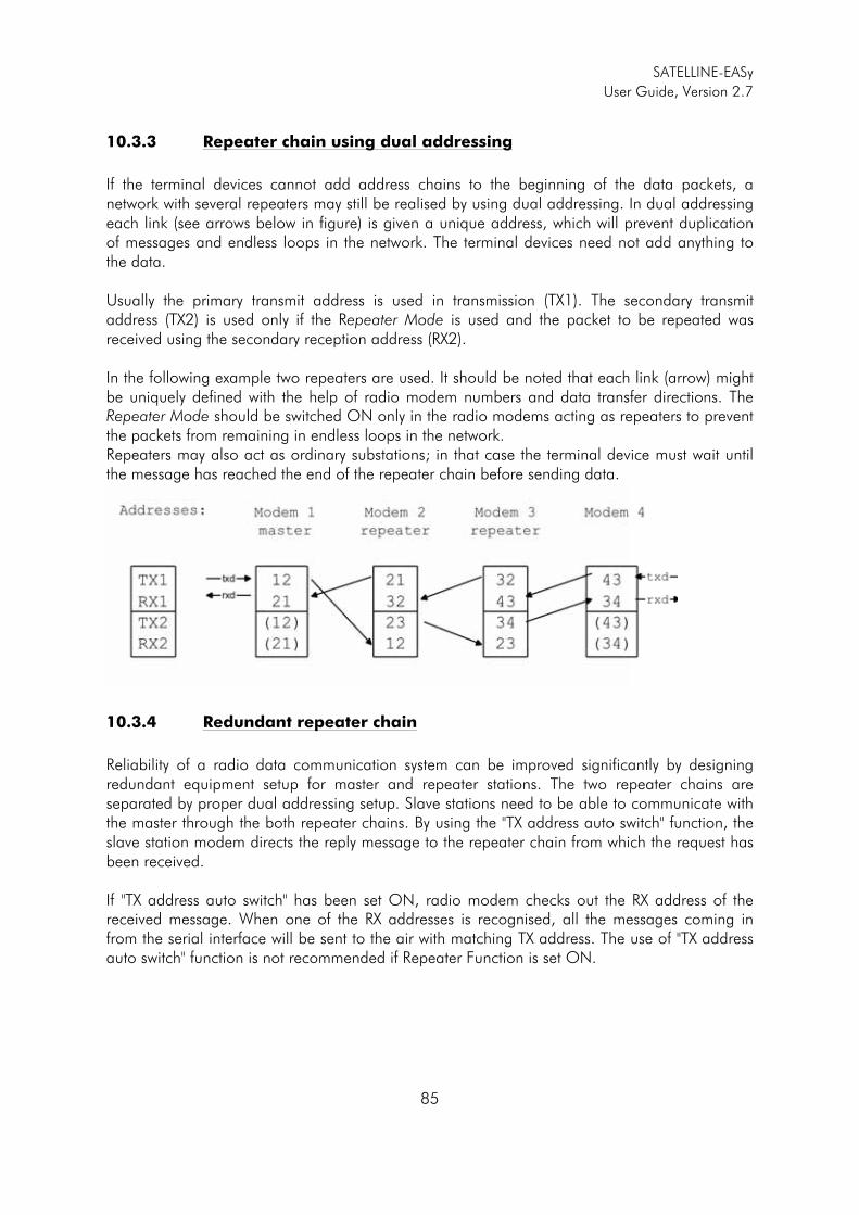
SATELLINE-EASy
User Guide, Version 2.7
85
10.3.3 Repeater chain using dual addressing
If the terminal devices cannot add address chains to the beginning of the data packets, a network with several repeaters may still be realised by using dual addressing. In dual addressing each link (see arrows below in figure) is given a unique address, which will prevent duplication of messages and endless loops in the network. The terminal devices need not add anything to the data. Usually the primary transmit address is used in transmission (TX1). The secondary transmit address (TX2) is used only if the Repeater Mode is used and the packet to be repeated was received using the secondary reception address (RX2).
In the following example two repeaters are used. It should be noted that each link (arrow) might be uniquely defined with the help of radio modem numbers and data transfer directions. The Repeater Mode should be switched ON only in the radio modems acting as repeaters to prevent the packets from remaining in endless loops in the network. Repeaters may also act as ordinary substations; in that case the terminal device must wait until the message has reached the end of the repeater chain before sending data.
10.3.4 Redundant repeater chain
Reliability of a radio data communication system can be improved significantly by designing redundant equipment setup for master and repeater stations. The two repeater chains are separated by proper dual addressing setup. Slave stations need to be able to communicate with the master through the both repeater chains. By using the "TX address auto switch" function, the slave station modem directs the reply message to the repeater chain from which the request has been received. If "TX address auto switch" has been set ON, radio modem checks out the RX address of the received message. When one of the RX addresses is recognised, all the messages coming in from the serial interface will be sent to the air with matching TX address. The use of "TX address auto switch" function is not recommended if Repeater Function is set ON.
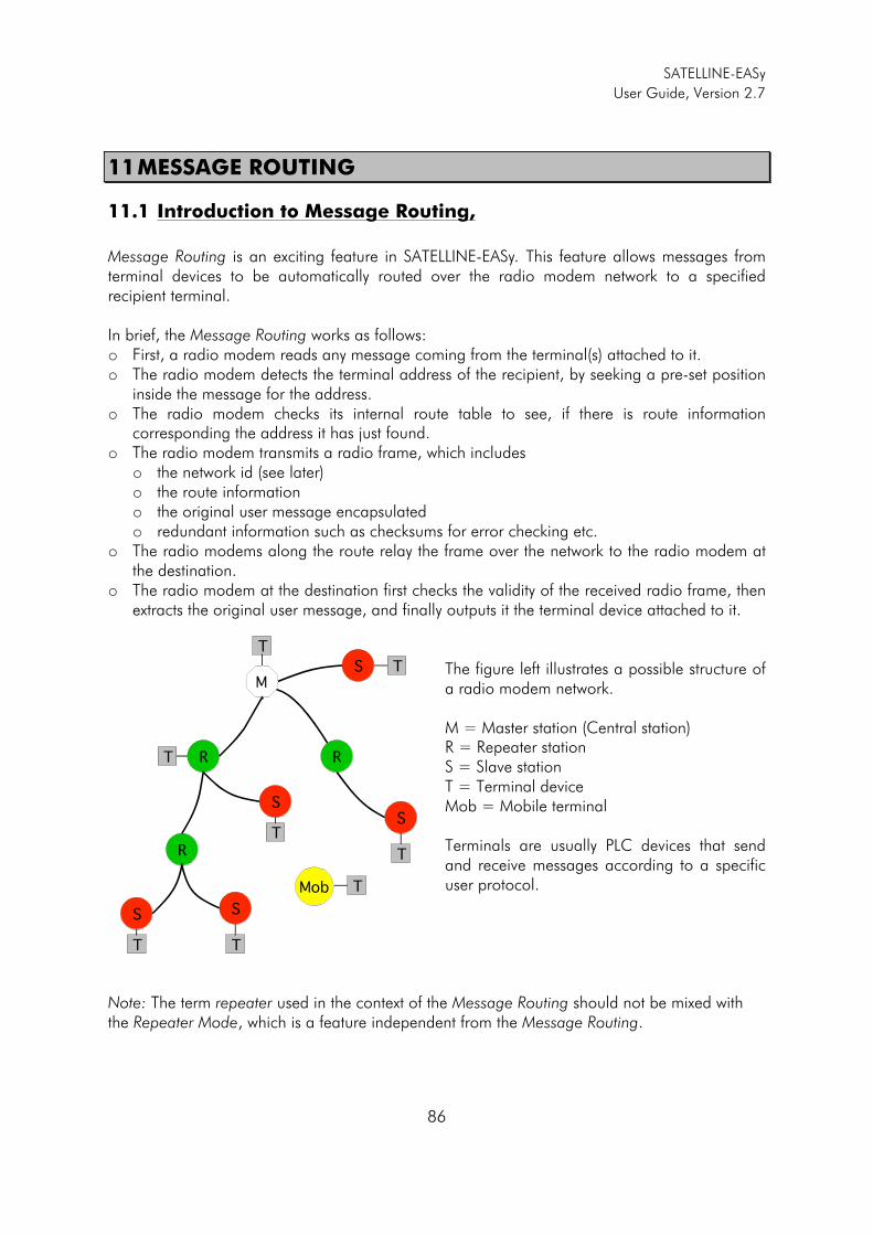
SATELLINE-EASy
User Guide, Version 2.7
86
11 MESSAGE ROUTING
11.1 Introduction to Message Routing,
Message Routing is an exciting feature in SATELLINE-EASy. This feature allows messages from terminal devices to be automatically routed over the radio modem network to a specified recipient terminal. In brief, the Message Routing works as follows: o First, a radio modem reads any message coming from the terminal(s) attached to it. o The radio modem detects the terminal address of the recipient, by seeking a pre-set position
inside the message for the address. o The radio modem checks its internal route table to see, if there is route information
corresponding the address it has just found. o The radio modem transmits a radio frame, which includes
o the network id (see later) o the route information o the original user message encapsulated o redundant information such as checksums for error checking etc.
o The radio modems along the route relay the frame over the network to the radio modem at the destination.
o The radio modem at the destination first checks the validity of the received radio frame, then extracts the original user message, and finally outputs it the terminal device attached to it.
The figure left illustrates a possible structure of a radio modem network. M = Master station (Central station) R = Repeater station S = Slave station T = Terminal device Mob = Mobile terminal Terminals are usually PLC devices that send and receive messages according to a specific user protocol.
Note: The term repeater used in the context of the Message Routing should not be mixed with the Repeater Mode, which is a feature independent from the Message Routing.
M
R R
R
S
SS
S
S
T
T
T
TT
T
T
Mob T
SATELLINE-EASy
User Guide, Version 2.7
87
11.1.1 Features of Message Routing
The Message Routing feature of the SATELLINE-EASy is designed to be a fast and transparent to fit real time systems. The features include:
o Transparent to user protocols. o Easy construction of a network containing several repeaters. o Any radio modem may operate as a repeater, i.e. dedicated repeaters are not usually
needed thus cutting down on costs. o Large areas of coverage may be implemented by using only one radio channel. o The use of mobile substations is also possible to some extent. o The system will be fully deterministic i.e. the transmission delays are predictable. Because
of that, the principle of Message Routing is connectionless. o Added redundancy, as a failing radio modem can be, in certain cases, bypassed with
another radio modem positioned in the same coverage area. o Message Routing is intended mainly for the protocols based on polling scheme and a
single master station.
11.1.2 Limitations of Message Routing
o It is assumed that the position of the address field in the user messages is fixed. However
some special protocols are supported: o IEC 60870-5-101 is a protocol commonly used in control applications of power
lines. o RP570 protocol
o The message cannot end to the address; there must be at least one character after the address.
o It is assumed that there is only one message at a time inside the network simultaneous messages could cause collisions.
o The max number of the routes depends on the actual hardware and the Firmware version.
o Operation of the Tx / Rx addresses is automatically blocked in the case of switching the “Message Routing” function on.
11.1.3 Getting started with Message Routing
The design of any radio modem system requires very precise planning. Once the choices between devices, their location, installation, maintenance etc. are clear, the Message Routing for the system can be implemented. Planning your Message Routing System 1. Decide which mode of the Message Routing suits the system - Source Mode or Virtual Mode. See the following paragraphs for details. 2. Design a layout of the system describing the settings such as protocol, addresses of the terminal equipment, radio frequencies and so on.
SATELLINE-EASy
User Guide, Version 2.7
88
3. Configure the radio modems accordingly. There are two ways to configure the parameters related to the Message Routing: 1. SaTerm PC-program 2. Manual configuration in the setup menu. In either case, please check the chapter on Settings before changing the setup of the radio modems. Finally, when all the radio modems have correct settings, they are ready for further installation.
11.1.4 SaTerm and the configuration of the Message Routing
SaTerm is a PC based program that allows the user to design their required network simply and quickly using a graphical interface to literally draw the network plan on the screen.
o Firstly, a picture of the network is created to show all the radio modems and the intended route that the data is to take.
o Secondly, the required settings are defined in the drawing. o Finally, the setup of each actual radio modem can be uploaded by connecting the actual
radio modems one by one to the COM port, switching them to the programming mode, and clicking the transmit button of SaTerm.
Please check the user manual of SaTerm for more details. The figure below shows a typical snapshot taken from a SaTerm screen.
SATELLINE-EASy
User Guide, Version 2.7
89
11.1.5 Manual configuration of the Message Routing
The radio modems can be configured manually via the programming menu. However, this is recommended only if the structure of the network is very simple, or if it is desirable to define such special functions that are not possible to draw using the graphical interface of SaTerm. Examples of such cases are for example non tree-structured networks, or the use of same repeaters in several overlapping networks. The operation of the Message Routing must be clearly understood before configuring the radio modems manually.
11.1.6 Configuration of the protocol in Message Routing
A radio modem will detect the presence of an address used by inspecting the protocol from the message received via the serial interface. On the basis of this user address, all necessary information needed to relay the message to destination is fetched from an internal routing table inside a radio modem. The user protocol is not interpreted; instead, the user address is searched according to its location in the message. The beginning of the packet is located by a preceding pause in the byte stream. Message Routing can therefore be applied to most protocols with fixed address field position. The position and length of the address is defined by two settings: Offset and Length.
o Offset defines the number of bytes (0…15) preceding the address. o Length is the length of the address in the user protocol expressed in bytes (1…4).
A transmitting radio modem adds a routing header and a tail to the user message. Consequently, a radio modem that receives the message removes the header and tail - so the Message Routing scheme is transparent to the user protocol.
Offset Le ng th
B yte l eng th
USER ADDRESS
St art of data p ack et, Offse t=2 , L eng th=3
USER DATA
SATELLINE-EASy
User Guide, Version 2.7
90
11.2 Operating modes of Message Routing
The Message Routing has two different operating modes:
o Source Mode Routing o Virtual Mode Routing
The most important differences between the two modes are shown in the table below.
Property Source Mode Routing Virtual Mode Routing
Summary Slower, more functions Faster, less functions
Radio interference tolerance Yes, overhop function No
Support for mobile stations Yes No
Addition of substations to a network
Only master station needs to be reconfigured
Master station and consecutive repeaters need to be reconfigured
Changing routes Only master station needs to be reconfigured
All radio modems need to be reconfigured
Maximum length of route 13 hops No limit
Overhop function Yes No
Network ID Yes Yes
Storing of routing information Centralised Dispersed
Message Routing overhead (bytes)
10+2*number of hops 9
Maximum length of user protocol message (bytes)
1kB – Message Routing overhead 1kB – Message Routing overhead
Other issues common to the both modes:
o The maximum number of terminals depends on the radio network structure and the number of routes.
o Multiple terminal addresses may be attached to a radio modem. o The maximum length of a terminal address (in the user's protocol) is four bytes (FFFFFFFF
in hexadecimal). o The maximum length of the address of a radio modem is two bytes (FFFF in
hexadecimal).
01
3
2
X
Y
Z
System Modem
Y 1, 2
Z 1, 3
SATELLINE-EASy
User Guide, Version 2.7
91
11.3 Detailed description of Message Routing
11.3.1 Source Mode Routing
The above figure represents a network containing four (4) radio modems. Each radio modem is given a unique address (0…3). A terminal device has been attached to the three of the four radio modems and they communicate with each other using terminal addresses X, Y and Z, respectively. Radio modem 0 and terminal device X together constitute the base station of the network and all routing information of the network has been programmed into this base station. When the terminal device X transmits a packet to (e.g.) terminal Y, radio modem 0 will detect the address Y from the data received through the serial port. From the routing table a route 1,2 can be found to which the radio modem also adds its own address to define the route for return data. Radio modem 1 repeats the packet and radio modem 2 removes the address information from the received data packet thereby transferring only the original data to the serial interface. The address information received together with the packet is reversed (2, 1, 0) and saved to be used in the transmission of subsequent reply packets.
11.3.2 Virtual Mode Routing
Please contact SATEL for more information of Virtual Mode Routing.
11.3.3 Overhop function in Source Mode Routing
Master TD
Radio
Substat ion RD
M R1 R2 S
TD RD
t
Master R1 R2
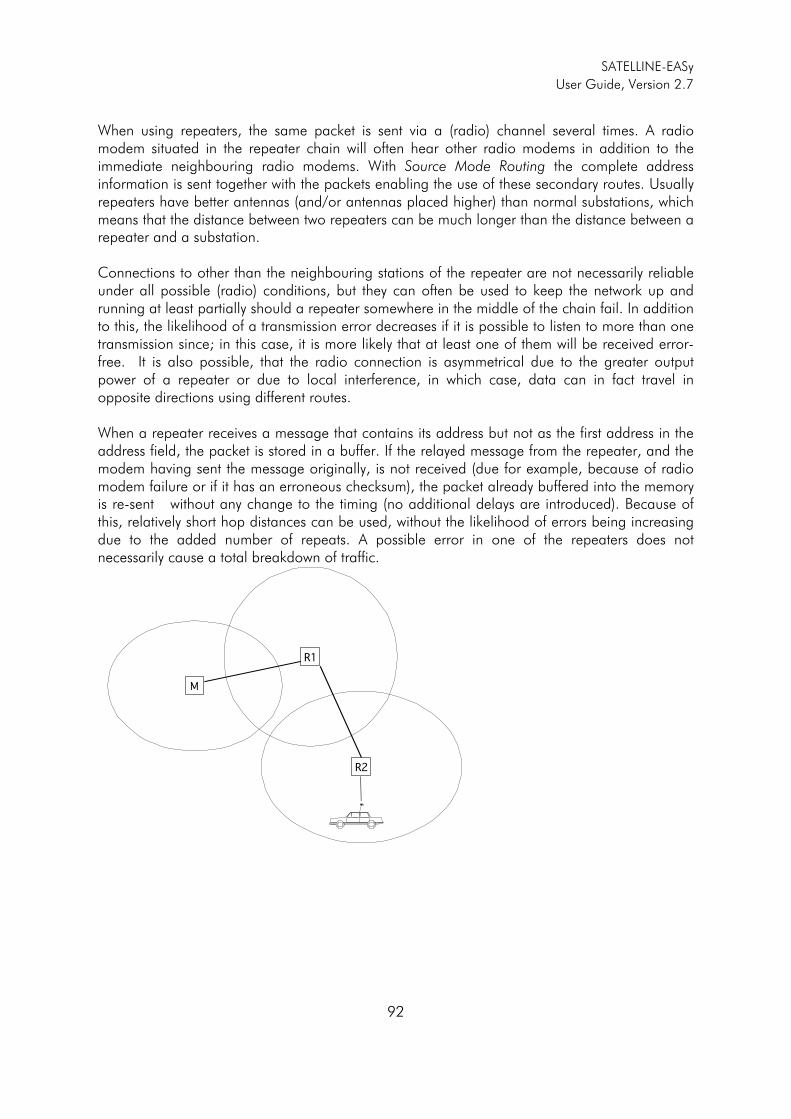
SATELLINE-EASy
User Guide, Version 2.7
92
When using repeaters, the same packet is sent via a (radio) channel several times. A radio modem situated in the repeater chain will often hear other radio modems in addition to the immediate neighbouring radio modems. With Source Mode Routing the complete address information is sent together with the packets enabling the use of these secondary routes. Usually repeaters have better antennas (and/or antennas placed higher) than normal substations, which means that the distance between two repeaters can be much longer than the distance between a repeater and a substation. Connections to other than the neighbouring stations of the repeater are not necessarily reliable under all possible (radio) conditions, but they can often be used to keep the network up and running at least partially should a repeater somewhere in the middle of the chain fail. In addition to this, the likelihood of a transmission error decreases if it is possible to listen to more than one transmission since; in this case, it is more likely that at least one of them will be received error-free. It is also possible, that the radio connection is asymmetrical due to the greater output power of a repeater or due to local interference, in which case, data can in fact travel in opposite directions using different routes. When a repeater receives a message that contains its address but not as the first address in the address field, the packet is stored in a buffer. If the relayed message from the repeater, and the modem having sent the message originally, is not received (due for example, because of radio modem failure or if it has an erroneous checksum), the packet already buffered into the memory is re-sent without any change to the timing (no additional delays are introduced). Because of this, relatively short hop distances can be used, without the likelihood of errors being increasing due to the added number of repeats. A possible error in one of the repeaters does not necessarily cause a total breakdown of traffic.
M
R2
R1
SATELLINE-EASy
User Guide, Version 2.7
93
The overhop function allows for the use of mobile substations. In the example above, a mobile substation is first located in the coverage area of repeater R2. The route is defined as M, R1, R2 and vehicle. When the vehicle moves to the coverage area of repeater R1, the radio modem picks the packet already from the transmission of R1. This is then transferred to the serial port using an additional delay, so that the timing does not differ from the first situation where the radio modem of the vehicle was in the coverage area of repeater R2. In this way a collision of the reply transmission and the transmission by repeater R2 is prevented. When the mobile station is transmitting, it is enough that at least one radio modem defined to be a part of the route receives the transmission.
11.3.4 Network ID
The Network ID is a string of up to eight characters, which is used to prevent the reception of the messages coming from an external system. The radio modems operating in the same system using Message Routing must have the same Network ID. Only the messages that have a matching Network ID are received.
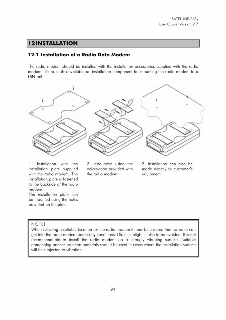
SATELLINE-EASy
User Guide, Version 2.7
94
12 INSTALLATION
12.1 Installation of a Radio Data Modem
The radio modem should be installed with the installation accessories supplied with the radio modem. There is also available an installation component for mounting the radio modem to a DIN-rail.
1. Installation with the installation plate supplied with the radio modem. The installation plate is fastened to the backside of the radio modem. The installation plate can be mounted using the holes provided on the plate.
2. Installation using the Velcro-tape provided with the radio modem.
3. Installation can also be made directly to customer’s equipment.
NOTE! When selecting a suitable location for the radio modem it must be ensured that no water can get into the radio modem under any conditions. Direct sunlight is also to be avoided. It is not recommendable to install the radio modem on a strongly vibrating surface. Suitable dampening and/or isolation materials should be used in cases where the installation surface will be subjected to vibration.
SATELLINE-EASy
User Guide, Version 2.7
95
12.1.1 Prepare installation of SATELLINE-EASy into the SATEL-321 casing
Before installing a SATELLINE-EASy casing, the battery pack function must be selected as follows: NOTE! Both serial ports must be RS-232 (Not LV-/TTL or RS-422). To get RS-232 on Port 2, the PWR-module of the modem must be separately specified in the ordered.
o Switch the radio modem into the Programming Mode o Select main menu selection “5” (Serial Port 2). o Enter selection “1” (Port Status). o Select “3” (BATT / LCD). o Select “4” (BATT / NO LCD). o Save the setting. o Switch the radio modem back into Data Transfer Mode.
For further information, please check the installation advice from the SATEL-321 user guide: Installing a radio modem into the SATEL-321 casing.
12.2 Antenna installation
12.2.1 Hand-held equipment
o �-wave antenna (wavelength at frequency of 450 MHz is approximately 70 cm) o Helix-antenna
Antennas are installed directly to the TNC-type antenna connector at the upper part of the radio modem.
12.2.2 Mobile equipment
o �-wave antenna o �-wave antenna
The ideal installation position is vertical, and there should be at least 0.5 m of free space around the antenna. In small systems a �-wave antenna is sufficient. A separate ground plane should be placed under the antenna (vehicle rooftop or the engine hood or trunk door are usually suitable). In problematic cases the most suitable type is a �-wave antenna. It can be installed directly at the top of a pipe with the added benefit of gaining as much as free space around the antenna as possible. In cases, which the antenna cannot be directly connected to the TNC-connector of the radio modem, a coaxial cable with 50 ohm impedance must be used between the antenna and the TNC-connector.

SATELLINE-EASy
User Guide, Version 2.7
96
12.2.3 Base stations
o Omni-directional antennas ( �- , �- or 5/8-wave antenna) o Directional antennas (yagi /multi-element antenna or corner antenna)
The antenna should be installed in a vertical position. The exact location of the antenna depends on several factors, such as the size of the overall system and the coverage area terrain contours. A rule of thumb is that the base station antenna should be located at the highest point of the coverage area and as close to the centre of the coverage area as possible. The base station antenna can also be located inside a building, if the walls of the building do not contain metal.
12.2.4 General antenna installation instructions
The reliability and the achievable coverage of useful signal strength can be severely affected by the positioning of the antenna. Antenna and cable connectors should have gold-plated pins and sockets, as use of low quality connectors can lead to eventual oxidation of the connector surfaces, which in turn may degrade the contact and cause additional attenuation. Good quality tools and materials must be used when installing radio modems, antennas and cables. The weather tolerance of the materials used must also be taken into account. Installed materials must withstand all foreseeable weather conditions (frost, excess sun, direct UV-radiation, seawater etc.). Also possible environmental pollution must be considered (acids, ozone etc.). Antennas must be installed well away from metallic objects. In the case of small antennas this distance should be at least � m. With large antennas the distance should be >5 m and in case of repeater antenna combinations >10 m. If the system contains a large number of radio modems, the best location for an antenna is the highest point of a building and possibly an additional antenna mast. If a separate antenna mast is used, the antenna can, if necessary, be installed sideways about 2…3 m from the mast itself. When installing an antenna possible interference sources must be considered. Such interference sources are, for example:
o mobile telephone network base station antennas o public telephone network base station antennas o television broadcast antennas o radio relay antennas o other radio modem systems o PC-related devices (approximately 5 m radius from antenna)
When ordering antennas we request you to note that antennas are always tuned to a specific frequency range. Simple antennas and antennas, which have been constructed of stacked yagi-antennas, are typically rather broadband. As the number of yagi-elements increases the frequency range becomes narrower.
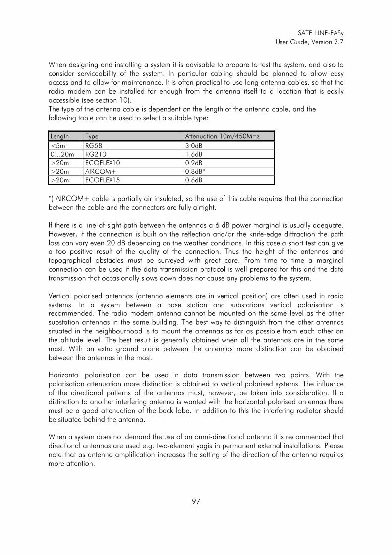
SATELLINE-EASy
User Guide, Version 2.7
97
When designing and installing a system it is advisable to prepare to test the system, and also to consider serviceability of the system. In particular cabling should be planned to allow easy access and to allow for maintenance. It is often practical to use long antenna cables, so that the radio modem can be installed far enough from the antenna itself to a location that is easily accessible (see section 10). The type of the antenna cable is dependent on the length of the antenna cable, and the following table can be used to select a suitable type:
Length Type Attenuation 10m/450MHz
<5m RG58 3.0dB
0…20m RG213 1.6dB
>20m ECOFLEX10 0.9dB
>20m AIRCOM+ 0.8dB*
>20m ECOFLEX15 0.6dB
*) AIRCOM+ cable is partially air insulated, so the use of this cable requires that the connection between the cable and the connectors are fully airtight. If there is a line-of-sight path between the antennas a 6 dB power marginal is usually adequate. However, if the connection is built on the reflection and/or the knife-edge diffraction the path loss can vary even 20 dB depending on the weather conditions. In this case a short test can give a too positive result of the quality of the connection. Thus the height of the antennas and topographical obstacles must be surveyed with great care. From time to time a marginal connection can be used if the data transmission protocol is well prepared for this and the data transmission that occasionally slows down does not cause any problems to the system. Vertical polarised antennas (antenna elements are in vertical position) are often used in radio systems. In a system between a base station and substations vertical polarisation is recommended. The radio modem antenna cannot be mounted on the same level as the other substation antennas in the same building. The best way to distinguish from the other antennas situated in the neighbourhood is to mount the antennas as far as possible from each other on the altitude level. The best result is generally obtained when all the antennas are in the same mast. With an extra ground plane between the antennas more distinction can be obtained between the antennas in the mast. Horizontal polarisation can be used in data transmission between two points. With the polarisation attenuation more distinction is obtained to vertical polarised systems. The influence of the directional patterns of the antennas must, however, be taken into consideration. If a distinction to another interfering antenna is wanted with the horizontal polarised antennas there must be a good attenuation of the back lobe. In addition to this the interfering radiator should be situated behind the antenna. When a system does not demand the use of an omni-directional antenna it is recommended that directional antennas are used e.g. two-element yagis in permanent external installations. Please note that as antenna amplification increases the setting of the direction of the antenna requires more attention.
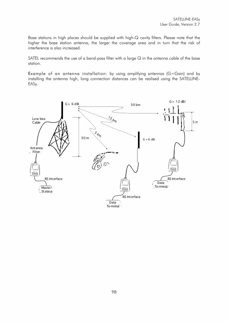
SATELLINE-EASy
User Guide, Version 2.7
98
Base stations in high places should be supplied with high-Q cavity filters. Please note that the higher the base station antenna, the larger the coverage area and in turn that the risk of interference is also increased. SATEL recommends the use of a band-pass filter with a large Q in the antenna cable of the base station. EExample of an antenna installat ion: by using amplifying antennas (G=Gain) and by installing the antenna high, long connection distances can be realised using the SATELLINE-EASy.
Low lossCable
G > 6 dBi
30 m
Maste rStation
DataTe rminal
5 m
G > 6 dBi
RS Interface
G > 12 dBi30 km
15 km
5 km
AntennaFil ter
RS Interface
RS Interface
DataTe rminal

SATELLINE-EASy
User Guide, Version 2.7
99
13 DESIGNING SYSTEMS
13.1 Factors affecting the quality and distance of the radio
connection
o power of the radio transmitter o sensitivity of the radio receiver o tolerance of spurious radiation’s of the radio modulating signal o amplification of transmitting and receiving antennas o antenna cable attenuation o antenna height o natural obstacles o interference caused by other electrical equipment
The transmitter power of the SATELLINE-EASy is 1 W (maximum) and the sensitivity of the receiver better than -115 dBm. Thus in a flat area and in free space with a 1/4 wave antenna (antenna amplification 1dBi) and antenna height of 1 m communication distances of 3 to 4 km can be achieved. Distances may be considerably shorter in situations where there are metallic walls or other material inhibiting the propagation of radio waves. Over long distances, increasing the height of antennas can often solve problems caused by natural obstacles. A ten-fold increase in distance can be achieved with the use of amplifying antennas. Frequent topographical variations over long distances may require that at least one of the antennas be raised to a height of 10 to 20 m. If the antenna cable is more than 10 meters long it is necessary to use a low loss cable (< 0.7 dB /10 m) in order not to waste the antenna amplification. Adding a repeater station can also solve problematical radio connections. In systems with many base stations the RSSI-signal can be used to assist in choosing the base station with the best signal. A communications network can also be built with a combination of cables and radio data modems. The SATELLINE-EASy operates in the 450 MHz band, where man made interference is insignificant. Long distance interference needs not to be taken into account even in special weather conditions. The SATELLINE-EASy tolerates normal levels of interference that occur. However, exceptionally high levels of interference can break through the safeguards and thus cause errors in data transfer. In mobile vehicle applications the range of operation can be increased by dividing the transmitted data into e.g. 50...500 byte long blocks and by re-transmitting the defected blocks. A sufficient safety margin can be obtained by testing the communication path using extra 6 dB attenuation at the antenna connection and with slightly less effective antennas than those to be used in the final system.
SATELLINE-EASy
User Guide, Version 2.7
100
13.2 Radio field strength
Radio signal strength must be good enough for successful data transfer. Where field strength is above a certain level, the operational results are very good. Below this level, a few dB marginal areas occur in which errors begin to be generated by noise and interference that will eventually lead to loss of connection. The field strength is at its optimum level in open space, although increasing distance will still reduce it. It must also be remembered that one open space has different environmental and external factors to another, and that the effects on transmission quality must be taken into account when planning the system. Ground, ground contours and buildings cause attenuation (loss of energy through absorption) and reflection of radio waves. Buildings reflect radio waves and therefore the affects of attenuation are not as acute when transmission is over a short distance. However, the reflected waves will often be a bit delayed, and when they combine with the direct radio waves they interact in either a weakening or a strengthening way. This causes the fading effect in mobile systems. In reality very sharp signal drops spaced about 35 cm apart may occur. The attenuation may even reach 40 dB, normally less.
SATELLINE-EASy
User Guide, Version 2.7
101
14 CHECK LIST
The following points must be taken into account when installing and configuring a radio modem: 1. All operating voltages of all the equipment concerned must always be switched OFF before
connecting the serial interface cable. 2. When considering the exact placement of a radio modem and/or its antenna, the following
points must be taken into account to guarantee optimal results:
o The antenna should be installed in open space as far as possible from any possible sources of interference
o The radio modem should not be installed onto a strongly vibrating surface
o The radio modem should be installed in such a way as to minimise exposure to direct
sunlight or excessive humidity. 3. To ensure reliable operation the voltage output of the power supply used must be stable
enough and the current capability of the power supply must be sufficient. 4. The antenna must be installed according to instructions. 5. Serial interface settings between the radio modem and the terminal unit must correspond to
each other. 6. All radio modems in the same system must be configured using same settings (radio
frequency, channel spacing and data field length).
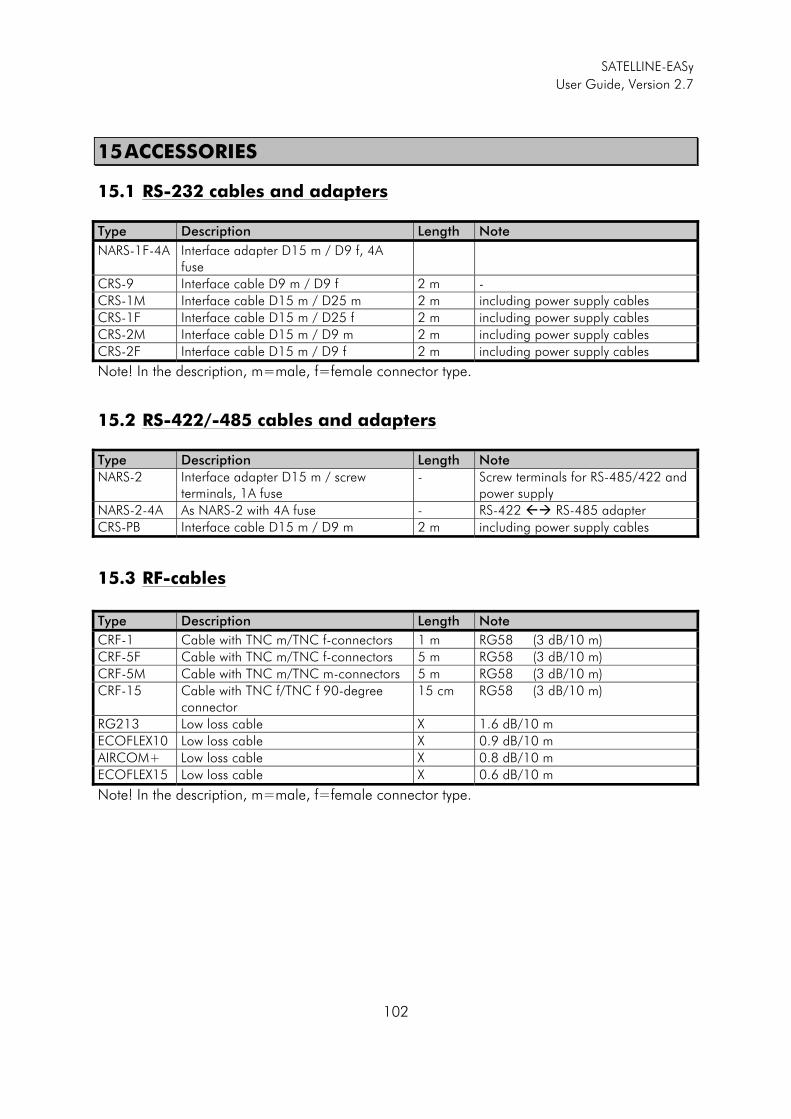
SATELLINE-EASy
User Guide, Version 2.7
102
15 ACCESSORIES
15.1 RS-232 cables and adapters
Type Description Length Note
NARS-1F-4A Interface adapter D15 m / D9 f, 4A fuse
CRS-9 Interface cable D9 m / D9 f 2 m -
CRS-1M Interface cable D15 m / D25 m 2 m including power supply cables
CRS-1F Interface cable D15 m / D25 f 2 m including power supply cables
CRS-2M Interface cable D15 m / D9 m 2 m including power supply cables
CRS-2F Interface cable D15 m / D9 f 2 m including power supply cables
Note! In the description, m=male, f=female connector type.
15.2 RS-422/-485 cables and adapters
Type Description Length Note
NARS-2 Interface adapter D15 m / screw terminals, 1A fuse
- Screw terminals for RS-485/422 and power supply
NARS-2-4A As NARS-2 with 4A fuse - RS-422 �� RS-485 adapter
CRS-PB Interface cable D15 m / D9 m 2 m including power supply cables
15.3 RF-cables
Type Description Length Note
CRF-1 Cable with TNC m/TNC f-connectors 1 m RG58 (3 dB/10 m)
CRF-5F Cable with TNC m/TNC f-connectors 5 m RG58 (3 dB/10 m)
CRF-5M Cable with TNC m/TNC m-connectors 5 m RG58 (3 dB/10 m)
CRF-15 Cable with TNC f/TNC f 90-degree connector
15 cm RG58 (3 dB/10 m)
RG213 Low loss cable X 1.6 dB/10 m
ECOFLEX10 Low loss cable X 0.9 dB/10 m
AIRCOM+ Low loss cable X 0.8 dB/10 m
ECOFLEX15 Low loss cable X 0.6 dB/10 m
Note! In the description, m=male, f=female connector type.
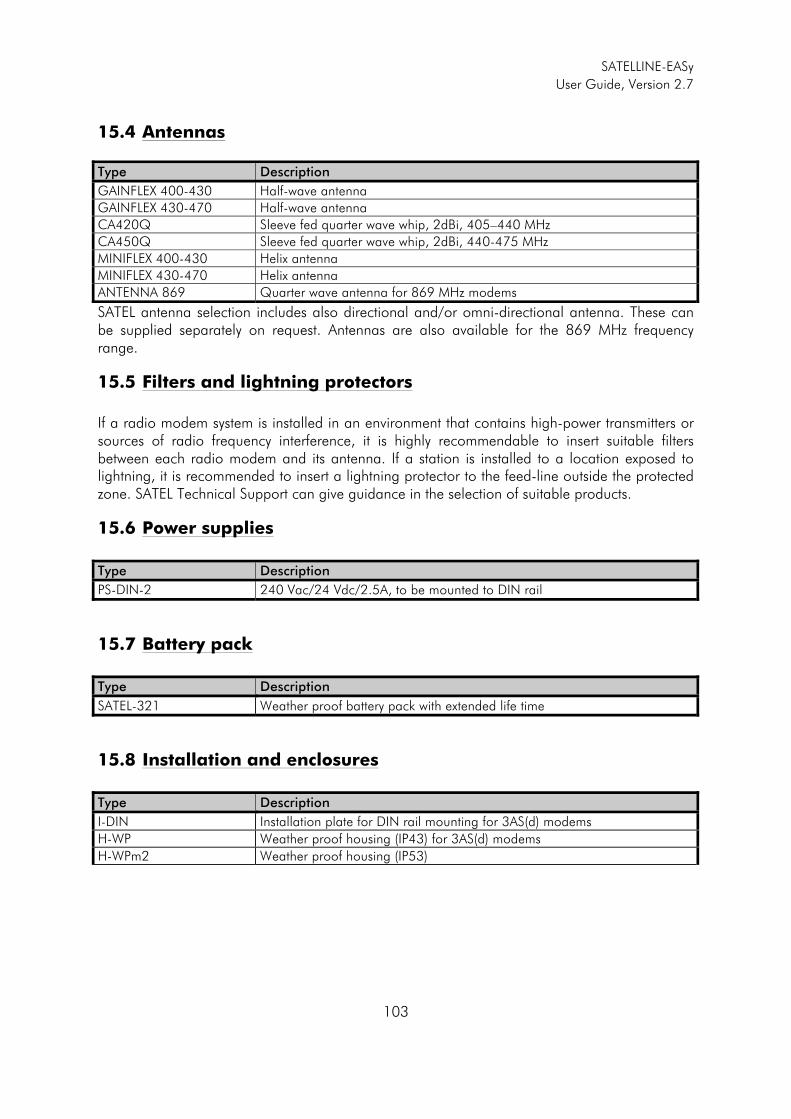
SATELLINE-EASy
User Guide, Version 2.7
103
15.4 Antennas
Type Description
GAINFLEX 400-430 Half-wave antenna
GAINFLEX 430-470 Half-wave antenna
CA420Q Sleeve fed quarter wave whip, 2dBi, 405–440 MHz
CA450Q Sleeve fed quarter wave whip, 2dBi, 440-475 MHz
MINIFLEX 400-430 Helix antenna
MINIFLEX 430-470 Helix antenna
ANTENNA 869 Quarter wave antenna for 869 MHz modems
SATEL antenna selection includes also directional and/or omni-directional antenna. These can be supplied separately on request. Antennas are also available for the 869 MHz frequency range.
15.5 Filters and lightning protectors
If a radio modem system is installed in an environment that contains high-power transmitters or sources of radio frequency interference, it is highly recommendable to insert suitable filters between each radio modem and its antenna. If a station is installed to a location exposed to lightning, it is recommended to insert a lightning protector to the feed-line outside the protected zone. SATEL Technical Support can give guidance in the selection of suitable products.
15.6 Power supplies
Type Description
PS-DIN-2 240 Vac/24 Vdc/2.5A, to be mounted to DIN rail
15.7 Battery pack
Type Description
SATEL-321 Weather proof battery pack with extended life time
15.8 Installation and enclosures
Type Description
I-DIN Installation plate for DIN rail mounting for 3AS(d) modems
H-WP Weather proof housing (IP43) for 3AS(d) modems
H-WPm2 Weather proof housing (IP53)

SATELLINE-EASy
User Guide, Version 2.7
104
16 APPENDIX A
ASCII CHARACTER TABLE
D H A D H A D H A D H A D H A D H A
0 0 NUL 43 2B + 86 56 V 129 81 172 AC 215 D7 1 1 SOH 44 2C , 87 57 W 130 82 173 AD 216 D8 2 2 STX 45 2D - 88 58 X 131 83 174 AE 217 D9 3 3 ETX 46 2E . 89 59 Y 132 84 175 AF 218 DA 4 4 EOT 47 2F / 90 5A Z 133 85 176 B0 219 DB 5 5 ENQ 48 30 0 91 5B [ 134 86 177 B1 220 DC 6 6 ACK 49 31 1 92 5C \ 135 87 178 B2 221 DD 7 7 BEL 50 32 2 93 5D ] 136 88 179 B3 222 DE 8 8 BS 51 33 3 94 5E ^ 137 89 180 B4 223 DF 9 9 HT 52 34 4 95 5F _ 138 8A 181 B5 224 E0
10 A LF 53 35 5 96 60 ` 139 8B 182 B6 225 E1 11 B VT 54 36 6 97 61 a 140 8C 183 B7 226 E2 12 C FF 55 37 7 98 62 b 141 8D 184 B8 227 E3 13 D CR 56 38 8 99 63 c 142 8E 185 B9 228 E4 14 E SO 57 39 9 100 64 d 143 8F 186 BA 229 E5 15 F SI 58 3A : 101 65 e 144 90 187 BB 230 E6 16 10 DLE 59 3B ; 102 66 f 145 91 188 BC 231 E7 17 11 DC1 60 3C < 103 67 g 146 92 189 BD 232 E8 18 12 DC2 61 3D = 104 68 h 147 93 190 BE 233 E9 19 13 DC3 62 3E > 105 69 i 148 94 191 BF 234 EA 20 14 DC4 63 3F ? 106 6A j 149 95 192 C0 235 EB 21 15 NAK 64 40 @ 107 6B k 150 96 193 C1 236 EC 22 16 SYN 65 41 A 108 6C l 151 97 194 C2 237 ED 23 17 ETB 66 42 B 109 6D m 152 98 195 C3 238 EE 24 18 CAN 67 43 C 110 6E n 153 99 196 C4 239 EF 25 19 EM 68 44 D 111 6F o 154 9A 197 C5 240 F0 26 1A SUB 69 45 E 112 70 p 155 9B 198 C6 241 F1 27 1B ESC 70 46 F 113 71 q 156 9C 199 C7 242 F2 28 1C FS 71 47 G 114 72 r 157 9D 200 C8 243 F3 29 1D GS 72 48 H 115 73 s 158 9E 201 C9 244 F4 30 1E RS 73 49 I 116 74 t 159 9F 202 CA 245 F5 31 1F US 74 4A J 117 75 u 160 A0 203 CB 246 F6 32 20 SP 75 4B K 118 76 v 161 A1 204 CC 247 F7 33 21 ! 76 4C L 119 77 w 162 A2 205 CD 248 F8 34 22 " 77 4D M 120 78 x 163 A3 206 CE 249 F9 35 23 # 78 4E N 121 79 y 164 A4 207 CF 250 FA 36 24 $ 79 4F O 122 7A z 165 A5 208 D0 251 FB 37 25 % 80 50 P 123 7B { 166 A6 209 D1 252 FC 38 26 & 81 51 Q 124 7C | 167 A7 210 D2 253 FD 39 27 ' 82 52 R 125 7D } 168 A8 211 D3 254 FE 40 28 ( 83 53 S 126 7E ~ 169 A9 212 D4 255 FF 41 29 ) 84 54 T 127 7F 170 AA 213 D5 42 2A * 85 55 U 128 80 171 AB 214 D6
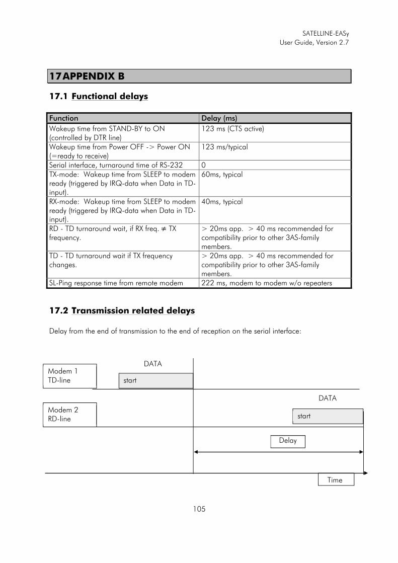
SATELLINE-EASy
User Guide, Version 2.7
105
17 APPENDIX B
17.1 Functional delays
Function Delay (ms)
Wakeup time from STAND-BY to ON(controlled by DTR line)
123 ms (CTS active)
Wakeup time from Power OFF -> Power ON (=ready to receive)
123 ms/typical
Serial interface, turnaround time of RS-232 0 TX-mode: Wakeup time from SLEEP to modem ready (triggered by IRQ-data when Data in TD-input).
60ms, typical
RX-mode: Wakeup time from SLEEP to modem ready (triggered by IRQ-data when Data in TD-input).
40ms, typical
RD - TD turnaround wait, if RX freq.�� TX frequency.
> 20ms app. > 40 ms recommended for compatibility prior to other 3AS-family members.
TD - TD turnaround wait if TX frequency changes.
> 20ms app. > 40 ms recommended for compatibility prior to other 3AS-family members.
SL-Ping response time from remote modem 222 ms, modem to modem w/o repeaters
17.2 Transmission related delays
Delay from the end of transmission to the end of reception on the serial interface:
Modem 1 TD-line
Modem 2 RD-line
Delay
Time
start
start
DATA
DATA
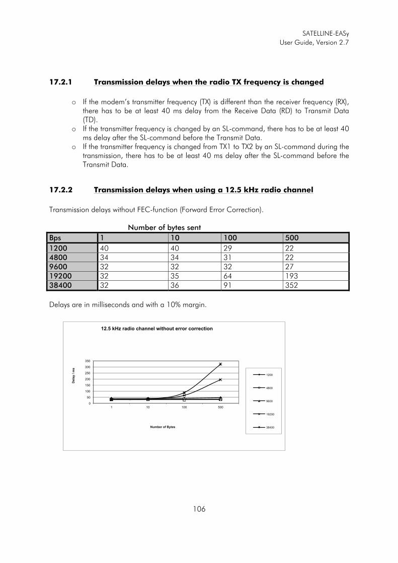
SATELLINE-EASy
User Guide, Version 2.7
106
17.2.1 Transmission delays when the radio TX frequency is changed
o If the modem’s transmitter frequency (TX) is different than the receiver frequency (RX),
there has to be at least 40 ms delay from the Receive Data (RD) to Transmit Data (TD).
o If the transmitter frequency is changed by an SL-command, there has to be at least 40 ms delay after the SL-command before the Transmit Data.
o If the transmitter frequency is changed from TX1 to TX2 by an SL-command during the transmission, there has to be at least 40 ms delay after the SL-command before the Transmit Data.
17.2.2 Transmission delays when using a 12.5 kHz radio channel
Transmission delays without FEC-function (Forward Error Correction). Number of bytes sent
Bps 1 10 100 500
1200 40 40 29 22 4800 34 34 31 22 9600 32 32 32 2719200 32 35 64 193 38400 32 36 91 352
Delays are in milliseconds and with a 10% margin.
0
50
100
150
200
250
300
350
1 10 100 500
Dela
y / m
s
Number of Bytes
12.5 kHz radio channel without error correction
1200
4800
9600
19200
38400
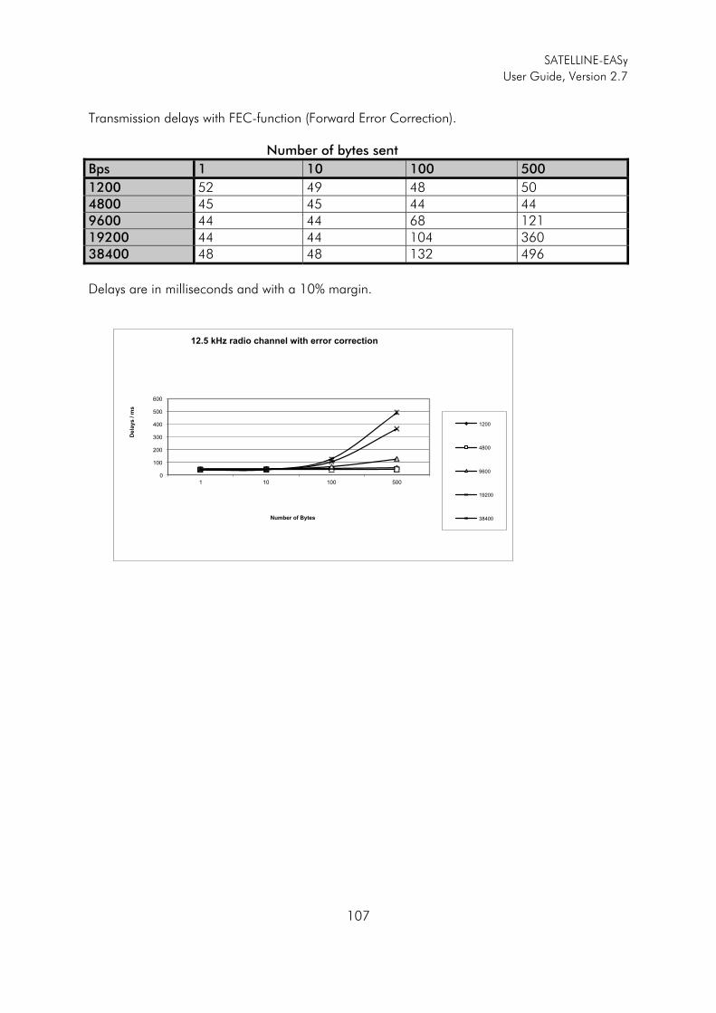
SATELLINE-EASy
User Guide, Version 2.7
107
Transmission delays with FEC-function (Forward Error Correction). Number of bytes sent
Bps 1 10 100 500
1200 52 49 48 50 4800 45 45 44 44 9600 44 44 68 121 19200 44 44 104 360 38400 48 48 132 496
Delays are in milliseconds and with a 10% margin.
0
100
200
300
400
500
600
1 10 100 500
Dela
ys / m
s
Number of Bytes
12.5 kHz radio channel with error correction
1200
4800
9600
19200
38400
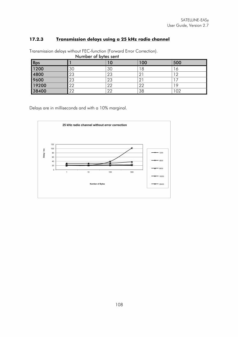
SATELLINE-EASy
User Guide, Version 2.7
108
17.2.3 Transmission delays using a 25 kHz radio channel
Transmission delays without FEC-function (Forward Error Correction). Number of bytes sent
Bps 1 10 100 500
1200 30 30 18 16 4800 23 23 21 12 9600 23 23 21 17 19200 22 22 22 19 38400 22 22 38 102
Delays are in milliseconds and with a 10% marginal.
0
20
40
60
80
100
120
1 10 100 500
Dela
y / m
s
Number of Bytes
25 kHz radio channel without error correction
1200
4800
9600
19200
38400
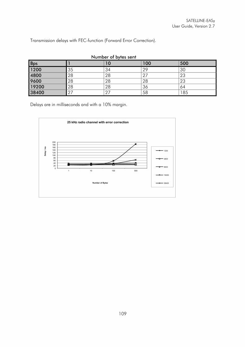
SATELLINE-EASy
User Guide, Version 2.7
109
Transmission delays with FEC-function (Forward Error Correction). Number of bytes sent
Bps 1 10 100 500
1200 35 34 29 30 4800 28 28 27 23 9600 28 28 28 23 19200 28 28 36 64 38400 27 27 58 185
Delays are in milliseconds and with a 10% margin.
0
20
40
60
80
100
120
140
160
180
200
1 10 100 500
Dela
y / m
s
Number of Bytes
25 kHz radio channel with error correction
1200
4800
9600
19200
38400