satellite stabilization
TRANSCRIPT

8/7/2019 Satellite Stabilization
http://slidepdf.com/reader/full/satellite-stabilization 1/4
8/7/2019 Satellite Stabilization
http://slidepdf.com/reader/full/satellite-stabilization 2/4
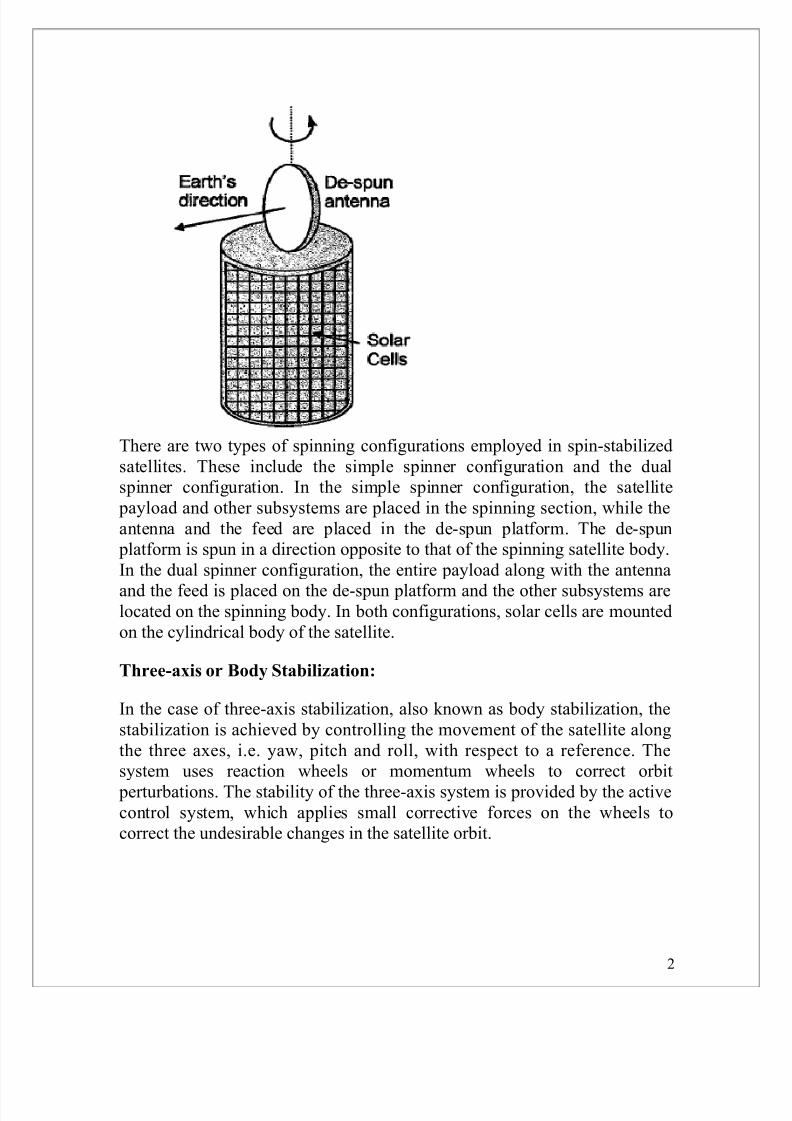
There are two types of spinning configurations employed in spin-stabilizedsatellites. These include the simple spinner configuration and the dualspinner configuration. In the simple spinner configuration, the satellitepayload and other subsystems are placed in the spinning section, while theantenna and the feed are placed in the de-spun platform. The de-spunplatform is spun in a direction opposite to that of the spinning satellite body.In the dual spinner configuration, the entire payload along with the antennaand the feed is placed on the de-spun platform and the other subsystems arelocated on the spinning body. In both configurations, solar cells are mountedon the cylindrical body of the satellite.
Three-axis or Body Stabilization:
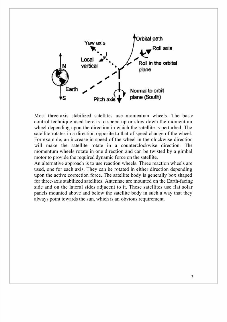
In the case of three-axis stabilization, also known as body stabilization, thestabilization is achieved by controlling the movement of the satellite alongthe three axes, i.e. yaw, pitch and roll, with respect to a reference. Thesystem uses reaction wheels or momentum wheels to correct orbitperturbations. The stability of the three-axis system is provided by the activecontrol system, which applies small corrective forces on the wheels tocorrect the undesirable changes in the satellite orbit.
2
8/7/2019 Satellite Stabilization
http://slidepdf.com/reader/full/satellite-stabilization 3/4
Most three-axis stabilized satellites use momentum wheels. The basiccontrol technique used here is to speed up or slow down the momentumwheel depending upon the direction in which the satellite is perturbed. Thesatellite rotates in a direction opposite to that of speed change of the wheel.For example, an increase in speed of the wheel in the clockwise directionwill make the satellite rotate in a counterclockwise direction. Themomentum wheels rotate in one direction and can be twisted by a gimbalmotor to provide the required dynamic force on the satellite.An alternative approach is to use reaction wheels. Three reaction wheels are
used, one for each axis. They can be rotated in either direction dependingupon the active correction force. The satellite body is generally box shapedfor three-axis stabilized satellites. Antennae are mounted on the Earth-facingside and on the lateral sides adjacent to it. These satellites use flat solar panels mounted above and below the satellite body in such a way that theyalways point towards the sun, which is an obvious requirement.
3

8/7/2019 Satellite Stabilization
http://slidepdf.com/reader/full/satellite-stabilization 4/4
Comparison between Spin-stabilized and Three-axis Stabilized Satellites
1. In comparison to spin-stabilized satellites, three-axis stabilized satelliteshave more power generation capability and more additional mounting areaavailable for complex antennae structures.2. Spin-stabilized satellites are simpler in design and less expensive thanthree-axis stabilized satellites.3. Three-axis stabilized satellites have the disadvantage that the extendiblesolar array used in these satellites is unable to provide power when thesatellite is in the transfer orbit, as the array is still stored inside the satelliteduring this time.
4