satellite subsystems - wordpress.com · communication subsystems ... 4 this subsystem ... signal...
TRANSCRIPT

SATELLITE SUBSYSTEMS
Dr. Marwah Ahmed Networks and
Communication
Department
1
Outlines
Attitude and Orbit Control System (AOCS)
Telemetry, Tracking, Command and Monitoring
(TTC & M)
Power System
Communication Subsystems - Transponders
Satellite Antennas

Satellite Communications, 2/E by
Timothy Pratt, Charles Bostian, &
Jeremy Allnutt
Copyright © 2003 John Wiley & Sons.
Inc. All rights reserved.
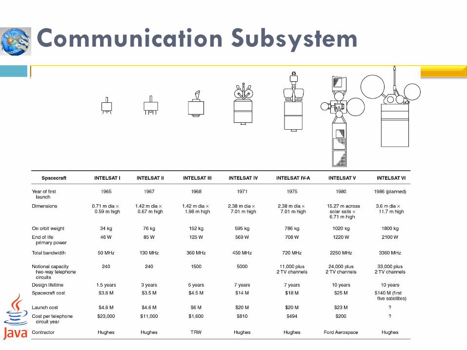
Figure 3.1 (p. 58)
Exploded view of a spinner satellite
based on the Boeing (Hughes) HS 376
design. INTELSAT IVA (courtesy of
Intelsat).
Attitude and Orbit Control System
(AOCS)
26-May-16 Networks and Communication Department
4
This subsystem consists of rocket motors that are
used to move the satellite back to the correct orbit
when external forces cause it to drift off station and
gas jets or inertial devices that control the attitude
of the satellite.
Telemetry, Tracking, Command and
Monitoring (TTC & M)
26-May-16 Networks and Communication Department
5
These systems are partly on the satellite and partly
at the controlling earth station.
The telemetry system sends data derived from
many sensors on the satellite, which monitor the
satellite’s health, via a telemetry link to the
controlling earth station.
The tracking system is located at this earth station
and provides information on the range and the
elevation and azimuth angles of the satellite.

Telemetry, Tracking, Command and
Monitoring (TTC & M)
26-May-16 Networks and Communication Department
6
Based on telemetry data received from the satellite
and orbital data obtained from the tracking system,
the control system is used to correct the position
and attitude of the satellite. It is also used to control
the antenna pointing and communication system
configuration to suit current traffic requirements,
and to operate switches on the satellite.

Satellite Communications, 2/E by Timothy Pratt, Charles Bostian, & Jeremy Allnutt
Copyright © 2003 John Wiley & Sons. Inc. All rights reserved.
Figure 3.8 (p. 69) Typical tracking, telemetry, command and monitoring
system.

Telemetry, Tracking, Command and
Monitoring (TTC & M)
Essential to the successful operation of a communication satellite
Main function control the orbit and the attitude of the satellite,
monitor the status of all sensors and subsystem on the satellite
switch on and off of the communication system
Owned and operated by satellite owner
For large GEO Satellites repointing of individual antennas may be possible
Tracking is perform by earth station

Telemetry, Tracking, Command and
Monitoring (TTC & M)
The command system is used to make changes in attitudes and corrections to the orbit
to control the communication system
The command and telemetry links are separate from the communication system, although they may operate in the same frequency band
Used to eject the satellite from geostationary orbit and to switch off all transmitters when the satellite reaches the end of its life.

Power System
All communications satellites derive their electrical power from solar cells
Solar cells convert incident sunlight into electrical energy
Spin stabilized satellite has a cylindrical body covered in solar cells
For flat panels cells can be rotated to maintain normal incidence of the sunlight.
The satellite must carry batteries to power the subsystem during launch and during night

Communications Subsystems The communication subsystem is the major component of a
communications satellite, and the remainder of the satellite is there solely to support it.
Provide platform for relaying of voice, video, and data communication.
The satellite transponders have limited output power
The received power level even with large aperture earth station antenna is very small and rarely exceed 10-10W
For the system to perform satisfactorily, the signal power must exceed the power of the noise generated in the receiver by between 5 and 25 dB depending on the bandwidth of the transmitted signal and the modulation scheme used.
With low power transmitter, narrow receiver bandwidth have to be used to maintain the required signal-to-noise ratios.

Communication Subsystem
Large GEO satellites use both 6/4 GHz and 14/12 GHz bands
Satellite systems designed for Ku band and Ka band have narrower antenna beams, and better control of the coverage patterns than satellite using C bands.
At Ku band and Ka band propagation in rain becomes a major factor and attenuation in rain increases at the square of the frequency.
At 20GHz rain attenuation is four times larger, in dB, than 10GHz.
Communication Subsystem

Transponders
26-May-16
15
Networks and Communication Department

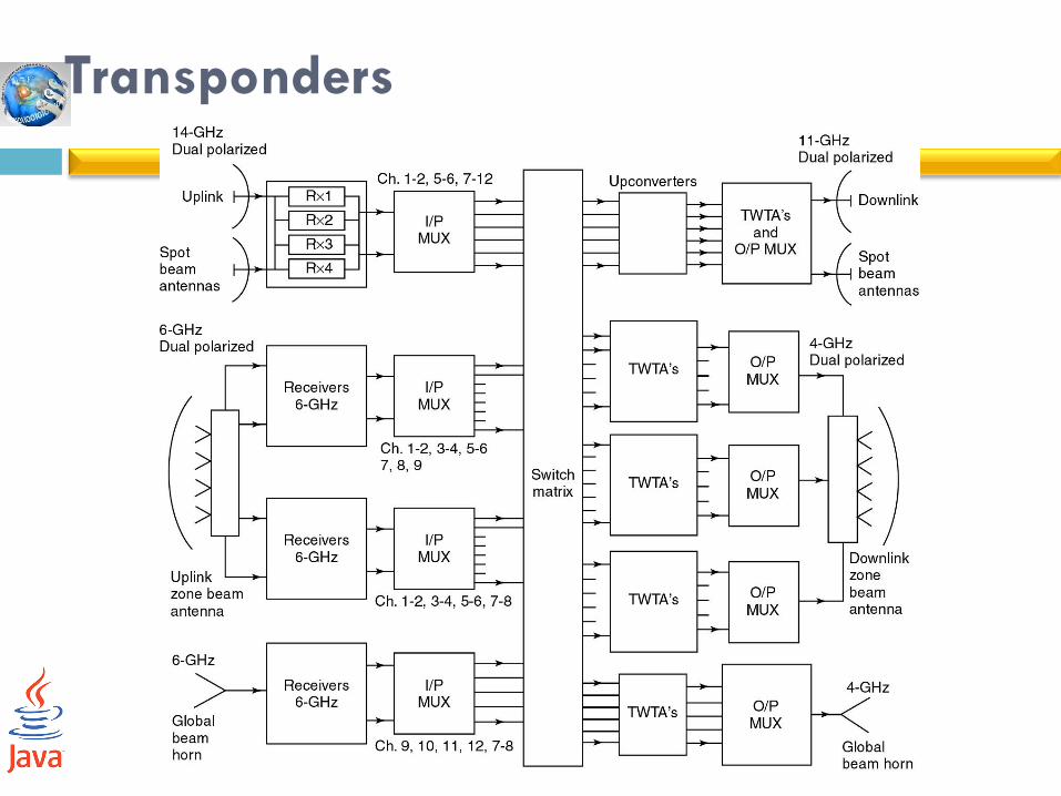
Transponders
Signal transmitted by an earth station are received at the satellite by either zone beam or spot beam antenna
Zone beam can received from transmitters anywhere within the coverage zone, whereas spot beam have limited coverage
A transponder consists of a bandpss filter to select the particular channel, downconverter to change the frequency from 6GHz at the input to 4GHz at the output
Communication system has many transponders some of which may be spares

Transponders
The transponders are supplied with signals from one or more receive antennas and send their output to a switch matrix that directs each transponder band of frequencies to appropriate antenna
In a large satellite there may be four or five beams to which any transponder can be connected.
The switch setting can be controlled from the earth to allow reallocation of the transponders between the downlink beams as traffic pattern change
Transponders
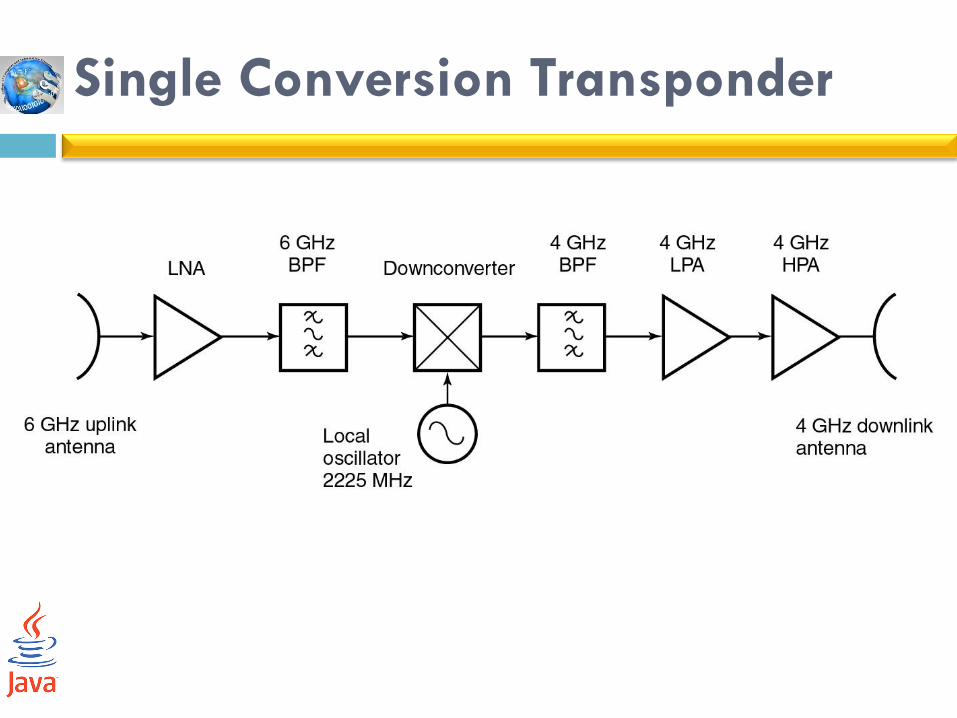
Single Conversion Transponder

Single Conversion Transponder
The output power amplifier is usually a solid state power amplifier (SSPA) unless a very high power ( > 50 W) is required where travelling wave tube amplifier (TWTA) would be used.
Local oscillator is at 2225 MHz to provide shift in frequency from 6GHz uplink frequency to the 4 GHz downlink frequency.
The bandpass filter after the mixer removes unwanted frequencies resulting from the down conversion operation.
The attenuator can be controlled via the uplink command system to set the gain of the transponder.
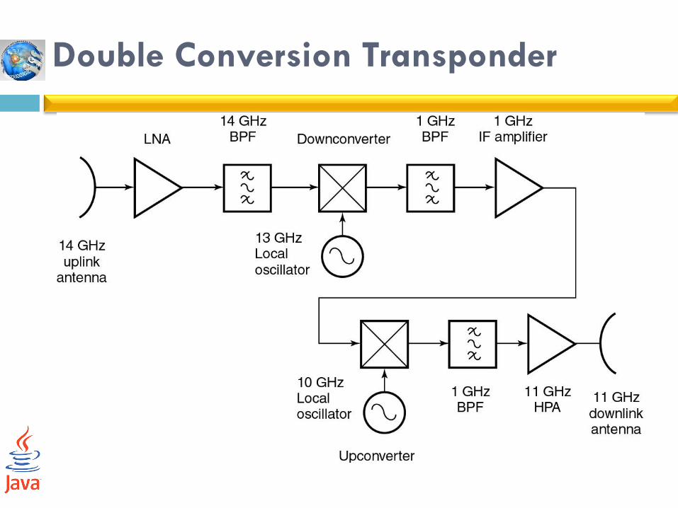
Double Conversion Transponder

Double Conversion Transponder
Transponder use in 14/11 GHz bands normally employ a double frequency conversion scheme.
It is easier to make filters, amplifiers and equalizers at an intermediate frequency (IF) such as 1100 MHz than at 14 GHz or 11 GHz.
The incoming 14 GHz carrier is translated to an IF of around 1 GHz.
The amplification and filtering are performed at 1GHz and a relatively high level carrier is translated back to 11 GHz for amplification by the HPA
Stringent requirements are placed on the filters used in transponders, since must they must provide good rejection of unwanted frequencies.
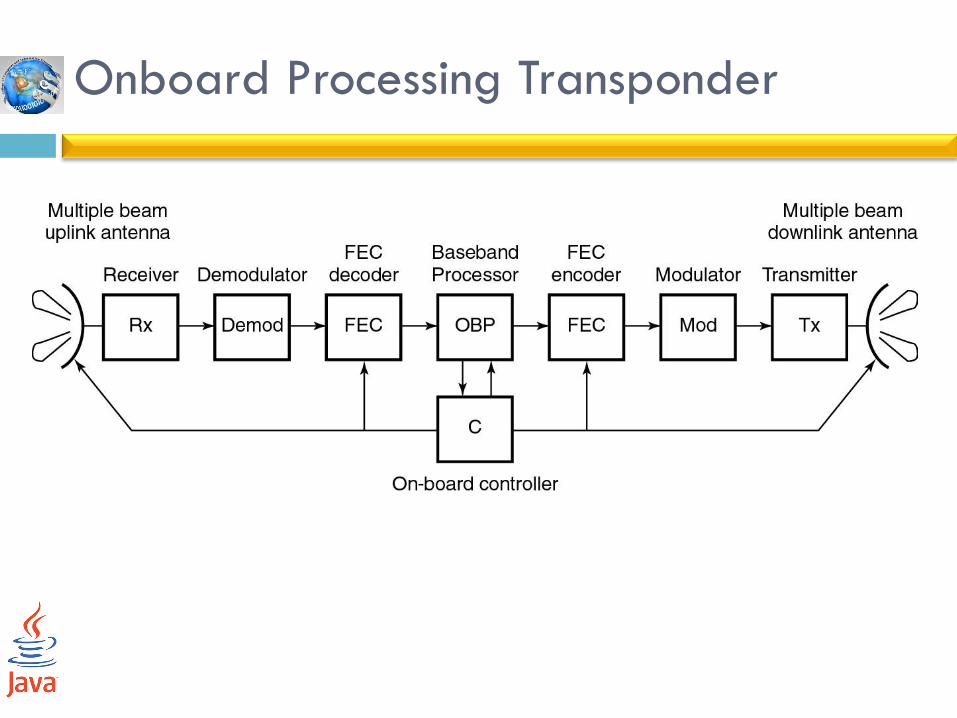
Onboard Processing Transponder
Onboard Processing Transponder
Communication capacity of the satellite can be achieved by combining onboard processing with switched beam technology.
A switched beam satellite generates a narrow transmit beam for each earth station
Then it transmits sequentially to each one using time division multiplexing of the signal
Narrow beam has to cover only one earth station allowing the satellite transmit antenna to have a very high gain compared to a zone coverage antenna.
Onboard Processing Transponder
The high gain antennas used in switched beam systems raise the EIRP of the satellite transmitter
This will increase the capacity of the downlink.
Switched beam systems on GEO satellites work best at Ku band where the wavelength is short enough
This allow antennas with beams of less than 0.40 beamwidth to be generated
Multiple beam antennas with baseband processing transponders are used on GEO and LEO satellites providing services to mobile terminals and handheld telephone.

Satellite Antenna
26-May-16
26
Networks and Communication Department
Satellite Antennas
Main types of antennas are used on satellite: Horn antennas
Reflector antennas
Array antennas
An antenna pattern is a plot of the field strength in the far field
The gain of the antenna is a measure of the antenna’s capability to direct energy in one direction.
A useful principle in antenna theory is reciprocity
Reciprocity means that an antenna has the same gain and pattern whether it transmit or receives.
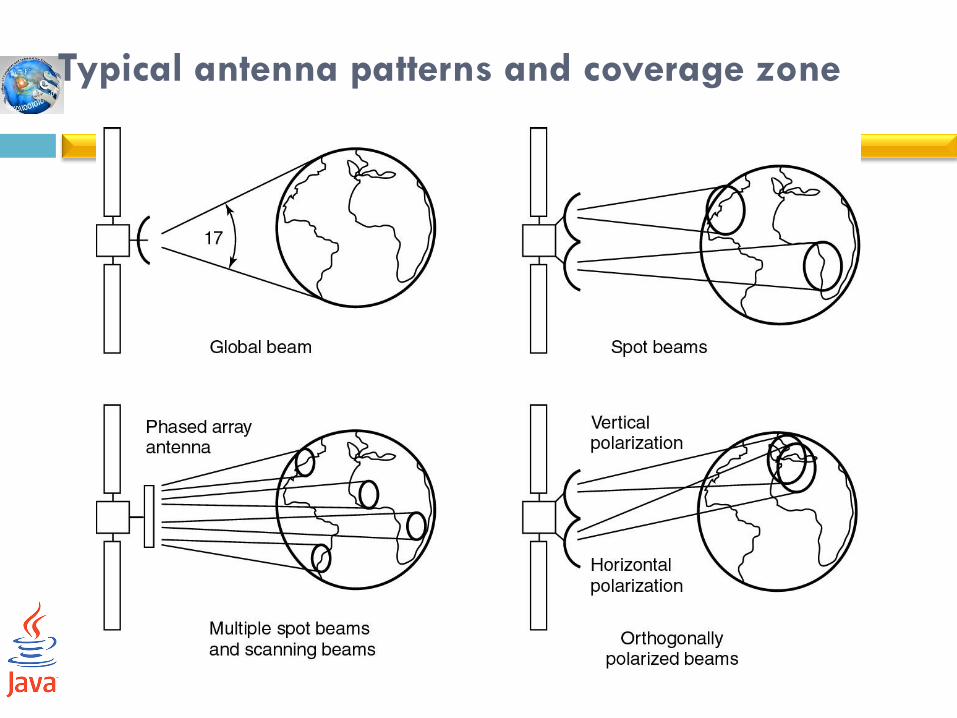
Typical antenna patterns and coverage zone

Contours of Antenna Gain

Horn Antennas
Horn antennas are used at microwave frequencies when wide beams are required as for global coverage.
A horn is a flared section of waveguide that provides an aperture several wavelengths wide and a good match between the waveguide impedance and free space.
Horn are also used as feeds for reflectors, either singly or in clusters.
Horns and reflectors are examples of aperture antennas that launch a wave into free space from a wavegiude.

Reflector Antennas
Reflector antennas are illuminated by one or more horns and provide a larger aperture than can be achieved with a horn.
The parabolic is the basic shape for most reflector antenna and commonly used by the earth station antennas.
Satellite antennas use modified parabolic reflector profile to tailor the beam pattern to a particular coverage zone.
Phased Array Antennas
Phased array antennas are used on satellites to
create multiple beams from a single aperture.
Been used by Iridium and Globarstar to generate
multiple beams from a single aperture for their LEO
mobile telephone systems
Aperture Antenna
Aperture antenna has a gain G:
G = 𝜂4𝜋𝐴
𝜆2
Where A = area of the antenna aperture in m2
λ = wavelength
η = aperture efficiency
(η = 55 to 65 % for reflector antenna and 65 to 80% for
horn antenna)
Circular Aperture Antenna
If the aperture is circular:
G = η(╥D/λ)2
Where D = diameter of the circular aperture
Beamwidth of the circular aperture antenna
θ3dB = 75 λ/D degree
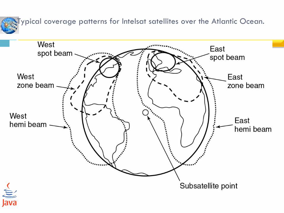
Typical coverage patterns for Intelsat satellites over the Atlantic Ocean.

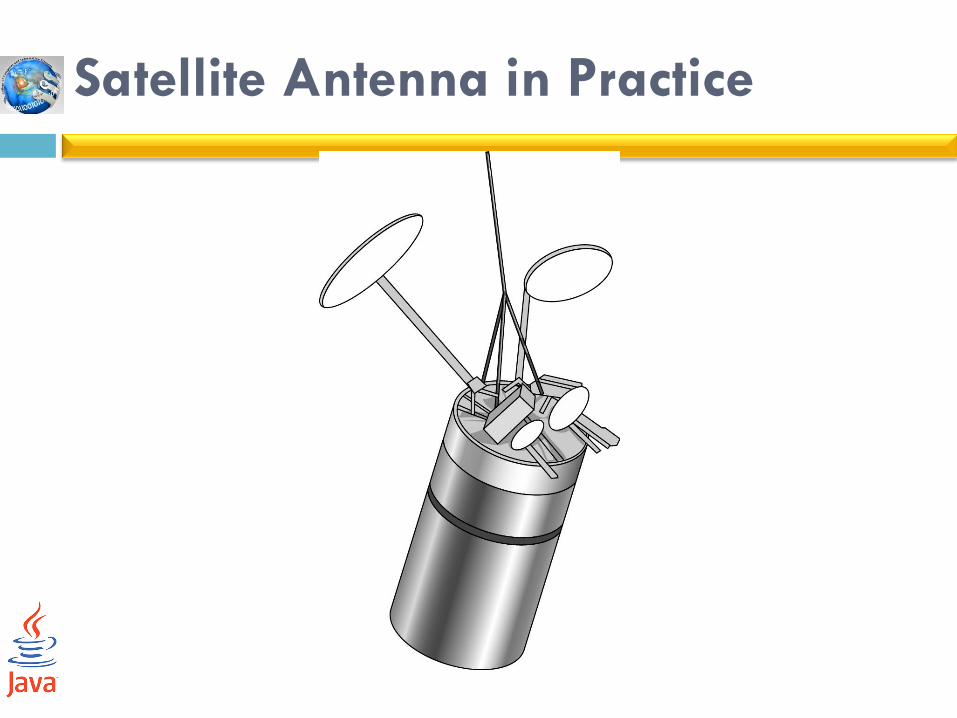
Satellite Antenna in Practice
The largest reflector on the satellite transmits at 4GHz and produced the peanut shaped patterns for the zone beams.
It is designed to concentrated the transmitted energy onto densely populated areas where much of the telecommunication traffic is generated.
Smaller antennas are used to provide hemisphere transmit and receive beams and spot beams.
Horn antenna providing global beam coverage
Satellite Antenna in Practice

Deployment of the Antenna
.1After separation
.2Solar array boom extended
.3Solar array panels extended
.4Reflector deploys
.5Fully deployed configuration
1 2 3
4 5

Deployment of the Antenna
Antenna was built as a series of petals that folded
over each other to make a compact unit during
launch, which then unfurled in orbit
The solar sails folded down over antenna and were
deployed first.
Springs devices can be used to provide the energy
for deployment of antennas or solar sails