sb1223.1 usa en 2009-10-07 - abc companies
TRANSCRIPT

SB1223.1_USA_en_2009-10-07 Page 1 of 10
ADDRESSEES : ABC Customer Care and Parts Source
COACH/BUS MODEL : C2045
BULLETIN TYPE : Product Improvement
SECTION/CHAPTER : Section 11 – Body and accessories Chapter 10.54 Exterior parts
DATE : October 7, 2009
SUBJECT : Thermoplastic rear bumper – to address distortion issues
TERMS & CONDITIONS : -
APPLICATION : The product improvement mentioned in this Bulletin can be retrofitted to following units:
Model Engine VIN Cummins 45222 � 45499, 46001 � 46103
Detroit Diesel 45686 � 45999, 46501 � 46788 C2045 Caterpillar 47001 � 47527
DESCRIPTION: 1. Rear bumper distortion has been reported on some of the above-mentioned units after they
had been in service for some time (Figure 1). Description continued on next page.
SERVICE BULLETIN SB1223
Figure 1

SB1223.1_USA_en_2009-10-07 Page 2 of 10
2. Investigation indicates that here are two possible causes for this issue:
• The distortion may be caused by the difference in expansion rate between the thermoplastic bumper shell and the aluminum back-up beam to which it is bolted. When the shell has been secured too tightly to the beam and the ambient temperature rises considerably, the travel of the faster expanding shell is restricted by the slower expanding beam, resulting in buckling of the shell.
• The above-mentioned process may be magnified by the heat from the exhaust tailpipe(s), and to a lesser degree by the heat radiating from the engine.
3. NOTE: 2008 model coaches have an EPA 07 engine and an automatic regeneration system for
the Diesel Particulate Filter (DPF) that can heat up the tailpipe to 1,500°F. Hence the need to install an exhaust heat shield in order to protect the rear bumper against distortion. The coaches subject of this Bulletin have an EPA 04 motor and don’t feature the DPF system. Their tailpipe reaches a temperature that is only approximately 800°F. As both 2008 and pre-2008 model coaches share the same rear bumper the exhaust heat shield may be retrofitted to great effect. NOTE: The installation of a heat shield is compulsory when a distorted rear bumper is being replaced under warranty.
This Service Bulletin has been released so distortion issues can be addressed by applying one or more of the procedures listed below. • The first procedure explains how to check that the shell has been properly attached to the
back-up beam and what should be done to correct the installation. • The second procedure provides instructions on how to install an exhaust heat shield similar
to the one that is standard equipment on model 2008 coaches (Figure 2). • The third procedure shows how a finisher can be fitted to the top section of the bumper as a
reinforcement and stiffener (Figure 3), should distortion hamper the opening of the engine compartment door.
• For your information, the exhaust heat shield has been cut into production as from units
46104 �, 46789 �, and 47528 �. • Customers who want to equip their coaches with the 2008 model heat shield as a
preventive measure may purchase the parts and install them as described in this Bulletin.
Figure 2 Figure 3

SB1223.1_USA_en_2009-10-07 Page 3 of 10
PARTS AND PRODUCTS : Retrofit parts VH reference Description Qty. VH 11086035 Heat shield, flat, to fit on top of tailpipe 1 VH 11083739 Heat shield, curved, to fit into rear bumper recess 1 VH 660229757 Bolt, M6 x 1 x 30 mm, stainless, grade A2 2 VH 660623508 Flat washer, M6, stainless, grade A2 2 VH 660636302 Lock washer, M6, stainless, grade A2 2 VH 660209922 Nut, M6, stainless, grade A2 2 VH 11105209 Finisher, rear bumper reinforcing 1
• Parts may be purchased from your nearest ABC Customer Care & Parts Source service center. • Parts/Waste disposal: discard old parts and products according to applicable environmental
regulations.
PROCEDURE: To address distortion issues 1. General :
• Job allocation:
Personnel Job Qualifications Number required
Remove rear bumper. Reinstall bumper.
2
Fit exhaust heat shield. Fit garnish molding.
Body repair 1
• For more information refer to: the Maintenance Manual, the Spare Parts Manual, and the
Operating Manual. 2. Special tools, equipment or services :
This job requires the use of:
VH reference Description Local sourcing Torque wrench, ranging up to 135 ft.lbf (180 Nm) Local sourcing Socket, metric, 24 mm
3. Preparations :
• Park the coach on a level surfaced service pit with the front wheels straight. If portable post lifts are going to be used, lower the suspension first. Apply the parking brake and shut down the engine.
• Switch off all systems and turn off the battery master switch. • Put a “DO NOT OPERATE” tag on the instrument panel. • Read the entire procedure before beginning to work.

SB1223.1_USA_en_2009-10-07 Page 4 of 10
4. To remove the rear bumper assembly :
NOTE: The bumper assembly is attached to the chassis through four rubber springs and comprises of an aluminum back-up beam and a thermoplastic shell.
CAUTION: When working in the engine compartment, turn the starter motor inhibitor switch to “starter motor disabled”. CAUTION: Observe safe shop practices at all times. 1) Open the engine compartment door.
If the door cannot be opened, work from underneath the coach Install tripod stands beneath the bumper, or use a hoist and slings to support the assembly.
2) In the engine compartment, locate the rubber springs, two on the left hand side and two on
the right hand side, which have been fitted between the bumper assembly and the chassis (Figure 4). Unhook the check straps (1, Figure 5). Undo and remove the M16 self-locking nuts securing the bumper assembly to the chassis (2, Figure 5).
3) With the aid of an assistant, lift the bumper off the coach and place it upside down on a
suitable work surface covered with cardboard, so as not to damage the paintwork. Continued on next page.
Figure 4
1
Figure 5
2

SB1223.1_USA_en_2009-10-07 Page 5 of 10
5. To check the bumper shell fastener installation : 1) Check that the retaining nuts and washers have been properly installed.
The purpose is to make sure that that shell is anchored to the beam at the center and that movement is allowed at the ends.
� The fasteners should be fitted in the right order as shown in Figure 6. � The fasteners in the center (Figure 7) should be tightly secured. � The fasteners next to the left- and right-hand V blocks (Figure 8) should be tightened so
that the washers fitted between the nut and the beam can hardly be shifted by hand.
2) If required, tighten the nuts in the center as follows:
� Run-up the nuts and compress the washers until they can no longer be shifted by hand. � Tighten each nut further through 180°.
The conical washers are now properly tightened.
3) If required, tighten the nuts next to the V-blocks by running them up compressing the washers until they can hardly be shifted by hand.
Figure 8
VH10745959
VH660629106
VH660207107
Figure 6
Figure 7
Conical washer – cone should point
towards nut

SB1223.1_USA_en_2009-10-07 Page 6 of 10
6. To reinstall the rear bumper assembly : 1) Reinstall the bumper assembly in reverse order to removal.
Tightening torque for the M16 rubber spring nuts: 135 ft.lbf (180 Nm). 2) Check engine compartment door operation.
7. To retrofit an exhaust heat shield :
Description: Reference is made to Figure 9. The exhaust heat shield sits approximately 9/16” above the tailpipe(s) (1) and comprises of two parts: a flat plate (2) that fits between the left hand rear-most U-channel (3) and the lower lip of the bumper beam (4), and a curved shell (5) that sits under the bumper and bolts to the beam and the flat plate.
1) Working underneath the vehicle remove the tailpipe(s) as follows:
Twin tailpipes (old style): • Slacken the tailpipe clamp fasteners at the muffler. • About two/third way up the tailpipes, undo and remove the clamp fasteners securing the
tailpipes to the chassis-mounted support bracket. • Carefully lever-off the tailpipes.
Continued on next page.
Figure 9
2
3/8”
2 5
1
4 2
3
1
5
SB1223.1_USA_en_2009-10-07 Page 7 of 10
Single tailpipe (new style): • Undo and remove the seal band clamp fasteners at the muffler.
Remove the seal band clamp. • About halfway up the tailpipe, undo and remove the fasteners securing the tailpipe
bracket to the chassis-mounted bracket. • Carefully lever-off the tailpipe.
3) Place the curved shield in the recess of the bumper shell with the heat resisting cloth facing down. Make sure that the mounting lip of the shield rests against the lower lip of the bumper beam, and that there is an 5/8” air gap between the shield and the shell. With a scribe, mark the place of the two slotted holes provided in the shield lip onto the lower lip of the beam. Withdraw the shield. Using the marks of the slotted holes on the lower lip of the beam as a reference, drill a 1/4” diameter hole in the center of each mark.
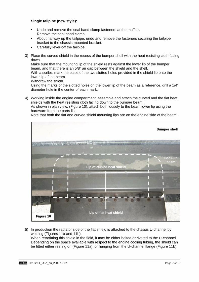
4) Working inside the engine compartment, assemble and attach the curved and the flat heat
shields with the heat resisting cloth facing down to the bumper beam. As shown in plan view, (Figure 10), attach both loosely to the beam lower lip using the hardware from the parts list. Note that both the flat and curved shield mounting lips are on the engine side of the beam.
5) In production the radiator side of the flat shield is attached to the chassis U-channel by welding (Figures 11a and 11b). When retrofitting this shield in the field, it may be either bolted or riveted to the U-channel. Depending on the space available with respect to the engine cooling tubing, the shield can be fitted either resting on (Figure 11a), or hanging from the U-channel flange (Figure 11b).
Figure 10
Bumper shell
Back-up beam
Lip of flat heat shield
Lip of curved heat shield

SB1223.1_USA_en_2009-10-07 Page 8 of 10
6) At the back-up beam, run-up the nuts and tighten the heat shield retaining bolts to a torque
of 80 in.lbf (8.6 Nm).
7) At the U-channel attach the shield by bolting or riveting, whichever is the most suitable.
8) Reinstall the tailpipe(s) in reverse order to removal. Distance from end of tailpipe to edge of bumper (Figure 6): 3/8” (10 mm) Tightening torque for the fasteners: Seal clamp bolts: 50 to 75 ft.lbf (70 to 75 Nm). Clamp to chassis mounting bracket bolts (twin pipe): 30 ft.lbf (40 Nm). Clamp to chassis mounting bracket bolt (single pipe): 15 ft.lbf (20 Nm). Muffler clamp bolts: 30 ft.lbf (40 Nm). Final installation is shown in Figure 2 (single tailpipe shown).
8. To install a reinforcing finisher :
Description: Rear bumper finisher VH 11105209 is a mirror-polished stainless steel reinforcing channel that fits over the top edge of the bumper (Figure 12) and bolts to the rear of the back-up beam (Figures 13a and 13b).
Figure 11a
U-channel
Flat heat shield
Cooling system tubing
Figure 11b
U-channel
Flat heat shield
Cooling system tubing

SB1223.1_USA_en_2009-10-07 Page 9 of 10
1) Reaching behind the bumper, undo and remove the two upper inner most nuts and washers securing the upright rubber spring supports to the back-up beam (1 and 2, Figures 13a and 13b).
2) Trial fit the finisher by placing it over the upper lip of the bumper shell (Figure 14) with the
polished surface facing the engine. The finisher is directional with a tapered section to clear the left-hand bumper springs. This ensures that the finisher sits right in the center of the bumper when installed.
Continued on next page.
Figure 12
Figure 13b
VH 11105209
2
Figure 13a
1
Figure 14

SB1223.1_USA_en_2009-10-07 Page 10 of 10
3) Align the finisher slots with the studs in the back-up beam. If fitting issues arise, the upper edge of the bumper shell may be dressed through careful use of a heat gun. Make sure not to damage the paint.
4) Reinstall the fasteners previously removed. Tighten the nuts to a torque of 15 ft.lbf (21 Nm).
Procedure complete.
DISCLAIMER: The procedures contained herein are not exclusive. Van Hool cannot possibly know, evaluate, or advise the transportation industry of all conceivable ways in which a procedure may be undertaken or of the possible consequences of each such procedure. Other procedures may be as good, or better, depending upon the particular circumstances involved. Each carrier who uses the procedures herein must first satisfy itself thoroughly that neither the safety of its employees or agents, nor the safety or usefulness of any products, will be jeopardized by any procedure selected.
INFORMATION HANDLING : Important supplements to and modifications of the technical information not yet included in the manual, are communicated by means of Service Bulletins. File the Service Bulletins at the back of your manual, in numerical order. To make sure that you will be reminded of the Bulletins that have appeared in the meantime while paging the manual, mark the pages concerned by hand with the Service Bulletin number.