sbd fuel injection assembly and set up ... _set_up...sbd fuel injection assembly and set up...
TRANSCRIPT
SBD FUEL INJECTION ASSEMBLY AND SET UP INSTRUCTIONS TAPER THROTTLE KIT 2.0L 16V
INTRODUCTION
LIST OF COMPONENTS IN YOUR KIT
SBD would like to thank you for choosing the taper throttle injection kit.
The kit was originally developed by Steve at SBD in 1994 for a customer running a privately funded Touring Car, being very pleased with the result obtained he
decided to run a kit on a standard engine. Since then it has proven to be extremely popular in the sprint, circuit and rally scene all around the world. The taper throttle kit is the basis for most of the performance engines and kits produced by SBD and the throttles are also used in the FIA homologated 1997 Opel Astra Mk III kit car kit.
The kits are extremely efficient and as a direct replacement of the standard induction system, give an incredible 39% increase in power (provided a suitable exhaust system is used) and an almost road car like driving characteristic, very
smooth and progressive.
This system is a direct replacement for the Standard GM 2.0L 16V induction system. It does not use the air mass sensor or air filter box that is fitted to the
Standard engine. It fits exactly same as the Standard unit using the same water hose connections. The fuel rail that is fitted to this kit uses a high pressure coupling system called JIC–6. These couplings are specifically designed for use with a high-pressure steel braided fuel hose, which is by far safer to use than a standard rubber fuel hose and has a greater tolerance to damage. It is recommended that you use JIC –6 couplings and steel braided fuel hoses when fitting your system because of
the increased safety element. There are cheaper alternative coupling and hose systems available, but SBD do not consider these safe enough to use in Motorsport
applications.
The wiring looms have been specially designed to be as neat as possible and to cover as many applications as possible. These are wiring looms are kept on the shelf and are available in both front & rear wheel drive applications. Our range of front wheel drive applications will fit most models of Vauxhalls & adaptations can made to allow these harness to suit other manufacturers e.g. Ford. For any other manufacturers, adaptor harnesses may be required. Our rear wheel drive loom is
also suitable for mid engine cars. Custom made harnesses are available, there would be an additional cost and the manufacturing time for a custom made wiring
loom from the time we receive your signed drawing is between 4 & 6 weeks.
When ordering your kit most of the components should be in stock, which means that we can usually despatch your kit immediately.
1
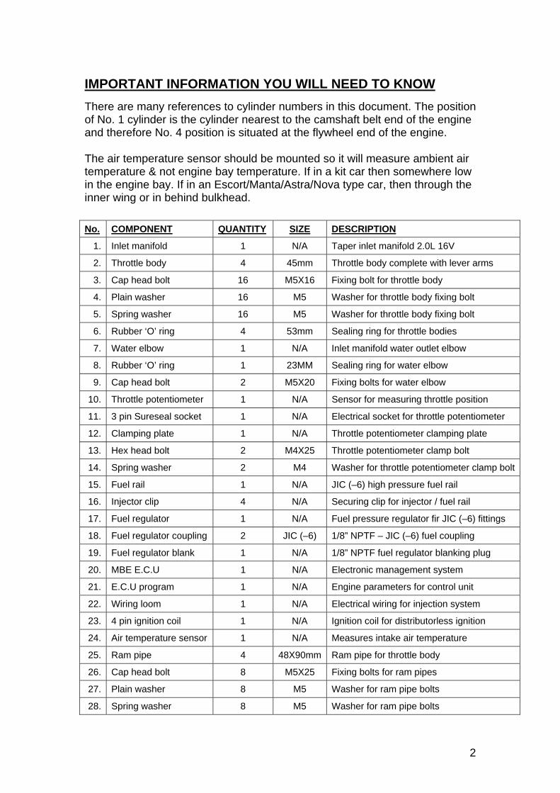
IMPORTANT INFORMATION YOU WILL NEED TO KNOW There are many references to cylinder numbers in this document. The position of No. 1 cylinder is the cylinder nearest to the camshaft belt end of the engine and therefore No. 4 position is situated at the flywheel end of the engine. The air temperature sensor should be mounted so it will measure ambient air temperature & not engine bay temperature. If in a kit car then somewhere low in the engine bay. If in an Escort/Manta/Astra/Nova type car, then through the inner wing or in behind bulkhead.
No. COMPONENT QUANTITY SIZE DESCRIPTION
1. Inlet manifold 1 N/A Taper inlet manifold 2.0L 16V
2. Throttle body 4 45mm Throttle body complete with lever arms
3. Cap head bolt 16 M5X16 Fixing bolt for throttle body
4. Plain washer 16 M5 Washer for throttle body fixing bolt
5. Spring washer 16 M5 Washer for throttle body fixing bolt
6. Rubber ‘O’ ring 4 53mm Sealing ring for throttle bodies
7. Water elbow 1 N/A Inlet manifold water outlet elbow
8. Rubber ‘O’ ring 1 23MM Sealing ring for water elbow
9. Cap head bolt 2 M5X20 Fixing bolts for water elbow
10. Throttle potentiometer 1 N/A Sensor for measuring throttle position
11. 3 pin Sureseal socket 1 N/A Electrical socket for throttle potentiometer
12. Clamping plate 1 N/A Throttle potentiometer clamping plate
13. Hex head bolt 2 M4X25 Throttle potentiometer clamp bolt
14. Spring washer 2 M4 Washer for throttle potentiometer clamp bolt
15. Fuel rail 1 N/A JIC (–6) high pressure fuel rail
16. Injector clip 4 N/A Securing clip for injector / fuel rail
17. Fuel regulator 1 N/A Fuel pressure regulator fir JIC (–6) fittings
18. Fuel regulator coupling 2 JIC (–6) 1/8” NPTF – JIC (–6) fuel coupling
19. Fuel regulator blank 1 N/A 1/8” NPTF fuel regulator blanking plug
20. MBE E.C.U 1 N/A Electronic management system
21. E.C.U program 1 N/A Engine parameters for control unit
22. Wiring loom 1 N/A Electrical wiring for injection system
23. 4 pin ignition coil 1 N/A Ignition coil for distributorless ignition
24. Air temperature sensor 1 N/A Measures intake air temperature
25. Ram pipe 4 48X90mm Ram pipe for throttle body
26. Cap head bolt 8 M5X25 Fixing bolts for ram pipes
27. Plain washer 8 M5 Washer for ram pipe bolts
28. Spring washer 8 M5 Washer for ram pipe bolts
2
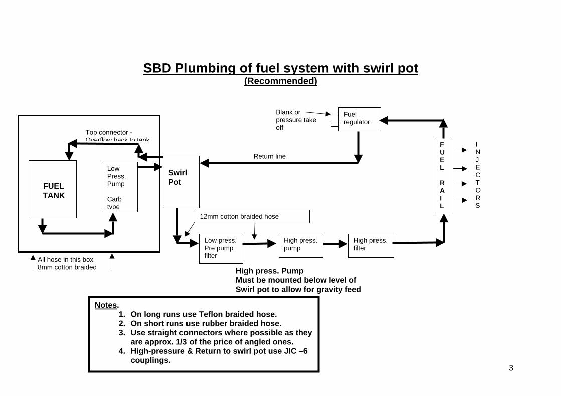
SBD Plumbing of fuel system with swirl pot (Recommended)
All hose in this box 8mm cotton braided High press. Pump
Must be mounted below level of Swirl pot to allow for gravity feed
Notes. 1. On long runs use Teflon braided hose. 2. On short runs use rubber braided hose. 3. Use straight connectors where possible as they
are approx. 1/3 of the price of angled ones. 4. High-pressure & Return to swirl pot use JIC –6
couplings.
FUEL TANK
Low Press. Pump Carb type
Top connector - Overflow back to tank
Swirl Pot
Low press.Pre pump filter
High press. pump
12mm cotton braided hose
High press.filter
FUEL
RAIL
Blank or pressure take off
Return line
Fuel regulator
I NJECTORS
3
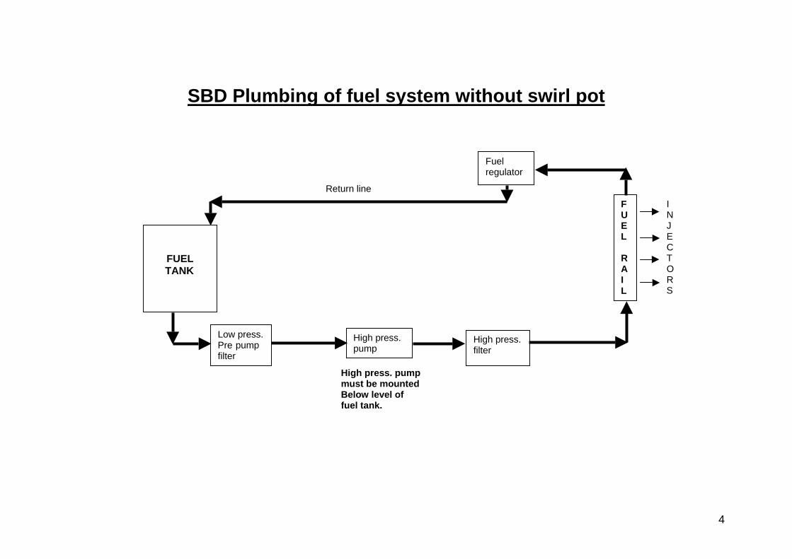
SBD Plumbing of fuel system without swirl pot
FUEL TANK
Low press.Pre pump filter
High press.pump
High press.filter
FUEL
RAIL
Fuel regulator
Return lineI NJECTORS
High press. pump must be mounted Below level of fuel tank.
4
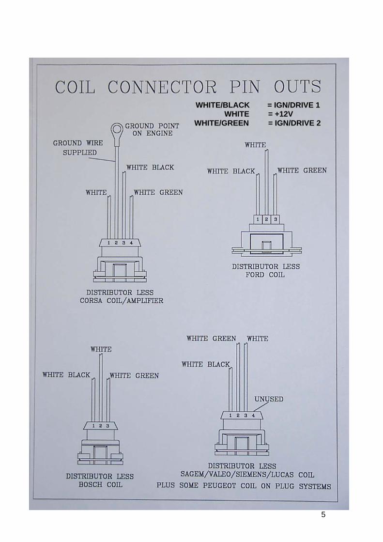
WHITE/BLACK = IGN/DRIVE 1 WHITE = +12V WHITE/GREEN = IGN/DRIVE 2
5
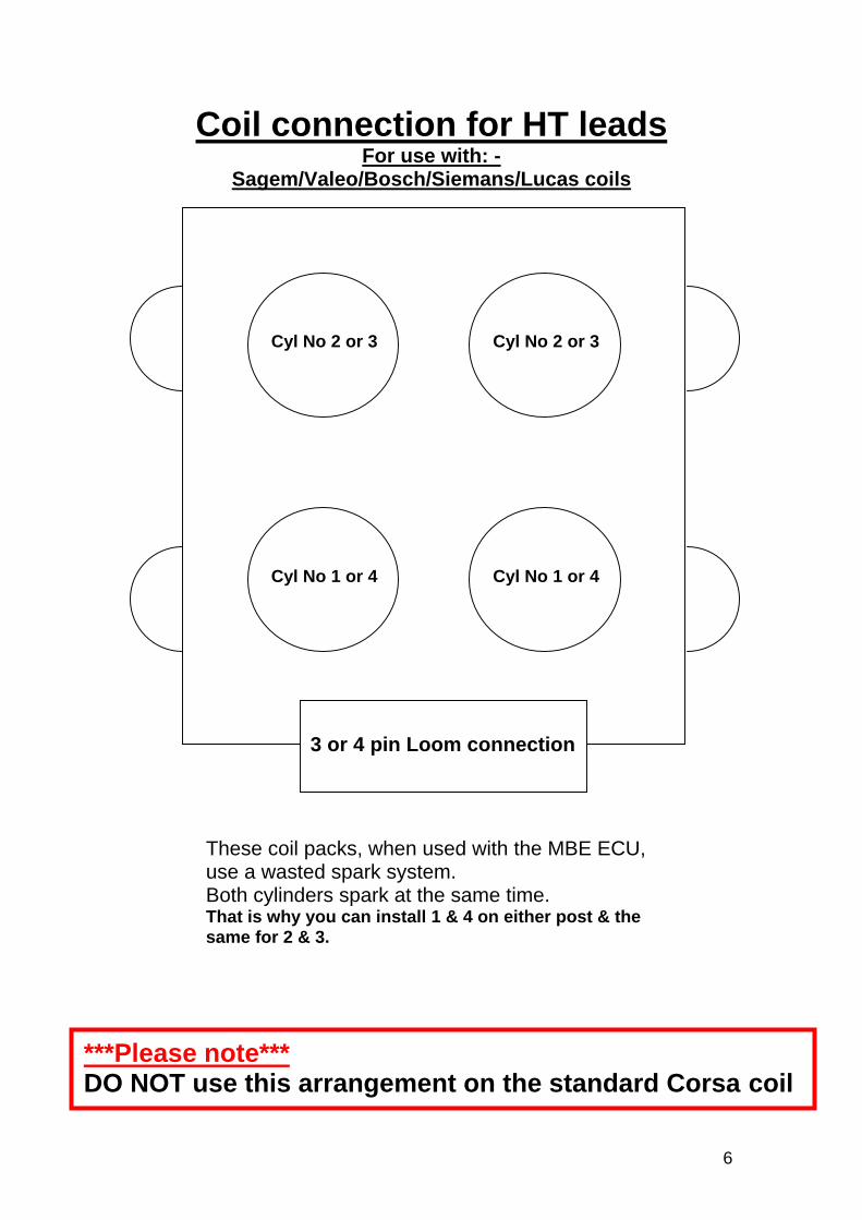
Coil connection for HT leads For use with: -
Sagem/Valeo/Bosch/Siemans/Lucas coils
3 or 4 pin Loom connection
Cyl No 2 or 3Cyl No 2 or 3
Cyl No 1 or 4 Cyl No 1 or 4
These coil packs, when used with the MBE ECU, use a wasted spark system. Both cylinders spark at the same time. That is why you can install 1 & 4 on either post & the same for 2 & 3.
***Please note*** DO NOT use this arrangement on the standard Corsa coil
6
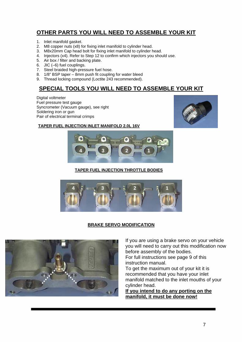
OTHER PARTS YOU WILL NEED TO ASSEMBLE YOUR KIT 1. Inlet manifold gasket. 2. M8 copper nuts (x8) for fixing inlet manifold to cylinder head. 3. M8x20mm Cap head bolt for fixing inlet manifold to cylinder head. 4. Injectors (x4). Refer to Step 12 to confirm which injectors you should use. 5. Air box / filter and backing plate. 6. JIC (–6) fuel couplings. 7. Steel braided high-pressure fuel hose. 8. 1/8” BSP taper – 8mm push fit coupling for water bleed 9. Thread locking compound (Loctite 243 recommended).
SPECIAL TOOLS YOU WILL NEED TO ASSEMBLE YOUR KIT
Digital voltmeter Fuel pressure test gauge Syncrometer (Vacuum gauge), see right Soldering iron or gun Pair of electrical terminal crimps TAPER FUEL INJECTION INLET MANIFOLD 2.0L 16V
4 3 2 1
TAPER FUEL INJECTION THROTTLE BODIES
1 2
124 34 3
BRAKE SERVO MODIFICATION
If you are using a brake servo on your vehicle you will need to carry out this modification now before assembly of the bodies. For full instructions see page 9 of this instruction manual. To get the maximum out of your kit it is recommended that you have your inlet manifold matched to the inlet mouths of your cylinder head. If you intend to do any porting on the manifold, it must be done now!
7
8
4
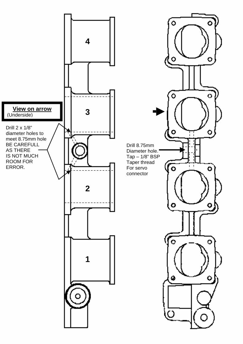
Drill 8.75mm Diameter hole. Tap – 1/8” BSP Taper thread For servo connector
Drill 2 x 1/8” diameter holes to meet 8.75mm hole BE CAREFULL AS THERE IS NOT MUCH ROOM FOR ERROR.
View on arrow (Underside)
2
3
1
Assembly procedure
9
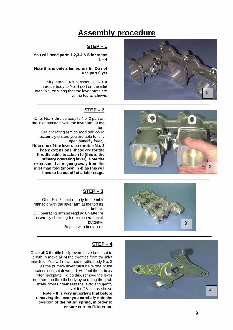
STEP – 1
You will need parts 1,2,3,4 & 5 for steps1 – 4
Note this is only a temporary fit. Do notuse part 6 yet
Using parts 3,4 & 5, assemble No. 4throttle body to No. 4 port on the inlet
manifold, ensuring that the lever arms areat the top as shown.
STEP – 2
Offer No. 3 throttle body to No. 3 port onthe inlet manifold with the lever arm at the
top.Cut operating arm as reqd and on re
assembly ensure you are able to fullyopen butterfly freely.
Note one of the levers on throttle No. 3has 2 extensions; these are for the
throttle cable to attach to (this is theprimary operating lever). Note the
extension that is going away from theinlet manifold (shown in 4) as this will
have to be cut off at a later stage.
STEP – 3
Offer No. 2 throttle body to the inletmanifold with the lever arm at the top as
before.Cut operating arm as reqd again after reassembly checking for free operation of
butterfly.Repeat with body no.1
4
STEP – 4
Once all 3 throttle body levers have been cut tolength, remove all of the throttles from the inletmanifold. You will now need throttle body No. 3
as the primary lever must have one of theextensions cut down or it will foul the airbox /filter backplate. To do this, remove the lever
arm from the throttle body by undoing the grubscrew from underneath the lever and gently
lever it off & cut as shownNote – It is very important that before
removing the lever you carefully note theposition of the return spring, in order to
ensure correct fit later on.
3
2
1
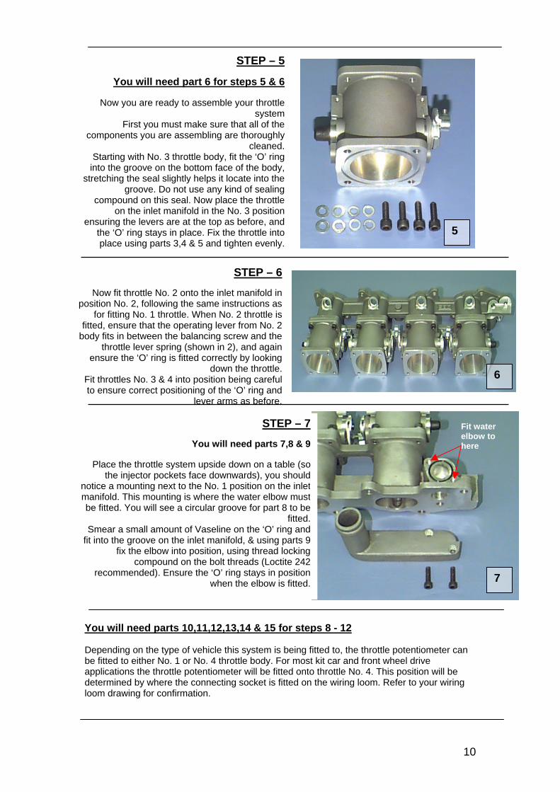
STEP – 5
You will need part 6 for steps 5 & 6
Now you are ready to assemble your throttlesystem
First you must make sure that all of thecomponents you are assembling are thoroughly
cleaned.Starting with No. 3 throttle body, fit the ‘O’ ring
into the groove on the bottom face of the body,stretching the seal slightly helps it locate into the
groove. Do not use any kind of sealingcompound on this seal. Now place the throttle
on the inlet manifold in the No. 3 positionensuring the levers are at the top as before, and
the ‘O’ ring stays in place. Fix the throttle intoplace using parts 3,4 & 5 and tighten evenly.
5
6
7
STEP – 7
You will need parts 7,8 & 9
Place the throttle system upside down on a table (sothe injector pockets face downwards), you should
notice a mounting next to the No. 1 position on the inletmanifold. This mounting is where the water elbow mustbe fitted. You will see a circular groove for part 8 to be
fitted.Smear a small amount of Vaseline on the ‘O’ ring and
fit into the groove on the inlet manifold, & using parts 9fix the elbow into position, using thread locking
compound on the bolt threads (Loctite 242recommended). Ensure the ‘O’ ring stays in position
when the elbow is fitted.
Fit water elbow to here
STEP – 6
Now fit throttle No. 2 onto the inlet manifold inposition No. 2, following the same instructions as
for fitting No. 1 throttle. When No. 2 throttle isfitted, ensure that the operating lever from No. 2
body fits in between the balancing screw and thethrottle lever spring (shown in 2), and again
ensure the ‘O’ ring is fitted correctly by lookingdown the throttle.
Fit throttles No. 3 & 4 into position being carefulto ensure correct positioning of the ‘O’ ring and
lever arms as before.
You will need parts 10,11,12,13,14 & 15 for steps 8 - 12 Depending on the type of vehicle this system is being fitted to, the throttle potentiometer can be fitted to either No. 1 or No. 4 throttle body. For most kit car and front wheel drive applications the throttle potentiometer will be fitted onto throttle No. 4. This position will be determined by where the connecting socket is fitted on the wiring loom. Refer to your wiring loom drawing for confirmation.
1 10
3 2
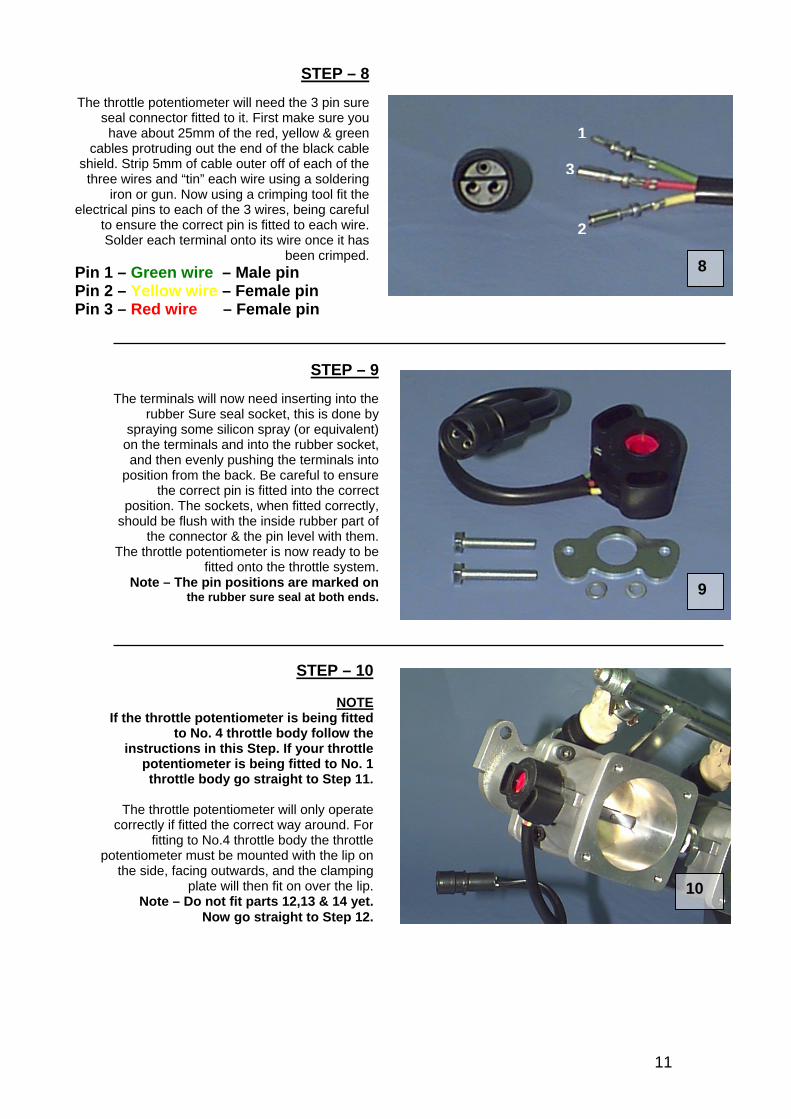
STEP – 8
The throttle potentiometer will need the 3 pin sureseal connector fitted to it. First make sure youhave about 25mm of the red, yellow & green
cables protruding out the end of the black cableshield. Strip 5mm of cable outer off of each of the
three wires and “tin” each wire using a solderingiron or gun. Now using a crimping tool fit the
electrical pins to each of the 3 wires, being carefulto ensure the correct pin is fitted to each wire.Solder each terminal onto its wire once it has
been crimped.Pin 1 – Green wire – Male pin Pin 2 – Yellow wire – Female pin Pin 3 – Red wire – Female pin
1
3
2
8
STEP – 9
The terminals will now need inserting into therubber Sure seal socket, this is done by
spraying some silicon spray (or equivalent)on the terminals and into the rubber socket,and then evenly pushing the terminals into
position from the back. Be careful to ensurethe correct pin is fitted into the correct
position. The sockets, when fitted correctly,should be flush with the inside rubber part of
the connector & the pin level with them.The throttle potentiometer is now ready to be
fitted onto the throttle system.Note – The pin positions are marked on
the rubber sure seal at both ends. 9
STEP – 10
NOTEIf the throttle potentiometer is being fitted
to No. 4 throttle body follow theinstructions in this Step. If your throttle
potentiometer is being fitted to No. 1throttle body go straight to Step 11.
The throttle potentiometer will only operatecorrectly if fitted the correct way around. For
fitting to No.4 throttle body the throttlepotentiometer must be mounted with the lip on
the side, facing outwards, and the clampingplate will then fit on over the lip.
Note – Do not fit parts 12,13 & 14 yet.Now go straight to Step 12.
10
11
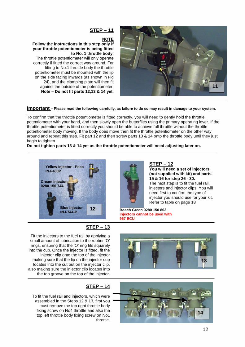
STEP – 11
NOTEFollow the instructions in this step only ifyour throttle potentiometer is being fitted
to No. 1 throttle body.The throttle potentiometer will only operate
correctly if fitted the correct way around. Forfitting to No.1 throttle body the throttle
potentiometer must be mounted with the lipon the side facing inwards (as shown in Fig
24), and the clamping plate will then fitagainst the outside of the potentiometer.Note – Do not fit parts 12,13 & 14 yet.
11
Important – Please read the following carefully, as failure to do so may result in damage to your system. To confirm that the throttle potentiometer is fitted correctly, you will need to gently hold the throttle potentiometer with your hand, and then slowly open the butterflies using the primary operating lever. If the throttle potentiometer is fitted correctly you should be able to achieve full throttle without the throttle potentiometer body moving. If the body does move then fit the throttle potentiometer on the other way around and repeat this step. Fit part 12 and then screw parts 13 & 14 onto the throttle body until they just begin to tighten. Do not tighten parts 13 & 14 yet as the throttle potentiometer will need adjusting later on.
Bosch Green 0280 150 803 injectors cannot be used with 967 ECU
STEP – 12 You will need a set of injectors (not supplied with kit) and parts 15 & 16 for step 26 - 30. The next step is to fit the fuel rail, injectors and injector clips. You will need first to confirm the type of injector you should use for your kit. Refer to table on page 18
12
Cream Injector 0280 150 744
Blue Injector INJ-744-P
Yellow Injector - Peco INJ-480P
STEP – 13
Fit the injectors to the fuel rail by applying asmall amount of lubrication to the rubber ‘O’rings, ensuring that the ‘O’ ring fits squarely
into the cup. Once the injector is fitted, fit theinjector clip onto the top of the injector
making sure that the lip on the injector cuplocates into the cut out on the injector clip,
also making sure the injector clip locates intothe top groove on the top of the injector.
13
14
STEP – 14
To fit the fuel rail and injectors, which wereassembled in the Steps 12 & 13, first you
must remove the top right throttle bodyfixing screw on No4 throttle and also thetop left throttle body fixing screw on No1
throttle.
12
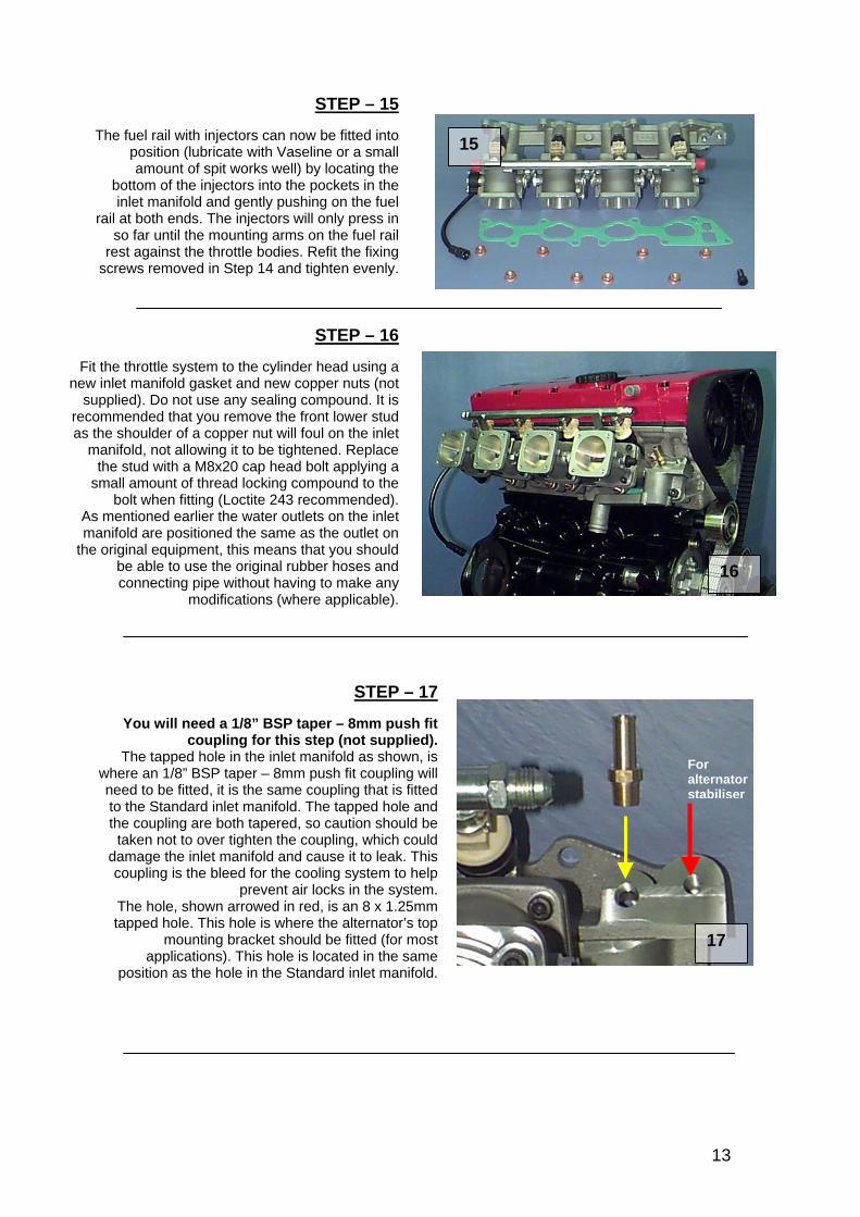
STEP – 15
The fuel rail with injectors can now be fitted intoposition (lubricate with Vaseline or a smallamount of spit works well) by locating the
bottom of the injectors into the pockets in theinlet manifold and gently pushing on the fuel
rail at both ends. The injectors will only press inso far until the mounting arms on the fuel rail
rest against the throttle bodies. Refit the fixingscrews removed in Step 14 and tighten evenly.
15
STEP – 16
Fit the throttle system to the cylinder head using anew inlet manifold gasket and new copper nuts (not
supplied). Do not use any sealing compound. It isrecommended that you remove the front lower studas the shoulder of a copper nut will foul on the inlet
manifold, not allowing it to be tightened. Replacethe stud with a M8x20 cap head bolt applying a
small amount of thread locking compound to thebolt when fitting (Loctite 243 recommended).
As mentioned earlier the water outlets on the inletmanifold are positioned the same as the outlet on
the original equipment, this means that you shouldbe able to use the original rubber hoses andconnecting pipe without having to make any
modifications (where applicable).
16
STEP – 17
You will need a 1/8” BSP taper – 8mm push fitcoupling for this step (not supplied).
The tapped hole in the inlet manifold as shown, iswhere an 1/8” BSP taper – 8mm push fit coupling willneed to be fitted, it is the same coupling that is fittedto the Standard inlet manifold. The tapped hole andthe coupling are both tapered, so caution should be
taken not to over tighten the coupling, which coulddamage the inlet manifold and cause it to leak. Thiscoupling is the bleed for the cooling system to help
prevent air locks in the system.The hole, shown arrowed in red, is an 8 x 1.25mmtapped hole. This hole is where the alternator’s top
mounting bracket should be fitted (for mostapplications). This hole is located in the same
position as the hole in the Standard inlet manifold.
17
For alternator stabiliser
13
18
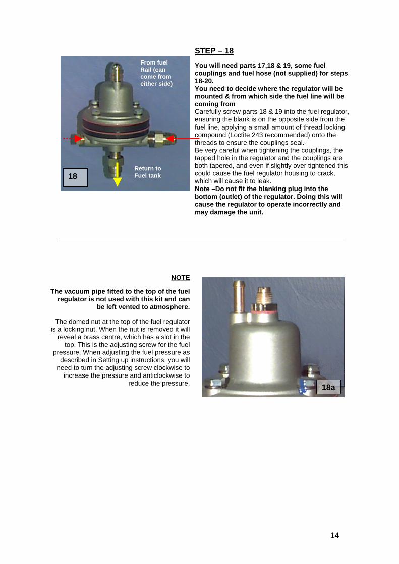
From fuel Rail (can come from either side)
Return to Fuel tank
STEP – 18 You will need parts 17,18 & 19, some fuel couplings and fuel hose (not supplied) for steps 18-20. You need to decide where the regulator will be mounted & from which side the fuel line will be coming from Carefully screw parts 18 & 19 into the fuel regulator, ensuring the blank is on the opposite side from the fuel line, applying a small amount of thread locking compound (Loctite 243 recommended) onto the threads to ensure the couplings seal. Be very careful when tightening the couplings, the tapped hole in the regulator and the couplings are both tapered, and even if slightly over tightened this could cause the fuel regulator housing to crack, which will cause it to leak. Note –Do not fit the blanking plug into the bottom (outlet) of the regulator. Doing this will cause the regulator to operate incorrectly and may damage the unit.
NOTE
The vacuum pipe fitted to the top of the fuelregulator is not used with this kit and can
be left vented to atmosphere.
The domed nut at the top of the fuel regulatoris a locking nut. When the nut is removed it will
reveal a brass centre, which has a slot in thetop. This is the adjusting screw for the fuel
pressure. When adjusting the fuel pressure asdescribed in Setting up instructions, you will
need to turn the adjusting screw clockwise toincrease the pressure and anticlockwise to
reduce the pressure. 18a
14
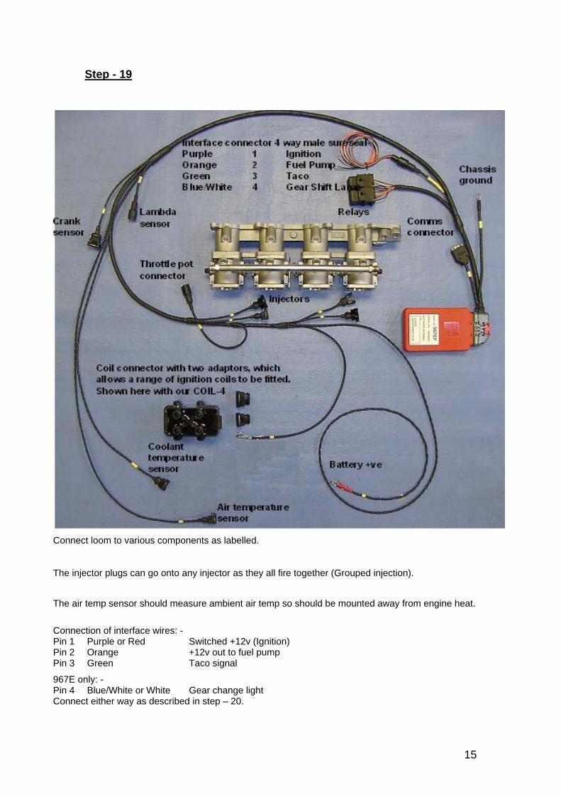
Step - 19
Connect loom to various components as labelled. The injector plugs can go onto any injector as they all fire together (Grouped injection). The air temp sensor should measure ambient air temp so should be mounted away from engine heat.
Connection of interface wires: - Pin 1 Purple or Red Switched +12v (Ignition) Pin 2 Orange +12v out to fuel pump Pin 3 Green Taco signal
967E only: - Pin 4 Blue/White or White Gear change light Connect either way as described in step – 20.
15
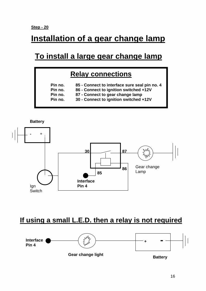
Step - 20
Installation of a gear change lamp
Relay connections Pin no. 85 - Connect to interface sure seal pin no. 4 Pin no. 86 - Connect to ignition switched +12V Pin no. 87 - Connect to gear change lamp Pin no. 30 - Connect to ignition switched +12V
To install a large gear change lamp
Battery
Ign Switch
Interface Pin 4
30 87
8586
- +
Gear change Lamp
If using a small L.E.D. then a relay is not required
+
Gear change light Battery
Interface Pin 4
16
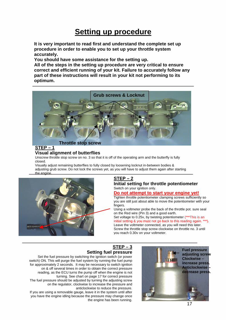
Setting up procedure It is very important to read first and understand the complete set up procedure in order to enable you to set up your throttle system accurately. You should have some assistance for the setting up. All of the steps in the setting up procedure are very critical to ensure correct and efficient running of your kit. Failure to accurately follow any part of these instructions will result in your kit not performing to its optimum.
STEP – 2 Initial setting for throttle potentiometer Switch on your ignition only. Do not attempt to start your engine yet! Tighten throttle potentiometer clamping screws sufficiently so you are still just about able to move the potentiometer with your fingers. Using a voltmeter probe the back of the throttle pot. sure seal on the Red wire (Pin 3) and a good earth. Set voltage to 0.25v, by twisting potentiometer (***This is an initial setting & you must not go back to this reading again. ***). Leave the voltmeter connected, as you will need this later. Screw the throttle stop screw clockwise on throttle no. 3 until you reach 0.30v on your voltmeter.
Grub screws & Locknut
STEP – 1 Visual alignment of butterflies Unscrew throttle stop screw on no. 3 so that it is off of the operating arm and the butterfly is fully closed. Visually adjust remaining butterflies to fully closed by loosening locknut in-between bodies & adjusting grub screw. Do not lock the screws yet, as you will have to adjust them again after starting the engine.
Throttle stop screw
17
STEP – 3Setting fuel pressure
Set the fuel pressure by switching the ignition switch (or powerswitch) ON. This will purge the fuel system by running the fuel pumpfor approximately 2 seconds. It may be necessary to switch ignition
on & off several times in order to obtain the correct pressurereading, as the ECU turns the pump off when the engine is not
turning. See chart on page 17 for correct pressureThe fuel pressure should be adjusted by turning the adjusting screw
on the regulator, clockwise to increase the pressure andanticlockwise to reduce the pressure.
If you are using a removable gauge, leave it in the system until afteryou have the engine idling because the pressure may change once
the engine has been running.
Fuel pressure adjusting screw Clockwise – increase press. Anticlockwise – decrease press.
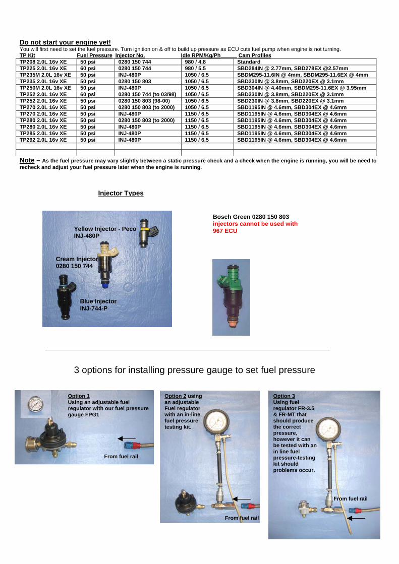
Do not start your engine yet! You will first need to set the fuel pressure. Turn ignition on & off to build up pressure as ECU cuts fuel pump when engine is not turning. TP Kit Fuel Pressure Injector No. Idle RPM/Kg/Ph Cam Profiles TP208 2.0L 16v XE 50 psi 0280 150 744 980 / 4.8 Standard TP225 2.0L 16v XE 60 psi 0280 150 744 980 / 5.5 SBD284IN @ 2.77mm, SBD278EX @2.57mm TP235M 2.0L 16v XE 50 psi INJ-480P 1050 / 6.5 SBDM295-11.6IN @ 4mm, SBDM295-11.6EX @ 4mm TP235 2.0L 16v XE 50 psi 0280 150 803 1050 / 6.5 SBD230IN @ 3.8mm, SBD220EX @ 3.1mm TP250M 2.0L 16v XE 50 psi INJ-480P 1050 / 6.5 SBD304IN @ 4.40mm, SBDM295-11.6EX @ 3.95mm TP252 2.0L 16v XE 60 psi 0280 150 744 (to 03/98) 1050 / 6.5 SBD230IN @ 3.8mm, SBD220EX @ 3.1mm TP252 2.0L 16v XE 50 psi 0280 150 803 (98-00) 1050 / 6.5 SBD230IN @ 3.8mm, SBD220EX @ 3.1mm TP270 2.0L 16v XE 50 psi 0280 150 803 (to 2000) 1050 / 6.5 SBD1195IN @ 4.6mm, SBD304EX @ 4.6mm TP270 2.0L 16v XE 50 psi INJ-480P 1150 / 6.5 SBD1195IN @ 4.6mm, SBD304EX @ 4.6mm TP280 2.0L 16v XE 50 psi 0280 150 803 (to 2000) 1150 / 6.5 SBD1195IN @ 4.6mm, SBD304EX @ 4.6mm TP280 2.0L 16v XE 50 psi INJ-480P 1150 / 6.5 SBD1195IN @ 4.6mm. SBD304EX @ 4.6mm TP285 2.0L 16v XE 50 psi INJ-480P 1150 / 6.5 SBD1195IN @ 4.6mm, SBD304EX @ 4.6mm TP292 2.0L 16v XE 50 psi INJ-480P 1150 / 6.5 SBD1195IN @ 4.6mm, SBD304EX @ 4.6mm Note – As the fuel pressure may vary slightly between a static pressure check and a check when the engine is running, you will be need to recheck and adjust your fuel pressure later when the engine is running.
Injector Types
18
Bosch Green 0280 150 803 injectors cannot be used with 967 ECU
Option 1 Using an adjustable fuel regulator with our fuel pressure gauge FPG1
From fuel rail
Option 2 using an adjustable Fuel regulator with an in-line fuel pressure testing kit.
Option 3 Using fuel regulator FR-3.5 & FR-MT that should produce the correct pressure, however it can be tested with an in line fuel pressure-testing kit should problems occur.
From fuel rail
From fuel rail
3 options for installing pressure gauge to set fuel pressure
Yellow Injector - Peco INJ-480P
Blue Injector INJ-744-P
Cream Injector 0280 150 744
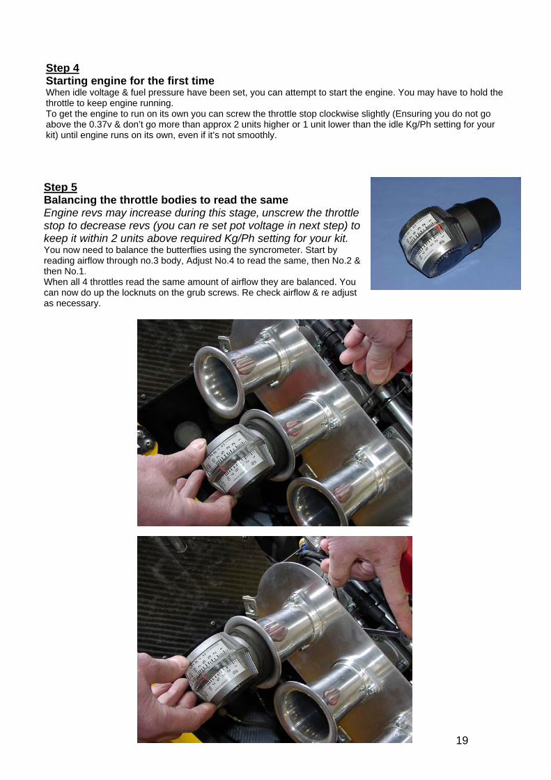
Step 4 Starting engine for the first time When idle voltage & fuel pressure have been set, you can attempt to start the engine. You may have to hold the throttle to keep engine running. To get the engine to run on its own you can screw the throttle stop clockwise slightly (Ensuring you do not go above the 0.37v & don’t go more than approx 2 units higher or 1 unit lower than the idle Kg/Ph setting for your kit) until engine runs on its own, even if it’s not smoothly.
Step 5 Balancing the throttle bodies to read the same Engine revs may increase during this stage, unscrew the throttle stop to decrease revs (you can re set pot voltage in next step) to keep it within 2 units above required Kg/Ph setting for your kit. You now need to balance the butterflies using the syncrometer. Start by reading airflow through no.3 body, Adjust No.4 to read the same, then No.2 & then No.1. When all 4 throttles read the same amount of airflow they are balanced. You can now do up the locknuts on the grub screws. Re check airflow & re adjust as necessary.
19
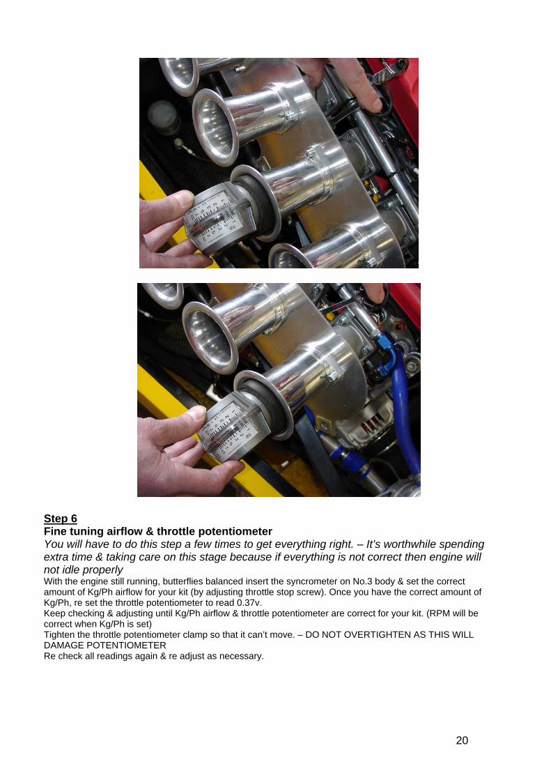
Step 6 Fine tuning airflow & throttle potentiometer You will have to do this step a few times to get everything right. – It’s worthwhile spending extra time & taking care on this stage because if everything is not correct then engine will not idle properly With the engine still running, butterflies balanced insert the syncrometer on No.3 body & set the correct amount of Kg/Ph airflow for your kit (by adjusting throttle stop screw). Once you have the correct amount of Kg/Ph, re set the throttle potentiometer to read 0.37v. Keep checking & adjusting until Kg/Ph airflow & throttle potentiometer are correct for your kit. (RPM will be correct when Kg/Ph is set) Tighten the throttle potentiometer clamp so that it can’t move. – DO NOT OVERTIGHTEN AS THIS WILL DAMAGE POTENTIOMETER Re check all readings again & re adjust as necessary.
20
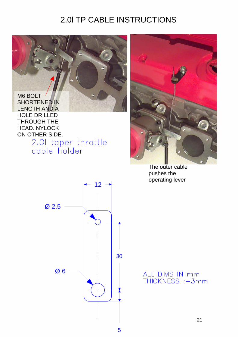
2.0l TP CABLE INSTRUCTIONS
M6 BOLT SHORTENED IN LENGTH AND A HOLE DRILLED THROUGH THE HEAD. NYLOCK ON OTHER SIDE.
5
30
Ø 6
12
Ø 2.5
The outer cable pushes the operating lever
21