sbe1 recording, tracking + ip conversion module user … · sbe1 recording, tracking + ip...
TRANSCRIPT

SPI CORP M2D TRIP EOIR GIMBAL SYSTEM
SBE1 Recording, Tracking + IP Conversion
Module User Manual
! Ver 2.0
This document is the property of SPI CORP www.x20.org

TRIP Manual Ver : 1.8 www.x20.org
Compilation and Publication Notice
This manual covers the latest product descriptions and specifications.
The contents of this manual and the specifications of this product are subject to change without notice.
SPI reserves the right to make changes without notice in the specifications and materials contained herein and shall not be responsible for any damages (including consequential) caused by reliance on the materials presented, including but not limited to typographical and other errors relating to the publication.
For Further information please contact
SPI CORP
Table of Content
- Page ! of ! – 2 41- SPI Proprietary and Confidential Information -

TRIP Manual Ver : 1.8 www.x20.org
1. Introduction 4
2. Architecture 5
3. Physical connectivity 6 .......................................................................3.1.WireHarness 7
4. Functionality 8
5. IP Setting 10
6. SBE1 Board Setting 11 .......................................................................
7. SBE1 Board Firmware Update 23 ......................................................
8. SBE1 Video Preview 24 ......................................................................
9. SBE1 Video Preview With VLC 31 ....................................................
10.KLV Metadata 34 ................................................................................
Appendix A : Version Control 40.............................................................
- Page ! of ! – 3 41- SPI Proprietary and Confidential Information -

TRIP Manual Ver : 1.8 www.x20.org
1. Introduction
The document includes the user manual of SPI’s Recording, Tracking and IP conversion (SBE1) OEM board. Note: The SBE1 board supports M2D protocols.
- Page ! of ! – 4 41- SPI Proprietary and Confidential Information -

TRIP Manual Ver : 1.8 www.x20.org
2. Architecture
The architecture of the SBE1 Module is depicted in the following:
!
- Page ! of ! – 5 41- SPI Proprietary and Confidential Information -

TRIP Manual Ver : 1.8 www.x20.org
3. Physical connectivity
The SBE1 board includes the following connectors:
Designation
Connectto Type PinDescription
J1 M2Dcamera MolexPicoBladeTM10pin
Pin Function1 CameraPowerIN(12-32V)*maxvoltagedependsoncamera2 GND3 RS232RX(TRIPOut,CameraIn)4 RS232TX(TRIPIn,Cameraout)5 GND6 NC7 NC8 NC9 AnalogVideoIn10 AnalogVideoReturn(VIDEO_GND)
J2 HostSerialPort,AnalogDisplay,Power
MolexPicoBladeTM10pin
Pin Function1 ExternalPowerIN(12-32V)*maxvoltagedependsoncamera2 GND3 RS232RX(HostOut,TRIPIn),Dualfunction(ExternalRS232ControlorGPS)4 RS232TX(HostIn,TRIPout)5 GND6 DBG_RX (for factory use only, leaveunconnected)7 DBG_TX (for factory use only, leaveunconnected)8 DBG_GND9 AnalogVideoOut10 AnalogVideoReturn(VIDEO_GND)
J3 Input(HDMI) MicroHDMI StandardMicroHDMIConnector
J4 DigitalDisplay(HDMI)
MicroHDMI StandardMicroHDMIConnector
- Page ! of ! – 6 41- SPI Proprietary and Confidential Information -

TRIP Manual Ver : 1.8 www.x20.org
3.1. Wire Harness
J5 HostUSBPort M o l e xPicoBladeTM4pin
Pin Function1 USB_HOST_VCC(+5V)SuppliedfromTRIPtoTarget2 USB_HOST_DATA+(DP)3 USB_HOST_DATA-(DM)4 GND
J6 Host EthernetPort
MolexPicoBladeTM5pin
Pin Function1 ETH_TX+2 ETH_TX-3 ETH_RX+4 ETH_RX-5 ETH_GND(optional)
J7 Memorycard MicroSDslot
StandardMicroSDslot
P.N Connector Description
2042 J1 Connecting SBE1 to Camera
The wire harness includes two Molex 51021-1000 connectors and 50cm [19.5”] long ultra flexible wires.
2042 J2 Connecting SBE1 to PIB
The wire harness includes two Molex 51021-1000 connectors and 50cm [19.5”] long ultra flexible wires.
2081 J5 Connecting SBE1 to USB Host
The wire harness includes a Molex 51021-0400 connector and USB Receptacle Connector (Female) and 50cm [19.5”] long ultra flexible wires.
- Page ! of ! – 7 41- SPI Proprietary and Confidential Information -

TRIP Manual Ver : 1.8 www.x20.org
J3 cable can be sourced from any video store
4. Functionality
The SBE1 is available in two different flavors: SD – Standard Definition HD – High Definition Common functions that are supported by both flavors:
• IP Streaming of captured video using the following format: Mpeg2Ts over RTP with H264 compression.
• Receiving protocol commands from the user through RS232 (J2 connector) or through IP over Ethernet (J6 connector)
• Sending protocol commands to the camera through J1 connector
• Recording the video on the SD card upon protocol command. Adding GPS meta data to stored frames.
• Tracking object in the video upon protocol command.
• Notify loss of object tracking through protocol.
• Detecting motion in the video upon protocol command.
• Notify motion detection through protocol.
2082 J6 Connecting SBE1 to Ethernet
The wire harness includes a Molex 51021-0500 connector and RJ-45 Jack (Female) and 50cm [19.5”] long ultra flexible wires.
- Page ! of ! – 8 41- SPI Proprietary and Confidential Information -

TRIP Manual Ver : 1.8 www.x20.org
The SBE1-SD board performs the following additional functions:
• Autodetection of PAL/NTSC video from the camera through J1 connector
• Outputting digital video on J4 HDMI connector, When the input video is PAL than the HDMI output transmits: 576p@50Hz format. When the input video is NTSC than the HDMI output transmits: 480p@60Hz format.
The SBE1-HD board performs the following additional functions:
• Capture digital video from the camera through J3 HDMI connector, the captured format is 720p@60Hz
• Outputting digital video on J3 HDMI connector, The HDMI output transmits: 720p@60Hz.
- Page ! of ! – 9 41- SPI Proprietary and Confidential Information -

TRIP Manual Ver : 1.8 www.x20.org
5. IP Setting
The SBE1 board default IP address is: 192.168.0.201 with the following subnet mask: 255.255.255.0
In cases that there is no possible way to update the host IP address due to lack of administrative rights the SBE1 Discovery Tool offers a way to find units and update their IP settings from any network transcending subnet settings. Open the discovery tool:
In order to display all the units that are available on network Press on the Find Boards button on the Discovery Units:
- Page ! of ! – 10 41- SPI Proprietary and Confidential Information -

TRIP Manual Ver : 1.8 www.x20.org
Update the configuration of the unit that you wish to update and make sure to select yes in the set column. It is necessary to highlight the V unit required to change IP.
Press on the update button in order to configure the selected IP
6. SBE1 Board Setting
In order to configure several parameters of the SBE1 board make sure that the controlling PC station is configured with the same class & subnet mask as the SBE1 board.
Access the SBE1 website with any standard web browser, when prompted for a user & password use:
User: admin Password: microcam
- Page ! of ! – 11 41- SPI Proprietary and Confidential Information -

TRIP Manual Ver : 1.8 www.x20.org
The Network tab allows the configuration of network related parameters:
• IP address
• Subnet mask
• Default gateway
• MTU – maximum transmission unit
The Channel tab allows the configuration of the video and encoding related parameters:
• Input Format – defines which video signal will be processed by the platform: SD – Standard Definition:
TRIP will use the analog video signal from J1 connector, this mode supports auto detection of PAL & NTSC.
HD – High Definition:SBE1 will use the digital video signal from J3 HDMI connector, this mode supports 720p only.
• Destination IP Address – video will be transmitted to this IP address, both unicast and multicast addresses are supported
- Page ! of ! – 12 41- SPI Proprietary and Confidential Information -
TRIP Manual Ver : 1.8 www.x20.org
• Destination IP Port – video will be transmitted to this Port
• Enable Bandwidth Limit – Enable/Disable Bandwidth limiting
• Bandwidth Limit – Bandwidth limit value in kbps, in affect only when bandwidth limit is enabled
• NTSC Field Order – When the captured input video standard is NTSC this parameter defines which field is captured first: Odd or Even.
• Encoding Mode:
o CBR – Constant BitRate: bit rate will never exceed this value even when the video quality decreases due to fast changes in the video
o ConstQ – Constant Quality: bit rate will be modified according to the video frames in order to keep the quality constant, with ConstQ the bitrate field is ignored
• Bitrate – bitrate in kbps to use, only relevant when encoding mode is set to CBR
• Quantization Value – defines the relation between the quality of the compressed stream and its size, a low value dictates more quality with larger compressed size where a high value dictates the opposite. The value range is: 0 – 51. If not sure it is highly recommended to leave this value at 25
• Algorithm – defines which algorithm will be used on the input video: Tracker or VMD
- Page ! of ! – 13 41- SPI Proprietary and Confidential Information -
TRIP Manual Ver : 1.8 www.x20.org
- Page ! of ! – 14 41- SPI Proprietary and Confidential Information -

TRIP Manual Ver : 1.8 www.x20.org
The Protocol tab allows the configuration of protocol related parameters:
• Protocol Type – defines which protocol will be processed by the SBE1 board:AutoDetect – Automatic detection of the protocol, In this mode the SBE1 detects the protocol that is arriving from the host and uses the same protocol to control the camera, The SBE1 is able to detect M2D protocols. will be able to process tracking & recording commands
• Protocol Medium – defines the physical layer that the protocol will use: Serial (RS232) or IP. When Serial is used the standard serial configuration of the protocol is in affect: 19200bps, 8 bit width, 1 stop bit, even parity When IP is used all other settings are in affect
• Remote IP – the IP of the host or controlling station
• Remote Port – the Port number of the host or controlling station
• Local Port – the Port number that SBE1 listens to for incoming host protocol messages.
** both Remote IP/Port and Local Port must match the settings that are configured at the SPI Camera Control software
- Page ! of ! – 15 41- SPI Proprietary and Confidential Information -

TRIP Manual Ver : 1.8 www.x20.org
The Tracker tab allows the configuration of tracker related parameters:
• Threshold – the threshold value defines at which level to lose/retrack targets. The value is between 0 – 100. A higher number will make the tracking process more sensitive to fast changes in the video and may cause the tracker to lose or retrack the target while a lower value will do the exact opposite. Typical range for most scenes is: 25 – 50 Its always best to start with the default value of 37.5 and see how the tracker copes with the scene, for example if its to sensitive than lower the value in decrements of 2.5 to 5 until the desired behavior is achieved.
On darker/shaded scenes a value of 25 – 30 will work better On lighter/brighter scenes a value of 40 – 50 will work better When unsure a value of 37.5 is recommended.
• Enable Relocking – when the relock option is enabled the tracker will attempt to relock the target after the Relock Time (parameter). The process of the relock will keep a record of the trajectory of the target and in case of target loss the tracker will keep moving in the same direction of the object and attempt to relock after the defined relock time assuming that the disturbance has passed during the relock time and the target maintained the same trajectory.
• Relock Time – defines the amount of time to wait between target loss and a relock attempt relock time is measured in milliseconds
- Page ! of ! – 16 41- SPI Proprietary and Confidential Information -

TRIP Manual Ver : 1.8 www.x20.org
• Graphics Color – defines what will be the color of the tracker graphics, black or white.
• Tracker Image – defines which icon will be used when the tracker is actively tracking a target.
• Crosshair Image – defines which icon will be used when the tracker has to display a crosshair image, for example when a user attempts to retrack to a new target this icon will be used for the crosshair.
- Page ! of ! – 17 41- SPI Proprietary and Confidential Information -
TRIP Manual Ver : 1.8 www.x20.org
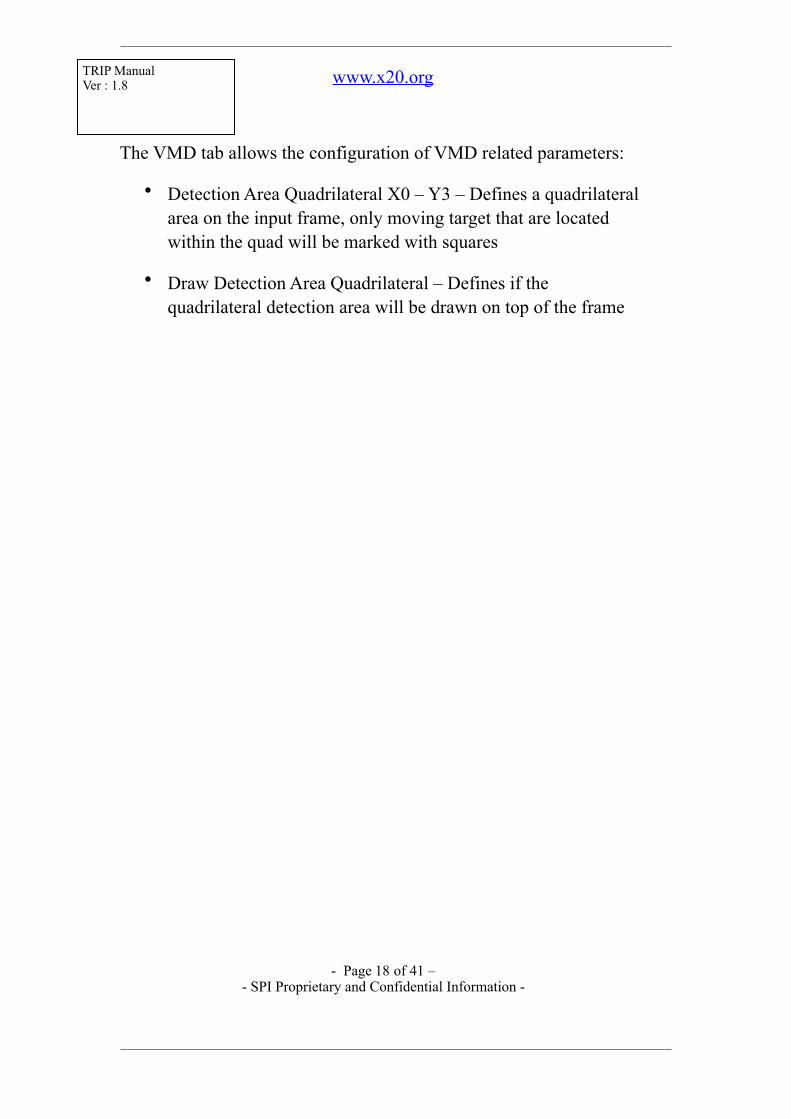
The VMD tab allows the configuration of VMD related parameters:
• Detection Area Quadrilateral X0 – Y3 – Defines a quadrilateral area on the input frame, only moving target that are located within the quad will be marked with squares
• Draw Detection Area Quadrilateral – Defines if the quadrilateral detection area will be drawn on top of the frame
- Page ! of ! – 18 41- SPI Proprietary and Confidential Information -

TRIP Manual Ver : 1.8 www.x20.org
The Camera tab allows the configuration of Camera related parameters:
• Gimbal Mounting Orientation – Defines how the camera is mount on the aircraft: Nose mountBelly mount
- Page ! of ! – 19 41- SPI Proprietary and Confidential Information -

TRIP Manual Ver : 1.8 www.x20.org
The System Setting tab allows the configuration of system related parameters:
• Reset to default configuration button – reverts the system setting to their factory defaults
- Page ! of ! – 20 41- SPI Proprietary and Confidential Information -

TRIP Manual Ver : 1.8 www.x20.org
The System Status tab shows various statuses of the device: • Video Standard – shows which video standard was detected by
the system: PAL, NTSC, 720p or No Input Video. This status may be used to verify that the analog/digital video from the camera is connected correctly to the SBE1 board
• Pressing on the REFRESH button will read the current statuses and display them on this tab
- Page ! of ! – 21 41- SPI Proprietary and Confidential Information -

TRIP Manual Ver : 1.8 www.x20.org
Pressing on the update button on the website will save the new setting and restart the SBE1 application using the new settings. In case there is an invalid value on the website the corresponding item of the erroneous field will be marked in red color:
Pressing on the reboot button will restart the SBE1 board
- Page ! of ! – 22 41- SPI Proprietary and Confidential Information -

TRIP Manual Ver : 1.8 www.x20.org
7. SBE1 Board Firmware Update
Steps to update the version of the SBE1. • Attach empty Micro SD card. • make sure that the SBE1 version is up to date. If not, update
to latest version. • Attach the “update Img.gz” file to the Micro SD card. • Turn off the SBE1 and insert micro SD card into trip. • Turn on the SBE1 and refresh internet page. • Re-check and see if there are any more updates to the SBE1
version.
- Page ! of ! – 23 41- SPI Proprietary and Confidential Information -

TRIP Manual Ver : 1.8 www.x20.org
8. SBE1 Video Preview
Use Spi Video Player to preview the video of the SBE1 board. The following table defines the what will be seen in the Video Player and in the SBE1 System Status Tab in various system states:
Condition
Analog Video
Connection
IP Link
Video Player Status
Indication
TRIP System Status Tab
Remarks
First Power
Up
Missing Missing
Detection Failed
No Video Input
Video Player window is filled with green color, System Status Tab shows No Input Video Image #1 – Video Player when in this stateImage #2 – Status Tab when in this state
Missing Present
Detection Ok
No Video Input
Video Player window is filled with blue color, System Status Tab shows No Input Video Image #3 – Video Player when in this stateImage #2 – Status Tab when in this state
- Page ! of ! – 24 41- SPI Proprietary and Confidential Information -

TRIP Manual Ver : 1.8 www.x20.org
Present Missing
Detection Failed
PAL or NTSC
Video Player window is filled with green color, System Status Tab shows PAL or NTSCImage #1 – Video Player when in this stateImage #4 – Status Tab when in this state
Present Present
Detection Ok
PAL or NTSC
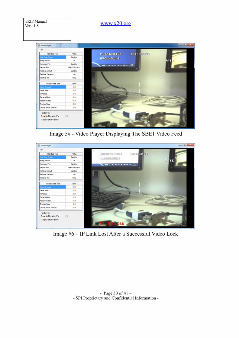
Video Player window is filled with the video feed, System Status Tab shows PAL or NTSCImage #5 – Video Player when in this stateImage #4 – Status Tab when in this state
After A Successf
ul Connecti
on
Missing Missing
IP Link Loss
No Video Input
Video Player window is filled with the video feed and an IP Link Loss indication is present on the bottom of the frame in red color System Status Tab shows No Video InputImage #6 – Video Player when in this stateImage #2 – Status Tab when in this state
- Page ! of ! – 25 41- SPI Proprietary and Confidential Information -

TRIP Manual Ver : 1.8 www.x20.org
Missing Present
Detection Ok
No Video Input
Video Player window is filled with blue color, System Status Tab shows No Input Video Image #3 – Video Player when in this stateImage #2 – Status Tab when in this state
Present Missing
IP Link Loss
PAL or NTSC
Video Player window is filled with the video feed and an IP Link Loss indication is present on the bottom of the frame in red color System Status Tab shows PAL or NTSCImage #6 – Video Player when in this stateImage #4 – Status Tab when in this state
Present Present
Detection Ok
PAL or NTSC
Video Player window is filled with the video feed, System Status Tab shows PAL or NTSCImage #5 – Video Player when in this stateImage #4 – Status Tab when in this state
- Page ! of ! – 26 41- SPI Proprietary and Confidential Information -

TRIP Manual Ver : 1.8 www.x20.org
- Page ! of ! – 27 41- SPI Proprietary and Confidential Information -

TRIP Manual Ver : 1.8 www.x20.org
! Image #1 – Detection Failed
! Image #3 – Analog Video is missing, IP link is Ok
- Page ! of ! – 28 41- SPI Proprietary and Confidential Information -

TRIP Manual Ver : 1.8 www.x20.org
- Page ! of ! – 29 41- SPI Proprietary and Confidential Information -
TRIP Manual Ver : 1.8 www.x20.org
! Image 5# - Video Player Displaying The SBE1 Video Feed
! Image #6 – IP Link Lost After a Successful Video Lock
- Page ! of ! – 30 41- SPI Proprietary and Confidential Information -

TRIP Manual Ver : 1.8 www.x20.org
9. SBE1 Video Preview With VLC
SPI video stream may also be previewed with VLC. Follow these steps in order to preview the video using VLC:
• Configure the SBE1 to transmit video to a unicast/multicast address, this may achieved be by following section 6 of this document
• Open the VLC player
!
• Select Media ! Open Network Stream…
Alternately you may press Ctrl + N to open the network stream window.
- Page ! of ! – 31 41- SPI Proprietary and Confidential Information -

TRIP Manual Ver : 1.8 www.x20.org
• The following window will appear
!
• In the network URL line please enter the following:
- For Unicast
Rtp://@:DestinationPort
- For MulticastRtp://@DestinationIP:DestinationPort
• Press the play button to start the video preview
- Page ! of ! – 32 41- SPI Proprietary and Confidential Information -

TRIP Manual Ver : 1.8 www.x20.org
!
• Example: Opening a unicast stream with VLC
- Configure the SBE1 to transmit to a unicast address:
- Note that the destination IP is configured to 192.168.0.4 which is a unicast address in our network The destination port is set to 11024
- Open the VLC player, Media ! Open Network StreamAnd enter the network configuration of the SBE1
!
- Page ! of ! – 33 41- SPI Proprietary and Confidential Information -

TRIP Manual Ver : 1.8 www.x20.org
- Press Play the preview the video
• Example: Opening a multicast stream with VLC
- Configure the TRIP to transmit to a multicast address (224.0.0.0 – 239.255.255.255):
- Note that the destination IP is configured to 225.1.2.3 which is a multicast address, the destination port is set to 11024
- Open the VLC player, Media ! Open Network StreamAnd enter the network configuration of the SBE1
!
- Press Play the preview the video
10.KLV Metadata
The video stream over IP includes KLV metadata in accordance with the following table:
TAG
LDS Name Remarks
- Page ! of ! – 34 41- SPI Proprietary and Confidential Information -

TRIP Manual Ver : 1.8 www.x20.org
1 Checksum Mandatory Tag
2 Unix Time Stamp Mandatory Tag
11 Image Source Sensor M2D
16 Sensor Horizontal Field of View
17 Sensor Vertica Field of View
18 Sensor Relative AzimuthAngle
Gimbal roll and pitch angles converted in accordance with gimbal mounting
19 Sensor Relative Elevation Angle
Gimbal roll and pitch angles converted in accordance with gimbal mounting
20 Sensor Relative Roll Angle Gimbal roll and pitch angles converted in accordance with gimbal mounting
101 Video Channel Proprietary Tag, defines which video channel is transmitted. The following table defines the available values for this tag:
Value Camera
0 Daylight Channel
1 Thermal Channel
102 Laser State Proprietary Tag, defines the laser state The following table defines the available values for this tag:
Value Laser State
0 Off
1 On
- Page ! of ! – 35 41- SPI Proprietary and Confidential Information -

TRIP Manual Ver : 1.8 www.x20.org
103 PIP State Proprietary Tag, defines if PIP is enabled The following table defines the available values for this tag:
Value PIP Enable
0 Disabled
1 Enabled
- Page ! of ! – 36 41- SPI Proprietary and Confidential Information -

TRIP Manual Ver : 1.8 www.x20.org
104 Camera Mode Proprietary Tag, defines which camera mode is currently active The following table defines the available values for this tag:
Value Camera Mode
0 Rate (auto drift on)
1 Point to coordinate
Hold coordinate 2
Pilot 3
Stow 4
Rate (auto drift off) 6
Dynamic drift compensation 7
Park 8
Gyro Calibration (static) & BIT 10
GRR 11
Reserved 1 for internal compass 12 calibration
Reserved 2 for internal compass 13 calibration
Enter EXT Mode 31
- Page ! of ! – 37 41- SPI Proprietary and Confidential Information -

TRIP Manual Ver : 1.8 www.x20.org
105 Recorder State Proprietary Tag, defines the state of the recorder The following table defines the available values for this tag:
Value Recorder State
0 Idle
1 Recording
106 Tracker State Proprietary Tag, defines the state of the tracker The following table defines the available values for this tag:
Value Tracker State
0 Idle
1 Tracking
Target Lost 2
107 Gimbal MountingOrientation
Proprietary Tag, defines the gimbal mounting orientation. Gimbal mounting orientation is configured through web access The following table defines the available values for this tag:
Value Orientation
0 Belly
1 Nose
- Page ! of ! – 38 41- SPI Proprietary and Confidential Information -

TRIP Manual Ver : 1.8 www.x20.org
- Page ! of ! – 39 41- SPI Proprietary and Confidential Information -

TRIP Manual Ver : 1.8 www.x20.org
Appendix A : Version Control
Version
Date Remarks
1.2 2 3 N o v 2016
Switching J1 and J2
1.3 2 4 N o v 2016
KLV
1.4 0 2 J a n 2017
VMD addition, Video Player / SBE1 System Status
1.5 1 9 J a n 2017
Revision of pictures and switches.
1.6 2 3 J a n 2017
Added section about SBE1 video preview using VLC
1.7 1 0 F e b 2017
Updated system architecture diagram Updated SBE1 IP Setting section (adding images of TRIP Discovery tool)
1.8 1 5 M a r 2017
Added SBE1 SD/HD flavors explanation Updated SBE1 website images Updated channel setting tab – New Input Format parameter Updated protocol setting tab – New protocol type & medium parameters
- Page ! of ! – 40 41- SPI Proprietary and Confidential Information -

TRIP Manual Ver : 1.8 www.x20.org
- Page ! of ! – 41 41- SPI Proprietary and Confidential Information -