sc instrumentation - honeywell... · sc instrumentation signal conditioning, self-calibrating...
TRANSCRIPT

Models SC1000 & SC2000
Model SC3004
SC Instrumentation
Signal Conditioning,Self-CalibratingDigital Indicators
Sensotec Sensors
Model SC2001
Sensing and Control
HoneywellSensotec Sensors2080 Arlingate LaneColumbus, Ohio 43228, USATelephone: (614)850-5000FAX: (614)850-1111Toll Free: 1-800-848-6564E-mail: [email protected]://www.honeywell.com/sensinghttp://www.sensotec.com
SC Series Instruction ManualModels SC1000, SC2000, SC2001 and SC3004
Document Number: 008-0608-00Rev. C: February, 2005
WARNINGThe operator of this instrument is advised that if the equipment is used in a man-ner not specified in this manual, the protection provided by the equipment may be impaired.
CAUTIONOnly qualified, service-trained personnel who are aware of the hazards involved should remove the cover from the instrument or connect external wiring to the instrument.
WARNINGPERSONAL INJURYDO NOT USE these products as safety or emergency stop devices, or in any other application where failure of the product could result in personal injury.Failure to comply with these instructions could result in death or serious injury.
Contents
Contents
Contents . . . . . . . . . . . . . . . . . . . . . . . . . . . . . . . . . . 3
Chapter 1 Introduction . . . . . . . . . . . . . . . . . . . . . . . . . . . . . . . . 9
1.1 About This Manual . . . . . . . . . . . . . . . . . . . . . . . 91.1.1 Scope . . . . . . . . . . . . . . . . . . . . . . . . . . . . . . . . . . . . . . 91.1.2 Conventions . . . . . . . . . . . . . . . . . . . . . . . . . . . . . . . . . 91.1.3 Organization . . . . . . . . . . . . . . . . . . . . . . . . . . . . . . . . 9
1.2 Related Documents . . . . . . . . . . . . . . . . . . . . . . 111.3 What is the SC Series? . . . . . . . . . . . . . . . . . . . . 12
1.3.1 Features . . . . . . . . . . . . . . . . . . . . . . . . . . . . . . . . . . . . 121.3.2 Chassis Models . . . . . . . . . . . . . . . . . . . . . . . . . . . . . . 121.3.3 Channel Types . . . . . . . . . . . . . . . . . . . . . . . . . . . . . . . 12
1.4 What is Signature Calibration? . . . . . . . . . . . . . . 141.4.1 Overview . . . . . . . . . . . . . . . . . . . . . . . . . . . . . . . . . . . 141.4.2 Benefits . . . . . . . . . . . . . . . . . . . . . . . . . . . . . . . . . . . . 141.4.3 Information Stored . . . . . . . . . . . . . . . . . . . . . . . . . . . . 14
Chapter 2 Getting Started Quickly . . . . . . . . . . . . . . . . . . . . . . 15
2.1 Locate Required Parts and Information . . . . . . . 152.2 Connect the Transducer to the Correct Channel of the Instru-ment . . . . . . . . . . . . . . . . . . . . . . . . . . . . . . . . . . . . . 152.3 Turn on the Instrument . . . . . . . . . . . . . . . . . . . . 162.4 Use the SETUP Menus to Enter Transducer Information 172.5 Calibrate the Transducers to Their Channels . . . 172.6 The SC Series Instrument is Ready for Use . . . . 17
Chapter 3 Operating Modes . . . . . . . . . . . . . . . . . . . . . . . . . . . . 19
3.1 Operating Modes . . . . . . . . . . . . . . . . . . . . . . . . 193.2 INITIALIZE Mode . . . . . . . . . . . . . . . . . . . . . . . . 193.3 RUN Mode . . . . . . . . . . . . . . . . . . . . . . . . . . . . . 20
3.3.1 Display . . . . . . . . . . . . . . . . . . . . . . . . . . . . . . . . . . . . . 203.3.2 [VALUE] button . . . . . . . . . . . . . . . . . . . . . . . . . . . . . . 203.3.3 [CLEAR] Button . . . . . . . . . . . . . . . . . . . . . . . . . . . . . . 203.3.4 [CHANNEL] button . . . . . . . . . . . . . . . . . . . . . . . . . . . . 213.3.5 [TARE] button . . . . . . . . . . . . . . . . . . . . . . . . . . . . . . . 213.3.6 Indicator Lights . . . . . . . . . . . . . . . . . . . . . . . . . . . . . . 21
3.4 ERROR mode . . . . . . . . . . . . . . . . . . . . . . . . . . . 223.5 SETUP Menu mode . . . . . . . . . . . . . . . . . . . . . . 23
3.5.1 Available Menus . . . . . . . . . . . . . . . . . . . . . . . . . . . . . 233.5.2 Entering and Exiting the SETUP Menu mode . . . . . . . 233.5.3 Moving Through SETUP Menus and Menu Items . . . . 233.5.4 Exiting the SETUP Menu mode . . . . . . . . . . . . . . . . . . 23
Chapter 4 Chassis Models . . . . . . . . . . . . . . . . . . . . . . . . . . . . . 25
4.1 Introduction . . . . . . . . . . . . . . . . . . . . . . . . . . . . . 25
SC Series Instruction Manual page 3
4.2 Specifications . . . . . . . . . . . . . . . . . . . . . . . . . . . 264.3 Models SC1000 and SC2000 . . . . . . . . . . . . . . . 27
4.3.1 Differences . . . . . . . . . . . . . . . . . . . . . . . . . . . . . . . . . . 274.3.2 External Arrangement . . . . . . . . . . . . . . . . . . . . . . . . . 274.3.3 Rear Panel . . . . . . . . . . . . . . . . . . . . . . . . . . . . . . . . . . 274.3.4 Panel Mounting . . . . . . . . . . . . . . . . . . . . . . . . . . . . . . 274.3.5 Rack Mounting . . . . . . . . . . . . . . . . . . . . . . . . . . . . . . . 284.3.6 Bench Mounting . . . . . . . . . . . . . . . . . . . . . . . . . . . . . . 284.3.7 Case Removal . . . . . . . . . . . . . . . . . . . . . . . . . . . . . . . 284.3.8 Internal Arrangement . . . . . . . . . . . . . . . . . . . . . . . . . . 294.3.9 Cleaning . . . . . . . . . . . . . . . . . . . . . . . . . . . . . . . . . . . . 304.3.10 Vehicle Power Option . . . . . . . . . . . . . . . . . . . . . . . . . 304.3.11 Fuse Replacement . . . . . . . . . . . . . . . . . . . . . . . . . . . 30
4.4 Model SC2001 . . . . . . . . . . . . . . . . . . . . . . . . . . 314.4.1 Differences . . . . . . . . . . . . . . . . . . . . . . . . . . . . . . . . . . 314.4.2 External Arrangement . . . . . . . . . . . . . . . . . . . . . . . . . 314.4.3 Front Panel . . . . . . . . . . . . . . . . . . . . . . . . . . . . . . . . . . 314.4.4 Case Removal . . . . . . . . . . . . . . . . . . . . . . . . . . . . . . . 314.4.5 Internal Arrangement . . . . . . . . . . . . . . . . . . . . . . . . . . 324.4.6 Cleaning . . . . . . . . . . . . . . . . . . . . . . . . . . . . . . . . . . . . 324.4.7 Vehicle Power Option . . . . . . . . . . . . . . . . . . . . . . . . . . 324.4.8 Fuse Replacement . . . . . . . . . . . . . . . . . . . . . . . . . . . . 32
4.5 Model SC3004 . . . . . . . . . . . . . . . . . . . . . . . . . . 334.5.1 External Arrangement . . . . . . . . . . . . . . . . . . . . . . . . . 334.5.2 Rear Panel . . . . . . . . . . . . . . . . . . . . . . . . . . . . . . . . . . 334.5.3 Panel Mounting . . . . . . . . . . . . . . . . . . . . . . . . . . . . . . 334.5.4 Bench Mounting . . . . . . . . . . . . . . . . . . . . . . . . . . . . . . 334.5.5 Case Removal . . . . . . . . . . . . . . . . . . . . . . . . . . . . . . . 344.5.6 Rear Panel . . . . . . . . . . . . . . . . . . . . . . . . . . . . . . . . . . 344.5.7 Internal Arrangement . . . . . . . . . . . . . . . . . . . . . . . . . . 344.5.8 Cleaning . . . . . . . . . . . . . . . . . . . . . . . . . . . . . . . . . . . . 344.5.9 Fuse Replacement . . . . . . . . . . . . . . . . . . . . . . . . . . . . 34
Chapter 5 System Connector . . . . . . . . . . . . . . . . . . . . . . . . . . 35
5.1 Introduction . . . . . . . . . . . . . . . . . . . . . . . . . . . . . 355.2 System Connector Pinout . . . . . . . . . . . . . . . . . 365.3 Function Input Pins . . . . . . . . . . . . . . . . . . . . . . . 37
5.3.1 Overview . . . . . . . . . . . . . . . . . . . . . . . . . . . . . . . . . . . 375.3.2 Example . . . . . . . . . . . . . . . . . . . . . . . . . . . . . . . . . . . . 37
5.4 Limit Output Pins . . . . . . . . . . . . . . . . . . . . . . . . 385.4.1 Overview . . . . . . . . . . . . . . . . . . . . . . . . . . . . . . . . . . . 385.4.2 Example . . . . . . . . . . . . . . . . . . . . . . . . . . . . . . . . . . . . 38
Chapter 6 System Menu . . . . . . . . . . . . . . . . . . . . . . . . . . . . . . 41
6.1 Overview . . . . . . . . . . . . . . . . . . . . . . . . . . . . . . 416.2 Menu Items . . . . . . . . . . . . . . . . . . . . . . . . . . . . . 41
6.2.1 SOFTWARE REVISION Menu Item . . . . . . . . . . . . . . . . . . 416.2.2 CONFIGURATION Sub-Menu . . . . . . . . . . . . . . . . . . . . . . 416.2.3 DIAGNOSTICS Sub-Menu . . . . . . . . . . . . . . . . . . . . . . . . 416.2.4 INSTALL CHANNEL Menu Item . . . . . . . . . . . . . . . . . . . . 426.2.5 DELETE CHANNEL Menu Item . . . . . . . . . . . . . . . . . . . . . 446.2.6 DEFAULT CHANNEL Menu Item . . . . . . . . . . . . . . . . . . . . 44
page 4 008-0608-00

Contents
Chapter 7 Serial Communications . . . . . . . . . . . . . . . . . . . . . . 47
7.1 Overview . . . . . . . . . . . . . . . . . . . . . . . . . . . . . . . 477.2 Wiring . . . . . . . . . . . . . . . . . . . . . . . . . . . . . . . . . 477.3 Communications Protocol . . . . . . . . . . . . . . . . . . 48
7.3.1 RS-232 vs. RS-485 . . . . . . . . . . . . . . . . . . . . . . . . . . . 487.3.2 Parameters . . . . . . . . . . . . . . . . . . . . . . . . . . . . . . . . . 48
7.4 Serial Com Menu . . . . . . . . . . . . . . . . . . . . . . . . 497.4.1 Overview . . . . . . . . . . . . . . . . . . . . . . . . . . . . . . . . . . . 497.4.2 INTERFACE Menu Item . . . . . . . . . . . . . . . . . . . . . . . . . 497.4.3 ADDRESS Menu Item . . . . . . . . . . . . . . . . . . . . . . . . . . . 497.4.4 BAUD RATE Menu Item . . . . . . . . . . . . . . . . . . . . . . . . . 497.4.5 AUTO LINE-FEED Menu Item . . . . . . . . . . . . . . . . . . . . 497.4.6 TRANSMIT TEST Menu Item . . . . . . . . . . . . . . . . . . . . . 497.4.7 LEAVE MENU Menu Item . . . . . . . . . . . . . . . . . . . . . . . . 49
Chapter 8 Display Menu . . . . . . . . . . . . . . . . . . . . . . . . . . . . . . . 51
8.1 Overview . . . . . . . . . . . . . . . . . . . . . . . . . . . . . . . 518.2 Menu Items for Models SC1000, SC2000, SC2001 51
8.2.1 UPPER CHANNEL Menu Item . . . . . . . . . . . . . . . . . . . . . 518.2.2 LOWER CHANNEL Menu Item . . . . . . . . . . . . . . . . . . . . 518.2.3 LOWER MODE Menu Item . . . . . . . . . . . . . . . . . . . . . . . . 518.2.4 DISPLAY DISABLE Menu Item . . . . . . . . . . . . . . . . . . . 51
8.3 Menu Items for Model SC3004 . . . . . . . . . . . . . . 518.3.1 POWER-ON CHANNEL Menu Item . . . . . . . . . . . . . . . . . . 51
Chapter 9 Limits . . . . . . . . . . . . . . . . . . . . . . . . . . . . . . . . . . . . . 53
9.1 Understanding Limits, Set Points and Return Points 539.2 Limit Operation . . . . . . . . . . . . . . . . . . . . . . . . . . 54
9.2.1 Actions When Activated . . . . . . . . . . . . . . . . . . . . . . . . 549.2.2 Scan Time . . . . . . . . . . . . . . . . . . . . . . . . . . . . . . . . . . 54
9.3 Limit Menus . . . . . . . . . . . . . . . . . . . . . . . . . . . . . 559.3.1 Overview . . . . . . . . . . . . . . . . . . . . . . . . . . . . . . . . . . . 559.3.2 LIMIT.ENABLE Menu Item . . . . . . . . . . . . . . . . . . . . . . 559.3.3 LIMIT.SETPOINT Menu Item . . . . . . . . . . . . . . . . . . . . 559.3.4 LIMIT.RETURN PNT Menu Item . . . . . . . . . . . . . . . . . . . 559.3.5 LIMIT.ENERGIZE Menu Item . . . . . . . . . . . . . . . . . . . . 559.3.6 LIMIT.LATCHING Menu Item . . . . . . . . . . . . . . . . . . . . 579.3.7 LIMIT.CHANNEL Menu Item . . . . . . . . . . . . . . . . . . . . . 579.3.8 LIMIT.SOURCE Menu Item . . . . . . . . . . . . . . . . . . . . . . 579.3.9 LEAVE MENU Menu Item . . . . . . . . . . . . . . . . . . . . . . . . 57
Chapter 10 Strain-Gage Input Channel . . . . . . . . . . . . . . . . . . . . 59
10.1 Features . . . . . . . . . . . . . . . . . . . . . . . . . . . . . . 5910.2 Wiring . . . . . . . . . . . . . . . . . . . . . . . . . . . . . . . . 6010.3 Calibration Procedure . . . . . . . . . . . . . . . . . . . . 6110.4 Specifications . . . . . . . . . . . . . . . . . . . . . . . . . . 6210.5 Channel Menu . . . . . . . . . . . . . . . . . . . . . . . . . . 63
10.5.1 OPERATION Sub-Menu . . . . . . . . . . . . . . . . . . . . . . . . 63
SC Series Instruction Manual page 5

10.5.2 DISPLAY SETUP Sub-Menu . . . . . . . . . . . . . . . . . . . . . 6510.5.3 AUXn FUNCTION Menu Items . . . . . . . . . . . . . . . . . . . . 6610.5.4 CALIBRATION TYPE Menu Item . . . . . . . . . . . . . . . . . . 6710.5.5 CALIBRATION DATA Sub-Menu . . . . . . . . . . . . . . . . . . 6910.5.6 CALIBRATE Menu Item . . . . . . . . . . . . . . . . . . . . . . . . 7110.5.7 DAC SETUP Sub-Menu . . . . . . . . . . . . . . . . . . . . . . . . . 7310.5.8 SIGNATURE MODULE Sub-Menu . . . . . . . . . . . . . . . . . . 7410.5.9 DIAGNOSTICS Sub-Menu . . . . . . . . . . . . . . . . . . . . . . . 75
10.6 Analog Output Configuration . . . . . . . . . . . . . . 7610.6.1 Identifying the Output Type . . . . . . . . . . . . . . . . . . . . 7610.6.2 Channel Menu Items . . . . . . . . . . . . . . . . . . . . . . . . . 7610.6.3 Output Selection . . . . . . . . . . . . . . . . . . . . . . . . . . . . . 76
10.7 Troubleshooting . . . . . . . . . . . . . . . . . . . . . . . . 7710.7.1 Error Messages . . . . . . . . . . . . . . . . . . . . . . . . . . . . . 7710.7.2 Common Problems and Solutions . . . . . . . . . . . . . . . 77
Chapter 11 AC/AC-LVDT Input Channel . . . . . . . . . . . . . . . . . . . 79
11.1 Features . . . . . . . . . . . . . . . . . . . . . . . . . . . . . . 7911.2 Wiring . . . . . . . . . . . . . . . . . . . . . . . . . . . . . . . . 8011.3 Calibration Procedure . . . . . . . . . . . . . . . . . . . . 8111.4 Specifications . . . . . . . . . . . . . . . . . . . . . . . . . . 8211.5 Channel Menu . . . . . . . . . . . . . . . . . . . . . . . . . 83
11.5.1 OPERATION Sub-Menu . . . . . . . . . . . . . . . . . . . . . . . . . 8311.5.2 DISPLAY SETUP Sub-Menu . . . . . . . . . . . . . . . . . . . . . 8511.5.3 AUXn FUNCTION Menu Items . . . . . . . . . . . . . . . . . . . . 8511.5.4 CALIBRATION TYPE Menu Item . . . . . . . . . . . . . . . . . . 8711.5.5 CALIBRATION DATA Sub-Menu . . . . . . . . . . . . . . . . . . 8811.5.6 CALIBRATE Menu Item . . . . . . . . . . . . . . . . . . . . . . . . 8911.5.7 DAC SETUP Sub-Menu . . . . . . . . . . . . . . . . . . . . . . . . . 9111.5.8 DIAGNOSTICS Sub-Menu . . . . . . . . . . . . . . . . . . . . . . . 92
11.6 Electrical Null and Transducer Mounting . . . . . 9311.6.1 Overview . . . . . . . . . . . . . . . . . . . . . . . . . . . . . . . . . . 9311.6.2 Procedure . . . . . . . . . . . . . . . . . . . . . . . . . . . . . . . . . . 93
11.7 Analog Output Configuration . . . . . . . . . . . . . . 9411.7.1 Identifying the Output Type . . . . . . . . . . . . . . . . . . . . 9411.7.2 Channel Menu Items . . . . . . . . . . . . . . . . . . . . . . . . . 9411.7.3 Output Selection . . . . . . . . . . . . . . . . . . . . . . . . . . . . . 94
11.8 Troubleshooting . . . . . . . . . . . . . . . . . . . . . . . . 9511.8.1 Error Messages . . . . . . . . . . . . . . . . . . . . . . . . . . . . . 9511.8.2 Common Problems and Solutions . . . . . . . . . . . . . . . 95
Chapter 12 High-Level Input Channel . . . . . . . . . . . . . . . . . . . . 97
12.1 Features . . . . . . . . . . . . . . . . . . . . . . . . . . . . . . 9712.2 Wiring . . . . . . . . . . . . . . . . . . . . . . . . . . . . . . . . 98
12.2.1 Channel Connector . . . . . . . . . . . . . . . . . . . . . . . . . . 9812.2.2 Bi-polar Voltage Amplifiers . . . . . . . . . . . . . . . . . . . . . 9912.2.3 “3-wire Voltage” Amplifiers . . . . . . . . . . . . . . . . . . . . . 10012.2.4 “3-wire Voltage” Amplifiers with Single-wire Shunt Cal 10112.2.5 “3-wire Current” Amplifiers . . . . . . . . . . . . . . . . . . . . 10212.2.6 “2-wire Current” Amplifiers with Buffered Shunt Cal . 10312.2.7 “2-wire Current” Amplifiers with Single-wire Shunt Cal 10412.2.8 Low Voltage DC-DC LVDTs . . . . . . . . . . . . . . . . . . . . 105
page 6 008-0608-00

Contents
12.3 Excitation and Signal Jumpers . . . . . . . . . . . . . 10612.3.1 Overview . . . . . . . . . . . . . . . . . . . . . . . . . . . . . . . . . . 10612.3.2 Setting Jumpers . . . . . . . . . . . . . . . . . . . . . . . . . . . . . 106
12.4 Calibration Procedure . . . . . . . . . . . . . . . . . . . . 10712.5 Specifications . . . . . . . . . . . . . . . . . . . . . . . . . . 10812.6 Channel Menu . . . . . . . . . . . . . . . . . . . . . . . . . . 109
12.6.1 OPERATION Sub-Menu . . . . . . . . . . . . . . . . . . . . . . . . 10912.6.2 DISPLAY SETUP Sub-Menu . . . . . . . . . . . . . . . . . . . . . 11112.6.3 AUXn FUNCTION Menu Items . . . . . . . . . . . . . . . . . . . 11212.6.4 CALIBRATION TYPE Menu Item . . . . . . . . . . . . . . . . . . 11312.6.5 CALIBRATION DATA Sub-Menu . . . . . . . . . . . . . . . . . . 11512.6.6 CALIBRATE Menu Item . . . . . . . . . . . . . . . . . . . . . . . . 11712.6.7 DAC SETUP Sub-Menu . . . . . . . . . . . . . . . . . . . . . . . . 11912.6.8 DIAGNOSTICS Sub-Menu . . . . . . . . . . . . . . . . . . . . . . 120
12.7 Analog Output Configuration . . . . . . . . . . . . . . . 12112.7.1 Identifying the Output Type . . . . . . . . . . . . . . . . . . . . 12112.7.2 Channel Menu Items . . . . . . . . . . . . . . . . . . . . . . . . . 12112.7.3 Output Selection . . . . . . . . . . . . . . . . . . . . . . . . . . . . 121
12.8 Troubleshooting . . . . . . . . . . . . . . . . . . . . . . . . 12212.8.1 Error Messages . . . . . . . . . . . . . . . . . . . . . . . . . . . . . 12212.8.2 Common Problems and Solutions . . . . . . . . . . . . . . . 122
Chapter 13 Relay Output Channel . . . . . . . . . . . . . . . . . . . . . . . . 123
13.1 Features . . . . . . . . . . . . . . . . . . . . . . . . . . . . . . 12313.1.1 First Channel Installed . . . . . . . . . . . . . . . . . . . . . . . . 12313.1.2 Second Channel Installed . . . . . . . . . . . . . . . . . . . . . 12313.1.3 Third Channel Installed . . . . . . . . . . . . . . . . . . . . . . . 12313.1.4 Fourth Channel Installed . . . . . . . . . . . . . . . . . . . . . . 123
13.2 Wiring . . . . . . . . . . . . . . . . . . . . . . . . . . . . . . . . 12413.3 Setup Procedure . . . . . . . . . . . . . . . . . . . . . . . . 12513.4 Specifications . . . . . . . . . . . . . . . . . . . . . . . . . . 12613.5 Channel Menu . . . . . . . . . . . . . . . . . . . . . . . . . . 127
13.5.1 DIAGNOSTICS Sub-Menu . . . . . . . . . . . . . . . . . . . . . . 127
Chapter 14 DAC Output Channel . . . . . . . . . . . . . . . . . . . . . . . . 129
14.1 Features . . . . . . . . . . . . . . . . . . . . . . . . . . . . . . 12914.2 Wiring . . . . . . . . . . . . . . . . . . . . . . . . . . . . . . . . 13014.3 Setup Procedure . . . . . . . . . . . . . . . . . . . . . . . . 13114.4 Specifications . . . . . . . . . . . . . . . . . . . . . . . . . . 13214.5 Channel Menu . . . . . . . . . . . . . . . . . . . . . . . . . . 133
14.5.1 DAC SETUP Sub-Menu . . . . . . . . . . . . . . . . . . . . . . . . 13314.5.2 DIAGNOSTICS Sub-Menu . . . . . . . . . . . . . . . . . . . . . . 134
14.6 Analog Output Configuration . . . . . . . . . . . . . . . 13514.6.1 Identifying the Output Type . . . . . . . . . . . . . . . . . . . . 13514.6.2 Channel Menu Items . . . . . . . . . . . . . . . . . . . . . . . . . 13514.6.3 Output Selection . . . . . . . . . . . . . . . . . . . . . . . . . . . . 135
14.7 Troubleshooting . . . . . . . . . . . . . . . . . . . . . . . . 13614.7.1 Error Messages . . . . . . . . . . . . . . . . . . . . . . . . . . . . . 13614.7.2 Common Problems and Solutions . . . . . . . . . . . . . . . 136
SC Series Instruction Manual page 7

Chapter 15 Split Display Virtual Channel . . . . . . . . . . . . . . . . . . 139
15.1 Features . . . . . . . . . . . . . . . . . . . . . . . . . . . . . . 13915.2 Wiring . . . . . . . . . . . . . . . . . . . . . . . . . . . . . . . . 13915.3 Setup Procedure . . . . . . . . . . . . . . . . . . . . . . . 13915.4 Channel Menu . . . . . . . . . . . . . . . . . . . . . . . . . 14015.5 Troubleshooting . . . . . . . . . . . . . . . . . . . . . . . . 140
Chapter 16 Mathematics Virtual Channel . . . . . . . . . . . . . . . . . 143
16.1 Features . . . . . . . . . . . . . . . . . . . . . . . . . . . . . . 14316.2 Wiring . . . . . . . . . . . . . . . . . . . . . . . . . . . . . . . . 14416.3 Setup Procedure . . . . . . . . . . . . . . . . . . . . . . . 14516.4 Channel Menu . . . . . . . . . . . . . . . . . . . . . . . . . 146
16.4.1 SENSOCODE P/N Menu Item . . . . . . . . . . . . . . . . . . . . 14616.4.2 USER VALUES Sub-Menu . . . . . . . . . . . . . . . . . . . . . . . 14616.4.3 VIEW SENSOCODE Menu Item . . . . . . . . . . . . . . . . . . . 14616.4.4 VIEW COMMANDS Sub-Menu . . . . . . . . . . . . . . . . . . . . 14616.4.5 DISPLAY SETUP Sub-Menu . . . . . . . . . . . . . . . . . . . . . 14716.4.6 POWER-ON SOURCE Menu Item . . . . . . . . . . . . . . . . . . . 148
16.5 Troubleshooting . . . . . . . . . . . . . . . . . . . . . . . . 149
Chapter 17 Error Messages . . . . . . . . . . . . . . . . . . . . . . . . . . . . . 151
17.1 Overview . . . . . . . . . . . . . . . . . . . . . . . . . . . . . 15117.2 Error Message List . . . . . . . . . . . . . . . . . . . . . . 152
Chapter 18 Setup Menu Reference . . . . . . . . . . . . . . . . . . . . . . . 157
18.1 Navigation instructions . . . . . . . . . . . . . . . . . . . 157
Index . . . . . . . . . . . . . . . . . . . . . . . . . . . . . . . . . . . . 169
Warranty . . . . . . . . . . . . . . . . . . . . . . . . . . . . . . . . . 173
page 8 008-0608-00

Introduction
1
Chapter 1Introduction
1.1 About This Manual
1.1.1 Scope This manual will explain the setup, features and operation of 3rd generation SCSeries instruments, specifically the models SC1000, SC2000, SC2001 andSC3004.
Further information about customer specific programming and setup will beexplained on the Customer Information Sheet that is provided with every instru-ment.
1.1.2 Conventions This manual uses the following conventions to present information:
1.1.3 Organization Chapter 1, “Introduction”, offers general information about the SC Series andthis instruction manual.
Chapter 2, “Getting Started Quickly”, provides an overview of how to getstarted quickly if your instrument and transducers were ordered at the same time,or if Signature Calibration is used.
Chapter 3, “Operating Modes”, discusses the significant features of the SCSeries and operation procedures when the instrument is in the INITIALIZE, RUN,ERROR or SETUP modes.
Chapter 4, “Chassis Models”, explains the differences between the SC1000,SC2000, SC2001 and SC3004 chassis. Information relating to the hardwarechassis such as panel and rack mounting is given.
Chapter 5, “System Connector”, contains information about wiring to the 25-pinSystem connector to access the Limit Outputs, Function Inputs and serial commu-nications.
Chapter 6, “System Menu”, discusses the System Menu which allows you toexamine and change settings that affect the operation of the chassis.
Chapter 7, “Serial Communications”, briefly describes RS-232 and RS-485communications. It also shows how to use the SERIAL COM Menu to examine thesettings and test the RS-232 or RS-485 communications.
Chapter 8, “Display Menu”, describes the Display Menu which allows you tochange what is displayed on the lower line of the SC2000 and SC2001 instru-ments.
Chapter 9, “Limits”, discusses how the limits operate and describes how to altertheir settings via the Limit Menus.
Chapter 10, “Strain-Gage Input Channel”, explains how to wire, configure,
[TEXT IN BRACKETS] The label of a front panel button.
DISPLAY Text that appears on the display, such as error messages or menu items.
-> Indicates that what follows is an item from a sub-menu, such as SYSTEM MENU -> DIAGNOSTICS.
SC Series Instruction Manual page 9

operate and calibrate Strain-Gage Input Channels with your transducers.
Chapter 11, “AC/AC-LVDT Input Channel”, explains how to wire, configure, operateand calibrate AC/AC-LVDT Input Channels with your transducers.
Chapter 12, “High-Level Input Channel”, explains how to wire, configure, operateand calibrate High-Level Input Channels with your amplified transducers, in-line ampli-fiers, or DC-DC LVDTs.
Chapter 13, “Relay Output Channel”, describes how a Relay Output channel canenable additional limits in the instrument.
Chapter 14, “DAC Output Channel”, explains the configuration and operation ofadditional digital-to-analog voltage or current outputs.
Chapter 15, “Split Display Virtual Channel”, shows how you can display two valuesfrom any of the channels in the instrument at the same time.
Chapter 16, “Mathematics Virtual Channel”, describes the flexibility of customer-specific SensoCode programming.
Chapter 17, “Error Messages”, lists error messages that the instrument may display,describes their causes and, where possible, suggests solutions.
Chapter 18, “Setup Menu Reference”, is a list of all SETUP menus and a cross-ref-erence to related information in this instruction manual.
page 10 008-0608-00

Introduction
1
1.2 Related Documents
Customer Information Sheet Every instrument is shipped with a Customer Information Sheet which documentsimportant information specific to each instrument, such as:
• part number,• date of manufacture,• list of all installed channels and their setup information,• customer specific SensoCode programming of Mathematics Virtual channels
and operation notes.
Communications Guide The “SC Series Communications Guide”, document 008-0610-00, describes indetail how to communicate with an SC Series instrument using RS-232 and RS-485. Wiring diagrams, sample programs, and descriptions of each command areincluded.
A printed copy of this document is available for order, or you may download it fromhttp://www.honeywell.com/sensotec.
Supplemental Instructions If an instrument is configured with Mathematics Virtual channels, one or more setsof Supplemental Instructions may be included. These instructions contain impor-tant information about which indicator lights, Function Input pins and/or Limit Out-put pins of the System connector are used by the Mathematics Virtual channel.
SC Series Instruction Manual page 11

1.3 What is the SC Series?
The SC Series of Signal Conditioners/Indicators are versatile, multi-channel devicesdesigned to operate with many different types of sensors. Several different chassistypes, Input channels, and Output channels are available to allow the configuration ofan SC instrument to meet a variety of measurement and control needs. The operationof an SC instrument is based on digital technology to provide improved accuracy,superior ease of setup, and a wealth of features.
1.3.1 Features The main features of the models SC1000, SC2000, SC2001 and SC3004 are:
• Four alarm limits (optional sixteen), with versatile setup (not available on Model SC1000)
• Automatic setup, calibration, and scaling of strain-gage sensors through the use of Signature CalibrationTM
• Field selectable, digital, low-pass filtering (“damping”) on each Input channel• Up to ±50,000 part resolution• Field selectable five-, six - or seven-digit (9,999,999 maximum) display• RS-232 communications standard (RS-485 optional)• Local or remote setup using the RS-232 or RS-485 port• Push-button on/off tare feature
1.3.2 Chassis Models Several models (i.e. chassis types) are available:
• SC1000: 1 to 4 physical channels, 3/8 DIN case, no limits or peak detector• SC2000: 1 to 4 physical channels, 3/8 DIN case• SC2001: 1 to 4 physical channels, portable case• SC3004: 1 to 14 physical channels, 19” rack mount case, 1 to 3 quad-line displays
1.3.3 Channel Types Channels can be one of three types: Input, Output, or Virtual
Input Channels Input channels are hardware circuit boards with a unique channel number. Currently,they are available for the following types of sensors:
• Strain-gage sensors, such as unamplified pressure transducers and load cells• Sensors with voltage outputs, such as transducers with the Option 2a, 2b, 2c, 2d,
2g, 2j, 2k, 2p, 2t or 2y internal amplifier• Sensors with current outputs, such as transducers with the Option 2j, 2k or 2n
internal amplifier• AC-AC LVDTs (Linear Variable Displacement Transducers)• DC-DC LVDTs
Output Channels Output channels are hardware circuit boards with a unique channel number. Theyinclude:
• Relay Output channels, which can add additional limits to the standard four (N/A on Model SC1000).
• DAC Output channels, which provide additional voltage or current outputs.
Virtual Channels Virtual channels are software based devices that occupy a channel number, but not aphysical slot, in an instrument.
• Split Display Virtual channels allow the displaying of any two channel’s track, peak or valley values at the same time.
page 12 008-0608-00

Introduction
1
• Mathematics Virtual channels run small programs written in an interpretive language called SensoCode. This provides great flexibility which allows the SC Series to do many jobs which otherwise requires a personal computer or PLC.
SC Series Instruction Manual page 13

1.4 What is Signature Calibration?
1.4.1 Overview A small integrated circuit is located either inside the transducer, in an in-line packagebetween the instrument and the transducer, or in the connector of a cable. All datanecessary to set up the transducer with the instrument are stored (even linearity data),and setup is automatic when a new transducer is connected to the instrument.
The Strain-Gage Input channel of the SC Series is designed to operate with SignatureCalibration. It will automatically set itself up with transducers which contain the mem-ory device, but can also be set up using a front-panel interactive procedure. The Sig-nature Calibration module can also be programmed from the instrument’s front panel.
Signature Calibration is only available with unamplified strain-gage transducers.
1.4.2 Benefits The benefits are:
• The transducer’s Calibration Record is always located where it is needed most... with the transducer.
• The instrument is always set up correctly with the transducer.• Interchanging of transducers and instruments is a quick process.• A User Calibration Data area that can be altered by customers to fit their require-
ments.• A Factory Calibration Sheet Data area, unalterable by the customer, can be cop-
ied back into the User Calibration Data.
1.4.3 Information Stored
The following information is stored inside transducers equipped with Signature Cali-bration:
• Full-scale mV/V: The full-scale millivolt-per-volt (mV/V) rating of the transducer when its full load is applied; also called “calibration factor”.
• Shunt-Cal mV/V: The millivolt-per-volt output of the transducer when the shunt calibration resistor is placed across its (-)SIGNAL and (-)EXCITATION leads.
• Shunt Resistance: The resistance value, in Ohms, that was used to obtain the shunt-cal mV/V value above.
• Full-Scale Value: The full scale value of the transducer, in engineering units.• Engineering Units: The engineering units that the transducer is calibrated in (i.e.
pounds, grams, pascals, inches of water, etc.).• Serial Number: The serial number of the transducer.• Excitation Voltage: The magnitude and type of signal used to excite the trans-
ducer.• Linearization Points (optional): These can be used by an instrument using Shunt
Calibration or Millivolt-per-Volt Calibration to correct any non-linearity in the trans-ducer and thus improve the accuracy of the system. An additional “multiple-point calibration” can be purchased with the transducer that allows linearity correction information to be placed into its Signature Calibration module.
page 14 008-0608-00

G
etting Started Quickly
2
Chapter 2Getting Started Quickly
2.1 Locate Required Parts and Information
The following items are required to set up an SC Series instrument with yourtransducer:
• SC Series instrument• Transducers that are to be connected to the instrument• For each transducer to be connected to the instrument, a connecting cable.
This cable will have a 12-pin, green, plastic connector on one end and the transducer’s mating connector on the other end. Usually, this cable is ordered along with the instrument and transducer. If the connecting cable was not ordered with the instrument, you may need to make this cable.
• The transducer’s Calibration Record or Certificate of Calibration.• The Customer Information Sheet that shipped with your instrument. This
sheet describes which cards are installed in each channel.• Power cord for the instrument.
2.2 Connect the Transducer to the Correct Channel of the Instrument
For each transducer, attach its connecting cable to the transducer, and then to thecorrect 12-pin channel-connector on the instrument.
The Customer Information Sheet indicates which serial numbered transducer is tobe connected to each channel of the instrument.
If the instrument and transducer(s) were not purchased with a connecting cable,you may need to make this cable. For the transducer’s pin connections, see thattransducer’s calibration record. For the pin connections for that channel of theinstrument, see the appropriate chapter in this manual. For example, if you wishto wire to a Strain-Gage Input Channel see the chapter “Strain-Gage Input Chan-nel” on page 59.
SC Series Instruction Manual page 15

2.3 Turn on the Instrument
Connect the power cord between the instrument power source and the instrument,and turn the On/Off switch on the back of the instrument to the On position.
The instrument enters its INITIALIZE mode that lasts a few seconds per channel. Aseach channel in the instrument is initialized, the transducer's serial number may beseen on the display if the transducer has a Signature Calibration Module in it.
When the instrument enters its normal operating mode (RUN mode), you will see thefollowing format on the front panel display:
1• 00000. PSIG "
where:
• Channel number: “1” is the channel number.• Value type: The next character indicates the nature of the following value.
A blank character indicates the tracking value. The instrument is “tracking” the sig-nal, continuously updating the display in response to the signal from the trans-ducer.A “•" character indicates the peak value (highest value seen since the [CLEAR] button was last pressed).A “–" character indicates the valley value (lowest value seen since the [CLEAR] button was last pressed).
• Data value: “00000.” displays the value from the transducer in engineering units.• Units label: “PSIG” indicates the engineering units being used (up to 4 charac-
ters).• Tare indicator: A “"“ symbol indicates tare is off; a “Ë“ symbol indicates tare is on.
NOTICEIf the channel’s display flashes “APPLY 00000.” (or some other load value), the instrument has detected a transducer other than the one which was last cali-brated with that channel. The instrument is prompting you to apply the requested load to the transducer so that a “mV/V Calibration” or a “Shunt Cali-bration” can take place.After making certain that the correct transducer is connected this channel, press the [ENTER] button after you have applied the requested load to perform the calibration.
NOTICEIf the instrument displays error code 57 or 68, it has detected a transducer other than the one which was last calibrated with that channel. Furthermore, the channel cannot perform an automatic calibration because its calibration type has been set to “Known Load Calibration”.Either re-connect the correct transducer to the channel, or see “CALIBRATION TYPE Menu Item” on page 67 to select another calibration type.
page 16 008-0608-00

G
etting Started Quickly
2
2.4 Use the SETUP Menus to Enter Transducer Information
You can skip this step if:
• You are using a transducer equipped with Signature Calibration, or• The transducer and instrument were purchased together and set up by Sen-
sotec.
Otherwise, you must enter information about your transducer into the SETUPmenu of the channel to which it is connected. See the appropriate chapter of thismanual for that card type.
2.5 Calibrate the Transducers to Their Channels
You can skip this step if:
• You are using a transducer equipped with Signature Calibration, or• The transducer and instrument were purchased together and set up by Sen-
sotec.Otherwise, you must choose a calibration method (e.g. Shunt Calibration, mV/VCalibration, or Known Load Calibration) appropriate for your application and usethe SETUP menu for that channel to calibrate the channel to the transducer. Seethe appropriate chapter of this manual for that card type.
2.6 The SC Series Instrument is Ready for Use
See “RUN Mode” on page 20 for information on how to operate the instrumentwhile it is in the RUN mode.
Apply some test stimulus on the transducer to observe changes in the display.
SC Series Instruction Manual page 17

page 18 008-0608-00

O
perating Modes
3
Chapter 3Operating Modes
3.1 Operating Modes
The SC Series instruments have four modes of operation:
• INITIALIZE, to test the instrument upon power up• RUN, normal operation• ERROR, which indicates that an abnormal situation has occurred that
stopped the operation of the instrument• SETUP, a menu which allows setup and calibration of the chassis and its
channelsEach of these will be described in this chapter.
3.2 INITIALIZE Mode
When the instrument is powered up or otherwise reset, it enters the INITIALIZEmode. As the instrument enters this mode, all segments of the display and allfront panel indicator lights (if available) illuminate momentarily. Next, each channelin the instrument is checked for proper operation.
If a problem is detected, the instrument may enter the ERROR mode.
Depending on the type of channel, other actions may occur. For example, aStrain-Gage channel will calibrate its analog-to-digital converter and attempt toread the transducer’s Signature Calibration information. If the transducer isequipped with Signature Calibration, the transducer’s serial number is displayedmomentarily.
SC Series Instruction Manual page 19

3.3 RUN Mode
After the INITIALIZE mode finishes, the instrument enters the RUN mode, its normalmode of operation.
3.3.1 Display
Model SC3004 and upper line of SC1000, SC2000, SC2001
The display will show a channel number on the far left, followed by the channel’s oper-ation messages.
For example, a Strain Gage amplifier channel will use the format below:1• 00000. PSIG "
where:
• Channel number: “1” is the channel number.• Value type: The next character indicates the nature of the following value.
A blank character indicates the display is being continuously updated by “tracking” the input signal to the channel.A “•" character indicates the peak value (highest value seen since the [CLEAR] button was last pressed).A “–" character indicates the valley value (lowest value seen since the [CLEAR] button was last pressed).
• Data value: “00000.” displays the value from the transducer in engineering units.• Units label: “PSIG” indicates the engineering units being used (up to 4 charac-
ters).• Tare indicator: A “"“ symbol indicates tare is off; a “Ë“ symbol indicates tare is on.
Lower Line of SC1000, SC2000, SC2001
The contents of the display’s lower line is selected with the “DISPLAY MENU -> LOWER MODE”menu item as either displaying a channel or indicating the status of Limits. See “Indi-cator Lights” on page 21.
3.3.2 [VALUE] button
After the channel number, the next characters indicate which data value for the dis-played channel is shown. There are three (possibly four) data values available fromeach channel:
• (blank), tracking data value• “•", peak data value, (highest value since the peak/valley detector was cleared)• “–", valley data value, (lowest value since the peak/valley detector was cleared)• “Û", percentage of the Analog-to-Digital converter’s full-scale digitizing capability.
This data value is only available when the channel’s “DIAGNOSTICS->DISPLAY ADC” menu item is set to “ON”.
Pressing and releasing the [VALUE] button cycles though the available sources fordata values for the displayed channel.
3.3.3 [CLEAR] Button Pressing and releasing the [CLEAR] button will reset the peak and valley values of thechannel being monitored by the display to the track value. Additionally, any limits inthe instrument that are “latched” will be reset.
NOTICEThe [VALUE] button is not used by SC1000 instruments in the RUN mode.
NOTICEThe [CLEAR] button is not used by SC1000 instruments in RUN mode.
page 20 008-0608-00

O
perating Modes
3
To clear the peak and valley values of all channels simultaneously, use the Sys-tem connector’s Function Input #2 pin. See “System Connector” on page 35 fordetails.
To clear the peak and valley values of a single channel regardless of which chan-nel is being monitored by the display, use the channel’s AUX1 or AUX2 controlpins on its connector. See the particular chapter regarding that channel fordetails.
3.3.4 [CHANNEL] button If the configuration of the instrument contains more than one channel, the leftmost characters of the display indicates which channel the display is monitoring.Pressing and releasing the [CHANNEL] button will cause the next channel to bedisplayed.
On instruments with a dual-line display, the [CHANNEL] button cannot be used tochange which channel the lower line is monitoring. That is selected with the “DIS-PLAY MENU -> LOWER CHANNEL” menu item.
Shunt Calibration Check If the [CHANNEL] button is held down for more than 3 seconds, the present chan-nel’s shunt calibration value (if the channel has shunt calibration available) will bedisplayed.
3.3.5 [TARE] button To reset the channel’s display to zero, press the [TARE] button while in RUNmode. To restore the tare value, press the [TARE] button again. The “Tare” indica-tor will illuminate when tare is on.
To tare all channels simultaneously, use the System connector’s Function 1 Inputpin. See “System Connector” on page 35.
To tare a single channel regardless of which channel is being monitored by thedisplay, use the channel’s AUX1 or AUX2 control pins on its connector. See theparticular chapter regarding that channel for details.
3.3.6 Indicator Lights
Models SC1000, SC2000, SC2001 A “"“ symbol on the right side of a channel’s display indicates tare is off for thatchannel; a “Ë“ symbol indicates tare is on.
If the lower line of the display is configured with the “DISPLAY MENU -> LOWER MODE”menu item as “LIMIT 01-04”, then the lower line will monitor the status of Limits 1, 2,3 and 4. A “"“ symbol indicates a limit is deactivated; a “Ë“ symbol indicates a limitis activated. For example:
L1" L2" L3Ë L4Ë
indicates that Limit 1 and Limit 2 are deactivated and Limit 3 and Limit 4 are acti-vated. Since the SC1000 is not equipped with limits, the lower line of the displaywill be blank. See “LOWER MODE Menu Item” on page 51.
These indicators may be overridden by the operation of a Mathematics channel inspecial applications.
Model SC3004 Front panel lights “L-1”, “L-2”, “L-3”, and “L-4”, monitor the status of Limits 1, 2, 3,and 4. Model SC3004 instruments also include front panel lights labeled “L-5”, “L-6”, “L-7” and “L-8” which monitor the status of optional Limits 5, 6, 7, and 8.
The function of the front panel lights may be overridden by the operation of aMathematics channel in special applications.
SC Series Instruction Manual page 21

3.4 ERROR mode
The instrument enters the ERROR mode when a critical error occurs that prevents theinstrument from operating. The display alternates between displaying a two-digit codein the form “ERROR xx ON CH.yy” and a short description of the error. The first twodigits “xx” hold the error code. The last two digits, “yy” is channel number that causedthe error. For example, “ERROR 60 ON CH.01” indicates that error number 60 occurred onchannel 1.
While the instrument is in the ERROR mode, no other operations are taking placeexcept for limited serial communications capabilities. See “Error Message List” onpage 152 for a list of error codes and their probable causes.
page 22 008-0608-00

O
perating Modes
3
3.5 SETUP Menu mode
The SETUP Menu mode is used to display or change the settings that control theoperation of the instrument.
3.5.1 Available Menus Each major function of the instrument has its own SETUP Menu. See “Setup MenuReference” on page 157.
3.5.2 Entering and Exiting the SETUP Menu mode
To enter the SETUP Menu mode, press and hold the [UP] and [DOWN] buttons at thesame time until you see “SETUP” on the display. When you release the buttons, you willsee the first SETUP Menu item.
3.5.3 Moving Through SETUP Menus and Menu Items
The following table shows how to move though menus and menu items, and how todisplay or change the setting of a particular item.
To change the setting of a menu item:Press [ENTER] to display the current setting, which is preceded by the ‘*’ character.Press [UP] or [DOWN] until you see the setting you want. To abandon changes, press[EXIT]. To accept the new setting and move to the next item, press [ENTER].
3.5.4 Exiting the SETUP Menu mode
To leave SETUP mode and return to the RUN mode, press [EXIT] at any time.
Table 3-1: Navigating the Menus
Button Action
[UP] or [DOWN] Scroll through available menus, sub-menus or menu items.
[ENTER] Select a menu, sub-menu or menu item
[EXIT] If changing a setting: abandons changes to a menu itemotherwise: leaves the SETUP mode.
SC Series Instruction Manual page 23

page 24 008-0608-00

Chassis M
odels4
Chapter 4Chassis Models
4.1 Introduction
The SC Series of Signal Conditioners/Indicators are available in several differentchassis models. In general, each chassis model operates in an identical fashionand can be ordered with any type of Input channels, Output channels, or Virtualchannels.
Input channels and Output channels are printed circuit boards that occupy a phys-ical slot inside the instrument’s chassis. 12-pin connectors are located on the rearpanel to connect to each Input or Output Channel. Each channel in the instrumentis identified by a number (channel 01, channel 02, etc.).
A Virtual channel exists in software only; it does not occupy a physical slot insidethe instrument’s chassis. There is no rear-panel connector for a Virtual channel.However, a Virtual channel does require a channel number.
SC Series Instruction Manual page 25
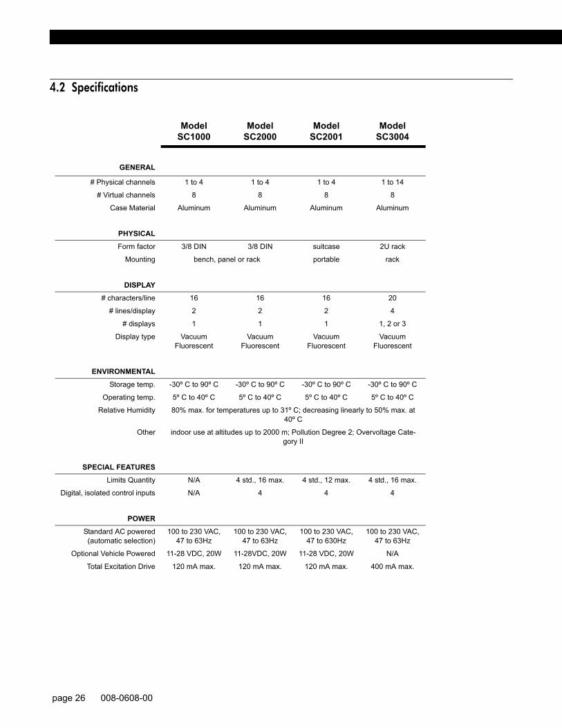
4.2 Specifications
Model SC1000
Model SC2000
Model SC2001
Model SC3004
GENERAL
# Physical channels 1 to 4 1 to 4 1 to 4 1 to 14
# Virtual channels 8 8 8 8
Case Material Aluminum Aluminum Aluminum Aluminum
PHYSICALForm factor 3/8 DIN 3/8 DIN suitcase 2U rack
Mounting bench, panel or rack portable rack
DISPLAY# characters/line 16 16 16 20
# lines/display 2 2 2 4
# displays 1 1 1 1, 2 or 3
Display type VacuumFluorescent
VacuumFluorescent
VacuumFluorescent
VacuumFluorescent
ENVIRONMENTALStorage temp. -30º C to 90º C -30º C to 90º C -30º C to 90º C -30º C to 90º C
Operating temp. 5º C to 40º C 5º C to 40º C 5º C to 40º C 5º C to 40º C
Relative Humidity 80% max. for temperatures up to 31º C; decreasing linearly to 50% max. at 40º C
Other indoor use at altitudes up to 2000 m; Pollution Degree 2; Overvoltage Cate-gory II
SPECIAL FEATURESLimits Quantity N/A 4 std., 16 max. 4 std., 12 max. 4 std., 16 max.
Digital, isolated control inputs N/A 4 4 4
POWERStandard AC powered
(automatic selection)100 to 230 VAC,
47 to 63Hz100 to 230 VAC,
47 to 63Hz100 to 230 VAC,
47 to 630Hz100 to 230 VAC,
47 to 63Hz
Optional Vehicle Powered 11-28 VDC, 20W 11-28VDC, 20W 11-28 VDC, 20W N/A
Total Excitation Drive 120 mA max. 120 mA max. 120 mA max. 400 mA max.
page 26 008-0608-00

Chassis M
odels4
4.3 Models SC1000 and SC2000
4.3.1 Differences Model SC1000 instruments do not include peak/valley capture or limits features.All other SC instruments include peak/valley capture and 4 limit (“alarm”) outputs.
4.3.2 External Arrangement The external arrangement of the AC powered SC1000 and SC2000 is givenbelow.
Figure 4-1: External Arrangement of AC powered SC1000 and SC2000
4.3.3 Rear Panel The pinout for the 25-pin System connector is provided later in this chapter. Thepinouts for the individual channels are located in the chapter for that channel.
4.3.4 Panel Mounting The panel cutout size conforms to the 3/8 DIN standard. Panel-Mounting Jacks(order code AA928) are available that slide into two slots at the sides of the instru-ment. Use the following procedure to mount an SC1000 or SC2000 into a panel.
0123456789ABCDEF
0123456789ABCDEF
SC Series Instruction Manual page 27

Figure 4-2: Panel Cutout Drawing for SC1000 & SC2000 (not to scale)
Step 1: In the panel or rack, cut a hole as shown above. The panel may be up to 1/4”in thickness.
Step 2: Use an 0.062" Allen wrench to remove two set screws that hold the Panel-Mounting Jacks to the case. To do this, insert the wrench into the side slots atthe rear. Remove the screws completely.
Step 3: Remove the Panel-Mounting Jacks by sliding them toward the rear. If the jacksdon't slide easily, tap them gently.
Step 4: Put the instrument through the hole in the panel.
Step 5: Reinsert the Panel-Mounting Jacks into the slide slots. Slide them as fartoward the panel as possible.
Step 6: Reinsert the setscrews and tighten them. This will force the Panel-MountingJacks toward the rear side of the panel, drawing the instrument tightly intoplace.
4.3.5 Rack Mounting A Rack Mounting Kit (order code AA934) is available for mounting a single SC1000 orSC2000 into a 19”, 2U rack. It includes the Panel-Mounting Jacks described above aswell as the 19” rack panel.
4.3.6 Bench Mounting If bench mounting the instrument, you may want the optional carrying handle/benchstand (order code AA926).
4.3.7 Case Removal
WARNINGDisconnect the power cord and all cables from the instrument before attempt-ing to remove the case.Failure to comply with these instructions could result in death or serious injury.
page 28 008-0608-00

Chassis M
odels4
Removal of rear panel The rear panel must be removed in order to install or remove channels.
Step 1: Remove the four black Phillips-head machine screws that secure the backpanel of the instrument to the case. These screws are located on the rear ofthe case, one at each of the four corners.
Step 2: Remove the cable shield connection screw to allow the installation orremove of channels per “Input or Output Channel Installation Procedure” onpage 42.
Remove of case from entire circuit board assembly
Step 1: Remove the two Phillips-head screws that secure the front panel.
Step 2: Remove the front panel and disconnect its two connecting cables.
Step 3: Remove the four black Phillips-head machine screws that secure the backpanel of the instrument to the case. These screws are located on the rear ofthe case, one at each of the four corners. Do not remove the cable shieldconnection screw in the center.
Step 4: The circuit boards will slide out of the rear of the case as a unit.
4.3.8 Internal Arrangement The figure below shows the names and locations of the printed circuit boards.
Figure 4-3: Internal Arrangement of SC1000 and SC2000
Below is a description of each printed circuit board.
• The SensoBus Backplane Board serves as the connection between all
CAUTIONUse a #0 Phillips screwdriver on the black screws to avoid damaging them.Failure to comply with these instructions may result in product damage.
Front Panel/Display BoardAssembly
Power SupplyBoard
SensoBus BackplaneBoard
Up to 4 Input or OutputChannel boards
(1 shown)
MicroprocessorBoard
Rear Panel
SC Series Instruction Manual page 29
boards in the instrument.• The Front Panel/Display Board Assembly contains the display and all front panel
controls.• The Power Supply Board contains the +15V, -15V and +5V power supplies.• The Microprocessor Board contains the microprocessor, ROM software storage
chip, and the System connector. • The Hardware Input/Output Channel Boards plug into the remaining four slots
of the SensoBus Backplane Board.
4.3.9 Cleaning Turn off the instrument and unplug all connectors. Use a soft cloth or tissue and amild cleaner. Do not use liquid or aerosol cleaners. Do not allow any cleaner insidethe instrument.
4.3.10 Vehicle Power Option
Model SC1000 and SC2000 instruments are available with a vehicle power option foroperation with batteries and linear DC power supplies. See “Specifications” onpage 26 voltage and power requirements.
4.3.11 Fuse Replacement
The power-line fuses of AC-powered instruments are located within the instrument'spower entry module on the rear panel. Use two 2A, 250V fast-blow fuses (p/n 029-3026-00).
NOTICEDue to the momentary startup inrush current of the instrument’s power supply, the use of switching power supplies with the SC are not recommended.
page 30 008-0608-00
Chassis M
odels4
4.4 Model SC2001
4.4.1 Differences Model SC2001 instruments are SC2000 instruments housed in a portable case.
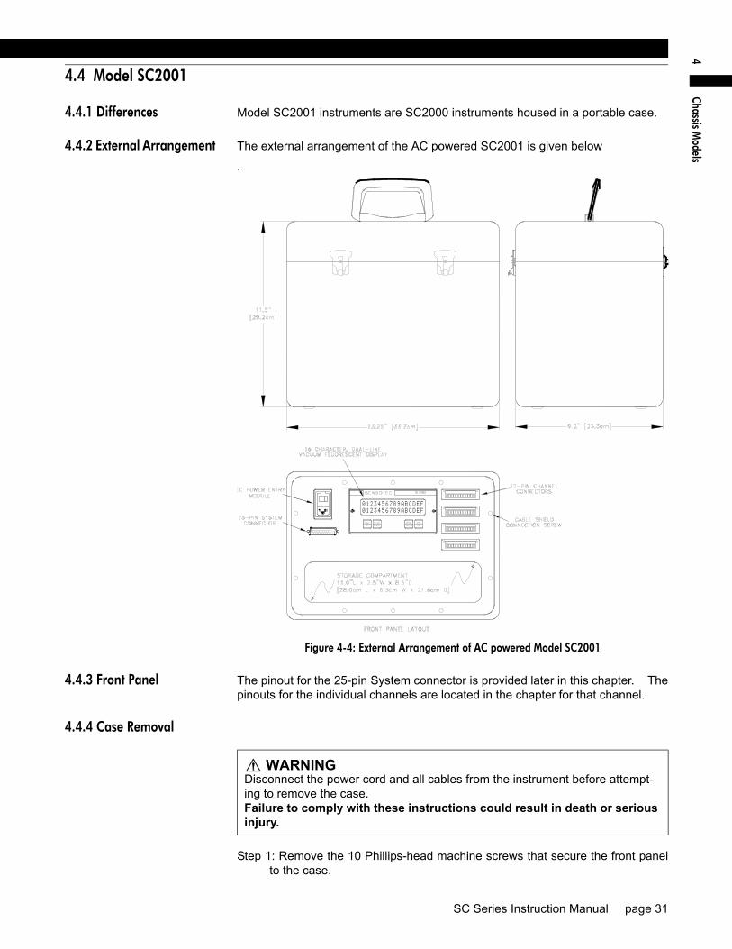
4.4.2 External Arrangement The external arrangement of the AC powered SC2001 is given below
.
Figure 4-4: External Arrangement of AC powered Model SC2001
4.4.3 Front Panel The pinout for the 25-pin System connector is provided later in this chapter. Thepinouts for the individual channels are located in the chapter for that channel.
4.4.4 Case Removal
Step 1: Remove the 10 Phillips-head machine screws that secure the front panelto the case.
0 12 3 4 5 6 7 8 9 A B C D E F
0 12 3 4 5 6 7 8 9 A B C D E F
WARNINGDisconnect the power cord and all cables from the instrument before attempt-ing to remove the case.Failure to comply with these instructions could result in death or serious injury.
SC Series Instruction Manual page 31

Step 2: Pull the front panel assembly out of the case.
Step 3: Proceed with Model SC2000 “Case Removal” on page 28.
4.4.5 Internal Arrangement See the Model SC2000 “Internal Arrangement” on page 29.
4.4.6 Cleaning Turn off the instrument and unplug all connectors. Use a soft cloth or tissue and amild cleaner. Do not use liquid or aerosol cleaners. Do not allow any cleanerinside the instrument.
4.4.7 Vehicle Power Option The Model SC2001 is available with a vehicle power option for operation with bat-teries and linear DC power supplies. See “Specifications” on page 26 voltage andpower requirements..
4.4.8 Fuse Replacement The power-line fuses of AC-powered instruments are located within the instru-ment's power entry module on the rear panel. Use two 2A, 250V fast-blow fuses(p/n 029-3026-00).
NOTICEDue to the momentary startup inrush current of the instrument’s power supply, the use of switching power supplies with the SC are not recommended.
page 32 008-0608-00

Chassis M
odels4
4.5 Model SC3004
4.5.1 External Arrangement
Figure 4-5: External Arrangement of Model SC3004
4.5.2 Rear Panel The pinout for the 25-pin System connector is provided later in this chapter. Thepinouts for the individual channels are located in the chapter for that channel.
4.5.3 Panel Mounting The panel space necessary conforms to the EIA 19” rack-mount standard. Panelmounting ears are attached to the instrument.
4.5.4 Bench Mounting Panel mounting ears are attached to the instrument, and may be removed if theyare not needed.
0123456789ABCDEFGHIJ0123456789ABCDEFGHIJ
0123456789ABCDEFGHIJ0123456789ABCDEFGHIJ
0123456789ABCDEFGHIJ0123456789ABCDEFGHIJ0123456789ABCDEFGHIJ0123456789ABCDEFGHIJ
0123456789ABCDEFGHIJ
0123456789ABCDEFGHIJ0123456789ABCDEFGHIJ0123456789ABCDEFGHIJ
SC Series Instruction Manual page 33

4.5.5 Case Removal
Step 1: Remove the four, silver rack-mounting ears from the left and right sides.
Step 2: Remove one Phillips screw from the top of the case.
Step 3: Remove two Phillips screws from the bottom of the black case cover.
Step 4: Remove the black case cover from the instrument.
Step 5: Remove eight Phillips screws from the rear panel, including the two cableshield connection screws. NOTE: Do not remove the four screws whichsecure the cooling fan to the rear panel.
Step 6: Remove the rear panel.
4.5.6 Rear Panel The pinout for the 25-pin System connector is provided later in this chapter.
4.5.7 Internal Arrangement User installable printed circuit boards will slide out of the rear of the case once thecase and rear panel have been removed as described above.
4.5.8 Cleaning Turn off the instrument and unplug all connectors. Use a soft cloth or tissue and amild cleaner. Do not use liquid or aerosol cleaners. Do not allow any cleanerinside the instrument.
4.5.9 Fuse Replacement The power-line fuses are located within the instrument's power entry module onthe rear panel. Use two 2A, 250V fast-blow fuses (p/n 029-3026-00).
WARNINGDisconnect the power cord and all cables from the instrument before attempt-ing to remove the case.Failure to comply with these instructions could result in death or serious injury.
CAUTIONUse a #0 Phillips screwdriver on the black screws to avoid damaging them.Failure to comply with these instructions may result in product damage.
page 34 008-0608-00

System
Connector5
Chapter 5System Connector
5.1 Introduction
The 25-pin D-subminiature System connector is used for the following:
• Communication by RS-232 or RS-485. RS-232 DCE standard designations have been maintained.
• Digital Function Inputs, such as for resetting tare, peak and latched limits• Open-collector digital Limit Outputs for limits 1 through 4 (not available on
Model SC1000).
SC Series Instruction Manual page 35

5.2 System Connector Pinout
The Limit Output pins and Function Input pins are electrically isolated from the rest ofthe instrument.
The RS-232 and RS-485 communications pins are electrically isolated from the rest ofthe instrument.
The RS-232 and RS-485 interfaces are exclusive; an instrument cannot have both.
Table 5-2: System Connector
Pin Name Function Input/Output Reference Pin
1 N/C No Connection N/A
2 RS-232 IN RS-232 Data In Input 7
3 RS-232 OUT RS-232 Data Out Output 7
4 CTS RS-232 Clear to Send (connected to pin 5) N/A N/A
5 RTS RS-232 Request to Send (connected to pin 4) N/A N/A
6 DSR RS-232 Data Set Ready Output 7
7 GND RS-232/RS-485 reference Reference -
8 DCD RS-232 Data Carrier Detect (not connected) N/A N/A
9 FUNC 2 Function Input #2:.Clear Peak/Valley & Limits Input 19
10 FUNC 1 Function Input #1: Tare Off for all channels Input 19
11 FUNC 0 Function Input #0 Input 19
12 RS-485 TB RS-485 Transmit B Output 7
13 RS-485 TA RS-485 Transmit A Output 7
14 L1 Limit 1 Output (Open Collector) Output 19
15 L2 Limit 2 Output (Open Collector) Output 19
16 L3 Limit 3 Output (Open Collector) Output 19
17 L4 Limit 4 Output (Open Collector) Output 19
18 N/C No Connection N/A
19 DGND DGND (Digital Ground) Reference
20 DTR RS-232 Data Terminal Ready (not connected) N/A N/C
21 FUNC 3 Function Input #3: Tare On for all channels Input 19
22 RI RS-232 Ring Indicator (pulled up to 5V) Output
23 N/C No Connection N/A N/C
24 RS-485 RB RS-485 Receive B Input 7
25 RS-485 RA RS-485 Receive A input 7
page 36 008-0608-00

System
Connector5
5.3 Function Input Pins
5.3.1 Overview To use a Function Input pin (9, 10, 11 or 21), connect it to the DGND (pin 19) momen-tarily. This can be accomplished by a push button switch, relay contact closure, orPLC output.
Usually, the Function Input pins perform the default actions described in the “SystemConnector Pinout” on page 36. However, a SensoCode program running on a Mathe-matics Virtual Channel may replace these default actions. Consult the CustomerInformation Sheet included with your instrument for details.
5.3.2 Example For example, assume that you wish to use Function Input #3 to tare all channels in theinstrument simultaneously. Connect a push-button switch as shown below.
Figure 5-1: Function Input Example
SC Series Instruction Manual page 37

5.4 Limit Output Pins
5.4.1 Overview An open-collector output is a transistor logic output that can be used to control DCloads, drive opto-isolators or relays, or interface directly to logic circuitry. They act verymuch like switches: low resistance when turned on and high resistance when turnedoff. You can use them as you would a dry relay contact, with the following restrictions:
• The voltage applied must be DC• The polarity of the DC voltage must be observed• Maximum voltage: 50VDC• Maximum power: 2.0W
When Limits 1, 2, 3, or 4 are activated, the corresponding open-collector Limit Outputpin on the System connector will be connected to the DGND (Digital Ground) pin.However, a SensoCode program running on a Mathematics Virtual Channel may over-ride this behavior. Consult the Customer Information Sheet included with your instru-ment for details.
5.4.2 Example For example, assume that a remote indicator is to be lighted when Limit 1 is activated.An external 24 VDC power supply connects to the indicator.
When Limit 1 is deactivated, there is high resistance between the Limit 1 Output pinand the DGND (Digital Ground) pin; little current flows in the circuit and the light is off.When Limit 1 is activated, there is low resistance between the Limit 1 Output pin andthe DGND (Digital Ground) pin; the light turns on.
The resistor limits the current flowing in the circuit when the light is lighted to 48 mA.According to Ohm’s Law:
Lights or other indicators have voltage, current, and/or power ratings that must beobserved in order to avoid damaging them.
Figure 5-2: Open-Collector Output Example
I VR---=
48mA 24V500Ω-------------=
page 38 008-0608-00

System
Connector5
SC Series Instruction Manual page 39

page 40 008-0608-00

System
Menu
6
Chapter 6System Menu
6.1 Overview
The System menu allows you to examine and change settings that affect thechassis of the SC instrument. You can view the internal software revision and theinstrument’s configuration (i.e. what types of cards are installed in each channel).
Detailed instructions on operating the SC instrument in the SETUP Menu modecan be found in “SETUP Menu mode” on page 23. A diagram of all menus islocated in the “Setup Menu Reference” on page 157.
6.2 Menu Items
6.2.1 SOFTWARE REVISION Menu Item
This displays the software part number and revision that is resident in the Micro-processor Board of the SC instrument.
6.2.2 CONFIGURATION Sub-Menu
When selected, a sub-menu is displayed which lists all available channels in anSC Series instrument. By pressing [ENTER] when a channel number is dis-played, the card type installed in that channel is shown. If a card is not installed inthat channel, the message “NOT INSTALLED” is shown. Press [ENTER] again toreturn to the sub-menu listing of all channels.
6.2.3 DIAGNOSTICS Sub-Menu
This sub-menu allows exercising and monitoring of the System connector’s outputand input pins.
OUTPUT n, PIN nn Menu Items These menus items are used to select an output pin to turn “on” (connected to pin19) or “off” (disconnected from pin 19). The output pins are updated immediately.
INPUT TEST Menu Item When this item is selected, the status of all four digital inputs are continuouslyscanned and displayed. A “0” means that an input is not connected to pin 19 (notasserted), and a “1” means that it is connected (asserted). Press any button toexit this operation.
SCAN TIME Menu Item When selected, this menu item displays the time, in seconds, that it last took forthe chassis to service all of the channels. In the RUN mode, the chassis readseach channel’s track, peak and valley value sequentially. After each channel hasbeen serviced, the limits are processed.
The value displayed is obtained from the last execution of the RUN mode prior toentering the SETUP menu mode. If you enter the SETUP mode immediately afterpower up, the display will read “NOT AVAILABLE”.
SC Series Instruction Manual page 41

6.2.4 INSTALL CHANNEL Menu Item
This menu item will add an Input, Output or Virtual channel as the next highest chan-nel number in the system.
Input or Output Channel Installation Procedure
Before installing an Input or Output card, make certain that you know the “card type”(a two-digit hexadecimal number) of the card you wish to install.
Use the following procedure to install an Input or Output card:
1) When the instrument is in the RUN mode, use the [ENTER] button to change which channel the display is monitoring. Note the highest channel number that is presently installed. The new circuit card for the new channel will be installed as the next channel number.
2) Examine the circuit card to be installed and orient it as shown below. On it you will find the address jumper block.
Figure 6-1: Address Jumper Block Location
3) Change both address jumpers to match the next available channel in the instrument according to the chart below. Do not skip any channel numbers.
Figure 6-2: Address Jumper Settings
NOTICEInstalling a channel will cause it to use the “default” or “empty” configuration information for that channel. All other channels are unaffected.Any calibration data, SensoCode mathematics programs, display setup, or other information for that channel will be erased to default values.
CAUTIONUse Electrostatic Discharge (ESD) precautions when unpacking and handling circuit boards.Failure to comply with these instructions may result in product damage.
page 42 008-0608-00

System
Menu
6
Input Channels, Output Channels and Virtual Channels (such as Mathematics Channels and Split Display Channels) all require an unique address.
4) Turn the instrument off and remove the power cord from the power source.
5) Find the “Case Removal” in Chapter 4 “Chassis Models” on page 25 that matches the particular chassis model. Follow the directions and remove the rear panel.
6) Locate an unused 42-pin SensoBus connector on the SensoBus mother board and make certain that all of its pins are not bent out of shape. It does not matter into which slot you install the card as the addressing is imple-mented with the address jumpers. However, it is most convenient to match the card’s address with the channel numbers silk-screened on the rear panel.
7) Install the card into an unused 42-pin SensoBus connector on the Senso-Bus mother board. Make certain the card is fully seated.
8) Replace the rear panel.
9) Re-connect the power cord to the power source. Turn the instrument on.
10) Enter the SETUP menu mode, then select “SYSTEM MENU -> INSTALL CHANNEL”. The instrument will then present a menu of card types available for installa-tion.
11) Use the [UP] and [DOWN] buttons to select the card type of the card you wish to install. After you select the card type to be installed, you are asked “ARE YOU SURE?”. To cancel this operation, select “NO” or press the [EXIT] but-ton. If “YES” is selected, “WORKING...” is displayed and the installation will com-mence.
12) If the installation was successful, “DONE” will be displayed. If the installation failed, you will see one of the following messages:
“SYSTEM IS FULL”: There are no unused channels available in the instrument.
“WON’T INSTALL”: The Output Relay card type you selected to install does not match the next available set of Limits. For example, the Limit 09-12 card type will not install unless the Limit 05-08 card type has been installed.
“ERROR 28 ON CH.xx”: The instrument could not communicate with the card’s EEPROM memory. This is usually caused by the address jumpers being set incorrectly or if the card is not physically inside the chassis.
Virtual Channel Installation Procedure
Use the following procedure to install a Virtual Channel:
1) Enter the SETUP menu mode, then select “SYSTEM MENU -> INSTALL CHANNEL”. The instrument will then present a menu of card types available for installa-tion.
2) Select the card type of the card you wish to install. After you select the card type to be installed, you are asked “ARE YOU SURE?”. To cancel this opera-tion, select “NO” or press the [EXIT] button. If “YES” is selected, “WORKING...” is displayed an the installation will commence.
3) If the installation was successful, “DONE” will be displayed. If the installation failed, you will see one of the following messages:
“CAN’T INSTALL”: There is no more memory available for Virtual channels.
“SYSTEM IS FULL”: There are no unused channels available in the instrument.
After installing a Mathematics Virtual channel, you must re-load the SensoCodeprogram into the channel with a computer running the “SensoCom Instrument Util-ity Software”. See “Mathematics Virtual Channel” on page 143 for more informa-tion.
SC Series Instruction Manual page 43

6.2.5 DELETE CHANNEL Menu Item
This menu item will delete the last channel in the instrument. Before deletion occurs,the number of the channel to be deleted is displayed and you are asked “ARE YOU SURE”.To cancel this operation, select “NO” or press the [EXIT] button. If “YES” is selected,the last channel in the system will be deleted.
After a hardware channel has been deleted, you can safely physically remove it fromthe chassis. See “Case Removal” on page 28 for SC1000 and SC2000 instruments.See “Case Removal” on page 34 for SC3004 instruments.
6.2.6 DEFAULT CHANNEL Menu Item
This menu item will reset all settings for the channel you select to their factory defaultvalues. Before the channel settings are reset, you are asked “ARE YOU SURE?”. To cancelthis operation, press the [EXIT] button. If “YES” is selected, the channel’s settings willbe reset.
NOTICERe-installing a deleted channel will erase all of its configuration information!
NOTICEDefaulting a channel is an operation that cannot be undone. All calibration information and other settings will be erased.
page 44 008-0608-00

System
Menu
6
SC Series Instruction Manual page 45

page 46 008-0608-00

Serial Com
munications
7
Chapter 7Serial Communications
7.1 Overview
The SC Series instruments are designed to communicate with a remote computersystem or terminal for the purpose of transferring data values from the instrumentto the remote system. The remote computer or terminal also can control many ofthe functions performed by the instrument.
This chapter is a brief introduction to serial communications with SC Series instru-ments. A separate instruction manual is available to assist with the hookup andwiring for data communications as well as provide detailed information of all theavailable commands. Ask for manual 008-0610-00, “SC Series CommunicationsGuide” or download it from http://www.honeywell.com/sensotec.
7.2 Wiring
The System connector on the instrument’s rear panel is used, among other things,for serial communications. See “System Connector” on page 35 for wiring infor-mation.
All of the serial communications pins on the 25-pin System connector have 500Vof electrical isolation from all other pins and connectors on the instrument. Addi-tionally, all serial communications pins are protected against electrostatic dis-charge (ESD).
SC Series Instruction Manual page 47

7.3 Communications Protocol
7.3.1 RS-232 vs. RS-485 SC Series instruments are available with either of two communications protocols, RS-232 or RS-485. Only one of these can be installed at a time at the factory.
• RS-232 provides for only one receiver and transmitter per loop, and a loop length of no more than 50 feet.
• RS-485 allows up to 32 devices per loop, and a loop length of no more than 4000 feet. All devices receive messages in parallel on the line, the so-called “multi-drop” system. To avoid garbled transmissions, only one device should respond to a particular message. Therefore, every device on the loop must have a unique address.
If you have an instrument with more than one channel, transmission must beaddressed to the appropriate channel within the instrument.
7.3.2 Parameters All SC instruments use no parity, 8 data bits, and 1 stop bits (“N,8,1”) for serial com-munications. Baud rates available are 300, 600, 1200, 2400, 4800, 9600, 19200and 38400. As shipped from the factory, all instruments are set at 9600 baud. Thebaud rate can be selected though the front panel.
page 48 008-0608-00

Serial Com
munications
7
7.4 Serial Com Menu
7.4.1 Overview The Serial Com menu allows you to examine and change the settings for serial com-munications as well as test the communications link.
Detailed instructions on operating the SC instrument in the SETUP Menu mode canbe found in “SETUP Menu mode” on page 23. A diagram of all menus is located in“Setup Menu Reference” on page 157.
7.4.2 INTERFACE Menu Item
This menu item indicates which serial communications interface is installed in theinstrument: “RS-232” or “RS-485”.
7.4.3 ADDRESS Menu Item
This allows you to examine and change the two-character address that the instrumentwill respond to. The default address of “00” (ASCII codes decimal 30, decimal 30).
7.4.4 BAUD RATE Menu Item
This allows you to examine and change the baud rate that the instrument uses forserial communications. The default baud rate is 9600.
7.4.5 AUTO LINE-FEED Menu Item
This allows you to examine the setting (on/off) of the auto line-feed function. Whenset to “on”, a line-feed character (ASCII code decimal 10) is transmitted just before thecarriage return (ASCII code decimal 13) that signifies the end of the instrument’sresponse.
If the instrument is connected to a dumb terminal or printer, inserting a line feed beforethe carriage return will make each message sent by the instrument appear on a sepa-rate line and thus be easier to read.
The default setting is “on”.
7.4.6 TRANSMIT TEST Menu Item
When this menu item is selected, the instrument immediately transmits the message“ADDRESS nn TEST” where “nn” is the two-character address of the instrument. Then themessage “MESSAGE SENT” is shown on the display. This helps detect wiring or other prob-lems with serial communications from the instrument to the computer or PLC.
7.4.7 LEAVE MENU Menu Item
When the menu item is displayed, press [ENTER] to leave this menu. Press [EXIT] toreturn to the RUN mode.
SC Series Instruction Manual page 49

page 50 008-0608-00

Display M
enu8
Chapter 8Display Menu
8.1 Overview
The Display menu allows you to examine and change settings that affect the oper-ation of the display of the SC instrument. You can change which channel is dis-played when the instrument is powered-up and what information is shown on thelower line of SC1000, SC2000 and SC2001 instruments.
Detailed instructions on operating the SC instrument in the SETUP Menu modecan be found in “SETUP Menu mode” on page 23. A diagram of all menus islocated in the “Setup Menu Reference” on page 157.
8.2 Menu Items for Models SC1000, SC2000, SC2001
These instruments have a dual-line display which consists of an upper line and alower line.
8.2.1 UPPER CHANNEL Menu Item
Specifies the channel that is displayed on the upper line when the instrument ispowered-up.
To change whether the channel’s track, peak or valley data value is displayed onpower-up, use the channel’s “OPERATION -> POWER-ON SOURCE” menu item.
8.2.2 LOWER CHANNEL Menu Item
Specifies the channel that is displayed on the lower line when the “LOWER MODE”menu item is set to “CHANNEL”.
To change whether the channel’s track, peak or valley data value is displayed onpower-up, use the channel’s “OPERATION -> POWER-ON SOURCE” menu item.
8.2.3 LOWER MODE Menu Item
Determines what is displayed on the lower line. The choices are:
• “BLANK” means that nothing is displayed.• “LIMIT 01-04” means that the status of Limit 1, Limit 2, Limit 3, and Limit 4 are
displayed as described in “Indicator Lights” on page 21• “CHANNEL” means that the channel specified with the “LOWER CHANNEL” menu item
is displayed.
8.2.4 DISPLAY DISABLE Menu Item
Determines if the display is enabled or not. In some applications, the display isnot used in order to reduce power consumption; the instrument is then completelycontrolled with the Serial Communications interface. The choices are:
• “OFF” means that the display operates normally.• “ON” means that the display is blanked after the instrument is powered up.
Pressing any button on the front panel will temporarily re-enable the display until the instrument is reset.
8.3 Menu Items for Model SC3004
8.3.1 POWER-ON CHANNEL Menu Item
Specifies the channel that is selected when the instrument is powered up.
To change whether the channel’s track, peak or valley data value is displayed onpower-up, use the channel’s “OPERATION -> POWER-ON SOURCE” menu item.
SC Series Instruction Manual page 51

page 52 008-0608-00

Lim
its9
Chapter 9Limits
9.1 Understanding Limits, Set Points and Return Points
Limits are signal levels at which some action (such as a light to come on or go out,or a switch to close) is desired to take place. The point at which this action takesplace is the SET POINT. The RETURN POINT is the point at which the action thattook place at the SET POINT returns to its original state.
If the SET POINT and RETURN POINT are identical and the signal level ischanging slowly near these points, “chatter” may result and the limit rapidly ener-gizes and de-energizes. To keep this from happening, we can specify the SETPOINT at which the action would occur as well as the RETURN POINT where wewant the action to cease. If the amount of “dead band” between these two valuesis more than the expected noise, the desired action will take place only once. TheSET POINT and the RETURN POINT should always be separated to insure thatsmall amounts of noise on the signal will not become a problem.
A good general rule for SET POINT and RETURN POINT values is that theyshould be separated by at least one percent of the full-scale value.
SC Series Instruction Manual page 53

9.2 Limit Operation
9.2.1 Actions When Activated
When Limits 1, 2, 3, or 4 are activated, the following actions occur:
• The front panel light for the limit will illuminate.• The corresponding open-collector Limit Output pin on the System connector will
be connected to the DGND (Digital Ground) pin.• If a Relay Output channel is installed, the relay for the limit will activate.
A Relay Output channel can be installed for Limits 5, 6, 7, and 8. When these limitsare activated, the following actions occur:
• If the display is monitoring the channel of this Relay Output channel, the display will indicate the status of these limits.
• On a Model SC3004, the front panel light for the limit will illuminate.• The relay for the limit on this Relay Output channel will activate.
A Relay Output channel can be installed for Limits 9, 10, 11 and 12. When these limitsare activated, the following actions occur:
• If the Relay Output channel is displayed, the display will indicate the status of these limits.
• The relay for the limit on this Relay Output channel will activate.
A Relay Output channel can be installed for Limits 13, 14, 15 and 16. When these lim-its are activated, the following actions occur:
• If the Relay Output channel is displayed, the display will indicate the status of these limits.
• The relay for the limit on this Relay Output channel will activate.
9.2.2 Scan Time The “scan time” or update rate of the limits depends on how many channels areinstalled in the instrument. To determine the scan time of the limits for your particularinstrument, see “SCAN TIME Menu Item” on page 41.
page 54 008-0608-00
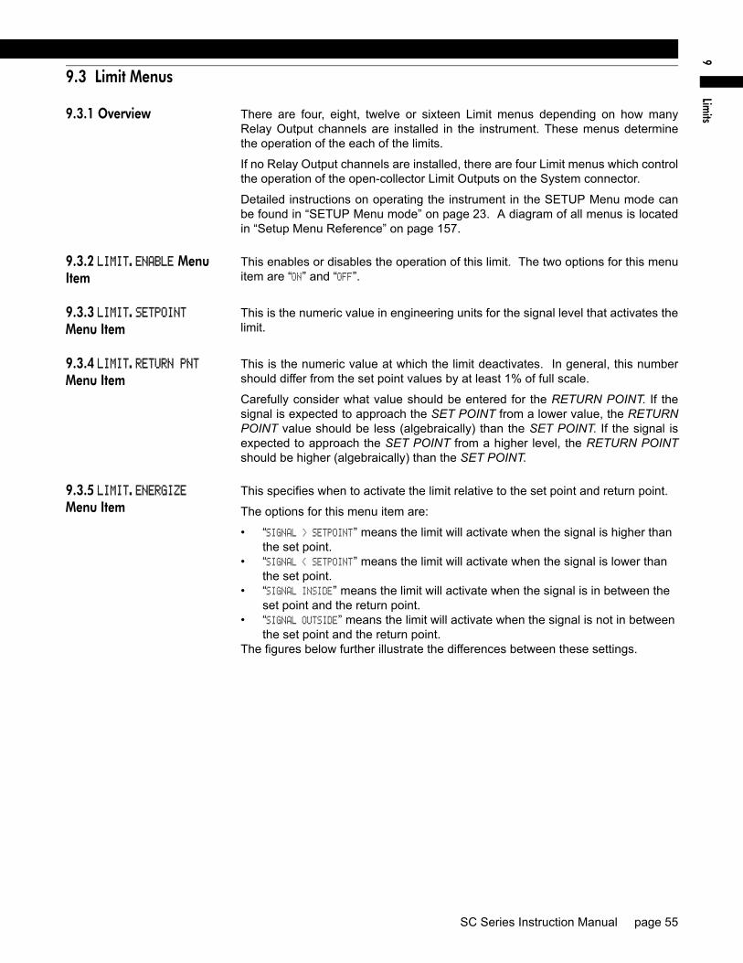
Lim
its9
9.3 Limit Menus
9.3.1 Overview There are four, eight, twelve or sixteen Limit menus depending on how manyRelay Output channels are installed in the instrument. These menus determinethe operation of the each of the limits.
If no Relay Output channels are installed, there are four Limit menus which controlthe operation of the open-collector Limit Outputs on the System connector.
Detailed instructions on operating the instrument in the SETUP Menu mode canbe found in “SETUP Menu mode” on page 23. A diagram of all menus is locatedin “Setup Menu Reference” on page 157.
9.3.2 LIMIT.ENABLE Menu Item
This enables or disables the operation of this limit. The two options for this menuitem are “ON” and “OFF”.
9.3.3 LIMIT.SETPOINT Menu Item
This is the numeric value in engineering units for the signal level that activates thelimit.
9.3.4 LIMIT.RETURN PNT Menu Item
This is the numeric value at which the limit deactivates. In general, this numbershould differ from the set point values by at least 1% of full scale.
Carefully consider what value should be entered for the RETURN POINT. If thesignal is expected to approach the SET POINT from a lower value, the RETURNPOINT value should be less (algebraically) than the SET POINT. If the signal isexpected to approach the SET POINT from a higher level, the RETURN POINTshould be higher (algebraically) than the SET POINT.
9.3.5 LIMIT.ENERGIZE Menu Item
This specifies when to activate the limit relative to the set point and return point.
The options for this menu item are:
• “SIGNAL > SETPOINT” means the limit will activate when the signal is higher than the set point.
• “SIGNAL < SETPOINT” means the limit will activate when the signal is lower than the set point.
• “SIGNAL INSIDE” means the limit will activate when the signal is in between the set point and the return point.
• “SIGNAL OUTSIDE” means the limit will activate when the signal is not in between the set point and the return point.
The figures below further illustrate the differences between these settings.
SC Series Instruction Manual page 55
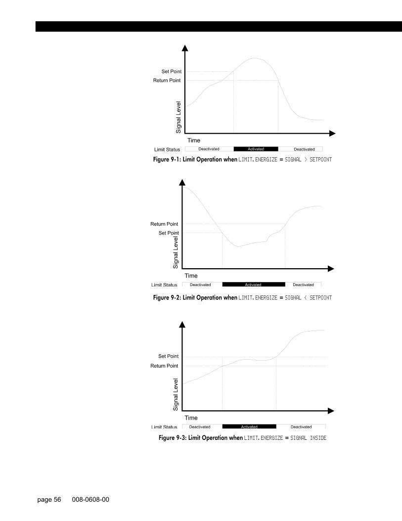
Figure 9-1: Limit Operation when LIMIT.ENERGIZE = SIGNAL > SETPOINT
Figure 9-2: Limit Operation when LIMIT.ENERGIZE = SIGNAL < SETPOINT
Figure 9-3: Limit Operation when LIMIT.ENERGIZE = SIGNAL INSIDE
page 56 008-0608-00

Lim
its9
Figure 9-4: Limit Operation when LIMIT.ENERGIZE = SIGNAL OUTSIDE
9.3.6 LIMIT.LATCHING Menu Item
This specifies whether to latch the activated limit so that only manually clearing thelimit will deactivate it. A latched limit can be manually cleared by pressing the[CLEAR] button, sending the “F8” serial communications command, or by using theFunction Input #2 (Clear Peak/Valley & Limits pin on the System Connector. See“Function Input Pins” on page 37.
The options for this menu item are:
• “ON” means that once a signal activates the limit, the limit will remain activated until it is reset.
• “OFF” means that the limit will deactivate immediately when the signal crosses the return point.
9.3.7 LIMIT.CHANNEL Menu Item
This specifies the channel that is monitored by this limit.
9.3.8 LIMIT.SOURCE Menu Item
This designates the data source of the channel monitored by this limit. Each channelhas three data sources: the live tracking value (TRACK), its highest value (PEAK),and its lowest value (VALLEY).
The options for this menu item are:
• “TRACK” means the live tracking value of the channel. • “PEAK” means the highest value of the channel since the peak/valley detector was
last cleared.• “VALLEY” means the lowest value of the channel since the peak/valley detector was
last cleared.
9.3.9 LEAVE MENU Menu Item
When the menu item is displayed, press [ENTER] to leave this menu. Press [EXIT] toreturn to the RUN mode.
SC Series Instruction Manual page 57

page 58 008-0608-00

Strain-G
age Input Channel10
Chapter 10Strain-Gage Input Channel
10.1 Features
The Strain-Gage Input channel provides a DC excitation voltage to and acceptsmillivolt signals from strain-gage transducers. These millivolt signals are digitized,converted into engineering units, and placed into the track, peak and valley datavalues of the channel. Setup and calibration of the channel can be made manu-ally through the SETUP mode or automatically if the transducers are equippedwith Signature Calibration. See “What is Signature Calibration?” on page 14.
The analog-to-digital converter input circuit is ratiometric to the excitation voltage,features adjustable digital, low-pass filtering, 12- to 18-bit resolution (dependingon the filter setting) and has several different mV/V input ranges. These manyinput ranges allow ±50,000 count resolution (at the slowest filter setting) across awide variety of mV/V input ranges.
Three methods of calibrating the Strain-Gage Input channel to the transducer areavailable: known-load calibration, shunt calibration and mV/V calibration. Thebenefits of each are discussed in “CALIBRATION TYPE Menu Item” on page 67.
Two rear panel control inputs can be field-configured for such functions as remotetare, disabling peak/valley detection and clearing the peak/valley values. A volt-age or current digital-to-analog output is also provided.
Many diagnostic functions are performed automatically to insure correct wiringand operation of the transducer.
FP2000 Transducers The Strain-Gage Input channel has its own internal shunt resistor for use in ShuntCalibration. It is not compatible with FP2000 mV/V output transducers that areequipped with “Buffered Shunt Calibration”. If you wish to use Shunt Calibrationwith an FP2000 transducer, use an FP2000 with Buffered Shunt cal and amplifiedoutput (e.g. 5 VDC, 10 VDC or 4-20mA) connected to an SC's High-Level Inputchannel.
SC Series Instruction Manual page 59

10.2 Wiring
Connect the transducer to a Strain-Gage Input channel by wiring it to the 12-pin con-nector of that channel. The Customer Information Sheet that shipped with the instru-ment describes which cards are installed in each channel. The pin-out for thisconnector is shown on the following table.
The Analog Output and Analog Return pins are electrically isolated from all other pinson the instrument.
The maximum recommended cable length to a Signature Module is 100 feet [30m].
Figure 10-1: Unamplified Transducer Connection to Strain-Gage Input Channel
Table 4-3: Strain-Gage Input Channel Pin Connections
Pin Label Function Reference Pin
1 (top) +EXC (+)Excitation 102 +SEN (+)Sense 103 -SEN (-)Sense 104 -EXC (-)Excitation 105 +SIG (+)Signal 106 -SIG (-)Signal 107 +OUT Analog Output 88 -OUT Analog Return -9 +MEM (+)Signature 10
10 -MEM (-)Signature / Digital Ground -11 AUX1 Auxiliary Function 1
(connect to pin 10 to activate)10
12(bottom)
AUX2 Auxiliary Function 2 (connect to pin 10 to activate)
10
NOTICEIf you are not using remote sensing of excitation, jumper (+)Sense to (+)Excita-tion and (-)Sense to (-)Excitation. If nothing is connected to (+)Sense and (-)Sense, the instrument will enter the ERROR mode with error code 46.
page 60 008-0608-00

Strain-G
age Input Channel10
10.3 Calibration Procedure
If you are not familiar with operating the instrument in the SETUP menu mode,see “SETUP Menu mode” on page 23. A listing of all menu items is given in“Setup Menu Reference” on page 157.
Step 1: Wire the transducer to the channel’s connector.See “Wiring” on page 60 for details.
Step 2: Enter the CALIBRATION TYPE. There are three methods that can be used to calibrate the transducer to theInput Channel. Each has advantages and disadvantages as described in“CALIBRATION TYPE Menu Item” on page 67. It is important to know yourapplication in order to select the appropriate calibration type.
Step 3: Enter the CALIBRATION DATA.If your transducer has Signature Calibration, you don’t need to enter thesevalues as they are entered automatically. If your transducer was ordered and shipped along with the instrument, youdon’t need to enter these values as they have been entered at the factory.Otherwise, consult the Certificate of Calibration for the transducer whenentering information in the CALIBRATION DATA sub-menu.
Step 4: Perform the calibration.Otherwise, use the CALIBRATE menu item to start the calibration process. Youwill be prompted to apply loads to the transducer as required.
SC Series Instruction Manual page 61
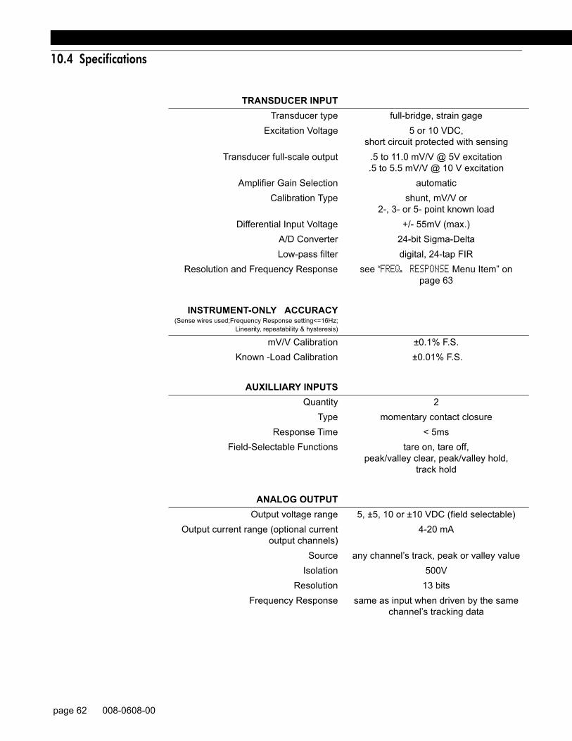
10.4 Specifications
TRANSDUCER INPUTTransducer type full-bridge, strain gage
Excitation Voltage 5 or 10 VDC,short circuit protected with sensing
Transducer full-scale output .5 to 11.0 mV/V @ 5V excitation.5 to 5.5 mV/V @ 10 V excitation
Amplifier Gain Selection automatic Calibration Type shunt, mV/V or
2-, 3- or 5- point known loadDifferential Input Voltage +/- 55mV (max.)
A/D Converter 24-bit Sigma-DeltaLow-pass filter digital, 24-tap FIR
Resolution and Frequency Response see “FREQ. RESPONSE Menu Item” on page 63
INSTRUMENT-ONLY ACCURACY(Sense wires used;Frequency Response setting<=16Hz;
Linearity, repeatability & hysteresis)
mV/V Calibration ±0.1% F.S.Known -Load Calibration ±0.01% F.S.
AUXILLIARY INPUTSQuantity 2
Type momentary contact closureResponse Time < 5ms
Field-Selectable Functions tare on, tare off,peak/valley clear, peak/valley hold,
track hold
ANALOG OUTPUTOutput voltage range 5, ±5, 10 or ±10 VDC (field selectable)
Output current range (optional currentoutput channels)
4-20 mA
Source any channel’s track, peak or valley valueIsolation 500V
Resolution 13 bitsFrequency Response same as input when driven by the same
channel’s tracking data
page 62 008-0608-00

Strain-G
age Input Channel10
10.5 Channel Menu
Each Strain-Gage Input channel is configured and calibrated via its channelmenu. Detailed instructions on operating the instrument in the SETUP Menumode can be found in “SETUP Menu mode” on page 23. A diagram of all menusis located in “Setup Menu Reference” on page 157.
10.5.1 OPERATION Sub-Menu
This menu controls the operation of this channel when the instrument is in theRUN mode.
AUTO-ZERO Menu Item This enables or disables the channel’s automatic zeroing function. The auto-zerofunction can be beneficial by removing the effect of slight temperature shifts in thetransducer’s output. The two options for this menu item are “ON” and “OFF”.
When enabled, the channel will reset its tracking value to zero when the trackingvalue has never been more positive than +10 or more negative than -10 displaycounts for any 10 second period.
For example, assume that the DISPLAY.DECPT menu item is set to 000.00 (two deci-mal points). If the tracking value never leaves the range of -000.10 to +000.10 forany 10 second period, then tracking value will reset to 000.00 automatically.
FREQ. RESPONSE Menu Item This sets the frequency response, step response, and resolution of the channelaccording to the table below. The tracking value, peak/valley detector values andanalog output on this channel are all affected. The default value of 016. HERTZ issuitable for most applications.
NOTICETo compensate for the transducer’s initial warm-up shift, the auto-zero function operates every 2 seconds during the first 60 seconds of RUN mode operation.
Frequency Response
Step Response (ms) (typical)
Resolution (counts) (not including min. 10% overrange/
underrange capability)002. HERTZ/FAST 40 ±50000
002. HERTZ 440 ±50000008. HERTZ 110 ±25000016. HERTZ 55 ±20000032. HERTZ 28 ±10000050. HERTZ 16 ±5000100. HERTZ 8 ±5000250. HERTZ 3 ±2000500. HERTZ 2 ±2000800. HERTZ 2 ±2000
SC Series Instruction Manual page 63
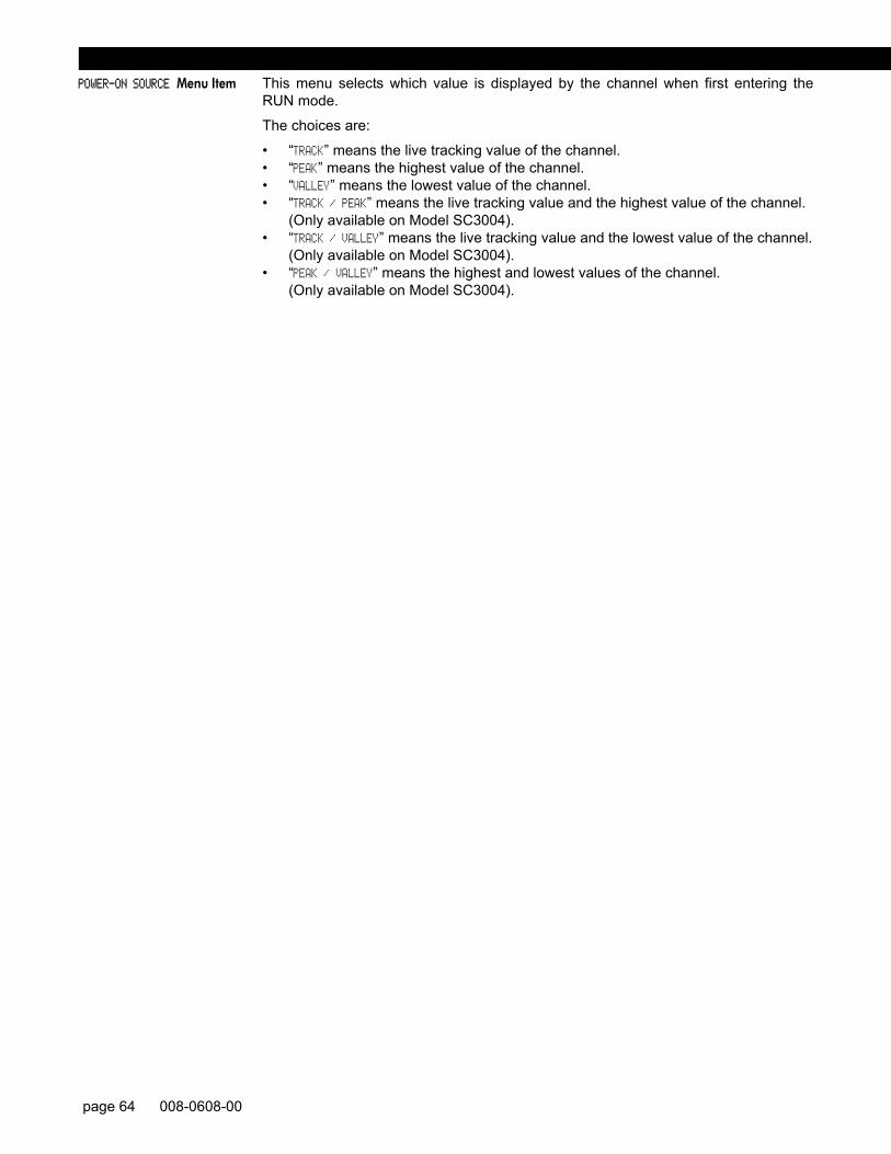
POWER-ON SOURCE Menu Item This menu selects which value is displayed by the channel when first entering theRUN mode.
The choices are:
• “TRACK” means the live tracking value of the channel. • “PEAK” means the highest value of the channel.• “VALLEY” means the lowest value of the channel.• “TRACK / PEAK” means the live tracking value and the highest value of the channel.
(Only available on Model SC3004).• “TRACK / VALLEY” means the live tracking value and the lowest value of the channel.
(Only available on Model SC3004).• “PEAK / VALLEY” means the highest and lowest values of the channel.
(Only available on Model SC3004).
page 64 008-0608-00

Strain-G
age Input Channel10
10.5.2 DISPLAY SETUP Sub-Menu
This menu controls how data values are displayed by the channel and transmittedvia serial communications.
DISPLAY. DIGITS Menu Item Selects the number of digits displayed by the channel. The choices are:
• “5 DIGIT-BIPOLAR” displays both positive and negative numbers with five full dig-its (±99999).
• “6 DIGIT-UNIPLOAR” displays positive numbers with six full digits (999999) and negative numbers with five full digits (-99999).
• “7 DIGIT UNIPOLAR” displays positive number with seven full digits (9999999) and negative numbers with six digits (-999999).
This menu item may be automatically updated by a transducer’s Signature Mod-ule.
DISPLAY. DECPT Menu Item Selects the decimal point location on the channel’s display and serial communica-tions output. Use the [UP] and [DOWN] buttons to move the decimal point to theright and left.
This menu item may be automatically updated by a transducer’s Signature Mod-ule.
DISPLAY. COUNT-BY Menu Item Determines by what value the display increments or decrements. This will makethe display less sensitive to a noisy signal. The choices are:
• “00001” • “00002” • “00005” • “00010” • “00020” • “00050” • “00100” • “00200” This menu item may be automatically updated by a transducer’s Signature Mod-ule.
DISPLAY. UNITS Menu Item Specifies the four character label that is displayed to the right of the channel’s val-ues.
When a character position is flashing press the [UP] or [DOWN] button to changethe character. Press [ENTER] to advance to the next character.
This menu item may be automatically updated by a transducer’s Signature Mod-ule.
DISPLAY. AVERAGE Menu Item Controls the speed with which the channel’s display values will update. Displayaveraging does not affect the channel’s analog output or its peak/valley detection,which will proceed at the speed selected by the ”OPERATION -> FREQ. RESPONSE” menuitem. The choices are:
• “ON” means that the display will update four times each second. The channel’s values will be averaged for 1/4 second, then displayed.
• “OFF” means that the channel’s display will update as quickly as possible.
NOTICEThis menu item doesn’t change the mathematical scaling of the channel’s val-ues; that can be changed by altering the “CALIBRATION DATA -> FULL SCALE VALUE” menu item and then performing a re-calibration.
SC Series Instruction Manual page 65

10.5.3 AUXn FUNCTION Menu Items
The AUX1 FUNCTION and AUX2 FUNCTION menu items determine what happens when theAuxiliary Function pins (labeled as “AUX1” and “AUX2”) on the channel’s connectorare activated. These pins are “activated” when they are connected to the (-)Signature(labeled as “-MEM”) pin. The choices are:
• “DISABLED” means that activating the pin does nothing.• “TRACK HOLD” means that the tracking, peak and valley values will not be updated.• “HIGH/LOW HOLD” means that the peak and valley values will not be updated.• “HIGH/LOW CLEAR” means that the peak and valley values are reset.• “TARE ON” activates the channel’s Tare function (resets it to zero).• “TARE OFF” deactivates the channel’s Tare function.As the Auxiliary Function pins are not isolated, it is recommended that a push-buttonswitch or relay is used to connect these pins to the (-)Signature pin.
page 66 008-0608-00

Strain-G
age Input Channel10
10.5.4 CALIBRATION TYPE Menu Item
This chooses the type of calibration technique to be used. There are three meth-ods that can be used to calibrate the transducer to the Input Channel. Each hasadvantages and disadvantages as described in the table below.
It is important to know your application in order to select the appropriate cali-bration type. mV/V (“millivolt-per-volt”) Calibration is recommended for mostapplications because it doesn’t require known loads and it allows easy swappingof transducers equipped with Signature Calibration. When the best possibleaccuracy is required, Known-Load Calibration is recommended.
The choices for this menu item are:
• “TYPE= SHUNT CAL” means Shunt Calibration. First, you are prompted to apply the load entered in the “ZERO SCALE VALUE” register. Next, the instrument inserts
Table 4-4: Comparison of Calibration Types
Shunt Calibration
mV/V Calibration
2-, 3-, or 5-point
Known Load Calibration
RECOMMENDED......for most applications no yes no
...when frequently swapping transducers
yes yes no
...when best possible accuracy required
no no yes
PROS and CONSRelative accuracy good better best
Requires actual, calibrated loads to be applied
no no yes
Automatically calibrates with Sig-nature Calibration transducers
yes yes no
Max. distance of transducer from instrument w/out sense wires
15’ [5m] 50’ [15m] 300’ [100m]
Max. distance of transducer from instrument with sense wires
15’ [5m] 100’ [30m] 300’ [100m]
CALIBRATION TECHNIQUEZero-scale point from... applied load applied load applied loadFull-scale point from... transducer
output when shunt resistor
applied
internal refer-ence
applied load
Linearity correction from... data stored in Signature Module (if available)
data stored in Signature Module (if available)
2-point: none3- or 5-point:applied load
SC Series Instruction Manual page 67

a known, precision resistor into the transducer circuit, which causes a predictable apparent signal. The instrument then takes a reading and adjusts itself using the “SHUNT CAL VALUE” register.
• “TYPE= MV/V CAL” means Millivolt-per-Volt Calibration. First, you are prompted to apply the load entered in the “ZERO SCALE VALUE” register. Next, the instrument takes a reading from an accurate, internal mV/V reference. The instrument then uses the “FULL SCALE MV/V” and “FULL SCALE VALUE” values in mathematical calculations to scale its tracking values.
• “TYPE= 2 POINT CAL” means 2-Point Known Load Calibration. You are prompted to apply the loads to the transducer that were entered in the “KNOWN POINT 1/2” and “KNOWN POINT 2/2” registers. This technique assumes that the transducer is linear, so the usual loads used are zero scale and full scale.
• “TYPE= 3 POINT CAL” means 3-Point Known Load Calibration. You are prompted to apply the loads to the transducer that were entered in the “KNOWN POINT 1/3” and “KNOWN POINT 2/3” and “KNOWN POINT 3/3” registers. This technique can be used to compensate for the non-linearity in the transducer. The usual loads used are zero scale, half scale and full scale, but you are not restricted to these loads.
• “TYPE= 5 POINT CAL” means 5-Point Known Load Calibration. You are prompted to apply the loads to the transducer that were entered in the “KNOWN POINT 1/5”, “KNOWN POINT 2/5”, “KNOWN POINT 3/5”, “KNOWN POINT 4/5” and “KNOWN POINT 5/5” registers. This technique can be used to compensate for the non-linearity in the transducer. The usual loads used are zero scale, one-quarter scale, half scale, three-quarters scale and full scale, but you are not restricted to these loads.
The selection of the calibration type affects what menu items appear in the CALIBRATIONDATA sub-menu.
page 68 008-0608-00

Strain-G
age Input Channel10
10.5.5 CALIBRATION DATA Sub-Menu
This enters the values that will be used by the instrument when it calibrates itselfto the transducer. The menu items that are displayed will change according towhat the CALIBRATION TYPE is set for.
EXCITATION Menu Item This sets the excitation voltage used to power up the transducer. The choice are:
• “EXCITATION=5VDC” means 5 volts DC excitation.• “EXCITATION=10VDC” means 10 volts DC excitation.This menu item may be automatically updated by a transducer’s Signature Mod-ule.
FULL SCALE MV/V Menu Item The transducer output when its full-scale load is applied to it, in milliVolts-per-Volt.This menu item is used by the instrument to set the gain of its amplifier circuit, and(when the CALIBRATION TYPE is set to mV/V Calibration) to calibrate the instrument.This value is normally found on the transducer’s Certificate of Calibration issuedby its manufacturer.
This menu item may be automatically updated by a transducer’s Signature Mod-ule. It is available for all calibration types.
FULL SCALE VALUE Menu Item The transducer’s full-scale output in engineering units.
This menu item may be automatically updated by a transducer’s Signature Mod-ule. It is available only with the Shunt Calibration and mV/V Calibration types.
ZERO SCALE VALUE Menu Item The transducer’s zero-scale output in engineering units, which is usually zero.
This menu item may be automatically updated by a transducer’s Signature Mod-ule. It is available only with the Shunt Calibration and mV/V Calibration types.
SHUNT CAL VALUE Menu Item The shunt calibration value must be calculated by using information found on thetransducer’s Certificate of Calibration and the following formula:
The terms have the following meanings:
• Shunt-Calibration Output: The transducer’s output under shunt calibration conditions in mV/V. Sometimes called “Shunt Cal. Factor”.
• Full-Scale Output: The transducer’s full-scale output in mV/V. Sometimes called “Calibration Factor”.
• Full-Scale Capacity: The transducer’s desired full-scale reading in engineer-ing units (PSI, lbs, Kg, etc.). You may wish to convert the engineering units of this value. For example, if the transducer full scale is 3000PSIG and you wish the channel to read in bar, you must convert 3000PSIG into 206.84 bar.
This menu item may be automatically updated by a transducer’s Signature Mod-ule.
The shunt resistor’s ohmic value used to generate the Shunt-Calibration Output isgiven on the transducer’s Certificate of Calibration. Normally, the instrument hasa shunt calibration resistor of 59000 (59K) ohms installed. If your transducer andinstrument were purchased at the same time from Sensotec, the correct shuntresistor has been installed.
This menu item is only available with the Shunt Calibration type.
SHUNT CAL VALUEShunt-Calibration Output
Full-Scale Output------------------------------------------------------------- Full-Scale Capacity×=
SC Series Instruction Manual page 69

Figure 10-2: Shunt Calibration Resistor Location
To verify proper transducer operation, you can apply the shunt resistor to the trans-ducer while the instrument is in the RUN mode. Press and hold the [ENTER] buttonfor three seconds; this will apply the shunt resistor and display the reading.
KNOWN POINT x/y Menu Items This enters the engineering units for the known-load calibration points. These pointsmust match the actual loads that you will apply to the instrument during calibration.The number of calibrations points depends on the CALIBRATION TYPE.
When using the 2-Point Known Load Calibration type, the following menu items areavailable:
• “KNOWN POINT 1/2”: point 1 of 2, usually 0% of the transducer’s full-scale capacity.• “KNOWN POINT 2/2”: point 2 of 2, usually 100% of the transducer’s full-scale capacity.
When using the 3-Point Known Load Calibration type, the following menu items areavailable:
• “KNOWN POINT 1/3”: point 1 of 3, usually 0% of the transducer’s full-scale capacity.• “KNOWN POINT 2/3”: point 2 of 3, usually 50% of the transducer’s full-scale capacity.• “KNOWN POINT 3/3”: point 3 of 3, usually 100% of the transducer’s full-scale capacity.
When using the 5-Point Known Load Calibration type, the following menu items areavailable:
• “KNOWN POINT 1/5”: point 1 of 5, usually 0% of the transducer’s full-scale capacity.• “KNOWN POINT 2/5”: point 2 of 5, usually 25% of the transducer’s full-scale capacity.• “KNOWN POINT 3/5”: point 3 of 5, usually 50% of the transducer’s full-scale capacity.• “KNOWN POINT 4/5”: point 4 of 5, usually 75% of the transducer’s full-scale capacity.• “KNOWN POINT 5/5”: point 5 of 5, usually 100% of the transducer’s full-scale capacity.
These menu items are only available with the Known-Load Calibration types.
NOTICETo insure both correct operation of the transducer and application of the load, the instrument expects the voltage applied at each known-load point to be increasing. For example, the load applied at Known-Load Point 2/2 must cause the transducer to produce a more positive voltage than at Known-Load Point 1/2.
page 70 008-0608-00

Strain-G
age Input Channel10
10.5.6 CALIBRATE Menu Item
This menu item performs a calibration according to what was entered in the CALI-BRATION TYPE and CALIBRATION DATA menu items.
If the CALIBRATION TYPE is Shunt Calibration...
• The display will read DOING SHUNT CAL, and prompt you to APPLY 00000 UNIT (where 00000 and UNIT are previously entered as ZERO SCALE VALUE and DISPLAY. UNITS. When you have applied this load to the transducer, press [ENTER].
• The display will then read WORKING and calibration will take place. Upon com-pletion, the display will indicate DONE and the instrument will return to the RUN mode.
If the CALIBRATION TYPE is mV/V Calibration...
• The display will read DOING MV/V CAL, and prompt you to APPLY 00000 UNIT (where 00000 and UNIT are previously entered as ZERO SCALE VALUE and DISPLAY. UNITS). When you have applied this load to the transducer, press [ENTER].
• The display will then read WORKING and calibration will take place. Upon com-pletion, the display will indicate DONE and the instrument will return to the RUN mode.
If the CALIBRATION TYPE is 2-Point Known Load Calibration...
• The display will read DOING 2POINT CAL, and prompt you to APPLY 00000 UNIT (where 00000 and UNIT are previously entered as KNOWN POINT 1/2 and DISPLAY. UNITS). When you have applied this load to the transducer, press [ENTER].
• The display will read WORKING, then APPLY 01000 UNIT (where 01000 and UNIT are previously entered as KNOWN POINT 2/2 and DISPLAY. UNITS). When you have applied this load to the transducer, press [ENTER].
• Upon completion, the display will indicate DONE and the instrument will return to the RUN mode.
If the CALIBRATION TYPE is 3-Point Known Load Calibration...
• The display will read DOING 3POINT CAL, and prompt you to APPLY 00000 UNIT (where 00000 and UNIT are previously entered as KNOWN POINT 1/3 and DISPLAY. UNITS). When you have applied this load to the transducer, press [ENTER].
• The display will read WORKING, then APPLY 00500 UNIT (where 00500 and UNIT are previously entered as KNOWN POINT 2/3 and DISPLAY. UNITS). When you have applied this load to the transducer, press [ENTER].
• The display will read WORKING, then APPLY 01000 UNIT (where 01000 and UNIT are previously entered as KNOWN POINT 3/3 and DISPLAY. UNITS). When you have
NOTICEBefore performing a calibration, the transducer must be connected to the instrument, the CALIBRATION TYPE must be selected (see “CALIBRATION TYPE Menu Item” on page 67), and the CALIBRATION DATA must be entered (see “CALI-BRATION DATA Sub-Menu” on page 69).
NOTICEFor maximum accuracy, allow at least twenty minutes of warm-up with the exci-tation voltage applied to the transducer before calibration.
SC Series Instruction Manual page 71
applied this load to the transducer, press [ENTER]. • Upon completion, the display will indicate DONE and the instrument will return to the
RUN mode.
If the CALIBRATION TYPE is 5-Point Known Load Calibration...
• The display will read DOING 5POINT CAL, and prompt you to APPLY 00000 UNIT (where 00000 and UNIT are previously entered as KNOWN POINT 1/5 and DISPLAY. UNITS). When you have applied this load to the transducer, press [ENTER].
• The display will read WORKING, then APPLY 00250 UNIT (where 00250 and UNIT are pre-viously entered as KNOWN POINT 2/5 and DISPLAY. UNITS). When you have applied this load to the transducer, press [ENTER].
• The display will read WORKING, then APPLY 00500 UNIT (where 00500 and UNIT are pre-viously entered as KNOWN POINT 3/5 and DISPLAY. UNITS). When you have applied this load to the transducer, press [ENTER].
• The display will read WORKING, then APPLY 00750 UNIT (where 00750 and UNIT are pre-viously entered as KNOWN POINT 4/5 and DISPLAY. UNITS). When you have applied this load to the transducer, press [ENTER].
• The display will read WORKING, then APPLY 01000 UNIT (where 01000 and UNIT are pre-viously entered as KNOWN POINT 5/5 and DISPLAY. UNITS). When you have applied this load to the transducer, press [ENTER].
• The display will now read RETURN PNTS.=NO. If you press [ENTER], the display will indicate DONE and the instrument will return to the RUN mode. If you use the [UP] button and [ENTER] to select RETURN POINTS=YES, you may now apply the same loads again but in reverse order. This will allow the instrument to measure and partially eliminate any hysteresis that may be present in the transducer. After the loads have been applied again, the display will indicate DONE and the instrument will return to the RUN mode.
page 72 008-0608-00
Strain-G
age Input Channel10
10.5.7 DAC SETUP Sub-Menu This sub-menu contains four items that control the Digital-to-Analog Converter(DAC) output of the channel.
DAC. CHANNEL Menu Item This chooses which channel will drive the DAC output. Normally, the DAC locatedon a particular channel will be driven by that channel, but that need not be thecase. For example, if several channels were assigned to load cells on a weighingplatform, the sum of all channels could (mathematically) drive one channel’s DACoutput.
If the DAC is set-up to be driven by its own channel’s tracking value, the AnalogOutput will have the frequency response specified by the channel’s FREQ. RESPONSEmenu item. Otherwise, the Analog Output will operate more slowly.
DAC. SOURCE Menu Item This designates the data source of the channel monitored by the analog output.
The options for this menu item are:
• “TRACK” means the live tracking value of the channel. • “PEAK” means the highest value of the channel since the peak/valley detector
was last cleared.• “VALLEY” means the lowest value of the channel since the peak/valley detector
was last cleared.If the DAC is set-up to be driven by its own channel’s tracking value, the AnalogOutput will have the frequency response specified by the channel’s FREQ. RESPONSEmenu item. Otherwise, the Analog Output will operate more slowly.
DAC. ZERO-SCALE Menu Item This specifies what value, in engineering units, corresponds to zero output on theAnalog Output.
“Zero output” might be 0 Volts, 2.5 Volts, 5 Volts, 4 mA or 12 mA depending on ifthe channel has a voltage or current output and how it is configured. See “AnalogOutput Configuration” on page 76 the for details.
If the UPDATE DAC SETUP menu item is set to “ON” and the DAC. CHANNEL menu item isset to this channel, this menu item may be automatically updated by a trans-ducer’s Signature Module. If the UPDATE DAC SETUP menu item is “OFF”, a trans-ducer’s Signature Module will not change this menu item.
DAC. FULL-SCALE Menu Item Specifies what value, in engineering units, corresponds to full output on the Ana-log Output.
“Full output” might be 5 Volts, 10 Volts or 20 mA depending on if the channel hasa voltage or current output and how it is configured. See “Analog Output Configu-ration” on page 76 for details.
If the UPDATE DAC SETUP menu item is set to “ON” and the DAC. CHANNEL menu item isset to this channel, this menu item may be automatically updated by a trans-ducer’s Signature Module. If the UPDATE DAC SETUP menu item is “OFF”, a trans-ducer’s Signature Module will not change this menu item.
SC Series Instruction Manual page 73

10.5.8 SIGNATURE MODULE Sub-Menu
UPDATE SIG.MOD? Menu Item Updates the information stored in the transducer’s Signature Module with any newsettings that is entered into the instrument with the SETUP menus. The settings thatwill be updated are:
• EXCITATION • FULL SCALE MV/V• FULL SCALE VALUE• SHUNT CAL VALUE• DISPLAY. UNITSNote that changes made to the instruments display setup (such as decimal point andcount-by settings) are not updated into the Signature Module.
Updating enters these new settings from the instrument into the Signature Module. Ifyou do not update the Signature Module, connect a different transducer to the instru-ment and then re-connect the original transducer again, the instrument will revert tothe settings that are stored inside the Signature Module.
The options for this menu item are:
• “NO” will not update the Signature Module.• “YES” will display WORKING, update the Signature Module, then display DONE.
DEFAULT SIG.MOD? Menu Item This menu item will overwrite any user settings in the Signature Module with the origi-nal default settings. The Signature Module always maintains a copy of the originaldefault settings that were created at the factory.
The options for this menu item are:
• “NO” will not restore original default settings.• “YES” will display WORKING, update the Signature Module, with the original factory set-
tings, then display DONE.
UPDATE DAC SETUP Menu Item This menu item determines whether or not the DAC. FULL SCALE and DAC. ZERO SCALE Ana-log Output settings are overwritten with information from a Signature Module when anew transducer is detected by the instrument.
The options for this menu item are:
• “YES” will allow a newly detected Signature Module to update the Analog Output settings.
• “NO” will not allow automatic updating of the Analog Output settings.
page 74 008-0608-00

Strain-G
age Input Channel10
10.5.9 DIAGNOSTICS Sub-Menu
DAC FULL SCALE Menu Item When this menu item is selected, the Analog Output of the channel is forced to itsfull-scale output, then DAC UPDATED is displayed. This is useful when calibrating ortrimming the readout connected to the Analog Output.
DAC ZERO SCALE Menu Item When this menu item is selected, the Analog Output of the channel is forced to itszero-scale output, then DAC UPDATED is displayed. This is useful when calibrating ortrimming the readout connected to the Analog Output.
VERSION INFO Menu Item This menu item displays the part number and revision level of the firmware usedby this channels microprocessor.
DISPLAY ADC Menu Item The options for this menu item are:
• “OFF” will allow the [VALUE] button to cycle through “TK” (tracking value), “HI” (peak value) and “LO” (valley value). This is the recommended option.
• “ON” will allow the “AD” (percentage of the Analog-to-Digital converter’s full-scale digitizing capability) display source to be available along with “TK” (track-ing value), “HI” (peak value) and “LO” (valley value) when the [VALUE] button is pressed on the front panel.
The Analog-to-Digital converter counts are displayed as a percentage from-100.00% to 100.00%.
This can be used to verify that the transducer’s output does not exceed the inputrange of the instrument. If the Analog-to-Digital converter readings display morethan +/-10% when there is no load on the transducer, the transducer has a highzero offset.
LINEARIZATION Menu Item The options for this menu item are:
• “ON” will allow linearization data obtained from either the Signature Module or a 3-Point or 5-Point Known Load Calibration to affect a channel’s scaled values. This is the recommended option.
• “OFF” will not allow linearization data to effect the channel’s scaled values. This is useful when diagnosing problems in a calibration procedure.
DISABLE CHANNEL Menu Item The options for this menu item are:
• “ON” will bypass the INITIALIZE and RUN modes of the channel. The track, peak and valley values of the channel are forced to 0. This option is helpful when a channel is installed but not being used. ERROR 46, which will nor-mally occur when the (+)Sense and (-)Sense wires are not connected prop-erly, will be surpressed.
• “OFF” will allow normal operation of the channel.
SC Series Instruction Manual page 75

10.6 Analog Output Configuration
10.6.1 Identifying the Output Type
A Strain-Gage Input channel is available with one of two types of digital-to-analog(DAC) outputs: voltage or current. You can determine which type of output achannel has by one of three ways:
• Consulting the instrument’s Customer Information Sheet• Examining the SYSTEM MENU -> CONFIGURATION -> CHANNEL nn TYPE menu item where
nn is the number of the channel. If the channel’s type is STRAIN GAGE V, it has a voltage output. If the channel’s type is STRAIN GAGE I, it has a current output.
• Examining the channel’s circuit board as shown in the figure below.
10.6.2 Channel Menu Items The Analog Output can be driven by any channel’s track, peak or valley value.
See the “Channel Menu” section earlier in this chapter for a complete listing ofSETUP menu items available on the DAC. SETUP sub-menu.
10.6.3 Output Selection Jumpers located on the channel’s circuit board determine what outputs are gener-ated when the value selected to drive the Analog Output (from the DAC. CHANNEL andDAC. SOURCE menu items) equals the DAC. FULL SCALE and DAC. ZERO SCALE settings.
Figure 10-3: Digital-to-Analog Output Jumper Locations
DAC. ZERO SCALE
OutputDAC. FULL SCALE
OutputJ30
jumperJ31
jumper
CHANNELS WITH VOLTAGE OUPUT0-5V 2.5 Volts 5 Volts open closed±5V 0 Volts 5 Volts open open
0-10V 5 Volts 10 Volts closed closed±10V 0 Volts 10 Volts closed open
CHANNELS WITH CURRENT OUTPUT4-20mA 4 mA 20 mA open open4-20mA 12 mA 20 mA open closed
page 76 008-0608-00

Strain-G
age Input Channel10
10.7 Troubleshooting
10.7.1 Error Messages See “Error Messages” on page 151 for information relating to error messages.
10.7.2 Common Problems and Solutions
Erratic Display Check electrical connections for continuity and the transducer’s wiring code fromits Certificate of Calibration.
Make sure that the load on the transducer is constant.
Check millivolt input to the (+)Signal (“+SIG”) and (-)Signal (“-SIG”) pins with avoltmeter.
+OVLD or -OVLD on Display Indicates that the voltage across the (+)Signal (“+SIG”) and (-)Signal (“-SIG”) pinsis overranging or underranging the amplifier circuit. Make certain all wires areconnected properly.
If you remove all load from the transducer and you still see this message, the(+)Excitation (“+EXC”) or (-)Excitation (“-EXC”) pins may be shorted to the (+)Sig-nal (“+SIG”) or (-)Signal (“-SIG”) pins.
If you remove all load from the transducer and you get a numeric reading, thetransducer may have a high zero offset. Use the channel’s SETUP menu and setDIAGNOSTICS -> DISPLAY ADC to “ON”; in the RUN mode this will allow the [VALUE] but-ton to display raw A/D readings as a percentage of its full-scale. If the raw A/Dreadings display more than +/-10% when there is no load on the transducer, thetransducer has a high zero offset.
Analog Output Incorrect Make certain of the type of Analog Output (voltage or current) that the channel isequipped with; see “Identifying the Output Type” on page 76.
Use the DIAGNOSTICS -> DAC FULL SCALE and DIAGNOSTICS -> DAC ZERO SCALE menu items toforce the Analog Output to a known output. Then, adjust your readout device,panel meter, PLC or data acquisition system to match.
Check the output selection jumpers; see “Output Selection” on page 76.
“APPLY 00000” on Power-up The channel has detected that the transducer connected to the instrument is dif-ferent than the one the channel was last calibrated with. Because the CALIBRATIONTYPE is set to either Shunt Calibration or mV/V Calibration, the instrument isprompting you to apply zero load in order to auto-calibrate to this new transducer.
Do one of the following, depending on the situation:
• Re-connect the original transducer to the channel and re-start the instrument.• Press [ENTER] to re-calibrate the channel to this new transducer using Shunt
or mV/V Calibration and accept the presently applied load as “0”. (In situa-tions where one can’t apply “0” load to an absolute pressure transducer or a load cell with a pre-load, you can change the CALIBRATION DATA -> ZERO-SCALE VALUE menu item from “0” to a load that can be applied. For example, 14.7 PSIA or the known pre-load on the load cell.
• Use the CALIBRATE menu item to perform a Known-Load Calibration with this new transducer.
Auxiliary Function Pins Not Operating
Make sure that the AUX1 FUNCTION or AUX2 FUNCTION SETUP menu items are set cor-rectly; if they are set to DISABLED then they will not operate.
The Auxiliary Function (“AUX1” and “AUX2”) pins must be connected to pin 10,
SC Series Instruction Manual page 77

not pin 8, to activate them.
Sensitivity to EMI/RFI To obtain maximum immunity to electromagnetic or radio frequency interference,make certain that the shields of the transducer cables are connected to the “cableshield connection screw” on the rear panel of the instrument. See “UnamplifiedTransducer Connection to Strain-Gage Input Channel” on page 60, “ExternalArrangement of AC powered SC1000 and SC2000” on page 27 and “ExternalArrangement of Model SC3004” on page 33.
Shunt Calibration Feature not Operating
To activate the channel’s shunt calibration function while the instrument is in RUNMode, see “Shunt Calibration Check” on page 21. This serves as a quick check ofthe shunt cal feature.
page 78 008-0608-00

AC/AC-LVDT Input Channel
11
Chapter 11AC/AC-LVDT Input Channel
11.1 Features
The AC/AC-LVDT Input channel provides an AC excitation voltage to and acceptsAC signals from LVDT (Linear Variable Differential Transformer) transducers.These signals are digitized, converted into engineering units, and placed into thetrack, peak and valley data values of the channel. Setup and calibration of thechannel are made manually through the SETUP mode.
The analog-to-digital converter features adjustable digital, low-pass filtering, 12- to18-bit resolution (depending on the filter setting) and has several different inputranges. These many input ranges allow ±25,000 count resolution (at the slowestfilter setting) for a wide variety of LVDT outputs.
The AC/AC-LVDT Input channel is calibrated to the transducer by using known-displacement calibration.
Two rear panel control inputs can be field-configured for such functions as remotetare, disabling peak/valley detection and clearing the peak/valley values. A stan-dard voltage or optional current digital-to-analog output is also provided.
NOTICETo use a DC/DC LVDT with an SC instrument, use a High-Level Input channel instead of an AC/AC-LVDT Input channel.
SC Series Instruction Manual page 79

11.2 Wiring
Connect your transducer to an AC/AC-LVDT Input channel by wiring it to the 12-pinconnector of that channel. The Customer Information Sheet that shipped with theinstrument describes which cards are installed in each channel. The pin-out for thisconnector is shown on the following table.
The Analog Output and Analog Return pins are electrically isolated from all other pinson the instrument.
Figure 11-1: Connection of Four- or Five-wire AC/AC-LVDT
Table 5-5: AC/AC-LVDT Input Channel Pin Connections
Pin Label Function Reference Pin
1 (top) +EXC (+)Excitation 102 N/C No connection3 N/C No connection4 -EXC (-)Excitation 105 +SIG (+)Signal 106 -SIG (-)Signal 107 +OUT Analog Output 88 -OUT Analog Return -9 N/C No connection
10 DGND Digital Ground -11 AUX1 Auxiliary Function 1
(connect to pin 10 to activate)10
12(bottom)
AUX2 Auxiliary Function 2 (connect to pin 10 to activate)
10
page 80 008-0608-00

AC/AC-LVDT Input Channel
11
11.3 Calibration Procedure
If you are not familiar with operating the instrument in the SETUP menu mode,see “SETUP Menu mode” on page 23. A listing of all menu items is given in“Setup Menu Reference” on page 157.
Step 1: Wire the transducer to the channel’s connector.See “Wiring” on page 80 for details.
Step 2: Enter the CALIBRATION TYPE. You must have the capability to apply either two, three, or five known dis-placements to the transducer. The CALIBRATION TYPE menu item allows you tospecify how many known displacements will be applied during calibration.
Step 3: Enter the CALIBRATION DATA.Consult the Certificate of Calibration for the transducer when entering infor-mation in the CALIBRATION DATA sub-menu.
Step 4: Determine the LVDT’s electrical null point, then physically mount it.The electrical null is the armature position that produces the least electricaloutput. Once this point has been determined, the transducer is physicallyclamped into position. See “Electrical Null and Transducer Mounting” onpage 93.
Step 5: Perform the calibration.Using the CALIBRATE menu item starts the calibration process. You will beprompted to apply displacements to the transducer as required.
SC Series Instruction Manual page 81

11.4 Specifications
TRANSDUCER INPUTTransducer type full-bridge, AC/AC-LVDT
Excitation Voltage 3 VRMS @ 5kHz,short circuit protected
Transducer full-scale output .1 to 15 VRMS @ 3 VRMS excitationAmplifier Gain Selection automatic
Calibration Type 2-, 3- or 5- point known displacementA/D Converter 24-bit Sigma-DeltaLow-pass filter digital, 24-tap FIR
Resolution see page 83Frequency Response see page 83
AUXILLIARY INPUTSQuantity 2
Type momentary contact closureResponse Time < 5ms
Field-Selectable Functions tare on, tare off,peak/valley clear, peak/valley hold,
track hold
ANALOG OUTPUTVoltage range (voltage output
channels)5, ±5, 10 or ±10 VDC
Current range (current outputchannels)
4-20 mA
Source any channel’s track, peak or valley valueIsolation 500V
Resolution 13 bitsFrequency Response same as input if driven by the same chan-
nel’s tracking data
page 82 008-0608-00

AC/AC-LVDT Input Channel
11
11.5 Channel Menu
Each AC/AC-LVDT Input channel is configured and calibrated via its channelmenu. Detailed instructions on operating the instrument in the SETUP Menumode can be found in “SETUP Menu mode” on page 23. A diagram of all menusis located in “Setup Menu Reference” on page 157.
11.5.1 OPERATION Sub-Menu
This menu controls the operation of this channel when the instrument is in theRUN mode.
AUTO-ZERO Menu Item This enables or disables the channel’s automatic zeroing function. Whenenabled, the channel will reset its tracking value to zero when the tracking value isless than 10 display counts for a period of 10 seconds. This removes the effect ofslight temperature shifts in the transducer’s output.
The two options for this menu item are “ON” and “OFF”.
FREQ. RESPONSE Menu Item This sets the frequency response, step response, and resolution of the channelaccording to the table below. The tracking value, peak/valley detector values andanalog output on this channel are all affected. The default value of 016. HERTZ issuitable for most applications.
NOTICETo compensate for the transducer’s initial warm-up shift, the auto-zero function operates every 2 seconds during the first 60 seconds of RUN mode operation.
Frequency Response
Step Response (ms) (typical)
Resolution (counts) (not including minimum 10%
overrange/underrange capability)002. HERTZ/FAST 40 ±25000
002. HERTZ 440 ±25000008. HERTZ 110 ±15000016. HERTZ 55 ±10000032. HERTZ 28 ±10000050. HERTZ 16 ±5000100. HERTZ 8 ±5000250. HERTZ 3 ±2000500. HERTZ 2 ±2000800. HERTZ 2 ±2000
NOTICEYour particular LVDT may have a lower frequency response than the AC-AC LVDT Input channel.
SC Series Instruction Manual page 83

POWER-ON SOURCE Menu Item This menu selects which value is displayed by the channel when first entering theRUN mode.
The choices are:
• “TRACK” means the live tracking value of the channel. • “PEAK” means the highest value of the channel.• “VALLEY” means the lowest value of the channel.• “TRACK / PEAK” means the live tracking value and the highest value of the channel.
(Only available on Model SC3004).• “TRACK / VALLEY” means the live tracking value and the lowest value of the channel.
(Only available on Model SC3004).• “PEAK / VALLEY” means the highest and lowest values of the channel.
(Only available on Model SC3004).
page 84 008-0608-00

AC/AC-LVDT Input Channel
11
11.5.2 DISPLAY SETUP Sub-Menu
This menu controls how data values are displayed by the channel and transmittedvia serial communications.
DISPLAY. DIGITS Menu Item Selects the number of digits displayed by the channel. The choices are:
• “5 DIGIT-BIPOLAR” displays both positive and negative numbers with five full dig-its (±99999).
• “6 DIGIT-UNIPLOAR” displays positive numbers with six full digits (999999) and negative numbers with five full digits (-99999).
• “7 DIGIT UNIPOLAR” displays positive number with seven full digits (9999999) and negative numbers with six digits (-999999).
DISPLAY. DECPT Menu Item Selects the decimal point location on the channel’s display and serial communica-tions output. Use the [UP] and [DOWN] buttons to move the decimal point to theright and left.
DISPLAY. COUNT-BY Menu Item Determines by what value the display increments or decrements. This will makethe display less sensitive to a noisy signal. The choices are:
• “00001” • “00002” • “00005” • “00010” • “00020” • “00050” • “00100” • “00200”
DISPLAY. UNITS Menu Item Specifies the four character label that is displayed to the right of the channel’s val-ues.
When a character position is flashing press the [UP] or [DOWN] button to changethe character. Press [ENTER] to advance to the next character.
DISPLAY. AVERAGE Menu Item Controls the speed with which the channel’s display values will update. Displayaveraging does not affect the channel’s analog output or its peak/valley detection,which will proceed at the speed selected by the ”OPERATION -> FREQ. RESPONSE” menuitem. The choices are:
• “ON” means that the display will update four times each second. The channel’s values will be averaged for 1/4 second, then displayed.
• “OFF” means that the channel’s display will update as quickly as possible.
11.5.3 AUXn FUNCTION Menu Items
The AUX1 FUNCTION and AUX2 FUNCTION menu items determine what happens when theAuxiliary Function pins (labeled as “AUX1” and “AUX2”) on the channel’s connec-tor are activated. These pins are “activated” when they are connected to theDGND pin. The choices are:
• “DISABLED” means that activating the pin does nothing.• “TRACK HOLD” means that the tracking, peak and valley values will not be
NOTICEThis menu item doesn’t change the mathematical scaling of the channel’s val-ues; that can be changed by altering the “CALIBRATION DATA -> KNOWN POINT X/Y” menu items and then performing a re-calibration.
SC Series Instruction Manual page 85

updated.• “HIGH/LOW HOLD” means that the peak and valley values will not be updated.• “HIGH/LOW CLEAR” means that the peak and valley values are reset. • “TARE ON” activates the channel’s Tare function (resets it to zero).• “TARE OFF” deactivates the channel’s Tare function.As the Auxiliary Function pins are not isolated, it is recommended that a push-buttonswitch or relay is used to connect these pins to the DGND pin.
page 86 008-0608-00

AC/AC-LVDT Input Channel
11
11.5.4 CALIBRATION TYPE Menu Item
The choices for this menu item are:
• “TYPE= 2 POINT CAL” means 2-Point Known Displacement Calibration. You are prompted to apply the displacements to the transducer that were entered in the “KNOWN POINT 1/2” and “KNOWN POINT 2/2” registers. This technique assumes that the transducer is linear throughout the entire stroke, so the usual dis-placements used are zero scale and full scale.
• “TYPE= 3 POINT CAL” means 3-Point Known Displacement Calibration. You are prompted to apply the displacements to the transducer that were entered in the “KNOWN POINT 1/3” and “KNOWN POINT 2/3” and “KNOWN POINT 3/3” registers. This technique can be used to compensate for the different sensitivities that an LVDT may have on each side of its electrical null. The usual displacements used are zero scale, half scale and full scale, but you are not restricted to these displacements.
• “TYPE= 5 POINT CAL” means 5-Point Known Displacement Calibration. You are prompted to apply the displacements to the transducer that were entered in the “KNOWN POINT 1/5”, “KNOWN POINT 2/5”, “KNOWN POINT 3/5”, “KNOWN POINT 4/5” and “KNOWN POINT 5/5” registers. This technique can be used to compensate for the non-linearity in the transducer as well as the different sensitivities on each side of its electrical null. The usual displacements used are zero scale, one-quarter scale, half scale, three-quarters scale and full scale, but you are not restricted to these displacements.
The selection of the calibration type affects what menu items appear in the CALI-BRATION DATA sub-menu.
SC Series Instruction Manual page 87

11.5.5 CALIBRATION DATA Sub-Menu
This sub-menu enters the values that will be used by the instrument when it calibratesitself to the transducer. The menu items that are displayed will change according towhat the CALIBRATION TYPE is set for.
FULL SCALE VRMS Menu Item The transducer output when its full-scale displacement is applied to it, in Volts RMS(root-mean-squared) assuming 3 VRMS excitation. This menu item is used by theinstrument to set gain of its amplifier circuit. This value is normally found on the trans-ducer’s Certificate of Calibration issued by its manufacturer.
KNOWN POINT x/y Menu Items This enters the engineering units for the known-displacement calibration points.These points must match the actually displacements that you will apply to the trans-ducer during calibration. The number of calibrations points depends on the CALIBRATIONTYPE.
When using the 2-Point Known Displacement Calibration type, the following menuitems are available:
• “KNOWN POINT 1/2”: point 1 of 2, usually 0% of the transducer’s full-scale capacity.• “KNOWN POINT 2/2”: point 2 of 2, usually 100% of the transducer’s full-scale capacity.
When using the 3-Point Known Displacement Calibration type, the following menuitems are available:
• “KNOWN POINT 1/3”: point 1 of 3, usually 0% of the transducer’s full-scale capacity.• “KNOWN POINT 2/3”: point 2 of 3, usually 50% of the transducer’s full-scale capacity.• “KNOWN POINT 3/3”: point 3 of 3, usually 100% of the transducer’s full-scale capacity.
When using the 5-Point Known Displacement Calibration type, the following menuitems are available:
• “KNOWN POINT 1/5”: point 1 of 5, usually 0% of the transducer’s full-scale capacity.• “KNOWN POINT 2/5”: point 2 of 5, usually 25% of the transducer’s full-scale capacity.• “KNOWN POINT 3/5”: point 3 of 5, usually 50% of the transducer’s full-scale capacity.• “KNOWN POINT 4/5”: point 4 of 5, usually 75% of the transducer’s full-scale capacity.• “KNOWN POINT 5/5”: point 5 of 5, usually 100% of the transducer’s full-scale capacity.
NOTICETo insure both correct operation of the transducer and application of the dis-placement, the instrument expects the voltage applied at each known-displace-ment point to be increasing. For example, the displacement applied at Known-Displacement Point 2/2 must cause the transducer to produce a more positive voltage than at Known-Displacement Point 1/2. You may need to swap the (+)Signal and (-)Signal wires on the 12-pin channel connector to accomplish this.
page 88 008-0608-00

AC/AC-LVDT Input Channel
11
11.5.6 CALIBRATE Menu Item
This menu item performs a calibration according to what was entered in the CALI-BRATION TYPE and CALIBRATION DATA menu items.
If the CALIBRATION TYPE is 2-Point Known Displacement Calibration...
• The display will read DOING 2POINT CAL, and prompt you to APPLY 00000 UNIT (where 00000 and UNIT are previously entered as KNOWN POINT 1/2 and DISPLAY. UNITS). When you have applied this displacement to the transducer, press [ENTER].
• The display will read WORKING, then APPLY 01000 UNIT (where 01000 and UNIT are previously entered as KNOWN POINT 2/2 and DISPLAY. UNITS). When you have applied this displacement to the transducer, press [ENTER].
• Upon completion, the display will indicate DONE and the instrument will return to the RUN mode.
If the CALIBRATION TYPE is 3-Point Known Displacement Calibration...
• The display will read DOING 3POINT CAL, and prompt you to APPLY 00000 UNIT (where 00000 and UNIT are previously entered as KNOWN POINT 1/3 and DISPLAY. UNITS). When you have applied this displacement to the transducer, press [ENTER].
• The display will read WORKING, then APPLY 00500 UNIT (where 00500 and UNIT are previously entered as KNOWN POINT 2/3 and DISPLAY. UNITS). When you have applied this displacement to the transducer, press [ENTER].
• The display will read WORKING, then APPLY 01000 UNIT (where 01000 and UNIT are previously entered as KNOWN POINT 2/3 and DISPLAY. UNITS). When you have applied this displacement to the transducer, press [ENTER].
• Upon completion, the display will indicate DONE and the instrument will return to the RUN mode.
If the CALIBRATION TYPE is 5-Point Known Displacement Calibration...
• The display will read DOING 5POINT CAL, and prompt you to APPLY 00000 UNIT (where 00000 and UNIT are previously entered as KNOWN POINT 1/5 and DISPLAY. UNITS). When you have applied this displacement to the transducer, press [ENTER].
• The display will read WORKING, then APPLY 00250 UNIT (where 00250 and UNIT are previously entered as KNOWN POINT 2/5 and DISPLAY. UNITS). When you have applied this displacement to the transducer, press [ENTER].
• The display will read WORKING, then APPLY 00500 UNIT (where 00500 and UNIT are
NOTICEBefore performing a calibration, the transducer must be connected to the instrument, the CALIBRATION TYPE must be selected (see “CALIBRATION TYPE Menu Item” on page 87) and the CALIBRA-TION DATA must be entered (see “CALIBRATION DATA Sub-Menu” on page 88).
NOTICEFor maximum accuracy, allow at least twenty minutes of warm-up with the exci-tation voltage applied to the transducer before calibration.
SC Series Instruction Manual page 89

previously entered as KNOWN POINT 3/5 and DISPLAY. UNITS). When you have applied this displacement to the transducer, press [ENTER].
• The display will read WORKING, then APPLY 00750 UNIT (where 00750 and UNIT are pre-viously entered as KNOWN POINT 4/5 and DISPLAY. UNITS). When you have applied this displacement to the transducer, press [ENTER].
• The display will read WORKING, then APPLY 01000 UNIT (where 01000 and UNIT are pre-viously entered as KNOWN POINT 5/5 and DISPLAY. UNITS). When you have applied this displacement to the transducer, press [ENTER].
• Upon completion, the display will indicate DONE and the instrument will return to the RUN mode.
page 90 008-0608-00

AC/AC-LVDT Input Channel
11
11.5.7 DAC SETUP Sub-Menu This sub-menu contains four items that control the Digital-to-Analog (DAC) outputof the channel.
DAC. CHANNEL Menu Item This chooses which channel will drive the DAC output. Normally, the DAC locatedon a particular channel will be driven by that channel, but that need not be thecase. For example, if several channels were assigned to various transducers in asystem, the sum of all channels could (mathematically) drive one channel’s DACoutput.
If the DAC is set-up to be driven by its own channel’s tracking value, the AnalogOutput will have the frequency response specified by the channel’s FREQ. RESPONSEmenu item. Otherwise, the Analog Output will operate more slowly.
DAC. SOURCE Menu Item This designates the data source of the channel monitored by the analog output.Each channel has three data sources: the live tracking value (TRACK), its highestvalue (PEAK), and its lowest value (VALLEY).
The options for this menu item are:
• “TRACK” means the live tracking value of the channel. • “PEAK” means the highest value of the channel since the peak/valley detector
was last cleared.• “VALLEY” means the lowest value of the channel since the peak/valley detector
was last cleared.If the DAC is set-up to be driven by its own channel’s tracking value, the AnalogOutput will have the frequency response specified by the channel’s FREQ. RESPONSEmenu item. Otherwise, the Analog Output will operate more slowly.
DAC. ZERO-SCALE Menu Item This specifies what value, in engineering units, corresponds to zero output on theAnalog Output.
“Zero output” might be 0 Volts, 2.5 Volts, 5 Volts, 4 mA or 12 mA depending on ifthe channel has a voltage or current output and how it is configured. See “AnalogOutput Configuration” on page 94 for details.
DAC. FULL-SCALE Menu Item This specifies what value, in engineering units, corresponds to full output on theAnalog Output.
“Full output” might be 5 Volts, 10 Volts or 20 mA depending on if the channel hasa voltage or current output and how it is configured. See “Analog Output Configu-ration” on page 94 for details.
SC Series Instruction Manual page 91

11.5.8 DIAGNOSTICS Sub-Menu
DAC FULL SCALE Menu Item When this menu item is selected, the Analog Output of the channel is forced to its full-scale output, then DAC UPDATED is displayed. This is useful when calibrating or trimmingthe readout connected to the Analog Output.
DAC ZERO SCALE Menu Item When this menu item is selected, the Analog Output of the channel is forced to itszero-scale output, then DAC UPDATED is displayed. This is useful when calibrating or trim-ming the readout connected to the Analog Output.
VERSION INFO Menu Item This menu item displays the part number and revision level of the firmware used bythis channels microprocessor.
DISPLAY ADC Menu Item The options for this menu item are:
• “OFF” will allow the [VALUE] button to cycle through “TK” (tracking value), “HI” (peak value) and “LO” (valley value). This is the recommended option.
• “ON” will allow the “AD” (percentage of the Analog-to-Digital converter’s full-scale digitizing capability) display source to be available along with “TK” (tracking value), “HI” (peak value) and “LO” (valley value) when the [VALUE] button is pressed on the front panel.
The Analog-to-Digital converter counts are displayed as a percentage from -100.00%to 100.00%.
This can be used to establish the transducer’s electrical null prior to mounting. See“Electrical Null and Transducer Mounting” on page 93 for this procedure.
LINEARIZATION Menu Item The options for this menu item are:
• “ON” will allow linearization data obtained from a 3-Point or 5-Point Known Dis-placement Calibration to affect a channel’s scaled values. This is the recom-mended option.
• “OFF” will not allow linearization data to effect the channel’s scaled values.
DISABLE CHANNEL Menu Item The options for this menu item are:
• “ON” will bypass the INITIALIZE and RUN modes of the channel. The track, peak and valley values of the channel are forced to 0.
• “OFF” will allow normal operation of the channel.
page 92 008-0608-00

AC/AC-LVDT Input Channel
11
11.6 Electrical Null and Transducer Mounting
11.6.1 Overview The mechanical travel of an LVDT transducer is not the same as its usable mea-suring range. All LVDTs exhibit some non-linearity near the ends of its armature’smechanical travel. To insure that the LVDT will be used in its linear measuringrange, its electrical null point must be determined. This electrical null point is thearmature position which produces the minimal electrical signal output. After elec-trical null has been established, the LVDT is clamped down into final position in itsmounting fixture.
As long as the LVDT remains clamped in this position, you do not need to re-establish the electrical null prior to every calibration.
11.6.2 Procedure Step 1: Use the channel’s SETUP menu and set DIAGNOSTICS -> DISPLAY ADC to “ON”.Exit the SETUP menu and re-start the instrument.
Step 2: Display the channel to which the LVDT is connected. Press and releasethe [VALUE] button until the “AD” display source is shown. This is the rawanalog-to-digital converter readings displayed as a percentage of its full-scale (-100% to +100%).
Step 3: Move the LVDT’s armature to the position which displays the lowest valueof raw analog-to-digital converter readings (i.e. a number close to 00.000%.This is the LVDT’s electrical null.
Step 4: Firmly clamp down the LVDT’s body.
Step 5: Move the LVDT’s armature to roughly the position you wish to define as“positive full scale”. If the displayed analog-to-digital converter reading is anegative value, you must swap the wires connected to the (+)Signal and(-)Signal pins (labeled as “+SIG” and “-SIG”) on the channel’s 12-pin con-nector to make the reading positive.
SC Series Instruction Manual page 93

11.7 Analog Output Configuration
11.7.1 Identifying the Output Type
An AC/AC-LVDT Input channel is available with one of two types of digital-to-analog(DAC) outputs: voltage or current. You can determine which type of output a channelhas by one of three ways:
• Consulting the instrument’s Customer Information Sheet• Examining the SYSTEM MENU -> CONFIGURATION -> CHANNEL nn TYPE menu item where nn is
the number of the channel. If the channel’s type is AC-AC LVDT V, it has a voltage output. If the channel’s type is AC-AC LVDT I, it has a current output.
• Examining the channel’s circuit board as shown in the figure below.
11.7.2 Channel Menu Items
The Analog Output can be driven by any channel’s track, peak or valley value.
See the “Channel Menu” section earlier in this chapter for a complete listing of SETUPmenu items available on the DAC. SETUP sub-menu.
11.7.3 Output Selection Jumpers located on the channel’s circuit board determine what outputs are generatedwhen the value selected to drive the Analog Output (from the DAC. CHANNEL and DAC.SOURCE menu items) equals the DAC. FULL SCALE and DAC. ZERO SCALE settings.
Figure 11-2: Digital-to-Analog Output Jumper Locations
DAC. ZERO SCALE
OutputDAC. FULL SCALE
OutputJ30
jumperJ31
jumper
CHANNELS WITH VOLTAGE OUPUT0-5V 2.5 Volts 5 Volts open closed±5V 0 Volts 5 Volts open open
0-10V 5 Volts 10 Volts closed closed±10V 0 Volts 10 Volts closed open
CHANNELS WITH CURRENT OUTPUT4-20mA 4 mA 20 mA open open4-20mA 12 mA 20 mA open closed
page 94 008-0608-00

AC/AC-LVDT Input Channel
11
11.8 Troubleshooting
11.8.1 Error Messages See “Error Messages” on page 151 for information relating to error messages.
11.8.2 Common Problems and Solutions
Erratic Display Check electrical connections for continuity and the transducer’s wiring code from itsCertificate of Calibration.
Make sure that the displacement on the transducer is constant.
Check the input to the (+)Signal (“+SIG”) and (-)Signal (“-SIG”) pins with an RMS volt-meter in its “AC Voltage” mode. Using a voltmeter in its DC Voltage mode will alwaysdisplay 0.
+OVLD or -OVLD on Display Indicates that the voltage across the (+)Signal (“+SIG”) and (-)Signal (“-SIG”) pins isoverranging or underranging the amplifier circuit. Make certain all wires are con-nected properly, the “CALIBRATION DATA -> FULL SCALE VRMS” menu item is set correctly, andthat a calibration has been performed per “Calibration Procedure” on page 81.
If you move the armature back to its electrical null point and you still see this mes-sage, the (+)Excitation (“+EXC”) or (-)Excitation (“-EXC”) pins may be shorted to the(+)Signal (“+SIG”) or (-)Signal (“-SIG”) pins.
Analog Output Incorrect Make certain of the type of Analog Output (voltage or current) that the channel isequipped with; see “Identifying the Output Type” on page 94.
Use the DIAGNOSTICS -> DAC FULL SCALE and DIAGNOSTICS -> DAC ZERO SCALE menu items toforce the Analog Output to a known output. Then, adjust your readout device, panelmeter, PLC or data acquisition system to match.
Check the output selection jumpers; see “Output Selection” on page 94.
Auxiliary Function Pins Not Operating
Make sure that the AUX1 FUNCTION or AUX2 FUNCTION SETUP menu items are set correctly;if they are set to DISABLED then they will not operate.
The Auxiliary Function (“AUX1” and “AUX2”) pins must be connected to pin 10, not pin8, to activate them.
Sensitivity to EMI/RFI To obtain maximum immunity to electromagnetic or radio frequency interference,make certain that the shields of the transducer cables are connected to the “cableshield connection screw” on the rear panel of the instrument. See “Connection ofFour- or Five-wire AC/AC-LVDT” on page 80, “External Arrangement of AC poweredSC1000 and SC2000” on page 27 and “External Arrangement of Model SC3004” onpage 33.
Non-linearity at the end of the LVDT’s mechanical range
Most LVDTs have a usable measuring range that is smaller than their mechanicalrange. See “Electrical Null and Transducer Mounting” on page 93 for information onestablishing the LVDT’s electrical null point to insure that the LVDT will be operated inits usable measuring range.
SC Series Instruction Manual page 95

page 96 008-0608-00

High-Level Input Channel
12
Chapter 12High-Level Input Channel
12.1 Features
The High-Level Input channel provides a DC supply voltage to and accepts volt-age or current signals from amplified transducers such as pressure transducers,load cells and DC-DC LVDTs. These signals are digitized, converted into engi-neering units, and placed into the track, peak and valley data values of the chan-nel. Setup and calibration of the channel is made manually through the SETUPmenu mode. Signature Calibration is not available with amplified transducers.
The analog-to-digital converter input circuit features adjustable digital, low-passfiltering, 12- to 18-bit resolution (depending on the filter setting) and has severaldifferent input ranges. These many ranges allow ±50,000 count resolution (at theslowest filter setting) across a wide variety of input ranges.
A combination of SETUP menu items and hardware jumpers are used to config-ure the excitation supply output voltage (+28 VDC, ±15 VDC, +15 VDC or +12VDC), the input type (voltage or current) and input reference (differential or singleended).
Two methods of calibrating the High-Level Input channel to the transducer areavailable: known-load calibration and shunt calibration. The benefits of each arediscussed in “CALIBRATION TYPE Menu Item” on page 113.
Two rear panel control inputs can be field-configured for such functions as remotetare, disabling peak/valley detection and clearing the peak/valley values. A volt-age or current digital-to-analog output is also provided.
SC Series Instruction Manual page 97

12.2 Wiring
12.2.1 Channel Connector
Connect the amplified transducer, in-line amplifier or DC-DC LVDT to a High-LevelInput channel by wiring it to the 12-pin connector of that channel. The Customer Infor-mation Sheet that shipped with the instrument describes which cards are installed ineach channel. The pin-out for this connector is shown on the following table.
The Analog Output and Analog Return pins are electrically isolated from all other pinson the instrument.
Table 1-6: High-Level Input Channel Pin Connections
Pin Label Function Reference Pin
1 (top) +EXC (+)Excitation 102 SHUNT1 Shunt Cal Relay 33 -SHUNT2 Shunt Cal Relay 24 -EXC (-)Excitation 105 +SIG (+)Signal 106 -SIG (-)Signal 107 +OUT Analog Output 88 -OUT Analog Return -9 N/C No Connection -
10 DGND Digital Ground -11 AUX1 Auxiliary Function 1
(connect to pin 10 to activate)10
12(bottom)
AUX2 Auxiliary Function 2 (connect to pin 10 to activate)
10
CAUTIONIdentify the amplified transducer or in-line amplifier according to the Option Code or model name as shown on its serial number tag. Use this information to select the correct wiring diagram on the following pages. Incorrect wiring can damage both the transducer and the instrument.Failure to comply with these instructions may result in product damage.
page 98 008-0608-00

High-Level Input Channel
12
12.2.2 Bi-polar Voltage Amplifiers
Use the following wiring diagram when connecting an amplified transducer, in-lineamplifier or DC-DC LVDT with a bi-polar voltage amplifier to a High-Level Inputchannel. Examples of such devices include
• transducers with Option 2a or Option 2b internal amplifiers (with shunt cal)• Models UBP or UBP-10 Universal In-Line amplifiers (with shunt cal)• Models JEC (replaces model MDL), JEC-AG (replaces model DLA), JEC-C
(replaces model MDLC), DW7U, DW7C and DW7S DC-DC LVDTs (no shunt cal)
The High-Level Input channel’s Configuration Jumpers must be set as follows forproper operation. See “Excitation and Signal Jumpers” on page 106.
• (+)Excitation supply: “+15 VDC”• (-)Excitation supply: “-15 VDC”• Signal type: “voltage”• Signal reference: “single ended”.
Figure 12-1: “Bi-polar Voltage Amp” Connection to High-Level Input Channel
NOTICESee “Low Voltage DC-DC LVDTs” on page 105 for information on wiring Model DLB, DLE and DLF low-voltage DC-DC LVDTs.
SC Series Instruction Manual page 99

12.2.3 “3-wire Voltage” Amplifiers
Use the following wiring diagram when connecting an amplified transducer or in-lineamplifier with a 3-wire voltage amplifier to a High-Level Input channel. Examples ofsuch devices include
• transducers with Option 2c or Option 2t internal amplifiers (with shunt cal)• Models UV or UV-10 Universal In-Line amplifiers (with shunt cal)
The High-Level Input channel’s Configuration Jumpers must be set as follows forproper operation. See “Excitation and Signal Jumpers” on page 106.
• (+)Excitation supply: “+28 VDC”• (-)Excitation supply: “GND”• Signal type: “voltage”• Signal reference: “differential”
Figure 12-2: “3-wire Voltage Amp” Connection to High-Level Input Channel
page 100 008-0608-00

High-Level Input Channel
12
12.2.4 “3-wire Voltage” Amplifiers with Single-wire Shunt Cal
Use the following wiring diagram when connecting an amplified transducer with a3-wire voltage amplifier with single-wire shunt calibration to a High-Level Inputchannel. An example of a such device includes
• transducers with Option 2d or Option 2g internal amplifiers (with shunt cal)
The High-Level Input channel’s Configuration Jumpers must be set as follows forproper operation. See “Excitation and Signal Jumpers” on page 106.
• (+)Excitation supply: “+28 VDC”• (-)Excitation supply: “GND”• Signal type: “voltage”• Signal reference: “differential”
Figure 12-3: “3-wire Voltage Amp w/Single-Wire Shunt Cal” Connection to High-Level Input Channel
SC Series Instruction Manual page 101

12.2.5 “3-wire Current” Amplifiers
Use the following wiring diagram when connecting an amplified transducer or in-lineamplifier with a 3-wire current amplifier to a High-Level Input channel. Examples ofsuch devices include
• transducers with the Option 2j internal amplifier (with shunt cal)• Model U3W Universal In-Line amplifiers (with shunt cal)
The High-Level Input channel’s Configuration Jumpers must be set as follows forproper operation. See “Excitation and Signal Jumpers” on page 106.
• (+)Excitation supply: “+28 VDC”• (-)Excitation supply: “GND”• Signal type: “current”• Signal reference: “single ended”
Figure 12-4: “3-wire Current Amp” Connection to High-Level Input Channel
page 102 008-0608-00

High-Level Input Channel
12
12.2.6 “2-wire Current” Amplifiers with Buffered Shunt Cal
Use the following wiring diagram when connecting an amplified transducer or in-line amplifier with a 2-wire current amplifier to a High-Level Input channel. Exam-ples of such devices include
• transducers with the Option 2k internal amplifier (not equipped with shunt cal)• transducers with the Option 2k,3d internal amplifier (buffered shunt cal)• Model U2W Universal In-Line amplifiers (not equipped with shunt cal)
The High-Level Input channel’s Configuration Jumpers must be set as follows forproper operation. See “Excitation and Signal Jumpers” on page 106.
• (+)Excitation supply: “+28 VDC”• (-)Excitation supply: “GND”• Signal type: “current”• Signal reference: “single ended”
Figure 12-5: “2-wire Current Amp w/Buffered Shunt Cal” Connection to High-Level Input Channel
SC Series Instruction Manual page 103

12.2.7 “2-wire Current” Amplifiers with Single-wire Shunt Cal
Use the following wiring diagram when connecting an amplified transducer or in-lineamplifier with a 2-wire current amplifier to a High-Level Input channel. Examples ofsuch devices include
• transducers with the Option 2p internal amplifier (not equipped with shunt cal)• transducers with the Option 2p,3d internal amplifier (single-wire shunt cal)• transducers with the Option 2y internal amplifier (not equipped with shunt cal)• transducers with the Option 2y,3d internal amplifier (single-wire shunt cal)
The High-Level Input channel’s Configuration Jumpers must be set as follows forproper operation. See “Excitation and Signal Jumpers” on page 106.
• (+)Excitation supply: “+28 VDC”• (-)Excitation supply: “GND”• Signal type: “current”• Signal reference: “single ended”
Figure 12-6: “2-wire Current Amp w/Single-Wire Shunt Cal” Connection to High-Level Input Chan-nel
page 104 008-0608-00

High-Level Input Channel
12
12.2.8 Low Voltage DC-DC LVDTs
Use the following wiring diagram when connecting a low-voltage DC-DC LVDT toa High-Level Input channel. Examples of such devices include
• Models DLB, DLE and DLF DC-DC LVDTs
The High-Level Input channel’s Configuration Jumpers must be set as follows forproper operation. See “Excitation and Signal Jumpers” on page 106.
• (+)Excitation supply: “+12 VDC”• (-)Excitation supply: “GND”• Signal type: “voltage”• Signal reference: “single ended”
Figure 12-7: “Low Voltage” DC-DC LVDT Connection to High-Level Input Channel
SC Series Instruction Manual page 105

12.3 Excitation and Signal Jumpers
12.3.1 Overview The High-Level Input channel has hardware jumpers which allows configuration ofexcitation supply voltages and signal inputs to match the wide variety of amplifiedpressure, load and DC-DC LVDT transducers.
12.3.2 Setting Jumpers Step 1: Find the “Case Removal” section in Chapter 4 “Chassis Models” on page 25that matches the particular chassis model. Follow the directions and removethe rear panel.
Step 2: Remove the channel board from the chassis.
Step 3: Change the jumper settings according to the figure below.
Step 4: Re-install the channel board and replace the rear panel.
Figure 12-8: Excitation and Signal Jumper Locations on the High-Level Input Channel
CAUTION“Wiring” on page 98 explains which jumpers settings are required for a particu-lar transducer type. Incorrect placement of the Excitation and Signal jumpers can damage both the transducer and the instrument.Failure to comply with these instructions may result in product damage.
CAUTIONThere are two separate jumpers for the “signal type” whose settings must match.Failure to comply with these instructions may result in product damage.
page 106 008-0608-00

High-Level Input Channel
12
12.4 Calibration Procedure
If you are not familiar with operating the instrument in the SETUP menu mode,see “SETUP Menu mode” on page 23. A listing of all menu items is given in“Setup Menu Reference” on page 157.
Step 1: Wire the transducer to the channel’s connector.See “Wiring” on page 98 for details.
Step 2: Set the Excitation and Signal jumpers appropriate for the transducer,amplifier or DC-DC LVDT.See “Wiring” on page 98 and “Excitation and Signal Jumpers” on page 106.
Step 3: Enter the CALIBRATION TYPE. There are two methods that can be used to calibrate the transducer to theInput Channel. Each has advantages and disadvantages as described in“CALIBRATION TYPE Menu Item” on page 113. It is important to know yourapplication in order to select the appropriate calibration type.
Step 4: Enter the CALIBRATION DATA.Otherwise, consult the Certificate of Calibration for the transducer whenentering information in the CALIBRATION DATA sub-menu.
Step 5: Perform the calibration.Using the CALIBRATE menu item starts the calibration process. You will beprompted to apply loads to the transducer as required.
SC Series Instruction Manual page 107

12.5 Specifications
(1)Total excitation current of all channels must not exceed 120mA for Models SC1000,SC2000 or SC2001 and 310 mA for Model SC3004.
TRANSDUCER INPUTTransducer types amplified with voltage or current output,
(field selectable)
Excitation Voltage(1) ±15 VDC @ 40 mA max.+28 VDC @ 75 mA max.+12 VDC @ 40 mA max.
(field selectable)Excitation Overcurrent Protection yes
Transducer full-scale output ±1, ±5, ±10 VDC4-20 mA (field selectable)
Calibration Type shunt, or2-, 3- or 5- point known load
A/D Converter 24-bit Sigma-DeltaLow-pass filter digital, 24-tap FIR
Resolution and Frequency Response see “FREQ. RESPONSE Menu Item” on page 109
INSTRUMENT-ONLY ACCURACY(Frequency Response setting<=16Hz; Linearity, repeat-
ability & hysteresis)
Known -Load Calibration ±0.01% F.S.
AUXILLIARY INPUTSQuantity 2
Type momentary contact closureResponse Time < 5ms
Field-Selectable Functions tare on, tare off,peak/valley clear, peak/valley hold,
track hold
ANALOG OUTPUTOutput voltage range 5, ±5, 10 or ±10 VDC (field selectable)
Output current range (optional currentoutput channels)
4-20 mA
Source any channel’s track, peak or valley valueIsolation 500V
Resolution 13 bitsFrequency Response same as input when driven by the same
channel’s tracking data
page 108 008-0608-00

High-Level Input Channel
12
12.6 Channel Menu
Each High-Level Input channel is configured and calibrated via its channel menu.Detailed instructions on operating the instrument in the SETUP Menu mode canbe found in “SETUP Menu mode” on page 23. A diagram of all menus is locatedin “Setup Menu Reference” on page 157.
12.6.1 OPERATION Sub-Menu
This menu controls the operation of this channel when the instrument is in theRUN mode.
AUTO-ZERO Menu Item This enables or disables the channel’s automatic zeroing function. The auto-zerofunction can remove the effect of slight temperature shifts in the transducer’s out-put. The two options for this menu item are “ON” and “OFF”.
When enabled, the channel will reset its tracking value to zero when the trackingvalue has never been more positive than +10 or more negative than -10 displaycounts for any 10 second period.
For example, assume that the DISPLAY.DECPT menu item is set to 000.00 (two deci-mal points). If the tracking value never leaves the range of -000.10 to +000.10 forany 10 second period, then tracking value will reset to 000.00 automatically.
FREQ. RESPONSE Menu Item This sets the frequency response, step response, and resolution of the channelaccording to the table below. The tracking value, peak/valley detector values andanalog output on this channel are all affected. The default value of 016. HERTZ issuitable for most applications.
POWER-ON SOURCE Menu Item This menu selects which value is displayed by the channel when first entering theRUN mode.
The choices are:
• “TRACK” means the live tracking value of the channel.
NOTICETo compensate for the transducer’s initial warm-up shift, the auto-zero function operates every 2 seconds during the first 60 seconds of RUN mode operation.
Frequency Response
Step Response (ms) (typical)
Resolution (counts) (not including min. 10% overrange/underrange capability)
5V & 10V Inputs 1V & 4-20mA Inputs002. HERTZ/FAST 40 ±50000 ±50000
002. HERTZ 440 ±50000 ±50000008. HERTZ 110 ±25000 ±25000016. HERTZ 55 ±25000 ±20000032. HERTZ 28 ±20000 ±10000050. HERTZ 16 ±15000 ±10000100. HERTZ 8 ±10000 ±5000250. HERTZ 3 ±10000 ±5000500. HERTZ 2 ±4000 ±2500800. HERTZ 2 ±2500 ±2500
SC Series Instruction Manual page 109

• “PEAK” means the highest value of the channel.• “VALLEY” means the lowest value of the channel.• “TRACK / PEAK” means the live tracking value and the highest value of the channel.
(Only available on Model SC3004).• “TRACK / VALLEY” means the live tracking value and the lowest value of the channel.
(Only available on Model SC3004).• “PEAK / VALLEY” means the highest and lowest values of the channel.
(Only available on Model SC3004).
page 110 008-0608-00

High-Level Input Channel
12
12.6.2 DISPLAY SETUP Sub-Menu
This menu controls how data values are displayed by the channel and transmittedvia serial communications.
DISPLAY. DIGITS Menu Item Selects the number of digits displayed by the channel. The choices are:
• “5 DIGIT-BIPOLAR” displays both positive and negative numbers with five full dig-its (±99999).
• “6 DIGIT-UNIPLOAR” displays positive numbers with six full digits (999999) and negative numbers with five full digits (-99999).
• “7 DIGIT UNIPOLAR” displays positive number with seven full digits (9999999) and negative numbers with six digits (-999999).
DISPLAY. DECPT Menu Item Selects the decimal point location on the channel’s display and serial communica-tions output. Use the [UP] and [DOWN] buttons to move the decimal point to theright and left.
This menu item may be automatically updated by a transducer’s Signature Mod-ule.
DISPLAY. COUNT-BY Menu Item Determines by what value the display increments or decrements. This will makethe display less sensitive to a noisy signal. The choices are:
• “00001” • “00002” • “00005” • “00010” • “00020” • “00050” • “00100” • “00200”
DISPLAY. UNITS Menu Item Specifies the four character label that is displayed to the right of the channel’s val-ues.
This menu item doesn’t change the mathematical scaling of the channel’s values;that can be changed by altering the “CALIBRATION DATA -> FULL SCALE VALUE” menu itemand then performing a re-calibration.
When a character position is flashing press the [UP] or [DOWN] button to changethe character. Press [ENTER] to advance to the next character.
DISPLAY. AVERAGE Menu Item Controls the speed with which the channel’s display values will update. Displayaveraging does not affect the channel’s analog output or its peak/valley detection,which will proceed at the speed selected by the ”OPERATION -> FREQ. RESPONSE” menuitem. The choices are:
• “ON” means that the display will update four times each second. The channel’s values will be averaged for 1/4 second, then displayed.
• “OFF” means that the channel’s display will update as quickly as possible.
NOTICEThis menu item doesn’t change the mathematical scaling of the channel’s val-ues; that can be changed by altering the “CALIBRATION DATA -> FULL SCALE VALUE” menu item and then performing a re-calibration.
SC Series Instruction Manual page 111

12.6.3 AUXn FUNCTION Menu Items
The AUX1 FUNCTION and AUX2 FUNCTION menu items determine what happens when theAuxiliary Function pins (labeled as “AUX1” and “AUX2”) on the channel’s connectorare activated. These pins are “activated” when connected to the DGND pin. Thechoices are:
• “DISABLED” means that activating the pin does nothing.• “TRACK HOLD” means that the tracking, peak and valley values will not be updated.• “HIGH/LOW HOLD” means that the peak and valley values will not be updated.• “HIGH/LOW CLEAR” means that the peak and valley values are reset.• “TARE ON” activates the channel’s Tare function (resets it to zero) .• “TARE OFF” deactivates the channel’s Tare function.As the Auxiliary Function pins are not isolated, it is recommended that a push-buttonswitch or relay is used to connect these pins to the Digital Ground pin.
page 112 008-0608-00
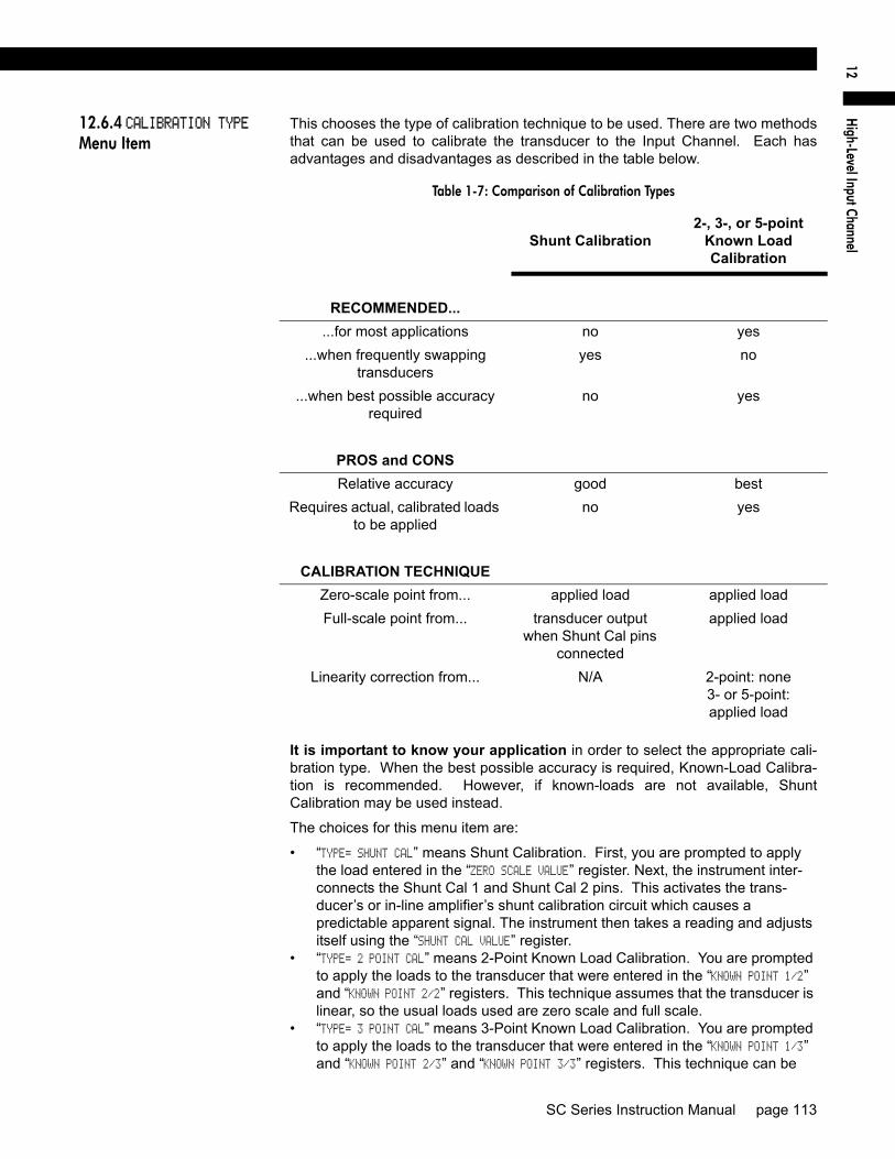
High-Level Input Channel
12
12.6.4 CALIBRATION TYPE Menu Item
This chooses the type of calibration technique to be used. There are two methodsthat can be used to calibrate the transducer to the Input Channel. Each hasadvantages and disadvantages as described in the table below.
It is important to know your application in order to select the appropriate cali-bration type. When the best possible accuracy is required, Known-Load Calibra-tion is recommended. However, if known-loads are not available, ShuntCalibration may be used instead.
The choices for this menu item are:
• “TYPE= SHUNT CAL” means Shunt Calibration. First, you are prompted to apply the load entered in the “ZERO SCALE VALUE” register. Next, the instrument inter-connects the Shunt Cal 1 and Shunt Cal 2 pins. This activates the trans-ducer’s or in-line amplifier’s shunt calibration circuit which causes a predictable apparent signal. The instrument then takes a reading and adjusts itself using the “SHUNT CAL VALUE” register.
• “TYPE= 2 POINT CAL” means 2-Point Known Load Calibration. You are prompted to apply the loads to the transducer that were entered in the “KNOWN POINT 1/2” and “KNOWN POINT 2/2” registers. This technique assumes that the transducer is linear, so the usual loads used are zero scale and full scale.
• “TYPE= 3 POINT CAL” means 3-Point Known Load Calibration. You are prompted to apply the loads to the transducer that were entered in the “KNOWN POINT 1/3” and “KNOWN POINT 2/3” and “KNOWN POINT 3/3” registers. This technique can be
Table 1-7: Comparison of Calibration Types
Shunt Calibration2-, 3-, or 5-point
Known Load Calibration
RECOMMENDED......for most applications no yes
...when frequently swapping transducers
yes no
...when best possible accuracy required
no yes
PROS and CONSRelative accuracy good best
Requires actual, calibrated loads to be applied
no yes
CALIBRATION TECHNIQUEZero-scale point from... applied load applied loadFull-scale point from... transducer output
when Shunt Cal pins connected
applied load
Linearity correction from... N/A 2-point: none3- or 5-point:applied load
SC Series Instruction Manual page 113

used to compensate for the non-linearity in the transducer. The usual loads used are zero scale, half scale and full scale, but you are not restricted to these loads.
• “TYPE= 5 POINT CAL” means 5-Point Known Load Calibration. You are prompted to apply the loads to the transducer that were entered in the “KNOWN POINT 1/5”, “KNOWN POINT 2/5”, “KNOWN POINT 3/5”, “KNOWN POINT 4/5” and “KNOWN POINT 5/5” regis-ters. This technique can be used to compensate for the non-linearity in the transducer. The usual loads used are zero scale, one-quarter scale, half scale, three-quarters scale and full scale, but you are not restricted to these loads.
The selection of the calibration type affects what menu items appear in the CALI-BRATION DATA sub-menu.
page 114 008-0608-00

High-Level Input Channel
12
12.6.5 CALIBRATION DATA Sub-Menu
This enters the values that will be used by the instrument when it calibrates itselfto the transducer. The menu items that are displayed will change according towhat the CALIBRATION TYPE is set for.
FULL SCALE VOLT orFULL SCALE CURR Menu Item
The nominal transducer/amplifier output when its full-scale load is applied to it, involts or milliamps. This menu item is used by the instrument to set gain of itsamplifier circuit. This value is normally found on the transducer’s Certificate ofCalibration or amplifier’s Application Note.
FULL SCALE VALUE Menu Item The transducer’s full-scale output in engineering units.
It is available only with the Shunt Calibration type.
ZERO SCALE VALUE Menu Item The transducer’s zero-scale output in engineering units, which is usually zero.
It is available only with the Shunt Calibration type.
SHUNT CAL VALUE Menu Item The shunt calibration value must be calculated by using information found on thetransducer’s Certificate of Calibration and the following formula:
The terms have the following meanings:
• Shunt-Calibration Output: The transducer’s output when its shunt calibration function is activated in Volts or milliamps. Sometimes called “Shunt Cal. Fac-tor”.
• Full-Scale Output: The transducer’s full-scale output in Volts or milliamps. Sometimes called “Calibration Factor”.
• Full-Scale Capacity: The transducer’s desired full-scale reading in engineering units (PSI, lbs, Kg, etc.). You may wish to convert the engineering units of this value. For example, if the transducer full scale is 3000 PSIG and you wish the channel to read in bar, you must convert 3000 PSIG into 206.84 bar.
This menu item is only available with the Shunt Calibration type.
To verify proper transducer/amplifier operation, you can activate the transducer’s/amplifier’s shunt calibration function while the instrument is in the RUN mode.Press and hold the [ENTER] button for three seconds; this will activate the trans-ducer’s/amplifier’s shunt calibration function and display the reading.
KNOWN POINT x/y Menu Items This enters the engineering units for the known-load calibration points. Thesepoints must match the actual loads that you will apply to the instrument during cal-ibration. The number of calibrations points depends on the CALIBRATION TYPE.
When using the 2-Point Known Load Calibration type, the following menu itemsare available:
• “KNOWN POINT 1/2”: point 1 of 2, usually 0% of the transducer’s full-scale capac-ity.
• “KNOWN POINT 2/2”: point 2 of 2, usually 100% of the transducer’s full-scale capacity.
When using the 3-Point Known Load Calibration type, the following menu itemsare available:
• “KNOWN POINT 1/3”: point 1 of 3, usually 0% of the transducer’s full-scale capac-
SHUNT CAL VALUEShunt-Calibration Output
Full-Scale Output------------------------------------------------------------- Full-Scale Capacity×=
SC Series Instruction Manual page 115

ity.• “KNOWN POINT 2/3”: point 2 of 3, usually 50% of the transducer’s full-scale capac-
ity.• “KNOWN POINT 3/3”: point 3 of 3, usually 100% of the transducer’s full-scale
capacity.
When using the 5-Point Known Load Calibration type, the following menu itemsare available:
• “KNOWN POINT 1/5”: point 1 of 5, usually 0% of the transducer’s full-scale capac-ity.
• “KNOWN POINT 2/5”: point 2 of 5, usually 25% of the transducer’s full-scale capac-ity.
• “KNOWN POINT 3/5”: point 3 of 5, usually 50% of the transducer’s full-scale capac-ity.
• “KNOWN POINT 4/5”: point 4 of 5, usually 75% of the transducer’s full-scale capac-ity.
• “KNOWN POINT 5/5”: point 5 of 5, usually 100% of the transducer’s full-scale capacity.
These menu items are only available with the Known-Load Calibration types.
NOTICETo insure both correct operation of the transducer and application of the load, the instrument expects the voltage or current applied at each known-load point to be increasing. For example, the load applied at Known-Load Point 2/2 must cause the transducer to produce a more positive voltage or current than at Known-Load Point 1/2.
page 116 008-0608-00
High-Level Input Channel
12
12.6.6 CALIBRATE Menu Item
This menu item performs a calibration according to what was entered in the CALI-BRATION TYPE and CALIBRATION DATA menu items.
If the CALIBRATION TYPE is Shunt Calibration...
• The display will read DOING SHUNT CAL, and prompt you to APPLY 00000 UNIT (where 00000 and UNIT are previously entered as ZERO SCALE VALUE and DISPLAY. UNITS. When you have applied this load to the transducer, press [ENTER].
• The display will then read WORKING and calibration will take place. Upon com-pletion, the display will indicate DONE and the instrument will return to the RUN mode.
If the CALIBRATION TYPE is 2-Point Known Load Calibration...
• The display will read DOING 2POINT CAL, and prompt you to APPLY 00000 UNIT (where 00000 and UNIT are previously entered as KNOWN POINT 1/2 and DISPLAY. UNITS). When you have applied this load to the transducer, press [ENTER].
• The display will read WORKING, then APPLY 01000 UNIT (where 01000 and UNIT are previously entered as KNOWN POINT 2/2 and DISPLAY. UNITS). When you have applied this load to the transducer, press [ENTER].
• Upon completion, the display will indicate DONE and the instrument will return to the RUN mode.
If the CALIBRATION TYPE is 3-Point Known Load Calibration...
• The display will read DOING 3POINT CAL, and prompt you to APPLY 00000 UNIT (where 00000 and UNIT are previously entered as KNOWN POINT 1/3 and DISPLAY. UNITS). When you have applied this load to the transducer, press [ENTER].
• The display will read WORKING, then APPLY 00500 UNIT (where 00500 and UNIT are previously entered as KNOWN POINT 2/3 and DISPLAY. UNITS). When you have applied this load to the transducer, press [ENTER].
• The display will read WORKING, then APPLY 01000 UNIT (where 01000 and UNIT are previously entered as KNOWN POINT 3/3 and DISPLAY. UNITS). When you have applied this load to the transducer, press [ENTER].
• Upon completion, the display will indicate DONE and the instrument will return to the RUN mode.
NOTICEBefore performing a calibration,• the transducer must be connected to the instrument, • the channel’s Excitation and Signal Jumpers must be set, • the CALIBRATION TYPE must be selected (see “CALIBRATION TYPE Menu Item”
on page 113), and • the CALIBRATION DATA must be entered (see “CALIBRATION DATA Sub-Menu”
on page 115).
NOTICEFor maximum accuracy, allow at least twenty minutes of warm-up with the exci-tation voltage applied to the transducer before calibration.
SC Series Instruction Manual page 117

If the CALIBRATION TYPE is 5-Point Known Load Calibration...
• The display will read DOING 5POINT CAL, and prompt you to APPLY 00000 UNIT (where 00000 and UNIT are previously entered as KNOWN POINT 1/5 and DISPLAY. UNITS). When you have applied this load to the transducer, press [ENTER].
• The display will read WORKING, then APPLY 00250 UNIT (where 00250 and UNIT are previously entered as KNOWN POINT 2/5 and DISPLAY. UNITS). When you have applied this load to the transducer, press [ENTER].
• The display will read WORKING, then APPLY 00500 UNIT (where 00500 and UNIT are previously entered as KNOWN POINT 3/5 and DISPLAY. UNITS). When you have applied this load to the transducer, press [ENTER].
• The display will read WORKING, then APPLY 00750 UNIT (where 00750 and UNIT are previously entered as KNOWN POINT 4/5 and DISPLAY. UNITS). When you have applied this load to the transducer, press [ENTER].
• The display will read WORKING, then APPLY 01000 UNIT (where 01000 and UNIT are previously entered as KNOWN POINT 5/5 and DISPLAY. UNITS). When you have applied this load to the transducer, press [ENTER].
• The display will now read RETURN PNTS.=NO. If you press [ENTER], the display will indicate DONE and the instrument will return to the RUN mode. If you use the [UP] button and [ENTER] to select RETURN POINTS=YES, you may now apply the same loads again but in reverse order. This will allow the instrument to measure and partially eliminate any hysteresis that may be present in the transducer. After the loads have been applied again, the display will indicate DONE and the instrument will return to the RUN mode.
page 118 008-0608-00

High-Level Input Channel
12
12.6.7 DAC SETUP Sub-Menu This sub-menu contains four items that control the Digital-to-Analog Converter(DAC) output of the channel.
DAC. CHANNEL Menu Item This chooses which channel will drive the DAC output. Normally, the DAC locatedon a particular channel will be driven by that channel, but that need not be thecase. For example, if several channels were assigned to load cells on a weighingplatform, the sum of all channels could (mathematically) drive one channel’s DACoutput.
If the DAC is set-up to be driven by its own channel’s tracking value, the AnalogOutput will have the frequency response specified by the channel’s FREQ. RESPONSEmenu item. Otherwise, the Analog Output will operate more slowly.
DAC. SOURCE Menu Item This designates the data source of the channel monitored by the analog output.
The options for this menu item are:
• “TRACK” means the live tracking value of the channel. • “PEAK” means the highest value of the channel since the peak/valley detector
was last cleared.• “VALLEY” means the lowest value of the channel since the peak/valley detector
was last cleared.If the DAC is set-up to be driven by its own channel’s tracking value, the AnalogOutput will have the frequency response specified by the channel’s FREQ. RESPONSEmenu item. Otherwise, the Analog Output will operate more slowly.
DAC. ZERO-SCALE Menu Item This specifies what value, in engineering units, corresponds to zero output on theAnalog Output.
“Zero output” might be 0 Volts, 2.5 Volts, 5 Volts, 4 mA or 12 mA depending on ifthe channel has a voltage or current output and how it is configured. See “AnalogOutput Configuration” on page 121 for details.
DAC. FULL-SCALE Menu Item Specifies what value, in engineering units, corresponds to full output on the Ana-log Output.
“Full output” might be 5 Volts, 10 Volts or 20 mA depending on if the channel hasa voltage or current output and how it is configured. See “Analog Output Configu-ration” on page 121 for details.
SC Series Instruction Manual page 119

12.6.8 DIAGNOSTICS Sub-Menu
DAC FULL SCALE Menu Item When this menu item is selected, the Analog Output of the channel is forced to itsfull-scale output, then DAC UPDATED is displayed. This is useful when calibrating ortrimming the readout connected to the Analog Output.
DAC ZERO SCALE Menu Item When this menu item is selected, the Analog Output of the channel is forced to itszero-scale output, then DAC UPDATED is displayed. This is useful when calibrating ortrimming the readout connected to the Analog Output.
VERSION INFO Menu Item This menu item displays the part number and revision level of the firmware usedby this channels microprocessor.
DISPLAY ADC Menu Item The options for this menu item are:
• “OFF” will allow the [VALUE] button to cycle through “TK” (tracking value), “HI” (peak value) and “LO” (valley value). This is the recommended option.
• “ON” will allow the “AD” (percentage of the Analog-to-Digital converter’s full-scale digitizing capability) display source to be available along with “TK” (track-ing value), “HI” (peak value) and “LO” (valley value) when the [VALUE] button is pressed on the front panel.
The Analog-to-Digital converter counts are displayed as a percentage from-100.00% to 100.00%.
This can be used to verify that the transducer’s output does not exceed the inputrange of the instrument. If the Analog-to-Digital converter readings display morethan +/-10% when there is no load on the transducer, the transducer has a highzero offset.
LINEARIZATION Menu Item The options for this menu item are:
• “ON” will allow linearization data obtained from either the Signature Module or a 3-Point or 5-Point Known Load Calibration to affect a channel’s scaled values. This is the recommended option.
• “OFF” will not allow linearization data to effect the channel’s scaled values. This is useful when diagnosing problems in a calibration procedure.
DISABLE CHANNEL Menu Item The options for this menu item are:
• “ON” will bypass the INITIALIZE and RUN modes of the channel. The track, peak and valley values of the channel are forced to 0.
• “OFF” will allow normal operation of the channel.
page 120 008-0608-00
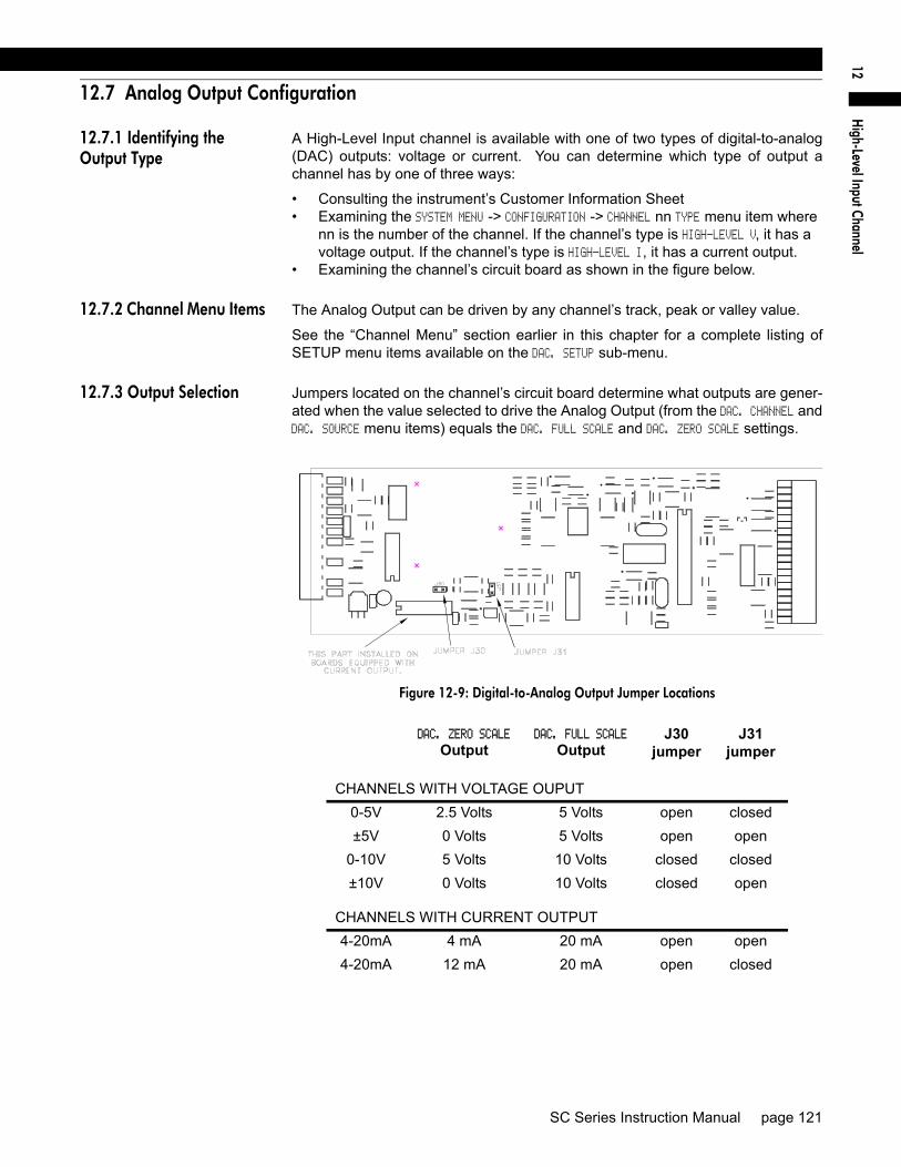
High-Level Input Channel
12
12.7 Analog Output Configuration
12.7.1 Identifying the Output Type
A High-Level Input channel is available with one of two types of digital-to-analog(DAC) outputs: voltage or current. You can determine which type of output achannel has by one of three ways:
• Consulting the instrument’s Customer Information Sheet• Examining the SYSTEM MENU -> CONFIGURATION -> CHANNEL nn TYPE menu item where
nn is the number of the channel. If the channel’s type is HIGH-LEVEL V, it has a voltage output. If the channel’s type is HIGH-LEVEL I, it has a current output.
• Examining the channel’s circuit board as shown in the figure below.
12.7.2 Channel Menu Items The Analog Output can be driven by any channel’s track, peak or valley value.
See the “Channel Menu” section earlier in this chapter for a complete listing ofSETUP menu items available on the DAC. SETUP sub-menu.
12.7.3 Output Selection Jumpers located on the channel’s circuit board determine what outputs are gener-ated when the value selected to drive the Analog Output (from the DAC. CHANNEL andDAC. SOURCE menu items) equals the DAC. FULL SCALE and DAC. ZERO SCALE settings.
Figure 12-9: Digital-to-Analog Output Jumper Locations
DAC. ZERO SCALE
OutputDAC. FULL SCALE
OutputJ30
jumperJ31
jumper
CHANNELS WITH VOLTAGE OUPUT0-5V 2.5 Volts 5 Volts open closed±5V 0 Volts 5 Volts open open
0-10V 5 Volts 10 Volts closed closed±10V 0 Volts 10 Volts closed open
CHANNELS WITH CURRENT OUTPUT4-20mA 4 mA 20 mA open open4-20mA 12 mA 20 mA open closed
SC Series Instruction Manual page 121
12.8 Troubleshooting
12.8.1 Error Messages See “Error Messages” on page 151 for information relating to error messages.
12.8.2 Common Problems and Solutions
Erratic Display Check electrical connections for continuity and the transducer’s and/or amplifier’swiring code from its Certificate of Calibration and Application Note.
Incorrect wiring may have shorted the excitation power supply. Use the correctwiring diagram to connect the transducer or amplifier to the instrument.
Make sure that the load on the transducer is constant.
Check input voltage or current to the (+)Signal (“+SIG”) and (-)Signal (“-SIG”) pinswith a multi-meter.
Blank Display Incorrect wiring may have shorted the ±15 VDC excitation power supply. Use thecorrect wiring diagram to connect the transducer or amplifier to the instrument.
+OVLD or -OVLD on Display Indicates that the voltage across the (+)Signal (“+SIG”) and (-)Signal (“-SIG”) pinsis overranging or underranging the amplifier circuit. Make certain all wires areconnected properly.
If you remove all load from the transducer and you still see this message, the(+)Excitation (“+EXC”) or (-)Excitation (“-EXC”) pins may be shorted to the (+)Sig-nal (“+SIG”) or (-)Signal (“-SIG”) pins.
If you remove all load from the transducer and you get a numeric reading, thetransducer may have a high zero offset. Use the channel’s SETUP menu and setDIAGNOSTICS -> DISPLAY ADC to “ON”; in the RUN mode this will allow the [VALUE] but-ton to display raw A/D readings as a percentage of its full-scale. If the raw A/Dreadings display more than +/-10% when there is no load on the transducer, thetransducer has a high zero offset.
Analog Output Incorrect Make certain of the type of Analog Output (voltage or current) that the channel isequipped with; see “Identifying the Output Type” on page 121.
Use the DIAGNOSTICS -> DAC FULL SCALE and DIAGNOSTICS -> DAC ZERO SCALE menu items toforce the Analog Output to a known output. Then, adjust your readout device,panel meter, PLC or data acquisition system to match.
Check the output selection jumpers; see “Output Selection” on page 121.
Auxiliary Function Pins Not Operating
Make sure that the AUX1 FUNCTION or AUX2 FUNCTION SETUP menu items are set cor-rectly; if they are set to DISABLED then they will not operate.
The Auxiliary Function (“AUX1” and “AUX2”) pins must be connected to pin 10,not pin 8, to activate them.
Sensitivity to EMI/RFI To obtain maximum immunity to electromagnetic or radio frequency interference,make certain that the shields of the transducer cables are connected to the “cableshield connection screw” on the rear panel of the instrument. See “Wiring” onpage 98, “External Arrangement of AC powered SC1000 and SC2000” onpage 27 and “External Arrangement of Model SC3004” on page 33.
page 122 008-0608-00

Relay O
utput Channel13
Chapter 13Relay Output Channel
13.1 Features
13.1.1 First Channel Installed
The first Relay Output channel installed in an instrument supplements the stan-dard four limits (Limit 1, Limit 2, Limit 3 and Limit 4) . Its four, dry contact relay out-puts will mirror the Limit Outputs pins of the System connector.
In the SYSTEM -> CONFIGURATION sub-menu, channels of this type are identified as LIMIT01-04.
13.1.2 Second Channel Installed
The second Relay Output channel installed in an instrument adds another fourlimits to the instrument (Limit 5, Limit 6, Limit 7 and Limit 8). Its relay outputsshow the status of these limits.
In the SYSTEM -> CONFIGURATION sub-menu, channels of this type are identified as LIMIT05-08.
13.1.3 Third Channel Installed
The third Relay Output channel installed in an instrument adds another four limitsto the instrument (Limit 9, Limit 10, Limit 11 and Limit 12). Its relay outputs showthe status of these limits.
In the SYSTEM -> CONFIGURATION sub-menu, channels of this type are identified as LIMIT09-12.
13.1.4 Fourth Channel Installed
The fourth Relay Output channel installed in an instrument adds another four lim-its to the instrument (Limit 13, Limit 14, Limit 15 and Limit 16). Its relay outputsshow the status of these limits.
In the SYSTEM -> CONFIGURATION sub-menu, channels of this type are identified as LIMIT13-16.
SC Series Instruction Manual page 123
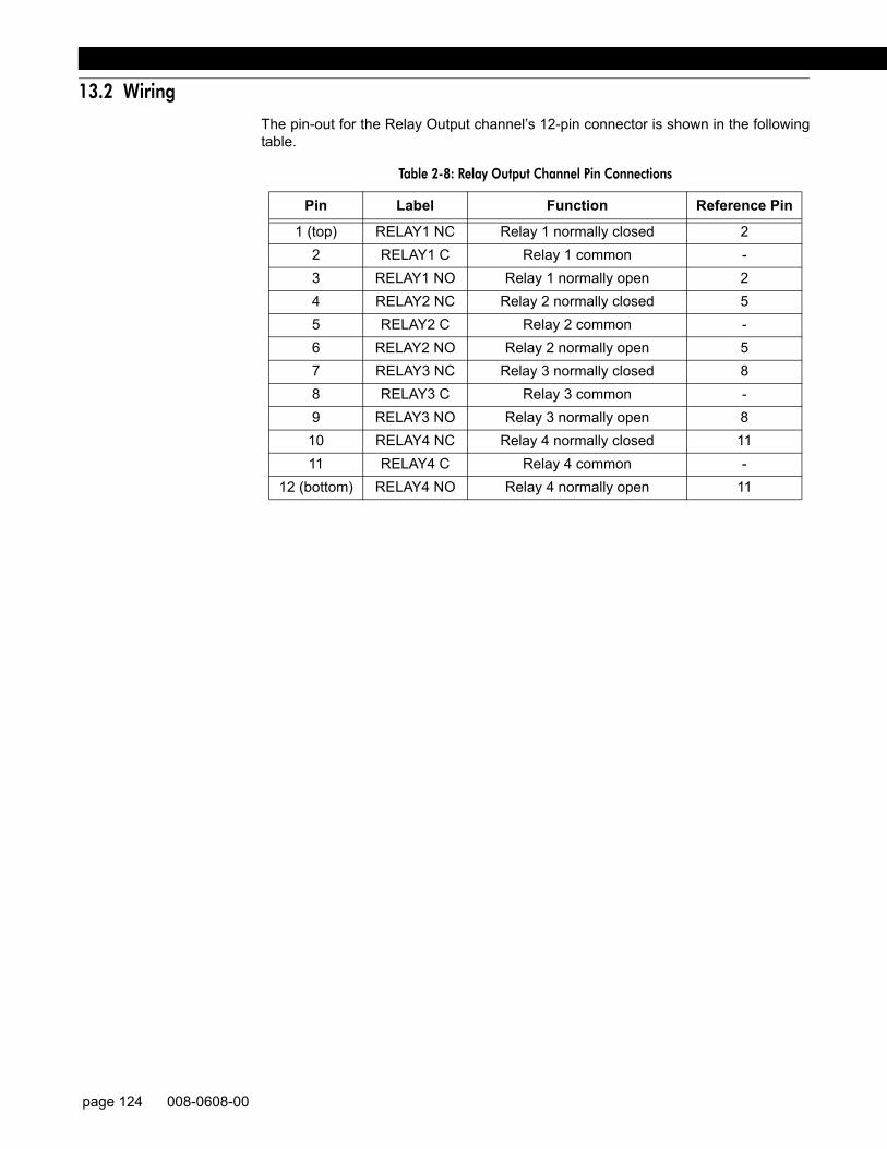
13.2 Wiring
The pin-out for the Relay Output channel’s 12-pin connector is shown in the followingtable.
Table 2-8: Relay Output Channel Pin Connections
Pin Label Function Reference Pin
1 (top) RELAY1 NC Relay 1 normally closed 22 RELAY1 C Relay 1 common -3 RELAY1 NO Relay 1 normally open 24 RELAY2 NC Relay 2 normally closed 55 RELAY2 C Relay 2 common -6 RELAY2 NO Relay 2 normally open 57 RELAY3 NC Relay 3 normally closed 88 RELAY3 C Relay 3 common -9 RELAY3 NO Relay 3 normally open 8
10 RELAY4 NC Relay 4 normally closed 1111 RELAY4 C Relay 4 common -
12 (bottom) RELAY4 NO Relay 4 normally open 11
page 124 008-0608-00

Relay O
utput Channel13
13.3 Setup Procedure
If you are not familiar with operating the instrument in the SETUP menu mode,see “SETUP Menu mode” on page 23. A listing of all menu item is given in “SetupMenu Reference” on page 157.
Step 1: Wire to the channel’s connector.See the “Wiring” section earlier in this chapter for details.
Step 2: Use the appropriate Limit Menu to setup the limits. See “Limits” on page 53 for information about limits.
NOTICEA SensoCode program running on a Mathematics Virtual Channel may over-ride the default behavior of the relay outputs. Consult the Customer Information Sheet included with your instrument for details.
SC Series Instruction Manual page 125

13.4 Specifications
RELAY OUTPUTQuantity and Type 4 form C
Contact Rating 0.5A @ 50VAC max. (consult factory for 125VAC max. operation)
1A @ 30VDC max.
page 126 008-0608-00

Relay O
utput Channel13
13.5 Channel Menu
The Relay Output channel’s SETUP menu allows you to manually turn the relayson and off to verify that they are functioning. To change the operation of the limits,see “Limit Menus” on page 55.
Detailed instructions on operating the instrument in the SETUP Menu mode canbe found in “SETUP Menu mode” on page 23. A diagram of all menus is locatedin “Setup Menu Reference” on page 157.
13.5.1 DIAGNOSTICS Sub-Menu
RELAY 1 Menu Item The options for this menu item are:
• “ON” will turn the relay on.• “OFF” will turn the relay off.
RELAY 2 Menu Item The options for this menu item are:
• “ON” will turn the relay on.• “OFF” will turn the relay off.
RELAY 3 Menu Item The options for this menu item are:
• “ON” will turn the relay on.• “OFF” will turn the relay off.
RELAY 4 Menu Item The options for this menu item are:
• “ON” will turn the relay on.• “OFF” will turn the relay off.
SC Series Instruction Manual page 127

page 128 008-0608-00

DAC O
utput Channel14
Chapter 14DAC Output Channel
14.1 Features
The DAC Output channel uses a digital-to-analog converter to generate a voltageor current from any channel’s track, peak or valley value. This type of channel isoften used to provide a Mathematics Virtual channel with an analog output.
SC Series Instruction Manual page 129

14.2 Wiring
Connect your readout instrument to a DAC Output channel by wiring it to the 12-pinconnector of that channel. The Customer Information Sheet that shipped with theinstrument describes which cards are installed in each channel. The pin-out for thisconnector is shown on the following table.
The Analog Output and Analog Return pins are electrically isolated from all other pinson the instrument.
Table 3-9: DAC Output Channel Pin Connections
Pin Label Function Reference Pin
1 (top) N/C No connection2 N/C No connection3 N/C No connection4 N/C No connection5 N/C No connection6 N/C No connection7 +OUT Analog Output 88 -OUT Analog Return -9 N/C No connection
10 N/C No connection11 N/C No connection12
(bottom)N/C No connection
page 130 008-0608-00

DAC O
utput Channel14
14.3 Setup Procedure
If you are not familiar with operating the instrument in the SETUP menu mode,see “SETUP Menu mode” on page 23. A listing of all menu items is given in“Setup Menu Reference” on page 157.
Step 1: Determine if you have a Voltage DAC Output channel or a Current DACOutput channel.Check the instrument’s Customer Information Sheet, or see “Identifying theOutput Type” on page 135.
Step 2: Wire the readout instrument to the channel’s connector.See the “Wiring” section earlier in this chapter for details.
Step 3: Select the value (channel and source) used to drive the Analog Output See the “Channel Menu” on page 133 for details.
Step 4: Select the full-scale and zero-scale settings used to drive the Analog Out-put.See the “Channel Menu” on page 133 for details.
SC Series Instruction Manual page 131

14.4 Specifications
ANALOG OUTPUTVoltage range (voltage output
channels)5, ±5 or 10 VDC
Current range (current outputchannels)
4-20 mA
Source any channel’s track, peak or valley valueIsolation 500V
Resolution 12 bitsUpdate Rate depends on how many channels are
installed in the instrument
page 132 008-0608-00

DAC O
utput Channel14
14.5 Channel Menu
Each DAC Output channel is configured and calibrated via its channel menu.Detailed instructions on operating the instrument in the SETUP Menu mode canbe found in “SETUP Menu mode” on page 23. A diagram of all menus is locatedin “Setup Menu Reference” on page 157.
14.5.1 DAC SETUP Sub-Menu This sub-menu contains four items that controls the analog output of the channel.
DAC. CHANNEL Menu Item This chooses which channel will drive the Digital-to-Analog Converter (DAC) out-put.
DAC. SOURCE Menu Item This designates the data source of the channel monitored by the analog output.Each channel has three data sources: the live tracking value (TRACK), its highestvalue (PEAK), and its lowest value (VALLEY).
The options for this menu item are:
• “TRACK” means the live tracking value of the channel. • “PEAK” means the highest value of the channel since the peak/valley detector
was last cleared.• “VALLEY” means the lowest value of the channel since the peak/valley detector
was last cleared.
DAC. ZERO-SCALE Menu Item This specifies what value, in engineering units, corresponds to zero output on theAnalog Output.
“Zero output” might be 0 Volts, 2.5 Volts, 5 Volts, 4 mA or 12 mA depending on ifthe channel has a voltage or current output and how it is configured. See the“Digital-to-Analog Output” section of this chapter for details.
This menu item is not automatically updated by another channel’s Signature Mod-ule equipped transducer.
DAC. FULL-SCALE Menu Item This specifies what value, in engineering units, corresponds to full output on theAnalog Output.
“Full output” might be 5 Volts, 10 Volts or 20 mA depending on if the channel hasa voltage or current output and how it is configured. See the “Digital-to-AnalogOutput” section of this chapter for details.
This menu item is not automatically updated by another channel’s Signature Mod-ule equipped transducer.
SC Series Instruction Manual page 133

14.5.2 DIAGNOSTICS Sub-Menu
DAC FULL SCALE Menu Item When this menu item is selected, the Analog Output of the channel is forced to its full-scale output, then DAC UPDATED is displayed. This is useful when calibrating or trimmingthe readout connected to the Analog Output.
DAC ZERO SCALE Menu Item When this menu item is selected, the Analog Output of the channel is forced to itszero-scale output, then DAC UPDATED is displayed. This is useful when calibrating or trim-ming the readout connected to the Analog Output.
page 134 008-0608-00
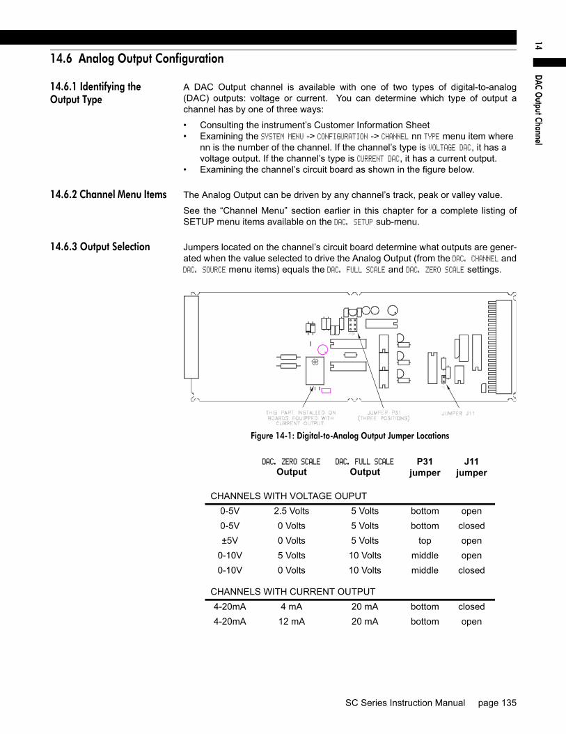
DAC O
utput Channel14
14.6 Analog Output Configuration
14.6.1 Identifying the Output Type
A DAC Output channel is available with one of two types of digital-to-analog(DAC) outputs: voltage or current. You can determine which type of output achannel has by one of three ways:
• Consulting the instrument’s Customer Information Sheet• Examining the SYSTEM MENU -> CONFIGURATION -> CHANNEL nn TYPE menu item where
nn is the number of the channel. If the channel’s type is VOLTAGE DAC, it has a voltage output. If the channel’s type is CURRENT DAC, it has a current output.
• Examining the channel’s circuit board as shown in the figure below.
14.6.2 Channel Menu Items The Analog Output can be driven by any channel’s track, peak or valley value.
See the “Channel Menu” section earlier in this chapter for a complete listing ofSETUP menu items available on the DAC. SETUP sub-menu.
14.6.3 Output Selection Jumpers located on the channel’s circuit board determine what outputs are gener-ated when the value selected to drive the Analog Output (from the DAC. CHANNEL andDAC. SOURCE menu items) equals the DAC. FULL SCALE and DAC. ZERO SCALE settings.
Figure 14-1: Digital-to-Analog Output Jumper Locations
DAC. ZERO SCALE
OutputDAC. FULL SCALE
OutputP31
jumperJ11
jumper
CHANNELS WITH VOLTAGE OUPUT0-5V 2.5 Volts 5 Volts bottom open0-5V 0 Volts 5 Volts bottom closed±5V 0 Volts 5 Volts top open
0-10V 5 Volts 10 Volts middle open0-10V 0 Volts 10 Volts middle closed
CHANNELS WITH CURRENT OUTPUT4-20mA 4 mA 20 mA bottom closed4-20mA 12 mA 20 mA bottom open
SC Series Instruction Manual page 135
14.7 Troubleshooting
14.7.1 Error Messages See “Error Messages” on page 151 for information relating to error messages.
14.7.2 Common Problems and Solutions
Analog Output Incorrect Make certain of the type of Analog Output (voltage or current) that the channel isequipped with; see “Identifying the Output Type” on page 135.
Use the DIAGNOSTICS -> DAC FULL SCALE and DIAGNOSTICS -> DAC ZERO SCALE menu items toforce the Analog Output to a known output. Then, adjust your readout device, panelmeter, PLC or data acquisition system to match.
Check the output selection jumpers; see “Output Selection” on page 135.
Check the “DAC SETUP -> DAC. ZERO-SCALE” and “DAC SETUP -> DAC FULL-SCALE” menu items.
Sensitivity to EMI/RFI To obtain maximum immunity to electromagnetic or radio frequency interference,make certain that the shield of the cable is connected to ground/earth only at the read-out device. The shield of the cable should not be connected to the instrument.
page 136 008-0608-00

DAC O
utput Channel14
SC Series Instruction Manual page 137

page 138 008-0608-00

Split Display Virtual Channel
15
Chapter 15Split Display Virtual Channel
15.1 Features
The Split Display Virtual Channel allows the display of two track, peak or valleyvalues from any two channels at the same time. One value is displayed on the leftside of the display, and another value is displayed on the right side.
The display setup used to format each value is inherited from the source channelof the value.
Split Displays are most useful on chassis with a 16-character display such as theModels SC1000, SC2000 and SC2001. The quad-line, 20-character display ofthe Model SC3004, however, already allows an Input Channel to show its ownTrack & Peak, Track & Valley or Peak & Valley values on the display at the sametime. Thus, a Split Display Virtual Channel is not generally used on an ModelSC3004.
15.2 Wiring
A Virtual Channel exists in software only; it does not occupy a physical slot insideof the instrument’s chassis. However, a Virtual Channel does require a channelnumber.
There is no rear-panel connector for a Virtual Channel.
15.3 Setup Procedure
If you are not familiar with operating the instrument in the SETUP menu mode,see “SETUP Menu mode” on page 23. A listing of all menu item is given in “SetupMenu Reference” on page 157.
Step 1: Enter the value to be displayed on the left side with LEFT CHANNEL and LEFTSOURCE.
Step 2: Enter the value to be displayed on the right side with RIGHT CHANNEL andRIGHT SOURCE.
SC Series Instruction Manual page 139

15.4 Channel Menu
Detailed instructions on operating the instrument in the SETUP Menu mode can befound in “SETUP Menu mode” on page 23. A diagram of all menus is located in“Setup Menu Reference” on page 157.
LEFT CHANNEL Menu Item This specifies the channel that is displayed on the left half of the split display.
LEFT SOURCE Menu Item This lets you designate the data source of the channel monitored by the left half of thesplit display. Each channel has three data sources: the live tracking value (TRACK),its highest value (PEAK), and its lowest value (VALLEY).
The options for this menu item are:
• “TRACK” means the live tracking value of the channel. • “PEAK” means the highest value of the channel since the peak detector was last
cleared.• “VALLEY” means the lowest value of the channel since the valley detector was last
cleared.
RIGHT CHANNEL Menu Item This specifies the channel that is displayed on the right half of the split display.
RIGHT SOURCE Menu Item This lets you designate the data source of the channel monitored by the right half ofthe split display. Each channel has three data sources: the live tracking value(TRACK), its highest value (PEAK), and its lowest value (VALLEY).
The options for this menu item are:
• “TRACK” means the live tracking value of the channel. • “PEAK” means the highest value of the channel since the peak detector was last
cleared.• “VALLEY” means the lowest value of the channel since the valley detector was last
cleared.
LEAVE MENU Menu Item When the menu item is displayed, press [ENTER] to leave this menu. Press [EXIT] toreturn to the RUN mode.
15.5 Troubleshooting
Front Panel Buttons not Operating in RUN Mode
When a Split Display Virtual channel is displayed the [VALUE], [CLEAR] and [TARE]buttons have no effect. To change one of the values shown on a Split Display Virtualchannel, use the its SETUP menu. To clear peak/valley values or tare an Input chan-nel, use the [CHANNEL] button to select an Input channel and then use the [CLEAR]or [TARE] buttons.
page 140 008-0608-00

Split Display Virtual Channel
15
SC Series Instruction Manual page 141

page 142 008-0608-00
M
athematics Virtual Channel
16
Chapter 16Mathematics Virtual Channel
16.1 Features
The Mathematics Virtual Channel is a powerful, flexible means to allow SC SeriesInstruments to perform simple to moderate functions that previously required theuse of expensive programmable logic controllers (PLC).
A Mathematics Virtual Channel is akin to a PLC; it can execute programs writtenin an interpretive language called SensoCode. At the time of order, your specificapplication is analyzed by our sales and engineering staff and one or more Senso-Code programs are created. These SensoCode programs are loaded into theMathematics Virtual channels of the instrument at the factory. The end result is aninstrument that meets your specific needs but is built with “off-the-shelf” hardwareand software.
SensoCode programs allow the instrument to perform a variety of functionsincluding:
• Mathematics: addition, subtraction, multiplication, division, square roots, etc.• Logical: if/then condition statements, comparison of values• Timing• Input: from any channel’s track, peak or valley values, open-collector inputs,
constant user-entered values from the SETUP menu• Output: Each Mathematics Channel generates its own track, peak, and valley
values. A SensoCode program can “take control” of the Limit Output and/or front panel indicator lights.
SC Series Instruction Manual page 143

16.2 Wiring
A Virtual Channel exists in software only; it does not occupy a physical slot inside ofthe instrument’s chassis. However, a Virtual Channel does require a channel number.
A SensoCode program that is executed by a Mathematics Virtual Channel can use theSystem connector’s Limit Output pins and Function Input pins for its own purposes.Consult the Customer Information Sheet and Supplemental Instructions included withthe particular instrument for details.
page 144 008-0608-00
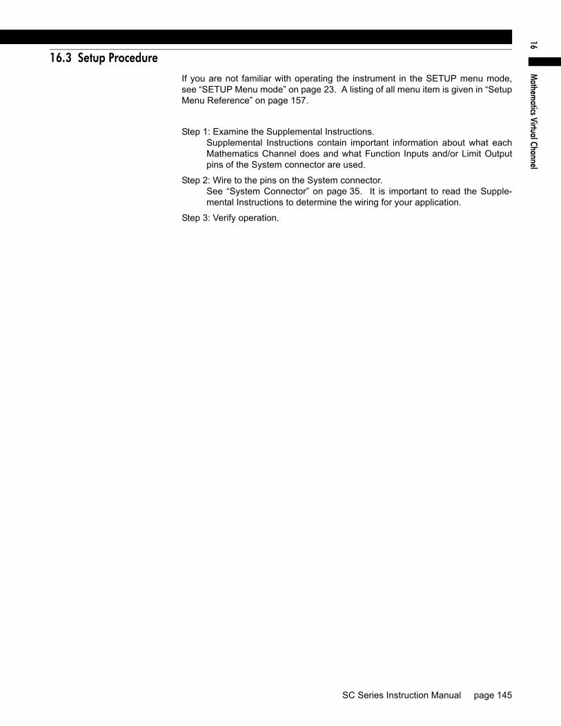
M
athematics Virtual Channel
16
16.3 Setup Procedure
If you are not familiar with operating the instrument in the SETUP menu mode,see “SETUP Menu mode” on page 23. A listing of all menu item is given in “SetupMenu Reference” on page 157.
Step 1: Examine the Supplemental Instructions.Supplemental Instructions contain important information about what eachMathematics Channel does and what Function Inputs and/or Limit Outputpins of the System connector are used.
Step 2: Wire to the pins on the System connector. See “System Connector” on page 35. It is important to read the Supple-mental Instructions to determine the wiring for your application.
Step 3: Verify operation.
SC Series Instruction Manual page 145

16.4 Channel Menu
Each Mathematics Virtual Channel can have its configuration and SensoCode pro-gramming examined via its channel menu. It is not possible to alter the SensoCodeprogram with the SETUP menu. Detailed instructions on operating the instrument inthe SETUP Menu mode can be found in “SETUP Menu mode” on page 23. A diagramof all menus is located in “Setup Menu Reference” on page 157.
16.4.1 SENSOCODE P/N Menu Item
This menu item displays the part number and revision level of the SensoCode pro-gram loaded in this Mathematics Virtual Channel.
16.4.2 USER VALUES Sub-Menu
This sub-menu contains menu items for each of the User Values. User Values areconstant numeric values that can be edited by the user and read by a SensoCode pro-gram. The use of each User Value depends on the SensoCode program loaded in theMathematics Virtual Channel.
By default, the four items on this menu are USER VALUE 1, USER VALUE 2, USER VALUE 3 andUSER VALUE 4. However, a SensoCode program can alter the menu item text for each ofthe User Values to make them more relevant to the operator. For example, USER VALUE1 might be re-titled JELLY BEAN COUNT.
16.4.3 VIEW SENSOCODE Menu Item
This menu item allows the display of each “step” (either an operand or an instruction)of the SensoCode program presently loaded into a Mathematics Virtual Channel.Pressing [ENTER] will display the next step of the SensoCode program until the entireprogram has been viewed.
SensoCode programs cannot be altered with the SETUP Mode menu; they can onlybe loaded via the serial port with the Instrument Utility Software.
16.4.4 VIEW COMMANDS Sub-Menu
This sub-menu contains menu items for each of the Command Strings that can beused by a SensoCode program. Command Strings are text constants that can beread by a SensoCode program. They are not able to be changed with the SETUPmenu. The use of each Command String depends on the SensoCode programloaded in the Mathematics Virtual Channel.
The items on this menu are COMMAND 0, COMMAND 1, COMMAND 2, COMMAND 3, COMMAND 4, COMMAND 5,COMMAND 6, and COMMAND 7.
page 146 008-0608-00

M
athematics Virtual Channel
16
16.4.5 DISPLAY SETUP Sub-Menu
This menu controls how data values are displayed by the channel and transmittedvia serial communications.
DISPLAY. DIGITS Menu Item Selects the number of digits displayed by the channel. The choices are:
• “5 DIGIT-BIPOLAR” displays both positive and negative numbers with five full dig-its (±99999).
• “6 DIGIT-UNIPLOAR” displays positive numbers with six full digits (999999) and negative numbers with five full digits (-99999).
• “7 DIGIT UNIPOLAR” displays positive number with seven full digits (9999999) and negative numbers with six digits (-999999).
DISPLAY. DECPT Menu Item Selects the decimal point location on the channel’s display and serial communica-tions output. Use the [UP] and [DOWN] buttons to move the decimal point to theright and left.
DISPLAY. COUNT-BY Menu Item Determines by what value the display increments or decrements. This will makethe display less sensitive to a noisy signal. The choices are:
• “00001” • “00002” • “00005” • “00010” • “00020” • “00050” • “00100” • “00200”
DISPLAY. UNITS Menu Item Specifies the four character label that is displayed to the right of the channel’s val-ues. This menu item doesn’t change the mathematical scaling of the channel’svalues; that is determined by the “CALIBRATION DATA -> FULL SCALE VALUE” menu item.
When a character position is flashing press the [UP] or [DOWN] button to changethe character. Press [ENTER] to advance to the next character.
DISPLAY. AVERAGE Menu Item Controls the speed with which the channel’s display values will update. Thechoices are:
• “ON” means that the display will update four times each second. The channel’s values will be averaged for 1/4 second, then displayed.
• “OFF” means that the channel’s display will update as quickly as possible.
SC Series Instruction Manual page 147

16.4.6 POWER-ON SOURCE Menu Item
This menu selects which value is displayed by the channel when first entering theRUN mode.
For single-line displays, the choices are:
• “TRACK” means the live tracking value of the channel. • “PEAK” means the highest value of the channel.• “VALLEY” means the lowest value of the channel.
For multi-line displays, the choices are:
• “TRACK” means the live tracking value of the channel. • “PEAK” means the highest value of the channel.• “VALLEY” means the lowest value of the channel.• “TRACK / PEAK” means the live tracking value and the highest value of the channel.• “TRACK / VALLEY” means the live tracking value and the lowest value of the channel.• “PEAK / VALLEY” means the highest and lowest values of the channel.
page 148 008-0608-00

M
athematics Virtual Channel
16
16.5 Troubleshooting
See “Error Messages” on page 151 for information relating to error messages.
NOTICESupplemental Instructions included with the instrument may contain important information about which indicator lights, Function Input pins and/or Limit Output pins of the System connector are used by the Mathematics Virtual channel.
SC Series Instruction Manual page 149

page 150 008-0608-00

Error M
essages17
Chapter 17Error Messages
17.1 Overview
If the instrument detects an error during the RUN, INITIALIZE, or SETUP modes,it stops operation and enters its ERROR mode as described in “Operating Modes”on page 19.
The most frequent causes of error messages are:
• Wiring/electrical connection problems• Misplaced address jumpers when installing or removing channel circuit
boards• Swapping channel circuit boards between instruments• Incorrect calibration of the transducer to the instrument
SC Series Instruction Manual page 151

17.2 Error Message List
Error 05, DIVIDE BY ZERO A Mathematics Virtual channel has attempted to divide by zero.
Error 07, SQUARE ROOT A Mathematics Virtual channel has attempted to take the square root of a negativenumber.
Error 09, LOG/LN A Mathematics Virtual channel has attempted to take the logarithm of either zero or anegative number.
Error 16, +15V SUPPLY HIGH The internal +15 VDC power supply is generating a voltage that is too high.
Error 17, +15V SUPPLY LOW The internal +15 VDC power supply is generating a voltage that is too low. Check thewiring between the instrument and the transducer or amplifier.
Error 18, -15V SUPPLY HIGH The internal -15 VDC power supply is generating a voltage that is too high (more pos-itive). Check the wiring between the instrument and the transducer or amplifier.
Error 19, -15V SUPPLY LOW The internal -15 VDC power supply is generating a voltage that is too low (more nega-tive).
Error 20, CHANNEL >MAXCH An invalid channel number has been encountered by the instrument. Restart theinstrument. If this error persists, contact our Service department with the informationfound in the SYSTEM MENU -> SOFTWARE REV. menu item.
Error 21, BLOWN STACK The instrument’s software stack has overflowed. Restart the instrument. If this errorpersists, contact our Service department with the information found in the SYSTEM MENU -> SOFTWARE REV. menu item.
Error 22, TYPE NOT FOUND The instrument has not been programmed to understand the type of channel. Contactour Service department with the information found in the SYSTEM MENU -> SOFTWARE REV.menu item.
Error 23, CAN'T RENDER FS The full-scale value of the transducer cannot be rendered on the display with theselected DISPLAY SETUP menu settings. Change the DISPLAY SETUP menu settings to bettermatch the transducer’s capacity.
Error 24, SIG.MOD CRC ROM A checksum error occurred while reading a Signature Module’s read-only-memory.Check the wiring and restart the instrument. This error may occur with very long cablelengths.
Error 25, SIG.MOD CRC READ A checksum failure occurred reading data from a Signature Module. Check the wiring.This error may be caused by a faulty Signature Module.
Error 26, NO SIG.MOD. No Signature Module was detected during UPDATE SIG.MOD. or DEFAULT SIG.MOD. Checkwiring.
Error 27, S.EE WRITE NAK The channel’s EEPROM could not be detected during a write operation. Check thatthe channel’s address jumpers are set properly so that each card has an uniqueaddress.
Error 28, S.EE READ NAK The channel’s EEPROM could not be detected during a read operation. Check thatthe channel’s address jumpers are set properly.
page 152 008-0608-00

Error M
essages17
Error 29, S.EE VERIFY FAIL A verification failure occurred during a write operation to the channel’s EEPROM.Restart the instrument.
Error 30, S.EE ERASE NAK The channel’s EEPROM could not be detected during an erase operation. Checkthat the channel’s address jumpers are set properly.
Error 31, BLANK IDENT The channel does not appear to have been installed properly. This occurs if youswap Input or Output boards without using SYSTEM MENU -> INSTALL CHANNEL to formatthe channel’s EEPROM.
Error 32, BOGUS EE ADDR An invalid address has been passed to the programmer. Restart the instrument. Ifthis problem persists, contact our Service department with the information foundin the SYSTEM MENU -> SOFTWARE REV. menu item.
Error 33, SIG.MOD WIRES The instrument has detected that the (+)Signature and (-)Signature pins (labeledas “+MEM” and “-MEM) are likely reversed.
Error 34, SIG.MOD MISMATCH The excitation type byte found inside a Signature Module indicates that the chan-nel is not designed to operate with that type of transducer.
Error 35, BOGUS MENU TYPE A menu contains an invalid menu type. Contact Sensotec with the informationfound in the SYSTEM MENU -> SOFTWARE REV. menu item.
Error 36, BAD EE TABLE The instrument doesn’t understand the EEPROM type setting for the channel.Contact Sensotec with the information found in the SYSTEM MENU -> SOFTWARE REV.
menu item.
Error 37, BAD PERSONALITY The channel doesn’t understand the given card type. Contact Sensotec with theinformation found in the SYSTEM MENU -> SOFTWARE REV. menu item.
Error 38, BAD FORMAT The channel’s EEPROM memory contains a display setting which is not under-stood by the instrument. Check that every item in the channel’s DISPLAY SETUP
menu has a valid setting.
Error 39, WRONG HARDWARE The channel type expected by the instrument for the channel number is not thechannel type that is physically installed. If you have changed the address jumperson one or more channels, replace them in their original configuration.
Error 41, SHUNT CAL ERROR The application of the shunt resistor did not affect the transducer’s output. Checkthe wiring and the transducer output with a voltmeter to verify proper operation.
If this is a Strain Gage Channel, make certain that the shunt calibration resistorinstalled on the circuit board is the correct value per the transducer’s CalibrationRecord.
If this is a High-Level Input Channel, make certain that the Shunt Cal 1 and ShuntCal 2 pins are connected to the correct pins of the transducer/amplifier.
Error 43, BAD IDENT CRC A checksum failure has occurred when reading a channel’s EEPROM. Restartthe instrument.
Error 44, BAD FUNCTION The instrument has requested that the channel perform a function that it is notcapable of. Restart the instrument.
Error 45, A/D NAK Hardware error. The channel’s Analog-to-Digital converter is not communicatingwith the channel’s microprocessor. Restart the instrument.
Error 46, SENSE WIRES The Strain Gage Channel’s (+)Sense and (-)Sense pins (labeled as “+SEN” and “-
SC Series Instruction Manual page 153

SEN”) are not connected to the (+)Excitation and (-)Excitation pins (labeled as “+EXC”and “-EXC”), respectively, This is most likely caused by the connector beingunplugged from the channel.
If you are not interested in the using this channel and you wish to suppress this error,see “DISABLE CHANNEL Menu Item” on page 75.
Error 47, BAD EE TYPE REQ When installing a channel, the EEPROM type requested by the channel is not valid.Contact Sensotec with the information found in the SYSTEM MENU -> SOFTWARE REV. menuitem.
Error 48, NULL MENU A menu contains a NULL item. Contact our Service department with the informationfound in the SYSTEM MENU -> SOFTWARE REV. menu item.
Error 49, NULL ACTION FCN A menu contains a NULL action function. Contact our Service department with theinformation found in the SYSTEM MENU -> SOFTWARE REV. menu item.
Error 50, EXCITATION The channel’s excitation voltage regulator has shut down because the protection cir-cuit that limits the output current has activated. This is most likely caused by a short ofthe (+)Excitation and (-)Excitation pins (labeled as “+EXC” and “-EXC”).
Error 51, CAN'T DO EXC. The channel’s EEPROM memory contains an excitation setting which is not under-stood by the instrument. Change the channel’s CALIBRATION DATA -> EXCITATION menuitem to another setting.
Error 52, SIG.MOD LENGTH R An unexpected length byte was found inside a Signature Module during a read opera-tion. Check the wiring.
Error 53, SIG.MOD RECTYPE An unexpected record type was found inside a Signature Module during a read opera-tion. Check the wiring.
Error 54, SIG.MOD LENGTH W An unexpected record type was found inside a Signature Module during a write opera-tion. Check the wiring and re-start the instrument.
Error 55, SIG.MOD VERIFY SP A data verification error occurred during a write operation to a Signature Module’sscratchpad. Check the wiring and re-start the instrument.
Error 56, SIG.MOD VERIFY A data verification error occurred during a write operation to a Signature Module.Check the wiring and re-start the instrument.
Error 57, WRONG SIG.MOD. You have attempted to perform an UPDATE SIG.MOD. operation with a different SignatureModule than what was connected when the instrument was powered up. Re-connectthe original transducer/Signature Module and restart the instrument.
Another cause of this error is described in the description for Error 68 below.
Error 58, WRONG EE VERSION The channel’s EEPROM memory data is not able to be used by this version of firm-ware. Make certain that you have not accidentally swapped channel circuit boardsbetween instruments. If you are certain that you want to use the channel circuit boardwith this instrument, you may reset the channel’s EEPROM memory data to factorydefaults with the SYSTEM MENU -> DEFAULT CHANNEL menu item.
Error 59, CAN’T DO SIG.MOD A Signature Module is connected to a channel which doesn’t support Signature Cali-bration. Only Strain Gage Input channels are designed to operate with Signature Cal-ibration.
Error 60, SLAVE TIMEOUT The channel’s microprocessor did not respond because the channel’s analog-to-digi-tal converter did not calibrate properly. Restart the instrument.
page 154 008-0608-00

Error M
essages17
Error 61, LOAD NOT GT LOAD A load applied during a known-load calibration was not greater than a previouslyapplied load. To insure both correct operation of the transducer and application of theload, the instrument expects the voltage applied at each known-load point to beincreasing. For example, the load applied at Known-Load Point 2/2 must cause thetransducer to produce a more positive voltage than at Known-Load Point 1/2.
If you are calibrating with a AC-AC LVDT Input channel, make certain that you havefollowed the procedure described in “Electrical Null and Transducer Mounting” onpage 93.
Error 62, SLAVE NAK The channel’s microprocessor is responding to a message, but it did not acknowledgeit correctly. Restart the instrument.
Error 67, LOADS NOT CLOSE During a 5-Point Known-Load calibration, you would typically apply loads at 0%, 25%,50%, 75% and 100% of the transducer’s full-scale and optionally calibrate the returnpoints of 75%, 50%, 25% and 0%. The instrument makes sure that transducer read-ings taken during the second application of the load are close to the readings takenduring the first application of the load. This insures both correct operation of the trans-ducer and application of the loads.
Error 68, CAN'T CALIBRATE The instrument has detected that the transducer presently connected to the channel isdifferent than the transducer the channel was last calibrated with. Ordinarily, theinstrument would perform a Shunt Calibration or mV/V Calibration. However, sincethe channel’s CALIBRATION TYPE menu item is set to one of the Known-Load Calibrationsettings, no calibration can take place. Either re-connect the original transducer oruse the SETUP menu to perform a calibration.
Error 70, CAN'T DO GAIN The channel’s EEPROM memory contains an input range setting which is beyond thecapabilities of the channel. Change the channel’s CALIBRATION DATA -> FULL SCALE MV/Vmenu item to another setting.
Error 71, SLAVE CHECKSUM The channel’s microprocessor did not send a correct checksum to the instrument.Restart the instrument.
Error 72, CAN'T DO FILTER The channel’s EEPROM memory contains a frequency response setting which is notunderstood by the instrument. Change the channel’s OPERATION -> FREQ. RESPONSE menuitem to another setting.
Error 73, SLAVE NOT INIT The channel’s microprocessor has not yet been initialized by the instrument. Restartthe instrument.
Error 74, SLAVE BAD REPLY The channel’s microprocessor replied with a message that was either not understoodor different than expected. Restart the instrument.
Error 75, SLAVE NOT FOUND The channel’s microprocessor did not respond. Restart the instrument.
Error 81, OPERAND EXPECTED The first step of a SensoCode program must be an Operand. The SensoCode pro-gram loaded in the Mathematics Virtual channel is invalid.
Error 82, BAD OPERAND The SensoCode program loaded into a Mathematics Virtual channel contains a badoperand.
Error 83, BAD INSTRUCTION The SensoCode program loaded into a Mathematics Virtual channel contains a badinstruction.
Error 84, BAD VALUE A Mathematics Virtual channel has attempted to get a value from a channel notinstalled in the instrument.
SC Series Instruction Manual page 155

Error 85, UNREACHABLE GOTO The destination step of a “Go to” Instruction is beyond the end of the SensoCode pro-gram. The SensoCode program loaded in the Mathematics Virtual channel is invalid.
Error 87, GOTO NOT JUMP The SensoCode program contains a “Go to” Instruction that has not been convertedinto a “Jump” Instruction. Restart the instrument.
page 156 008-0608-00

Setup M
enu Reference18
Chapter 18Setup Menu Reference
18.1 Navigation instructions
• Press [UP]+[DOWN] to enter the SETUP menu mode.• Press [UP] to move up.• Press [DOWN] to move down.• Press [ENTER] to select an item.• Press [EXIT] to re-start the instrument.
SC Series Instruction Manual page 157

Table 7-10: SETUP Menu
CHANNEL 01 MENU (menu varies according to channel type)CHANNEL 02 MENU (menu varies according to channel type)CHANNEL 03 MENU (menu varies according to channel type)CHANNEL 04 MENU (menu varies according to channel type)CHANNEL 05 MENU (menu varies according to channel type)CHANNEL 06 MENU (menu varies according to channel type)CHANNEL 07 MENU (menu varies according to channel type)CHANNEL 08 MENU (menu varies according to channel type)CHANNEL 09 MENU (menu varies according to channel type)CHANNEL 10 MENU (menu varies according to channel type)CHANNEL 11 MENU (menu varies according to channel type)CHANNEL 12 MENU (menu varies according to channel type)CHANNEL 13 MENU (menu varies according to channel type)CHANNEL 14 MENU (menu varies according to channel type)CHANNEL 15 MENU (menu varies according to channel type)CHANNEL 16 MENU (menu varies according to channel type)CHANNEL 17 MENU (menu varies according to channel type)CHANNEL 18 MENU (menu varies according to channel type)CHANNEL 19 MENU (menu varies according to channel type)CHANNEL 20 MENU (menu varies according to channel type)CHANNEL 21 MENU (menu varies according to channel type)CHANNEL 22 MENU (menu varies according to channel type)CHANNEL 23 MENU (menu varies according to channel type)LIMIT 01 MENU (see LIMIT MENU)LIMIT 02 MENU (see LIMIT MENU)LIMIT 03 MENU (see LIMIT MENU)LIMIT 04 MENU (see LIMIT MENU)LIMIT 05 MENU (optional)(see LIMIT MENU)LIMIT 06 MENU (optional)(see LIMIT MENU)LIMIT 07 MENU (optional)(see LIMIT MENU)LIMIT 08 MENU (optional)(see LIMIT MENU)LIMIT 09 MENU (optional)(see LIMIT MENU)LIMIT 10 MENU (optional)(see LIMIT MENU)LIMIT 11 MENU (optional)(see LIMIT MENU)LIMIT 12 MENU (optional)(see LIMIT MENU)LIMIT 13 MENU (optional)(see LIMIT MENU)LIMIT 14 MENU (optional)(see LIMIT MENU)LIMIT 15 MENU (optional)(see LIMIT MENU)LIMIT 16 MENU (optional)(see LIMIT MENU)SYSTEM MENU (see SYSTEM MENU)SERIAL COM MENU (see SERIAL COM MENU)DISPLAY MENU (see DISPLAY MENU)
page 158 008-0608-00

Setup M
enu Reference18
Table 7-11: System Menu
SYSTEM MENU SOFTWARE REVISION page 41 CONFIGURATION DISPLAY TYPE page 41 CHANNEL 01 TYPE
CHANNEL 02 TYPE
CHANNEL 03 TYPE
CHANNEL 04 TYPE
CHANNEL 05 TYPE
CHANNEL 06 TYPE
CHANNEL 07 TYPE
CHANNEL 08 TYPE
CHANNEL 09 TYPE
CHANNEL 10 TYPE
CHANNEL 11 TYPE
CHANNEL 12 TYPE
CHANNEL 14 TYPE
CHANNEL 15 TYPE
CHANNEL 16 TYPE
CHANNEL 17 TYPE
CHANNEL 18 TYPE
CHANNEL 19 TYPE
CHANNEL 20 TYPE
CHANNEL 21 TYPE
CHANNEL 22 TYPE
CHANNEL 23 TYPE
LEAVE SUB-MENU
DIAGNOSTICS OUTPUT 1, PIN 14 ON page 41 OFF
OUTPUT 2, PIN 15 ON
OFF
OUTPUT 3, PIN 16 ON
OFF
OUTPUT 4, PIN 17 ON
OFF
INPUT TEST page 41 SCAN TIME page 41 LEAVE SUB-MENU
INSTALL CHANNEL 65 STRAIN GAGE V page 42 66 STRAIN GAGE I
67 HIGH-LEVEL V
68 HIGH-LEVEL I
6B LVDT V OUT
6C LVDT I OUT
90 LIMIT 01-04
91 LIMIT 05-08
92 LIMIT 09-12
93 LIMIT 13-16
AB SPLIT DISPLAY
AE MATHEMATICS
DELETE CHANNEL page 44 DEFAULT CHANNEL page 44 LEAVE MENU
SC Series Instruction Manual page 159

Table 7-12: LIMIT MENU
LIMIT xx MENU LIMIT. ENABLE ON page 55 OFF
LIMIT. SETPOINT page 55 LIMIT. RETURN PNT page 55 LIMIT. ENERGIZE SIGNAL>SETPOINT page 55 SIGNAL<SETPOINT
SIGNAL INSIDE
SIGNAL OUTSIDE
LIMIT. LATCHING ON page 57 OFF
LIMIT. CHANNEL page 57 LIMIT. SOURCE TRACK page 57 PEAK
VALLEY
LEAVE MENU
Table 7-13: SERIAL COMMUNICATIONS Menu
SERIAL COM MENU INTERFACE page 49 ADDRESS page 49 BAUD RATE page 49 AUTO LINE-FEED page 49 TRANSMIT TEST page 49 LEAVE MENU
Table 7-14: DISPLAY Menu for Models SC2000, SC2001
DISPLAY MENU UPPER CHANNEL page 51 LOWER CHANNEL page 51 LOWER MODE BLANK page 51 LIMITS 01-04
CHANNEL
DISPLAY DISABLE ON page 51 OFF
LEAVE MENU
Table 7-15: DISPLAY Menu for Model SC3004
DISPLAY MENU POWERON CHANNEL page 51 LEAVE MENU
page 160 008-0608-00

Setup M
enu Reference18
Table 7-16: Strain Gage Input Channel Menu
CHANNEL xx MENU OPERATION AUTO-ZERO ON page 63 OFF
FREQ. RESPONSE 002. HERTZ/FAST page 63 002. HERTZ
008. HERTZ
016. HERTZ
032. HERTZ
050. HERTZ
100. HERTZ
250. HERTZ
500. HERTZ
800. HERTZ
POWER-ON SOURCE TRACK page 64 PEAK
VALLEY
LEAVE SUB-MENU
DISPLAY SETUP DISPLAY. DIGITS 5 DIGIT-BIPOLAR page 65 6 DIGIT-UNIPOLAR
7 DIGIT-UNIPOLAR
DISPLAY. DECPT 99999. page 65 9999.9
999.99
99.999
9.9999
.99999
DISPLAY. COUNTBY 00001 page 65 00002
00005
00010
00020
00050
00100
00200
DISPLAY. UNITS page 65 DISPLAY. AVERAGE ON page 65 OFF
LEAVE SUB-MENU
AUX1 FUNCTION DISABLED page 59 TRACK HOLD
HIGH/LOW HOLD
HIGH/LOW CLEAR
TARE ON
TARE OFF
AUX2 FUNCTION DISABLED page 59 TRACK HOLD
HIGH/LOW HOLD
HIGH/LOW CLEAR
TARE ON
TARE OFF
CALIBRATION TYPE TYPE=SHUNT CAL page 67 TYPE=MV/V CAL
SC Series Instruction Manual page 161

TYPE=2 POINT CAL
TYPE=3 POINT CAL
TYPE=5 POINT CAL
CALIBRATION DATA EXCITATION (menu varies with page 69 FULL-SCALE MV/V calibration type) FULL-SCALE VALUE
ZERO-SCALE VALUE
SHUNT CAL VALUE
KNOWN LOAD POINT 1/5
KNOWN LOAD POINT 2/5
KNOWN LOAD POINT 3/5
KNOWN LOAD POINT 4/5
KNOWN LOAD POINT 5/5
LEAVE SUB-MENU
CALIBRATE page 71 DAC SETUP DAC. CHANNEL page 73 DAC. SOURCE TRACK
PEAK
VALLEY
DAC. ZERO-SCALE
DAC. FULL-SCALE
LEAVE SUB-MENU
SIGNATURE MODULE UPDATE SIG.MOD? NO page 74 YES
DEFAULT SIG.MOD? NO
YES
UPDATE DAC SETUP? NO
YES
LEAVE SUB-MENU
DIAGNOSTICS DAC FULL SCALE page 75 DAC ZERO SCALE
VERSION INFO
DISPLAY ADC ON
OFF
LINEARIZATION ON
OFF
DISABLE CHANNEL ON
OFF
LEAVE SUB-MENU
LEAVE MENU
Table 7-16: Strain Gage Input Channel Menu (Continued)
page 162 008-0608-00
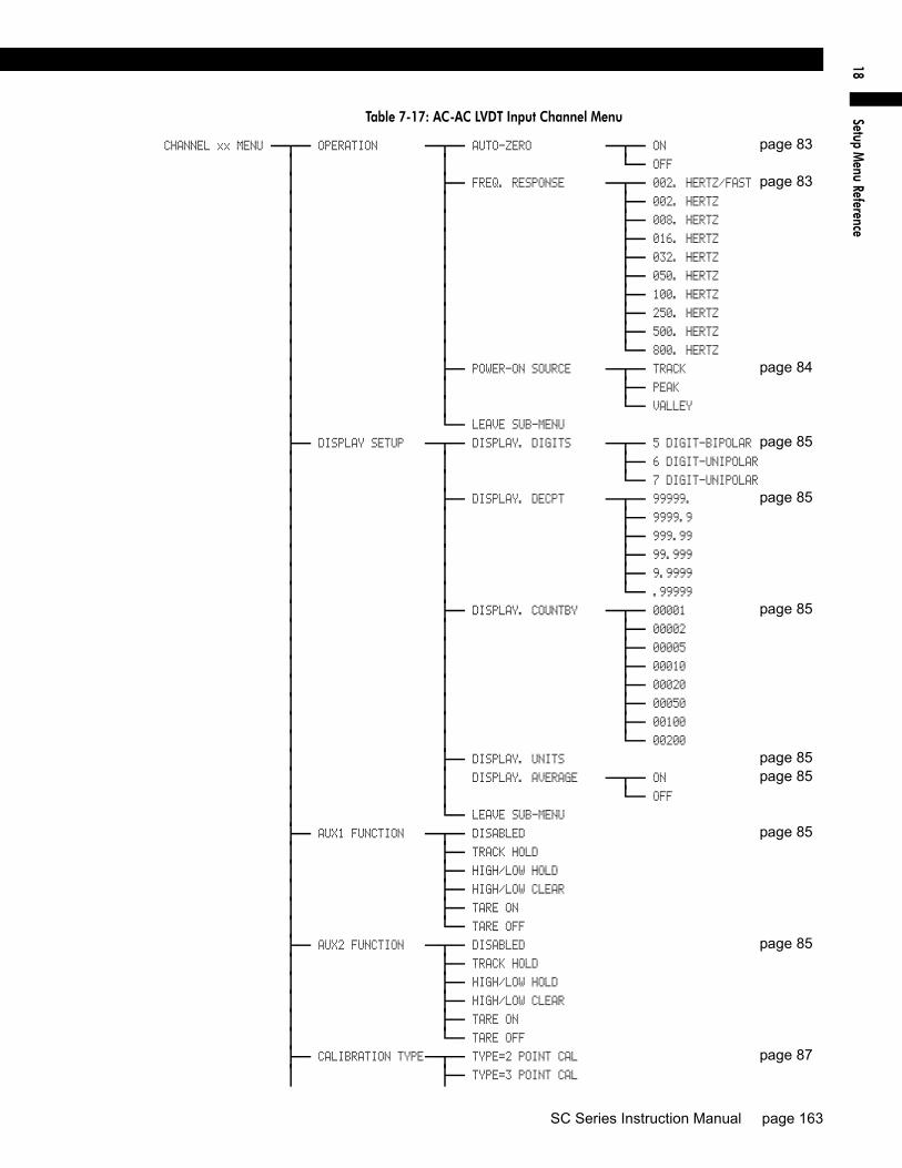
Setup M
enu Reference18
Table 7-17: AC-AC LVDT Input Channel Menu
CHANNEL xx MENU OPERATION AUTO-ZERO ON page 83 OFF
FREQ. RESPONSE 002. HERTZ/FAST page 83 002. HERTZ
008. HERTZ
016. HERTZ
032. HERTZ
050. HERTZ
100. HERTZ
250. HERTZ
500. HERTZ
800. HERTZ
POWER-ON SOURCE TRACK page 84 PEAK
VALLEY
LEAVE SUB-MENU
DISPLAY SETUP DISPLAY. DIGITS 5 DIGIT-BIPOLAR page 85 6 DIGIT-UNIPOLAR
7 DIGIT-UNIPOLAR
DISPLAY. DECPT 99999. page 85 9999.9
999.99
99.999
9.9999
.99999
DISPLAY. COUNTBY 00001 page 85 00002
00005
00010
00020
00050
00100
00200
DISPLAY. UNITS page 85 DISPLAY. AVERAGE ON page 85 OFF
LEAVE SUB-MENU
AUX1 FUNCTION DISABLED page 85 TRACK HOLD
HIGH/LOW HOLD
HIGH/LOW CLEAR
TARE ON
TARE OFF
AUX2 FUNCTION DISABLED page 85 TRACK HOLD
HIGH/LOW HOLD
HIGH/LOW CLEAR
TARE ON
TARE OFF
CALIBRATION TYPE TYPE=2 POINT CAL page 87 TYPE=3 POINT CAL
SC Series Instruction Manual page 163

TYPE=5 POINT CAL
CALIBRATION DATA FULL SCALE VRMS page 88 KNOWN LOAD POINT 1/5
KNOWN LOAD POINT 2/5
KNOWN LOAD POINT 3/5
KNOWN LOAD POINT 4/5
KNOWN LOAD POINT 5/5
LEAVE SUB-MENU
CALIBRATE page 89 DAC SETUP DAC. CHANNEL page 91 DAC. SOURCE TRACK
PEAK
VALLEY
DAC. ZERO-SCALE
DAC. FULL-SCALE
LEAVE SUB-MENU
DIAGNOSTICS DAC FULL SCALE page 92 DAC ZERO SCALE
VERSION INFO
DISPLAY ADC ON
OFF
LINEARIZATION ON
OFF
LEAVE SUB-MENU
LEAVE MENU
Table 7-17: AC-AC LVDT Input Channel Menu (Continued)
page 164 008-0608-00

Setup M
enu Reference18
Table 7-18: High-Level Input Channel Menu
CHANNEL xx MENU OPERATION AUTO-ZERO ON page 109 OFF
FREQ. RESPONSE 002. HERTZ/FAST page 109 002. HERTZ
008. HERTZ
016. HERTZ
032. HERTZ
050. HERTZ
100. HERTZ
250. HERTZ
500. HERTZ
800. HERTZ
POWER-ON SOURCE TRACK page 109 PEAK
VALLEY
LEAVE SUB-MENU
DISPLAY SETUP DISPLAY. DIGITS 5 DIGIT-BIPOLAR page 111 6 DIGIT-UNIPOLAR
7 DIGIT-UNIPOLAR
DISPLAY. DECPT 99999. page 111 9999.9
999.99
99.999
9.9999
.99999
DISPLAY. COUNTBY 00001 page 111 00002
00005
00010
00020
00050
00100
00200
DISPLAY. UNITS page 111 DISPLAY. AVERAGE ON page 111 OFF
LEAVE SUB-MENU
AUX1 FUNCTION DISABLED page 112 TRACK HOLD
HIGH/LOW HOLD
HIGH/LOW CLEAR
TARE ON
TARE OFF
AUX2 FUNCTION DISABLED page 112 TRACK HOLD
HIGH/LOW HOLD
HIGH/LOW CLEAR
TARE ON
TARE OFF
CALIBRATION TYPE TYPE=SHUNT CAL page 113 TYPE=2 POINT CAL
SC Series Instruction Manual page 165

TYPE=3 POINT CAL
TYPE=5 POINT CAL
CALIBRATION DATA FULL-SCALE VOLT/CURR(menu varies with page 115 FULL-SCALE VALUE calibration type) ZERO-SCALE VALUE
SHUNT CAL VALUE
KNOWN LOAD POINT 1/5
KNOWN LOAD POINT 2/5
KNOWN LOAD POINT 3/5
KNOWN LOAD POINT 4/5
KNOWN LOAD POINT 5/5
LEAVE SUB-MENU
CALIBRATE page 117 DAC SETUP DAC. CHANNEL page 119 DAC. SOURCE TRACK
PEAK
VALLEY
DAC. ZERO-SCALE
DAC. FULL-SCALE
LEAVE SUB-MENU
DIAGNOSTICS DAC FULL SCALE page 120 DAC ZERO SCALE
VERSION INFO
DISPLAY ADC ON
OFF
LINEARIZATION ON
OFF
DISABLE CHANNEL ON
OFF
LEAVE SUB-MENU
LEAVE MENU
Table 7-18: High-Level Input Channel Menu (Continued)
page 166 008-0608-00

Setup M
enu Reference18
Table 7-19: Relay Output Channel
CHANNEL xx MENU DIAGNOSTICS RELAY 1 ON page 127 OFF
RELAY 2 ON page 127 OFF
RELAY 3 ON page 127 OFF
RELAY 4 ON page 127 OFF
LEAVE SUB-MENU
LEAVE MENU
Table 7-20: DAC Output Channel Menu
CHANNEL xx MENU DAC SETUP DAC. CHANNEL page 133 DAC. SOURCE TRACK
PEAK
VALLEY
DAC. ZERO-SCALE
DAC. FULL-SCALE
LEAVE SUB-MENU
DIAGNOSTICS DAC FULL SCALE page 134 DAC ZERO SCALE
LEAVE SUB-MENU
LEAVE MENU
Table 7-21: Split Display Virtual Channel
CHANNEL xx MENU LEFT CHANNEL page 140 LEFT SOURCE TRACK page 140 PEAK
VALLEY
RIGHT CHANNEL page 140 RIGHT SOURCE TRACK page 140 PEAK
VALLEY
LEAVE MENU
SC Series Instruction Manual page 167

Table 7-22: Mathematics Virtual Channel
CHANNEL xx MENU SENSOCODE P/N page 146 USER VALUES USER VALUE 1 (item name may vary) page 146 USER VALUE 2 (item name may vary) USER VALUE 3 (item name may vary) USER VALUE 4 (item name may vary) LEAVE SUB-MENU
VIEW SENSOCODE page 146 VIEW COMMANDS COMMAND 0 page 146 COMMAND 1
COMMAND 2
COMMAND 3
COMMAND 4
COMMAND 5
COMMAND 6
COMMAND 7
LEAVE SUB-MENU
DISPLAY SETUP DISPLAY. DIGITS 5 DIGIT-BIPOLAR page 147 6 DIGIT-UNIPOLAR
7 DIGIT-UNIPOLAR
DISPLAY. DECPT 99999. page 147 9999.9
999.99
99.999
9.9999
.99999
DISPLAY. COUNTBY 00001 page 147 00002
00005
00010
00020
00050
00100
00200
DISPLAY. UNITS page 147 DISPLAY. AVERAGE ON page 147 OFF
LEAVE SUB-MENU
POWER-ON SOURCE TRACK page 148 PEAK
VALLEY
TRACK / PEAK (SC3004 only) TRACK / VALLEY (SC3004 only) PEAK / VALLEY (SC3004 only) LEAVE MENU
page 168 008-0608-00

Index
Index
AAC/AC-LVDT Input channel 79
2-Point Known Displacement Calibration 87–893-Point Known Displacement Calibration 87–895-Point Known Displacement Calibration 87–89Analog Output 91–92, 94–95auto-zero function 83Auxilliary Function pins 85, 95calibration procedure 81calibration types comparison 87display setup 85Electrical Null 93EMI/RFI interference 95frequency response 83OVLD message 95remote control of Track/Hold, Peak/Valley clear,
Peak/Valley hold or Tare 85, 95resolution 83SETUP menu 83software revision 92specifications 82step response time 83Transducer Mounting 93troubleshooting 95wiring 80
Analog OutputAC/AC-LVDT Input channel 91–92, 94–95DAC Output channel 134–136High-Level Input channel 119–122Strain-Gage Input channel 73–77
auto-zero functionAC/AC-LVDT Input channel 83High-Level Input channel 109Strain-Gage Input channel 63
Auxilliary Function pinsAC/AC-LVDT Input channel 85, 95High-Level Input channel 112, 122Strain-Gage Input channel 66, 77
Bbuttons
CHANNEL 21CLEAR 20, 57DOWN 23ENTER 23EXIT 23TARE 21UP 23VALUE 20
Ccalibration
AC/AC-LVDT Input channel 81High-Level Input channel 107Strain-Gage Input channel 61
case removalof SC1000 and SC2000 28of SC2001 31of SC3004 34
channeladdress jumpers 42changing which is displayed 21, 51clearing peak and valley 20deleting last in instrument 44Input 12installation 42list of all in instrument 41Output 12reset to default settings 44types 12Virtual 12
CHANNEL button 21Chassis 25CLEAR button 20, 57Communications Guide 11, 47connectors
System 36Customer Information Sheet 11
DDAC Output channel 129
Analog Output 134–136EMI/RFI interference 136SETUP menu 133setup procedure 131specifications 132troubleshooting 136wiring 130
displayaveraging
AC/AC-LVDT Input channel 85High-Level Input channel 111Mathematics Virtual channel 147Strain-Gage Input channel 65
changing channel shown on 21, 51decimal points
AC/AC-LVDT Input channel 85High-Level Input channel 111Mathematics Virtual channel 147Strain-Gage Input channel 65
disabling 51lower line 20, 51
SC Series Instruction Manual - Model SC500 page 169

OVLD messageAC/AC-LVDT Input channel 95High-Level Input channel 122Strain-Gage Input channel 77
percentage of Analog-to-Digital converter input 20symbols 20track, peak or valley 20units of measure
AC/AC-LVDT Input channel 85High-Level Input channel 111Mathematics Virtual channel 147Strain-Gage Input channel 65
when shunt calibration resistor applied 21DOWN button 23
EEMI/RFI interference
AC/AC-LVDT Input channel 95DAC Output channel 136High-Level Input channel 122Strain-Gage Input channel 78
ENTER button 23error messages 151ERROR mode 22excitation
Strain-Gage Input channel 69EXIT button 23
Ffrequency response
AC/AC-LVDT Input channel 83High-Level Input channel 109Strain-Gage Input channel 63
fuse replacementof SC1000 and SC2000 30of SC2001 32of SC3004 34
HHigh-Level Input channel 97
2-Point Known Load Calibration 113, 115, 1173-Point Known Load Calibration 113, 115, 1175-Point Known Load Calibration 113–114, 116, 118Analog Output 119–122auto-zero function 109Auxilliary Function pins 112, 122calibration procedure 107calibration types comparison 113display setup 111EMI/RFI interference 122frequency response 109OVLD message 122remote control of Track/Hold, Peak/Valley clear,
Peak/Valley hold or Tare 112, 122
resolution 109SETUP menu 109Shunt Calibration 21, 113, 115, 117software revision 120specifications 108step response time 109troubleshooting 122wiring 98
Iindicator lights
limits 54lower line display of 51Tare 21
INITIALIZE mode 19installation of channels 42
LLEDs. See indicator lights.lights. See indicator lights.limits
clearing latched limits 20enabling 55indicator lightslatching 57Limits 01-04 54, 123Limits 05-08 54, 123Limits 09-12 54, 123Limits 13-16 54, 123open-collector outputs 38operation 54–55, 57Relay Output channels 54scan time 54SETUP menu 55wiring 36
LVDT Input channelSee AC/AC-LVDT Input channel
MMathematics Virtual channel 143
display setup 147operation 145SensoCode 143
part number 146viewing program 146
SETUP menu 146troubleshooting 149user values 146wiring 144
menu. See SETUP menu mode.
Ooperating modes 19
page 170 008-0671-00
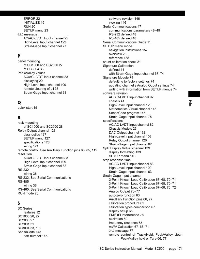
Index
ERROR 22INITIALIZE 19RUN 20SETUP menu 23
OVLD messageAC/AC-LVDT Input channel 95High-Level Input channel 122Strain-Gage Input channel 77
Ppanel mounting
of SC1000 and SC2000 27of SC3004 33
Peak/Valley valuesAC/AC-LVDT Input channel 83displaying 20High-Level Input channel 109remote clearing of all 36Strain-Gage Input channel 63
Qquick start 15
Rrack mounting
of SC1000 and SC2000 28Relay Output channel 123
diagnostics 127SETUP menu 127specifications 126wiring 124
remote control. See Auxilliary Function pins 66, 85, 112resolution
AC/AC-LVDT Input channel 83High-Level Input channel 109Strain-Gage Input channel 63
RS-232wiring 36
RS-232. See Serial CommunicationsRS-485
wiring 36RS-485. See Serial CommunicationsRUN mode 20
SSC Series
features 12SC1000 20, 27SC2000 27SC2001 31SC3004 33, 139SensoCode 143
part number 146
software revision 146viewing 146
Serial Communications 47communications parameters 48–49RS-232 defined 48RS-485 defined 48
Serial Communications Guide 11SETUP menu mode
navigation instructions 157overview 23reference 158
shunt calibration check 21Signature Calibration
defined 14with Strain-Gage Input channel 67, 74
Signature Module 74defaulting to factory settings 74updating channel’s Analog Ouput settings 74writing with information from SETUP menus 74
software revisionAC/AC-LVDT Input channel 92chassis 41High-Level Input channel 120Mathematics Virtual channel 146SensoCode program 146Strain-Gage Input channel 75
specificationsAC/AC-LVDT Input channel 82Chassis Models 26DAC Output channel 132High-Level Input channel 108Relay Output channel 126Strain-Gage Input channel 62
Split Display Virtual channel 139display formatting 139SETUP menu 140
step response timeAC/AC-LVDT Input channel 83High-Level Input channel 109Strain-Gage Input channel 63
Strain-Gage Input channel2-Point Known Load Calibration 67–68, 70–713-Point Known Load Calibration 67–68, 70–715-Point Known Load Calibration 67–68, 70, 72Analog Output 73–77auto-zero function 63Auxilliary Function pins 66, 77calibration procedure 61calibration types comparison 67display setup 65EMI/RFI interference 78excitation 69frequency response 63mV/V Calibration 67–68, 71OVLD message 77remote control of Track/Hold, Peak/Valley clear,
Peak/Valley hold or Tare 66, 77
SC Series Instruction Manual - Model SC500 page 171

resolution 63SETUP menu 63Shunt Calibration 21, 67, 69, 71software revision 75specifications 62step response time 63troubleshooting 77wiring 60
System Connectordiagnostics 41pinout 36
TTare
activating or deactivating 21remote of all channels 36See also Auxilliary Function pins.
Tare light 21troubleshooting
AC/AC-LVDT Input channel 95DAC Output channel 136
High-Level Input channel 122Strain-Gage Input channel 77
UUP button 23user values 146
VVALUE button 20
Wwiring
AC/AC-LVDT Input channel 80DAC Output channel 130High-Level Input channel 98Mathematics Virtual channel 144Relay Output channel 124Strain-Gage Input channel 60
page 172 008-0671-00

W
arranty
WarrantyHoneywell warrants goods of its manufacture as being free of defective materialsand faulty workmanship. Contact your local sales office for warranty information.If warranted goods are returned to Honeywell during the period of coverage, Hon-eywell will repair or replace without charge those items it finds defective. Theforegoing is the Buyer’s sole remedy and is in lieu of all other warranties,expressed or implied, including those of merchantability and fitness for a particularpurpose.
Specifications may change without notice. The information we supply is believedto be accurate and reliable as of this printing. However, we assume no responsi-bility for its use.
While we provide applications assistance personally, through our literature andthe Honeywell web site, it is up to the customer to determine the suitability of theproduct in the application.

Honeywell Automation and Control SolutionsSensotec Sensors2080 Arlingate LaneColumbus, Ohio 43228-4112Tel: (614)850-5000Fax: (614)850-1111E-mail: [email protected]
http://www.honeywell.com/sensotec
Document Number 008-0608-00 Printed in USA © Copyright 2005 Honeywell International Inc.