scada security: an attack tolerant...
TRANSCRIPT
SCADA Security: An Attack Tolerant Approach
Amer Atta Yaseen, Mireille Bayart
CRIStAL UMR CNRS 9189
Université Lille 1, 59655 Villeneuve d'Ascq Cedex, France
Abstract
To answer the cyber-attacks on SCADA (Supervisory
Control and Data Acquisition) systems, we wonder whether
an attack tolerant approach can be implemented. Indeed, the
most of networked control system security mechanisms are
based on detection and rejection of the cyber-attacks control
data. This rejection is easy to be detected by the attackers.
As a result, the attackers will continue to improving their
strategy in order to break down the security mechanism.
They try until they reache their goals, and generally, during
this time, there is no indication about presence of cyber-
attacks. In addition to specific algorithms such Data
Encryption Standard (DES), Message Digest (MD5),
timestamp, a new security mechanism based on the
deception for the cyber-attacks is proposed. This
mechanism, from a mathematical model of the plant, can
make that the attackers believe that he has achieved the
wished purpose, as they receive indication on their actions
within the sensor reading. As a result, the attackers stop to
improve their attack method. So, to answer the cyber-attacks
on SCADA System, an attack tolerant approach is proposed.
1. Introduction
The distributed architectures are currently implemented in
control system. Indeed the use of networks, to allow the
components to communicate in these architectures, offers a
best flexibility in design at the functional level as well as the
hardware level [1]. They are applied in a broad range of
system such as chemical plants, refineries, power plans,
electrical power grids, manufacturing plants and so on.
Depending of their applications, they can have various
names: Process Control Systems (PCS), Distributed Control
Systems (DCS), Cyber-Physical Systems CPS (for
embedded sensors and actuators networks), SCADA
(Supervisory Control and Data Acquisition) or Networked
Control Systems.
The distributed automation systems are functionally
divided into various levels. At the lowest level, the input/
output level (I /O level), the network devices are in direct
contact with the process via the sensors and the actuators,
and communicate measurement data to the control level, or
receive control signals from the control level. Specific
networks have been gradually replaced by Ethernet network.
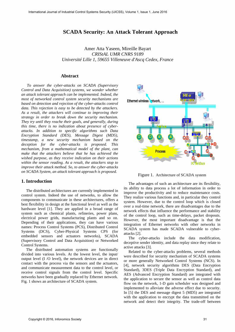
Fig. 1 shows an architecture of SCADA system.
Figure 1. Architecture of SCADA system
The advantages of such an architecture are its flexibility,
its ability to data process a lot of information in order to
improve the productivity and to reduce maintenance costs.
They realize various functions and, in particular they control
system. However, due to the control loop which is closed
over a real-time network, there are disadvantages due to the
network effects that influence the performance and stability
of the control loop, such as time-delays, packet dropouts.
However, the most important disadvantage is that the
integration of Ethernet networks with other networks in
SCADA system has made SCADA vulnerable to cyber-
attacks [2].
The cyber-attacks include the data modification,
deceptive sender identity, and data replay since they relate to
active attacks [3].
Related to the cyber-attacks problems, several methods
were described for security mechanism of SCADA systems
or more generally Networked Control Systems (NCS). In
[4], network security algorithms DES (Data Encryption
Standard), 3DES (Triple Data Encryption Standard), and
AES (Advanced Encryption Standard) are integrated with
the application to secure the sensor as well as control data
flow on the network, 1-D gain scheduler was designed and
implemented to alleviate the adverse effect due to security.
In [5] the DES and message digest 5 (MD5) are integrated
with the application to encrypt the data transmitted on the
network and detect their integrity. The trade-off between
International Journal of Industrial Control Systems Security (IJICSS), Volume 1, Issue 1, June 2016
Copyright © 2016, Infonomics Society 31

NCS security and its real-time performance was
demonstrated in [6]. A quick detection approach against
data-injection attack in the smart grid was introduced in [7].
The Named Data Networking (NDN) was used in [8] in
order to prevent the most attacks that IP-based systems are
vulnerable to. The authors in [9] design a detection module
based on implementation of DES algorithm, furthermore, to
protect NCSs from getting out of control, the authors design
also a response module. The DES was adopted in [10] as
security solutions for the DC motor networked control
system in TrueTime platform algorithm.
However, in all the mentioned methods [4]-[10], the
injected control data by the cyber-attacks can be only
detected and rejected. Therefore, the attacker will continue
to improve his strategy to break the SCADA system security
by the trial and error method. Normally, this method is based
on the monitoring ability to the actual sensor reading which
supplies by the recent security mechanisms in case of the
break of its encryption. Furthermore, the attacks control data
rejection always are done in remote plant side without any
notification in controller side. As an example, the DES key,
which is used by the most of previous researches that deals
with the security of SCADA system, this DES key publicly
has been broken in 22 hours and 15 minutes in January 1999
[11].
2. Towards attack-tolerant SCADA system
Network security can be defined as the measures and
policies adopted by a network administrator to prevent and
monitor unauthorized access, misuse, modification, or denial
of a computer network and network-accessible resources
[12]. The previous researches that are dealt with SCADA
security were tried to apply the security tools, which
designed for all types of networks. The main orientation of
these tools is the prevention but SCADA systems demand to
be real time operating and must continuously functioning.
Most of the computer security research focus on
confidentiality, so what will be happened if the prevention is
broken? The control system will receive a faulty response
and in this case, it’s a new type of fault due to the attack (we
call it "attack fault")
In this paper, we propose a fault tolerant method. It's a
data processing for the attack fault which occurs when the
cryptography is broken. This method will be named “Attack-
Tolerant”, this method is based on reconfiguration of the
sensor reading. On other hand, the proposed method will be
stopped the attack fault improving as will be described in the
next section.
3. Stopping the attack fault improvement
In general, the attacker’s algorithm can be summarized as
in Fig.2. The logical behavior of all attackers is based on the
development of a method of attacks by reading the
information sent back via the network, of a sensor of a spied
plant. The attacker will try to control the remote system: as
he receives no answer, he tries again and adopts a new
method.
Figure 2. The general attacker algorithm against the current
security mechanisms
In this paper, a new scenario for security mechanism is
given. This mechanism allows, on one hand, to delude the
attacker that he has succeeded in injection of deceptive
control data to the remote plant as new control signal instead
of original legal control signal, and on the other hand, to
prevent the attack signal to perturb the system. The method
makes that the algorithm of the aggressor becomes invisible
and weak by discontinuing the core of its development (The
block of correcting and updating in Fig.2). The Fig.3
illustrating what will be the status of attacker’s algorithm
against the proposed security mechanism.
Figure 3. The general attacker algorithm against the
proposed mechanism
Furthermore, an indication about an attempt to take the
control of the plant by unauthorized person is available in
the local controller side.
International Journal of Industrial Control Systems Security (IJICSS), Volume 1, Issue 1, June 2016
Copyright © 2016, Infonomics Society 32

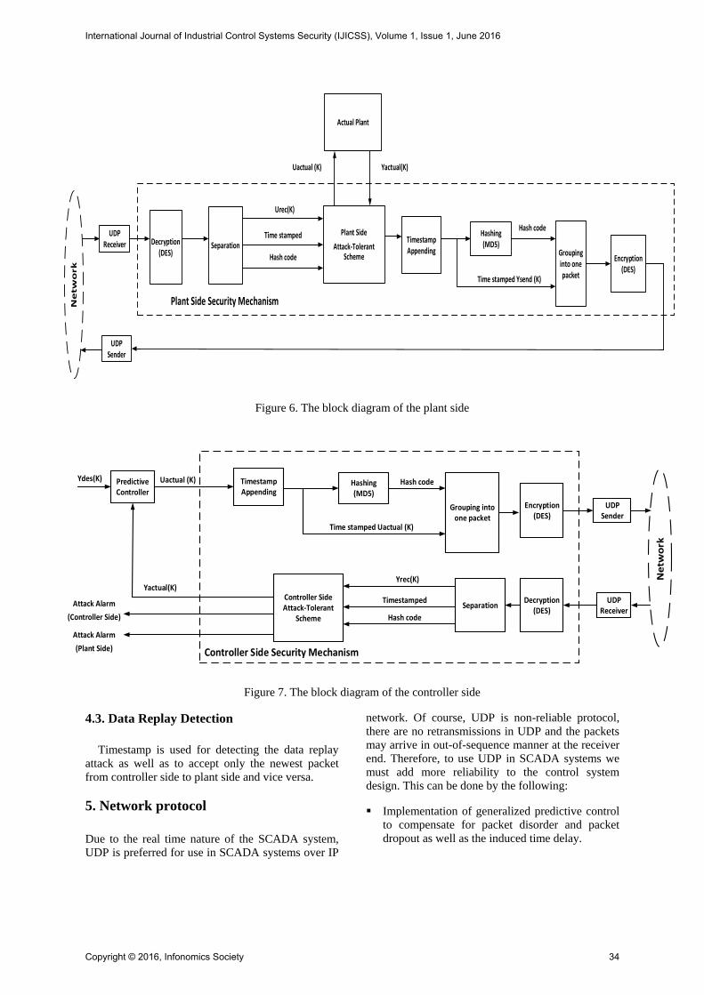
4. Common security components
Fig. 6 and Fig. 7 illustrate the complete block diagram for
the plant side and controller side of the proposed SCADA
system. There are three common security components
located in both system sides (i.e. controller & Plant); these
components can be summarized as follows:
4.1. Data confidentiality
The typical symmetric ciphers for Networked Control
System data confidentiality are DES, 3DES and AES. The
total time for encryption as well as decryption depends upon
the packet length between controller and the plant. AES
induces the greatest duration, 3DES is faster but the most
performant according to the induced time delay is DES [3].
Due to its fast speed, DES algorithm is the most commonly
used symmetric cipher. Therefore, in this paper, the DES
algorithm is choose to perform data encryption. DES
algorithm is symmetric cipher, which transforms a 64-bit
plaintext (controller or sensor data) into a 64-bit ciphertext.
Fig. 4 shows DES general structure.
Initial permutation
Round 1
Round 2
Round 16
Final permutation
Round-key generator
64-bit plaintext(Controller or Sensor Data)
K1
48-bit
K2
48-bit
K16
48-bit
64-bit ciphertext(Controller or Sensor Data)
56-bitKey
DES Algorithm
Figure 4. DES General Structure
The main process of encryption is consists of the
following four stages.
Initial permutation replacement.
Round-key generator, which generates 48-bits of key
from 56-bit key to be used in each round (sub key).
Sixteen rounds of the identical iterations, which include
permutations, substitutions and XOR operations.
In order to produce the ciphertext, the output of the last
round will be passed through a final permutation.
However, to secure data flows over the network, the used
of data encryption alone is not sufficient because, data
tampering attacks to the sensor and/or control data, for
example, cannot be prevented by the data encryption, which
can significantly impair the system performance or even lead
to loss of control of SCADA systems [12].
4.2 Data integrity
In order to checking the Integrity of the SCADA data,
one-way hash function is used. One-way hash functions
accept a variable size message as input and produce a fixed-
size output, called hash code. MD5 hashes are used to ensure
the data integrity of the received control signals at the plant
side and the received sensor signals at the controller side. An
MD5 hash is NOT encryption. It is simply a fingerprint of
the given input. However, it is a one-way transaction and as
such, it is almost impossible to reverse engineer an MD5
hash to retrieve the original string. The MD5 takes an input
of arbitrary length and produces a message digest that is
128-bits long. The MD5 algorithm initializes four 32-bit
variables (A, B, C, D). These four variables are with
predefined values at the beginning, then for each 32-bit
block of data it continually calculates the value of hash. Fig.
5 illustrates the basic operations of MD5, where, F is a
nonlinear function. M[i] denotes one message word input,
and T[i] denotes a 32-bit constant selected from a stationary
table containing 64 constants definite in the specification. S
denotes a 5-bit input that controls the left bit rotation of the
input sum. MD5 involves of 64 of these operations, gathered
in four rounds of 16 operations. After 64 basic operations,
the chaining variable is updated by immediately adding the 4
variables (A, B, C, D) with the recent content in the chaining
variable.
Because the MD5 hash algorithm always produces the
same output for the same given input. The deception attacks
(except the data replay attack) can be detected by comparing
the hash of the source data (i.e. actual controller signal or
sensor reading) with a newly created hash of the destination
side (i.e. controller side or plant side) to check that it is intact
and unmodified.
<<S
+
+
+
+
A B C D
A B C D
F
M[i]
T[i]
Figure 5. Basic operations of MD5
International Journal of Industrial Control Systems Security (IJICSS), Volume 1, Issue 1, June 2016
Copyright © 2016, Infonomics Society 33
UDPReceiver
Plant Side
Attack-Tolerant Scheme
Uactual (K) Yactual(K)
Plant Side Security Mechanism
UDPSender
Ne
tw
ork
Grouping into one packet
Timestamp Appending
Hashing(MD5)
Encryption(DES)
Time stamped Ysend (K)
Hash codeTime stamped
Hash code
Decryption(DES)
Separation
Actual Plant
Urec(K)
Figure 6. The block diagram of the plant side
PredictiveController
Controller Side Attack-Tolerant
Scheme
Ne
two
rk
UDPReceiver
UDPSender
Uactual (K)
Yactual(K)
Controller Side Security Mechanism
Ydes(K)
Grouping into one packet
Timestamp Appending
Hashing(MD5)
Encryption(DES)
Decryption(DES)
Separation
Yrec(K)
Hash code
Time stamped Uactual (K)
Hash code
TimestampedAttack Alarm
(Controller Side)
Attack Alarm
(Plant Side)
Figure 7. The block diagram of the controller side
4.3. Data Replay Detection
Timestamp is used for detecting the data replay
attack as well as to accept only the newest packet
from controller side to plant side and vice versa.
5. Network protocol
Due to the real time nature of the SCADA system,
UDP is preferred for use in SCADA systems over IP
network. Of course, UDP is non-reliable protocol,
there are no retransmissions in UDP and the packets
may arrive in out-of-sequence manner at the receiver
end. Therefore, to use UDP in SCADA systems we
must add more reliability to the control system
design. This can be done by the following:
Implementation of generalized predictive control
to compensate for packet disorder and packet
dropout as well as the induced time delay.
International Journal of Industrial Control Systems Security (IJICSS), Volume 1, Issue 1, June 2016
Copyright © 2016, Infonomics Society 34
In order to solve the problem of “out-of-
sequence“, timestamp is used to accept only the
newest packet that sent from the authorized
controller side and refusing the old one.
6. Attack-tolerant scheme
The attack-tolerant scheme is design to serve the
continuity of the SCADA works when the data
confidentiality is broken.
In additional to the attack detection, the attack-
tolerant scheme helps to making the attacker believes
that he has achieved the desired goal and as a result,
the attacker stops the attack method improvement.
Furthermore, an indication about the attacks will be
included within the sensor reading.
There are two parts of the attack-tolerant scheme;
the first part is located in the plant side and the
second one in the controller side.
6.1. Data Plant Side Attack-Tolerant Scheme
The internal diagram of “Plant Side Attack-
Tolerant Scheme” block in Fig 6 is illustrated as in
Fig. 8.
Attack Data Detection
and Separation
Plant Mathematical
Model
Sensor Reading
Formation
Uactual (K) To the
actual plant
Uattack (K)
Yactual(K) From the
actual plant
Ymodel (K)Hash code
Urec(K)
Time stamped
Y (K) To be sent
Figure 8. The internal diagram of the plant side
attack-tolerant scheme
The attack detection and separation unit receives
three inputs, Urec(k) (which represents either
authorized, or attacker control signal), timestamp and
hash code as mentioned in section 4.
Attack detection will be utilized from the
received MD5 hash codes to check the integrity as
well as the originality of the received controller
signal.
If the received signal is, original (i.e. Uactual(K))
then timestamp is used in order to prevent the control
signal from access the actual plant if it is delayed or
replied.
If there is, no integrity or replay detected, then
the received signal will be classified as an attack
control signal Uattack(K). In order to have plant
output that related to the attack control signal,
Uattack(K) will be sent to the plant mathematical
model.
In the sensor reading formation unit, the sensor
reading of the actual plant Yactual(k) will be
included in the response of plant model in a manner
that makes the attacker believes he has achieved the
desired goal.
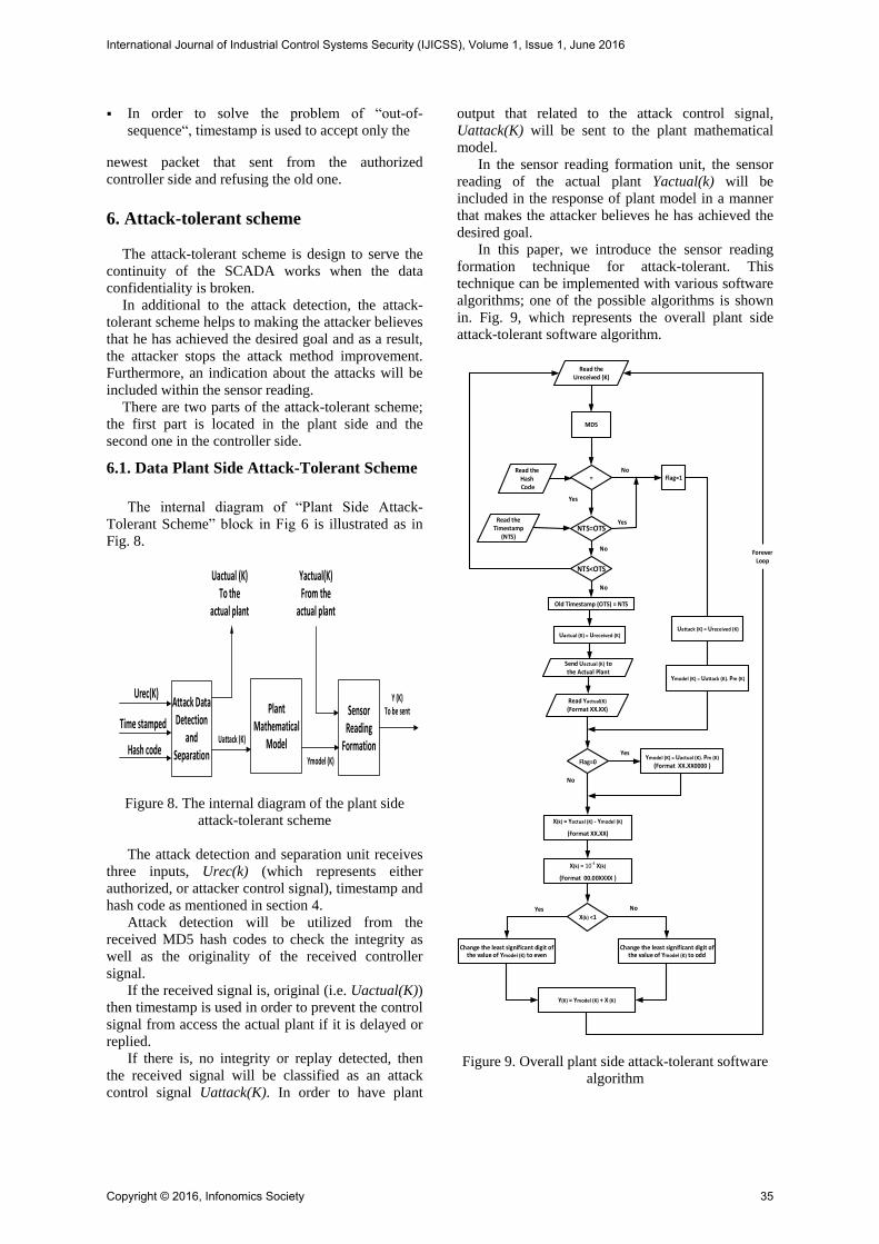
In this paper, we introduce the sensor reading
formation technique for attack-tolerant. This
technique can be implemented with various software
algorithms; one of the possible algorithms is shown
in. Fig. 9, which represents the overall plant side
attack-tolerant software algorithm.
Uactual (K) = Ureceived (K)
Send Uactual (K) to the Actual Plant
Read Yactual(K)
(Format XX.XX)
Flag=0
X(k) = Yactual (K) - Ymodel (K)
(Format XX.XX)
X(k) = 10-4 X(k)
(Format 00.00XXXX )
X(k) <1
Yes
No
Ymodel (K) = Uactual (K). Pm (K)
(Format XX.XX0000 )
Change the least significant digit of the value of Ymodel (K) to even
Change the least significant digit of the value of Ymodel (K) to odd
Yes No
Y(K) = Ymodel (K) + X (K)
Ymodel (K) = Uattack (K). Pm (K)
Flag=1
Uattack (K) = Ureceived (K)
Yes
MD5
Read the Hash Code
Read the Ureceived (K)
Read the Timestamp
(NTS)
=
NTS=OTS
Old Timestamp (OTS) = NTS
No
No
Yes
ForeverLoop
NTS<OTS
No
Figure 9. Overall plant side attack-tolerant software
algorithm
International Journal of Industrial Control Systems Security (IJICSS), Volume 1, Issue 1, June 2016
Copyright © 2016, Infonomics Society 35
Referring to Fig. 9, let X(k) is the different
between the actual sensor reading and the plant
model response or X(k) = Yactual(K) - Ymodel(K).
The absolute value of X(k) will be “Y3 Y2 . Y1 Y0” .
The value of Ymodel (K) will be “Y7 Y6 . Y5 Y4”.
If X(k) is positive then Y4 will be odd and vice
versa. The final string of the sensor reading Y(K) will
be as follows
“Y7 Y6 . Y5 Y4 Y3 Y2 Y1 Y0”
The uncertainty in actual plant is employed to
increase the level of the lack in understanding the
actual sensor reading.
6.2 Controller Side attack-Tolerant Scheme
At controller side, a timestamp will be appended
to the generalized predictive control output
Uactual(K), the Message Digest 5 (MD5) is used to
generating the hash code of the Uactual(K).
Uactual(K), hash code, and timestamp as a whole
are encrypted into one packet and sent to the plant
side.
The “Controller side Attack-Tolerant Scheme” block
in Fig. 7 performers the following procedures:
To control side attack detection and rejection.
To extract the actual sensor reading.
To detect if there is a plant side attack by
checking the received sensor reading formation.
The controller side attack-tolerant scheme
receives three inputs, the Yrec(k) which represents
either authorized or attacker sensor reading,
timestamp and hash code.
The first procedure is similar to the procedure in the
plant side but in controller side, there is only
rejection for unauthorized and replied data.
If there is any attack in the plant side that not
detected during first procedure, the sensor reading
that provided from first procedure will be included
with this attack information.
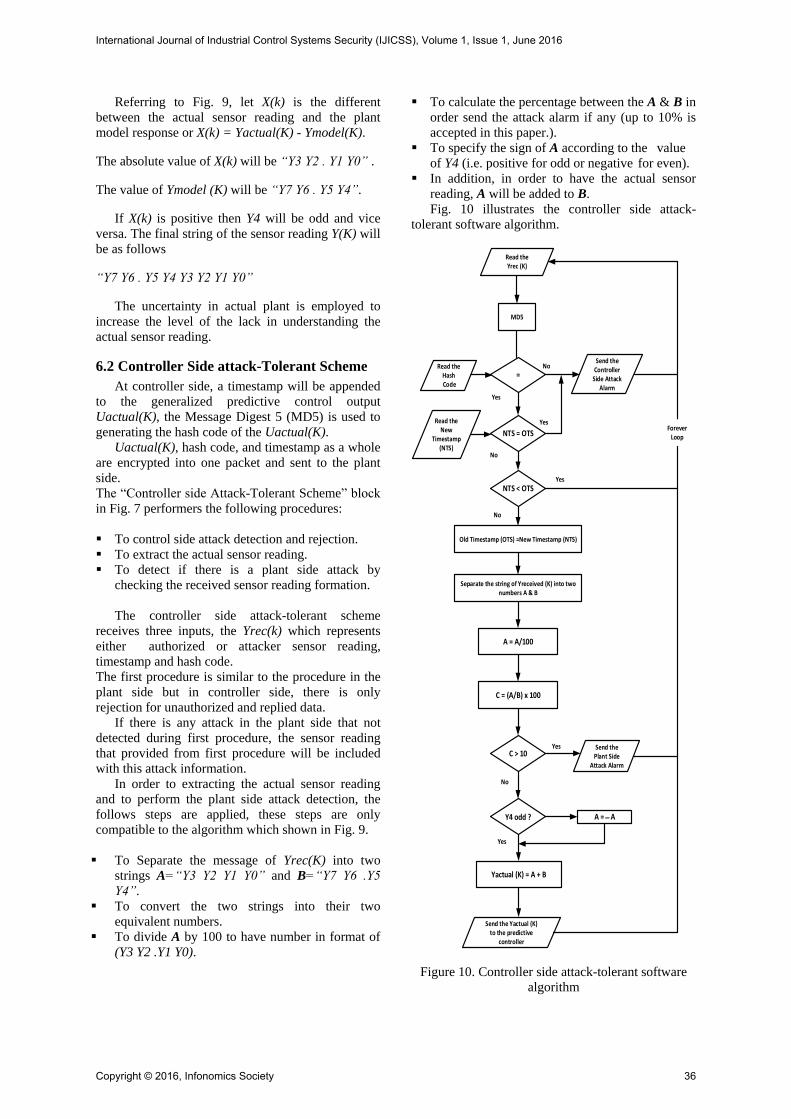
In order to extracting the actual sensor reading
and to perform the plant side attack detection, the
follows steps are applied, these steps are only
compatible to the algorithm which shown in Fig. 9.
To Separate the message of Yrec(K) into two
strings A=“Y3 Y2 Y1 Y0” and B=“Y7 Y6 .Y5
Y4”.
To convert the two strings into their two
equivalent numbers.
To divide A by 100 to have number in format of
(Y3 Y2 .Y1 Y0).
To calculate the percentage between the A & B in
order send the attack alarm if any (up to 10% is
accepted in this paper.).
To specify the sign of A according to the value
of Y4 (i.e. positive for odd or negative for even).
In addition, in order to have the actual sensor
reading, A will be added to B.
Fig. 10 illustrates the controller side attack-
tolerant software algorithm.
Separate the string of Yreceived (K) into two numbers A & B
Yes
No
No
MD5
Read the Hash Code
Read the Yrec (K)
Read the New
Timestamp(NTS)
=
NTS = OTS
Yes
No
Yes
ForeverLoop
Send the Controller
Side Attack Alarm
Old Timestamp (OTS) =New Timestamp (NTS)
NTS < OTS
A = A/100
C = (A/B) x 100
Yactual (K) = A + B
C > 10Send the
Plant Side Attack Alarm
Send the Yactual (K) to the predictive
controller
No
Yes
Y4 odd ?
Yes
A = � A
Figure 10. Controller side attack-tolerant software
algorithm
International Journal of Industrial Control Systems Security (IJICSS), Volume 1, Issue 1, June 2016
Copyright © 2016, Infonomics Society 36

7. Predictive controller
Generalized Predictive Control (GPC) has been
used in several industrial applications [13]. GPC is
used due to its ability to manage with the instability
and uncertain which introduced by unknown time
delay and data packet loss.
The GPC strategy that used in this paper was
described in [14] and can be summarized as follows:
In GPC, the plant model of the form CARIMA is:
(1)
where, Uactual(k) and Yactual(k) are the control
input and output, respectively. A(z-1), B(z-1) and
C(z-1) are polynomials. It is assumed that e(k) is a
zero mean white noise giving, C(z-1)=Imxm and
∆=1-z-1 is the differencing operator. The quadratic
cost function of GPC is:
(2)
Where H1, H2 and Hu are the minimum,
maximum prediction horizons and control horizon,
respectively. Yactual* (k+j│k) is the j step ahead
output prediction at time instant k and Ydes(k+j) are
the future desired trajectories. R and Q are the
weighting matrices. Combining (1) with the
Diophantine equation and then the optimal control
sequences can be obtained by applying matrix
algebraic manipulations:
Where, G,Q,R,F are matrices, details of them can be
found in [15]. All the elements of ∆Uactual are
computed and transmitted over the network to the
remote actual plants and then are used to compensate
for the delayed and lost packets of the controller and
sensor signals.
8. Simulation results The proposed security mechanism for SCADA
systems is developed as per the scheme mentioned
above with MATLAB. Position control of networked
DC servomotor is selected for testing and for
verifying the performance of the designed system.
The parameters and values chosen for motor
modeling are as shown in Table 1 [16].
Initially, the system is tested without any attack;
the test result is illustrated in Fig.11. After that, the
simulation is carried out by injecting of external
attack control signals Uattack(K) to the proposed
secure control systems. The Uattack(K) is
represented by pulses with random values of
amplitude (between -1 to 1). At the first time, the
rate of attack signal is selected to be 25% data
modification attacks as in Fig.12 and after that, it is
increased to 75% as in Fig.13.
Table 1. DC servomotor parameters
Parameter Abbrev Value
Moment of inertia Jm 0.000052 Kg.m2
Friction coefficient Bm 0.01 N.ms
Back EMF constant Kb 0.235 V/rad S-1
Torque constant Ka 0.235 Nm/A
Electric resistance Ra 2 Ohm
Electric inductance La 0.23 H
Figure 11. Position control over the secure SCADA
1)Uactual(k )B( Yactual(k) )A( -ZZ 1-1-
)e( )C(1
KZ 1-
H 2
H 1j
2
R
)jk(Ydes)kjk(Yactual)H ,H ,HV( u21
(3) )FYdes(RG]QGG[UactualT
T1
...1)Uactual(kUactual(k)[UactualTT
(4) ]1)-HuUactual(k...TT
H u
1j
2
Q)1jk(Uactual
International Journal of Industrial Control Systems Security (IJICSS), Volume 1, Issue 1, June 2016
Copyright © 2016, Infonomics Society 37

system without attacks (a) Actual system response
(b) The received sensor signal (Yrec)
Figure 12. Position control over the secure SCADA
system with 25% attacks (a) Attack control signal (b)
Actual response and the response to the attacker
Actually, the security mechanism maintains the
normal response of the position control system
(green lines in Fig.12(b) and Fig.13(b)).
However, the sensor reading ‘Yrec’ (red lines in
Fig.12(b) and Fig.13(b)) is follows what should be
the remote plant response to the attacker signal
‘Uattack’.
9. Conclusion
In this paper, to answer to cyber-attacks on
SCAD systems, an attack-tolerant scheme is
introduced. The proposed method is based on
deception of the cyber-attack when the current
available data encryption method is broken.
Figure 13. Position control over the secure SCADA
system with 75% attacks (a) Attack control signal (b)
Actual response and the response to the attacker
In additional to the continuity of the control system
work, the proposed technique makes the attacker to
stop the development of the attack method, to send
attack alarm to controller side. This information
allows to give time for the authorized person to
repair the broken part in the security mechanism.
In order to introduce the proposed technique, simple
algorithm for sensor reading formation is described.
This method can be extended to be more complex
depending on the type of control system application.
The investigation reveals that the proposed security
mechanism can successfully be used for SCADA
systems.
International Journal of Industrial Control Systems Security (IJICSS), Volume 1, Issue 1, June 2016
Copyright © 2016, Infonomics Society 38
10. References
[1] M. Bayart, Distribution diagnosis of networked
embedded system, 17 th IFAC World Congress, Seoul, Korea, 2008, pp.6827 – 6832
[2] Y. Qiao, G. P. Liu, G. Zheng, and W. Hu, “NCSLab: A Web-based global-scale control laboratory with rich interactive features,” IEEE Trans. Ind. Electron., vol. 57, no. 10, pp. 3253–3265, Oct. 2010.
[3] W. Stallings, Cryptography and Network Security: Principles and Practice, 4th ed. Englewood Cliffs, NJ: Pearson/Prentice-Hall, 2006.
[4] Gupta, R.A.; Mo-Yuen Chow, "Performance assessment and compensation for secure networked control systems,” 34th Annual Conference of IEEE Industrial Electronics (IECON 2008), Orlando, Florid, pp.2929-2934, 10-13 Nov. 2008
[5] Pang Zhong hua; Liu Guoping, "Secure networked control systems under data integrity attacks,” 29th Chinese Control Conference (CCC), Beijing, China, pp.5765-5771, 29-31 July 2010
[6] Wente Zeng; Mo-Yuen Chow, "A trade-off model for performance and security in secured Networked Control Systems," 2011 IEEE International Symposium on Industrial Electronics (ISIE), Gdansk, Poland, pp. 1997- 2002, 27-30 June 2011.
[7] Shuguang Cui; Zhu Han; Kar, S.; Kim, T.T.; Poor, H.V.; Tajer, A., "Coordinated data-injection attack and detection in the smart grid: A detailed look at enriching detection solutions,"IEEE Signal Processing Magazine, vol.29, no.5, pp. 106-115, Sept. 2012
[8] Perez, V.; Garip, M.T.; Lam, S.; Lixia Zhang, "Security evaluation of a control system using Named Data Networking," 21st IEEE International Conference on Network Protocols (ICNP), Goettingen, Germany, pp.1-6, 7-10 Oct. 2013
[9] Zhang Liying; Xie Lun; Li Weize; Wang Zhiliang, "A secure mechanism for networked control systems based on TrueTime," International Conference on Cyberspace Technology (CCT 2013), Beijing, China, pp.44-49, 23-23 Nov. 2013.
[10] Liying Zhang, Lun Xie, Weize Li, Zhiliang Wang,"Security Solutions for Networked Control Systems Based on DES Algorithm and Improved Grey Prediction Model", IJCNIS, vol.6, no.1, pp.78-85, 2014.
[11] Fedora Documentation Project, "Fedora 13 Security Guide", Fultus Corporation, July 12, 2010.
[12] Simmonds, A; Sandilands, P; van Ekert, L "An Ontology for Network Security Attacks". Lecture Notes in Computer Science, 2004.
[13] E.F.Camacho,C.Bordons,"Model predictive control", Springer, London, 1999.
[14] Kunjie Li; Liu, G.P., "A Simplified GPC Algorithm of Networked Control Systems," 2007 IEEE International Conference on Networking, Sensing and Control, London, UK, pp.58-63, 15-17 April 2007.
[15] Rossiter, J. A., “Model-Based Predictive Control: A Practical Approach”, CRC Press, 2003.
[16] Munadi; Akbar, M.A., "Simulation of fuzzy logic control for DC servo motor using Arduino based on MATLAB/Simulink," 2014 International Conference on Intelligent Autonomous Agents, Networks and Systems,pp.42-46, 19-21 Aug. 2014.
International Journal of Industrial Control Systems Security (IJICSS), Volume 1, Issue 1, June 2016
Copyright © 2016, Infonomics Society 39