scan for more information t echnical support sheet rawe ... · now that the rawe stonebox is...
TRANSCRIPT

Fig. 1 Parts setup
C
AB
B
D
E
Disclaimer: This document should be reviewed by supervisory personnel prior to commencing any Hypond Effluent Storage System installation. While every effort has been made to ensure that the information in this document is correct and accurate, users of Hynds product or information within this document must make their own assessment of suitability for their particular application. Product dimensions are nominal only, and should be verified if critical to a particular installation.
1. Parts needed for assembly
The base (A).
Note: The base panel has double longitudinal bars and single transverse bars. The single bars must be on the top side of the base for assembly.
2 x sides (B) on the left and right in the photo (with the “Z” feet).
Note: Take notice of the alignment of the sides to the narrow side spaces in the base.
2 x ends (C) on the top and bottom in the photo with the hook feet.
4 x crossbeams (D).
To assist you with your insitu assembly and installation of the RAWE Stonebox componentry, please follow the assembly process for the 1000mm long x 1000mm wide x 500mm tall RAWE Stonebox, depicted in the example below:
Technical Support Sheet
Rawe Stonebox Assembly guide
Rawe Stonebox Assembly Guide.
Scan for more information

A
A
B
B
Outer single bar
BA
C
Fig. 4 “Z” Feet Closeup
A
B
Outer single bar
B
Fig. 2 Sides intersection to the base
Fig. 3 “Z” Feet Closeup
Fig. 5 Outer hook fitted
Fig. 6 Base side view
2. Assemble the sides
”Z” Feet Close up 1 and 2
Insert the sides (B) with the “Z” feet under the outermost base wire into the base (A).
Note: Some RAWE Stonebox sizes do not allow you to insert the same number of “Z” feet into each aperture of the base. For example with the 1000mm long x 1000mm wide x 500mm tall RAWE Stonebox (shown right), only 3 x “Z” feet can be inserted in one end aperture, and 4 x “Z” feet in all the other apertures. However, make sure that whatever you do on one side, the same is done for the matching side of the base, otherwise the RAWE Stonebox will be assembled “out of square”.
2.1 “Z” Feet Closeup 2
The close up 1 shows the “Z” feet at one end of the base, where 3 x “Z” feet are inserted. Then 4 x “Z” feet will fit into each remaining aperture (close up 2).
3. insert hook feet ends
Insert the ends (with the hook feet) under and into the base.
Note: The outer hook feet may need to be squeezed together to fit into the outer aperture.
Prior to raise the sides (step 4), make sure that the base (A) is laid with the outer single bar in the elevated position. This allows for the hooked feet on the ends to be fitted.
RA
WE
STo
nE
Bo
x A
SS
Em
Bly
gu
iDE
_ | D
RA
inA
gE
| P
g 2
BB
B
C
C
D
C
C
B A
Fig. 7 Sides raising
Fig. 8 Crossbeams
Fig. 9 Crossbeams hooked over the bars
Fig. 10 Stonebox filling at Hynds Pukekohe Factory
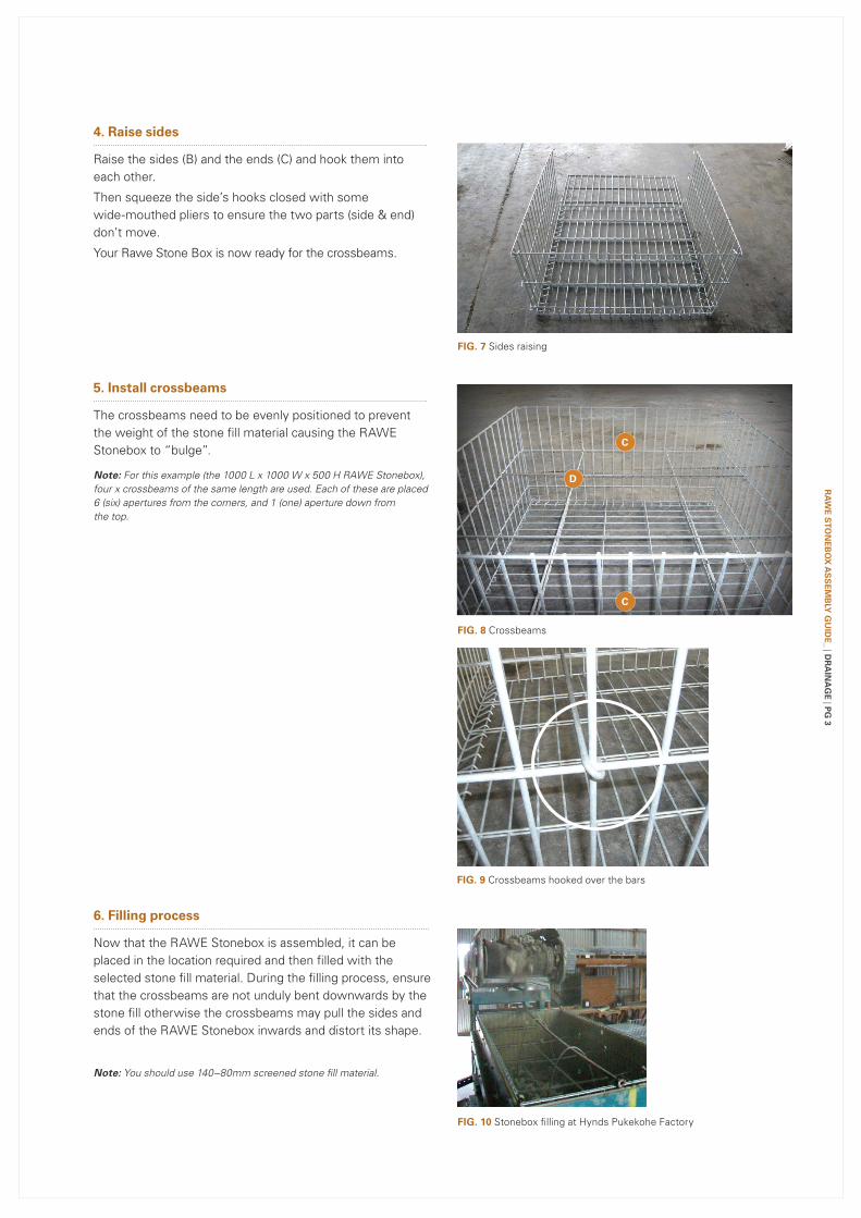
4. Raise sides
Raise the sides (B) and the ends (C) and hook them into each other.
Then squeeze the side’s hooks closed with some wide-mouthed pliers to ensure the two parts (side & end) don’t move.
Your Rawe Stone Box is now ready for the crossbeams.
5. install crossbeams
The crossbeams need to be evenly positioned to prevent the weight of the stone fill material causing the RAWE Stonebox to “bulge”.
Note: For this example (the 1000 L x 1000 W x 500 H RAWE Stonebox), four x crossbeams of the same length are used. Each of these are placed 6 (six) apertures from the corners, and 1 (one) aperture down from the top.
6. Filling process
Now that the RAWE Stonebox is assembled, it can be placed in the location required and then filled with the selected stone fill material. During the filling process, ensure that the crossbeams are not unduly bent downwards by the stone fill otherwise the crossbeams may pull the sides and ends of the RAWE Stonebox inwards and distort its shape.
Note: You should use 140–80mm screened stone fill material.
RA
WE
STo
nE
Bo
x A
SS
Em
Bly
gu
iDE
_ | DR
Ain
Ag
E | P
g 3

E
Fig. 11 Lid installation
Fig. 12 Final assembly
Disclaimer: This document should be reviewed by supervisory personnel prior to commencing any Hypond Effluent Storage System installation. While every effort has been made to ensure that the information in this document is correct and accurate, users of Hynds product or information within this document must make their own assessment of suitability for their particular application. Product dimensions are nominal only, and should be verified if critical to a particular installation.
7. install the lid
Once filled, the RAWE Stonebox lid is then attached.
Note: The lid does not have double longitudinal bars. Position the Lid on the top of the Rawe Stonebox and use wide-mouthed pliers to close the ‘C’ clamp rings around the lid and sides/ends at regularly spaced intervals.
8. Fully Assembled RAWE Stonebox
Branches Nationwide Support Office & Technical Services 09 274 0316