scatter of high frequency electromagnetic wave on the trihedral
TRANSCRIPT
PRZEGLĄD ELEKTROTECHNICZNY (Electrical Review), ISSN 0033-2097, R. 87 NR 12b/2011 5
Stanisław APANASEWICZ, Stanisław PAWŁOWSKI, Jolanta PLEWAKO
Rzeszow University of Technology
Scatter of high frequency electromagnetic wave on the trihedral conductive corner
Abstract. The paper presented the results of numerical studies of high frequency electromagnetic wave scattering on the trihedral corner of the homogeneous and isotropic conductive body of linear properties. The paper considered the impact of non-magnetic (Al) and magnetic (Fe) body on the distributions of electromagnetic field. A plan electromagnetic wave of high frequency (10 GHz) of parallel polarization to one edge of the corner constitutes a exciting field. Iterative-boundary method of fundamental solutions has been used for the analysis of the issue. Streszczenie. W pracy zaprezentowano rezultaty badań numerycznych zagadnienia rozproszenia fali elektromagnetycznej wysokiej częstotliwości na trójściennym narożu jednorodnego i izotropowego ciała przewodzącego o liniowych właściwościach. Zbadano różnice we wpływie ciała niemagnetycznego (Al) i magnetycznego (Fe) na rozkłady pola elektromagnetycznego. Pole wzbudzające stanowi płaska fala elektromagnetyczna wysokiej częstotliwości (10 GHz) o polaryzacji równoległej do jednej z krawędzi naroża. Do analizy zagadnienia zastosowano iteracyjno-brzegową metodę rozwiązań fundamentalnych.(Rozpraszanie fali elektromagnetycznej wysokiej częstotliwości na trójściennym narożu przewodzącym) Słowa kluczowe: naroże przewodzące, fale elektromagnetyczne, metoda rozwiązań fundamentalnych Keywords: conducting corner, electromagnetic waves, fundamental solutions method Introduction
Structure elements of electrical equipment usually include edges and corners which are fragments of a surface of a very large curvature. The functions of electromagnetic field near such surfaces can reach high values and are usually non regular (experience large changes over very short distances). Inclusion of these effects with numerical analysis is very troublesome, because it involves the necessity of a strong density of a local discretization mesh, which leads to a radical increase numerical model of the problem. In this situation, a fairly common practice is to ignore the physical effects occurring near the edges and corners (mismatch of discretization mesh to the variability of function of the field, an incorrect representation of boundary conditions on their surfaces, etc.), which is usually the cause of large errors of local solutions, and can even wake doubts about the correctness of the solution in the rest of the system analyzed. The aim of the authors of this paper is to examine through analytical considerations and numerical simulations of physical effects in the vicinity of edges and corners of conductive bodies interacting with an external electromagnetic field. Another aim is to assess the extent to which ignoring of these effects may affect the accuracy of the solution in more remote parts of the area analyzed. Previous studies of the authors concerned mainly 2D issues (i.e., edges) for low and high frequency [1-9]. In the paper [10] the results of numerical simulations in the 3D system for trihedral corner of conductive body (Fig. 1) working with harmonic electromagnetic field of low frequency (50 Hz) have been presented. This paper is a continuation of previous research, its purpose is to analyze the field distribution of high frequency electromagnetic wave (10 GHz) scattered on the trihedral corner of the conductive body of weak and strong magnetic properties. To solve the formulated problem iterative-boundary numerical method described in [4] was used. It has also been used in [7, 10].
Formulation of the problems
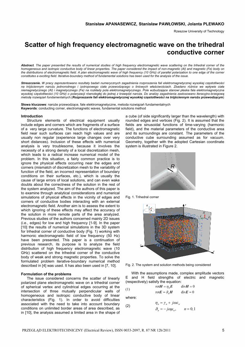
The issue considered concerns the scatter of linearly polarized plane electromagnetic wave on a trihedral corner of spherical vertex and cylindrical edges occurring at the intersection of three mutually perpendicular walls of homogeneous and isotropic conductive body of linear characteristics (Fig. 1). In order to avoid difficulties associated with the need to take into account boundary conditions on unlimited border areas of area described, as in [10], the analysis assumed a limited area in the shape of
a cube (of side significantly larger than the wavelength) with rounded edges and vertices (Fig. 2). It is assumed that the fields are sinusoidal functions of time-varying (harmonic field), and the material parameters of the conductive area and its surroundings are constant. The parameters of the conductive cube surrounding assumed as for vacuum. Geometry, together with the adopted Cartesian coordinate system is illustrated in Figure 2.
Fig. 1. Trihedral corner
Fig. 2. The system and solution methods being considered
With the assumptions made, complex amplitude vectors E and H field strengths of electric and magnetic (respectively) satisfy the equation:
(1) 0div rot
0div rot
EHE
HEH
n
n
where:
(2) 1 0 , ,nj
j
nn
nnn

6 PRZEGLĄD ELEKTROTECHNICZNY (Electrical Review), ISSN 0033-2097, R. 87 NR 12b/2011
- conductivity, - permittivity, - magnetic permeability, n - number of area: n = 0 - body scattering surrounding , n = 1 - inside the scattering body
On the boundary surface of the vectors E and H satisfy the classical boundary conditions of electrodynamics, which can be written as: (3) II
||I||
II||
I|| , EEHH
(4) II1
I0
II1
I0 , EEHH
where the symbols || i represent (respectively) the tangent and normal component of the field to the boundary area, the upper index I refers to a field component outside of the cube, II - from the inside.
The method of solution
To solve the problem the iterative-boundary numerical method described in detail in [4] (see also [7.10]) was used. It consists in approximating of searching function of the induced field using linear combination of fundamental solutions of equations (1). These solutions can be interpreted as a superposition of fields emitted by the two types of antennas - an infinitely short dipole antenna (Hertz dipole) in the center of any conductivity and infinitesimal loop antenna situated in the same point, called a fictitious source (see Figure 2). These points, which are singularities of fundamental solutions, are selected randomly in successive iterative steps outside the area covered by the solution. Approximate sum coefficients are calculated in a way to minimize the functional boundary error value of the solution. This allows each of iterative steps to obtain the best possible fulfilment of boundary conditions (in terms of average square norm). Iteration is carried out until the desired functional boundary error value. Iterative-boundary character drastically reduces the size of the numerical model and calculation time and allows to avoid the need to artificially limit the open areas found in the system analyzed (here - the space surrounding the cube). Solution of the problem were obtained using a copyright program called Duo [4]. System parameters adopted for numerical simulation Excitive field in the presented system is a plane electromagnetic wave propagating in a vacuum in the direction of the 0X-axis with polarization parallel to the 0Y-axis (Fig. 2) described by dependencies:
(5) 0,,0 00tkxjeE E , tkxjeH 00 ,0,0H
where 2k , f 2
and with the following parameters: amplitude of the electric field intensity: E0 = 1kV/m, amplitude of the magnetic field intensity: H0 = 2,65 A/m, frequency: f = 10 GHz wavelength: cm 3 cf
Scattering body is a cube shaped with rounded corners and edges (see figure 2) of dimensions:: cube edge length: a = 8 cm, radius of edges and vertex: R = 5 mm Two kinds of scattering parameters of the body material were adopted - such as for aluminum Al = 27 MS/m rAl =1 as well as for structural steel (in the linear approximation)::
Fe= 6,9 MS/m, r Fe = 400 For the surrounding of the scattering body the material parameters were assumed as for the vacuum. The results of calculations The results of calculations are presented in graphs in Figure 3 – Figure 9. Figure 3 illustrates the plane wave scatter on high-frequency conductive body in the shape of a cube with rounded edges and vertices. It shows the calculated distribution of instantaneous values of the magnetic field Hz component in the plane z = 0. It illustrates the reflection and diffraction phenomena and the effect of "shadow" extending in the direction of the incident wave. Fig. 3. Distribution of the instantaneous values of Hz Graphs in Figure 4 - 9 show the distributions of amplitudes of the Cartesian components of electric and magnetic field in the plane x = y passing through one of the four vertices of the cube wall facing incident wave.
Fig. 4. Distributions of the amplitude of the electric field component Ex in the plane x = y, - distance from the axis OZ. Comparison for conductive bodies: non-magnetic (Al) and magnetic (Fe)

PRZEGLĄD ELEKTROTECHNICZNY (Electrical Review), ISSN 0033-2097, R. 87 NR 12b/2011 7
Fig. 7. Distributions of the amplitude of the magnetic field component Hx in the plane x = y, - distance from the axis OZ. Comparison for conductive bodies: non-magnetic (Al) and magnetic (Fe)
Fig. 5. Distributions of the amplitude of the electric field component Ey in the plane x = y, - distance from the axis OZ. Comparison for conductive bodies: non-magnetic (Al) and magnetic (Fe)
Fig. 6. Distributions of the amplitude of the electric field component Ez in the plane x = y, - distance from the axis OZ. Comparison for conductive bodies: non-magnetic (Al) and magnetic (Fe)
Fig. 8. Distributions of the amplitude of the magnetic field component Hy in the plane x = y, - distance from the axis OZ. Comparison for conductive bodies: non-magnetic (Al) and magnetic (Fe)

8 PRZEGLĄD ELEKTROTECHNICZNY (Electrical Review), ISSN 0033-2097, R. 87 NR 12b/2011
From the results of calculations presented in figures (4-6) it shows, that the distributed components appear Ex, Ez absent in the electric field of the incident wave field, showing the influence of the conductive body to change polarization of the reflected wave.
The presented components of the electric field distributions for non-magnetic and magnetic body allow to observe a strong field concentration near the top corners of the magnetic body (especially the component Ex). Influence of vertex corners of non-magnetic body is not so significant. A similar effect is observed near the edge of the corners (Fig. 5).
Like for the electric field, the presence of the magnetic field components (Hx, Hy) (non present in the incident wave field) is observed. In the case of the magnetic field component significant differences in the values of the fields at the vertex corners of non-magnetic and magnetic bodies are not observed. A significant change concerns the edge of the corner - is observed, in contrast to the electric field component of a much larger value of Hz for non-magnetic body than for the magnetic body. Summary The paper presents results of numerical studies of high frequency electromagnetic wave on trihedral homogeneous and isotropic corner of the conductive body of linear properties. The differences in the impact of non-magnetic (Al) and magnetic (Fe) body on the distributions of electromagnetic field were examined.
The results of the tests carried out permit to draw the following conclusions: 1. In the vicinity of the corners and edges of the conductive bodies the electromagnetic field functions become less regular (they experience big changes at short distances). 2. As a result of electromagnetic wave interaction with the conductive body the field components which do not appear in the original field are observed. The largest amplitudes of these components are presented on the surfaces of the edge corners (fig (Ez, Hx, Hy)) or on the surface of its vertex (Ex, Ez). 3. The essential differences in the distributions of the fields in the vicinity of the non-magnetic and magnetic corners are observed. Special attention is put on a large component of the value of Ex and on a rapid change of Ey component at the surface of the magnetic corner vertex (Fig. (Ex, Ey))
REFERENCES [1] Apanasewicz S., Paw łowsk i S.: Algorytm obliczania pola
elektromagnetycznego w masywnej ścianie z narożem, Przegląd Elektrotechniczny, (2002), nr 12.
[2] Paw łowsk i S.: Application of the Boundary - Approximated Method for the Analysis of Electromagnetic Field Nearby Conducting Corner, ISEF 2003 - XI International Symposium on Electromagnetic Fields - Maribor, Slovenia, (2003), No. 2, 529 – 534.
[3] Apanasewicz S., Paw łowsk i S.: Study of Electromagnetic Field Properties in the Nieghbourhood of the Metallic Corners, Studies in Applied Electromagnetics and Mechanics, Advanced Computer Techniques in Applied Electromagnetics , IOS Press, 30 (2008), 8-15.
[4] Paw łowsk i S.: Iteracyjno-brzegowa metoda analizy trójwymiarowych zagadnień quasi-stacjonarnych zagadnień elektrodynamiki, Oficyna Wydawnicza Politechniki Rzeszowskiej, Rzeszów, (2009)
[5] Apanasewicz S., Paw łowsk i S., P lewako J.: The studium of the sinusoidal electromagnetic field in a bar of elliptical section, Proceedings of ISEF'09, (2009), 15-16.
[6] Apanasewicz S., Paw łowsk i S., P lewako J.: The studium of the flat waves’ diffraction on the sharp corner, Proceedings of ISEF'09, Arras, France, (2009), 17-18.
[7] Paw łowsk i S., P lewako J .: Application of iterative boundary method in determination of 3D harmonic electromagnetic field induced by current ducts. Przegląd Elektrotechniczny, (2010), nr 12, 109-112.
[8] Apanasewicz S., Paw łowsk i S., P lewako J.: The Study of the Sinusoidal Electromagnetic Field in a bar of elliptical cross-section, Studies in Applied Electromagnetics and Mechanics, IOS Press, (2010), 113-122.
[9] Apanasewicz S., Paw łowsk i S., P lewako J.: The studium of the flat waves’ diffraction on the sharp corner, Przegląd Elektrotechniczny, (2010), No. 5, 87-90.
[10] Paw łowsk i S . , P lewako J .: Analiza quasi-stacjonarnego pola elektromagnetycznego w sąsiedztwie trójwymiarowego naroża obszaru przewodzącego. Przegląd Elektrotechniczny, (2011), nr 8, 96-101.
Authors: prof. dr Stanisław Apanasewicz, Katedra Elektrodynamiki i Układów Elektromaszynowych, ul. W. Pola 2, 35-959 Rzeszów, E-mail: [email protected], dr hab. Stanisław Pawłowski, Katedra Elektrodynamiki i Układów Elektromaszynowych, ul. W. Pola 2, 35-959 Rzeszów, E-mail: [email protected],, dr inż. Jolanta Plewako, Katedra Energoelektroniki i Elektroenergetyki, ul. W. Pola 2, 35-959 Rzeszów, E-mail: [email protected], .
Fig. 9. Distributions of the amplitude of the magnetic field component Hz in the plane x = y, - distance from the axis OZ. Comparison for conductive bodies: non-magnetic (Al) and magnetic (Fe)