schedule 7-1 keeyask project description - manitoba hydro ...€¦ · description of the keeyask...
TRANSCRIPT

SCHEDULE 7-1
KEEYASK PROJECT
PROJECT DESCRIPTION
693588v14

SCHEDULE 7-1
DESCRIPTION OF THE KEEYASK PROJECT
TABLE OF CONTENTS
1. LIST OF FIGURES..................................................................................................................1
2. GLOSSARY ............................................................................................................................2
3. OVERVIEW OF THE KEEYASK PROJECT.......................................................................10
4. DESCRIPTION OF EXISTING PHYSICAL ENVIRONMENT .........................................12 4.1 PHYSICAL GEOGRAPHY AND GEOLOGY ......................................................................... 12 4.2 WATER REGIME ............................................................................................................. 12
4.2.1 River Hydraulics ................................................................................................... 12 4.2.2 River Flow ............................................................................................................ 13
5. KEEYASK GENERATING STATION COMPONENTS AND KEY PARAMETERS......14 5.1 PLANNING AND DESIGN PARAMETERS ........................................................................... 14
5.1.1 Datum.................................................................................................................... 14 5.1.2 Water Levels ......................................................................................................... 14 5.1.3 Reservoir Area, Forebay Levels and Powerhouse Discharge Capacity................ 14 5.1.4 Power .................................................................................................................... 14 5.1.5 Design Floods ....................................................................................................... 15
5.2 PRINCIPAL STRUCTURES ....................................................................................... 16 5.2.1 Concrete Structures............................................................................................... 16 5.2.2 Earth Structures..................................................................................................... 17
5.3 SUPPORTING INFRASTRUCTURE ..................................................................................... 18 5.3.1 Temporary Access Roads ..................................................................................... 19 5.3.2 Permanent Access Roads ...................................................................................... 19 5.3.3 Construction Camps.............................................................................................. 19 5.3.4 Potential Camp Extension..................................................................................... 20 5.3.5 Communications ................................................................................................... 20 5.3.6 Cofferdams............................................................................................................ 20 5.3.7 Ice Boom............................................................................................................... 21 5.3.8 Hydro and Contractor Work Areas ....................................................................... 21 5.3.9 Construction Power............................................................................................... 21 5.3.10 Material Sources and Borrow Areas ..................................................................... 21 5.3.11 Material Transportation, Rail Siding and Off -Loading Facility .......................... 22
5.4 CONSTRUCTION SCHEDULE............................................................................................ 22 5.5 CONSTRUCTION WORKFORCE ........................................................................................ 22
6. PLANT PARAMETERS AND STATION OPERATION....................................................23
693588v14

6.1 PLANT PARAMETERS...................................................................................................... 23 6.2 MODES OF OPERATION................................................................................................... 24
6.2.1 Peaking Mode of Operation .................................................................................. 24 6.2.2 Base Loaded Mode of Operation .......................................................................... 25 6.2.3 Special Operating Conditions ............................................................................... 25 6.2.4 Emergency Operating Conditions......................................................................... 26 6.2.5 Special or Emergency Mode of Operation............................................................ 26
6.3 MINIMUM DISCHARGE ................................................................................................... 26 6.4 OPERATIONAL WORKFORCE .......................................................................................... 27 6.5 KEEYASK GENERATING STATION HYDRAULIC ZONE OF INFLUENCE ............................. 27
6.5.1 Open Water Conditions - Upstream...................................................................... 28 6.5.2 Open Water Conditions - Downstream................................................................. 28 6.5.3 Winter Conditions................................................................................................. 29
6.6 FLOODED AREA ............................................................................................................. 30
7. ENHANCEMENT MEASURES TO REDUCE ADVERSE EFFECTS ..............................31 7.1 PROJECT DESIGN & OPERATION .................................................................................... 31 7.2 MEASURES TO ALLEVIATE ADVERSE EFFECTS .............................................................. 31
7.2.1 Reservoir Clearing & Waterways Management ................................................... 31 7.2.2 Reservoir Depth Charts and Travel Routes .......................................................... 31 7.2.3 Navigation and Hazard Marking........................................................................... 32 7.2.4 Reservoir Water Level Information...................................................................... 32 7.2.5 Safe Landing Sites ................................................................................................ 32 7.2.6 Ice Monitoring & Safe Trails Program ................................................................. 32 7.2.7 Historic Resources Protection/Preservation.......................................................... 32
7.3 DISTURBED SITE RECLAMATION.................................................................................... 33 7.3.1 Principles Regarding Respect for the Land .......................................................... 33 7.3.2 Measures ............................................................................................................... 33
ii 693588v14
1. LIST OF FIGURES
Figure 1 - General Location Plan Figure 2 - General Arrangement of Principal Structures Figure 3 - General Arrangement of Supporting Infrastructure Figure 4 - Water Surface Profiles: Existing Environment and Post Project Figure 5 - Historical River Flow Regime Figure 6 - Powerhouse Complex Figure 7 - Spillway Figure 8 - Dam, Dyke and Cofferdam Cross Sections Figures 9A, 9B - Preliminary Construction Schedule Figure 10 - Estimated Peak Site Construction Workforce By Quarter Figure 11 - Construction Sequence Figure 12 - Stage 1 and Stage 2 Diversion Figure 13 - Potential Material Sources / Borrow Areas Figure 14 – Flooded Area Figure 15 - Reservoir Clearing Plan Prior to Reservoir Impoundment Figure 16 – Reservoir Depth Chart, Travel Routes and Safe Landing Locations
693588v14

2. GLOSSARY
anchor ice Ice that forms below the surface of a body of water that attaches either to a submerged object or to the bottom.
average annual energy The average amount of energy generated by a power plant over one year, usually reported in megawatt hours or gigawatt hours.
batch plant A plant used to manufacture concrete by mixing cement, sand, aggregate and water. The aggregate may be either crushed rock or gravel.
bedrock Solid rock exposed at the surface of the earth or underlying other surface materials.
best gate discharge The flow through a single hydraulic turbine at the peak turbine efficiency.
border ice Ice that forms along the bank or shoreline where velocities are low (also referred to as shore ice).
borrow area An area where earth material (clay, gravel or sand) is excavated for use at another location (also referred to as ‘borrow sites’ or ‘borrow pits’).
bulkhead gate A fabricated steel unit that performs the same function as a number of stop logs when it is lowered into guides and seals against a frame to close a water passage in a dam or spillway.
camp A temporary residence for employees working on a construction project at a remote location, consisting of bunkhouse dormitories, a kitchen and other facilities.
cement A dry powder made of burned lime and clay that is mixed with water, sand and aggregate to make concrete.
cofferdam A temporary dam, usually made of rockfill and earth, constructed around a work site in the river, so the work site can be dewatered or the water level controlled during construction.
concrete A mixture of sand, gravel, water and cement which hardens to a stone like condition when dry, capable of bearing significant load.
2 693588v14
construction power The electrical requirements during the construction of the project, including the camp, batch plants, cranes, heaters and other equipment.
control building A building which houses the controls for the generating station.
converter station A facility which converts electricity, either from direct current (DC) to alternating current (AC), or from AC to DC.
crest The top surface of a dam or roadway, or the high point of the spillway overflow section.
dam A barrier built to hold back water.
datum A reference point for measuring elevations.
dewater Removing the water from or draining an area behind a cofferdam so that construction activities can be undertaken.
dependable energy The energy that can be generated by a generating station during the lowest flow conditions on record for a given length of time (i.e. week, month, year).
dyke An earth embankment constructed to contain the water in the reservoir and limit the extent of flooding.
draft tube The part of the water passage immediately downstream of a turbine runner, through which the water is directed into the tailrace.
drawdown Lowering a reservoir by discharging more flow than is coming into it.
drumlin A long ridge or oval shaped hill formed by glacial action.
earth structure A structure constructed using rock, earth, gravel and sand, or some combination of these materials.
energy The capacity of an electric generating station to do work, usually measured in megawatts.
esker A narrow ridge of sand or gravel, usually deposited by a stream flowing in or under glacial ice.
3 693588v14

fill Natural soils or loose rock that may or may not have been processed and are placed to construct an earth fill structure or to construct a grade, dyke or dam.
fixed blade turbine A propeller type turbine with non-adjustable blades.
forebay Impoundment area immediately upstream from a dam or hydroelectric plant intake structure that forms the downstream portion of the reservoir.
frazil ice Fine, small, needle-like structures of thin, flat circular plates of ice formed in super-cooled, turbulent water.
full gate discharge The maximum possible flow through a single hydraulic turbine at a turbine efficiency that is normally less than at best gate discharge.
full gate plant discharge The maximum flow through the plant when all turbines are set to full gate discharge.
full supply level The normal maximum controlled level of the forebay.
generating station A complex of structures used in the production of electricity, including a powerhouse, spillway, dam(s), transition structures and dykes.
generator Machine that coverts mechanical energy into electrical energy.
gigawatt One billion (1,000,000,000) watts, equivalent to one thousand megawatts.
glacial deposit A general term describing material transported by glaciers and deposited directly on land or in water bodies.
glacial outwash Sedimentary material that has been melted out from a glacier and carried away by the melt water.
glacial till Material deposited by glaciers, usually composed of a wide range of particle sizes, which has not been subjected to the sorting action of water.
gravity structure A structure that is designed so that its own weight provides the major resistance to the forces exerted on it.
4 693588v14

gradient The rate at which a water level increases or decreases over a specific distance.
grouting Filling cracks and crevices with a slurry composed of a cement and sand mixture or other material to prevent or reduce flow through them.
guides Steel channels embedded in concrete, used to guide gates when they are raised or lowered.
hanging ice dam A deposit of ice, typically at the downstream end of rapids, that builds up through the winter by accumulating frazil ice which then partially blocks the flow of water and causes water levels upstream to rise.
head The difference in energy levels between two water bodies, usually measured and reported as the difference in elevation between the forebay and tailrace.
hydraulic zone Reach of river over which water levels and water level fluctuations.
of influence Caused by the operation of a particular project are measurable within the accuracy required for operation and license compliance.
hydraulic energy Energy produced by the action of falling/flowing water.
hydrology The study of the movement, distribution, and quantity of water around the earth, including all aspects of the water cycle, and used to estimate the magnitude and timing of river flows.
ice boom A floating structure, anchored at opposite shorelines and/or the river bottom, designed to help form and hold an ice cover in place.
ice bridge A continuous ice cover that forms naturally across a river from shore to shore and prevents ice pans from moving downstream.
ice pans Free floating sheets of ice.
impoundment The containment of a body of water by a dam, dyke, powerhouse, spillway or other artificial barrier.
5 693588v14
impervious core A zone of low permeability material (usually glacial till) in an earth dam, used to reduce leakage through the dam.
infrastructure Permanent or temporary structures or features required for the construction of the principal structures, including access roads, construction camps, construction power, batch plant and cofferdams.
intake structure The portion of the powerhouse that directs water from the forebay towards the turbine runner, including the trash racks, normally made of concrete.
lacustrine Of or having to do with lakes, and used herein in reference to soils deposited as sediments in a lake.
minimum operating level The normal minimum controlled level of the forebay.
megawatt One million (1,000,000) watts.
moraine A mass of rocks, gravel, sand, clay and other materials deposited directly by a glacier.
overburden Soil (including organic material) or loose material overlaying bedrock.
peaking Mode of operation that begins with reducing the flow through the generating station during off-peak periods, thereby storing some water in the reservoir, and then increasing the flow and using the stored water to generate extra energy during on-peak periods.
peatland Type of ecosystem in which marsh vegetation is produced faster than it is decomposing, resulting in the accumulation of partially decomposed vegetative material called peat.
permafrost Soil that is frozen year round.
plant discharge Rate of flow of water that passes through the powerhouse.
power The instantaneous amount of electrical energy generated at a hydroelectric generating station, usually expressed in megawatts.
powerhouse Structure that houses turbines, generators, and associated control equipment, including the intake, scroll case and draft tube.
6 693588v14

quarry site An open pit where rock is mined for use as a building material at the construction site.
rated generator capacity The maximum power an electric generator can deliver without exceeding mechanical safety factors or allowable temperature.
reach A section, portion or length of river.
reinforcing steel A steel rod imbedded in reinforced concrete to provide tensile strength.
relief Variation in elevation on the surface of the earth.
reservoir A body of water impounded by a dam and in which water can be stored for later use. The reservoir includes the forebay.
riprap A layer of large stones, broken rock, boulder, or other suitable material placed on the upstream and downstream faces of embankments, dams or other land surfaces to protect them from erosion or scour caused by current, wind, wave, and/or ice action.
rollway The concrete portion of the spillway that water flows over when the spillway is in operation.
runner The part of a turbine upon which water impinges, causing the turbine shaft to rotate.
scroll case A reinforced concrete semi-spiral part of the turbine water passage, located between the intake and the turbine runner, with a gradually contracting cross-section (much like a snail shell), designed to distribute the water evenly over the turbine runner.
service bay An open area of the powerhouse where turbines and generator equipment are assembled during construction, and later, where maintenance and repairs are done to major generating components.
spillway A concrete structure that is used to pass excess flow so that the dam, dykes, and the powerhouse are protected from overtopping and failure when inflows exceed the discharge capacity of the powerhouse.
spoil deposition site The location at which overburden material (peat and other organic material) is deposited after it is excavated from construction sites.
7 693588v14

stop logs Fabricated steel units, designed to be placed horizontally on top of one another while fitting tightly into guides at their ends and sealing against a frame so as to close a water passage in a dam or spillway.
surcharge A condition in a forebay in which the water level rises above the full supply level.
tailrace A channel immediately downstream from a powerhouse that directs the water away from the powerhouse into the river channel.
tailwater The water in the tailrace, or the level of the water in the tailrace.
thermal ice cover An ice cover that forms where velocities are low.
topography General configuration of a land surface, including its relief and the position of its natural and manmade features.
transformer A device which uses electromagnetic induction to transform electric energy in one circuit into energy of similar type in another circuit, but with different values of voltage and current.
transition structure A concrete structure that connects an earth structure such as a dyke or dam to a concrete structure such as the powerhouse or spillway.
transmission line A conductor or series of conductors used to transmit electricity from the generating station to a substation or between substations.
transmission tower spur A rock filled structure located in the river channel adjacent to the powerhouse that supports transmission towers.
turbine A machine for converting the power of flowing water to rotary mechanical power that is then transferred by a large metal shaft to the generator for conversion to electric power.
vertical datum The elevation of a specific point on the earth’s surface to which other elevations are referenced.
vertical lift gates Rectangular gates set in vertical guides which open by being lifted straight up, such as the intake gates or spillway gates.
water surface profile A two dimensional section view of a reach of the river that shows the elevation of the water surface along that reach.
8 693588v14

watt A unit of electrical power.
wind setup The vertical rise in the water level at the face of a structure or embankment caused by wind stresses on the surface of the water.
wing wall A concrete wall attached to a powerhouse or spillway that retains embankment material from falling into the river and guides the river flow into and out of the structure.
9 693588v14

3. OVERVIEW OF THE KEEYASK PROJECT
The Keeyask Project involves development of a 695 MW generating station at rated capacity (630 MW at firm capacity) on the Nelson River at the base of Gull Rapids, immediately upstream of Stephens Lake, as shown in Figure 1. The site is located on provincial Crown land and is entirely within the Split Lake Resource Management Area. The Keeyask Project will utilize the head of approximately 18 metres (59.1 feet) of the 27.0 metre (88.6 foot) drop between Clark Lake and Stephens Lake. About 7 metres (23.0 feet) of this head occurs through Gull Rapids. It is expected to produce an average of about 4,400 GWh of electricity per year. The Keeyask Project will flood Gull Rapids and create a 93 square kilometres (35.9 square miles) reservoir, resulting in approximately 45 square kilometres (17.4 square miles) of initial flooding. The erosion of shoreline in the years following initial impoundment of the reservoir will cause the amount of flooded land to increase. The flooding will be limited to the area between Clark Lake outlet and Gull Rapids. Prior to impoundment, the majority of the area to be flooded will be cleared. The Keeyask Project will be operated to maintain a forebay elevation between 158.0 metres (518.4 feet) and 159.0 metres (521.7 feet). The Keeyask Project is expected to take six years to construct to first unit in service and an additional two years to complete construction. The Keeyask Project includes the following principal structures (shown in Figure 2):
• powerhouse/service bay complex built across the north side of Gull Rapids;
• spillway built across the south side of Gull Rapids;
• dams across Gull Rapids (north/central/south);
• dykes built on the north and south sides of the reservoir; and
• transmission tower spur; and includes the following supporting infrastructure (some of which is shown in Figures 3 and 13):
• north access road to PR280 and south access road to Gillam;
• construction camps;
• contractors work areas;
• construction power services;
10 693588v14

• borrow areas;
• cofferdams; and
• ice boom.
11 693588v14

4. DESCRIPTION OF EXISTING PHYSICAL ENVIRONMENT
4.1 PHYSICAL GEOGRAPHY AND GEOLOGY
The Keeyask Project is located in an area of low relief except for glacial deposits (eskers, drumlins and moraines), abandoned or present-day river channels and bedrock highs. Peatlands are widespread in the area and are generally 0.5 to 3 metres (1.6 to 9.8 feet) thick. In general the overburden consists of peat covered post-glacial lacustrine clays and silts and/or glacial outwash over glacial deposits that overlay Precambrian bedrock. The area contains discontinuous permafrost with ice rich peat plateaus. Collapse scars, where permafrost has thawed, occur throughout the area. 4.2 WATER REGIME
4.2.1 River Hydraulics
Outflow from Split Lake flows east along the Nelson River through Clark Lake, Birthday Rapids, Gull Lake, Gull Rapids and into Stephens Lake (the reservoir for the Kettle generating station). Figure 4 illustrates the water surface profiles for this reach of river during average flow conditions. The water level drops approximately 28 metres (91.9 feet) along the 55 kilometre (34.2 mile) reach of the Nelson River between Split Lake and Stephens Lake. At the upstream end of this river reach, water flows out of Split Lake through a narrow channel into Clark Lake. The water level on Split Lake is governed by bedrock controlled rapids located at the outlets of Split Lake and Clark Lake. Water levels on Split Lake are also affected by ice that forms at these rapids. The river reach between Clark Lake and Birthday Rapids is a steep section containing many rapids, standing waves and fast current. The water level drops approximately 2.0 metres (6.6 feet) through Birthday Rapids and local velocities are high. The river reach downstream of Birthday Rapids and upstream of Gull Lake has moderate gradients and velocities. Gull Lake is a wide section of the Nelson River which exhibits little gradient and low velocities. Gull Rapids is a set of rapids consisting of a series of channels with sections of very high velocities and turbulent flow. The water level drops approximately 7 metres (23.0 feet) across the 4 kilometre (2.5 mile) length of Gull Rapids. Downstream of Gull Rapids, the velocities diminish quickly as the flow enters Stephens Lake. From the implementation of the LWR and CRD in 1977, through to 2006, the water level on Split Lake has varied between 165.5 metres (543.0 feet) and 169.2 metres (555.1 feet) and fluctuates an average of 1.6 metres (5.2 feet) annually. Over this period, the water level on Gull Lake has varied between 151.4 metres (496.7 feet) and 156.7 metres (514.1 feet), and fluctuates an average of 2.3 metres (7.7 feet) annually. A number of different ice processes occur over the course of a winter season. First, an ice cover usually develops on Split Lake and Stephens Lake because the water in these lakes is moving slowly, while the Nelson River remains open because the water is moving more quickly. With colder temperatures as winter progress, border ice begins to form along the shores of the Nelson
12 693588v14

River between Split Lake and Stephens Lake. As low temperatures persist, ice pans form upstream of Gull Rapids, pass through the rapids and collect against the solid ice cover on Stephens Lake, forming a hanging ice dam. In most years, an ice bridge forms at some point upstream of Gull Rapids, usually within Gull Lake. The reach of river from the ice bridge to the downstream end of the rapids normally remains open all winter. Once this ice bridge has formed, the ice cover begins to progress upstream from it, as ice pans accumulate at the upstream edge of the ice cover. The cover eventually stalls at the base of Birthday Rapids due to the higher velocity at this narrow section of the river. Slush pans pass through Birthday Rapids and accumulate beneath the ice cover to form a hanging ice dam that backs up the flow and causes the upstream water levels to increase, effectively drowning out Birthday Rapids. In some years, the ice cover progresses upstream through Birthday Rapids. This upstream progression eventually stalls downstream of Clark Lake. During each winter the shallow, fast flow in the reach immediately downstream of Clark Lake results in the formation of anchor ice. This ice initially sticks to rocks and boulders along the bottom of the river. The anchor ice restricts river flows and causes upstream water levels to rise on Clark Lake and Split Lake every winter. 4.2.2 River Flow
Integral components of the Integrated Power System are two water control projects built by Hydro in the mid 1970s: the LWR and the CRD. The primary purpose of both LWR and CRD is to provide power-generation benefits downstream on the lower Nelson River (between Split Lake and Hudson Bay). A secondary benefit of the LWR is flood control on Lake Winnipeg. On average, the upper Nelson River (between Lake Winnipeg and Split Lake) accounts for 68% of the total inflow to Split Lake. The CRD accounts for twenty-nine (29%) per cent of the total inflow to Split Lake, and the remaining three (3%) per cent comes from small rivers and streams such as the Aiken River (all percentages are approximate). All of the water flowing out of Split Lake flows east down the lower Nelson River and eventually into Hudson Bay. This water currently flows through Gull Rapids (where the Keeyask Project will be located) before flowing through the Kettle, Long Spruce and Limestone generating stations. Typically there is little day to day variation in the outflow from Split Lake because the amount of storage in Split Lake is large relative to the day to day variations in inflows, but outflow variations do occur from week to week and month to month as shown in Figure 5. As illustrated in the river flow graphs shown in Figure 5, between September 1977 and December 2006 the river flow at the location of the Keeyask Project has ranged between approximately 1,300 and 6,600 cubic metres per second (45,900 and 233,100 cubic feet per second). The monthly average flow since the completion of the LWR and the CRD is about 3,100 cubic metres per second (109,500 cubic feet per second).
13 693588v14

5. KEEYASK GENERATING STATION COMPONENTS AND KEY PARAMETERS
5.1 PLANNING AND DESIGN PARAMETERS
5.1.1 Datum
The Keeyask Project is being designed and will be constructed and operated based on the Canadian Geodetic Survey of Canada, Canadian Geodetic Vertical Datum 1928, 1929 Adjustment (“GS of C, CGVD28, 1929 Adjustment”). All elevations in this project description are referenced to this vertical datum. The International System of Units (the metric system) is being used for the design and will be used for the operation of the Keeyask Project. For convenience, in this Schedule approximate conversions to imperial measures, to one decimal place (although this is not intended to imply any greater degree of accuracy), are provided in parentheses. 5.1.2 Water Levels
The water level in the forebay of the Keeyask Project will be measured by two or more gauges established at convenient locations on the forebay and will be calculated as the average of all hourly water levels measured at such gauges during a calendar day, adjusted to exclude the effects of wind and waves. The hourly water levels measured at each gauge for any particular hour in a day will be the arithmetic mean of water levels recorded at the gauge during the hour. Wherever there is a reference in this Schedule to a water level or a water level fluctuation, it shall be read as being followed by the words “the effects of wind and waves excluded”. 5.1.3 Reservoir Area, Forebay Levels and Powerhouse Discharge Capacity
The Keeyask Project will be designed and constructed such that the Full Supply Level of the forebay will be 159.0 metres (521.7 feet). The Minimum Operating Level of the forebay will be 158.0 metres (518.4 feet). The Keeyask Project reservoir extends from the outlet of Clark Lake to the generating station as shown in Figure 14. The Keeyask Project powerhouse discharge capacity would be 4,000 cubic metres per second (141,300 cubic feet per second), when the forebay is at its Full Supply Level. Initially, the reservoir area will be 93 square kilometres2 (35.9 square miles) and will increase as some sections of the shoreline erode over time. The water levels in the reservoir at locations upstream from the forebay will be higher than the forebay levels, also shown in Figure 4. 5.1.4 Power
The Keeyask Project will develop approximately 18 metres (59.1 feet) of the 27 metres (88.6 feet) total head between Split Lake and Stephens Lake. It will be designed to generate approximately 630 MW at the full gate plant discharge of 4,000 cubic metres per second
(141,300 cubic feet per second) when both the Keeyask Project forebay and Stephens Lake
14 693588v14
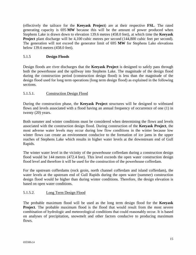
(effectively the tailrace for the Keeyask Project) are at their respective FSL. The rated generating capacity is 695 MW because this will be the amount of power produced when Stephens Lake is drawn down to elevation 139.6 metres (458.0 feet), at which time the Keeyask Project plant discharge will be 4,100 cubic metres per second (144,800 cubic feet per second). The generation will not exceed the generator limit of 695 MW for Stephens Lake elevations below 139.6 metres (458.0 feet). 5.1.5 Design Floods
Design floods are river discharges that the Keeyask Project is designed to safely pass through both the powerhouse and the spillway into Stephens Lake. The magnitude of the design flood during the construction period (construction design flood) is less than the magnitude of the design flood used for long term operations (long term design flood) as explained in the following sections. 5.1.5.1. Construction Design Flood
During the construction phase, the Keeyask Project structures will be designed to withstand flows and levels associated with a flood having an annual frequency of occurrence of one (1) in twenty (20) years. Both summer and winter conditions must be considered when determining the flows and levels associated with the construction design flood. During construction of the Keeyask Project, the most adverse water levels may occur during low flow conditions in the winter because low winter flows can create an environment conducive to the formation of ice jams in the upper reaches of Stephens Lake which results in higher water levels at the downstream end of Gull Rapids. The winter water level in the vicinity of the powerhouse cofferdam during a construction design flood would be 144 metres (472.4 feet). This level exceeds the open water construction design flood level and therefore it will be used for the construction of the powerhouse cofferdam. For the upstream cofferdams (rock groin, north channel cofferdam and island cofferdam), the water levels at the upstream end of Gull Rapids during the open water (summer) construction design flood would be higher than during winter conditions. Therefore, the design elevation is based on open water conditions. 5.1.5.2. Long Term Design Flood
The probable maximum flood will be used as the long term design flood for the Keeyask Project. The probable maximum flood is the flood that would result from the most severe combination of hydrologic and meteorological conditions that could reasonably occur. It is based on analyses of precipitation, snowmelt and other factors conducive to producing maximum flows.
15 693588v14

The Keeyask Project powerhouse and spillway will be able to pass the probable maximum flood flow of 12,700 cubic metres per second (448,500 cubic feet per second) with six of the seven generating units operating at a speed-no-load condition. This probable maximum flood flow is more than double the flood experienced during the summer of 2005, which was the highest recorded daily average flow on the Nelson River at Split Lake since 1908, the year measurements began. Canadian Dam Safety guidelines state that it is not safe to assume that generating units would be producing electricity during a probable maximum flood event and recommend that only a speed-no-load discharge be relied upon. The speed-no-load discharge is the maximum amount of water that can be passed through the powerhouse without risking damage to the generating units when no electricity is being produced. The Keeyask Project speed-no-load flow for all seven units is 1,400 cubic metres per second (49,400 cubic feet per second). During the probable maximum flood event, the remaining 11,300 cubic metres per second (399,100 cubic feet per second) would pass over the spillway. In order for the spillway to pass this much flow, the forebay level would surcharge beyond the FSL of 159.0 metres (521.7 feet), to an elevation of 160.3 metres (525.9 feet). This still would not cause the level of Split Lake to be any higher than would be the case if the Keeyask Project were not built. 5.2 PRINCIPAL STRUCTURES
The principal structures of the Keeyask Project consist of the spillway, powerhouse/service bay complex, central dam, north dam, south dam, transition structures and dykes. The general arrangement of these principal structures is shown in Figure 2. This Project Description is based on the powerhouse housing seven (7) turbines and generators, but it may become desirable to design and build the Keeyask Project utilizing eight (8) turbines and generators, in which event appropriate modifications would be made to the principal structures described in this Project Description. Adding an eighth turbine and generator would not result in material changes to this Project Description, and would not result in any changes to any Fundamental Features. 5.2.1 Concrete Structures
The concrete structures include the intake and powerhouse complex, service bay and control building, spillway and transition structures. These structures will be within the channel of the Nelson River and built on top of bedrock. Foundation grouting will be done under the concrete structures to prevent the seepage of water. Freeboard to accommodate wind setup and wave up rush will vary from 2.5 to 3.5 metres (8.2 to 11.5 feet) for these structures. 5.2.1.1. Intake and Powerhouse Complex
The powerhouse will house seven (7) vertical shaft turbines and generators. Each unit will consist of an intake, scroll case and draft tube, shown in Figure 6. The concrete intake structure will allow water to flow through the scroll case to each of the seven (7) turbine units, where the hydraulic energy will be converted into mechanical energy (rotation of vertical shaft) and then
16 693588v14
converted to electrical energy by generators, located above. The intake for each turbine unit will have three openings, each of which will have a service gate. The intakes will be equipped with trash racks to prevent debris and trash from entering the intakes. Intake and draft tube gates will be provided to enable dewatering of the units for turbine maintenance and repair. Intake bulkhead gates will be provided to facilitate maintenance of the intake gates. 5.2.1.2. Service Bay and Control Building
A service bay (turbine and generator assembly and maintenance area) will be constructed adjacent to the powerhouse. The control building will be attached to the downstream wall of the service bay. 5.2.1.3. Spillway
The function of the spillway is two-fold: it will provide a diversion channel during construction and will provide overflow discharge capacity during operation. The spillway has been designed to protect the Keeyask Project from inflows up to the probable maximum flood (see section 5.1.5.2). The spillway at the Keeyask Project will be a seven-bay overflow structure with individual motorized vertical lift gates located within a channel excavated on the south side of one of the large islands within Gull Rapids, shown in Figure 7. The seven bays will be separated by piers. Stop logs will be used for gate maintenance. There will also be downstream stop logs to allow for dewatering, inspection, and maintenance of the spillway rollway. A bridge for the permanent roadway across the generating station will be supported on the upstream ends of the piers. 5.2.1.4. Transition Structures
Transition structures are concrete gravity structures that would be built to connect the earth structures to the concrete structures. They will be required on the north side of the service bay, the south side of the powerhouse and on both sides of the spillway. Wing walls will be used to contain the earth dams where they connect to the concrete structures. 5.2.2 Earth Structures
As shown in Figure 2, the earth structures consist of dams, which generally will be located within the limits of the river banks, and dykes, which will extend over land upstream along the topographic high points. 5.2.2.1. North, Central and South Dams
As shown in Figure 2, three dams (the north dam, central dam, and south dam), will be constructed across Gull Rapids. The dams will be zoned earth fill embankments consisting of an
17 693588v14

impervious core with granular and crushed rock filters and outer rockfill shells. The elevation of the dams’ crests will range between 162 metres (531.5 feet) and 162.6 metres (533.5 feet). The maximum height of the dams will range between 19.5 and 22 metres (64.0 and 72.2 feet). Typical cross sections for the dams are shown in Figure 8. The earth dams will generally be founded on bedrock. Foundation grouting will be used to prevent seepage under the dams. Seepage through the dams will be intercepted by a system of granular filters and drains. 5.2.2.2. North and South Dykes
A series of earth fill dykes with a total length of about 23 kilometres (14.3 miles) will be located along the north and south sides of the river to contain the reservoir, shown in Figure 2. A roadway will be constructed on top of the dykes and between the sections of dykes for inspection and maintenance. Depending on the topography, foundation conditions, and the presence or absence of permafrost, the design and earth materials used will vary along the dykes. The dykes primarily will be zoned impervious core embankment dykes. Protective shells of crushed rock and riprap will be applied where required. The crest of the dykes will vary between elevations 161.8 metres (530.8 feet) and 163.0 metres (534.8 feet), but may be somewhat higher in areas where the foundations are expected to settle over a period of time. The north dyke and south dyke will have maximum heights of about twenty (20) metres (65.6 feet) and 13 metres (42.7 feet) respectively. Typical cross sections for the dykes are shown in Figure 8. 5.2.2.3. Powerhouse and Spillway Intake Channel and Tailrace Channel
The intake channels and tailrace channels for the powerhouse and spillway, shown in Figure 2, will be excavated through overburden and bedrock in the dry. These channels are required to direct flow into and away from the powerhouse and spillway, respectively. 5.2.2.4. Transmission Tower Spur
The Keeyask Project will utilize a transmission tower spur, shown in Figure 2, to support the foundations for the first row of transmission towers beyond the downstream side of the Keeyask Project. At present, it is assumed that the spur would be located along the southern edge of the tailrace channel. 5.3 SUPPORTING INFRASTRUCTURE
Infrastructure to support construction of the Keeyask Project will include temporary construction camps, contractor work areas, the Project Manager’s engineering and administration office facilities, material storage facilities, cofferdams and service roads, as well
18 693588v14
as infrastructure to provide construction power, the communications system, and water and sewage treatment. The following sections describe the supporting infrastructure, which is illustrated in Figure 3. 5.3.1 Temporary Access Roads
Temporary access roads are required to provide access to areas north and south of the Nelson River as far as 25 kilometres (15.5 miles) upstream of the powerhouse. The access is required to construct the dykes and to clear the reservoir. Access to these areas will be confined to the corridors that will be occupied by the dykes or across the lands that will be inundated once the reservoir is created. A temporary access road may be constructed if the contractors decide to use a potential source of granular material at borrow area E-1, located 12 kilometres (7.5 miles) south of the Keeyask Project construction site, shown in Figure 13. 5.3.2 Permanent Access Roads
Two new permanent, gravel surfaced all weather access roads will be required to construct, operate and maintain the Keeyask Project. The north access road will be within the corridor shown in Figure 1. This road will be the primary access for transporting materials, equipment and workers between Provincial Road 280 and the Keeyask Project site. The south access road linking the Keeyask Project to the Butnau Dam and to Gillam, on the south side of the Nelson River, will be built to support the operation of the Keeyask Project. The south access road will be routed within the corridor shown in Figure 1 and will utilize the existing roadway along the Butnau Dam and Butnau Road. The north and south access roads will be connected by a permanent river crossing over the Keeyask Generating Station’s north dam, powerhouse, central dam, spillway, and south dam. The north and south access roads would be constructed to meet or exceed Manitoba’s requirements. Upon completion of the construction of Keeyask Project, Manitoba has agreed in principle to assume ownership of these roads and re-route Provincial Road 280 across the Keeyask Generating Station. 5.3.3 Construction Camps
At the beginning of construction a temporary road construction camp will be built on the north side of the Nelson River to house staff working on the north access road and the phase one (1) main construction camp. The phase one (1) main construction camp will accommodate approximately 300 workers working on the north access road, the ice boom, the stage one (1) cofferdams and the phase two (2) main construction camp, which will be built to accommodate approximately 1,500 workers. The main construction camp will be located on the north side of the Nelson River. The location of the main camp is shown in Figure 3. The construction camps will be salvaged at the end of the construction.
19 693588v14

5.3.4 Potential Camp Extension
Although not currently planned, it may become necessary to extend the construction camp to develop housing and other facilities for families of individuals employed in the construction of the Keeyask Project. If required, the site for such an extension would be located on the North side of the Nelson River, within relatively close proximity to the construction site shown in Figure 3. 5.3.5 Communications
Communications infrastructure for data, video and voice services will be built in stages to meet communications requirements during construction and ultimately for the operation of the Keeyask Project. 5.3.6 Cofferdams
In preparation for construction of the Keeyask Project principal structures, the river must be carefully managed to create dry, safe working areas. Cofferdams will be constructed and maintained for this purpose. 5.3.6.1. Stage One (1) Cofferdams
Figure 12 illustrates the arrangement of the stage one (1) cofferdams, which will be constructed to allow construction of the powerhouse, spillway, and north and central dams. The stage one (1) cofferdams will be rockfill dams with the upstream zones consisting of a granular filter, impervious glacial till and riprap. When construction of the spillway structure reaches the point at which it can pass water, the stage 1 spillway cofferdam will be removed and the Nelson River diverted through the partially completed spillway. This will be the beginning of stage two (2) diversion. During a one ( 1) in twenty (20) year flood, the water level on Gull Lake would increase by 0.8 m (2.6 ft) due to the stage one (1) cofferdams, but water levels upstream of Birthday Rapids would not be affected. 5.3.6.2. Stage Two (2) Cofferdams
After the Nelson River is diverted through the partially completed spillway, stage 2 cofferdams will be constructed between the south bank of the Nelson River and the spillway south transition in order to construct the south dam, as shown in Figure 12. The stage 2 cofferdams divert all of the flow of the Nelson River through the spillway. The south dam will be constructed on the river bed between the upstream and downstream legs of the stage 2 cofferdams, adjacent to the spillway.
20 693588v14

5.3.7 Ice Boom
An ice boom will be constructed on Gull Lake immediately upstream of Gull Rapids as shown in Figure 3. The ice boom will be required during construction to ensure that an ice cover forms on Gull Lake early in the winter to minimize the formation of a hanging ice dam downstream of Gull Rapids in Stephens Lake, as discussed in section 4.2.1. Without the ice boom, both the stage one (1) and stage two (2) cofferdams would have to be built to higher elevations because the formation of a large ice dam in Stephens Lake would significantly raise water levels near the cofferdams. 5.3.8 Hydro and Contractor Work Areas
Work areas and temporary infrastructure required for construction of the Keeyask Project will be located on the north side of the river, shown in Figure 3. The Hydro work area will contain an engineering office, a storage building, a yard for material storage, a fuel storage facility, vehicle refueling facility, vehicle maintenance facility, field offices, a soils and concrete laboratory, maintenance building, and possibly other facilities. The contractors’ work area would contain storage facilities, facilities to maintain and repair heavy equipment, a fuel storage and vehicle refueling facility, toilet facilities, a concrete batch plant, an aggregate processing area (rock crusher), a carpenters’ shop, a pre-cast concrete yard, a shop to cut and bend reinforcing steel, an office building and other temporary infrastructure required to support construction activities. Magazines for storing explosives, used for blasting rock, will be located away from the work and camp areas. 5.3.9 Construction Power
Electrical power required for the construction of the Keeyask Project will be provided by Hydro by means of two new lines: a new transmission line from the Keeyask Project connecting to an existing transmission line (KN 36) between the Kelsey and Kettle generating stations; and a new pre-built transmission line from the Keeyask Project to the Radisson converter station. Hydro will design, build, operate and maintain all temporary construction power facilities. Certain features of the construction power facilities will be salvaged at the end of construction. 5.3.10 Material Sources and Borrow Areas
The materials required for the Keeyask Project and the supporting infrastructure at site will include impervious fill, granular fill/crushed rock, rock fill, riprap and concrete aggregates. Site investigations have identified a number of natural sources for impervious, rock and granular (sand and gravel) materials, as shown in Figure 13. A number of potential sources for granular material have been identified on the north side of the Nelson River. The only potential source of granular material on the south side of the river is an esker located approximately 12 kilometres (7 miles) south of the site (see section 5.3.1), which will be utilized only if it is economical and
21 693588v14

environmentally acceptable. The exact location and details for processing granular material will be at the discretion of the contractor. 5.3.11 Material Transportation, Rail Siding and Off -Loading Facility
During the construction of the Keeyask Project, freight will be shipped through the City of Thompson, either by rail or by truck, at the discretion of the contractor/supplier. If shipped by rail, the freight will be off-loaded using a rail siding in Thompson and hauled by truck over a distance of 210 kilometres along Provincial Road 280 and the north access road to the Keeyask Project. Upgrades to the rail siding in Thompson will be carried out if required. A small proportion of freight may be handled at the rail siding in Gillam after the south access road is built. As a result of the increased traffic attributable to the construction of the Keeyask Project, upgrades will be required along various sections of Provincial Road 280 between Thompson and the turn-off to the Keeyask Project site to improve safety conditions for the local area users. 5.4 CONSTRUCTION SCHEDULE
The supporting infrastructure, including the north access road, the construction camp and construction power, is required before the Keeyask Generating Station itself can be constructed. Construction of the access road to the site, the first of the supporting infrastructure, will commence when all of the Construction Conditions have been satisfied or waived and the Limited Partnership determines to proceed with construction. The Keeyask Generating Station itself will be constructed in two (2) stages: the first stage will involve the construction of the powerhouse, spillway, central dam and north dam and the second stage will involve diverting the Nelson River through the partially completed spillway to allow the south dam to be constructed. The first turbine will be scheduled for commissioning after six years of construction, followed by an additional two years to complete construction. The construction schedule for the Keeyask Project is shown in Figures 9A and 9B. Figure 11 illustrates the sequence of activities required to construct the Keeyask Project. 5.5 CONSTRUCTION WORKFORCE
The on-site contractor work is estimated to consist of 35,100 person-months of employment with an estimated peak workforce of approximately 1,340 people. The on-site Hydro workforce is estimated to consist of 7,600 person-months of employment with an estimated peak workforce of approximately 140 people, for a total estimated peak on-site workforce of 1,480. Figure 10 illustrates the peak on-site contractor workforce and the peak on-site Hydro workforce by quarter for each year of construction.
22 693588v14
6. PLANT PARAMETERS AND STATION OPERATION
6.1 PLANT PARAMETERS
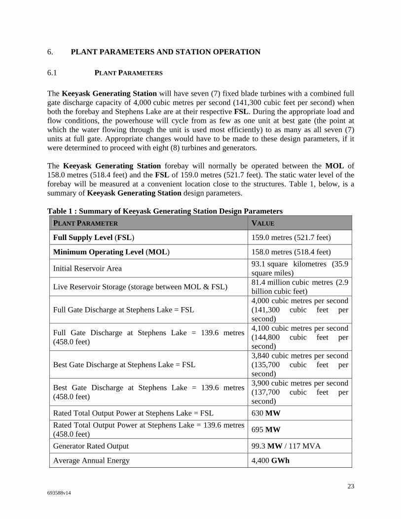
The Keeyask Generating Station will have seven (7) fixed blade turbines with a combined full gate discharge capacity of 4,000 cubic metres per second (141,300 cubic feet per second) when both the forebay and Stephens Lake are at their respective FSL. During the appropriate load and flow conditions, the powerhouse will cycle from as few as one unit at best gate (the point at which the water flowing through the unit is used most efficiently) to as many as all seven (7) units at full gate. Appropriate changes would have to be made to these design parameters, if it were determined to proceed with eight (8) turbines and generators. The Keeyask Generating Station forebay will normally be operated between the MOL of 158.0 metres (518.4 feet) and the FSL of 159.0 metres (521.7 feet). The static water level of the forebay will be measured at a convenient location close to the structures. Table 1, below, is a summary of Keeyask Generating Station design parameters. Table 1 : Summary of Keeyask Generating Station Design Parameters
PLANT PARAMETER VALUE
Full Supply Level (FSL) 159.0 metres (521.7 feet)
Minimum Operating Level (MOL) 158.0 metres (518.4 feet)
Initial Reservoir Area 93.1 square kilometres (35.9 square miles)
Live Reservoir Storage (storage between MOL & FSL) 81.4 million cubic metres (2.9 billion cubic feet)
Full Gate Discharge at Stephens Lake = FSL 4,000 cubic metres per second (141,300 cubic feet per second)
Full Gate Discharge at Stephens Lake = 139.6 metres (458.0 feet)
4,100 cubic metres per second (144,800 cubic feet per second)
Best Gate Discharge at Stephens Lake = FSL 3,840 cubic metres per second (135,700 cubic feet per second)
Best Gate Discharge at Stephens Lake = 139.6 metres (458.0 feet)
3,900 cubic metres per second (137,700 cubic feet per second)
Rated Total Output Power at Stephens Lake = FSL 630 MW Rated Total Output Power at Stephens Lake = 139.6 metres (458.0 feet) 695 MW
Generator Rated Output 99.3 MW / 117 MVA
Average Annual Energy 4,400 GWh
23 693588v14

PLANT PARAMETER VALUE
Annual Dependable Energy 2,900 GWh 6.2 MODES OF OPERATION
The Keeyask Generating Station will operate as a modified peaking plant, meaning that it will operate either in a peaking mode of operation or a base loaded mode of operation. The extent of peaking or base loaded mode of operation will be determined by the flows in the Nelson River and the requirements of the Integrated Power System. There also will be occasions when the Keeyask Project will be required to operate in a special or emergency mode of operation, as described in this section. 6.2.1 Peaking Mode of Operation
When the Keeyask Generating Station operates in a peaking mode, water stored in the reservoir will be used to augment inflows so that maximum power can be generated during the day to coincide with peak power demand. At night, when power demand is lower, flow through the station will be reduced to store water in the reservoir for use during the next day, resulting in an overnight increase in the forebay level. This peaking mode of operation can be used when inflows are less than the full gate discharge capacity of 4,000 cubic metres per second (141,300 cubic feet per second). Based on flow records since the LWR and CRD have been in operation, the Keeyask Generating Station could operate in a peaking mode up to about 80% of the time. Based on the same flow record, the spillway could be used about five (5% ) per cent of the time. The Keeyask Generating Station forebay will fluctuate up to 1.0 metre (3.3 feet), between the FSL and the MOL, during a peaking mode of operation. The largest water level fluctuations will occur when Nelson River flows are low to above average. The water level fluctuations will be less at higher flows. Peaking will not be possible when the inflow is greater than or equal to the full gate discharge capacity. When the Nelson River inflows are in the range that permits operation in the peaking mode, the Keeyask Generating Station forebay typically will be at its FSL at the beginning of the week (Monday morning). The inflows to the forebay will be supplemented by water drawn out of storage during the day to allow the station to generate maximum power during the 16 on-peak hours (6 am to 10 pm). Typically, the forebay then will be partly re-filled at night by reducing power generation during the 8 off-peak hours (10 pm to 6 am). The Keeyask Generating Station will be operated such that the combination of on-peak generation and off-peak generation will utilize the reservoir storage over the five week days, so the forebay will reach its MOL at the end of the week (Friday evening). During the weekend, on-peak generation will be reduced such that the forebay will fill up to its FSL by Monday morning. Although the foregoing describes what typically will happen, there will be no requirement to fill the forebay to its FSL by Sunday or Monday morning, or at any other particular time.
24 693588v14
During low inflow conditions the Keeyask Generating Station will be unable to operate at full gate plant discharge for extended periods of time because there will be insufficient reservoir storage to do so. It will be uneconomic to operate the Keeyask Generating Station at its MOL. At low inflows, it becomes increasingly economic to maintain the Keeyask Generating Station forebay at or near its FSL, allowing the Kettle, Long Spruce, and Limestone generating stations to provide the peak capacity on the Integrated Power System. During low inflow, high load and/or high export and import price conditions, the Keeyask Generating Station may peak for periods less than five days, rather than over the entire week. The forebay could be drawn down through its full storage range in one day or more and may not be filled to its FSL. 6.2.2 Base Loaded Mode of Operation
When the Keeyask Generating Station operates in a base loaded mode, the forebay will remain relatively stable at or near the FSL and the outflow from the station will be approximately equal to the inflow. Based on inflow records since the LWR and CRD have been in operation, the Keeyask Generating Station could be expected to operate in a base loaded mode of operation 20% of the time or more. Base loaded operation will occur whenever inflows are greater than or equal to the plant discharge capacity of 4,000 cubic metres per second (141,300 cubic feet per second). Based on inflow records since the LWR and CRD have been in operation, this would occur about five (5% ) per cent of the time. It also may occur when the Integrated Power System is short of system energy, which, based on historic inflow records, would occur approximately fifteen (15%) per cent of the time and typically would correspond with low inflow conditions. While the Keeyask Generating Station could be operated in a base loaded mode during any inflow condition, this would only be done when the forebay is above its MOL, except in emergency conditions. 6.2.3 Special Operating Conditions
Special conditions may occur in which the Keeyask Generating Station may not be operated in either a peaking or base loaded mode of operation. Special conditions include load rejection (units tripping off due to mechanical, transmission or other problems), flood management, or meteorological events. If a load rejection occurs when the forebay is at the FSL, the forebay level will rise until either the spillway gates are raised to pass the surplus inflow or the units are brought back on line and the forebay brought back to the FSL. The static water level of the forebay may rise above the FSL during flood events with a probability of occurrence of 0.0001 (a frequency of less than once in 10,000 years), assuming the Keeyask Generating Station is operating at speed-no-load conditions (see section 5.1.5.2). In addition, meteorological events (such as a heavy rainstorm) and non-Keeyask Project related hydraulic effects (such as a sudden change in ice conditions) from time to time may cause the
25 693588v14
water level in the forebay of the Keeyask Generating Station to exceed the FSL or be drawn down below the MOL. When the water level in the forebay during these special operating conditions exceeds the FSL or is drawn down below the MOL, the Keeyask Generating Station will be operated as described in section 6.2.5. 6.2.4 Emergency Operating Conditions
Emergency conditions may require the Keeyask Generating Station to operate in a mode of operation that is different than all other modes of operation. Emergency conditions include a risk of imminent failure of one of the dams or dykes, or when the flow passing through the Keeyask Generating Station needs to be halted temporarily, for example, due to a downstream accident. During emergencies there may be a rapid forebay drawdown (such as during an imminent failure scenario) or a rapid forebay surcharging (such as when outflow through the station is halted in the event of a downstream accident). In circumstances such as these, the static water level of the forebay could rise above its FSL or fall below its MOL. At the same time, the flow increases or decreases necessitated by the emergency, including flow reductions to zero if necessary, would result in greater changes in the tailwater levels than would be experienced during normal operating conditions. When the water level in the forebay during these emergency operating conditions exceeds the FSL or is drawn down below the MOL, the Keeyask Generating Station will be operated as described in section 6.2.5. 6.2.5 Special or Emergency Mode of Operation
In most cases under special or emergency operating conditions, the variations from the normal operating range between the FSL and the MOL will be 0.5 metres (1.6 feet) or less. At any time when the forebay level is above 159.5 metres (523.3 feet), the Keeyask Generating Station will be operated to increase the combined discharges through the powerhouse and spillway to the maximum extent that safety or licence considerations allow, without regard for economic considerations. At any time when the forebay level is below 157.5 metres (516.7 feet), the Keeyask Generating Station will be operated to decrease the combined discharges through the powerhouse and spillway to the maximum extent safety or licence considerations allow, without regard for economic considerations. 6.3 MINIMUM DISCHARGE
The Keeyask Generating Station discharge during the off-peak periods (weekday nights and weekends) will not be less than one unit operating at best gate discharge, except during extremely low inflow conditions and/or as specified in license conditions.
26 693588v14

6.4 OPERATIONAL WORKFORCE
Hydro has estimated that a total of forty-six (46) staff will be required to operate and support the Keeyask Project. A total of thirty-seven (37) staff will work at the station and nine (9) staff will work in Gillam. Table 2 lists the types and number of staff estimated to be required. Table 2: Estimated Keeyask Project On-Site and Off-Site Staff Requirements During Operating Phase
WORKFORCE TYPE NUMBER OF STAFF
Staff Located at Keeyask Project:Power Supply Worker – Electrical 8 Power Supply Worker – Mechanical 8 Plant Manager 1 Supervisor – Electrical 1 Supervisor – Mechanical 1 Planner 1 Engineering Technician 1 Administration Representative 1 Store Keeper 1 Utility Workers 4 Welder 1 Apprentice – Electrical 4 Apprentice – Mechanical 4 Janitor 1
Sub-Total 37 Staff Located in Gillam:
Engineering Technician – Mechanical 1 Engineering Technician – Electrical 1 Engineering Technician – Civil 1 IT/Communications/Testing 1 Gillam Services – Trades 3 Debris Management / Safe Winter Trails 2
Sub-Total 9 Total Staff at Keeyask Project and at Gillam 46
6.5 KEEYASK GENERATING STATION HYDRAULIC ZONE OF INFLUENCE
The operation of the Keeyask Generating Station will affect water levels both upstream and downstream and the effects would be different during open water and winter conditions. Figures 4 and 14 illustrate the spatial extent of the hydraulic zone of influence of the Keeyask Project.
27 693588v14
6.5.1 Open Water Conditions - Upstream
Engineering calculations were used to estimate water surface profiles for the Split Lake to Gull Rapids reach of the Nelson River during a range of flow conditions, assuming the Keeyask Generating Station is in operation, as shown in Figure 4. The water surface profiles are the best estimates that can be made with present data. They show that during open water conditions, the backwater effects created by the Keeyask Project will drown out Birthday Rapids and cause some increases in water levels upstream of Birthday Rapids, but will not affect the water level on Split Lake during open water conditions. During open water conditions, the upstream boundary of the hydraulic zone of influence of the Keeyask Project will be located between the outlet of Clark Lake and Birthday Rapids, its specific location at any particular moment being dependent on the forebay level and inflow conditions. When the Keeyask Generating Station is operating in a peaking mode, the water level in the section of the reservoir about 19 kilometres (12 miles) upstream of the powerhouse could fluctuate as much as 1 metre (3.3 feet) within a one (1) day period. The magnitude of the water level variation would diminish further upstream to the upstream boundary of the hydraulic zone of influence. If a flood as significant as the probable maximum flood (12,700 cubic metres per second or 448,500 cubic feet per second) were to occur during open water conditions, there would be no effect on the level of Split Lake caused by the Keeyask Project. If, conservatively, the powerhouse were discharging speed-no-load flow for all seven units, the forebay would surcharge to 160.3 metres (525.9 feet), as discussed in section 5.1.5.2. If the powerhouse were able to maintain normal operations during the probable maximum flood, no surcharging of the forebay would occur. 6.5.2 Open Water Conditions - Downstream
The water level at the Keeyask Generating Station tailrace (immediately downstream of the powerhouse) will be mainly a function of the level of Stephens Lake. There will be a slight gradient over the approximately 3 kilometre (1.9 mile) reach between the powerhouse tailrace and Stephens Lake; the amount of gradient will depend on the magnitude of the Keeyask Generating Station discharge and the level of Stephens Lake. The maximum drop in elevation along this river reach would be approximately 0.1 metres (4 inches). Due to the varying outflow from the Keeyask Generating Station, the water levels between the station and Stephens Lake will fluctuate a small amount within any given day and will be limited to the tailrace area. The magnitude of the water level variation will depend on the plant discharge and the amount of cycling at the Keeyask Generating Station. This small water level variation due to changing outflow from the Keeyask Generating Station will be superimposed on a larger range of water level fluctuations that occurs on Stephens Lake as a result of the operation of the Kettle generating station. Since the Kettle generating station began operation, the water level on Stephens Lake (measured at the Kettle generating station) has varied between 139.1 metres (449.8 feet) and 141.3 metres (463.6 feet). For 90 percent of the time, the Stephens Lake water level has varied between 139.3 metres (454.0 feet) and 141.1 metres (463.0 feet). During
28 693588v14

extremely high inflow conditions, the maximum water level on Stephens Lake could reach 141.7 metres (464.9 feet). The range of elevations on Stephens Lake will remain unchanged after the Keeyask Generating Station is operational. 6.5.3 Winter Conditions
Many climatic and hydraulic factors affect the formation of ice on the reach of the Nelson River between Split Lake and Stephens Lake. During the winter months the water levels along this river reach are affected by ice processes. Ice conditions can vary considerably from year to year, depending on factors such as weather, ice bridging locations and river flows. The following sections describe how the ice processes will change once the Keeyask Generating Station becomes operational. 6.5.3.1. Winter Conditions - Upstream
The Keeyask Generating Station forebay will resemble a lake environment, similar to the conditions found on Stephens Lake. At the onset of winter, the Keeyask Generating Station forebay will develop a relatively smooth thermal ice cover, which will extend approximately 25 kilometres (16 miles) upstream of the station. Frazil ice pans and sheets will then collect at the upstream edge of this thermal ice cover, which will allow the ice covered surface to advance through Birthday Rapids more quickly and earlier in the winter compared to current conditions. The conditions and events that would cause increased water levels on Split Lake also occur at present (see section 4.2.1). Currently, anchor ice restricts river flows and causes upstream water levels to rise on both Clark Lake and Split Lake every winter. When compared to the level on Split Lake without the Keeyask Generating Station, it is estimated that with the Keeyask Generating Station the winter level of Split Lake will be higher about 1 year in 20. However, even with the increased water level on Split Lake due to the Keeyask Generating Station, the level on Split Lake will remain within the range of winter levels that has been experienced since CRD and LWR have been in operation. At present, anchor ice formation at the outlet of Clark Lake typically leads to water level increases on Split Lake of up to 0.6 metres (2.0 feet) every winter. It is estimated that there will be an additional increase to the water level on Split Lake (estimated to be less than 0.2 metres (8 inches) during the winter due to the development and operation of the Keeyask Generating Station. This backwater effect will occur only during low flow conditions when Split Lake outflows are in the range of 1,500 to 2,500 cubic metres per second (53,000 to 88,300 cubic feet per second), which occurs about one (1) year in twenty (20) based on historic flows post CRD and LWR. This potential effect would be due to the ice front progressing faster to Birthday Rapids and then through Birthday Rapids with the Keeyask Generating Station in place. The magnitude of increased water levels on Split Lake during such periods of low flows will vary from occurrence to occurrence and will depend on air temperatures, river flows and other conditions. This backwater effect would be dampened if anchor ice which has formed near the outlet of Clark Lake continues to form once the Keeyask Generating Station is in operation.
29 693588v14

An expanded water level monitoring program between Split Lake and Stephens Lake has been in place for several years to gather information to develop an improved understanding of the ice formation processes and to provide baseline data to estimate the effects of the Keeyask Generating Station. 6.5.3.2. Winter Conditions - Downstream
At the onset of winter, the reach of river between the Keeyask Generating Station and Stephens Lake will develop a relatively smooth thermal ice cover. An open water area immediately downstream of the powerhouse will exist throughout the winter, due in part to the continued turbulence in this area. The ice cover downstream of the Keeyask Generating Station and into Stephens Lake throughout the winter will resemble an ice cover typically found on lakes. The Keeyask Generating Station will prevent the formation of the ice dam that typically develops at the base of Gull Rapids and into Stephens Lake. 6.6 FLOODED AREA
As a result of the Keeyask Generating Station the water levels on Gull Lake will rise approximately 6 metres (19.7 feet), which will result in approximately 45 square kilometres (17.4 square miles) of land being flooded immediately following impoundment, as shown in Figure 14. Erosion of peatlands and mineral shorelines in the years following initial impoundment will cause the shoreline to recede at various locations and cause the area of flooded land to increase.
30 693588v14
7. ENHANCEMENT MEASURES TO REDUCE ADVERSE EFFECTS
The Keeyask Project has been designed by Hydro in cooperation with the Keeyask Cree Nations to avoid, reduce, or mitigate adverse effects. 7.1 PROJECT DESIGN & OPERATION
Hydro has given priority to the avoidance or reduction of adverse effects in the design of the Keeyask Project and the operating parameters of the Keeyask Generating Station. The forebay FSL of 159.0 metres (521.7 feet) was agreed to so that the operation of the Keeyask Generating Station will not affect the water level on Split Lake during open water conditions. The operating range of 1.0 metre (3.3 feet) between the FSL and the MOL will avoid or reduce many potential adverse effects of the Keeyask Project. 7.2 MEASURES TO ALLEVIATE ADVERSE EFFECTS
In addition to design and operation considerations, Hydro and the Keeyask Cree Nations have agreed upon a number of programs and plans to reduce the potential impacts of the Keeyask Project. Some of the plans and programs have seldom or never been used in northern Manitoba and it is expected that ongoing monitoring will be required to determine their success. As a result of the monitoring, and following consultation with the Keeyask Cree Nations, some aspects of the plans and programs may be modified, expanded, reduced, or eliminated, depending on their degree of success. 7.2.1 Reservoir Clearing & Waterways Management
The Reservoir Clearing Plan, attached as Schedule 11-1 to the JKDA, sets out standards and guidelines, as well as a timeline, for the clearing of the areas to be flooded. Woody debris that is mobilized during the flooding of the reservoir and that may present a hazard to navigation or impact Hydro’s operations will be removed during and immediately following reservoir impoundment, as set out in the Waterways Management Program, attached as Schedule 11-2 to the JKDA. 7.2.2 Reservoir Depth Charts and Travel Routes
Depth charts for the Keeyask Generating Station reservoir will be developed to illustrate the depth of water throughout the reservoir as an aid for boat travel. Using the water level readings from water level gauges, the charts may be used to determine the depth of water throughout the reservoir at the instant in time of the water level measurement. As an example, a preliminary reservoir depth chart is shown in Figure 16, which illustrates the depth of water during low flow conditions and when the forebay is at the MOL level of 158 metres (518.4 feet).
31 693588v14

The depth chart will also illustrate safe travel routes that should be used during all water level conditions. The chart will indicate the approximate depth of water along each route, also shown in Figure 16. 7.2.3 Navigation and Hazard Marking
Navigation buoys will be installed and maintained along primary travel routes and along charted routes to shore access points at locations where there is a serious risk of striking a rock or reef depending on water level. Private Buoy Regulations under The Canada Shipping Act will be adhered to with respect to placement, display, size and maintenance of buoys. The location of the navigation and hazard buoys would be indicated on the reservoir depth charts, as shown in Figure 16. 7.2.4 Reservoir Water Level Information
A series of manual water level gauges (staff gauges) will be located near selected access points to show the water level at that location. The water level gauges will provide information required to interpret the reservoir depth charts and determine the depth of water along travel routes. Water level forecasts for Split Lake and Stephens Lake will continue to be provided. The preliminary locations of the water level gauges are shown on Figure 16. 7.2.5 Safe Landing Sites
Recognizing that the reservoir will be used for resource harvesting, boat travel and a variety of other pursuits, a number of potential landing sites have been identified along the shoreline. These landing sites also would be used for emergency purposes. 7.2.6 Ice Monitoring & Safe Trails Program
The forebay and tailrace areas generally will have safer ice conditions following the construction of the Keeyask Project than existed prior to construction. There will be locations, however, where travel on the ice will be dangerous and where ice conditions will be unknown or uncertain, especially during the first few winters. Safe trails over the ice will be marked each year. Ice development will be monitored for a number of years to help identify and map safe travel areas and unsafe travel areas. Monitoring will continue until ice travel maps are considered reliable. 7.2.7 Historic Resources Protection/Preservation
The new shoreline following construction of the Keeyask Project will be surveyed periodically to identify culturally significant sites so that they can be protected or preserved. This program will be implemented with the Waterways Management Program and requires that boat patrol staff be trained to identify historic resources or that trained staff are present on selected boat patrols.
32 693588v14
7.3 DISTURBED SITE RECLAMATION
Borrow areas, quarry sites, work areas, temporary access roads, settling ponds and on-land spoil deposition sites are all areas that would be disturbed as a result of the construction of the Keeyask Project. When reclaiming these disturbed sites, measures based on best management practices, guidelines, and regulations will be used to stabilize soils and prevent erosion, following, wherever practical, principles that give regard to the Keeyask Cree Nations’ concern for respecting the land. Specific plans or locations for reclamation activities cannot be identified prior to the completion of the EIS and the Environmental Protection Plans. 7.3.1 Principles Regarding Respect for the Land
Principles that guide the Keeyask Cree Nation’s objectives regarding respect for the land include the following:
(a) adopting measures that increase, to the extent ecologically reasonable, the abundance of species and/ or growing conditions for species that have special social or economic importance for the Keeyask Cree Nations;
(b) employing strategies that “go with” rather than “go against” nature, as they have a much higher probability of success;
(c) planting species and promoting site conditions that are widespread in the sub-region in which the Keeyask Project is located, rather than planting species and promoting site conditions that may be popular in more southern areas; and
(d) being respectful of the Keeyask Cree Nations’ traditional relationships with the land.
7.3.2 Measures
Measures that may be considered to comply with the above principles include:
(a) altering existing soil, topography and hydrology as little as possible;
(b) anticipating ecosystem dynamics and fitting in with how the habitat would develop over time; and
(c) attempting to create conditions that promote selected species (for example, narrow-leaved Labrador tea).
33 693588v14