schneider ns mccb
TRANSCRIPT
Issued October 2009 12481
DATA SHEET
NS MCCB Based on Schneider LVPED208012EN Catalogue
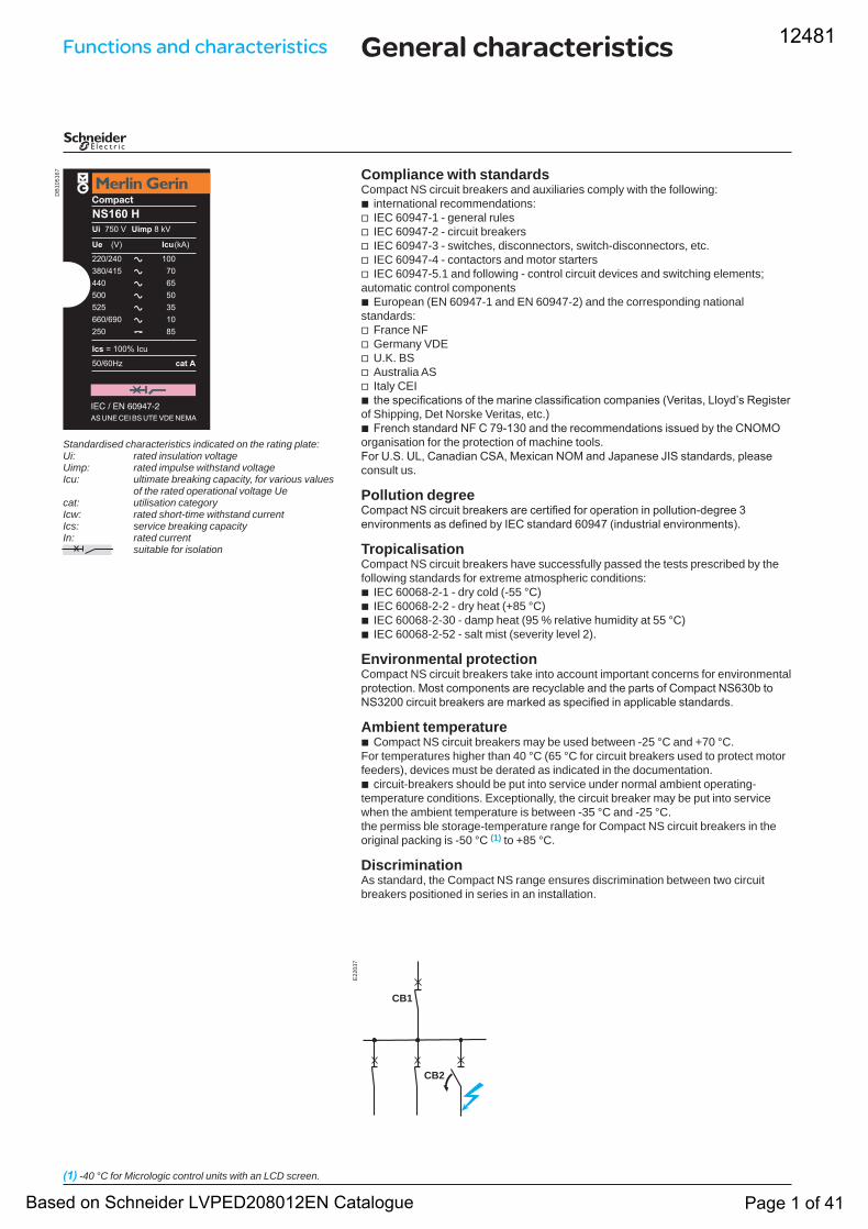
Compliance with standardsCompact NS circuit breakers and auxiliaries comply with the following:
international recommendations:IEC 60947-1 - general rulesIEC 60947-2 - circuit breakersIEC 60947-3 - switches, disconnectors, switch-disconnectors, etc.IEC 60947-4 - contactors and motor startersIEC 60947-5.1 and following - control circuit devices and switching elements;
automatic control componentsEuropean (EN 60947-1 and EN 60947-2) and the corresponding national
standards:France NFGermany VDEU.K. BSAustralia ASItaly CEIthe specifications of the marine classification companies (Veritas, Lloyd’s Register
of Shipping, Det Norske Veritas, etc.)French standard NF C 79-130 and the recommendations issued by the CNOMO
organisation for the protection of machine tools.For U.S. UL, Canadian CSA, Mexican NOM and Japanese JIS standards, please consult us.
Pollution degreeCompact NS circuit breakers are certified for operation in pollution-degree 3 environments as defined by IEC standard 60947 (industrial environments).
TropicalisationCompact NS circuit breakers have successfully passed the tests prescribed by the following standards for extreme atmospheric conditions:
IEC 60068-2-1 - dry cold (-55 °C)IEC 60068-2-2 - dry heat (+85 °C)IEC 60068-2-30 - damp heat (95 % relative humidity at 55 °C)IEC 60068-2-52 - salt mist (severity level 2).
Environmental protectionCompact NS circuit breakers take into account important concerns for environmental protection. Most components are recyclable and the parts of Compact NS630b to NS3200 circuit breakers are marked as specified in applicable standards.
Ambient temperatureCompact NS circuit breakers may be used between -25 °C and +70 °C.
For temperatures higher than 40 °C (65 °C for circuit breakers used to protect motor feeders), devices must be derated as indicated in the documentation.
circuit-breakers should be put into service under normal ambient operating-temperature conditions. Exceptionally, the circuit breaker may be put into service when the ambient temperature is between -35 °C and -25 °C.the permiss ble storage-temperature range for Compact NS circuit breakers in the original packing is -50 °C (1) to +85 °C.
DiscriminationAs standard, the Compact NS range ensures discrimination between two circuit breakers positioned in series in an installation.
bvvvvv
b
vvvvvb
b
bbbb
b
b
General characteristics
(1) -40 °C for Micrologic control units with an LCD screen.
Standardised characteristics indicated on the rating plate:Ui: rated insulation voltageUimp: rated impulse withstand voltageIcu: ultimate breaking capacity, for various values
of the rated operational voltage Uecat: utilisation categoryIcw: rated short-time withstand currentIcs: service breaking capacityIn: rated current
suitable for isolation
DB
1051
67
E22
037
CB2
CB1
Functions and characteristics 12481
Based on Schneider LVPED208012EN Catalogue Page 1 of 41
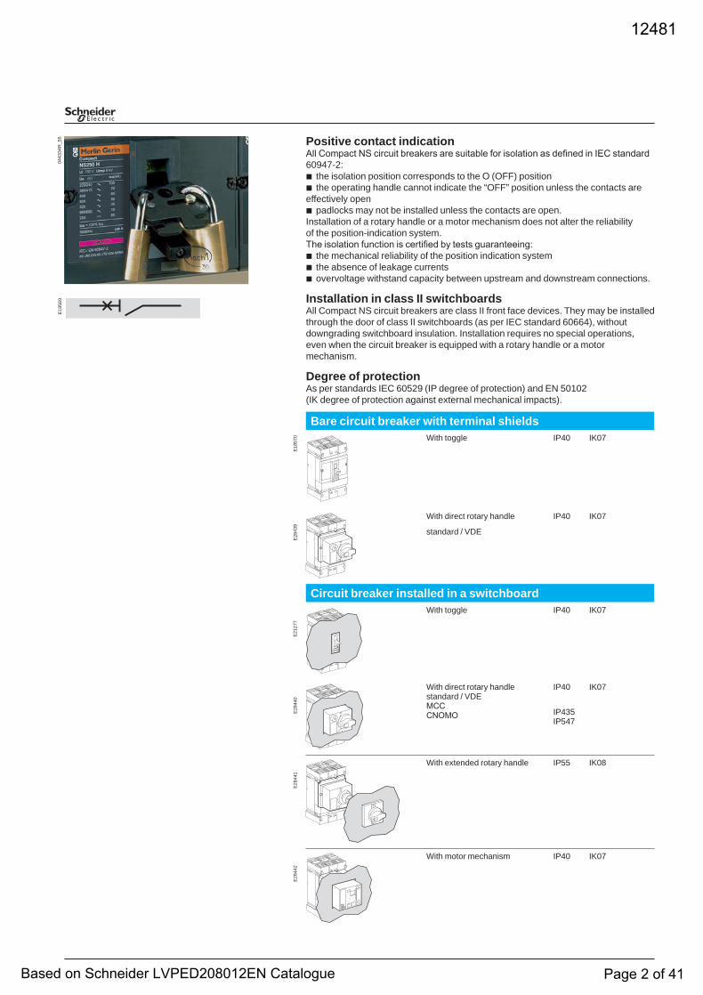
Positive contact indicationAll Compact NS circuit breakers are suitable for isolation as defined in IEC standard 60947-2:
the isolation position corresponds to the O (OFF) positionthe operating handle cannot indicate the “OFF” position unless the contacts are
effectively openpadlocks may not be installed unless the contacts are open.
Installation of a rotary handle or a motor mechanism does not alter the reliability of the position-indication system.The isolation function is certified by tests guaranteeing:
the mechanical reliability of the position indication systemthe absence of leakage currentsovervoltage withstand capacity between upstream and downstream connections.
Installation in class II switchboardsAll Compact NS circuit breakers are class II front face devices. They may be installed through the door of class II switchboards (as per IEC standard 60664), without downgrading switchboard insulation. Installation requires no special operations, even when the circuit breaker is equipped with a rotary handle or a motor mechanism.
Degree of protectionAs per standards IEC 60529 (IP degree of protection) and EN 50102(IK degree of protection against external mechanical impacts).
bb
b
bbb
Bare circuit breaker with terminal shieldsWith toggle IP40 IK07
ON
OO F
With direct rotary handle IP40 IK07
standard / VDE
Circuit breaker installed in a switchboardWith toggle IP40 IK07
ON
F
With direct rotary handle standard / VDE MCCCNOMO
IP40 IK07
IP435IP547
NO
F
NO
FO
With extended rotary handle IP55 IK08
Ih
OO
1
m n u
With motor mechanism IP40 IK07
E28
442
E28
441
E28
440
E21
277
E28
439
E18
570
0443
34R
_55
E18
569
12481
Based on Schneider LVPED208012EN Catalogue Page 2 of 41
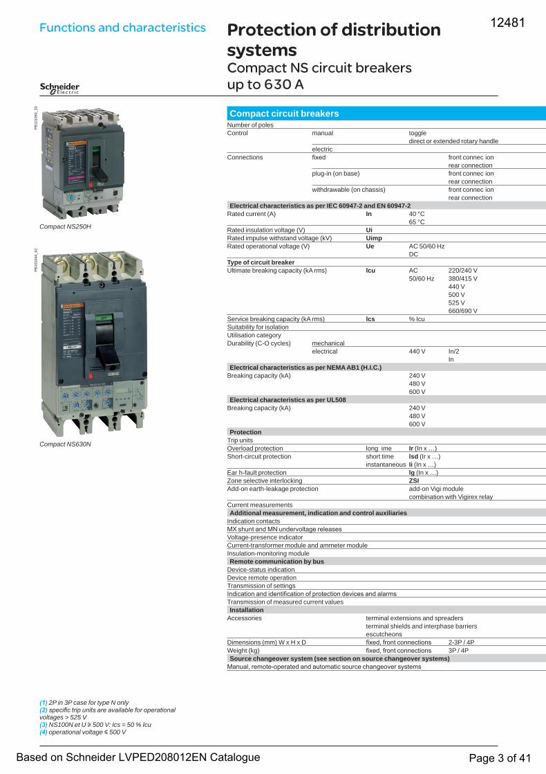
Protection of distribution systemsCompact NS circuit breakers up to 630 A
PB
1010
50_3
3
Compact NS250H
PB
1010
44_4
2
Compact NS630N
(1) 2P in 3P case for type N only(2) specific trip units are available for operational voltages > 525 V(3) NS100N et U u 500 V: Ics = 50 % Icu(4) operational voltage y 500 V
Compact circuit breakersNumber of poles 2 2 2 Control manual toggle
direct or extended rotary handleelectric
Connections fixed front connec ionrear connection
plug-in (on base) front connec ionrear connection
withdrawable (on chassis) front connec ionrear connection
Electrical characteristics as per IEC 60947-2 and EN 60947-2Rated current (A) In 40 °C 12 1 1 2
65 °C 1 1 22 2Rated insulation voltage (V) UiRated impulse withstand voltage (kV) UimpRated operational voltage (V) Ue AC 50/60 Hz
DCType of circuit breakerUltimate breaking capacity (kA rms) lcu AC 220/240 V 2 1 1 1 1 1 1 1 1 1 1
50/60 Hz 380/415 V 1 1 1 1 1 1 1440 V 1 1 1 1 2 1 2 1500 V 2 1 1525 V 22 1 22 22 22 1 22660/690 V 1 1 1 1 2 1 1 2 1 2 1 2
Service breaking capacity (kA rms) lcs % Icu 1 1 1 1 1 Suitability for isolationUtilisation categoryDurability (C-O cycles) mechanical 1 2 1 1
electrical 440 V In/2 2 12In 2 1
Electrical characteristics as per NEMA AB1 (H.I.C.)Breaking capacity (kA) 240 V 1 2 1 2 1 2 1 2 1 2
480 V 1 1 1 2 1 2 1600 V 2 2 2 2 2 2 2
Electrical characteristics as per UL508Breaking capacity (kA) 240 V
480 V 2600 V 1 1 1 1 1 1 1 1 1
ProtectionTrip units 22 2Overload protection long ime Ir (In x …) 12 12Short-circuit protection short time lsd (Ir x …)
instantaneous Ii (In x …)Ear h-fault protection lg (In x …)Zone selective interlocking ZSIAdd-on earth-leakage protection add-on Vigi module
combination with Vigirex relayCurrent measurementsAdditional measurement, indication and control auxiliaries
Indication contactsMX shunt and MN undervoltage releasesVoltage-presence indicatorCurrent-transformer module and ammeter moduleInsulation-monitoring moduleRemote communication by bus
Device-status indicationDevice remote operationTransmission of settingsIndication and identification of protection devices and alarmsTransmission of measured current valuesInstallation
Accessories terminal extensions and spreadersterminal shields and interphase barriersescutcheons
Dimensions (mm) W x H x D fixed, front connections 2-3P / 4P 1 1 1 1 1 1 1 2 11 1 2 11Weight (kg) fixed, front connections 3P / 4P 2 2 2 2 2 2 1Source changeover system (see section on source changeover systems)
Manual, remote-operated and automatic source changeover systems
Functions and characteristics 12481
Based on Schneider LVPED208012EN Catalogue Page 3 of 41
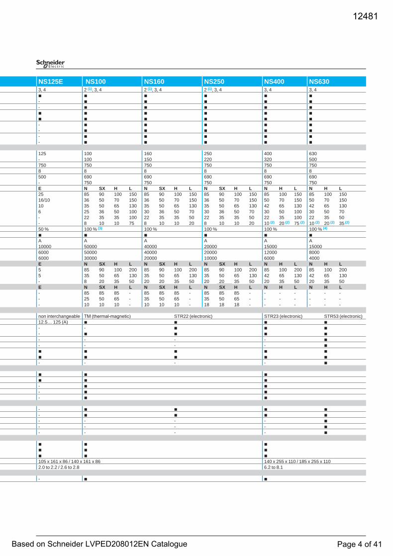
NS125E NS100 NS160 NS250 NS400 NS630 3, 4 2 (1), 3, 4 2 (1), 3, 4 2 (1), 3, 4 3, 4 3, 4
b b b b b b - b b b b b
- b b b b bb b b b b bb b b b b b
- b b b b b- b b b b b
- b b b b b- b b b b b
125 100 160 250 400 630
- 100 150 220 320 500 750 750 750 750 750 750 8 8 8 8 8 8 500 690 690 690 690 690
- 750 750 750 750 750 E N SX H L N SX H L N SX H L N H L N H L
22 2 25 85 90 100 150 85 90 100 150 85 90 100 150 85 100 150 85 100 1501 16/10 36 50 70 150 36 50 70 150 36 50 70 150 50 70 150 50 70 150
10 35 50 65 130 35 50 65 130 35 50 65 130 42 65 130 42 65 1306 25 36 50 100 30 36 50 70 30 36 50 70 30 50 100 30 50 70
2 - 22 35 35 100 22 35 35 50 22 35 35 50 22 35 100 22 35 50- 8 10 10 75 8 10 10 20 8 10 10 20 10 (2) 20 (2) 75 (2) 10 (2) 20 (2) 35 (2)
50 % 100 % (3) 100 % 100 % 100 % 100 % (4)
b b b b b bA A A A A A
10000 50000 40000 20000 15000 15000 2 6000 50000 40000 20000 12000 8000
6000 30000 20000 10000 6000 4000 E N SX H L N SX H L N SX H L N H L N H L
2 5 85 90 100 200 85 90 100 200 85 90 100 200 85 100 200 85 100 2005 35 50 65 130 35 50 65 130 35 50 65 130 42 65 130 42 65 130- 8 20 35 50 20 20 35 50 20 20 35 50 20 35 50 20 35 50
E N SX H L N SX H L N SX H L N H L N H L 2 - 85 85 85 - 85 85 85 - 85 85 85 - - - - - - -
- 25 50 65 - 35 50 65 - 35 50 65 - - - - - - -- 10 10 10 - 10 10 10 - 18 18 18 - - - - - - -
non interchangeable TM (thermal-magnetic) STR22 (electronic) STR23 (electronic) STR53 (electronic) 12.5… 125 (A) b b b b
- - b b b - b b b b
- - - - b - - - - b
b b b b b b b b b b
- - - - b
b b b b b b
- b b - b b
- b b
- b b b b - b b b b
- - - - b - - - - b
- - - - b
b b b b b b
b b b 2 105 x 161 x 86 / 140 x 161 x 86 140 x 255 x 110 / 185 x 255 x 110
2.0 to 2.2 / 2.6 to 2.8 6.2 to 8.1
- b b
12481
Based on Schneider LVPED208012EN Catalogue Page 4 of 41
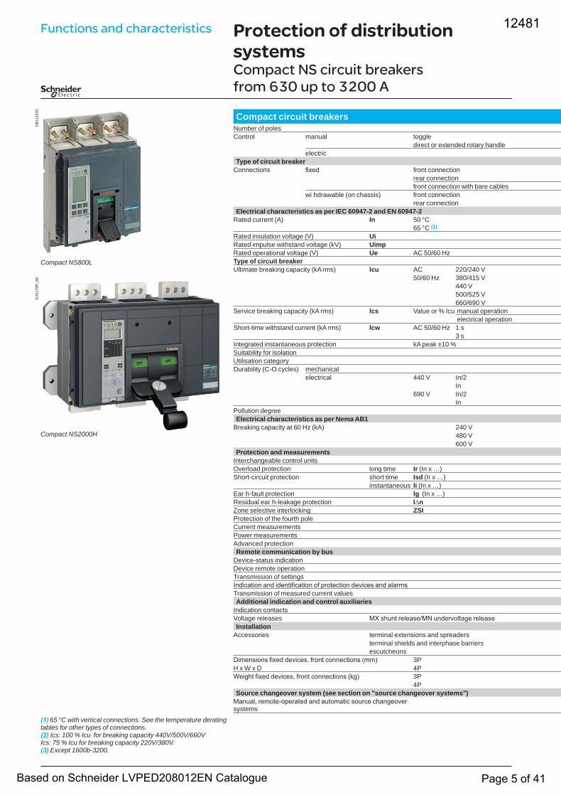
Protection of distribution systemsCompact NS circuit breakers from 630 up to 3200 A
DB
1125
30
Compact NS800L
E45
178R
_68
Compact NS2000H
(1) 65 °C with vertical connections. See the temperature derating tables for other types of connections.(2) Ics: 100 % Icu for breaking capacity 440V/500V/660VIcs: 75 % Icu for breaking capacity 220V/380V.(3) Except 1600b-3200.
Compact circuit breakersNumber of poles Control manual toggle
direct or extended rotary handleelectric
Type of circuit breakerConnections fixed front connection
rear connectionfront connection with bare cables
wi hdrawable (on chassis) front connectionrear connection
Electrical characteristics as per IEC 60947-2 and EN 60947-2Rated current (A) In 50 °C 1 12 1 1 2 2 2
65 °C (1) 1 12 1 1 1 1 2 2Rated insulation voltage (V) UiRated impulse withstand voltage (kV) UimpRated operational voltage (V) Ue AC 50/60 HzType of circuit breakerUltimate breaking capacity (kA rms) lcu AC 220/240 V 1 2 1 12
50/60 Hz 380/415 V 1 2 1440 V 1 2 1500/525 V 1 1 1660/690 V 2 2 2 2
Service breaking capacity (kA rms) lcs Value or % Icu manual operation 1 1 1 1 1 1 1 electrical operation 1 1 1
Short-time withstand current (kA rms) lcw AC 50/60 Hz 1 s 1 2 1 2 1 2 1 2 1 2 1 2 1 2 1 23 s 2 2
Integrated instantaneous protection kA peak ±10 % 1 1Suitability for isolationUtilisation categoryDurability (C-O cycles) mechanical 1 1 1 1
electrical 440 V In/2In 2 2
690 V In/2 2 2In 2 2 2 2 2 2 2 2 1 1
Pollution degreeElectrical characteristics as per Nema AB1
Breaking capacity at 60 Hz (kA) 240 V 12 2 12 12480 V 1 2 1600 V 2 1 2 2 2
Protection and measurementsInterchangeable control units Overload protection long time Ir (In x …)Short-circuit protection short time Isd (Ir x …)
instantaneous Ii (In x …)Ear h-fault protection lg (In x …)Residual ear h-leakage protection I∆nZone selective interlocking ZSIProtection of the fourth poleCurrent measurementsPower measurementsAdvanced protection Remote communication by bus
Device-status indicationDevice remote operationTransmission of settingsIndication and identification of protection devices and alarmsTransmission of measured current valuesAdditional indication and control auxiliaries
Indication contactsVoltage releases MX shunt release/MN undervoltage releaseInstallation
Accessories terminal extensions and spreadersterminal shields and interphase barriersescutcheons
Dimensions fixed devices, front connections (mm) 3P 2 21 1 2 1H x W x D 4P 2 2 1 1Weight fixed devices, front connections (kg) 3P 1 2
4P 1Source changeover system (see section on "source changeover systems")
Manual, remote-operated and automatic source changeover systems
Functions and characteristics 12481
Based on Schneider LVPED208012EN Catalogue Page 5 of 41
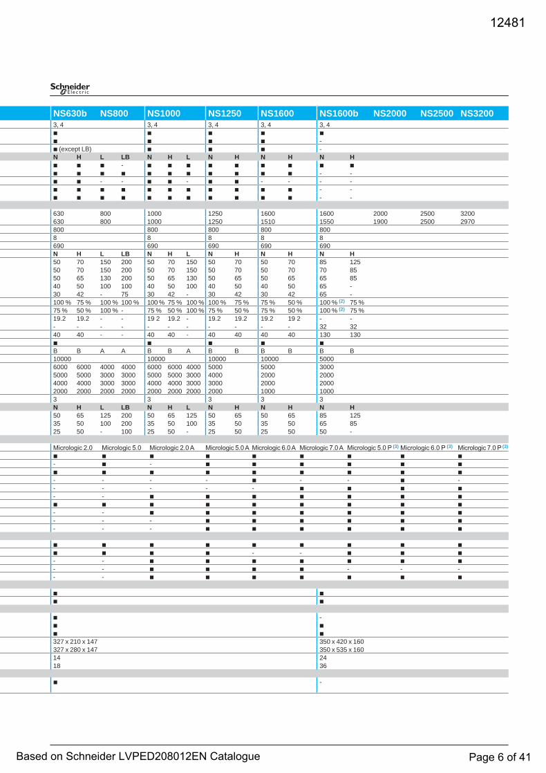
NS630b NS800 NS1000 NS1250 NS1600 NS1600b NS2000 NS2500 NS3200 3, 4 3, 4 3, 4 3, 4 3, 4
b b b b b b b b b -
b (except LB) b b b - N H L LB N H L N H N H N H
b b b - b b b b b b b b bb b b b b b b b b b b - -
b b - - b b - b b - - - - b b b b b b b b b b b - -
b b b b b b b b b b b - -
630 800 1000 1250 1600 1600 2000 2500 3200 630 800 1000 1250 1510 1550 1900 2500 2970
800 800 800 800 800 8 8 8 8 8 690 690 690 690 690
N H L LB N H L N H N H N H 22 2 50 70 150 200 50 70 150 50 70 50 70 85 125
1 50 70 150 200 50 70 150 50 70 50 70 70 8550 65 130 200 50 65 130 50 65 50 65 65 85
2 40 50 100 100 40 50 100 40 50 40 50 65 -30 42 - 75 30 42 - 30 42 30 42 65 -
100 % 75 % 100 % 100 % 100 % 75 % 100 % 100 % 75 % 75 % 50 % 100 % (2) 75 % 75 % 50 % 100 % - 75 % 50 % 100 % 75 % 50 % 75 % 50 % 100 % (2) 75 %
1 19.2 19.2 - - 19 2 19.2 - 19.2 19.2 19.2 19 2 - -- - - - - - - - - - - 32 32
1 40 40 - - 40 40 - 40 40 40 40 130 130 b b b b b
B B A A B B A B B B B B B 10000 10000 10000 10000 5000
2 6000 6000 4000 4000 6000 6000 4000 5000 5000 30005000 5000 3000 3000 5000 5000 3000 4000 2000 2000
2 4000 4000 3000 3000 4000 4000 3000 3000 2000 20002000 2000 2000 2000 2000 2000 2000 2000 1000 10003 3 3 3 3
N H L LB N H L N H N H N H 2 50 65 125 200 50 65 125 50 65 50 65 85 125
35 50 100 200 35 50 100 35 50 35 50 65 8525 50 - 100 25 50 - 25 50 25 50 50 -
Micrologic 2.0 Micrologic 5.0 Micrologic 2.0 A Micrologic 5.0 A Micrologic 6.0 A Micrologic 7.0 A Micrologic 5.0 P (3) Micrologic 6.0 P (3) Micrologic 7.0 P (3)
b b b b b b b b b - b - b b b b b b
b b b b b b b b b - - - - b - - b -
- - - - - b b b b - - b b b b b b b
b b b b b b b b b- - b b b b b b b- - - b b b b b b
- - - b b b b b b
b b b b b b b b b b b b b - - b b b
- - b b b b b b b - - b b b b - - -
- - b b b b b b b
b b b b
b - b b
b b 327 x 210 x 147 350 x 420 x 160
327 x 280 x 147 350 x 535 x 160 14 24
18 36
b -
12481
Based on Schneider LVPED208012EN Catalogue Page 6 of 41
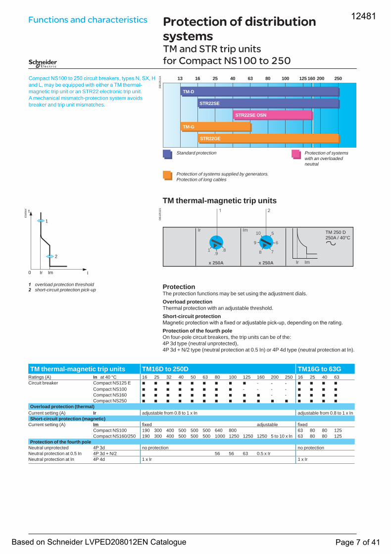
TM thermal-magnetic trip units
ProtectionThe protection functions may be set using the adjustment dials.Overload protectionThermal protection with an adjustable threshold.Short-circuit protectionMagnetic protection with a fixed or adjustable pick-up, depending on the rating.Protection of the fourth poleOn four-pole circuit breakers, the trip units can be of the:4P 3d type (neutral unprotected), 4P 3d + N/2 type (neutral protection at 0.5 In) or 4P 4d type (neutral protection at In).
Compact NS100 to 250 circuit breakers, types N, SX, H and L, may be equipped with either a TM thermal-magnetic trip unit or an STR22 electronic trip unit. A mechanical mismatch-protection system avoids breaker and trip unit mismatches.
DB
1051
15
ImIr
x 250A x 250A
1 .8.9
9
8 7
6
10 5
ImIr
TM 250 D250A / 40°C
Protection of distribution systemsTM and STR trip units for Compact NS100 to 250
DB
1051
14 13 16 25 40 63 80 100 125 200 250
TM-G
160
TM-D
STR22SE
STR22GE
STR22SE OSN
Standard protection
Protection of systems supplied by generators.Protection of long cables
Protection of systemswith an overloadedneutral
E58
564
I
t
0 Ir Im
2
1
1 overload protection threshold2 short-circuit protection pick-up
TM thermal-magnetic trip units TM16D to 250D TM16G to 63GRatings (A) In at 40 °C 16 25 32 40 50 63 80 100 125 160 200 250 16 25 40 63Circuit breaker Compact NS125 E b b b b b b b b b - - - b b b b
Compact NS100 b b b b b b b b - - - - b b b bCompact NS160 b b b b b b b b b b - - b b b bCompact NS250 b b b b b b b b b b b b b b b b
Overload protection (thermal)Current setting (A) Ir adjustable from 0.8 to 1 x In adjustable from 0.8 to 1 x InShort-circuit protection (magnetic)
Current setting (A) Im fixed adjustable fixedCompact NS100 190 300 400 500 500 500 640 800 63 80 80 125Compact NS160/250 190 300 400 500 500 500 1000 1250 1250 1250 5 to 10 x ln 63 80 80 125
Protection of the fourth poleNeutral unprotected 4P 3d no protection no protectionNeutral protection at 0.5 In 4P 3d + N/2 56 56 63 0.5 x IrNeutral protection at In 4P 4d 1 x Ir 1 x Ir
Functions and characteristics 12481
Based on Schneider LVPED208012EN Catalogue Page 7 of 41
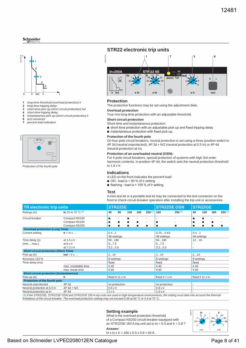
STR22 electronic trip units
ProtectionThe protection functions may be set using the adjustment dials.Overload protectionTrue rms long-time protection with an adjustable threshold.Short-circuit protectionShort-time and instantaneous protection:
short-time protection with an adjustable pick-up and fixed tripping delayinstantaneous protection with fixed pick-up.
Protection of the fourth poleOn four-pole circuit breakers, neutral protection is set using a three-position switch to 4P 3d (neutral unprotected), 4P 3d + N/2 (neutral protection at 0.5 In) or 4P 4d (neutral protection at In).Protection of an overloaded neutral (OSN):For 4-pole circuit breakers, special protection of systems with high 3rd order harmonic contents. In position 4P 4d, the switch sets the neutral protection threshold to 1.6 x Ir.
IndicationsA LED on the front indicates the percent load:
ON - load is > 90 % of Ir settingflashing - load is > 105 % of Ir setting.
TestA mini test kit or a portable test kit may be connected to the test connector on the front to check circuit-breaker operation after installing the trip unit or accessories.
bb
bb
1 long-time threshold (overload protection) Ir2 long-time tripping delay3 short-time pick-up (short-circuit protection) Isd4 short-time tripping delay5 instantaneous pick-up (short-circuit protection) Ii6 test connector7 percent load indication
DB
1037
50
DB
1037
49E
5871
1
4P 4d
Protection of the fourth pole
E25
979
x In
Ir
x Io
.8.85
.9.95
1
.88.93
.98
Io
.5
.63.7
.91
.8
TR electronic trip units STR22SE STR22SE OSN STR22GERatings (A) In 20 to 70 °C (1) 40 80 100 160 250 (1) 160 250 (1) 40 100 160 250 (1)
Circuit breaker Compact NS100 b - b - - - - b b - -Compact NS160 b b b b - b - b b b -Compact NS250 b b b b b b b b b b b
Overload protection (Long Time)Current setting Ir = In x … 0.4...1 0.25…0.63 0.4...1
48 settings 48 settings 48 settingsTime delay (s) at 1.5 x Ir 90...180 90...180 12…15(min.…max.) at 6 x Ir 5...7.5 5...7.5 -
at 7.2 x Ir 3.2...5.0 3.2...5.0 -Short-circuit protection (Short Time)
Pick-up (A) Isd = Ir x … 2...10 2...10 2...10Accuracy ±15 % 8 settings 8 settings 8 settingsTime delay (ms) fixed fixed fixed
max. resettable time y 40 y 40 y 40max. break time y 60 y 60 y 60
Short-circuit protection (Instantaneous)Pick-up (A) Ii fixed u 11 x In fixed u 7 x In fixed u 11 x InProtection of the fourth pole
Neutral unprotected 4P 3d no protection no protection -Neutral protection at 0.5 In 4P 3d + N/2 0.5 x Ir 0.8 x Ir -Neutral protection at In 4P 4d 1 x Ir 1.6 x Ir -(1) If the STR22SE, STR22SE OSN and STR22GE 250 A trip units are used in high-temperature environments, the setting must take into account the thermal limitations of the circuit breaker. The overload protection setting may not exceed 0.95 at 60 °C or 0.9 at 70 °C.
Setting exampleWhat is the overload-protection threshold of a Compact NS250 circuit breaker equipped with an STR22SE 160 A trip unit set to Io = 0.5 and Ir = 0.8 ?Answer:In x Io x Ir = 160 x 0.5 x 0.8 = 64 A.
12481
Based on Schneider LVPED208012EN Catalogue Page 8 of 41
DB
1051
16 60 250 400 500 60040
STR23SE 0SN
STR23SE / STR53UE
STR23SE / STR53UE
STR23SV / STR53SV
Protection of systems with anoverloaded neutral
Standard protection with selectivity
Protection of systems suppliedby generators.Protection of long cables
Protection of systems U > 525 V
Protection of distribution systemsSTR trip units for Compact NS400 to 630
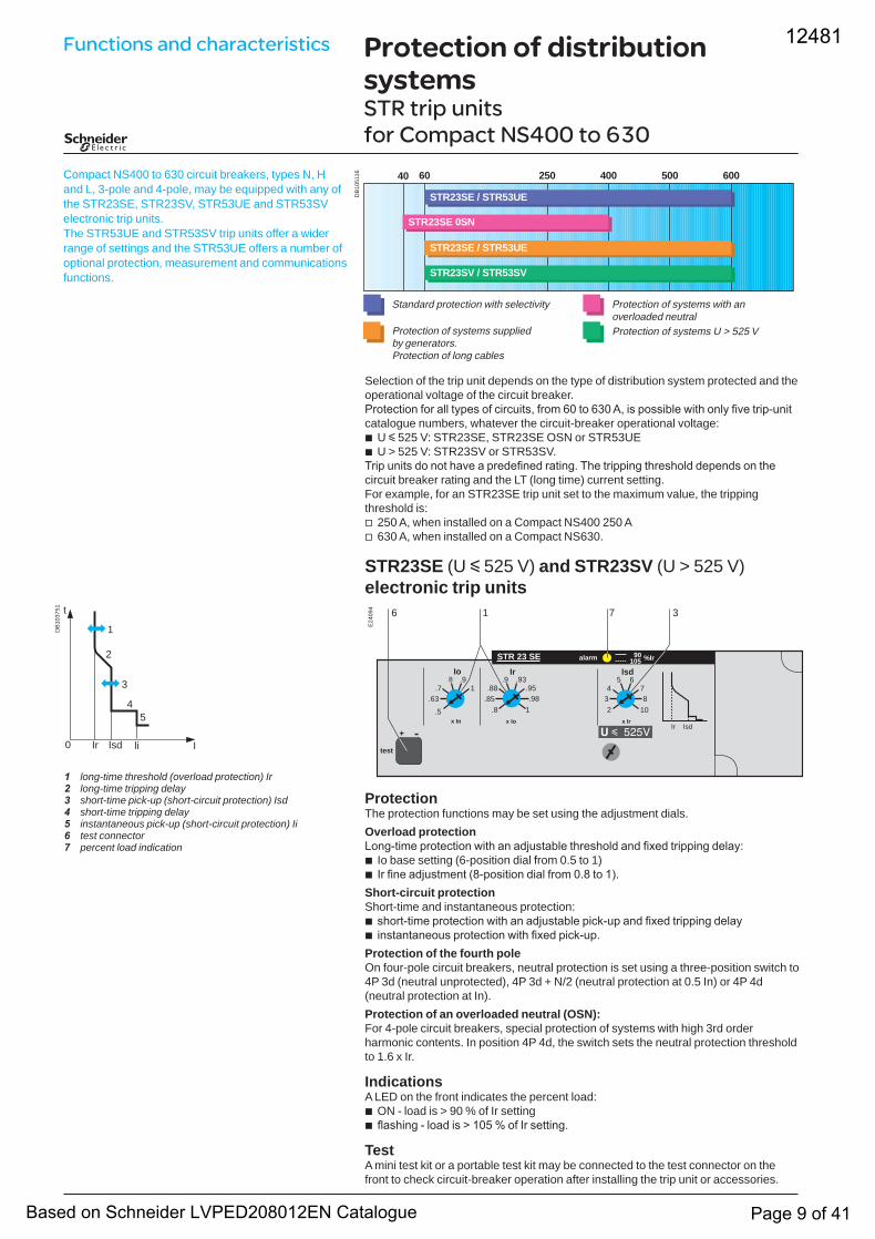
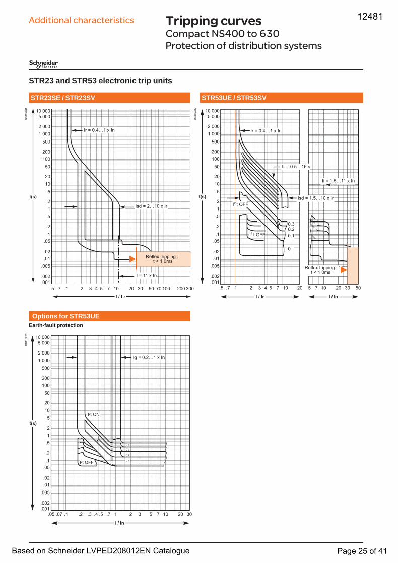
Compact NS400 to 630 circuit breakers, types N, H and L, 3-pole and 4-pole, may be equipped with any of the STR23SE, STR23SV, STR53UE and STR53SV electronic trip units.The STR53UE and STR53SV trip units offer a wider range of settings and the STR53UE offers a number of optional protection, measurement and communications functions.
Selection of the trip unit depends on the type of distribution system protected and the operational voltage of the circuit breaker.Protection for all types of circuits, from 60 to 630 A, is possible with only five trip-unit catalogue numbers, whatever the circuit-breaker operational voltage:
U y 525 V: STR23SE, STR23SE OSN or STR53UEU > 525 V: STR23SV or STR53SV.
Trip units do not have a predefined rating. The tripping threshold depends on the circuit breaker rating and the LT (long time) current setting.For example, for an STR23SE trip unit set to the maximum value, the tripping threshold is:
250 A, when installed on a Compact NS400 250 A630 A, when installed on a Compact NS630.
STR23SE (U y 525 V) and STR23SV (U > 525 V) electronic trip units
ProtectionThe protection functions may be set using the adjustment dials.Overload protectionLong-time protection with an adjustable threshold and fixed tripping delay:
Io base setting (6-position dial from 0.5 to 1)Ir fine adjustment (8-position dial from 0.8 to 1).
Short-circuit protectionShort-time and instantaneous protection:
short-time protection with an adjustable pick-up and fixed tripping delayinstantaneous protection with fixed pick-up.
Protection of the fourth poleOn four-pole circuit breakers, neutral protection is set using a three-position switch to 4P 3d (neutral unprotected), 4P 3d + N/2 (neutral protection at 0.5 In) or 4P 4d (neutral protection at In).Protection of an overloaded neutral (OSN):For 4-pole circuit breakers, special protection of systems with high 3rd order harmonic contents. In position 4P 4d, the switch sets the neutral protection threshold to 1.6 x Ir.
IndicationsA LED on the front indicates the percent load:
ON - load is > 90 % of Ir settingflashing - load is > 105 % of Ir setting.
TestA mini test kit or a portable test kit may be connected to the test connector on the front to check circuit-breaker operation after installing the trip unit or accessories.
bb
vv
bb
bb
bb
1 long-time threshold (overload protection) Ir2 long-time tripping delay3 short-time pick-up (short-circuit protection) Isd4 short-time tripping delay5 instantaneous pick-up (short-circuit protection) Ii6 test connector7 percent load indication
E24
094
IsdIr
STR 23 SEIr
x Io
Io
-test
+
90105 %Iralarm
x In
6 1 37
.5
.63.7
.91
.8.85
.9.95
1
.88.93
.98
8
234
5 678
10
Isd
x Ir
DB
1037
51 t
Isd I0 Ir li
1
2
3
45
Functions and characteristics 12481
Based on Schneider LVPED208012EN Catalogue Page 9 of 41
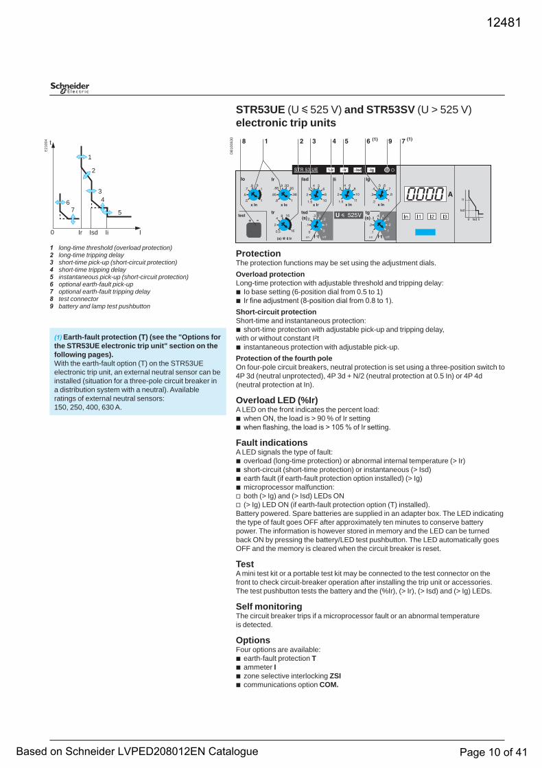
STR53UE (U y 525 V) and STR53SV (U > 525 V) electronic trip units
ProtectionThe protection functions may be set using the adjustment dials.Overload protectionLong-time protection with adjustable threshold and tripping delay:
Io base setting (6-position dial from 0.5 to 1)Ir fine adjustment (8-position dial from 0.8 to 1).
Short-circuit protectionShort-time and instantaneous protection:
short-time protection with adjustable pick-up and tripping delay,with or without constant I²t
instantaneous protection with adjustable pick-up.Protection of the fourth poleOn four-pole circuit breakers, neutral protection is set using a three-position switch to 4P 3d (neutral unprotected), 4P 3d + N/2 (neutral protection at 0.5 In) or 4P 4d (neutral protection at In).
Overload LED (%Ir)A LED on the front indicates the percent load:
when ON, the load is > 90 % of Ir settingwhen flashing, the load is > 105 % of Ir setting.
Fault indicationsA LED signals the type of fault:
overload (long-time protection) or abnormal internal temperature (> Ir)short-circuit (short-time protection) or instantaneous (> Isd)earth fault (if earth-fault protection option installed) (> Ig)microprocessor malfunction:both (> Ig) and (> Isd) LEDs ON(> Ig) LED ON (if earth-fault protection option (T) installed).
Battery powered. Spare batteries are supplied in an adapter box. The LED indicating the type of fault goes OFF after approximately ten minutes to conserve battery power. The information is however stored in memory and the LED can be turned back ON by pressing the battery/LED test pushbutton. The LED automatically goes OFF and the memory is cleared when the circuit breaker is reset.
TestA mini test kit or a portable test kit may be connected to the test connector on the front to check circuit-breaker operation after installing the trip unit or accessories.The test pushbutton tests the battery and the (%Ir), (> Ir), (> Isd) and (> Ig) LEDs.
Self monitoringThe circuit breaker trips if a microprocessor fault or an abnormal temperature is detected.
OptionsFour options are available:
earth-fault protection Tammeter Izone selective interlocking ZSIcommunications option COM.
bb
b
b
bb
bbbbvv
bbbb
1 long-time threshold (overload protection)2 long-time tripping delay3 short-time pick-up (short-circuit protection)4 short-time tripping delay5 instantaneous pick-up (short-circuit protection)6 optional earth-fault pick-up7 optional earth-fault tripping delay8 test connector9 battery and lamp test pushbutton
(1) Earth-fault protection (T) (see the "Options for the STR53UE electronic trip unit" section on the following pages).With the earth-fault option (T) on the STR53UE electronic trip unit, an external neutral sensor can be installed (situation for a three-pole circuit breaker in a distribution system with a neutral). Available ratings of external neutral sensors: 150, 250, 400, 630 A.
E21
004 t
0 Ir Isd Ii
5
43
2
1
67
ID
B10
0630
12481
Based on Schneider LVPED208012EN Catalogue Page 10 of 41
Protection of distribution systemsSTR trip units for Compact NS400 to 630 (cont.)
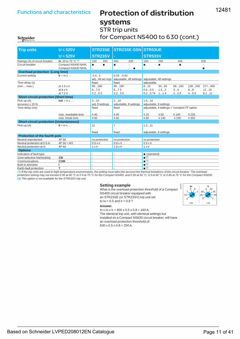
Setting exampleWhat is the overload-protection threshold of a Compact NS400 circuit breaker equipped with an STR23SE (or STR23SV) trip unit set to Io = 0.5 and Ir = 0.8 ?Answer.In x Io x Ir = 400 x 0.5 x 0.8 = 160 A.The identical trip unit, with identical settings but installed on a Compact NS630 circuit breaker, will have an overload-protection threshold of:630 x 0.5 x 0.8 = 250 A.
E25
979
x In
Ir
x Io
.8.85
.9.95
1
.88.93
.98
Io
.5
.63.7
.91
.8
Trip units U y 525V STR23SE STR23SE OSN STR53UEU > 525V STR23SV - STR53SV
Ratings (A) of circuit breaker In 20 to 70 °C (1) 150 250 400 630 150 250 400 630Circuit breaker Compact NS400 N/H/L b b b - b b b -
Compact NS630 N/H/L - - - b - - - bOverload protection (Long time)
Current setting Ir = In x … 0.4...1 0.25…0.63adj., 48 set ings adjustable, 48 settings adjustable, 48 settings
Time delay (s) fixed fixed adjustable(min.…max.) at 1.5 x Ir 90...180 90...180 8...15 34...50 69...100 138...200 277...400
at 6 x Ir 5...7.5 5...7 5 0.4...0.5 1.5...2 3...4 6...8 12...16at 7.2 Ir 3.2...5 0 3.2.. 5.0 0.2...0.74 1...1.4 2...2.8 4...5.5 8.2...11
Short-circuit protection (Short time)Pick-up (A) Isd = Ir x … 2...10 2...10 1.5...10accuracy ± 15 % adj, 8 settings adjustable, 8 settings adjustable, 8 settingsTime delay (ms) fixed fixed adjustable, 4 settings + "constant I2t" option
max. resettable time y 40 y 40 y 15 y 60 y 140 y 230max. break time y 60 y 60 y 60 y 140 y 230 y 350
Short-circuit protection (instantaneous)Pick-up (A) Ii = In x … 11 7 1.5...11
fixed fixed adjustable, 8 settingsProtection of the fourth pole
Neutral unprotected 4P 3d no protection no protection no protectionNeutral protection at 0.5 In 4P 3d + N/2 0.5 x Ir 0.8 x Ir 0.5 x IrNeutral protection at In 4P 4d 1 x Ir 1.6 x Ir 1 x IrOptions
Indication of fault type - - b (standard)Zone selective interlocking ZSI - - b (2)
Communications COM - - b (2)
Built-in ammeter I - - b (2)
Earth-fault protection T - - b (2)
(1) If the trip units are used in high-temperature environments, the setting must take into account the thermal limitations of the circuit breaker. The overload protection setting may not exceed 0.95 at 60 °C or 0.9 at 70 °C for the Compact NS400, and 0.95 at 50 °C, 0.9 at 60 °C or 0.85 at 70 °C for the Compact NS630.(2) This option is not available for the STR53SV trip unit.
Functions and characteristics 12481
Based on Schneider LVPED208012EN Catalogue Page 11 of 41
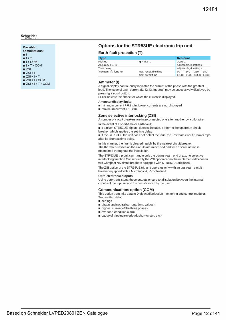
Options for the STR53UE electronic trip unitEarth-fault protection (T)
Ammeter (I)A digital display continuously indicates the current of the phase with the greatest load. The value of each current (I1, I2, I3, Ineutral) may be successively displayed by pressing a scroll button.LEDs indicate the phase for which the current is displayed.Ammeter display limits:
minimum current u 0.2 x In. Lower currents are not displayedmaximum current y 10 x In.
Zone selective interlocking (ZSI)A number of circuit breakers are interconnected one after another by a pilot wire.In the event of a short-time or earth fault:
if a given STR53UE trip unit detects the fault, it informs the upstream circuit breaker, which applies the set time delay
if the STR53UE trip unit does not detect the fault, the upstream circuit breaker trips after its shortest time delay.In this manner, the fault is cleared rapidly by the nearest circuit breaker. The thermal stresses on the circuits are minimised and time discrimination is maintained throughout the installation.The STR53UE trip unit can handle only the downstream end of a zone selective interlocking function.Consequently,the ZSI option cannot be implemented between two Compact NS circuit breakers equipped with STRE53UE trip units.The ZSI option of the STR53UE trip unit operates only with an upstream circuit breaker equipped with a Micrologic A, P control unit.Opto-electronic outputsUsing opto-transistors, these outputs ensure total isolation between the internal circuits of the trip unit and the circuits wired by the user.
Communications option (COM)This option transmits data to Digipact distribution monitoring and control modules.Transmitted data:
settingsphase and neutral currents (rms values)highest current of the three phasesoverload-condition alarmcause of tripping (overload, short-circuit, etc.).
bb
b
b
bbbbb
Possiblecombinations:
II + T I + COM I + T + COM ZSIZSI + IZSI + I + T ZSI + I + COM ZSI + I + T + COM
bbbbbbbbb
Type ResidualPick-up Ig = In x … 0.2 to 1Accuracy ±15 % adjustable, 8 settingsTime delay adjustable, 4 settings"constant I2t" func ion max. resettable time 60 140 230 350
max. break time y 140 y 230 y 350 y 500
12481
Based on Schneider LVPED208012EN Catalogue Page 12 of 41
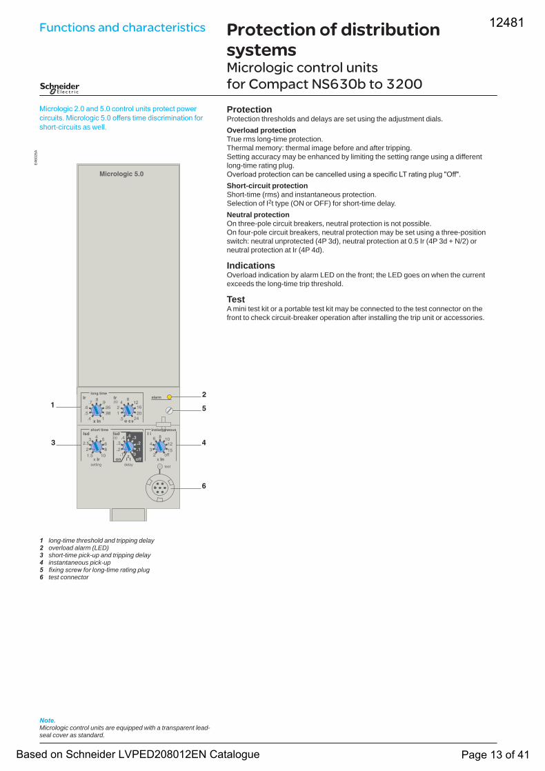
1 long-time threshold and tripping delay2 overload alarm (LED)3 short-time pick-up and tripping delay4 instantaneous pick-up5 fixing screw for long-time rating plug6 test connector
ProtectionProtection thresholds and delays are set using the adjustment dials.Overload protectionTrue rms long-time protection.Thermal memory: thermal image before and after tripping.Setting accuracy may be enhanced by limiting the setting range using a different long-time rating plug.Overload protection can be cancelled using a specific LT rating plug "Off".Short-circuit protectionShort-time (rms) and instantaneous protection.Selection of I2t type (ON or OFF) for short-time delay.Neutral protectionOn three-pole circuit breakers, neutral protection is not possible.On four-pole circuit breakers, neutral protection may be set using a three-position switch: neutral unprotected (4P 3d), neutral protection at 0.5 Ir (4P 3d + N/2) or neutral protection at Ir (4P 4d).
IndicationsOverload indication by alarm LED on the front; the LED goes on when the current exceeds the long-time trip threshold.
TestA mini test kit or a portable test kit may be connected to the test connector on the front to check circuit-breaker operation after installing the trip unit or accessories.
Micrologic 2.0 and 5.0 control units protect power circuits. Micrologic 5.0 offers time discrimination for short-circuits as well.
Note.Micrologic control units are equipped with a transparent lead-seal cover as standard.
Protection of distribution systemsMicrologic control units for Compact NS630b to 3200
E46
026A
Functions and characteristics 12481
Based on Schneider LVPED208012EN Catalogue Page 13 of 41
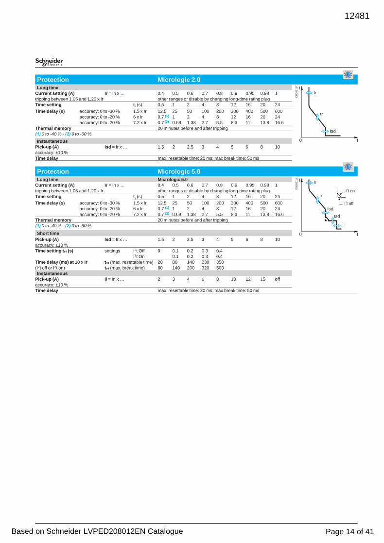
Protection Micrologic 2.0Long time
Current setting (A) Ir = In x … 0.4 0.5 0.6 0.7 0.8 0.9 0.95 0.98 1tripping between 1.05 and 1.20 x Ir other ranges or disable by changing long-time rating plugTime setting tr (s) 0.5 1 2 4 8 12 16 20 24 Time delay (s) accuracy: 0 to -30 % 1.5 x Ir 12.5 25 50 100 200 300 400 500 600
accuracy: 0 to -20 % 6 x Ir 0.7 (1) 1 2 4 8 12 16 20 24accuracy: 0 to -20 % 7.2 x Ir 0.7 (2) 0.69 1.38 2.7 5.5 8.3 11 13.8 16.6
Thermal memory 20 minutes before and after tripping(1) 0 to -40 % - (2) 0 to -60 %Instantaneous
Pick-up (A) Isd = Ir x … 1.5 2 2.5 3 4 5 6 8 10accuracy: ±10 %Time delay max. resettable time: 20 ms; max break time: 50 ms
Protection Micrologic 5.0Long time Micrologic 5.0
Current setting (A) Ir = In x … 0.4 0.5 0.6 0.7 0.8 0.9 0.95 0.98 1tripping between 1.05 and 1.20 x Ir other ranges or disable by changing long-time rating plugTime setting tr (s) 0.5 1 2 4 8 12 16 20 24Time delay (s) accuracy: 0 to -30 % 1.5 x Ir 12.5 25 50 100 200 300 400 500 600
accuracy: 0 to -20 % 6 x Ir 0.7 (1) 1 2 4 8 12 16 20 24accuracy: 0 to -20 % 7.2 x Ir 0.7 (2) 0.69 1.38 2.7 5.5 8.3 11 13.8 16.6
Thermal memory 20 minutes before and after tripping(1) 0 to -40 % - (2) 0 to -60 %
Short timePick-up (A) Isd = Ir x … 1.5 2 2.5 3 4 5 6 8 10accuracy: ±10 %Time setting tsd (s) settings I2t Off 0 0.1 0.2 0.3 0.4
I2t On 0.1 0.2 0.3 0.4Time delay (ms) at 10 x Ir tsd (max. resettable time) 20 80 140 230 350(I2t off or I2t on) tsd (max. break time) 80 140 200 320 500Instantaneous
Pick-up (A) Ii = In x … 2 3 4 6 8 10 12 15 offaccuracy: ±10 %Time delay max. resettable time: 20 ms; max break time: 50 ms
DB
1051
17
0 I
tIr
tr
Isd
DB
1051
18
Ir
tr
Isd
Ii
0 I
t
tsd
I2t off
I2t on
12481
Based on Schneider LVPED208012EN Catalogue Page 14 of 41
Protection of distribution systemsMicrologic A control units for Compact NS630b to 3200 (cont.)
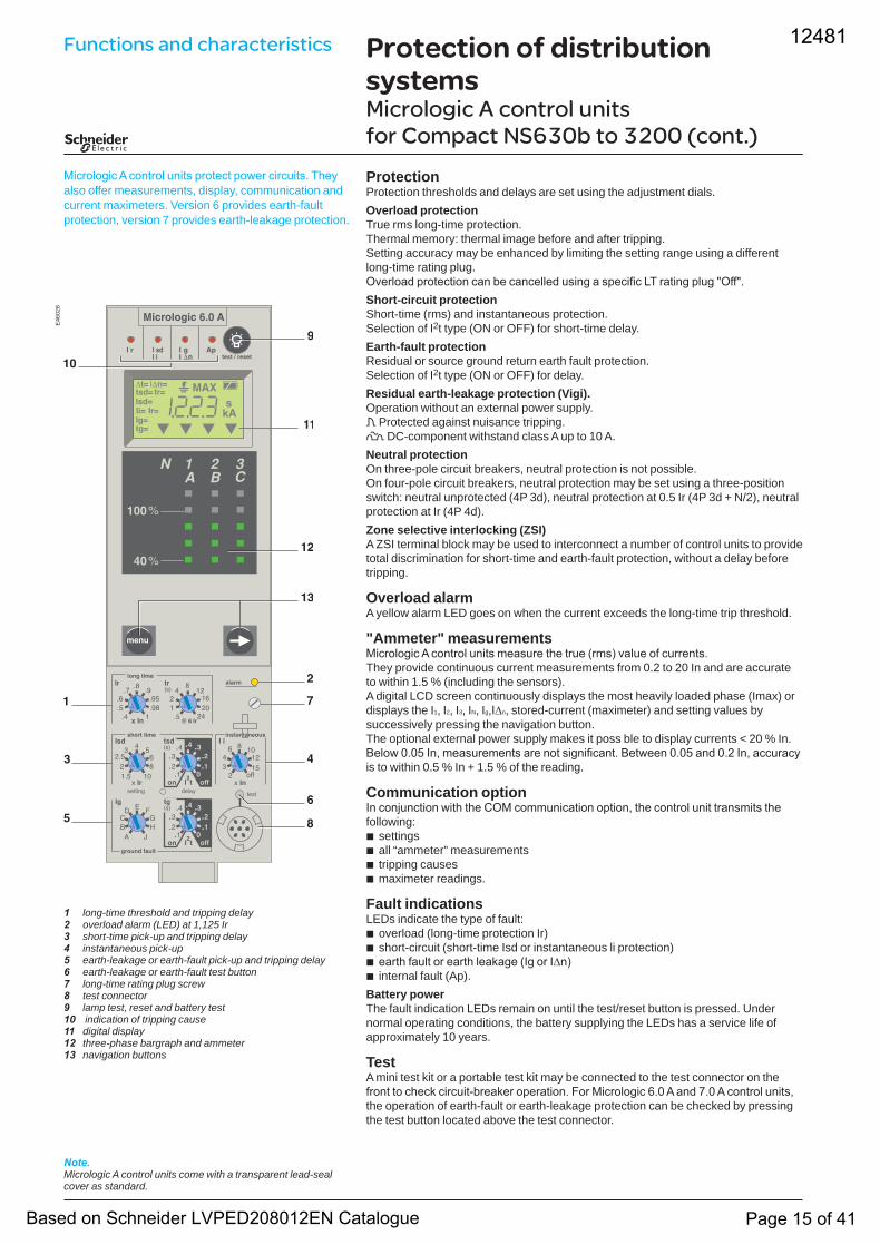
1 long-time threshold and tripping delay2 overload alarm (LED) at 1,125 Ir3 short-time pick-up and tripping delay4 instantaneous pick-up5 earth-leakage or earth-fault pick-up and tripping delay6 earth-leakage or earth-fault test button7 long-time rating plug screw8 test connector9 lamp test, reset and battery test10 indication of tripping cause11 digital display12 three-phase bargraph and ammeter13 navigation buttons
Micrologic A control units protect power circuits. They also offer measurements, display, communication and current maximeters. Version 6 provides earth-fault protection, version 7 provides earth-leakage protection.
Note.Micrologic A control units come with a transparent lead-seal cover as standard.
ProtectionProtection thresholds and delays are set using the adjustment dials.Overload protectionTrue rms long-time protection.Thermal memory: thermal image before and after tripping.Setting accuracy may be enhanced by limiting the setting range using a different long-time rating plug.Overload protection can be cancelled using a specific LT rating plug "Off".Short-circuit protectionShort-time (rms) and instantaneous protection.Selection of I2t type (ON or OFF) for short-time delay.Earth-fault protectionResidual or source ground return earth fault protection.Selection of I2t type (ON or OFF) for delay.Residual earth-leakage protection (Vigi).Operation without an external power supply. q Protected against nuisance tripping. k DC-component withstand class A up to 10 A.Neutral protectionOn three-pole circuit breakers, neutral protection is not possible.On four-pole circuit breakers, neutral protection may be set using a three-position switch: neutral unprotected (4P 3d), neutral protection at 0.5 Ir (4P 3d + N/2), neutral protection at Ir (4P 4d).Zone selective interlocking (ZSI)A ZSI terminal block may be used to interconnect a number of control units to provide total discrimination for short-time and earth-fault protection, without a delay before tripping.
Overload alarmA yellow alarm LED goes on when the current exceeds the long-time trip threshold.
"Ammeter" measurementsMicrologic A control units measure the true (rms) value of currents.They provide continuous current measurements from 0.2 to 20 In and are accurate to within 1.5 % (including the sensors).A digital LCD screen continuously displays the most heavily loaded phase (Imax) or displays the I1, I2, I3, IN, Ig,I∆n, stored-current (maximeter) and setting values by successively pressing the navigation button.The optional external power supply makes it poss ble to display currents < 20 % In.Below 0.05 In, measurements are not significant. Between 0.05 and 0.2 In, accuracy is to within 0.5 % In + 1.5 % of the reading.
Communication optionIn conjunction with the COM communication option, the control unit transmits the following:
settingsall “ammeter” measurementstripping causesmaximeter readings.
Fault indicationsLEDs indicate the type of fault:
overload (long-time protection Ir)short-circuit (short-time Isd or instantaneous li protection)earth fault or earth leakage (Ig or I∆n)internal fault (Ap).
Battery powerThe fault indication LEDs remain on until the test/reset button is pressed. Under normal operating conditions, the battery supplying the LEDs has a service life of approximately 10 years.
TestA mini test kit or a portable test kit may be connected to the test connector on the front to check circuit-breaker operation. For Micrologic 6.0 A and 7.0 A control units, the operation of earth-fault or earth-leakage protection can be checked by pressing the test button located above the test connector.
bbbb
bbbb
E46
028
Functions and characteristics 12481
Based on Schneider LVPED208012EN Catalogue Page 15 of 41
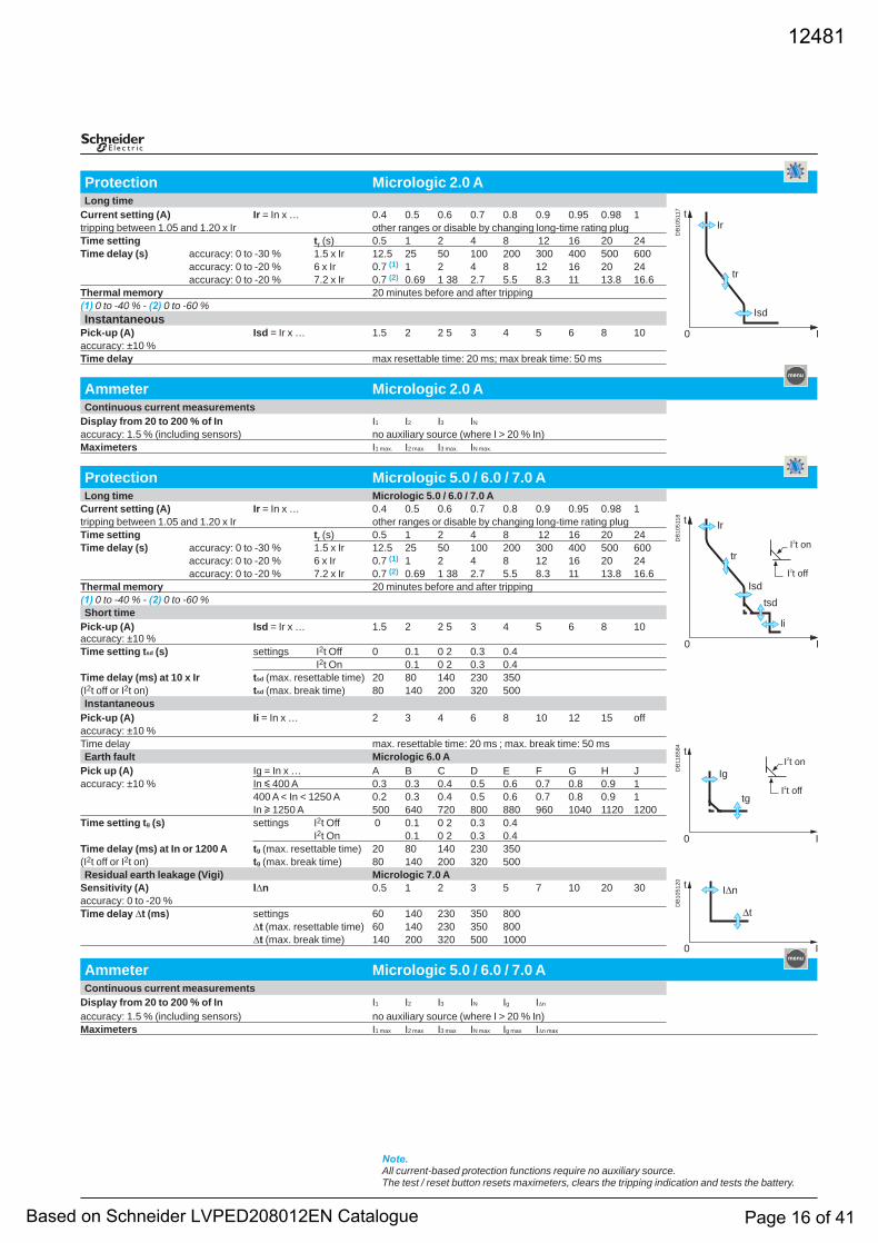
Protection Micrologic 2.0 ALong time
Current setting (A) Ir = In x … 0.4 0.5 0.6 0.7 0.8 0.9 0.95 0.98 1tripping between 1.05 and 1.20 x Ir other ranges or disable by changing long-time rating plugTime setting tr (s) 0.5 1 2 4 8 12 16 20 24 Time delay (s) accuracy: 0 to -30 % 1.5 x Ir 12.5 25 50 100 200 300 400 500 600
accuracy: 0 to -20 % 6 x Ir 0.7 (1) 1 2 4 8 12 16 20 24 accuracy: 0 to -20 % 7.2 x Ir 0.7 (2) 0.69 1 38 2.7 5.5 8.3 11 13.8 16.6
Thermal memory 20 minutes before and after tripping(1) 0 to -40 % - (2) 0 to -60 %Instantaneous
Pick-up (A) Isd = Ir x … 1.5 2 2 5 3 4 5 6 8 10accuracy: ±10 %Time delay max resettable time: 20 ms; max break time: 50 ms
Ammeter Micrologic 2.0 AContinuous current measurements
Display from 20 to 200 % of In I1 I2 I3 IN
accuracy: 1.5 % (including sensors) no auxiliary source (where I > 20 % In)Maximeters I1 max. I2 max. I3 max. IN max.
Protection Micrologic 5.0 / 6.0 / 7.0 ALong time Micrologic 5.0 / 6.0 / 7.0 A
Current setting (A) Ir = In x … 0.4 0.5 0.6 0.7 0.8 0.9 0.95 0.98 1tripping between 1.05 and 1.20 x Ir other ranges or disable by changing long-time rating plugTime setting tr (s) 0.5 1 2 4 8 12 16 20 24 Time delay (s) accuracy: 0 to -30 % 1.5 x Ir 12.5 25 50 100 200 300 400 500 600
accuracy: 0 to -20 % 6 x Ir 0.7 (1) 1 2 4 8 12 16 20 24accuracy: 0 to -20 % 7.2 x Ir 0.7 (2) 0.69 1 38 2.7 5.5 8.3 11 13.8 16.6
Thermal memory 20 minutes before and after tripping(1) 0 to -40 % - (2) 0 to -60 %Short time
Pick-up (A)accuracy: ±10 %
Isd = Ir x … 1.5 2 2 5 3 4 5 6 8 10
Time setting tsd (s) settings I2t Off 0 0.1 0 2 0.3 0.4 I2t On 0.1 0 2 0.3 0.4
Time delay (ms) at 10 x Ir tsd (max. resettable time) 20 80 140 230 350(I2t off or I2t on) tsd (max. break time) 80 140 200 320 500Instantaneous
Pick-up (A) Ii = In x … 2 3 4 6 8 10 12 15 offaccuracy: ±10 %Time delay max. resettable time: 20 ms ; max. break time: 50 msEarth fault Micrologic 6.0 A
Pick up (A) Ig = In x … A B C D E F G H Jaccuracy: ±10 % In y 400 A 0.3 0.3 0.4 0.5 0.6 0.7 0.8 0.9 1
400 A < In < 1250 A 0.2 0.3 0.4 0.5 0.6 0.7 0.8 0.9 1In u 1250 A 500 640 720 800 880 960 1040 1120 1200
Time setting tg (s) settings I2t Off 0 0.1 0 2 0.3 0.4I2t On 0.1 0 2 0.3 0.4
Time delay (ms) at In or 1200 A tg (max. resettable time) 20 80 140 230 350(I2t off or I2t on) tg (max. break time) 80 140 200 320 500Residual earth leakage (Vigi) Micrologic 7.0 A
Sensitivity (A) I∆n 0.5 1 2 3 5 7 10 20 30accuracy: 0 to -20 % Time delay ∆t (ms) settings 60 140 230 350 800
∆t (max. resettable time) 60 140 230 350 800∆t (max. break time) 140 200 320 500 1000
Ammeter Micrologic 5.0 / 6.0 / 7.0 A Continuous current measurements
Display from 20 to 200 % of In I1 I2 I3 IN Ig I∆n
accuracy: 1.5 % (including sensors) no auxiliary source (where I > 20 % In)Maximeters I1 max I2 max I3 max IN max Ig max I∆n max
Note.All current-based protection functions require no auxiliary source. The test / reset button resets maximeters, clears the tripping indication and tests the battery.
DB
1051
17
0 I
tIr
tr
Isd
DB
1051
18
Ir
tr
Isd
Ii
0 I
t
tsd
I2t off
I2t on
DB
1185
84
0 I
t
Ig
tgI2t off
I2t on
DB
1051
20
0 I
t I∆n
∆t
12481
Based on Schneider LVPED208012EN Catalogue Page 16 of 41
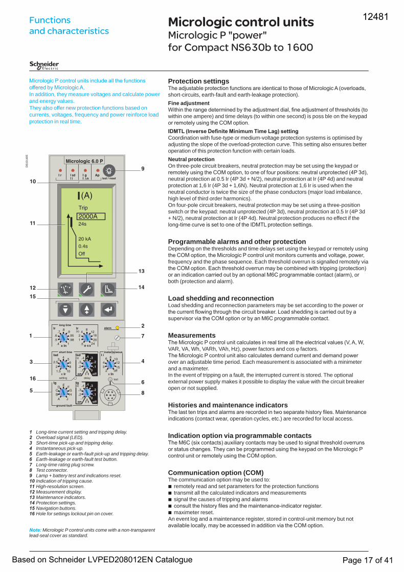
Micrologic control unitsMicrologic P "power" for Compact NS630b to 1600
Micrologic P control units include all the functions offered by Micrologic A.In addition, they measure voltages and calculate power and energy values.They also offer new protection functions based on currents, voltages, frequency and power reinforce load protection in real time.
Long-time current setting and tripping delay.Overload signal (LED).Short-time pick-up and tripping delay.Instantaneous pick-up.Earth-leakage or earth-fault pick-up and tripping delay.Earth-leakage or earth-fault test button.Long-time rating plug screw.Test connector.Lamp + battery test and indications reset.Indication of tripping cause.High-resolution screen.Measurement display.Maintenance indicators.Protection settings.Navigation buttons.Hole for settings lockout pin on cover.
Note: Micrologic P control units come with a non-transparent lead-seal cover as standard.
12345678910111213141516
Protection settingsThe adjustable protection functions are identical to those of Micrologic A (overloads, short-circuits, earth-fault and earth-leakage protection).Fine adjustmentWithin the range determined by the adjustment dial, fine adjustment of thresholds (to within one ampere) and time delays (to within one second) is poss ble on the keypad or remotely using the COM option.IDMTL (Inverse Definite Minimum Time Lag) settingCoordination with fuse-type or medium-voltage protection systems is optimised by adjusting the slope of the overload-protection curve. This setting also ensures better operation of this protection function with certain loads.Neutral protectionOn three-pole circuit breakers, neutral protection may be set using the keypad or remotely using the COM option, to one of four positions: neutral unprotected (4P 3d), neutral protection at 0.5 Ir (4P 3d + N/2), neutral protection at Ir (4P 4d) and neutral protection at 1,6 Ir (4P 3d + 1,6N). Neutral protection at 1,6 Ir is used when the neutral conductor is twice the size of the phase conductors (major load imbalance, high level of third order harmonics).On four-pole circuit breakers, neutral protection may be set using a three-position switch or the keypad: neutral unprotected (4P 3d), neutral protection at 0.5 Ir (4P 3d + N/2), neutral protection at Ir (4P 4d). Neutral protection produces no effect if the long-time curve is set to one of the IDMTL protection settings.
Programmable alarms and other protectionDepending on the thresholds and time delays set using the keypad or remotely using the COM option, the Micrologic P control unit monitors currents and voltage, power, frequency and the phase sequence. Each threshold overrun is signalled remotely via the COM option. Each threshold overrun may be combined with tripping (protection) or an indication carried out by an optional M6C programmable contact (alarm), or both (protection and alarm).
Load shedding and reconnectionLoad shedding and reconnection parameters may be set according to the power or the current flowing through the circuit breaker. Load shedding is carried out by a supervisor via the COM option or by an M6C programmable contact.
MeasurementsThe Micrologic P control unit calculates in real time all the electrical values (V, A, W, VAR, VA, Wh, VARh, VAh, Hz), power factors and cos j factors.The Micrologic P control unit also calculates demand current and demand power over an adjustable time period. Each measurement is associated with a minimeter and a maximeter.In the event of tripping on a fault, the interrupted current is stored. The optional external power supply makes it possible to display the value with the circuit breaker open or not supplied.
Histories and maintenance indicatorsThe last ten trips and alarms are recorded in two separate history files. Maintenance indications (contact wear, operation cycles, etc.) are recorded for local access.
Indication option via programmable contactsThe M6C (six contacts) auxiliary contacts may be used to signal threshold overruns or status changes. They can be programmed using the keypad on the Micrologic P control unit or remotely using the COM option.
Communication option (COM)The communication option may be used to:
remotely read and set parameters for the protection functionstransmit all the calculated indicators and measurementssignal the causes of tripping and alarmsconsult the history files and the maintenance-indicator register.maximeter reset.
An event log and a maintenance register, stored in control-unit memory but not available locally, may be accessed in addition via the COM option.
bbbbb
DB
1014
85Functions and characteristics
12481
Based on Schneider LVPED208012EN Catalogue Page 17 of 41
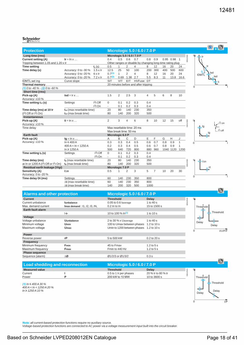
Protection Micrologic 5.0 / 6.0 / 7.0 P +Long time (rms) Micrologic 5.0 / 6.0 / 7.0 P
DB
1123
82
Current setting (A) Ir = In x … 0.4 0.5 0.6 0.7 0.8 0.9 0.95 0.98 1Tripping between 1.05 and 1.20 x Ir Other ranges or disable by changing long-time rating plug Time setting tr (s) 0.5 1 2 4 8 12 16 20 24Time delay (s) Accuracy: 0 to -30 % 1.5 x Ir 12.5 25 50 100 200 300 400 500 600
Accuracy: 0 to -20 % 6 x Ir 0.7(1) 1 2 4 8 12 16 20 24Accuracy: 0 to -20 % 7.2 x Ir 0.7(2) 0.69 1.38 2.7 5.5 8.3 11 13.8 16.6
IDMTL set ing Curve slope SIT VIT EIT HVFuse DTThermal memory 20 minutes before and after tripping(1) 0 to -40 % - (2) 0 to -60 %Short time (rms)
Pick-up (A) Isd = Ir x … 1.5 2 2.5 3 4 5 6 8 10Accuracy: ±10 %Time setting tsd (s) Settings I2t Off 0 0.1 0.2 0.3 0.4
I2t On - 0.1 0.2 0.3 0.4Time delay (ms) at 10 Ir tsd (max resettable time) 20 80 140 230 350(I2t Off or I2t On) tsd (max break time) 80 140 200 320 500Instantaneous
Pick-up (A) Ii = In x … 2 3 4 6 8 10 12 15 off
DB
1123
83
Accuracy: ±10 %Time delay Max resettable time: 20 ms
Max break time: 50 msEarth fault Micrologic 6.0 P
Pick-up (A)Accuracy: ±10 %
Ig = In x … A B C D E F G H JIn y 400 A 0.3 0.3 0.4 0.5 0.6 0.7 0.8 0.9 1400 A < In < 1250 A 0.2 0.3 0.4 0.5 0.6 0.7 0.8 0.9 1In u 1250 A 500 640 720 800 880 960 1040 1120 1200
Time setting tg (s) Settings I2t Off 0 0.1 0.2 0.3 0.4I2t On - 0.1 0.2 0.3 0.4
Time delay (ms) tg (max resettable time) 20 80 140 230 350
DB
1123
84
at In or 1200 A (I2t Off or I2t On) tg (max break time) 80 140 200 320 500Residual earth leakage (Vigi) Micrologic 7.0 P
Sensitivity (A)Accuracy: 0 to -20 %
I∆n 0.5 1 2 3 5 7 10 20 30
Time delay Dt (ms) Settings 60 140 230 350 800∆t (max resettable time) 60 140 230 350 800∆t (max break time) 140 200 320 500 1000
Alarms and other protection Micrologic 5.0 / 6.0 / 7.0 PCurrent Threshold Delay
DB
1125
40
Current unbalance Iunbalance 0.05 to 0.6 Iaverage 1 to 40 sMax. demand current Imax demand : I1, I2, I3, IN, 0.2 In to In 15 to 1500 sEarth fault alarm
It 10 to 100 % In(1) 1 to 10 sVoltage
Voltage unbalance Uunbalance 2 to 30 % x Uaverage 1 to 40 sMinimum voltage Umin 100 to Umax between phases 1.2 to 10 sMaximum voltage Umax Umin to 1200 between phases 1.2 to 10 s
PowerReverse power rP 5 to 500 kW 0.2 to 20 sFrequency
Minimum frequency Fmin 45 to Fmax 1.2 to 5 sMaximum frequency Fmax Fmin to 440 Hz 1.2 to 5 sPhase sequence
Sequence (alarm) ∆Ø Ø1/2/3 or Ø1/3/2 0.3 s
Load shedding and reconnection Micrologic 5.0 / 6.0 / 7.0 P Measured value Threshold Delay
DB
1125
41
Current I 0.5 to 1 Ir per phases 20 % tr to 80 % trPower P 200 kW to 10 MW 10 to 3600 s
(1) In y 400 A 30 %400 A < In < 1250 A 20 %In u 1250 A 10 %
Note: all current-based protection functions require no auxiliary source.Voltage-based protection functions are connected to AC power via a voltage measurement input built into the circuit breaker.
12481
Based on Schneider LVPED208012EN Catalogue Page 18 of 41
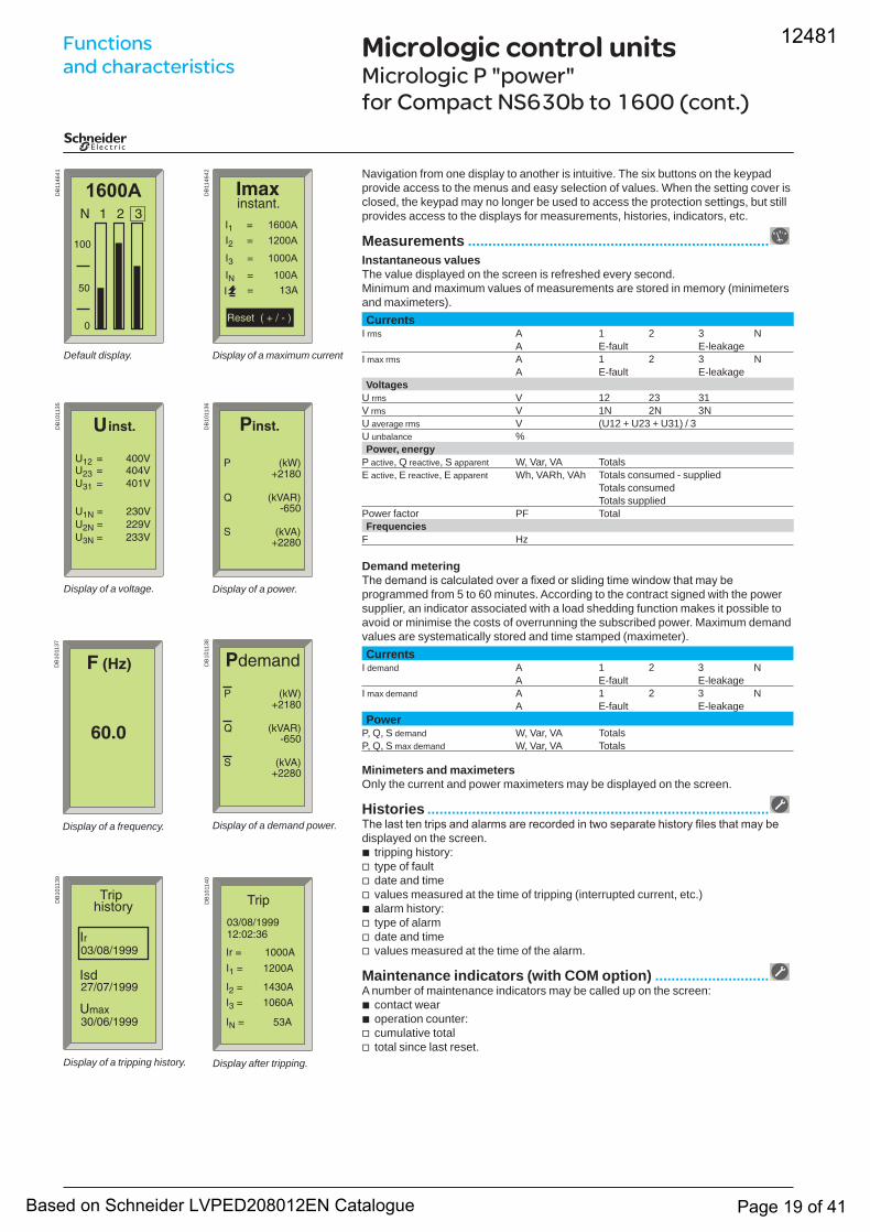
Micrologic control unitsMicrologic P "power" for Compact NS630b to 1600 (cont.)
Navigation from one display to another is intuitive. The six buttons on the keypad provide access to the menus and easy selection of values. When the setting cover is closed, the keypad may no longer be used to access the protection settings, but still provides access to the displays for measurements, histories, indicators, etc.
Measurements ..........................................................................Instantaneous valuesThe value displayed on the screen is refreshed every second. Minimum and maximum values of measurements are stored in memory (minimeters and maximeters).Currents
I rms A 1 2 3 NA E-fault E-leakage
I max rms A 1 2 3 NA E-fault E-leakage
VoltagesU rms V 12 23 31V rms V 1N 2N 3NU average rms V (U12 + U23 + U31) / 3U unbalance %Power, energy
P active, Q reactive, S apparent W, Var, VA TotalsE active, E reactive, E apparent Wh, VARh, VAh Totals consumed - supplied
Totals consumedTotals supplied
Power factor PF TotalFrequencies
F Hz
Demand meteringThe demand is calculated over a fixed or sliding time window that may be programmed from 5 to 60 minutes. According to the contract signed with the power supplier, an indicator associated with a load shedding function makes it possible to avoid or minimise the costs of overrunning the subscribed power. Maximum demand values are systematically stored and time stamped (maximeter).Currents
I demand A 1 2 3 NA E-fault E-leakage
I max demand A 1 2 3 NA E-fault E-leakage
PowerP, Q, S demand W, Var, VA TotalsP, Q, S max demand W, Var, VA Totals
Minimeters and maximetersOnly the current and power maximeters may be displayed on the screen.
Histories ....................................................................................The last ten trips and alarms are recorded in two separate history files that may be displayed on the screen.
tripping history:type of faultdate and timevalues measured at the time of tripping (interrupted current, etc.)alarm history:type of alarmdate and timevalues measured at the time of the alarm.
Maintenance indicators (with COM option) ............................A number of maintenance indicators may be called up on the screen:
contact wearoperation counter:cumulative totaltotal since last reset.
bvvvbvvv
bbvv
DB
1146
41
Default display.
DB
1146
42
Display of a maximum current
DB
1011
35
Display of a voltage.
DB
1011
36
Display of a power.
DB
1011
37
Display of a frequency.
DB
1011
40
Display after tripping.
DB
1011
38
Display of a demand power.
DB
1011
39
Display of a tripping history.
Functions and characteristics
12481
Based on Schneider LVPED208012EN Catalogue Page 19 of 41
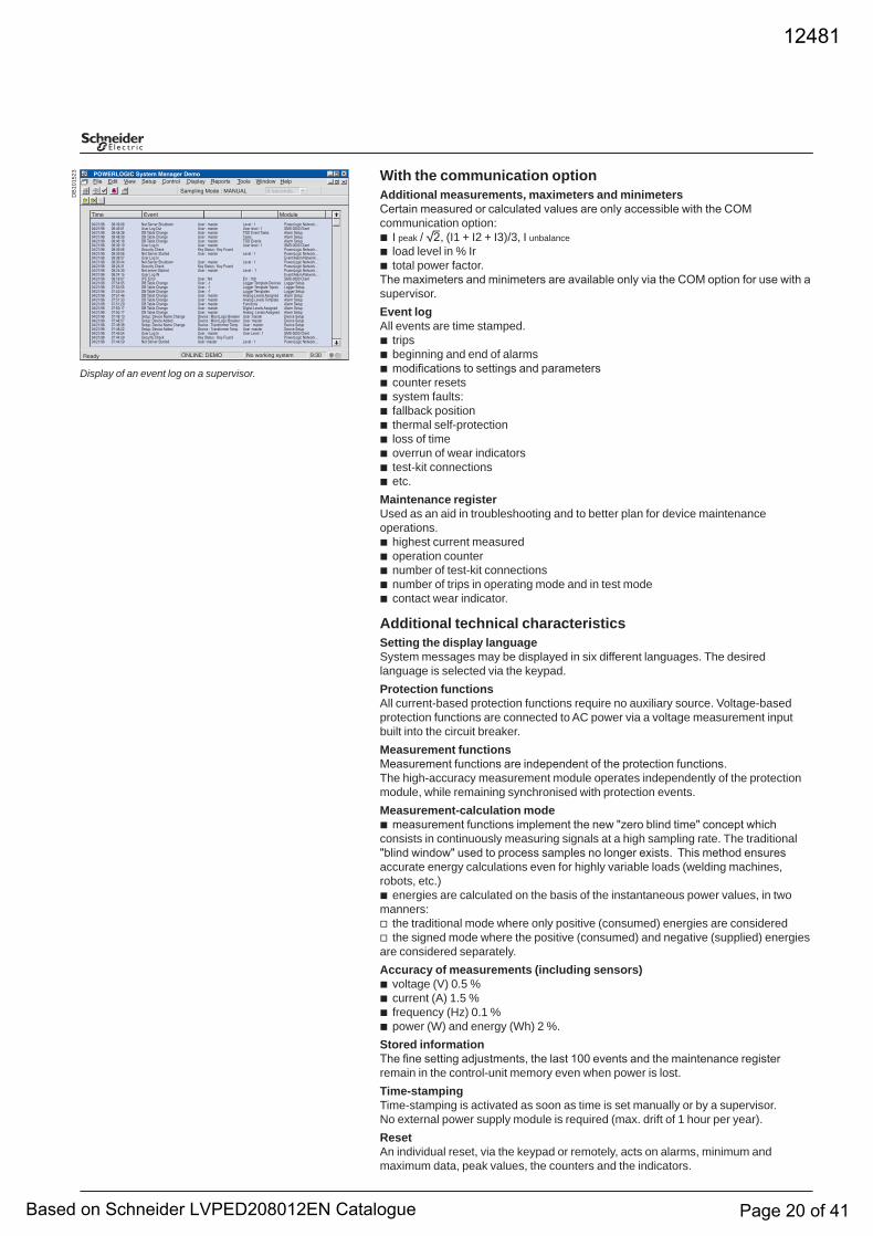
With the communication optionAdditional measurements, maximeters and minimetersCertain measured or calculated values are only accessible with the COM communication option:
I peak / 2, (I1 + I2 + I3)/3, I unbalanceload level in % Irtotal power factor.
The maximeters and minimeters are available only via the COM option for use with a supervisor.Event logAll events are time stamped.
tripsbeginning and end of alarmsmodifications to settings and parameterscounter resetssystem faults:fallback positionthermal self-protectionloss of timeoverrun of wear indicatorstest-kit connectionsetc.
Maintenance registerUsed as an aid in troubleshooting and to better plan for device maintenance operations.
highest current measuredoperation counternumber of test-kit connectionsnumber of trips in operating mode and in test modecontact wear indicator.
Additional technical characteristicsSetting the display languageSystem messages may be displayed in six different languages. The desired language is selected via the keypad.Protection functionsAll current-based protection functions require no auxiliary source. Voltage-based protection functions are connected to AC power via a voltage measurement input built into the circuit breaker.Measurement functionsMeasurement functions are independent of the protection functions.The high-accuracy measurement module operates independently of the protection module, while remaining synchronised with protection events.Measurement-calculation mode
measurement functions implement the new "zero blind time" concept which consists in continuously measuring signals at a high sampling rate. The traditional "blind window" used to process samples no longer exists. This method ensures accurate energy calculations even for highly variable loads (welding machines, robots, etc.)
energies are calculated on the basis of the instantaneous power values, in two manners:
the traditional mode where only positive (consumed) energies are consideredthe signed mode where the positive (consumed) and negative (supplied) energies
are considered separately.Accuracy of measurements (including sensors)
voltage (V) 0.5 %current (A) 1.5 %frequency (Hz) 0.1 %power (W) and energy (Wh) 2 %.
Stored informationThe fine setting adjustments, the last 100 events and the maintenance register remain in the control-unit memory even when power is lost.Time-stampingTime-stamping is activated as soon as time is set manually or by a supervisor.No external power supply module is required (max. drift of 1 hour per year).ResetAn individual reset, via the keypad or remotely, acts on alarms, minimum and maximum data, peak values, the counters and the indicators.
bbb
bbbbbbbbbbb
bbbbb
b
b
vv
bbbb
DB
1015
23
Display of an event log on a supervisor.
12481
Based on Schneider LVPED208012EN Catalogue Page 20 of 41

Tripping curvesCompact NS100 to 250 Protection of distribution systems
TM magnetic trip units
Additional characteristicsD
B11
5267
�� �� � � � � � � �� �� �� �� �� ��� ��� ���
� � � �
�� ���� ���
� ���
� ���
���
���
���
��
��
�
�
�
��
��
�����
������
����
��������
����
��
����� � �� � ��
������ �������� �� � � ���
����� � � � ��
TM25D / TM25GTM16D / TM16G
TM32D / TM40D / TM40G TM50D / TM63D / TM63G
DB
1152
69
�� �� � � � � � � �� �� �� �� �� ��� ��� ���
� � � �
�� ���� ���
� ���
� ���
���
���
���
��
��
��
�
�
�
��
��
�����
������
����
��������
����
������ �������� �� � � ���
����� � ���� � ��
����� � �� � ��
����� �� � � �
DB
1152
68
�� �� � � � � � � �� �� �� �� �� ��� ��� ���
� � ��
�� ���� ���
� ���
� ���
���
���
���
��
��
��
�
�
�
��
��
�����
������
����
��������
����
������ �������� �� � �� ��
����� � �� � ��
����� ���� � ��
DB
1152
70
�� �� � � � � � � �� �� �� �� �� ��� ��� ���
� � ��
�� ���� ���
� ���
� ���
���
���
���
��
��
��
�
�
�
��
��
�����
������
����
��������
����
������ �������� �� � �� ��
����� � � � ��
����� � �� � ��
����� �� � ��
12481
Based on Schneider LVPED208012EN Catalogue Page 21 of 41
TM magnetic trip units (cont.)
DB
1152
71
�� �� � � � � � � �� �� �� �� �� ��� ��� ���
� � � �
�� ���� ���
� ���
� ���
���
���
���
��
��
��
�
�
�
��
��
�����
������
����
��������
����
������� � � � ��
����������� � ���� � ��
� � � ��������� �������� �
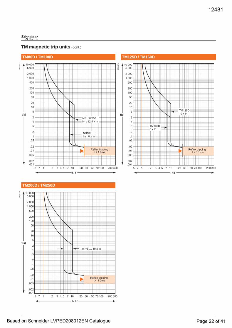
TM125D / TM160DTM80D / TM100D
TM200D / TM250D
DB
1152
73
�� �� � � � � � � �� �� �� �� �� ��� ��� ���
� � � �
�� ���� ���
� ���
� ���
���
���
���
��
��
��
�
�
�
��
��
�����
������
����
��������
����
� � �� � �� � ��
������ �������� �� � � ���
DB
1152
72
�� �� � � � � � � �� �� �� �� �� ��� ��� ���
� � ��
�� ���� ���
� ���
� ���
���
���
���
��
��
��
�
�
�
��
��
�����
������
����
��������
����
������ �������� �� � �� ��
�������� � ��
������� � ��
12481
Based on Schneider LVPED208012EN Catalogue Page 22 of 41
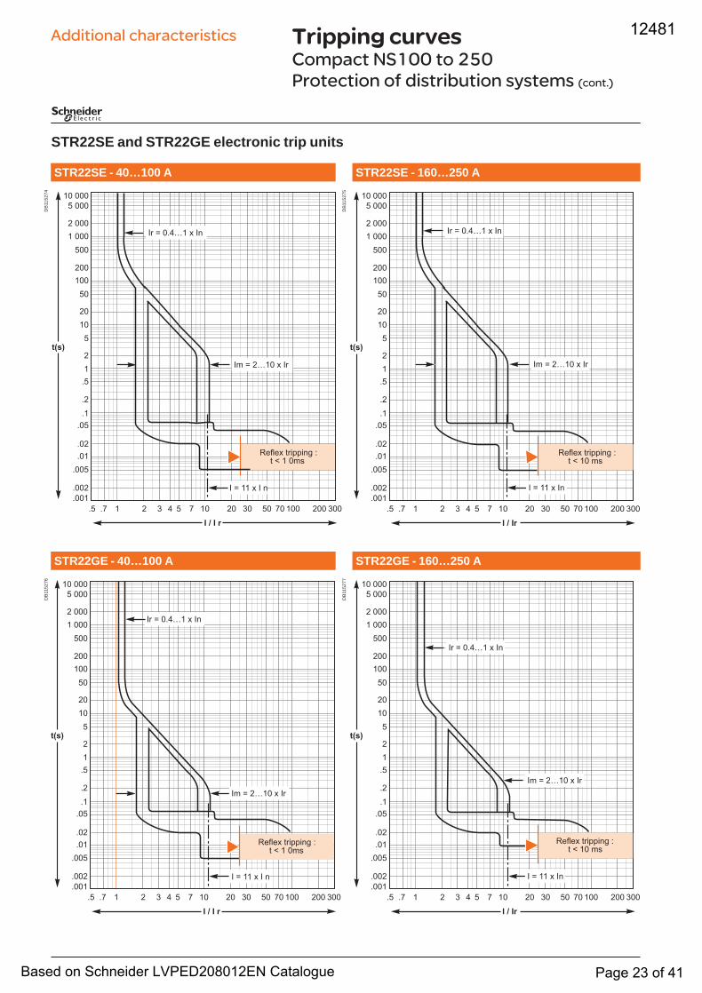
STR22SE and STR22GE electronic trip units
Tripping curvesCompact NS100 to 250 Protection of distribution systems (cont.)
Additional characteristicsD
B11
5274
�� �� � � � � � � �� �� �� �� �� ��� ��� ���
� � � �
�� ���� ���
� ���
� ���
���
���
���
��
��
��
�
�
�
��
��
�����
������
����
��������
����
�� � ���� � ��
�� � ����� � ��
� � �� � � �
������ �������� �� � � ���
STR22SE - 160…250 ASTR22SE - 40…100 A
STR22GE - 40…100 A STR22GE - 160…250 A
DB
1152
76
�� �� � � � � � � �� �� �� �� �� ��� ��� ���
� � � �
�� ���� ���
� ���
� ���
���
���
���
��
��
��
�
�
�
��
��
�����
������
����
��������
����
�� � ���� � ��
� � �� � � �
������ �������� �� � � ���
�� � ����� � ��
DB
1152
75
�� �� � � � � � � �� �� �� �� �� ��� ��� ���
� � ��
�� ���� ���
� ���
� ���
���
���
���
��
��
��
�
�
�
��
��
�����
������
����
��������
����
������ �������� �� � �� ��
�� � ���� � ��
�� � ����� � ��
� � �� � ��
DB
1152
77
�� �� � � � � � � �� �� �� �� �� ��� ��� ���
� � ��
�� ���� ���
� ���
� ���
���
���
���
��
��
��
�
�
�
��
��
�����
������
����
��������
����
�� � ����� � ��
�� � ���� � ��
� � �� � ��
������ �������� �� � �� ��
12481
Based on Schneider LVPED208012EN Catalogue Page 23 of 41
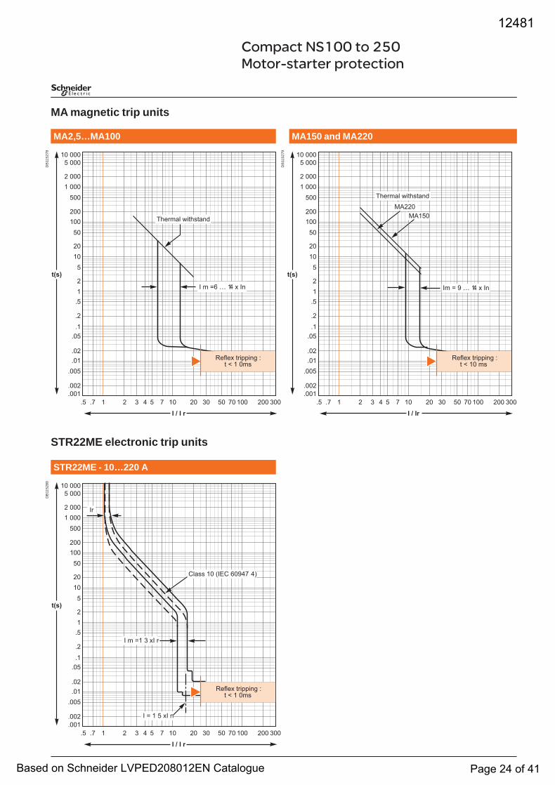
Compact NS100 to 250 Motor-starter protection
MA magnetic trip units
STR22ME electronic trip units
DB
1152
78
�� �� � � � � � � �� �� �� �� �� ��� ��� ���
� � � �
�� ���� ���
� ���
� ���
���
���
���
��
��
��
�
�
�
��
��
�����
������
����
��������
����
� � �� � �� � ��
������� ���������
������ �������� �� � � ���
MA150 and MA220MA2,5…MA100
STR22ME - 10…220 A
DB
1152
80
�� �� � � � � � � �� �� �� �� �� ��� ��� ���
� � � �
�� ���� ���
� ���
� ���
���
���
���
��
��
��
�
�
�
��
��
�����
������
����
��������
����
��
� � �� � �� �
� � � � �� �
����� �� ���� ����� ��
������ �������� �� � � ���
DB
1152
79
�� �� � � � � � � �� �� �� �� �� ��� ��� ���
� � ��
�� ���� ���
� ���
� ���
���
���
���
��
��
��
�
�
�
��
��
�����
������
����
��������
����
����������
������� ���������
�� � � � �� � ��
������ �������� �� � �� ��
12481
Based on Schneider LVPED208012EN Catalogue Page 24 of 41
Tripping curvesCompact NS400 to 630 Protection of distribution systems
Earth-fault protection
STR23 and STR53 electronic trip units
Additional characteristicsD
B11
5281
�� �� � � � � � � �� �� �� �� �� ��� ��� ���
� � � �
�� ���� ���
� ���
� ���
���
���
���
��
��
��
�
�
�
��
��
�����
������
����
��������
����
������ �������� �� � � ���
� � �� � ��
��� � ���� � ��
�� � ����� � ��
STR53UE / STR53SVSTR23SE / STR23SV
Options for STR53UE
DB
1152
83
��� ��� �� �� �� �� �� �� � � � � � �� �� ��
� � ��
�� ���� ���
� ���
� ���
���
���
���
��
��
��
�
�
�
��
��
�����
������
����
��������
����
��� ��
�� � ����� � ��
��� ���
� �
� �
� �
� �
DB
1152
82
� � �� � � ��
�� �� � � � � � � �� �� � � �� �� �� ��
�� ���� ���
� ���
� ���
���
���
���
��
��
��
�
�
�
��
��
�����
������
����
��������
����
�� � ������ �
��� � ������ � ��
����
�
������
�� � ����� � ��
� � ���
�� � ������ � ��
������ �������� �� � � ���
�� � ���
12481
Based on Schneider LVPED208012EN Catalogue Page 25 of 41
Compact NS400 to 630 Motor-starter protection
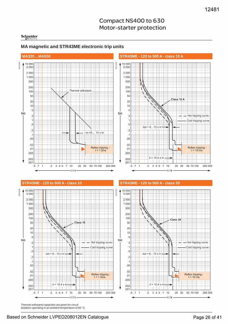
MA magnetic and STR43ME electronic trip units
Thermal-withstand capacities are given for circuit breakers operating in an ambient temperature of 65 °C.
DB
1152
84
�� �� � � � � � � �� �� �� �� �� ��� ��� ���
� � � �
�� ���� ���
� ���
� ���
���
���
���
��
��
��
�
�
�
��
��
�����
������
����
��������
����
� � �� ��� �� � ��
������� ���������
������ �������� �� � � ���
STR43ME - 120 to 500 A - class 10 AMA320…MA500
STR43ME - 120 to 500 A - class 10 STR43ME - 120 to 500 A - class 20
DB
1152
86
�� �� � � � � � � �� �� �� �� �� ��� ��� ���
� � � �
�� ���� ���
� ���
� ���
���
���
���
��
��
��
�
�
�
��
��
�����
������
����
��������
����
����� ��
��� �������� �����
���� �������� �����
�� � ���� � ��
��� � ���� � ��
������ �������� �� � � ���
DB
1152
85
�� �� � � � � � � �� �� �� �� �� ��� ��� ���
� � ��
�� ���� ���
� ���
� ���
���
���
���
��
��
��
�
�
�
��
��
�����
������
����
��������
������� �������� �����
���� �������� �����
����� �� �
�� � ���� � ��
��� � ���� � ��
������ �������� �� � �� ��
DB
1152
87
�� �� � � � � � � �� �� �� �� �� ��� ��� ���
� � ��
�� ���� ���
� ���
� ���
���
���
���
��
��
��
�
�
�
��
��
�����
������
����
��������
������� �������� �����
���� �������� �����
�� � ���� � ��
��� � ���� � ��
����� ��
������ �������� �� � �� ��
12481
Based on Schneider LVPED208012EN Catalogue Page 26 of 41
Tripping curvesCompact NS630b to 3200
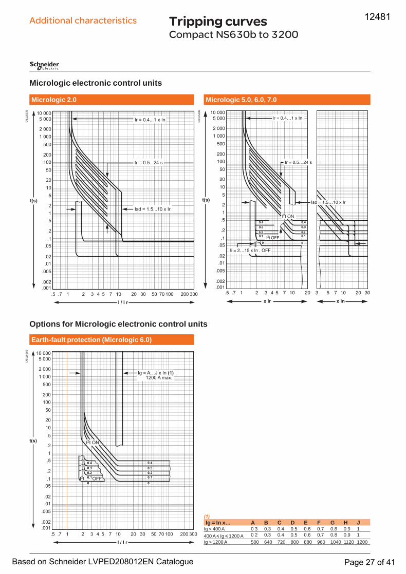
Micrologic electronic control units
Options for Micrologic electronic control units
(1)Ig = In x… A B C D E F G H J
Ig < 400 A 0 3 0.3 0.4 0.5 0.6 0.7 0.8 0.9 1400 A y Ig y 1200 A 0 2 0.3 0.4 0.5 0.6 0.7 0.8 0.9 1Ig > 1200 A 500 640 720 800 880 960 1040 1120 1200
Additional characteristicsD
B11
5239
�� �� � � � � � � �� �� �� �� �� ��� ��� ���
� � � �
�� ���� ���
� ���
� ���
���
���
���
��
��
��
�
�
�
��
��
�����
������
����
��������
����
��� � �������� � ��
�� � �������� �
�� � ������� � ��
Micrologic 5.0, 6.0, 7.0Micrologic 2.0
Earth-fault protection (Micrologic 6.0)
DB
1152
89
�� �� � � � � � � �� �� �� �� �� ��� ��� ���
� � � �
�� ���� ���
� ���
� ���
���
���
���
��
��
��
�
�
�
��
��
�����
������
����
��������
����
�� � ��� � �� ������� � ����
��� ���
���
���������
��� ��
���
���������
� �
DB
1152
88
12481
Based on Schneider LVPED208012EN Catalogue Page 27 of 41
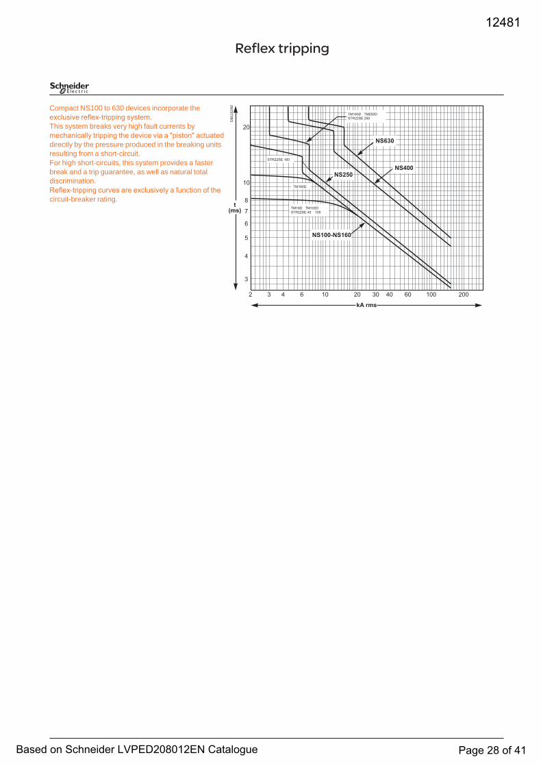
Reflex tripping
Compact NS100 to 630 devices incorporate the exclusive reflex-tripping system.This system breaks very high fault currents by mechanically tripping the device via a "piston" actuated directly by the pressure produced in the breaking units resulting from a short-circuit.For high short-circuits, this system provides a faster break and a trip guarantee, as well as natural total discrimination.Reflex-tripping curves are exclusively a function of the circuit-breaker rating.
�
��
��
�
�
�
�
�
� � � � �� �� �� �� �� ��� ���
����� ����� ������
������� �� ���
������� ���
������
�����
����������
�����������
������ ������������� ���
�� ���
DB
1152
90
12481
Based on Schneider LVPED208012EN Catalogue Page 28 of 41
Dimensionsand connection
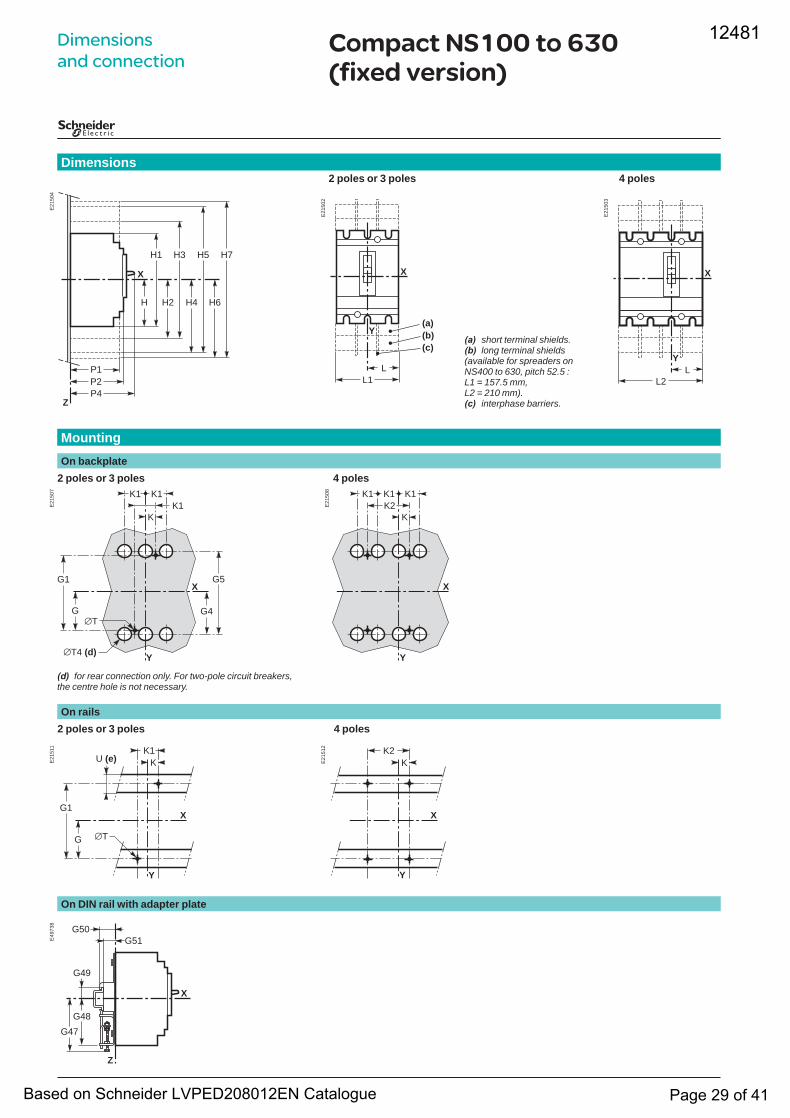
Compact NS100 to 630 (fixed version)
(d) for rear connection only. For two-pole circuit breakers, the centre hole is not necessary.
(a) short terminal shields.(b) long terminal shields(available for spreaders onNS400 to 630, pitch 52.5 : L1 = 157.5 mm, L2 = 210 mm).(c) interphase barriers.
2 poles or 3 poles 4 polesDimensions
Mounting
2 poles or 3 poles 4 polesOn backplate
2 poles or 3 poles 4 polesOn rails
On DIN rail with adapter plate
E21
504
H
Z
H1
H2
H3 H5 H7
H4 H6
P1P2P4
X
E21
502
X
Y
L1L
(a)(b)(c)
E21
503
X
Y
L2L
E21
507
K
G
G1
K1 K1K1
G4
G5X
Y
∅T
∅T4 (d)
E21
508
K
K1 K1 K1
X
Y
K2
E21
511
Y
X
K1
G
G1
∅T
U (e) K E21
512
Y
X
K2K
E49
738
Z
X
G48G47
G49
G51G50
12481
Based on Schneider LVPED208012EN Catalogue Page 29 of 41
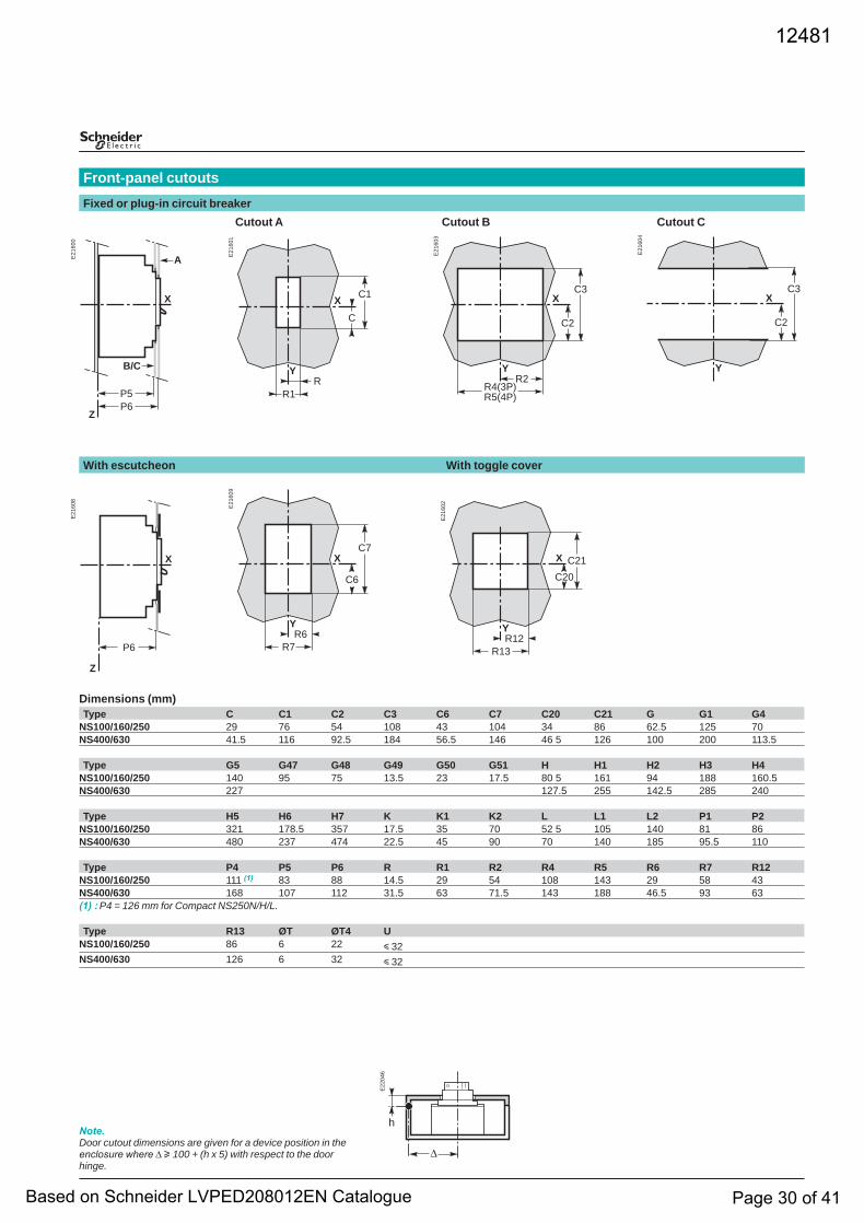
Dimensions (mm)Type C C1 C2 C3 C6 C7 C20 C21 G G1 G4
NS100/160/250 29 76 54 108 43 104 34 86 62.5 125 70NS400/630 41.5 116 92.5 184 56.5 146 46 5 126 100 200 113.5
Type G5 G47 G48 G49 G50 G51 H H1 H2 H3 H4NS100/160/250 140 95 75 13.5 23 17.5 80 5 161 94 188 160.5NS400/630 227 127.5 255 142.5 285 240
Type H5 H6 H7 K K1 K2 L L1 L2 P1 P2NS100/160/250 321 178.5 357 17.5 35 70 52 5 105 140 81 86NS400/630 480 237 474 22.5 45 90 70 140 185 95.5 110
Type P4 P5 P6 R R1 R2 R4 R5 R6 R7 R12NS100/160/250 111 (1) 83 88 14.5 29 54 108 143 29 58 43NS400/630 168 107 112 31.5 63 71.5 143 188 46.5 93 63(1) : P4 = 126 mm for Compact NS250N/H/L.
Type R13 ØT ØT4 UNS100/160/250 86 6 22 y 32NS400/630 126 6 32 y 32
Note.Door cutout dimensions are given for a device position in the enclosure where ∆ u 100 + (h x 5) with respect to the door hinge.
Cutout A Cutout B Cutout C
Front-panel cutouts Fixed or plug-in circuit breaker
With escutcheon With toggle cover
E21
600
X
P5P6
A
B/C
Z
E21
601
X
Y
C
C1
RR1
E21
603
X
Y
C2
C3
R2R4(3P)R5(4P)
E21
604
X
Y
C2
C3
E21
608
X
P6
Z
E21
609
X
Y
C6
C7
R6R7
E21
602
C20C21X
R13R12Y
E22
046
∆
h
12481
Based on Schneider LVPED208012EN Catalogue Page 30 of 41
E21
534
Y
X
K20K22
E21
525 K
G10
G11
K1
G12
G13
K5K6
X
Y∅T
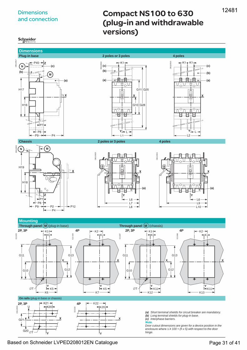
Dimensionsand connection
(a) Short terminal shields for circuit breaker are mandatory. (b) Long terminal shields for plug-in base. (c) Interphase barriers. Note.Door cutout dimensions are given for a device position in the enclosure where ∆ u 100 + (h x 5) with respect to the door hinge.
Compact NS100 to 630 (plug-in and withdrawable versions)
DimensionsPlug-in base 2 poles or 3 poles 4 poles
DB
1109
17
DB
1109
18
DB
1109
19
Chassis 2 poles or 3 poles 4 poles
DB
1109
32
DB
1109
20
DB
1109
21
E21
526 K
K2
K5K7
X
Y
DB
1109
33
2P, 3P 4POn rails (plug-in base or chassis)
E21
587 K
G10
G11
K1
G12
G13
K11K12
X
Y∅T
Mounting
2P, 3P 4P 2P, 3P 4PThrough panel M (plug-in base) Through panel M (chassis)
E21
588 K
K2
K11K13
X
Y
12481
Based on Schneider LVPED208012EN Catalogue Page 31 of 41
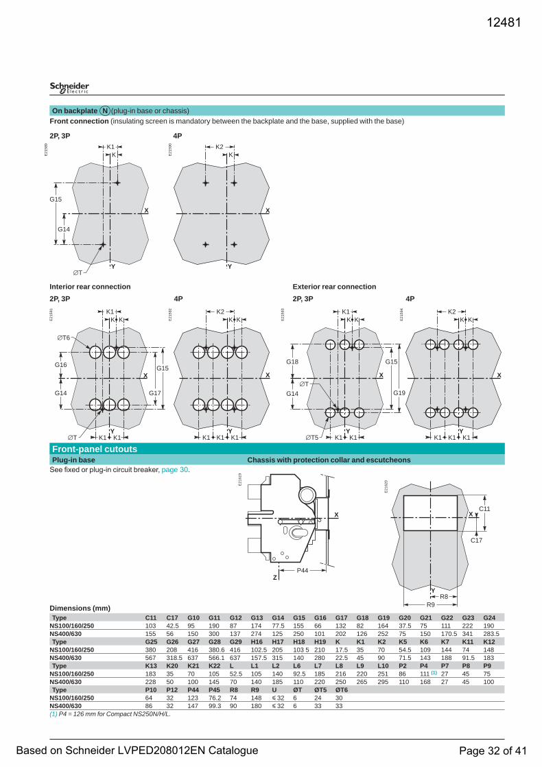
On backplate N (plug-in base or chassis)Front connection (insulating screen is mandatory between the backplate and the base, supplied with the base)
2P, 3P 4P
Dimensions (mm)Type C11 C17 G10 G11 G12 G13 G14 G15 G16 G17 G18 G19 G20 G21 G22 G23 G24
NS100/160/250 103 42.5 95 190 87 174 77.5 155 66 132 82 164 37.5 75 111 222 190NS400/630 155 56 150 300 137 274 125 250 101 202 126 252 75 150 170.5 341 283.5Type G25 G26 G27 G28 G29 H16 H17 H18 H19 K K1 K2 K5 K6 K7 K11 K12
NS100/160/250 380 208 416 380.6 416 102.5 205 103 5 210 17.5 35 70 54.5 109 144 74 148NS400/630 567 318.5 637 566.1 637 157.5 315 140 280 22.5 45 90 71.5 143 188 91.5 183Type K13 K20 K21 K22 L L1 L2 L6 L7 L8 L9 L10 P2 P4 P7 P8 P9
NS100/160/250 183 35 70 105 52.5 105 140 92.5 185 216 220 251 86 111 (1) 27 45 75NS400/630 228 50 100 145 70 140 185 110 220 250 265 295 110 168 27 45 100Type P10 P12 P44 P45 R8 R9 U ØT ØT5 ØT6
NS100/160/250 64 32 123 76.2 74 148 y 32 6 24 30NS400/630 86 32 147 99.3 90 180 y 32 6 33 33(1) P4 = 126 mm for Compact NS250N/H/L.
E21
589
K
G14
G15
K1
X
Y∅T
E21
590
KK2
X
Y
E21
591
K
G14
G15
K1
G17
K1
X
Y∅T
K
K1
G16
∅T6
E21
592 K2
X
YK1K1 K1
K K E21
593
G14
G15
K1
X
Y
∅T
K K
K1K1
G18
G19
∅T5
E21
594 K2
X
Y
K K
K1K1 K1
E21
619
P44
X
Z
E21
620
Y
C17
C11
R8R9
X
Interior rear connection Exterior rear connection2P, 3P 4P 2P, 3P 4P
See fixed or plug-in circuit breaker, page 30.
Front-panel cutouts Plug-in base Chassis with protection collar and escutcheons
12481
Based on Schneider LVPED208012EN Catalogue Page 32 of 41
Dimensionsand connection
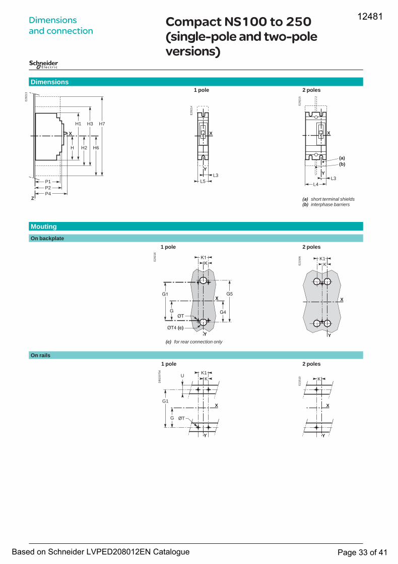
Compact NS100 to 250 (single-pole and two-pole versions)
(a) short terminal shields(b) interphase barriers
(c) for rear connection only
1 pole 2 polesDimensions
1 pole 2 poles
MoutingOn backplate
1 pole 2 polesOn rails
E29
213
H
Z
H1
H2
H3 H7
H6
P1P2P4
X
E29
214
X
Y
L5L3
E29
215
X
Y
L4L3
(a)(b)
E29
216
���
�
�
���
��
��
��
��� ���
E21
506 K1
X
Y
K
DB
1037
54
Y
X
K1K
U
ØTG
G1
E21
510
Y
X
K
12481
Based on Schneider LVPED208012EN Catalogue Page 33 of 41
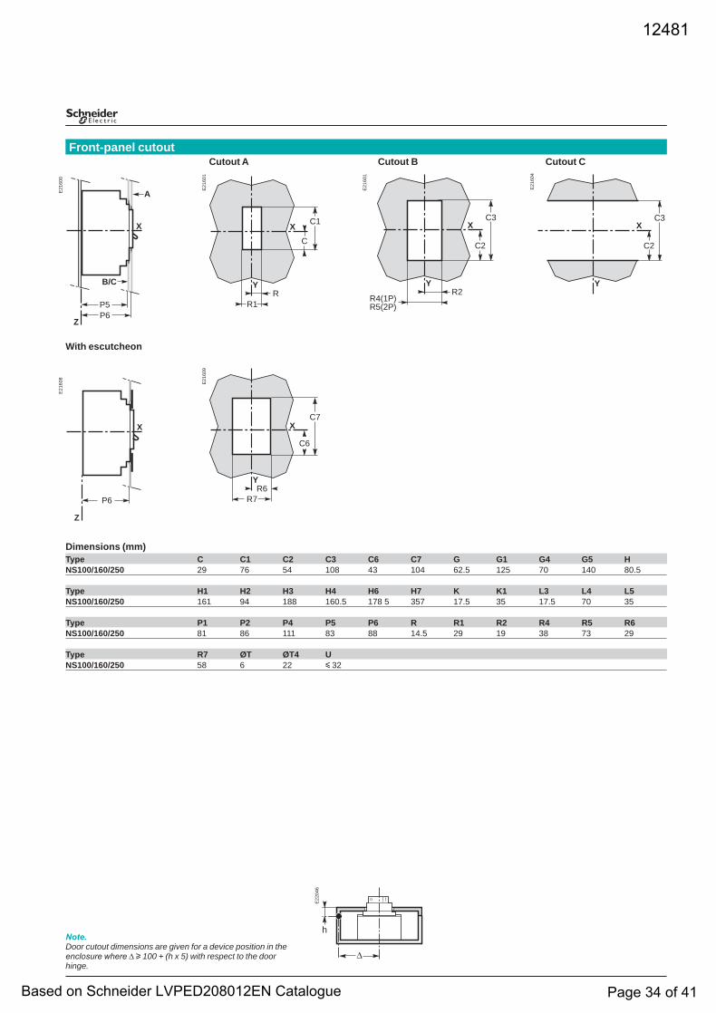
With escutcheon
Dimensions (mm)Type C C1 C2 C3 C6 C7 G G1 G4 G5 HNS100/160/250 29 76 54 108 43 104 62.5 125 70 140 80.5
Type H1 H2 H3 H4 H6 H7 K K1 L3 L4 L5NS100/160/250 161 94 188 160.5 178 5 357 17.5 35 17.5 70 35
Type P1 P2 P4 P5 P6 R R1 R2 R4 R5 R6NS100/160/250 81 86 111 83 88 14.5 29 19 38 73 29
Type R7 ØT ØT4 UNS100/160/250 58 6 22 y 32
Note.Door cutout dimensions are given for a device position in the enclosure where ∆ u 100 + (h x 5) with respect to the door hinge.
Cutout A Cutout B Cutout CFront-panel cutout
E21
600
X
P5P6
A
B/C
Z
E21
601
X
Y
C
C1
RR1
E21
601
X
Y
C2
C3
R2R4(1P)R5(2P)
E21
604
X
Y
C2
C3
E21
608
X
P6
Z
E21
609
X
Y
C6
C7
R6R7
E22
046
∆
h
12481
Based on Schneider LVPED208012EN Catalogue Page 34 of 41
X
105
94
105
Y
105 (3P)175 (4P)
188
123
99,599,5 (3P)169,5 (4P)
3570
117
234
100
200
123
210X
105
94
105
Y
105 (3P)175 (4P)
188
123
3570
117
234
123
99,5
200
99,5 (3P)169,5 (4P)
100
X
Y
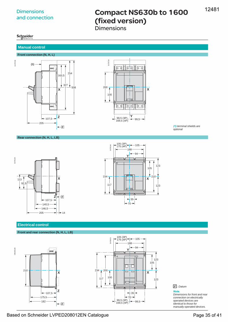
Compact NS630b to 1600 (fixed version)Dimensions
Electrical control
Front and rear connection (N, H, L, LB)
E47
897A
Rear connection (N, H, L, LB)
E47
914A
Manual control
Front connection (N, H, L)
E47
973A
Note.Dimensions for front and rear connection on electrically operated devices are identical to those for manually operated devices.
F : Datum
(1) terminal shields are optional
Dimensions and connection
E47
972B
X
F
Z
254
508
107,5
205
163,5
327
(1)
E47
913A
X
F
205 14
92,5113
107,5140,5
146,5
Z
DB
1051
38
X
F
Z
210
182175,5
107,5
12481
Based on Schneider LVPED208012EN Catalogue Page 35 of 41
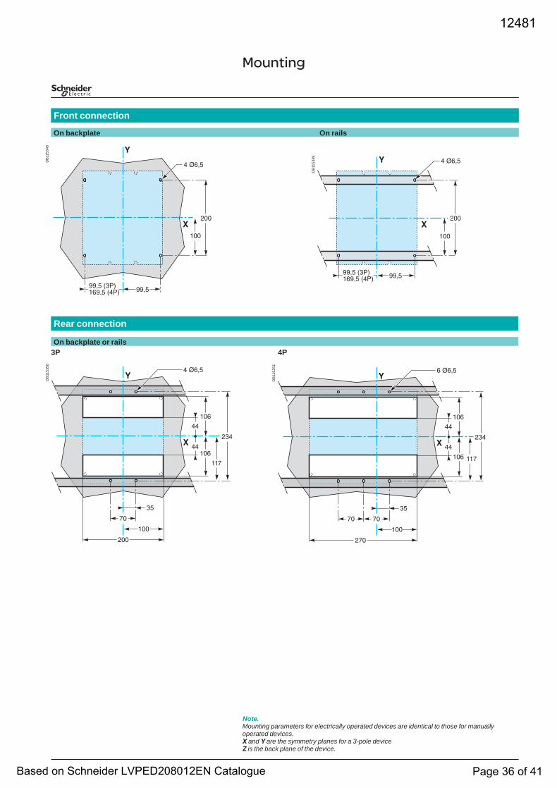
Front connection
On backplate On rails
Rear connection
On backplate or rails3P 4P
Note.Mounting parameters for electrically operated devices are identical to those for manually operated devices.X and Y are the symmetry planes for a 3-pole deviceZ is the back plane of the device.
MountingD
B11
5348
����
���
�������� ��������� ����
�
� ����
DB
1153
49
����
���
� �����
�������� ��������� ����
DB
1153
50
�
�� ����
���
���
��
�����
���
��
��
���
���
DB
1153
51
�
�� ����
���
���
��
��
���
��
��
���
���
��
���
12481
Based on Schneider LVPED208012EN Catalogue Page 36 of 41
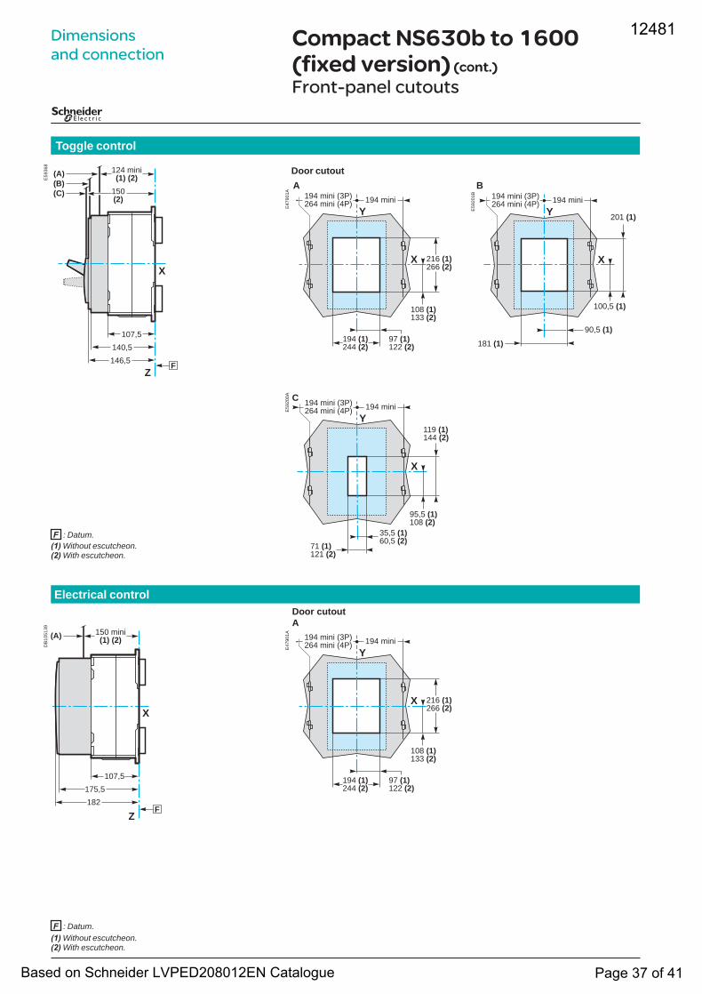
Electrical controlDoor cutout A
Toggle control
Door cutout A B
(1) Without escutcheon.(2) With escutcheon.
(1) Without escutcheon.(2) With escutcheon.
Compact NS630b to 1600 (fixed version) (cont.)
Front-panel cutouts
F : Datum.
F : Datum.
Dimensions and connection
E59
368
X
(C)(B)(A)
150(2)
FZ
124 mini(1) (2)
107,5140,5146,5
E47
901A
Y
X 216 (1)266 (2)
194 mini (3P)264 mini (4P) 194 mini
108 (1)133 (2)
97 (1)122 (2)
194 (1)244 (2)
E59
201B
Y
X
194 mini (3P)264 mini (4P) 194 mini
100,5 (1)
201 (1)
90,5 (1)
181 (1)
E59
200A C
Y
X
119 (1)144 (2)
194 mini (3P)264 mini (4P) 194 mini
95,5 (1)108 (2)
35,5 (1)60,5 (2)71 (1)
121 (2)
DB
1051
39
X
(A)
FZ
150 mini(1) (2)
107,5175,5182
E47
901A
Y
X 216 (1)266 (2)
194 mini (3P)264 mini (4P) 194 mini
108 (1)133 (2)
97 (1)122 (2)
194 (1)244 (2)
12481
Based on Schneider LVPED208012EN Catalogue Page 37 of 41
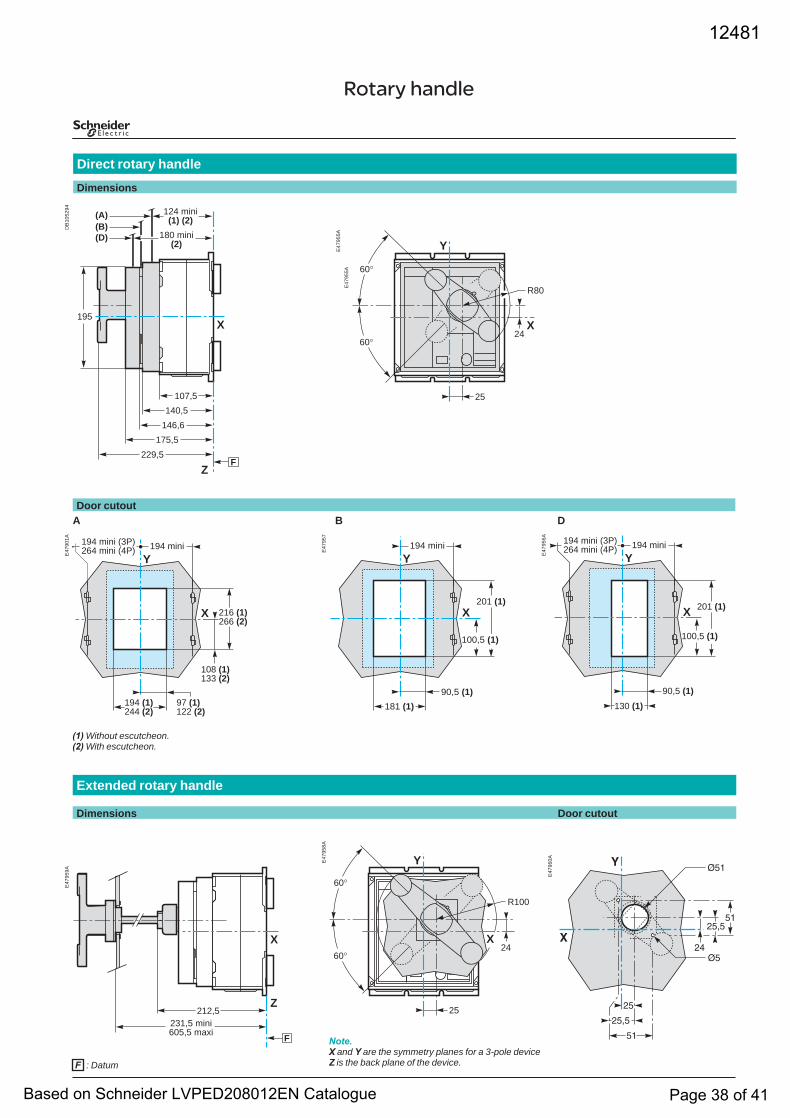
Extended rotary handle
Dimensions Door cutout
Rotary handle
Direct rotary handleDimensions
Door cutoutA B D
F : Datum
DB
1052
94
(D)(B)(A)
X
FZ
229,5
195
180 mini(2)
124 mini(1) (2)
107,5140,5
146,6175,5
E47
955A
R80
60°
60°
X
Y
25
24A55974
E
E47
901A
Y
X 216 (1)266 (2)
194 mini (3P)264 mini (4P) 194 mini
108 (1)133 (2)
97 (1)122 (2)
194 (1)244 (2)
(1) Without escutcheon.(2) With escutcheon.
E47
957
Y
X201 (1)
194 mini
90,5 (1)181 (1)
100,5 (1)
E47
956A
Y
X 201 (1)
194 mini (3P)264 mini (4P) 194 mini
90,5 (1)130 (1)
100,5 (1)
E47
959A
X
F
Z231,5 mini605,5 maxi
212,5
E47
958A
R100
60°
60°
Y
25
24X
Note.X and Y are the symmetry planes for a 3-pole deviceZ is the back plane of the device.
E47
960A �
���
��
���
��
������
����
��
12481
Based on Schneider LVPED208012EN Catalogue Page 38 of 41
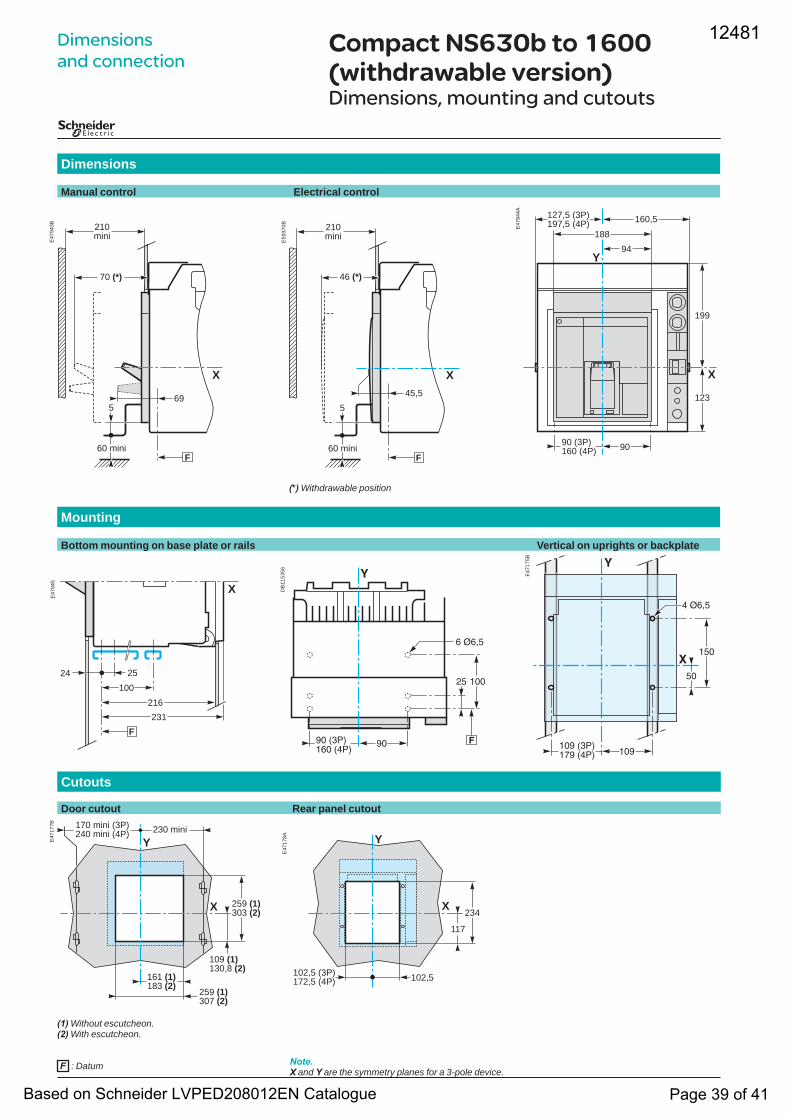
Compact NS630b to 1600 (withdrawable version)Dimensions, mounting and cutouts
Dimensions
Manual control Electrical control
Mounting
Bottom mounting on base plate or rails Vertical on uprights or backplate
Cutouts
Door cutout Rear panel cutout
F : Datum
Dimensions and connection
E47
943B 210
mini
70 (*)
60 mini
5
X
69
F
E59
370B 210
mini
46 (*)
60 mini
5
X45,5
F
(*) Withdrawable position
E47
944A
90
Y94
188160,5127,5 (3P)
197,5 (4P)
123
199
X
90 (3P)160 (4P)
E47
945
X
F
25100
24
231216
DB
1153
56 �
���� ������� ����
� ����
�
�� ���
E47
175B
� ����
�
������ ������� ����
���
��
�
E47
177B
259 (1)303 (2)
170 mini (3P)240 mini (4P) 230 mini
Y
X
109 (1)130,8 (2)
161 (1)183 (2)
259 (1)307 (2)
(1) Without escutcheon.(2) With escutcheon.
E47
178A Y
117
234X
102,5102,5 (3P)172,5 (4P)
Note.X and Y are the symmetry planes for a 3-pole device.
12481
Based on Schneider LVPED208012EN Catalogue Page 39 of 41
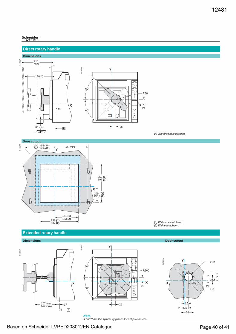
(1) Without escutcheon.(2) With escutcheon.
Door cutout
(*) Withdrawable position.
Direct rotary handleDimensions
Extended rotary handle
Dimensions Door cutout
E47
962A
136 (*)
210mini
93
60 mini
5
X
F
E47
963A
R80
Y
X
25
60°
2460°
E47
964B
161 (1)183 (2)259 (1)
307 (2)
Y
259 (1)303 (2)
X
170 mini (3P)240 mini (4P) 230 mini
109 (1)130,8 (2)
E47
965A
207 mini447 maxi
F
17
X
E47
966A
R20060°
60°
Y
25
24X
Note.X and Y are the symmetry planes for a 3-pole device.
E47
967A �
���
��
���
��
������
����
��
12481
Based on Schneider LVPED208012EN Catalogue Page 40 of 41
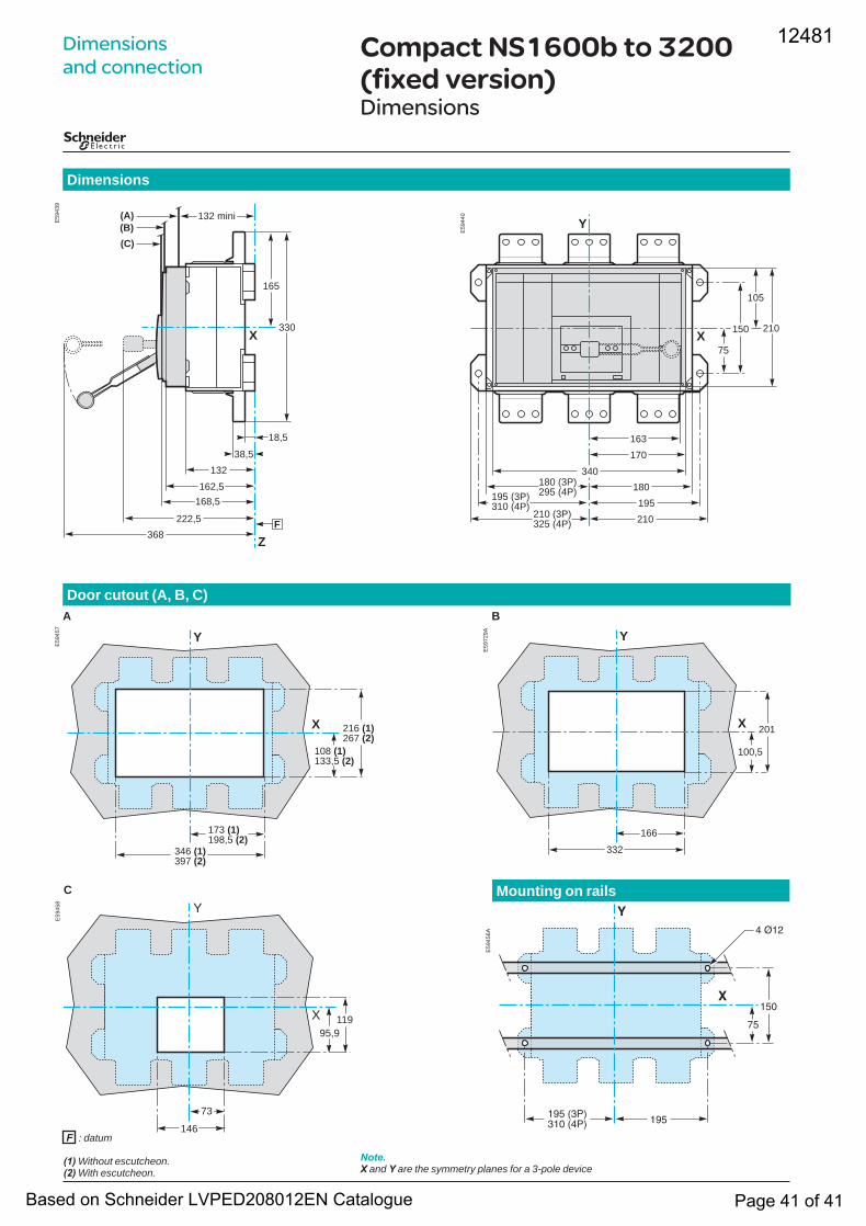
Compact NS1600b to 3200 (fixed version)Dimensions
Dimensions
�
�
��
���
� ���
������ ������� ����
E59
456A
Note.X and Y are the symmetry planes for a 3-pole device
C Mounting on rails
Dimensions and connection
E59
439
X
165
330
Z
132
368
162,5168,5
F
18,5
222,5
(C)(B)(A) 132 mini
38,5E
5944
0
210X
105
Y
75
150
170340
180180 (3P)295 (4P)
210210 (3P)325 (4P)
195195 (3P)310 (4P)
163
Door cutout (A, B, C)A B
E59
457
X
Y
346 (1)397 (2)
216 (1)267 (2)
108 (1)133,5 (2)
173 (1)198,5 (2)
E59
729A
X
Y
332
201
100,5
166
E59
458
X
Y
119
146
73
95,9
F : datum
(1) Without escutcheon.(2) With escutcheon.
12481
Based on Schneider LVPED208012EN Catalogue Page 41 of 41