schraubenspindelpumpe screw pump l3ng
TRANSCRIPT
L3N
G
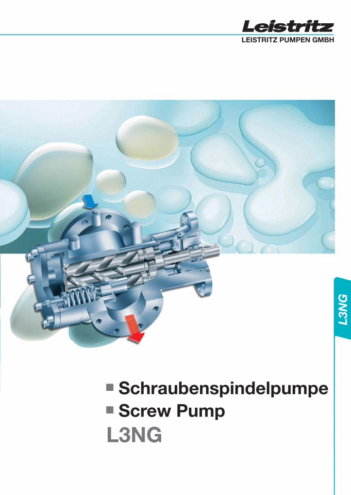
SchraubenspindelpumpeScrew Pump
L3NG

Bauform Design 20-225 3
Pulsation, Geräusch Pulsation, Noise level 20-225 3
Funktion und Wirkungsweise Function and Operation 20-225 4
Einsatzgrenzen Application limits 20-225 4
Lagerung Bearing 20-225 5
Wellenabdichtung Shaft Seal 20-225 5
Anschlüsse / Flanschanordnung Connection / Flange arrangement 20-225 5
Druckbegrenzungsventil Pressure relief valve 20-225 6
Wellenkupplung / Berührungsschutz Shaft coupling / Coupling guard 20-225 6
Antrieb Driver 20-225 6
Einbau Mounting 20-225 6
Werkstoffe Material of construction 20-225 6
Bauformen Design Code 20-225 7
Axialgeschwindigkeit Axial Flow Velocity 20-225 8
Wirkungsgrad NPSH Efficiency - NPSH 20-225 8
Leistungsdaten Performance Calculations 20-225 9
Schnittzeichnung Sectional Drawing 20-70 10
Massblatt Pump Dimensions 20-70 11
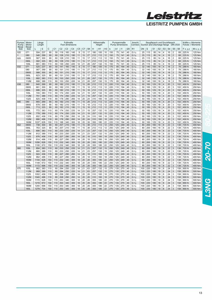
Einbauzeichnung Fusslaterne Installation Drawing / Foot Bracket 20-70 12-13
Förderstrom / Leistungstabelle 50Hz Flow and Power Data Tables 50Hz 20-70 14
Förderstrom / Leistungstabelle 60Hz Flow and Power Data Tables 60Hz 20-70 15
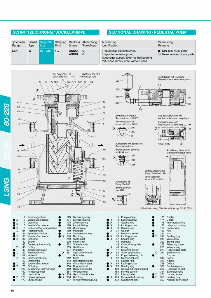
Schnittzeichnung / Sockelpumpe Sectional Drawing / Pedestal Pump 80-225 16
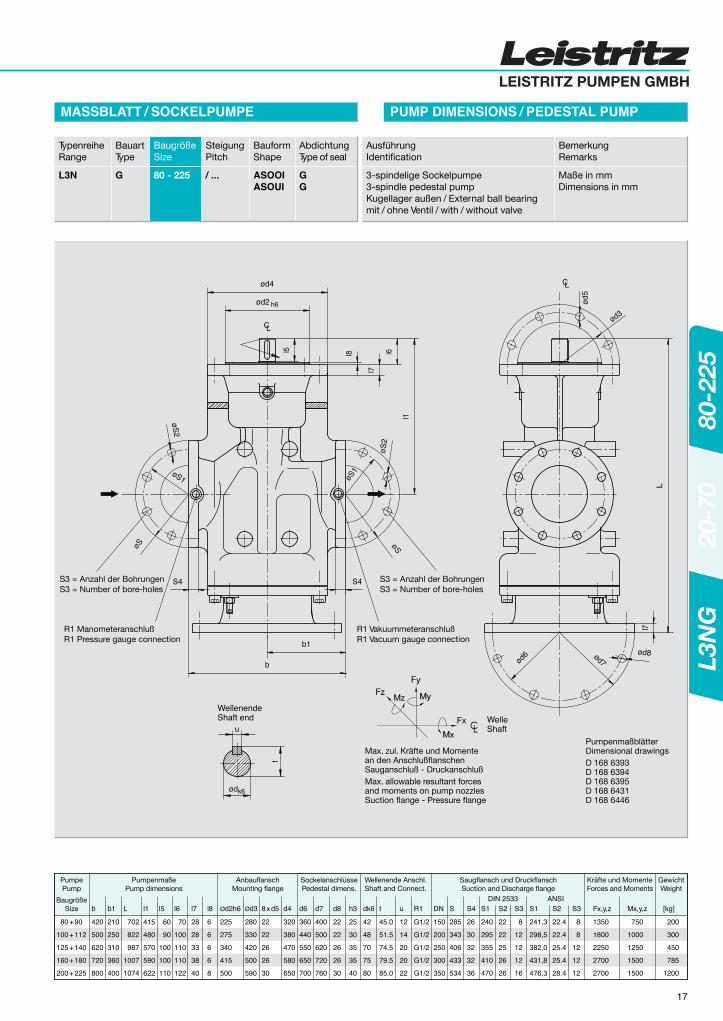
Massblatt / Sockelpumpe Pump Dimesions / Pedestal Pump 80-225 17
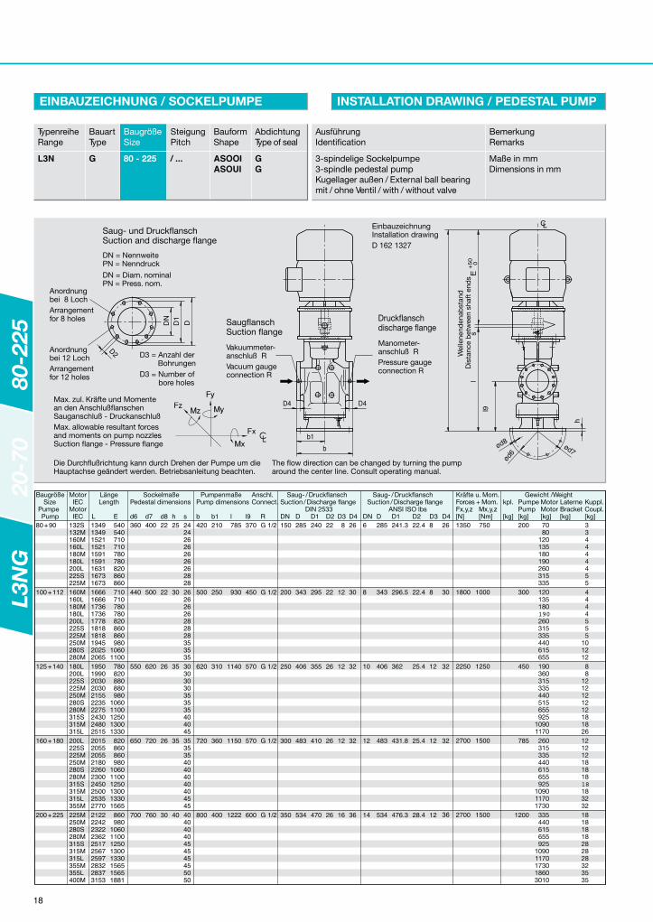
Einbauzeichnung / Sockelpumpe Installation Drawing / Pedestal Pump 80-225 18
Schnittzeichnung / Flanschpumpe Sectional Drawing / Flange Pump 80-225 19
Massblatt / Flanschpumpe Pump Dimension / Flange Pump 80-225 20
Einbauzeichnung / Fusslaterne Installation Drawing / Foot Bracket 80-225 21
Förderstrom / Leistungstabelle 50Hz Flow and Power Data Tables 50Hz 80-225 22
Förderstrom / Leistungstabelle 60Hz Flow and Power Data Tables 60Hz 80-225 23
Einsatzgebiete Application 20-225 3
Verwendung General 20-225 3
L3N
G20
-70
80-2
25
SchraubenspindelpumpeScrew PumpL3NG
2
Baugrößen/Pump Size
Seite/Page
LEISTRITZ PUMPEN GMBH
Die Leistritz Schraubenspindelpumpen der BaureiheL3NG sind selbstansaugende Verdrängerpumpen fürden Niederdruckbereich bis 16 bar und dienen zurFörderung von schmierenden Flüssigkeiten, ohneabrasive Bestandteile.
Energietechnik und Ölfeuerungsanlagen:Als Brennerbetriebspumpen, Transferpumpen, Ver- undEntsorgungspumpen, zum Fördern von schweren undleichten Heizölen, sowie für alle schmierenden Flüssig-keiten, Alt- und Restölen sowie Fetten.
Allgemeiner Maschinen- und Schwermaschinenbau:Als Schmier-, Dicht-, Regel-, Hydraulik-, Kühl- undKälteölpumpen, Be- und Entladepumpen, sowie Brenn-stoffpumpen, für Dieselmotoren, Verdichter, Gas-, Dampf- und Wasserturbinen, Getriebe, Kälteaggregate.
Schiffs- und Offshoretechnik:Als Schmier-, Regel-, Hydraulik-, Kühl-, Rohölpumpen,sowie Brennstoffpumpen, für Dieselmotoren, Verdichter,Gas-, Dampf-und Wasserturbinen, Getriebe, Kraft /Wärmeaggregate, Be- und Entladepumpen.
Chemische und petrochemische Industrie:Als Pipelinepumpe zur Förderung aller schmierendenFlüssigkeiten, wie z.B. Schmieröl-, Rohöl-, Bitumen-,Fett-, Harz-, Leim-, Glyzerinprodukte.
Selbstansaugende, Schraubenspindelpumpe, deren3 Spindeln in einem Pumpengehäuse montiert sind.Die Spindelgeometrie ist so gewählt, dass kein Schubauf das Wälzlager, welches die Antriebsspindel axialfixiert, ausgeübt wird. Abhängig vom Betriebsdruckstellt sich zwischen dem Ausgleichskolben der Antriebs-spindel und dem Spindelkopf der Laufspindel ein ent-sprechender Drosselspalt ein, der die hydrodynamischeLagerung der Spindeln und die Schmierung bzw. Küh-lung der Gleitringdichtung gewährleistet.Der Antrieb der Laufspindel erfolgt hydraulisch, überdie Spindelflanken wird lediglich das aus der Flüssig-keitsreibung resultierende Drehmoment übertragen.Die Spindeln laufen daher praktisch belastungsfrei undunterliegen somit keinem Verschleiß.
The series L3NG of Leistritz Screw Pump is a self-priming positive displacement pump for a pressurerange up to 16 bar, suitable for transporting non-abrasive lubricating fluids.
Engines and fuel oil systems:Feed- and booster pumps, transfer pumps, supply andwaste oil pumps, for transporting heavy and light oils,for all fluids with lubricity such as lube oil, fuel oil, wasteoil and residual oil.
Rotating machinery:As lube oil-, booster, seal oil-, control-, hydraulic-,cooling- and circulating pumps, for diesel engines,compressors, gas-, steam- and water turbines, gears,refrigerating machinery.
Shipbuilding- and offshore industry:As lube oil-, transfer-, hydraulic-, cooling- and circu-ating oil pumps and fuel pumps for diesel engines,compressors, gas-, steam- turbines and gears, cargoand unloading pumps.
Chemical and Petrochemical industry:As transfer pump for all lubricating fluids, e.g. lube oil,crude oil-, tar-, grease-, resin-, adhesive- and gly-cerinproducts.
Self-priming, three-spindle screw pump, mounted in apump casing. The three screws are rotating in the pumpcasing. The spindle geometry is selected so that thereis no axial force. Depending on the operating pressure,a clearance is developed between the balancing pistonof the driving spindle and the idler head. This createsa hydrodynamic balance of the spindles and alsoprovides lubrication / cooling for the mechanical seal.The torque to propel the idler spindle is transmittedhydraulically by the pumped liquid. The spindles arethus rotating unloaded without wear.
Die konstruktive Auslegung und Wirkungsweise derPumpen gewährleistet einen niedrigen Geräuschpegelund eine nahezu pulsationsfreie Förderung.
The principal design and operation of the pump ensuresa very low noise level and an almost pulsation-freepumping action.
APPLICATION
BAUFORM
PULSATION, NOISE LEVEL
DESIGN
EINSATZGEBIETE
GENERAL
3
L3N
G20
-70
80-2
25
VERWENDUNG
PULSATION, GERÄUSCH

0 5 10 15 20 25 30 35 40
Zugrundegelegt werden schmierende Medien mit folgen-der Druck- / Viskositätsgrenze:Baugröße 20 – 70
Viskosität siehe Diagramm Max. Drehzahl 3500 min-1*)
Baugröße 80 – 225Bis 8 bar min.15 mm2/s
Bis 16 bar min. 38 mm2/s Max. Drehzahl 1750 min-1*)
*) Die maximalen Drehzahlgrenzen sind in Abhängigkeitzur Axialgeschwindigkeit zu betrachten.
The profile geometry of the three rotating spindlescreates sealed chambers. When they rotate, the drivingspindle closely meshes with the idler spindles in thepump casing, which tightly surrounds the completespindle set, creating series of cavities trapping theliquid moving axially from suction to discharge. Thisprinciple provides a continuosly and pulsation-free flowwithout agitating of the fluid.
Durch die spezielle Profilgeometrie der drei sich drehen-den Spindeln werden abgedichtete Kammern gebildet.Die zweigängige Antriebsspindel rotiert dicht kämmendmit den beiden zweigängigen Laufspindeln im Pumpen-gehäuse, welches das Spindelpaket mit engem Spielumschließt. Mittels diesem Prinzip fördern die Pumpenkontinuierlich ohne Quetschung und Turbulenzen inaxialer Richtung von der Saug- zur Druckseite.
Based on lubricating fluids with the following pres-sure-/ viscosity limitation:Pump Size 20 – 70
Viscosity see curve Maximal speed 3500 RPM*)
Pump Size 80 – 225Below 8 bar min.15 mm2/s
Below 16 bar min. 38 mm2/s Maximal speed 1750 RPM*)
*) Maximal speed depending on axial velocity.
BG 20-25BG 32BG 38BG 45BG 52BG 60BG 70
Baugrößen:Pump Sizes:
BG 80-225
APPLICATION LIMITSEINSATZGRENZEN
FUNCTION AND OPERATIONFUNKTION UND WIRKUNGSWEISE
Bet
rieb
sdru
ck /
Op
erat
ing
Pre
ssur
e (i
n b
ar)
Beispiel:Maximaler Betriebsdruckder L3NG 70 bei 13mm2/s:Example:Maximal Operating Pressureof L3NG 70 at 13mm2/s:
7,6 bar
MinimalerBetriebsdruck: 1 bar!MinimalOperating Pressure: 1 bar!
2,8 min. Viskosität / viscosity Viskosität / Viscosity (in mm2/s)
L3NG - DRUCKBEGRENZUNG IN ABHÄNGIGKEIT VON DER VISKOSITÄT BIS 3500 U/minL3NG - PRESSURE LIMITATIONS DEPENDING ON VISCOSITY UP TO 3500 RPM
20 / 25 32 38 45 52 60 70 80-225
0123456789
1011213141516
4
L3N
G20
-70
80-2
25
BaugrößePump Size
LEISTRITZ PUMPEN GMBH
Axial-Bauform A außengelagertLagerung mit einem fettgeschmierten Wälzlager mitDichtscheiben, das außerhalb des Förderraums ange-ordnet ist und werkseitig mit einer Fettfüllung auf Le-benszeit ausgerüstet ist. Eine manuelle Nachschmierungder Lagerstelle ist auf Wunsch bzw. bei höheren Tem-peraturen des Fördermediums möglich.Für weitere Fragen stehen jederzeit unsere Vertretungenoder unser Werk in Nürnberg zur Verfügung.
Design form A external ball bearingWith lifetime greased and sealed ball bearing positionedoutside the pumped fluid. Regreasable ball bearing isoptional.For further questions please don’t hesitate to contactour representations or our office in Nuremberg.
Zur Abdichtung des antriebsseitigen Wellenendes ge-genüber dem Förderstrom wird eine einfachwirkende,nichtentlastete, wartungsfreie Gleitringdichtung, ent-sprechend DIN 24960 direkt unter saugseitigen Be-dingungen eingesetzt.Werkstoffe, Hersteller und Ausführung werden denBetriebsverhältnissen angepasst.
Die Saug- und Druckanschlüsse sind inline nach DINoder ANSI ausgeführt. Geeignete Gegenflansche wer-den bei Bedarf mitgeliefert.Alle Anschlußnennweiten und -maße, Nenndrücke,sowie die zulässigen Flanschkräfte und Momente sindden Pumpenmaßblättern und den Einbauzeichnungenzu entnehmen.
The suction and discharge connections are designedacc. to DIN or ANSI. Suitable counter flanges can besupplied on demand.All connecting nominal widths, nominal pressures aswell as max. permissible flange forces and stressescan be seen on the pump dimension prints and instal-lation drawings.
A single-acting, unbalanced and maintenance-freemechanical shaft seal is provided to seal the shaft endon the driving side.Material, manufacturer and type are selected per actualoperating data.
CONNECTIONS / FLANGE ARRANGEMENT
LAGERUNG BEARING
SHAFT SEALWELLENABDICHTUNG
ANSCHLÜSSE / FLANSCHANORDNUNG
Alle Betriebstemperaturen sindabhängig von:
BaugrößeViskositätTemperaturDrehzahlSteigung
und somit unverbindlich.
Please consider that the delivery data aredepending on:
Pump sizeViscosityTemperatureSpeedPitch
and so not binding.
Maximaltemperatur 120°C (150°C nur bei nach-schmierbarem Kugellager und geeigneter GLRDmöglich).Maximalviskosität 15.000 mm2/s,Maximaldruck der Pumpe 16 barMaximaler Zulaufdruck 10 bar.
Bei allen Betriebsbedingungen ist auf Verschmutzungbzw. Filterung der Fördermedien zu achten.Viskositäten:
3 - 15.000 mm2/sBetriebstemperaturen:
Maximale Medientemperatur 150 °C
**Sollten Pumpen für höhere Drücke und Temperaturenbenötigt werden, so stehen weitere Typenreihen zurVerfügung.
Max. temperature 120 °C (150°C only with regreasableball bearing and special seal).
Maximum viscosity 15.000 mm2/sMaximum pressure of the pump 16 barMaximum inlet pressure 10 bar.Always pay attention to filtration and solids in the liquid.
Viscosities: 3 - 15.000 mm2/s
Operating temperatures: Maximum media temperature 150 °C
**If pumps for higher pressures and temperatures arerequested please consult us.
Andere Betriebsbedingungen sind in Absprache mitunserem Hause (Technik) denkbar.
Other operating conditions are possible in agreementwith our company (engineering department).
L3N
G20
-70
80-2
25
5
Die Pumpen können in vertikaler Anordnung mit Sockelund Zwischenlaterne, bei horizontaler bzw. vertikalerAnordnung mit Fußlaterne oder direkt an einen Anbau-flansch mit Elektromotoren der verschiedensten Aus-führungen sowie mit anderen Antriebsaggregaten mon-tiert werden.
The pumps can be mounted either horizontally or verti-cally with a bellhousing and foot bracket directly con-nected to the electric motor.
Die Pumpen können in horizontaler und vertikaler Anord-nung montiert werden. Aus sicherheitstechnischenGründen ist die Anordnung, - Motor unterhaIb derPumpe - nicht zulässig.
The pumps can be face or flange mounted in horizontalor vertical arrangement. Also vertical pedestal mountingis available. Never mount the motor below the pump.
Pumpengehäuse und Gehäuseteile
GG25 (0.6025)Temp.-10°C bis max. 150°CGGG40 (0.7040)Temp.-10°C bis max.150°C
Antriebsspindel 16MnCrS5 (1.7139) gehärtetLaufspindeln 16MnCrS5 (1.7139) gehärtetGehäusedeckel St37-2 (1.0037)Gehäusedichtung CENTELLEN WS 3820
O-Ringe in Viton bzw. Perbunan
Wellenabdichtung Auswahl der Gleitring-dichtung nach Fördermedium
Die Wellenkupplung entspricht der DIN 740. Ein Be-rührungsschutz nach DIN 24295 ist gegeben, sobaldein Pumpenträger (Zwischenlaterne) zum Lieferumfanggehört, für andere Anbauarten sind entsprechendeSchutzvorkehrungen zu treffen.
The shaft coupling complies to DIN 740. Coupling pro-tection acc. to DIN 24295 is provided, when a pumpbellhousing (intermediate bracket) is supplied. Adequatesafety precautions with coupling guard for other typesof installations are necessary.
Die Schraubenspindelpumpen der Baureihe L3NGkönnen mit einem eingebauten Druckbegrenzungsventilgeliefert werden. Beim Überschreiten der Einstellwertehebt der Ventilkegel von der Sitzfläche ab, und dasFördermedium strömt in den Saugbereich des Pum-pengehäuses ab. Der Öffnungsdruck wird werksseitigdurch die Vorspannung der Ventilfeder mit Hilfe derStellschraube eingestellt. Dies verhindert eine Druck-überlastung der Pumpe.Wird pumpenseitig kein Druckbegrenzungsventil ge-fordert, so ist in der Druckleitung immer ein separaterÜberlastschutz als Regel- oder Rohrleitungsventilvorzusehen. Das Druckbegrenzungsventil der Pumpedarf nicht zum Absichern der Anlage verwendet werden.
The L3NG pumps can be supplied with an integralpressure relief valve. If the pre-set values are exceededthe valve cone lifts from its seat and the fluid passesback into the pump suction side. The opening pressurecan be adjusted by resetting the valve with the adjustingscrew. A pressure overload of the pump is therebyprevented.If no pressure relief valve is installed on the pump, aseparate overload protection has to be installed in thepressure line in form of a PSV (Pressure Safety Valve).
Pump casing and casing parts (pedestal etc.)
GG25 (0.6025) Cast IronTemp.-10°C up to max. 150°CGGG40 (0.7040) Ductile IronTemp.-10°C bis max.150°C
Driving spindle 16MnCrS5 (1.7139) hardenedIdler spindles 16MnCrS5 (1.7139) hardenedCover St37-2 (1.0037)Gasket CENTELLEN WS 3820
FPM or NBR for O-ringsShaft seal mech. seal selected per
operating conditions
DRUCKBEGRENZUNGSVENTIL PRESSURE RELIEF VALVE
WELLENKUPPLUNG / BERÜHRUNGSSCHUTZ SHAFT COUPLING / COUPLING GUARD
DRIVERANTRIEB
EINBAU MOUNTING
WERKSTOFFE MATERIALS OF CONSTRUCTION
6
L3N
G20
-70
80-2
25
LEISTRITZ PUMPEN GMBH
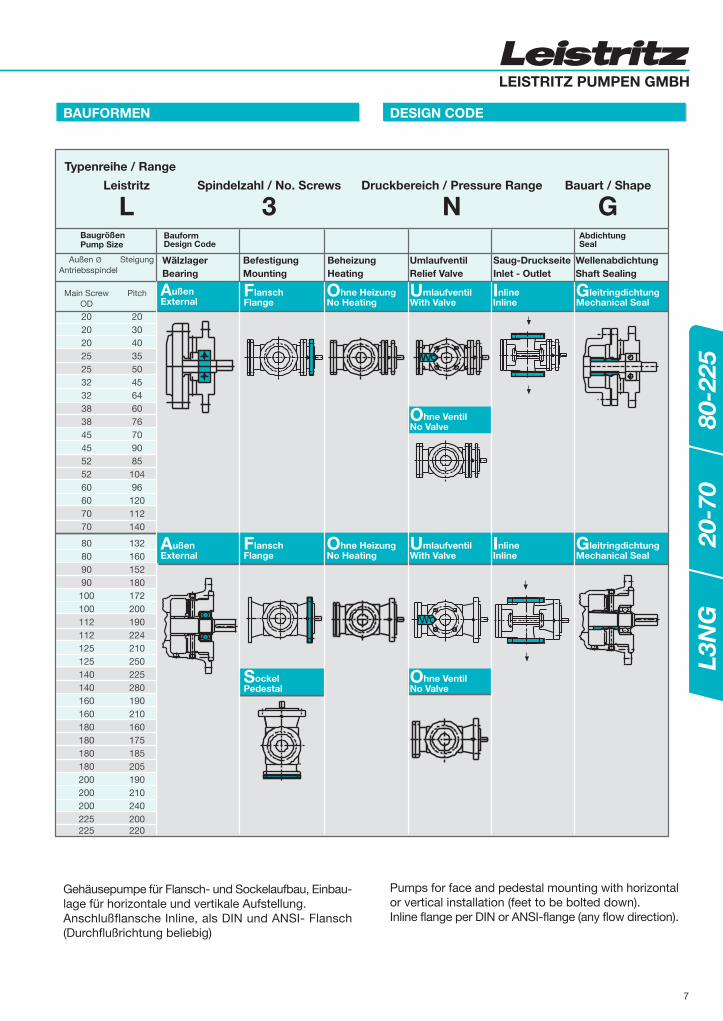
BAUFORMEN DESIGN CODE
Gehäusepumpe für Flansch- und Sockelaufbau, Einbau-lage für horizontale und vertikale Aufstellung.Anschlußflansche Inline, als DIN und ANSI- Flansch(Durchflußrichtung beliebig)
Pumps for face and pedestal mounting with horizontalor vertical installation (feet to be bolted down).Inline flange per DIN or ANSI-flange (any flow direction).
L3N
G20
-70
80-2
25
7
AußenExternal
FlanschFlange
Ohne HeizungNo Heating
UmlaufventilWith Valve
InlineInline
GleitringdichtungMechanical Seal
Ohne VentilNo Valve
Ohne VentilNo Valve
SockelPedestal
GleitringdichtungMechanical Seal
Außen Ø SteigungAntriebsspindel
Main Screw PitchOD
20 2020 3020 4025 3525 5032 4532 6438 6038 7645 7045 9052 8552 10460 9660 12070 11270 140
80 13280 16090 15290 180100 172100 200112 190112 224125 210125 250140 225140 280160 190160 210180 160180 175180 185180 205200 190200 210200 240225 200225 220
Bauform AbdichtungDesign Code Seal
Wälzlager Befestigung Beheizung Umlaufventil Saug-Druckseite WellenabdichtungBearing Mounting Heating Relief Valve Inlet - Outlet Shaft Sealing
Typenreihe / Range
Leistritz Spindelzahl / No. Screws Druckbereich / Pressure Range Bauart / Shape
L 3 N G
AußenExternal
FlanschFlange
Ohne HeizungNo Heating
InlineInline
UmlaufventilWith Valve
BaugrößenPump Size
8
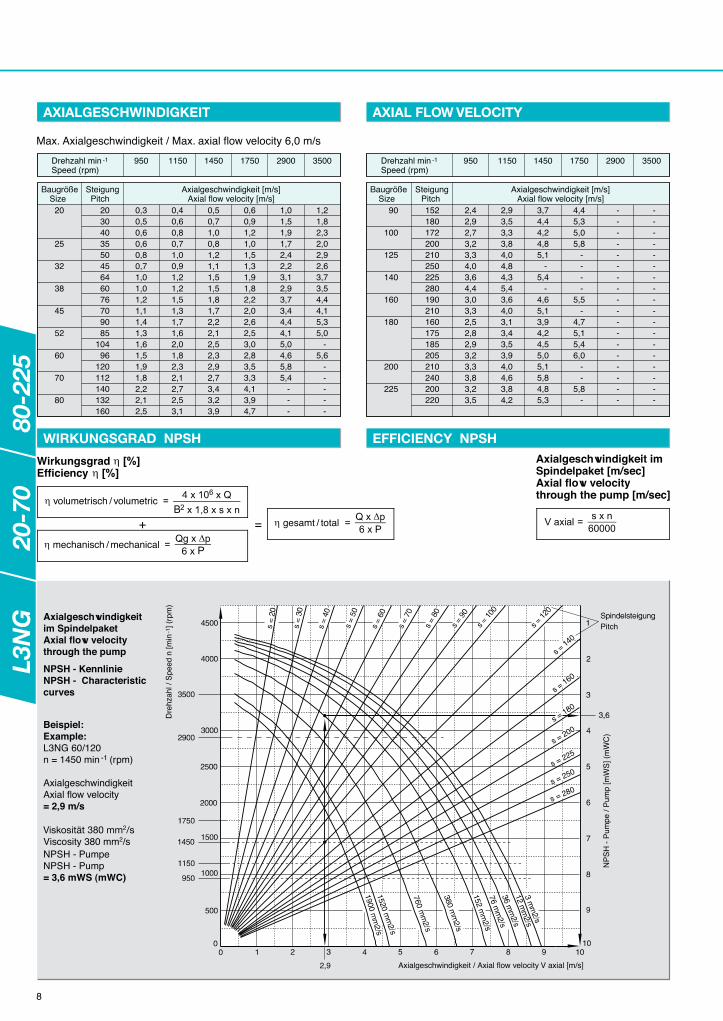
Axialgeschwindigkeitim SpindelpaketAxial flow velocitythrough the pump
NPSH - KennlinieNPSH - Characteristiccurves
Beispiel:Example:L3NG 60/120n = 1450 min -1 (rpm)
AxialgeschwindigkeitAxial flow velocity= 2,9 m/s
Viskosität 380 mm2/sViscosity 380 mm2/sNPSH - PumpeNPSH - Pump= 3,6 mWS (mWC)
Max. Axialgeschwindigkeit / Max. axial flow velocity 6,0 m/s
AXIALGESCHWINDIGKEIT AXIAL FLOW VELOCITY
WIRKUNGSGRAD NPSH EFFICIENCY NPSH
SteigungPitch
BaugrößeSize
20
25
32
38
45
52
60
70
80
Axialgeschwindigkeit [m/s]Axial flow velocity [m/s]
203040355045646076709085
10496
120112140132160
0,30,50,60,60,80,71,01,01,21,11,41,31,61,51,91,82,22,12,5
0,40,60,80,71,00,91,21,21,51,31,71,62,01,82,32,12,72,53,1
0,50,71,00,81,21,11,51,51,81,72,22,12,52,32,92,73,43,23,9
0,60,91,21,01,51,31,91,82,22,02,62,53,02,83,53,34,13,94,7
1,01,51,91,72,42,23,12,93,73,44,44,15,04,65,85,4 - - -
1,21,82,32,02,92,63,73,54,44,15,35,0 -5,6 - - - - -
Drehzahl min -1Speed (rpm)
950 1150 1450 1750 2900 3500
SteigungPitch
BaugrößeSize
90
100
125
140
160
180
200
225
Axialgeschwindigkeit [m/s]Axial flow velocity [m/s]
152180172200210250225280190210160175185205210240200220
2,42,92,73,23,34,03,64,43,03,32,52,82,93,23,33,83,23,5
2,93,53,33,84,04,84,35,43,64,03,13,43,53,94,04,63,84,2
3,74,44,24,85,1 -5,4 -4,65,13,94,24,55,05,15,84,85,3
4,45,35,05,8 - - - -5,5 -4,75,15,46,0 - -5,8 -
- - - - - - - - - - - - - - - - - -
- - - - - - - - - - - - - - - - - -
Drehzahl min -1Speed (rpm)
950 1150 1450 1750 2900 3500
Pitch
Axialgeschwindigkeit / Axial flow velocity V axial [m/s]
Dre
hzah
l / S
peed
n [m
in -1
] (rp
m)
s = 160
s = 280s = 250s = 225
s = 200s =
180
NP
SH
- P
umpe
/ P
ump
[mW
S] (
mW
C)
Axialgeschwindigkeit imSpindelpaket [m/sec]Axial flow velocitythrough the pump [m/sec]
mechanisch / mechanical
volumetrisch / volumetric
gesamt / total
WirkungsgradEfficiency
+ =
L3N
G20
-70
80-2
25
LEISTRITZ PUMPEN GMBH
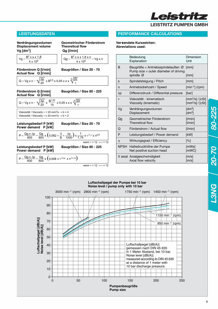
VerdrängungsvolumenDisplacement volume
Geometrischer FörderstromTheoretical flow
Förderstrom Q [l/min]Actual flow Q [l/min]
Baugrößen / Size 20 - 70
Förderstrom Q [l/min]Actual flow Q [l/min]
Baugrößen / Size 80 - 225
Leistungsbedarf P [kW]Power demand P [kW]
Baugrößen / Size 20 - 70
Leistungsbedarf P [kW]Power demand P [kW]
Baugrößen / Size 80 - 225
Viskosität / ViscosityViskosität / Viscosity
0,008
15
1,22
1 2,8 1 1,75
Verwendete Kurzzeichen:Abreviations used:
B
s
n
p
Vg
Qg
Q
P
NPSH
V axial
Baugröße = AntriebsspindelaußenPump size = outer diameter of drivingspindle
Spindelsteigung / Pitch
Antriebsdrehzahl / Speed
Differenzdruck / Differential pressure
Viskosität - kinematischViscosity (kinematic)
VerdrängungsvolumenDisplacement
Geometrischer FörderstromTheoretical flow
Förderstrom / Actual flow
Leistungsbedarf / Power demand
Wirkungsgrad / Efficiency
Haltedruckhöhe der PumpeNet positive suction head
AxialgeschwindigkeitAxial flow velocity
[mm]
[mm]
[mm]
[min-1] (rpm)
[bar]
[mm /s] / [cSt][mm /s] / [cSt]
[dm3][dm3]
[l/min][l/min]
[l/min]
[kW]
[%]
[mWs][mWC]
[m/s][m/s]
BedeutungExplanation
DimensionUnit
100
90
80
70
60
50
40
30
20
10
00 50 100 150 200 250
3500 min -1 (rpm) 2900 min -1 (rpm) 1750 min -1 (rpm) 1450 min -1 (rpm)
Luftschallpegel der Pumpe bei 10 barNoise level / pump only with 10 bar
PumpenbaugrößePump size
Lu
ftsc
hal
lpeg
el [
dB
(A)]
No
ise
leve
l [d
B(A
)]
Luftschallpegel [dB(A)]gemessen nach DIN 45 635in 1 Meter Abstand, bei 10 bar.Noise level [dB(A)]measured according to DIN 45 635at a distance of 1 meter with10 bar discharge pressure.
1150 min -1 (rpm)
950 min -1 (rpm)
9
LEISTUNGSDATEN PERFORMANCE CALCULATIONS
L3N
G20
-70
80-2
25

SCHNITTZEICHNUNG
10
Die komplette Pumpe kann in jeder Lage eingebaut werden.The complete pump can be installed in each position.
Ausführung mit VentilExecution with valve
Ausführung ohne VentilExecution without valve
Ausführung: Mit nachschmier-barem KugellagerExecution with regreaseableball bearing
Ausführung:Mit HutmutterTemperaturüber 100°CDesign: with capnut temp. >100°C
SECTIONAL DRAWING
Ausführung: Mit ÖlvorlageExecution with static oil quench
SchnittzeichnungenSectional drawingsE 160 6878E 160 7022E 160 7610
TypenreiheRange
L3N
BauartType
G
BaugrößeSize
20 - 70
SteigungPitch
/ ...
BauformShape
AFOOIAFOUI
AbdichtungType of seal
GG
AusführungIdentification
3-Spindelpumpe / 3-Spindle encased pumpFlanschbefestigung / with flangeKugellager außen / External ball bearing
BemerkungRemarks
PumpengehäuseVerschlußschraubeDichtringDeckel endseitigFlachdichtungZylinderschraubeÖlstandsbehälterDeckel antriebsseitigZylinderschraubePaßkerbstiftGleitringdichtungVerschlußschraubeDichtringWellendichtringKugelschmiernippelAntriebsspindelLaufspindel
156
30313238455061626970
116120150151
RillenkugellagerStützscheibeSicherungsringSicherungsringLabyrinthringDistanzringPaßfederSechskantmutterDichtringVentilkegelFedertellerStellschraubeVentilfederSeal-Lock-MutterRohrVerschraubung - Gerade - EinVerschraubung - Gerade - Auf
170172173174175178180215216219220222235281345350351
Pump casingLocking screwSealing ringCoverGasketMounting screwOil level gauge glassCover driving sideMounting screwEdged adjusting pinMechanical sealLocking screwSealing ringShaft sealLubrication nippleDriving spindleIdler spindle
156
30313238455061626970
116120150151
Grooved ball bearingSupporting diskCirclipCirclipIntermediate ringSpacer ringKeyHexagonal nutSealing ringValve coneSpring PlateAdjusting screwValve springSeal-lock-nut or cap nutPipeMale stud couplingFemale stud coupling
170172173174175178180215216219220222235281345350351
215216281
38
38
175 178
120
(50)
69, 70
350
345
351
L3N
G20
-70
80-2
25

LEISTRITZ PUMPEN GMBH
11
MASSBLATT PUMP DIMENSIONS
Die komplette Pumpe kann in jeder Lage eingebaut werden.The complete pump can be installed in each position.
PumpenmaßblätterDimensional drawingsE 168 5954E 168 6531
TypenreiheRange
L3N
BauartType
G
BaugrößeSize
20 - 70
SteigungPitch
/ ...
BauformShape
AFOOIAFOUI
AbdichtungType of seal
GG
AusführungIdentification
3-Spindelpumpe / 3-Spindle encased pumpFlanschbefestigung / with flangeKugellager außen / External ball bearing
BemerkungRemarks
Maße in mmDimensions in mm
Durchflußrichtung: = Pfeilrichtung Flow direction: Direction of arrow
Saug- DruckflanschPN 16 DIN 2533Suction and dischargeflange PN 16 DIN 2533
Entleerungs- oderMeßanschluß R1Suction sidedrain- or measuringconnection R1
Entfällt beiAusführungohne VentilInapplicablefor designwithout valve
Max. zul. Kräfte und Momentean den AnschlußflanschenSauganschluß - DruckanschlußMax. allowable resultant forcesand moments on pump nozzlesSuction flange - Pressure flange
b b1 L l1 l5 l6 l7 l8 l20 d2h6 d3 4 x d5 d4 dk6 t u R1 DN S S1 S2 S3 S4 S5 S6 F x, y, z
150 75 250 141 23 32 10 7 40 80 103 9 125 14 16 5 G1/4 25 115 85 14 4 16 2 68 225 N 125
150 75 250 141 23 32 10 7 40 80 103 9 125 14 16 5 G1/4 25 115 85 14 4 16 2 68 225 N 125
170 85 271 164 23 32 10 7 40 80 103 9 125 14 16 5 G1/4 32 140 100 18 4 18 2 78 288 N 160
220 110 343 194 30 41 14 9 40 100 125 11 160 19 21,5 6 G1/4 50 165 125 18 4 20 3 102 450 N 250
220 110 370 194 30 41 14 9 40 100 125 11 160 19 21,5 6 G1/4 50 165 125 18 4 20 3 102 450 N 250
250 125 453 249 40 52 16 9 40 125 160 14 200 28 31 8 G1/2 80 200 160 18 8 22 3 138 720 N 400
250 125 448 249 40 52 16 9 40 125 160 14 200 28 31 8 G1/2 80 200 160 18 8 22 3 138 720 N 400
270 135 516 270 40 52 18 9 40 160 200 18 250 32 35 10 G1/2 100 220 180 18 8 24 3 158 900 N 500
PumpenmaßePump dimensions
AnbauflanschMounting flange
Wellenende AnschlüsseShaft and Connect.
Saugflansch und Druckflansch Kräfte und MomenteForces and Moments
PumpePumpBaugr.Size
020
025
032
038
045
052
060
070
M x, y, z
Nm
Nm
Nm
Nm
Nm
Nm
Nm
Nm
Suction and Discharge flange DIN 2533
[kg]
10
11
13
26
27
43
45
71
GewichtWeight
L3N
G20
-70
80-2
25
12
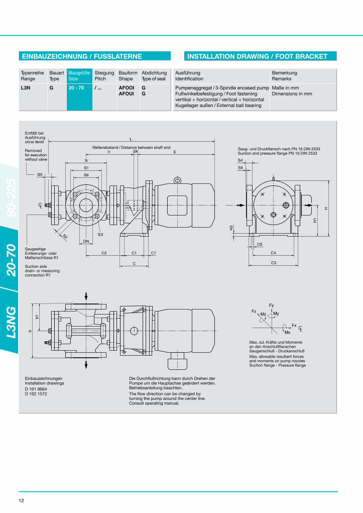
EINBAUZEICHNUNG / FUSSLATERNE INSTALLATION DRAWING / FOOT BRACKET
EinbauzeichnungenInstallation drawingsD 161 9664D 162 1572
Die Durchflußrichtung kann durch Drehen derPumpe um die Hauptachse geändert werden.Betriebsanleitung beachten.The flow direction can be changed byturning the pump around the center line.Consult operating manual.
TypenreiheRange
L3N
BauartType
G
BaugrößeSize
20 - 70
SteigungPitch
/ ...
BauformShape
AFOOIAFOUI
AbdichtungType of seal
GG
AusführungIdentification
Pumpenaggregat / 3-Spindle encased pumpFußwinkelbefestigung / Foot fasteningvertikal + horizontal / vertical + horizontalKugellager außen / External ball bearing
BemerkungRemarks
Maße in mmDimensions in mm
Saug- und Druckflansch nach PN 16 DIN 2533Suction and pressure flange PN 16 DIN 2533
Wellenabstand / Distance between shaft end
Entfällt beiAusführungohne Ventil
Removedfor executionwithout valve
SaugseitigeEntleerungs- oderMeßanschlüsse R1
Suction sidedrain- or measuringconnection R1
Max. zul. Kräfte und Momentean den AnschlußflanschenSauganschluß - DruckanschlußMax. allowable resultant forcesand moments on pump nozzlesSuction flange - Pressure flange
L3N
G20
-70
80-2
25
LEISTRITZ PUMPEN GMBH
MotorMotorBaugr.Size
FußmaßeFoot dimensions
HöhenmaßeHeight
Anschl.Connect.
Saugflansch und Druckflansch Kräfte u. MomenteForces + Moments
PumpenmaßePump dimensions
LängeLength
PumpePumpBaugr.Size
Suction and Discharge flange DIN 2533
13
L3N
G20
-70
80-2
25

14
Drehzahl / Speed 1450 min -1 (rpm) Drehzahl / Speed 2900 min -1 (rpm)
Pumpe /PumpBaugröße
SizeSteigung
Pitch
Förder-druck
Different.pressurep [bar]
Kinematische Viskosität / Viscosity (kinematic) (mm /s) Pumpe /PumpBaugröße
SizeSteigung
Pitch
Förder-druck
Different.pressurep [bar]
Kinematische Viskosität / Viscosity (kinematic) (mm /s)
Detailierte Leistungsdaten in Abhängigkeit der Pumpendrehzahl und der Viskosität, auch für andere Viskositäten und Druckbereiche, sind den Einzelkennlinien zu entnehmen.Detailed power data depending upon pump speed and viscosity. The respective curves shall be used for other viscosities and pressure range.
Q [l/min] P [kW] Q [l/min] P [kW] Q [l/min] P [kW] Q [l/min] P [kW] Q [l/min] P [kW] Q [l/min] P [kW]
FÖRDERSTROM / LEISTUNGSTABELLE FLOW AND POWER DATA TABLES50 Hz 50 Hz
L3N
G20
-70
80-2
25

LEISTRITZ PUMPEN GMBH
15
Pumpe/PumpBaugröße
SizeSteigung
Pitch
Förder-druck
Different.pressurep [bar]
Kinematische Viskosität / Viscosity (kinematic) (mm /s) Pumpe/ PumpBaugröße
SizeSteigung
Pitch
Förder-druck
Different.pressurep [bar]
Kinematische Viskosität / Viscosity (kinematic) (mm /s)
Drehzahl / Speed 1750 min -1 (rpm) Drehzahl / Speed 3500 min -1 (rpm)
Detailierte Leistungsdaten in Abhängigkeit der Pumpendrehzahl und der Viskosität, auch für andere Viskositäten und Druckbereiche, sind den Einzelkennlinien zu entnehmen.Detailed power data depending upon pump speed and viscosity. The respective curves shall be used for other viscosities and pressure range.
FÖRDERSTROM / LEISTUNGSTABELLE FLOW AND POWER DATA TABLES60 Hz 60 Hz
L3N
G20
-70
80-2
25
Q [l/min] P [kW] Q [l/min] P [kW] Q [l/min] P [kW] Q [l/min] P [kW] Q [l/min] P [kW] Q [l/min] P [kW]
Ausführung mit ÖlvorlageExecution with static oil quench
52
Ausführung ohne VentilExecution without valve
Y
Valve executionfor size 80 and 90
Ventilausführung fürBaugröße 80 und 90
4
3
63
62
61
Ausführung abBaugröße 200
Execution fromsize 200
61
W
52313120312
Nur bei Ausführung mitnachschmierbarem Kugellager
175
178
Execution only withregreasable ball bearing
Z
Ausführung mit gesicherterSeal-Lock-Mutter
Execution with securedseal-lock-nut
X281
216
215
215
281
216X
Ventilausführung fürTemperaturen > 120°C
Valve execution fortemperatures > 120°C
348
352
350
357
V
354
356
355
37
36
40
31
1
150
151
56
179 17247 45 174173180 172170
ab Baugröße 125from size 125
bis Baugröße 112up to size 112
CL
69
70
32
46
4
3
219
235
220
281
222
277
56
Y
X
Z
V
W
Schnittzeichnung / Sectional drawing C 160 7631
16
SCHNITTZEICHNUNG / SOCKELPUMPE SECTIONAL DRAWING / PEDESTAL PUMP
TypenreiheRange
L3N
BauartType
G
BaugrößeSize
80 - 225
SteigungPitch
/ ...
BauformShape
ASOOIASOUI
AbdichtungType of seal
GG
AusführungIdentification
3-spindelige Sockelpumpe3-spindle pedestal pumpKugellager außen / External ball bearingmit / ohne Ventil / with / without valve
BemerkungRemarks
173174175178179180215216219220222235277281
312313348350352354355356357
CirclipCirclipIntermediate ringLabyrinth bushingSpacer ringKeyNutSealing ringValve coneSpring plateAdjusting screwValve springRebounding plateSeal-lock-nutCup nutSocketNippleOil boxDouble nippleReducing socketExtension tubeLocking screwSealing ringAngular connection
13456
3132363740454647526162636970
120150151170172
Pump casingLocking screwSealing ringLocking screwSealing ringGasketMounting screwLocking screwSealing ringPedestalCover driving sideO-ringMounting screwShaft sealing ringEdged adjusting pinMechanical sealSpacer ringLocking screwSealing ringConical lubricating headDriving spindleIdler spindleGrooved ball bearingSupporting disk
173174175178179180215216219220222235277281
312313348350352354355356357
SicherungsringSicherungsringZwischenringLabyrinthringDistanzringPaßfederSechskantmutterDichtringVentilkegelFedertellerStellschraubeVentilfederPralltellerSeal-Lock-MutterHutmutterMuffeRohrdoppelnippelÖlstandsbehälterDoppelnippelReduktionsmuffeVerlängerungVerschlußschraubeDichtringWinkelverschraubung
PumpengehäuseVerschlußschraubeDichtringVerschlußschraubeDichtring/SicherungsblechFlachdichtungZylinderschraubeVerschlußschraubeDichtringSockelDeckel, antriebsseitigO-RingZylinderschraubeWellendichtringKerbstiftGleitringdichtungDistanzringVerschlußschraubeDichtringKegelwulst-SchmierkopfAntriebsspindelLaufspindelRillenkugellagerStützscheibe
13456
3132363740454647526162636970
120150151170172
L3N
G20
-70
80-2
25
LEISTRITZ PUMPEN GMBH
l6
l7
l8
CL
S3 = Anzahl der BohrungenS3 = Number of bore-holes
b1
b
R1 ManometeranschlußR1 Pressure gauge connection
R1 VakuummeteranschlußR1 Vacuum gauge connection
S4
L
LC
S3 = Anzahl der BohrungenS3 = Number of bore-holes
l5
l1
S4
l7
ød6 ød7
WellenendeShaft end
u
t
WelleShaft
Max. zul. Kräfte und Momentean den AnschlußflanschenSauganschluß - DruckanschlußMax. allowable resultant forcesand moments on pump nozzlesSuction flange - Pressure flange
PumpenmaßblätterDimensional drawingsD 168 6393D 168 6394D 168 6395D 168 6431D 168 6446
17
MASSBLATT / SOCKELPUMPE PUMP DIMENSIONS / PEDESTAL PUMP
t
45.0
51.5
74.5
79.5
85.0
u
12
14
20
20
22
R1
G1/2
G1/2
G1/2
G1/2
G1/2
S
285
343
406
433
534
S4
26
30
32
32
36
S1
240
295
355
410
470
S2
22
22
25
26
26
S2
22.4
22.4
25.4
25.4
28.4
DIN 2533Mx,y,z
750
1000
1250
1500
1500
TypenreiheRange
L3N
BauartType
G
BaugrößeSize
80 - 225
SteigungPitch
/ ...
BauformShape
ASOOIASOUI
AbdichtungType of seal
GG
AusführungIdentification
3-spindelige Sockelpumpe3-spindle pedestal pumpKugellager außen / External ball bearingmit / ohne Ventil / with / without valve
BemerkungRemarks
Maße in mmDimensions in mm
PumpePump
BaugrößeSize
PumpenmaßePump dimensions
AnbauflanschMounting flange
80 + 90
100 + 112
125 + 140
160 + 180
200 + 225
SockelanschlüssePedestal dimens.
Wellenende Anschl.Shaft and Connect.
Saugflansch und DruckflanschSuction and Discharge flange
GewichtWeight
Kräfte und MomenteForces and Moments
S3
8
8
12
12
12
S1
241,3
298,5
382,0
431,8
476,3
S3
8
12
12
12
16
DN
150
200
250
300
350
b
420
500
620
720
800
b1
210
250
310
360
400
L
702
822
987
1007
1074
l1
415
480
570
590
622
l5
60
90
100
100
110
l6
70
100
110
110
122
l7
28
28
33
38
40
l8
6
6
6
6
8
Ød2h6
225
275
340
415
500
Ød3
280
330
420
500
590
8 x d5
22
22
26
26
30
d4
320
380
470
580
650
d6
360
440
550
650
700
d7
400
500
620
720
760
d8
22
22
26
26
30
h3
25
30
35
35
40
dk6
42
48
70
75
80
ANSI[kg]
200
300
450
785
1200
Fx,y,z
1350
1800
2250
2700
2700
L3N
G20
-70
80-2
25
Saug- und DruckflanschSuction and discharge flange
D3 = Anzahl der Bohrungen
Anordnungbei 12 Loch
Anordnungbei 8 Loch
DN = NennweitePN = Nenndruck
D3 = Number of bore holes
Arrangementfor 12 holes
Arrangementfor 8 holes
DN = Diam. nominalPN = Press. nom.
D
D2
DN
D1 Saugflansch
Suction flange
Druckflanschdischarge flange
Vakuummeter-anschluß RVacuum gaugeconnection R
Manometer-anschluß RPressure gaugeconnection R
b
D4
b1
D4
s
l9
h
Wel
lene
nden
abst
and
Dis
tanc
e b
etw
een
shaf
t en
ds
l
LC
E+
50
0
Max. zul. Kräfte und Momentean den AnschlußflanschenSauganschluß - DruckanschlußMax. allowable resultant forcesand moments on pump nozzlesSuction flange - Pressure flange
18
EINBAUZEICHNUNG / SOCKELPUMPE INSTALLATION DRAWING / PEDESTAL PUMP
EinbauzeichnungInstallation drawingD 162 1327
Die Durchflußrichtung kann durch Drehen der Pumpe um dieHauptachse geändert werden. Betriebsanleitung beachten.
The flow direction can be changed by turning the pumparound the center line. Consult operating manual.
TypenreiheRange
L3N
BauartType
G
BaugrößeSize
80 - 225
SteigungPitch
/ ...
BauformShape
ASOOIASOUI
AbdichtungType of seal
GG
AusführungIdentification
3-spindelige Sockelpumpe3-spindle pedestal pumpKugellager außen / External ball bearingmit / ohne Ventil / with / without valve
BemerkungRemarks
Maße in mmDimensions in mm
BaugrößeSize
PumpePump
LängeLength
L
SockelmaßePedestal dimensions
d680 + 90
100 + 112
125 + 140
160 + 180
200 + 225
132S132M160M160L180M180L200L225S225M160M160L180M180L200L225S225M250M280S280M180L200L225S225M250M280S280M315S315M315L200L225S225M250M280S280M315S315M315L355M225M250M280S280M315S315M315L355M355L400M
1349134915211521159115911631167316731666166617361736177818181818194520252065195019902030203021552235227524302480251520152055205521802260230024502500253527702122224223222362251725672597283228373153
540540710710780780820860860710710780780820860860980
10601100
780820880880980
10601100125013001330
820860860980
106011001250130013301565
860980
10601100125013001330156515651881
360
440
550
650
700
d7400
500
620
720
760
d822
22
26
26
30
h25
30
35
35
40
s24242626262626282826262626282828353535303030303535354040453535354040404040454540404040454545455050
b420
500
620
720
800
b1210
250
310
360
400
l785
930
1140
1150
1222
l9370
450
570
570
600
RG 1/2
G 1/2
G 1/2
G 1/2
G 1/2
DN150
200
250
300
350
D285
343
406
483
534
D1240
295
355
410
470
D222
22
26
26
26
D38
12
12
12
16
D426
30
32
32
36
DN6
8
10
12
14
D285
343
406
483
534
D1241.3
296.5
362
431.8
476.3
D222.4
22.4
25.4
25.4
28.4
D38
8
12
12
12
D426
30
32
32
36
Fx,y,z[N]1350
1800
2250
2700
2700
Mx,y,z[Nm]750
1000
1250
1500
1500
MotorIEC
MotorIEC E
7080
120135180190260315335120135180190260315335440615655190360315335440515655925
10901170260315335440615655925
109011701730
335440615655925
10901170173018603010
PumpenmaßePump dimensions
Anschl.Connect.
Saug- / DruckflanschSuction / Discharge flange
Kräfte u. Mom.Forces + Mom.
DIN 2533
Saug- / DruckflanschSuction / Discharge flange
ANSI ISO lbs
000[kg]
200
300
450
785
1200
Pump[kg]
Gewicht /WeightPumpe
[kg]
MotorMotor
[kg]
LaterneBracket
[kg]
Kuppl.Coupl.
kpl.
3344444554444555
101212
88
12121212121818261212121818181818323218181818282828323535
L3N
G20
-70
80-2
25
LEISTRITZ PUMPEN GMBH
4 3 63 62 6136 31 1 150 1515 6
179
172
47
45
174
173
180
172
170
ab Baugröße 125from size 125
bis Baugröße 112until size 112
CL
697032 464 3219235220281222 30 2775 6
YX
ZV
W
52
313
120
312
Nur bei Ausführung mitnachschmierbaremKugellager
175
178
Execution only withregreasable ball bearing
ZAusführung ohne VentilExecution without valveY
Valve executionfor size 80 and 90
Ventilausführung fürBaugröße 80 und 90
Ausführung: mit gesicherterSeal-Lock-Mutter
Execution with securedseal-lock-nut
X
281216215 215281 216
X
Ventilausführung fürTemperaturen > 120°C
Valve execution fortemperatures > 120°C
Ausführung abBaugröße 200
Execution fromsize 200
61
W
Ausführung mit ÖlvorlageExecution withstatic oil quench
52
V
354
348
352
350
37
36
356
355
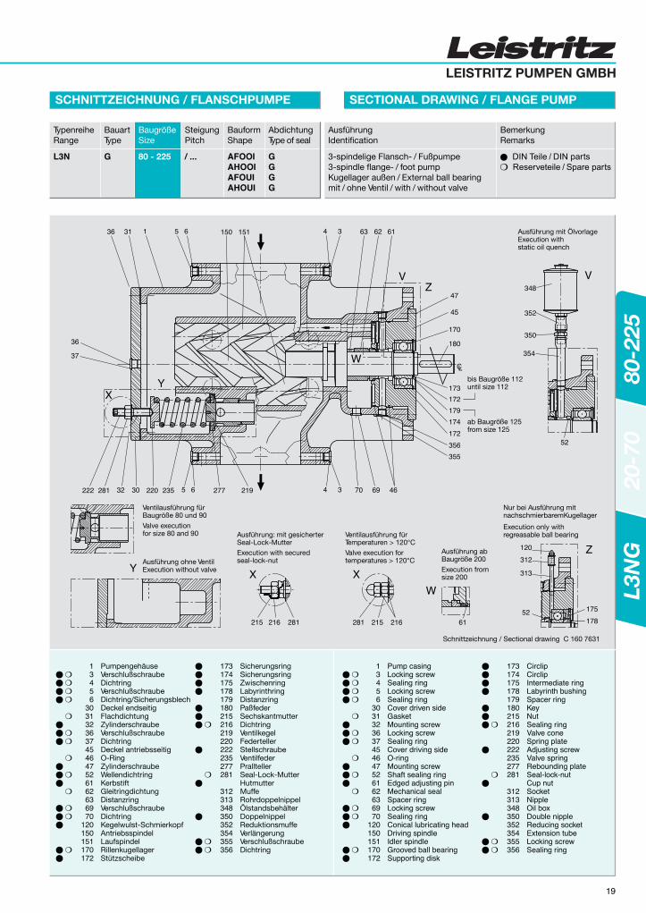
Schnittzeichnung / Sectional drawing C 160 7631
19
SCHNITTZEICHNUNG / FLANSCHPUMPE SECTIONAL DRAWING / FLANGE PUMP
TypenreiheRange
L3N
BauartType
G
BaugrößeSize
80 - 225
SteigungPitch
/ ...
BauformShape
AFOOIAHOOIAFOUIAHOUI
AbdichtungType of seal
AusführungIdentification
3-spindelige Flansch- / Fußpumpe3-spindle flange- / foot pumpKugellager außen / External ball bearingmit / ohne Ventil / with / without valve
BemerkungRemarks
GGGG
173174175178179180215216219220222235277281
312313348350352354355356
CirclipCirclipIntermediate ringLabyrinth bushingSpacer ringKeyNutSealing ringValve coneSpring plateAdjusting screwValve springRebounding plateSeal-lock-nutCup nutSocketNippleOil boxDouble nippleReducing socketExtension tubeLocking screwSealing ring
13456
3031323637454647526162636970
120150151170172
Pump casingLocking screwSealing ringLocking screwSealing ringCover driven sideGasketMounting screwLocking screwSealing ringCover driving sideO-ringMounting screwShaft sealing ringEdged adjusting pinMechanical sealSpacer ringLocking screwSealing ringConical lubricating headDriving spindleIdler spindleGrooved ball bearingSupporting disk
173174175178179180215216219220222235277281
312313348350352354355356
SicherungsringSicherungsringZwischenringLabyrinthringDistanzringPaßfederSechskantmutterDichtringVentilkegelFedertellerStellschraubeVentilfederPralltellerSeal-Lock-MutterHutmutterMuffeRohrdoppelnippelÖlstandsbehälterDoppelnippelReduktionsmuffeVerlängerungVerschlußschraubeDichtring
PumpengehäuseVerschlußschraubeDichtringVerschlußschraubeDichtring/SicherungsblechDeckel endseitigFlachdichtungZylinderschraubeVerschlußschraubeDichtringDeckel antriebsseitigO-RingZylinderschraubeWellendichtringKerbstiftGleitringdichtungDistanzringVerschlußschraubeDichtringKegelwulst-SchmierkopfAntriebsspindelLaufspindelRillenkugellagerStützscheibe
13456
3031323637454647526162636970
120150151170172
L3N
G20
-70
80-2
25

ød4
l7
l8
l5
CL
S3 = Anzahl der BohrungenS3 = Number of bore-holes
l1
S3 = Anzahl der BohrungenS3 = Number of bore-holes
b1
b b2S
4
R1 = ManometeranschlußR1 = Pressure gauge connection
R1 = VakuummeteranschlußR1 = Vacuum gauge connection
S4 øS1
d1l4
h2
l2
LC
Ll20
l6
PumpenmaßblätterDimensional drawingsD 168 6393D 168 6394D 168 6395
D 168 6431D 168 6446
WelleShaft
20
MASSBLATT / FLANSCHPUMPE PUMP DIMENSIONS / FLANGE PUMP
t
45.0
51.5
74.5
79.5
85.0
R1
G1/2
G1/2
G1/2
G1/2
G1/2
S
285
343
406
433
534
S1
240
295
355
410
470
S2
22.4
22.4
25.4
25.4
28.4
DIN 2533Mx,y,z
750
1000
1250
1500
1500
S4
26
30
32
32
36
u
12
14
20
20
22
S2
22
22
25
26
26
WellenendeShaft end
u
t
TypenreiheRange
L3N
BauartType
G
BaugrößeSize
80 - 225
SteigungPitch
/ ...
BauformShape
AFOOIAHOOIAFOUIAHOUI
AbdichtungType of seal
GGGG
AusführungIdentification
3-spindelige Flansch- / Fußpumpe3-spindle flange- / foot pumpKugellager außen / External ball bearingmit / ohne Ventil / with / without valve
BemerkungRemarks
Maße in mmDimensions in mm
PumpePump
BaugrößeSize
PumpenmaßePump dimensions
80 + 90
100 + 112
125 + 140
160 + 180
200 + 225
Wellenende Anschl.Shaft and Connect.
Saugflansch und DruckflanschSuction and Discharge flange
GewichtWeight
Kräfte und MomenteForces and Moments
S3
8
8
12
12
12
S1
241.3
298.5
382.0
431.8
476.3
DN
150
200
250
300
350
b
420
500
620
720
800
b1
210
250
310
360
400
dk6
42
48
70
75
80
ANSI
AnbauflanschMounting flange
225
275
340
415
500
280
330
420
500
590
8 x d5
22
22
26
26
30
d4
320
380
470
580
650
b2
120
120
150
150
170
h2
150
180
215
270
315
l1
415
480
570
590
622
L
702
822
987
1007
1074
l2
240
240
300
300
350
l4
295
360
420
440
447
[kg]
200
300
450
785
1200
Fx,y,z
1350
1800
2250
2700
2700
S3
8
12
12
12
16
d1
M20
M20
M24
M24
M27
l20
51
55
93
100
100
l8
6
6
6
6
8
l7
28
28
33
36
40
l6
70
100
110
110
122
l5
60
90
100
100
110
Max. zul. Kräfte und Momentean den AnschlußflanschenSauganschluß - DruckanschlußMax. allowable resultant forcesand moments on pump nozzlesSuction flange - Pressure flange
L3N
G20
-70
80-2
25

LEISTRITZ PUMPEN GMBH
Saug- und DruckflanschSuction and discharge flange
D3 = Anzahl der Bohrungen
Anordnungbei 12 Loch
Anordnungbei 8 Loch
DN = NennweitePN = Nenndruck
D3 = Number of bore holes
Arrangementfor 12 holes
Arrangementfor 8 holes
DN = Diam. nominalPN = Press. nom.
D
D2
DN
D1
s
Wel
lene
nden
abst
and
Dis
tanc
e b
etw
een
shaf
t en
ds
l
C2
C2
C1 C
H2
H4
C3
H1
H
max.
l20
L
E+
50
l9
0
SaugflanschSuction flange
Druckflanschdischarge flange
Vakuummeter-anschluß RVacuum gaugeconnection R
Manometer-anschluß RPressure gaugeconnection R
b
D4
b1
D4
LC
Max. zul. Kräfte und Momentean den AnschlußflanschenSauganschluß - DruckanschlußMax. allowable resultant forcesand moments on pump nozzlesSuction flange - Pressure flange
C4
C5
Baugr.Size
PumpePump
LängeLength
L
FußmaßeFoot dimensions
C80+90
100+112
125+140
160+180
200+225
132S132M160M160L180M180L200L225S225M160M160L180M180L200L225S225M250M280S280M180L200L225S225M250M280S280M315S315M315L200L225S225M250M280S280M315S315M315L355M225M250M280S280M315S315M315L355M355L400M
1266126614381438150815081548159015901558155816281628167017101710183719171957179718371877187720022082212222772327236217521792179219171997203721872237227225071852197220522092224722972327256225672883
540540710710780780820860860710710780780820860860980
10601100
780820860860980
10601100125013001330
820860860980
106011001250130013301565
860980
10601100125013001330156515651881
**330330330330330380380**360360360410410420420
****430430430*********500500************
C1
280280280280280320320
310310310350350360360
370370370
430430
C2
-----160160
155155155175175180180
185185185
215215
C3
308308308308308304304
343343344339339337.5337.5
417.5417.5417.5
425425
C4
390390390390420470470
420420420470470570570
570570570
680680
b420
500
620
720
800
b1210
250
310
360
400
l702
822
987
897
952
l9287
342
417
417
452
RG1/2
G1/2
G1/2
G1/2
G1/2
DN150
200
250
300
350
D285
343
406
483
534
D1240
295
355
410
470
D222
22
26
26
26
D38
12
12
12
16
D426
30
32
32
36
DN6
8
10
12
14
D285
343
406
483
534
D1241.3
298.5
362
431.8
476.3
D222.4
22.4
25.4
25.4
28.4
D38
8
12
12
12
D426
30
32
32
36
Fx,y,z[N]1350
1800
2250
2700
2700
Mx,y,z[Nm]750
1000
1250
1500
1500
MotorIEC
MotorIEC E
7080
120135180190260315335120135180190260315335440615655190360315335440615655925
10901170
260315335440615655925
109011701730
335440615655925
10901170173018603010
PumpenmaßePump dimensions
Anschl.Connect.
Saug- / DruckflanschSuction/ Discharge flange
Kräfte + Mom.Forces + Mom.
DIN 2533
Saug- / DruckflanschSuction / Discharge flange
ANSI ISO Ibs
000[kg]
200
300
450
785
1200
Pump[kg]
Gewicht / WeightPumpe
[kg]
MotorMotor
[kg]
LaterneBracket
[kg]
Kuppl.Coupl.
kpl.
3344444554444555
101212
88
12121212121818261212121818181818323218181818282828323535
C5
280280280280300340340
300300300340340440440
440440440
550550
C6
18181818182222
18181822222222
222222
2626
s24242626262626282826262626282828353535303030303535354040453535354040404040454540404040454545455050
H
380380380380410440440
440440440470470510510
555555555
670670
H1
405405405405420505505
440440465520520595595
595595595
710710
H2
220220220220250280280
250250250280280320320
320320320
380380
H4
18181818181818
18181818182323
232323
2727
HöhenmaßeHeight
l2071
75
113
120
120
21
EINBAUZEICHNUNG / FUSSLATERNE INSTALLATION DRAWING / FOOT BRACKET
TypenreiheRange
L3N
BauartType
G
BaugrößeSize
80 - 225
SteigungPitch
/ ...
BauformShape
AFOOIAFOUI
AbdichtungType of seal
GG
AusführungIdentification
3-spindelige Flanschpumpe3-spindle flange pumpKugellager außen / External ball bearingmit / ohne Ventil / with / without valve
BemerkungRemarks
Maße in mmDimensions in mm
EinbauzeichnungInstallation drawingD 162 1328
Die Durchflußrichtung kann durch Drehen derPumpe um die Hauptachse geändert werden.Betriebsanleitung beachten.
The flow direction can be changed byturning the pump around the center line.Consult operating manual.
*) Maße auf Anfrage / Dimension on request
L3N
G20
-70
80-2
25
22
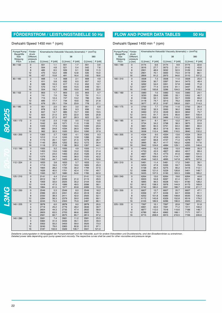
FÖRDERSTROM / LEISTUNGSTABELLE FLOW AND POWER DATA TABLES50 Hz 50 Hz
80 / 132 048
1216
551504485470457
1.14.88.5
12.215.8
551521509499491
1.75.49.1
12.816.4
551542538535532
3.97.6
11.315.018.6
80 / 160 048
1216
668611588570554
1.45.8
10.314.719.2
668632617605596
2.16.5
11.015.519.9
668657652648645
4.89.2
13.718.122.6
90 / 152 048
1216
803741715695679
1.77.0
12.417.723.1
803764747734724
2.57.9
13.218.623.9
803791786782778
5.711.116.421.827.1
90 / 180 048
1216
951878847823804
2.08.3
14.721.027.3
951904885870857
3.09.3
15.722.028.3
951936930926922
6.813.119.525.832.1
100 / 172 048
1216
112210421009
983962
2.39.8
17.324.832.3
11221071105010341020
3.511.018.526.033.4
11221106109910941090
8.015.523.030.437.9
100 / 200 048
1216
13051212117311431118
2.711.420.128.837.5
13051245122112021186
4.112.821.530.238.9
13051286127812721267
9.318.026.735.444.1
112 / 190 048
1216
15551453141113791352
3.213.624.034.344.7
15551490146314431425
4.915.225.636.046.3
15551535152615201514
11.121.431.842.252.6
112 / 224 048
1216
18331713166416261593
3.816.028.240.552.7
18331757172517011680
5.718.030.242.454.6
18331809179917911785
13.125.337.549.762.0
125 / 210 048
1216
21412012195919181884
4.418.733.047.361.5
21412059202519991977
21.035.249.563.8
21412115210420962089
15.329.543.858.172.3
125 / 250 048
1216
25492396233222842243
5.322.339.356.373.3
25492451241123792353
8.025.042.059.075.9
25492518250524952487
18.235.252.169.186.1
140 / 225 048
1216
28782719265426032561
6.025.244.363.582.7
28782776273527032675
9.028.247.466.685.7
28782846283228222814
20.539.758.978.197.2
140 / 280 048
1216
35813384330232403187
7.431.355.279.0
102.9
35813455340333633329
11.235.159.082.8
106.7
35813541352535123501
25.549.473.397.1
121.0
Pumpe/ PumpBaugröße
SizeSteigung
Pitch
Kinematische Viskosität / Viscosity (kinematic) (mm /s)
Detailierte Leistungsdaten in Abhängigkeit der Pumpendrehzahl und der Viskosität, auch für andere Viskositäten und Druckbereiche, sind den Einzelkennlinien zu entnehmen.Detailed power data depending upon pump speed and viscosity. The respective curves shall be used for other viscosities and pressure range.
160 / 190 048
1216
31743016295129012859
6.627.748.970.191.2
31743073303230002973
9.931.152.373.494.6
31743142312931193110
22.643.864.986.1
107.2
160 / 210 048
1216
35083334326232073160
7.330.754.077.4
100.8
35083397335133163286
11.034.457.881.1
104.5
35083473345834473438
25.048.471.895.2
118.5
180 / 160 048
1216
33833230316631183077
7.029.652.174.797.2
33833285324432133187
10.633.155.778.2
100.8
33833352333933293321
24.146.769.291.8
114.3
180 / 175 048
1216
37003532346334103365
7.732.357.081.7
106.3
37003593354935153486
11.636.260.985.6
110.2
37003666365236413632
26.451.075.7
100.4125.0
180 / 185 048
1216
39113734366136053558
8.134.260.386.3
112.4
39113798375137163685
12.238.364.490.5
116.5
39113875386138493840
27.953.980.0
106.1132.2
180 / 205 048
1216
43344138405739953942
9.037.966.895.7
124.6
43344209415741174084
13.642.571.4
100.2129.1
43344294427842654255
30.959.888.7
117.6146.4
200 / 190 048
1216
49594753466746014546
10.343.376.4
109.5142.5
49594827477347314695
15.548.681.6
114.7147.8
49594917490048874876
35.368.4
101.5134.5167.6
200 / 210 048
1216
54815253515850865025
11.447.984.4
121.0157.5
54815335527552295190
17.253.790.2
126.8163.3
54815435541654015389
39.175.6
112.1148.7185.2
200 / 240 048
1216
62646003589558125742
13.054.896.5
138.3180.0
62646097602859765931
19.661.4
103.1144.9186.7
62646211619061736159
44.686.4
128.2169.9211.7
225 / 200 048
1216
66076356625261726105
13.757.7
101.8145.8189.9
66076446638063296286
20.764.7
108.8152.8196.9
66076556653565196505
47.191.1
135.2179.2223.2
225 / 220 048
1216
72676991687767896715
15.163.5
112.0160.4208.9
72677091701869626915
22.871.2
119.6168.1216.5
72677211718871717156
51.8100.2148.7197.1245.6
Pumpe/PumpBaugröße
SizeSteigung
Pitch
Kinematische Viskosität / Viscosity (kinematic) (mm /s)Förder-druck
Different.pressurep [bar]
Drehzahl / Speed 1450 min -1 (rpm)
Förder-druck
Different.pressurep [bar]
Drehzahl / Speed 1450 min -1 (rpm)
12
Q [l/min] P [kW]
38
Q [l/min] P [kW]
380
Q [l/min] P [kW]
12
Q [l/min] P [kW]
38
Q [l/min] P [kW]
380
Q [l/min] P [kW]
L3N
G20
-70
80-2
25

LEISTRITZ PUMPEN GMBH
23
FÖRDERSTROM / LEISTUNGSTABELLE FLOW AND POWER DATA TABLES60 Hz 60 Hz
80 / 132 048
1216
665618599584571
1.56.0
10.414.819.3
665635623613605
2.36.8
11.215.620.1
665656652649646
5.39.7
14.118.623.0
80 / 160 048
1216
806750726708693
1.97.2
12.618.023.4
806770755744734
2.88.2
13.618.924.3
806795790787783
6.411.817.122.527.9
90 / 152 048
1216
970907881862845
2.28.7
15.221.628.1
970930913901890
3.49.8
16.322.829.2
970957952948944
7.714.220.627.133.5
90 / 180 048
1216
11481074104410201000
2.710.318.025.633.3
11481101108110671054
4.011.719.327.034.6
11481133112711221118
9.116.824.432.139.7
112 / 224 048
1216
22132093204320051973
5.119.934.649.464.1
22132136210420802060
7.722.537.252.066.7
22132189217821712164
17.632.347.161.876.6
125 / 210 048
1216
25842455240223612327
6.023.240.457.674.9
25842502246824422420
26.243.560.777.9
25842558254725392532
20.537.755.072.289.4
125 / 250 048
1216
30762923286028112770
7.127.648.168.689.1
30762978293829072881
10.731.251.772.292.8
30763045303230233014
24.444.965.485.9
106.4
140 / 225 048
1216
34733315324931993156
8.031.254.377.5
100.6
34733372333032983271
12.135.358.481.6
104.7
34733441342834183409
27.650.773.997.0
120.2
140 / 280 048
1216
43224125404339813928
10.038.867.696.4
125.2
43224196414441044070
15.143.972.7
101.5130.3
43224282426642534242
34.363.191.9
120.7149.5
Pumpe/PumpBaugröße
SizeSteigung
Pitch
Kinematische Viskosität / Viscosity (kinematic) (mm /s)
Detailierte Leistungsdaten in Abhängigkeit der Pumpendrehzahl und der Viskosität, auch für andere Viskositäten und Druckbereiche, sind den Einzelkennlinien zu entnehmen.Detailed power data depending upon pump speed and viscosity. The respective curves shall be used for other viscosities and pressure range.
160 / 190 048
1216
38303673360835583516
8.834.459.985.5
111.0
38303730368836563630
13.438.964.490.0
115.5
38303799378537753767
30.455.981.5
107.0132.5
160 / 210 048
1216
42344060398839333886
9.838.066.294.4
122.7
42344123407740414012
14.843.071.299.4
127.7
42344199418441734163
33.661.890.0
118.3146.5
180 / 160 048
1216
40823929386638183777
9.436.663.991.1
118.3
40823985394439133887
14.241.468.795.9
123.1
40824052403940294021
32.459.686.8
114.0141.3
180 / 175 048
1216
44654298422941754131
10.340.169.899.6
129.4
44654358431442804252
15.645.375.1
104.9134.6
44654431441744074398
35.465.295.0
124.7154.5
180 / 185 048
1216
47204543447044144367
10.942.473.8
105.3136.8
47204607456145254495
16.547.979.4
110.9142.3
47204685467046584649
37.468.9
100.4131.9163.3
180 / 205 048
1216
52315035495448914839
12.147.081.8
116.7151.6
52315105505450144980
18.253.188.0
122.8157.7
52315191517551625151
41.576.4
111.2146.1181.0
200 / 190 048
1216
59855779569356275572
13.853.793.6
133.5173.4
59855853579957575721
20.960.8
100.7140.6180.5
59855943592659135902
47.587.4
127.3167.2207.1
200 / 210 048
1216
66156387629262206159
15.359.4
103.5147.6191.7
66156469640963636324
23.167.2
111.3155.4199.5
66156569655065356523
52.596.6
140.7184.8228.9
200 / 240 048
1216
75607299719171087038
17.567.9
118.3168.7219.1
75607393732472727227
26.476.8
127.2177.6228.0
75607507748674697455
60.0110.4160.8211.2261.6
225 / 200 048
1216
79737723761975397472
18.471.6
124.7177.9231.0
79737813774776967653
27.881.0
134.1187.3240.4
79737923790278867872
63.3116.4169.6222.7275.9
225 / 220 048
1216
87718495838082938219
20.378.7
137.2195.7254.1
87718595852284668418
30.689.0
147.5206.0264.5
87718715869286748659
69.6128.1186.5245.0303.5
Pumpe/PumpBaugröße
SizeSteigung
Pitch
Kinematische Viskosität / Viscosity (kinematic) (mm /s)
100 / 172 048
1216
13541274124112161194
3.112.221.230.239.2
13541303128212661252
4.713.822.831.840.8
13541338133213261322
10.719.828.837.846.9
100 / 200 048
1216
15751482144314131388
3.614.124.635.145.6
15751515149114721456
5.516.026.537.047.5
15751556154815421537
12.523.033.544.054.5
112 / 190 048
1216
18771775173317011673
4.316.829.441.954.4
18771812178517641747
6.519.131.644.156.6
18771856184818411836
14.927.439.952.464.9
Förder-druck
Different.pressurep [bar]
Drehzahl / Speed 1750 min -1 (rpm)
Förder-druck
Different.pressurep [bar]
Drehzahl / Speed 1750 min -1 (rpm)
12
Q [l/min] P [kW]
38
Q [l/min] P [kW]
380
Q [l/min] P [kW]
12
Q [l/min] P [kW]
38
Q [l/min] P [kW]
380
Q [l/min] P [kW]
L3N
G20
-70
80-2
25

Das Leistritz-Schraubenspindel-Pumpen-ProgrammThe Leistritz Screw Pump Program
L3M
F/L3
HF
L2N
GL3
NG
L4N
G/L
4MG
L5N
G L
3MG
/L3H
G
LEISTRITZ PUMPEN GMBHPostfach 30 41D-90014 NürnbergMarkgrafenstraße 29-39D-90459 NürnbergTel.: +49 9 11 / 43 06 - 0Fax: +49 9 11 / 43 06 - 490E-Mail: [email protected]
LEISTRITZ PUMPEN GMBHP.O. Box 30 41D-90014 NurembergMarkgrafenstrasse 29-39D-90459 NurembergPhone.: +49 9 11 / 43 06 - 0Fax: +49 9 11 / 43 06 - 490E-Mail: [email protected]
Ihr Leistritz Partner/Your Leistritz partner:
www.leistritz.comwww.leistritz.com
L3N-Reihe: L3N-Series:
für schmierende und niederviskose for low viscosity fluids withMedien im Niederdruckbereich good lubricity, for low pres-bis 16 bar (232 psi). sure range up to 16 bar (232 psi).
L4-Reihe: L4-Series:
für aggressive, abrasive, nicht for corrosive, abrasive andschmierende und niedervis- high or low viscosity fluids withkose Medien im Mitteldruck- poor lubricity, for pressu-bereich bis 40 bar (580 psi). re ranges up to 40 bar (580 psi).
L5-Reihe: L5-Series:
für schmierende, nicht aggres- for lubricating, non corrosivesive und leicht abrasive and slightly abrasive fluids,Medien im Niederdruck- with low pressure rangesbereich bis 10 bar (150 psi). up to 10 bar (150 psi).
L3H-Reihe: L3H-Series:
für schmierende, niedrig- hoch- for high or low viscosity fluids withbis viskose Medien im Hochdruck- good lubricity, for high pressurebereich bis 160 bar (2320 psi). ranges up to 160 bar (2320 psi).
1.2
- 14
d-e
05/
04 3
’ tü
L3M-Reihe: L3M-Series:
für schmierende, niedrig- bis hoch- for high or low viscosity fluids withviskose Medien im Mitteldruckbereich good lubricity, for medium pressurebis 100 bar (1450 psi). ranges up to 100 bar (1450 psi).
L2-Reihe: L2-Series:
für die Förderung von bedingt aggres- for light abrasive and corrosive,siven, leicht abrasiven, schlecht schmie- high or low viscosity fluidsrenden und hochviskosen Medien, im with poor lubricity, for pressure Niederdruckbereich bis 16 bar (232 psi). range up to 16 bar (232 psi).