screw jack
TRANSCRIPT

-

Product: Screw Jack
INTRODUCTION PROJECT MOTIVATION:
With the increasing levels of technology, the efforts being put to produce any kind
of work has been continuously decreasing. The efforts required in achieving the
desired output can be effectively and economically be decreased by the
implementation of better designs. Power screws are used to convert rotary motion
into translatory motion. A screw jack is an example of a power screw in which a
small force applied in a horizontal plane is used to raise or lower a large load. The
principle on which it works is similar to that of an inclined plane. The mechanical
advantage of a screw jack is the ratio of the load applied to the effort applied. The
screw jack is operated by turning a lead screw. The height of the jack is adjusted by
turning a lead screw and this adjustment can be done either manually
Most people are familiar with the basic car jack (manually operated) that is still
included as standard equipment with most new cars. In the repair and
maintenance of automobiles (car), it is often necessary to raise an automobile to
change a tire or access the underside of the automobile. Accordingly, a variety of
car jacks have been developed for lifting an automobile from a ground Surface. A
typically manually operated (basic model) is taken as a Product for project in the
course DESIGN FOR MANUFACTURING AND ASSEMBLY LAB to know the entire
process of product design.

THEORY OF MANUFACTURABILY AND ASSEMBLY
A screw jack is a portable device consisting of a screw mechanism used to raise or
lower the load. The principle on which the screw jack works is similar to that of an
inclined plane. There are mainly two types of jacks-hydraulic and mechanical. A
hydraulic jack consists of a cylinder and piston mechanism. The movement of the
piston rod is used to raise or lower the load. Mechanical jacks can be either hand
operated or power driven.
Jacks are used frequently in raising cars so that a tire can be changed. A screw
jack is commonly used with cars but is also used in many other ways, including
industrial machinery and even airplanes. They can be short, tall, fat, or thin
depending on the amount of pressure they will be under and the space that
they need to fit into. The jack is made out of various types of metal, but the
screw itself is generally made out of lead.
While screw jacks are designed purposely for raising and lowering loads, they
are not ideal for side loads, although some can withstand side loads depending
on the diameter and size of the lifting screw. Shock loads should also be
avoided or minimized. Some screw jacks are built with anti-backlash. The anti-
backlash device moderates the axial backlash in the lifting screw and nut
assembly to a regulated minimum.
A large amount of heat is generated in the screw jack and long lifts can cause
serious overheating. To retain the efficiency of the screw jack, it must be used
under ambient temperatures, otherwise lubricants must be applied. There are
oil lubricants intended to enhance the equipment‟s capabilities. Apart from
proper maintenance, to optimize the capability and usefulness of a screw jack
it is imperative to employ it according to its design and manufacturers instruction.
Ensure that you follow the speed, load capacity, temperature recommendation
and other relevant factors for application

Types:Screw Jacks are of mainly two types.
1. Mechanical
2. Hydraulic.
They vary in size depending on the load that they are used to lift
Mechanical Jacks:
A mechanical jack is a device which lifts heavy equipment. The most common form
is a car jack, floor jack or garage jack which lifts vehicles so that maintenance can
be performed. Car jacks usually use mechanical advantage to allow a human to lift
a vehicle by manual force alone. More powerful jacks use hydraulic power to
provide more lift over greater distances. Mechanical jacks are usually rated for
maximum lifting capacity. There are two types of mechanical jacks:
● Scissor Jacks
● Bottle (cylindrical) Jacks
Scissor Jacks:Scissors jacks are also mechanical and have been in use at least since
the 1930s.A scissor jack is a device constructed with a cross-hatch mechanism,
much like a scissor, to lift up a vehicle for repair or storage. It typically works in just
a vertical manner. The jack opens and folds closed, applying pressure to the
bottom supports along the crossed pattern to move the lift. When closed, they
have a diamond shape. Scissor jacks are simple mechanisms used to drive large
loads short distances. The power screw design of a common scissor jack reduces
the amount of force required by the user to drive the mechanism. Most scissor
jacks are similar in design, consisting of four main members driven by a power
screw.A scissor jack is operated simply by turning a small crank that is inserted into
one end of the scissor jack. This crank is usually "Z" shaped. The end fits into a ring
hole mounted on the end of the screw, which is the object of force on the scissor
jack. When this crank is turned, the screw turns, and this raises the jack. The screw
acts like a gear mechanism. It has teeth (the screw thread), which turn and move

the two arms, producing work. Just by turning this screw thread, the scissor jack
can lift a vehicle that is several thousand pounds.
Construction:
A scissor jack has four main pieces of metal and two base ends. The four metal
pieces are all connected at the corners with a bolt that allows the corners to
swivel. A screw thread runs across this assembly and through the corners. As the
screw thread is turned, the jack arms travel across it and collapse or come
together, forming a straight line when closed. Then, moving back the other way,
they raise and come together. When opened, the four metal arms contract
together, coming together at the middle, raising the jack. When closed, the arms
spread back apart and the jack closes or flattens out again.
Design and Lift:
A scissor jack uses a simple theory of gears to get its power. As the screw section is
turned, two ends of the jack move closer together. Because the gears of the screw
are pushing up the arms, the amount of force being applied is multiplied. It takes a
very small amount of force to turn the crank handle, yet that action causes the
brace arms to slide across and together. As this happens the arms extend upward.
The car's gravitational weight is not enough to prevent the jack from opening or to
stop the screw from turning, since it is not applying force directly to it. If you were
to put pressure directly on the crank, or lean your weight against the crank, the

person would not be able to turn it, even though your weight is a small percentage
of the cars.
Bottle (cylindrical) Jacks:
Bottle screws may operate by either
(i) Rotating the screw when the nut is fixed; or
(ii)Rotating the nut and preventing rotation of the screw.
Bottle jacks mainly consist of a screw, a nut, thrust bearings, and a body. A
stationary platform is attached to the top of the screw. This platform acts as a
support for the load and also assists it in lifting or lowering of the load. These jacks
are sturdier than the scissor jacks and can lift heavier loads.

HYDRAULIC JACKS:
Hydraulic jacks are typically used for shop work, rather than as an emergency jack
to be carried with the vehicle. Use of jacks not designed for a specific vehicle
requires more than the usual care in selecting ground conditions, the jacking point
on the vehicle, and to ensure stability when the jack is extended. Hydraulic jacks
are often used to lift elevators in low and medium rise buildings. A hydraulic jack
uses a fluid, which is incompressible, that is forced into a cylinder by a pump
plunger. Oil is used since it is self lubricating and stable. When the plunger pulls
back, it draws oil out of the reservoir through a suction check valve into the pump
chamber. When the plunger moves forward, it pushes the oil through a discharge
check valve into the cylinder. The suction valve ball is within the chamber and
opens with each draw of the plunger. The discharge valve ball is outside the
chamber and opens when the oil is pushed into the cylinder. At this point the
suction ball within the chamber is forced shut and oil pressure builds in the
cylinder.

In a bottle jack the piston is vertical and directly supports a bearing pad that
contacts the object being lifted. With a single action piston the lift is somewhat
less than twice the collapsed height of the jack, making it suitable only for vehicles
with a relatively high clearance. For lifting structures such as houses the hydraulic
interconnection of multiple vertical jacks through valves enables the even
distribution of forces while enabling close control of the lift.
In a floor jack a horizontal piston pushes on the short end of a bellcrank , with the
long arm providing the vertical motion to a lifting pad, kept horizontal with a
horizontal linkage. Floor jacks usually include castors and wheels, allowing
compensation for the arc taken by the lifting pad. This mechanism provide a low
profile when collapsed, for easy maneuvering underneath the vehicle, while
allowing considerable extension
COMPONENTS AND SUB-ASSEMBLIES , PROCESS PLANS
It consists of a screw of a screw and a nut. The nut is fixed in a cast iron frame and
remains stationary. The rotation of the nut inside the frame is prevented by
pressing s setscrew against it. The screw is rotated in the nut by means of a
handle, which passes through a hole In the head of the screw. The head carries a
cup, which supports the load and remains stationary while the screw is being
rotated. There is collar friction at the annular contacting surface between the cup
and the head of the screw. A washer is fixed to the other end of the screw inside
the frame, which prevents the screw to be completely turned out of the nut
Features:
All jacks have safety features to protect the user from accidental injury. Wide
bases help to stabilize a jack and prevent tilting or sinking into soft soil. Most car
jacks also come equipped with their own handle or cranking mechanism, but
alternately many of these also will accept the flat end of a tire tool to jack up a
vehicle. When in the extended position, jacks will have a stop point that prevents
the user from overextending the jack beyond its rated capabilities. When in the
contracted position, jacks that are provided by the manufacturer will have a
storage area specially formed or designed for the jack to rest in when not in use
Benefits: Equipping motorists with car jacks has provided many benefits to those
who are on the road. Most importantly, jacks have equipped drivers with the
ability to change a tire in an emergency situation without having to call for
assistance, which can save service fees and potential towing fees as well. Car jacks
also provide the home auto enthusiast with a tool to use in maintenance of their
own vehicle with the simpler tasks such as changing brake pads, oil and belts.
When used appropriately with safety in mind, car jacks are an essential resource
for anyone owning or operating a motorized vehicle.

Bill of Materials:
S.NO COMPONENTS QUANTITY MATERIAL
1 FRAME 1 GREY CAST IRON FG200 (IS:210-1993)
2 SCREW 1 STEEL30C8 (IS:1570-1978)
3 NUT 1 PHOSPHOR BRONZE GRADE- 1(IS:28-1975)
4 HANDLE 1 PLAIN CARBON STEEL30C8(IS:1570-1978)
5 CUP 1 GREY CAST IRON FG200 (IS:210-1993
6 SET SCREW 1 COMMERCIAL STEEL
7 WASHER 1 COMMERCIAL STEEL

1. FRAME
• FRAME SIZE: Most of the times frame is conical in shape and hollow internally to
accommodate a nut & screw assembly. The hollow conical shape insures a safe & complete
resting of a jack on ground. If it is provided with legs like structure , it quite possible that in
case of uneven distribution load may fail down because all legs will not touch ground.
• FORCE ANALYSIS: The force by a load is directed by a cup to screw then is directed by cup to
screw then to threads of screw to nut then to frame so it is always compressive in nature.
• MANUFACTURING PROCESS: The complex shape of frame leads us to use a ’Casting’ process
for manufacturing.
For all this purpose we need to select a cast iron as material for frame. We select a FG200
as material for frame such as it contains carbon precipitates as “graphite flakes” as graphite is
soft in nature it improves its ability to resist a compressive load.
● FG200 = Graphite flakes Gray cast iron with ultimate tensile strength of 200N/mm2
*** Same dimensions are used to design the product in CATIA V
Source for image: https://www.behance.net/gallery/7195805/Screw-Jack

2. SCREW:
• Screw size: The screw has a thread designed to withstand an enormous amount of pressure. This is
due to the fact that it is generally holding up heavy objects for an extended amount of time. Once up,
they normally self lock so that they won't fall if the operator lets go, and they hold up well to the wear
of repeated use. If they are made with a ball nut, they will last longer because there is less friction
created with this type of jack. However, they will not self lock. This can be dangerous and handled
carefully. It can be around 22 to 100mm diameter for square power screws & 24 to 100mm for
trapezoidal power screws.
• Thread profile – The screw or power screw thread is always a square type because it has more
efficiency than trapezoidal threads and there is no radial thrust on screw i.e. no Bursting Pressure, so
motion is uniform.
• Square threads usually turned on lathes using single point cutting tool. It leads us to use free cutting
steel. Square threads are weak in roots. Wear of thread surface lead us to use “Unalloyed free cutting
steel”.
•We select “25C12S14 UNALLOED FREE CUTTING STEEL” .It indicates - 025% carbon, 1.2%
manganese, 0.14%sulphur
•It has tensile strength of 560N/mm2 with 10% elongation. Sulphur gives resistance to wear & 0.25%
carbon gives it sufficient strength to compensate weakness in roots, also easy in cutting due to
manganese
** Same dimensions are used to design the product in CATIA v6

3.NUT:
• As we know there always a relative motion between screw and nut, which cause a friction.
The friction causes wear if some material is used for screw & nut it will wears both
components. So one out of two has to be softer than other so as to ease of replacement. The
size & shape of screw is costlier than nut, so generally we use softer material for nut than
screw.
• Phosphor bronze is ideal material for nut which is a copper alloy having 0.2% phospher
which increases tensile strength. Ultimate tensile strength for this is 190mpa and coefficient of
friction is 0.1
Bearing pressure is 10mpa.
• Advantages of phosphor bronze are,
*Good corrosion resistance.
* Low coefficient of friction
* Higher tensile strength than copper brass.
*** Same dimensions are used to design the product in CATIA V6
*** Source for image : https://www.behance.net/gallery/7195805/Screw-Jack

4. HANDLE :
•Handle is subjected ti bending moments.
• So plain carbon steel with 0.3%carbon i.e. 30C8 can be selected.
• Yield strength in tension is 400mpa
5. SETSCREW:
• Purpose of set screw is to resist motion of nut with screw.
• It can be of commercial steel.
6. WASHER:
• Washer is to provide uniform force of tightening nut over screw force by enlarging area
under actions of force. We can use commercial steel.
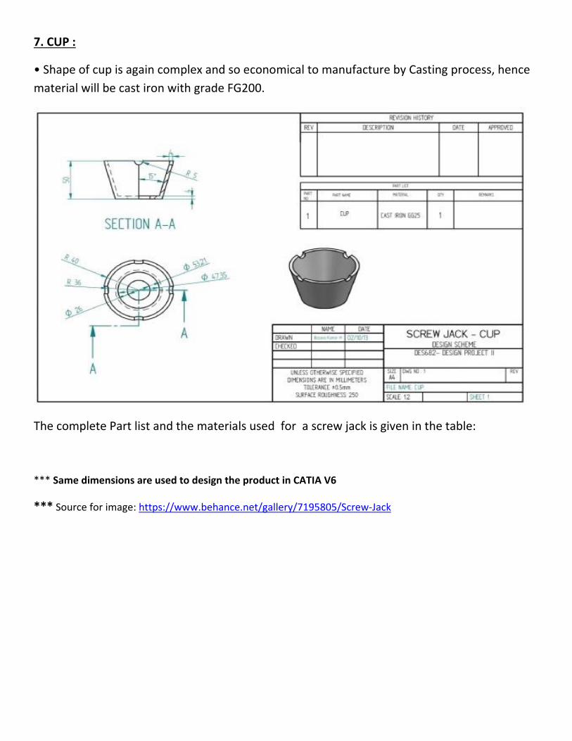
7. CUP :
• Shape of cup is again complex and so economical to manufacture by Casting process, hence
material will be cast iron with grade FG200.
The complete Part list and the materials used for a screw jack is given in the table:
*** Same dimensions are used to design the product in CATIA V6
*** Source for image: https://www.behance.net/gallery/7195805/Screw-Jack

MANUFACTURABILITY AND ASSEMBLY OF THE PRODUCT
The following is the assembly of the screw jack consisting of only five parts .It doesn’t have
Set-screw and washer.
The 3D Solid model of the Same product is designed in Catia V6 with the same Dimensions
Although a jack is simple and widely used device, the use of any lifting device is subject to
certain hazards. In screw jack applications, the hazards are dropping, tipping or slipping of
machines or their parts during the operation. These hazards may result in serious accidents.
The main reasons of such accidents are as follows:
• Load is improperly secured on jack.
•The screw jack is overloaded.
• Center of gravity is off center with axis of jack.
•Jack is not placed on hard & level surface.
• Using for other purpose instead of using it for which it is designed.

Merits of Screw jack:
•Can be used to lift a heavy load against gravity.
•Load can be kept in lifted position.
• Due to leverage obtained by handle force required to raise load is very less & can be applied
manually also
Demerits of screw jack:
•Chances of dropping of load
• Tipping or slipping of load.
• This failure is not “SAFE FAIL”& can cause serious accidents.
Proper size, strength and stability are the essential requirements for the design of the screw
jack from safety considerations
Operational Considerations of a screw jack:
• Maintain low surface contact pressure: Increasing the screw size and nut size will reduce
thread contact pressure for the same working load. The higher the unit pressure and the
higher the surface speed, the more rapid the wear will be.
• Maintain low surface speed: Increasing the screw head will reduce the surface speed for the
same linear speed.
• Keep the mating surfaces well lubricated: The better the lubrication, the longer is the service
life. Grease fittings or other lubrication means must be provided for the power screw and nut.
• Keep the mating surfaces clean: Dirt can easily embed itself in the soft nut material. It will
act as a file and abrade the mating screw surface. The soft nut material backs away during
contact leaving the hard dirt particles to scrap away the mating screw material.
• Keep heat away: When the mating surfaces heat up, they become much softer and are more
easily worn away. Means to remove the heat such as limited duty cycles or heat sinks must be
provided so that rapid wear of over-heated materials can be avoided

IMPROVEMENTS MADE: MOTARIZED SCREW JACK
The motorized screw jack has been developed to cater to the needs of small and medium
automobile garages, which are normally man powered with minimum skilled labor. In most of
the garages the vehicles are lifted by using screw jack. This needs high man power and skilled
labour.
In order to avoid all such disadvantages, the motorized jack has been designed in such a way
that it can be used to lift the vehicle very smoothly without any impact force. The operation is
made simple so that even unskilled labour can use it with ease.
The d.c motor is coupled with the screw jack by gear arrangement. The screw jack shaft‟s
rotation depends upon the rotation of D.C motor. This is a simple type of automation project.
This is an era of automation where it is broadly defined as replacement of manual effort by
mechanical power in all degrees of automation. The operation remains to be an essential part
of the system although with changing demands on physical input, the degree of mechanization
is increased
Need for automation:
•To achieve mass production
•To reduce man power
•To reduce the work load
• To reduce the production cost
•To reduce the production time
•To reduce the material handling
•To reduce the fatigue of workers
•To achieve good product quality
•Less Maintenance

Working Principle:
The lead-acid battery is used to drive the D.C motor. The D.Cmotor shaft is connected to the
spur gear. If power is given to the D.C motor, it will run so that the spur gear also runs to slow
down the speed of the D.C motor.
The screw jack moves the screw upward, so that the vehicle lifts from ground.The vehicle is
lifted by using the lifting platform at the top of the screw jack. The motor draws power supply
from the battery. The lifting and uplifting is done by changing the battery supply to the motor.
Advantages:
1. The loaded light vehicles can be easily lifted.
2. Checking and cleaning are easy, because the main parts are screwed.
3. Handling is easy
4. No Manual power required.
5. Easy to Repair.
6. Replacement of parts are easy
Disadvantages:
1. Cost of the equipment is high when compared to ordinary hand jack.
2. Care must be taken for the handling the equipment such as proper wiring connection,
battery charging checkup, etc.

CONCLUSION
Screw Jacks are the ideal product to push, pull, lift, lower and position loads of anything from a
couple of kilograms to hundreds of tonnes. The need has long existed for an improved
portable jack for automotive vehicles. It is highly desirable that a jack become available that
can be operated alternatively from inside the vehicle or from a location of safety off the road
on which the vehicle is located. Such a jack should desirably be light enough and be compact
enough so that it can be stored in an automobile trunk, can be lifted up and carried by most
adults to its position of use, and yet be capable of lifting a wheel of a 4,000-5,000 pound
vehicle off the ground. Further, it should be stable and easily controllable by a switch so that
jacking can be done from a position of safety. It should be easily movable either to a position
underneath the axle of the vehicle or some other reinforced support surface designed to be
engaged by a jack
Thus, the product has been developed considering all the above requirements. This particular
design of the motorized screw jack will prove to be beneficial in lifting and lowering of loads
