sct weight transmitter - aaaweigh.com
TRANSCRIPT
SCT Weight Transmitter30 Series
Installation & Operator’s Manual
159585


i
Technical training seminars are available through Rice Lake Weighing Systems.
Course descriptions and dates can be viewed at www.ricelake.com/trainingor obtained by calling 715-234-9171 and asking for the training department.
Contents
1.0 Introduction............................................................................... 11.1 Safety. . . . . . . . . . . . . . . . . . . . . . . . . . . . . . . . . . . . . . . . . . . . . 11.2 Specifications . . . . . . . . . . . . . . . . . . . . . . . . . . . . . . . . . . . . . . 41.3 Electrical Connections . . . . . . . . . . . . . . . . . . . . . . . . . . . . . . . 61.4 Analog Output Type Selection . . . . . . . . . . . . . . . . . . . . . . . . . 71.5 Instrument Commissioning. . . . . . . . . . . . . . . . . . . . . . . . . . . . 8
2.0 Calibration ................................................................................ 92.1 Real Calibration (With Sample Weights) . . . . . . . . . . . . . . . . . 92.2 Theoretical Calibration . . . . . . . . . . . . . . . . . . . . . . . . . . . . . . 102.3 Digital Filtering . . . . . . . . . . . . . . . . . . . . . . . . . . . . . . . . . . . . 10
3.0 RS-485 Serial Connection ...................................................... 113.1 Continuous One Way Transmission Protocol . . . . . . . . . . . . 113.2 Modbus-RTU Protocol . . . . . . . . . . . . . . . . . . . . . . . . . . . . . . 113.3 Alarms . . . . . . . . . . . . . . . . . . . . . . . . . . . . . . . . . . . . . . . . . . . 13
4.0 Reserved for the Installer ....................................................... 144.1 Restoring Factory Values . . . . . . . . . . . . . . . . . . . . . . . . . . . . 144.2 Calibration and RS-485 Port Setting Access Limitation . . . . 14
© Rice Lake Weighing Systems. All rights reserved. Printed in the United States of America. Specifications subject to change without notice.
Rice Lake Weighing Systems is an ISO 9001 registered company.December 05, 2013

ii SCT-30 Weight Transmitter Manual
Rice Lake continually offers web-based video training on a growing selection
of product-related topics at no cost. Visit www.ricelake.com/webinars.

Introduction 1
1.0 Introduction
1.1 Safety1.1.1 Safety Symbol Definitions:
Indicates a potentially hazardous situation that, if not avoided, could result in death or serious injury, and includes hazards that are exposed when guards are removed.Indicates information about procedures that, if not observed, could result in damage to equipment or corruption to and loss of data.
1.1.2 Safety Precautions
Failure to heed may result in serious injury or death.Do not operate or work on this equipment unless you have read and understand the instructions and warnings in this manual. Contact any Rice Lake Weighing System dealer for replacement manuals. Proper care is your responsibility.Risk of electrical shock. No user serviceable parts. Refer to
qualified service personnel for service. The unit has no power switch. To completely remove D/C power from the unit,disconnect the D/C power cable from the main socket.DO NOT allow minors (children) or inexperienced persons to operate this unit.DO NOT operate without all shields and guards in place.DO NOT use for purposes other then weighing applications.DO NOT place fingers into slots or possible pinch points.DO NOT use this product if any of the components are cracked.DO NOT make alterations or modifications to the unit.DO NOT remove or obscure warning labels.DO NOT use near water.
WARNING
Important
WARNING

2 SCT-30 Weight Transmitter Manual
1.1.3 Equipment RecommendationsFailure to follow the installation recommendations will be considered a misuse of the equipment.
To Avoid Equipment Damage• Keep away from heat sources and direct sunlight.• Protect the instrument from rain.• Do not wash, dip in water or spill liquid on the instrument.• Do not use solvents to clean the instrument.• Do not install in areas subject to explosion hazard.
1.1.4 Correct Installation of Weighing Instruments• The terminals indicated on the instrument’s wiring diagram to be connected to
ground must have the same potential as the scale structure (ground). If you areunable to ensure this condition, connect a ground wire between the instrumentand the scale structure.
• The load cell cable must be run separately to the instrument input and not share aconduit with other cables. A shielded connection must be continuous without asplice.
• Use “RC” filters (quench-arcs) on the instrument-driven solenoid valve andremote control switch coils.
• Avoid electrical noise in the instrument panel; if inevitable, use special filters orsheet metal partitions to isolate.
• The panel installer must provide electrical protection for the instruments (fuses,door lock switch, etc.).
• It is advisable to leave equipment always switched on to prevent the formation ofcondensation.
• Maximum cable lengths:- RS-485: 1000 meters with AWG24, shielded and twisted cables
- Analog current output: up to 500 meters with 0.5 mm2 cable
- Analog current output: up to 300 meters with 0.5 mm2 cable
1.1.5 Correct Installation of the Load CellsInstalling Load Cells: The load cells must be placed on rigid, stable structures within .5% of plumb andlevel. It is important to use mounting modules for load cells to compensate formisalignment of the support surfaces.
Protection Of The Load Cell Cable: Use waterproof sheaths and joints in order to protect the cables of the load cells.
Mechanical Restraints (pipes, etc.): When pipes are present, we recommend the use of hoses, flexible couplings andrubber skirted joints. In case of rigid conduit and pipes, place the pipe support oranchor bracket as far as possible from the weighed structure (at a distance at least 40times the diameter of the pipe).
Important
Introduction 3
Connecting Several Cells in Parallel: Connect several load cells in parallel by using, if necessary, a watertight junction boxwith a terminal box. The load cell connection extension cables must be shielded,placed individually into their piping or conduit, and laid as far as possible from thepower cables (in case of 4-wire connections, use cables with 4 x 1 sq.mm minimumcross-section).
Welding: Avoid welding with the load cells already installed. If this cannot be avoided, placethe welder ground clamp close to the required welding point to prevent sendingcurrent through the load cell body.
Windy Conditions - Shocks - Vibrations: The use of weigh modules is strongly recommended for all load cells to compensatefor misalignment of the support surfaces. The system designer must ensure that thescale is protected against lateral shifting and tipping relating to shocks and vibration,windy conditions, seismic conditions and stability of the support structure.
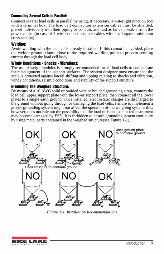
Grounding The Weighed Structure: By means of a 10 AWG solid or braided wire or braided grounding strap, connect theload cell upper support plate with the lower support plate, then connect all the lowerplates to a single earth ground. Once installed, electrostatic charges are discharged tothe ground without going through or damaging the load cells. Failure to implement aproper grounding system might not affect the operation of the weighing system; this,however, does not rule out the possibility that the load cells and connected instrumentmay become damaged by ESD. It is forbidden to ensure grounding system continuityby using metal parts contained in the weighed structure(see Figure 1-1).
Figure 1-1. Installation Recommendations
Uses ground plate to continue ground.
Uses structure to continue ground.

4 SCT-30 Weight Transmitter Manual
1.1.6 Load Cell TestingLoad Cell Resistance Measurement (Use a Digital Multimeter):
• Disconnect the load cells from the instrument and check that there is no moisturein the load cell junction box caused by condensation or water infiltration. If so,drain the system or replace it if necessary.
• The value between the positive signal wire and the negative signal wire must beequal or similar to the one indicated in the load cell data sheet (output resistance).
• The value between the positive excitation wire and the negative excitation wiremust be equal or similar to the one indicated in the load cell data sheet (inputresistance).
• The insulation value between the shield and any other load cell wire, andbetween any other load cell wire and the body of the load cell, must be higherthan 20 Mohm (mega ohms).
Load Cell Voltage Measurement (Use a Digital Multimeter):• Remove weight of scale from load cell to be tested.• Make sure that the excitation wires of the load cell connected to the instrument is
5 Vdc +/- 3%.• Measure the millivolt signal between the positive and the negative signal wires
by directly connecting them to the multi-meter, and make sure it reads between 0and 0.5 mV (thousandths of a volt).
• Apply load to the load cell and make sure that there is a signal increment.If one of the above conditions is not met, please contact thetechnical assistance service.
1.2 Specifications
• Analog/serial weight transmitter suitable for assembly on back panel fittedOmega/DIN rail. Dimensions: 90x93x65 mm.
• Current or voltage 16 bit analog output.• RS-485 serial output with Modbus RTU or continuous transmission protocol.• Zero and full scale setting.• Simultaneous display of the load cell reading in mV and of the analog output
reading.• Operating mode selection via 3-position selector switch, DIP switches, knob
control and 2 line, 8 column alphanumeric display.
Important
ANALOG OUTPUT (Current and Voltage)
PLC
MAX 8 LOAD CELLS IN PARALLEL
RS-485Modbus RTU
SERIAL PORT
DC power supplier
(12-24 Volt )

Introduction 5
Power Supply And Consumption (VDC) 12 - 24 VDC ±10% ; 5 W No. of Load Cells in Parallel and Supply max 8 ( 350 ohm ) ; 5VDC/120mA Linearity / Analog Output Linearity < 0.01% F.S. ; < 0.01% F.S. Thermal Drift / Analog Output Thermal Drift
< 0.0005 % F.S. /°C ; < 0.003 % F.S./°C
A/D Converter 24 bit (16.000.000 points) RS-485 Max Divisions ± 200000 (±10 mV with sens. 2 mV/V)
± 300000 (±15 mV with sens. 3 mV/V) Measurement Range ±39 mV Max Sensitivity Of Usable Load Cells ±7 mV/V Max Conversions Per Second 300 conversions/second Digital Filter / Readings Per Second 0.003 - 4 sec / 10 - 300 Hz Serial Ports RS-485Baud Rate 2400, 4800, 9600, 19200, 38400,
115200 Humidity (Non Condensing) 85% Storage Temperature - 30°C + 80°C Operating Temperature - 20°C + 60°C Analog Output 16 Bit - 65535 Divisions Current (max 400 ohms)
0-20 mA; 4-20 mAVoltage (min 2 kohm) 0-10 V; 0-5 V; ±10 V ±5 V
Table 1-1. Technical Specifications

6 SCT-30 Weight Transmitter Manual
1.3 Electrical Connections• It is recommended that the negative side of the power supply be grounded.• It is possible to power up to eight 350 ohm or sixteen 700 ohm load cells.• Connect terminal “0 VDC” to the RS-485 common of the connected instruments
in the event that these receive alternating current input or that they have an opto-isolated RS-485.
Figure 1-2. Wiring Diagram
SCT-30
131 2 3 4 5 6 7 8 9 11 1210 14 15 16
LOAD CELLS IN PARALLEL(1-16 terminals)
+ E
X- E
X
- SIG
+ S
IG
+ E
X- E
X
- SIG
+ S
IG
+ E
X- E
X
- SIG
+ S
IG
MODE FILTERDIP-SW
MODIFYandCONFIRM
23222018 19 2117
+12
-24
PO
WE
RV
DC
0 V mA COM - +RS485
- +
ZERO
NORMAL
FS CAL
1 2 3
ON
1 32
ON
YELLOW
GREEN
RED
EX
CIT
AT
ION
-
EX
CIT
AT
ION
+
SIG
NA
L -
SIG
NA
L +
EX
CIT
AT
ION
-
EX
CIT
AT
ION
+
SIG
NA
L -
SIG
NA
L +
EX
CIT
AT
ION
-
EX
CIT
AT
ION
+
SIG
NA
L -
SIG
NA
L +
EX
CIT
AT
ION
-
EX
CIT
AT
ION
+
SIG
NA
L -
SIG
NA
L +
Current output: max load 400 ohm
Voltage output: min load 2 kohm
+
+ + +
-
- -RS485
ANALOGOUTPUT
12/24 VdcSUPPLY
+ S
UP
PLY
- S
UP
PLY
1
22
3
1: Selector switch 2: Knob control 3: DIP switch

Introduction 7
Figure 1-3. RS-485 Serial Connection
If the RS-485 network is longer than 100 meters or baud rates higher than9600 are used, connect two 120 ohm terminating resistors between the‘+’ and ‘–’ terminal strip ends of the instruments farthest away. Shouldthere be different instruments or converters, refer to the specific manualsto determine whether it is necessary to connect the above-mentionedresistors.
1.4 Analog Output Type SelectionSet the indicated DIP switch with MODE.
By default, the instrument is calibrated to convert the load cell 0-10 mV to theselected analog output value.
By modifying the type of analog output, calibration will be brought backto default values.
DIP SWITCH
OPERATION MODE1 2 3
OFF OFF OFF 0-5 V
OFF OFF ON 0-10 V
OFF ON OFF -5-5 V
OFF ON ON -10-10 V
ON OFF ON 4-20 mA (default)
ON ON OFF 0-20 mA
SCT-30SCT-30SCT-30
RS485 +RS485 -
max 500 m
RS
485
+
3 2
5
PC
RS
232
RX+ RX-
TX-TX+
CONVLAU
24 Vcc+
-
0TXRX
VIN RS485 +RS485 -
RS
485
-0
VD
C
RS
485
+R
S48
5 -
0 V
DC
RS
485
+R
S48
5 -
0 V
DC
Note
Note

8 SCT-30 Weight Transmitter Manual
1.5 Instrument Commissioning1. Power on the transmitter and wait five minutes until all the components have
reached a stable temperature.2. Check that the display shows the mV value of the load cells and that when
loading the load cells there is an increase in weight. 3. If there is not, check and verify the connections and correct positioning of
the load cells.4. Set the three-way selector switch to ZERO, the red LED will light.
If the display reads BLOCK, zero setting is not enabled.
5. The display shows the load cell reading in mV and the flashing zero value ofthe selected analog output (0 V, 0 mA or 4 mA); adjust the analog outputvalue by turning the control knob.
6. Hold the control knob down until the display reads ZERO.7. Release the control knob and set the selector switch back to NORMAL.
Zero setting can also be obtained by referring to the values read bydevices connected to the instrument, such as the PC or PLC.
Note
Note

Calibration 9
2.0 CalibrationBefore carrying out the instrument real calibration, the type of analog output must beselected and the tare weight zero setting must be performed.
2.1 Real Calibration (With Sample Weights)1. Load a sample weight (at least 50% of the full scale value) onto the weighing
system.2. Set the three-way selector switch to FS CAL. The yellow LED will light.
If the display reads BLOCK, zero setting is not enabled.
3. The display shows the load cell reading in mV and the correspondingflashing value of the analog output. Adjust the analog output value byturning the control knob.
4. Hold the control knob down until the display reads FS CAL.5. Release the knob control and set the selector switch back to NORMAL.
Calibration can also be obtained by referring to the values read bydevices connected to the instrument, such as the PC or PLC.
Example:
The weighing system uses four 1000 kg cells, the 4-20mA analog output has beenselected and you wish to have 20 mA at 2000 kg. Check that the system is notloaded; perform the tare weight zero setting and load a sample weight of 1000 kgonto the system (equal to 50% of the required full scale value); move the selectorswitch to FS CAL and set the analog output value to 12 mA by working the knobcontrol (range: 20 – 4 = 16 mA; ½ of the range: 16 / 2 = 8 mA; ½ of full scale: 8 + 4 =12 mA); hold down the knob control until the display reads FS CAL; release theknob control and set the selector switch back to NORMAL.
With this type of calibration it is possible to set the analog output value correspondingto a given value in mV read by the cell.
Note
Note

10 SCT-30 Weight Transmitter Manual
2.2 Theoretical CalibrationTheoretical calibration may be carried out with or without load cellsconnected to the instrument. The analog output is zero (4 mA for the 4-20 mA output case) when the value read by the cell is 0 mV.
1. Hold down the control knob and set the selector switch to FS CAL withinfour seconds. The yellow LED will light.
2. Release the control knob.3. 5.000mV will flash on the first line of the display. Adjust the value by
turning the control knob.4. Hold down the control knob for at least three seconds.5. Upon releasing the control knob, line two on the display will start flashing.6. Adjust the analog output value by turning the control knob.7. Hold down the control knob for at least three seconds.8. Upon releasing the control knob, the first display line begins to flash again.
Confirm the settings by adjusting the selector switch to NORMAL or changethe values again by repeating the above.
Ensure that the weighing system is not loaded and perform the tareweight zero setting.
Example:
The weighing system uses four 1000 kg cells with 2 mV/V sensitivity, the 4-20mAanalog output has been selected and you wish to have 20 mA at 2000 kg.Considering that the instrument provides 5 Vdc supply for the load cells, the cellfull scale value is equal to 2 mV/V x 5 V = 10 mV. Additionally, 2000 kg is equal to50% of the system full scale (4 x 1000 kg = 4000 kg), therefore, the values to enterare 50% of 10 mV = 5 mV and 20 mA.
2.3 Digital FilteringThe instrument has a digital filter to reduce the effects of weight oscillation. Set theDIP switch indicated by FILTER.
For an increased effect (weight more stable) increase the value of the
response time.
Table 2-1. Digital Filtering
DIP SWITCHResponse time
[ms]
Display and serial port refresh frequency
[Hz]1 2 3
OFF OFF OFF 3 300OFF OFF ON 150 100OFF ON OFF 260 50OFF ON ON 425 25
ON OFF OFF 850 12.5 (default)ON OFF ON 1700 12.5ON ON OFF 2500 12.5ON ON ON 4000 10
Note
Note
Note

RS-485 Serial Connection 11
3.0 RS-485 Serial ConnectionThe instrument transmits via RS-485 serial port, according to a continuous one wayprotocol or a querying protocol (MODBUS RTU). The division value will be between0 and 200000 for load cell signal values between 0 and 10 mV.
For protocol setting, see Section 4.0.
3.1 Continuous One Way Transmission ProtocolThe instrument transmits the number of divisions according to a continuous protocolvia the following string:
xxxxxxCRLF
where: xxxxxx = 6 division characters (48 – 57 ASCII).
CR = 1 carriage return character (13 ASCII).
LF = 1 new line character (10 ASCII).
3.2 Modbus-RTU ProtocolThe MODBUS-RTU protocol enables to manage the reading and writing of theregisters listed here below according to the specifications contained in the referencedocument for this standard Modicon PI-MBUS-300.
The numerical data listed below are expressed in hexadecimal notation if preceded by0x.
Modbus-RTU Data FormatThe data received and transmitted via the MODBUS-RTU protocol has the followingformat:
- 1 start bit- 8 data bits, least significant bit sent first- Parity none- 1 stop bit
Of the controls available in the MODBUS-RTU protocol, only the READ HOLDINGREGISTER control may be used (code 0x03).
The interrogation frequency is linked with the preset communication rate (theinstrument will stand by for at least 3 bytes before beginning to calculate a possibleresponse).
Tot. bytes = 8
QUERY
Address Function Add. Reg. 1 No. register 2 bytes
A 0x03 0x0000 0x0002 CRC

12 SCT-30 Weight Transmitter Manual
Tot. bytes = 3+2*No. registers+2
where: No. of registers = number of Modbus registers to be read, starting from register 1 address;
No. of bytes = number of following data bytes;
In the event of a string received correctly but not executable, the slave responds withan EXCEPTIONAL RESPONSE. The FUNCTION field is transmitted with the msbat 1.
The communication strings are controlled by CRC (Cyclical Redundancy Check).
In case of a communication error the slave will not respond with any string. Themaster must allow for a time-out before response reception and if no response isreceived, it infers that a communication error has occurred.
Registers and ValuesThe instrument ModBus registers may only be read.
H - L: high half and low half - respectively, making up the DOUBLE WORD value.
RESPONSE
Address Function No. bytes Register1 Register 2 2 bytes
A 0x03 0x04 0x0064 0x00C8 CRC
EXCEPTIONAL RESPONSE
Address Function Code 2 bytes
A Funct + 0 x 80 CRC
CODE DESCRIPTION
1 ILLEGAL FUNCTION (Function not valid or not supported)
2 ILLEGAL DATA ADDRESS (The specified data address is not available)
3 ILLEGAL DATA VALUE (The data received have no valid value)
REGISTER DESCRIPTION
40007 Status Register
40008 H Divisions
40009 L Divisions

RS-485 Serial Connection 13
H&L DIVISIONS (40008-40009)For additional examples regarding the generation of correct control characters(CRC16) refer to the manual Modicon PI-MBUS-30.
3.3 Alarms
ANALOG OUTPUT VALUE UNDER ALARM CONDITIONS
Status Register (40007)
Bit 0 Cell Error (ERCEL)
Bit 1 AD Convertor Malfunction (ER AD)
Bit 2 Off scale analog output (ER OL)
Bit 3
Bit 7 Division negative sign
Bit 11 Weight stability
Bit 12
Display Description
ErCEL Load cell is not connected or is incorrectly connected; the load cell signal exceeds 39 mV; the analog output generates the lowest possible value.
Er OL The calculated analog signal is outside the allowed generating range:
Er Ad The conversion electronics is malfunctioning, the analog output generates the lowest possible value; check load cell connections, if necessary contact technical assistance.
ANALOG OUTPUT TYPE Minimum Maximum
0-10 V -1.000 11.000
0-5 V -1.000 5.500
-10-10 V -11.000 11.000
-5-5 V -5.500 5.500
0-20 mA 0.000 24.000
4-20 mA 0.000 24.000

14 SCT-30 Weight Transmitter Manual
4.0 Reserved for the Installer
4.1 Restoring Factory Values1. Turn off the instrument and set the selector switch to ZERO. 2. While holding down the control knob, turn the instrument back on until the
following is displayed:
CANC
NO3. Release the control knob and set the selector switch to NORMAL.4. Rotate the control knob to display YES. 5. Confirm by pressing the control knob. The instrument restarts and all
parameters will be restored to factory values.
4.2 Calibration and RS-485 Port Setting Access Limitation1. Turn on the instrument and set the selector switch to NORMAL. 2. Hold down the control knob for five seconds until the following is displayed:
Block
No3. By working the control knob it is possible to select:
• No: access allowed;• Yes: access denied for unauthorized staff; if the selector switch is set to
ZERO or FS CAL the display will read BLOCK.4. Confirm by holding down the control knob for at least three seconds.5. Release it to shift to the next parameter. The display will show the address
set for the RS485 serial connection protocol:
Address
06. By working the control knob it is possible to select:
• 0: continuous division transmission according to a frequency proportionalto the set baud rate (30 Hz to 300 Hz with baud rate equal to 38400 bps);
• 1-99: querying Modbus RTU slave protocol.7. Confirm by holding down the control knob for at least three seconds. 8. Release it to shift to the next parameter. The display will show the rate
setting for RS-485 serial connection:
Baud
96009. By working the control knob the transmission rate can be adjusted (2400,
4800, 9600, 19200, 38400, 115200. Default: 9600 bps).10. Confirm by holding down the control knob for at least three seconds. 11. Release it to exit the settings menu and return to normal instrument
operation.

Reserved for the Installer 15
SCT Weight Transmitter Limited WarrantyRice Lake Weighing Systems (RLWS) warrants that all RLWS equipment andsystems properly installed by a Distributor or Original Equipment Manufacturer(OEM) will operate per written specifications as confirmed by the Distributor/OEMand accepted by RLWS. All systems and components are warranted against defects inmaterials and workmanship for one year. RLWS warrants that the equipment sold hereunder will conform to the current writtenspecifications authorized by RLWS. RLWS warrants the equipment against faultyworkmanship and defective materials. If any equipment fails to conform to thesewarranties, RLWS will, at its option, repair or replace such goods returned within thewarranty period subject to the following conditions:
• Upon discovery by Buyer of such nonconformity, RLWS will be givenprompt written notice with a detailed explanation of the alleged deficiencies.
• Individual electronic components returned to RLWS for warranty purposesmust be packaged to prevent electrostatic discharge (ESD) damage inshipment. Packaging requirements are listed in a publication, ProtectingYour Components From Static Damage in Shipment, available from RLWSEquipment Return Department.
• Examination of such equipment by RLWS confirms that the nonconformityactually exists, and was not caused by accident, misuse, neglect, alteration,improper installation, improper repair or improper testing; RLWS shall bethe sole judge of all alleged non-conformities.
• Such equipment has not been modified, altered, or changed by any personother than RLWS or its duly authorized repair agents.
• RLWS will have a reasonable time to repair or replace the defectiveequipment. Buyer is responsible for shipping charges both ways.
• In no event will RLWS be responsible for travel time or on-location repairs,including assembly or disassembly of equipment, nor will RLWS be liablefor the cost of any repairs made by others.
THESE WARRANTIES EXCLUDE ALL OTHER WARRANTIES, EXPRESSED OR IMPLIED,INCLUDING WITHOUT LIMITATION WARRANTIES OF MERCHANTABILITY ORFITNESS FOR A PARTICULAR PURPOSE. NEITHER RLWS NOR DISTRIBUTOR WILL,IN ANY EVENT, BE LIABLE FOR INCIDENTAL OR CONSEQUENTIAL DAMAGES. RLWS AND BUYER AGREE THAT RLWS’ SOLE AND EXCLUSIVE LIABILITYHEREUNDER IS LIMITED TO REPAIR OR REPLACEMENT OF SUCH GOODS. INACCEPTING THIS WARRANTY, THE BUYER WAIVES ANY AND ALL OTHER CLAIMSTO WARRANTY.SHOULD THE SELLER BE OTHER THAN RLWS, THE BUYER AGREES TO LOOK ONLYTO THE SELLER FOR WARRANTY CLAIMS.NO TERMS, CONDITIONS, UNDERSTANDING, OR AGREEMENTS PURPORTING TOMODIFY THE TERMS OF THIS WARRANTY SHALL HAVE ANY LEGAL EFFECT UNLESSMADE IN WRITING AND SIGNED BY A CORPORATE OFFICER OF RLWS AND THEBUYER.
© Rice Lake Weighing Systems, Inc. Rice Lake, WI USA. All Rights Reserved.
RICE LAKE WEIGHING SYSTEMS • 230 WEST COLEMAN STREET • RICE LAKE, WISCONSIN 54868 • USA

16 SCT-30 Weight Transmitter Manual
For More InformationWeb SiteFrequently Asked Questions (FAQs) at
http://www.ricelake.com/faqs
Contact InformationHours of Operation
Knowledgeable customer service representatives are available 6:30 a.m. - 6:30 p.m. Monday through Friday8 a.m. to 12 noon on Saturday. (CST)
TelephoneSales/Technical Support 800-472-6703Canadian and Mexican Customers 800-321-6703International 715-234-9171
Immediate/Emergency ServiceFor immediate assistance call toll-free 1-800-472-6703 (Canadian and Mexicancustomers please call 1-800-321-6703).
If you are calling after standard business hours and have an urgent scale outage oremergency, press 1 to reach on-call personnel.
FaxFax Number 715-234-6967
US sales and product information at [email protected]
International (non-US) sales and product information at [email protected]
Mailing AddressRice Lake Weighing Systems230 West Coleman StreetRice Lake, WI 54868 USA

Reserved for the Installer 17
Notes

18 SCT-30 Weight Transmitter Manual
Notes


230 W. Coleman St. Rice Lake, WI 54868 USAU.S. 800-472-6703 Canada/Mexico 800-321-6703 International 715-234-9171 Europe +31 (0) 88 2349171
www.ricelake.com www.ricelake.mx www.ricelake.eu www.ricelake.co.in m.ricelake.com
© Rice Lake Weighing Systems 12/2013 PN 159585