sdh atm ip/mpls pdh - ripe 67 | athens, 14 · terastream – ipv6 peter lothberg, mikael...
TRANSCRIPT
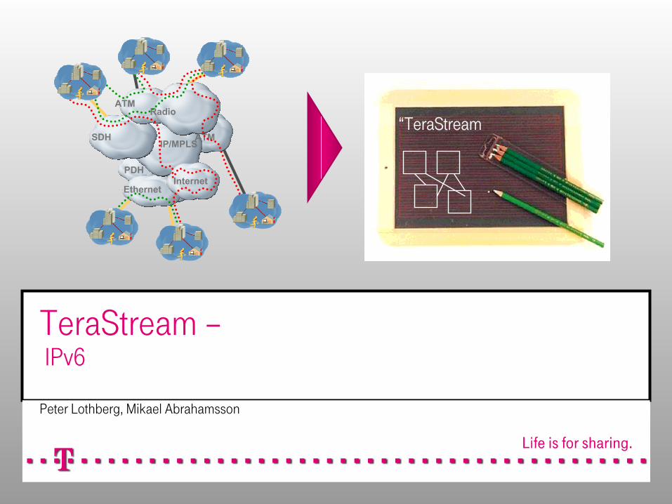
TeraStream –IPv6
Peter Lothberg, Mikael Abrahamsson
PDH
SDH
ATM
Internet
Radio
ATMIP/MPLS
Ethernet
“TeraStream
14-Oct-2013© Deutsche Telekom AG, 2013 212-Sep-2012© Deutsche Telekom AG, 2012 2
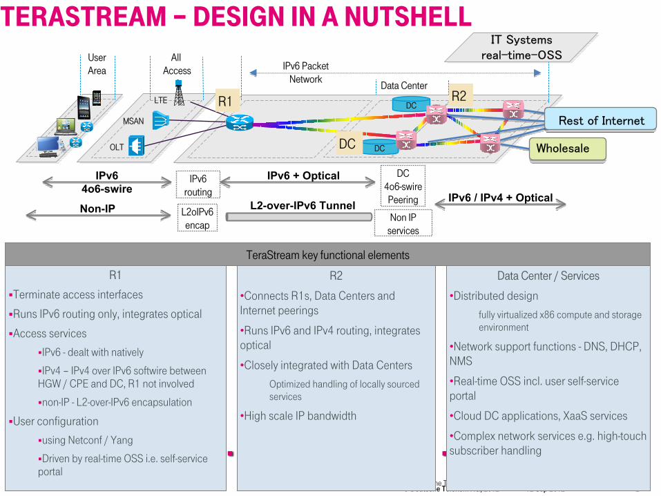
R1
Terminate access interfaces
Runs IPv6 routing only, integrates optical
Access services
IPv6 - dealt with natively
IPv4 – IPv4 over IPv6 softwire between HGW / CPE and DC, R1 not involved
non-IP - L2-over-IPv6 encapsulation
User configuration
using Netconf / Yang
Driven by real-time OSS i.e. self-service portal
All Access
MSAN
OLT
LTE
Data Center
UserArea
DC
DC
IT Systemsreal-time-OSS
R1 R2
IPv6 Packet Network
IPv6 + OpticalIPv6routing
DC4o6-swirePeering
Rest of Internet
Wholesale
IPv6 / IPv4 + OpticalL2-over-IPv6 Tunnel
IPv64o6-swire
Non-IP
DC
L2oIPv6encap
R2
•Connects R1s, Data Centers and Internet peerings
•Runs IPv6 and IPv4 routing, integrates optical
•Closely integrated with Data Centers
Optimized handling of locally sourced services
•High scale IP bandwidth
Data Center / Services
•Distributed design
fully virtualized x86 compute and storage environment
•Network support functions - DNS, DHCP, NMS
•Real-time OSS incl. user self-service portal
•Cloud DC applications, XaaS services
•Complex network services e.g. high-touch subscriber handling
TeraStream key functional elements
Non IPservices
TERASTREAM – DESIGN IN A NUTSHELL

14-Oct-2013© Deutsche Telekom AG, 2013 3
LAYER 1 TOPOLOGY

14-Oct-2013© Deutsche Telekom AG, 2013 4
LAYER 3 TOPOLOGY

14-Oct-2013© Deutsche Telekom AG, 2013 5
0 1 2 3 4 5 60 1 2 3 4 5 6 7!8 9 0 1 2 3 4 5!6 7 8 9 0 1 2 3!4 5 6 7 8 9 0 1!2 3 4 5 6 7 8 9!0 1 2 3 4 5 6 7!8 9 0 1 2 3 4 5!6 7 8 9 0 1 2 3 +-+-+-+-+-+-+-+-+-+-+-+-+-+-+-+-+-+-+-+-+-+-+-+-+-+-+-+-+-+-+-+-+-+-+-+-+-+-+-+-+-+-+-+-+-+-+-+-+-+-+-+-+-+-+-+-+-+-+-+-+-+-+-+-+| REGISTRY/IANA assigned |P|I|E|S S S|R|a a a a a a a a a a a a a a|p p p p p p p p p p p p p|u u u u u u u u|+-+-+-+-+-+-+-+-+-+-+-+-+-+-+-+-+-+-+-+-+-+-+-+-+-+-+-+-+-+-+-+-+-+-+-+-+-+-+-+-+-+-+-+-+-+-+-+-+-+-+-+-+-+-+-+-+-+-+-+-+-+-+-+-+
P Public 0=traffic internal to local SP
I Infrastructure 0=user traffic
E Endpoint/Service 0=network endpoint, 1=service
S Logical Network (Internal ISP#) 0=res, 1=res, 2=internet, 3=res, 4=video, 5=L2 service, 6=voice, 7=management
R Reserved
a R1 Area 14 bit Indicates what R1 that the address is delegated from, max 16,384 R1
p R1 User 13 bit User identifier, max 8192 users
u User subnet Delegated to user
Examples: Source DestinationPIESSS PIESSS
-------------------------------------------------------------------------------User -> Voice 000110 011110Voice -> User 011110 000110User -> User (best effort) X00001 X00001User -> Internet (best effort) 100001 XXXXXXInternet -> User (best effort) XXXXXX 100001Lan-Lan service 010101 010101
2.420111006IPV6 ADDRESSING FORMAT, USERS
14-Oct-2013© Deutsche Telekom AG, 2013 6
10-SEP-2013© Deutsche Telekom AG, 2013 6
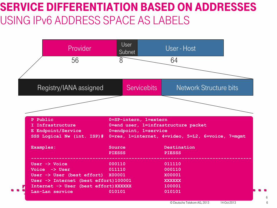
SERVICE DIFFERENTIATION BASED ON ADDRESSESUSING IPv6 ADDRESS SPACE AS LABELS
Provider User - HostUser Subnet
56 8 64
Network Structure bitsServicebitsRegistry/IANA assigned
P Public 0=SP-intern, 1=externI Infrastructure 0=end user, 1=infrastructure packetE Endpoint/Service 0=endpoint, 1=serviceSSS Logical Nw (int. ISP)# 0=res, 1=internet, 4=video, 5=L2, 6=voice, 7=mgmtExamples: Source Destination
PIESSS PIESSS-------------------------------------------------------------------------------User -> Voice 000110 011110Voice -> User 011110 000110User -> User (best effort) X00001 X00001User -> Internet (best effort)100001 XXXXXXInternet -> User (best effort)XXXXXX 100001Lan-Lan service 010101 010101

14-Oct-2013© Deutsche Telekom AG, 2013 7
ROUTINGStatic:
8000 R1's loopbacks (/128 in ISIS)32,000 Internal links (R1-R2 /127 in ISIS)64,000 IBGP routes from R1's (/43 )
3,800,000 IBGP routes that simulates the rest of the Internet
Dynamic:300 IBGP updates from the "outside" per second (/48 prefixes)
emulating flapping (duty cycle 60 on 60 off)64 ISIS updates/second representing random Terastream
internal link failures
ISIS routes for R1’s 8,000Internal links 64,000IPv6 IBGP routes from R1’s 64,000IPv4 routes from external AS to R2 800,000 (not propagated to R1)IPv6 routes received from external AS 3,064,000 (propagated to R1)
14-Oct-2013© Deutsche Telekom AG, 2013 8
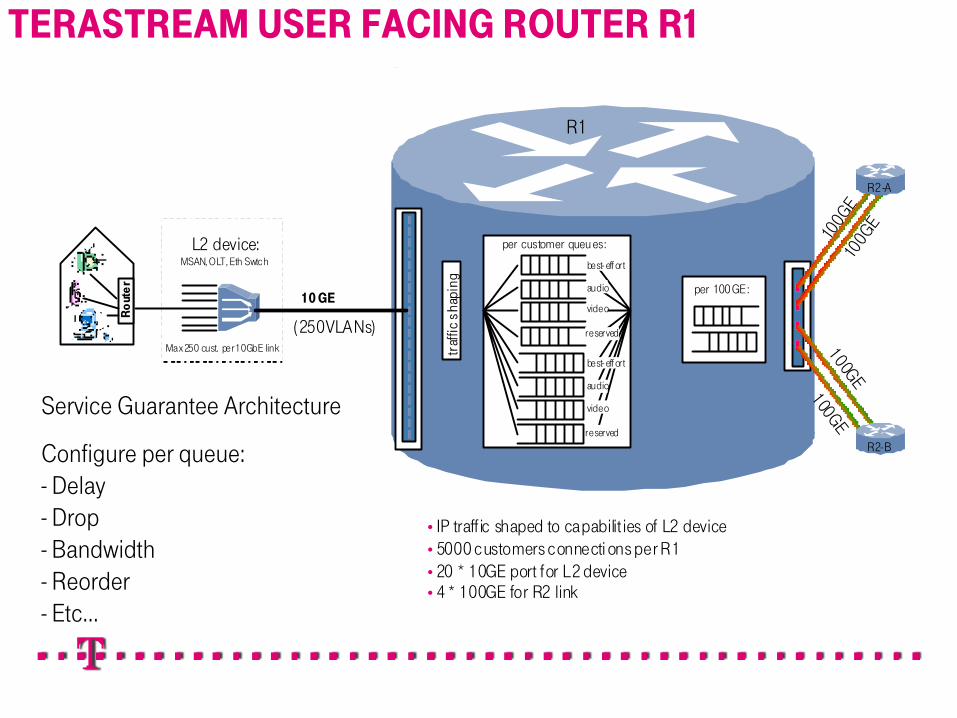
TeraStream user facing router R1
L2 device:MSAN, OLT, Eth Swtch
Ro
ute
r
10 GE
(250VLANs)Max 250 cust. per 10GbE link
•IP traff ic shaped to capabilit ies of L2 device•5000 customers connecti ons per R1•20 * 10GE port for L2 device•4 * 100GE for R2 link
R1
per customer queu es:
100GE
100GE
100GE
100GE
R2-B
R2-A
best- eff ort
audio
video
reserved
best- eff ort
audio
video
reserved
traf
fic s
hapi
ng per 100GE:
TERASTREAM USER FACING ROUTER R1
Service Guarantee Architecture
Configure per queue:- Delay- Drop- Bandwidth- Reorder- Etc...

14-Oct-2013© Deutsche Telekom AG, 2013 9
CARRY POLICY AND BETWEEN ISP AND USER
ISP 1Internet
ISP 2Voice
ISP 3Video
ISP 4For Sale
SGA
TERASTREAM
USER
X
/56/56/56/56
14-Oct-2013© Deutsche Telekom AG, 2013 1010TeraStream Cloud Service Center
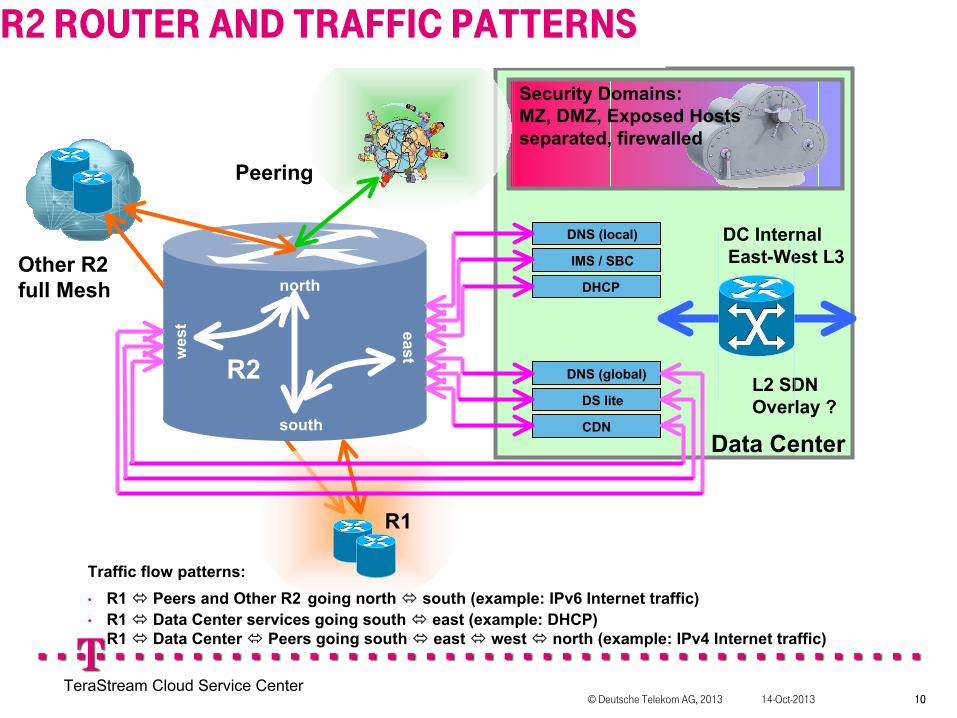
Traffic flow patterns:• R1 Peers and Other R2 going north south (example: IPv6 Internet traffic)• R1 Data Center services going south east (example: DHCP)• R1 Data Center Peers going south east west north (example: IPv4 Internet traffic)
DNS (local)
R2
Data Center
IMS / SBC
DHCP
DS lite
CDN
DNS (global)
Peering
Other R2full Mesh
R1
north
south
wes
t east
DC InternalEast-West L3
L2 SDN Overlay ?
Security Domains:MZ, DMZ, Exposed Hostsseparated, firewalled
R2 ROUTER AND TRAFFIC PATTERNS
14-Oct-2013© Deutsche Telekom AG, 2013 11
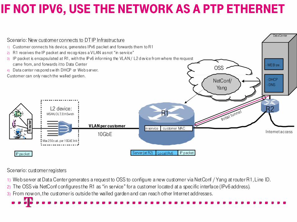
Customer connection usage example
L2 device:MSAN, OLT, Et hSwtch R1
Scenario: New customer connects to DT IP Infrastructure1) Customer connects his device, generates IPv6 packet and forwards them to R12) R1 receives the IP packet and recog nizes a V LAN as not “in serv ice”3) IP packet is encapsulated at R1, wit h the IP v6 infor ming the VLAN / L2 d ev ice fr om where the request
came from, and forwards it to Data Center4) Data center r es pond s w ith DHCP or Web s er ver. Customer can only r each the walled garden.
Rou
ter
R2
V LAN per customer
10GbE
Server (at R2) Lo cal IPv6IP pa cket IP packet
Dat a Center
NetConf/Yang
Max 250 cust . per 10GbE link
in service cu stomer MAC
Scenario: customer registers
1) Web server at Data Center generates a request to OSS to configure a new customer via NetConf / Yang at router R1, Line ID.2) The OSS via NetConf configures the R1 as “in service” for a customer located at a specific interface (IPv6 address).3) From now on, the customer is outside the walled garden and can reach other Internet addresses.
OSS
- DHCP - DNS
Initial tunnel
Internet access
- WEB srv.
IF NOT IPV6, USE THE NETWORK AS A PTP ETHERNET

14-Oct-2013© Deutsche Telekom AG, 2013 12
IPv6
IPv4 decommissioning strategy
The Internal IP network of DT is IPv6. All IPv4 traff ic to and from the customer will be translated to IPv6 at the borders of the network. 2 alternatives are seen as viable:1) Customer IPv4 traffic is encapsulated on IPv6 via DS-lite to a AFTR element located at the Data Center. RFC 6333.
2) Customer IPv4 traffic is translated to IPv6 at the customer’s device (NAT 4to6). (Standard not defined)
In the long term, the expectation is that most customers will beIPv6 capable and that the services will move to IPv6.
In the transition t ime DS lite should provide the mechanism to connect IPv4 devices to other networks.
There is no standard describing NAT 4to6, i.e. translating IPv4 packets to IPv6. This standard remains for further work.
IPv6 IPv4
moves from IPv4 to IPv6
IPv4
AFTR
NAT 4to6*
Data Center
DS lite
* NAT 4to6 – S tandar d not defined
IPV4 DECOMMISSIONING STRATEGY

14-Oct-2013© Deutsche Telekom AG, 2013 13
IPV4 AS A SERVICE – LIGHTWEIGHT 4O6 SOFTWIRES
R1 R2
Home Network
CPEv4 host v4
Internet
v6
Lightweight 4o6 Softwire Tunnel
Concentrator(lwAFTR)
Infrastructure Cloud
v4
IPv4 in IPv6 SoftwireTunnel
IPv4 in IPv6 SoftwireTunnel
14-Oct-2013© Deutsche Telekom AG, 2013 14
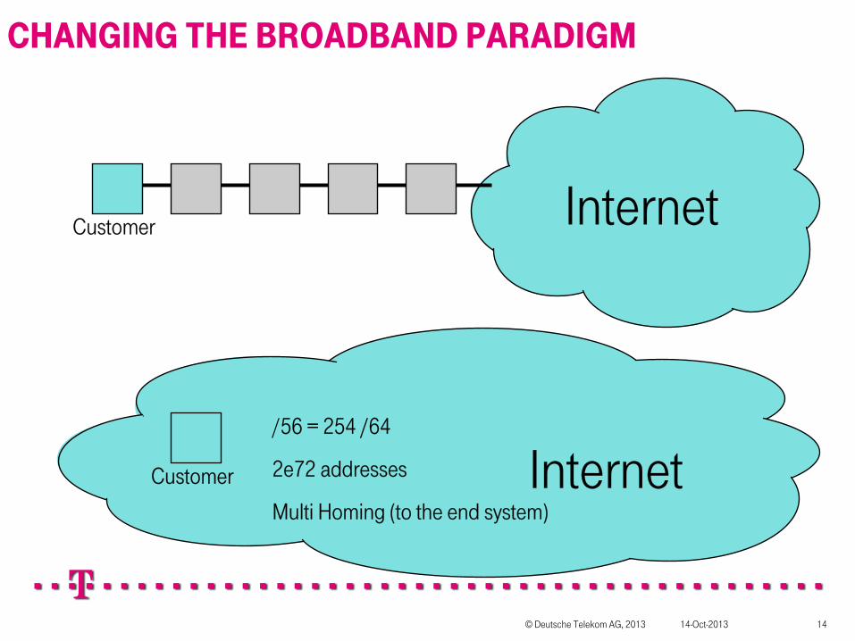
CHANGING THE BROADBAND PARADIGM
Customer Internet
Customer Internet/56 = 254 /64
2e72 addresses
Multi Homing (to the end system)

14-Oct-2013© Deutsche Telekom AG, 2013 15
Home Network
CPEhost
/64 ISP
USUAL HOME NETWORK DRAWINGS

14-Oct-2013© Deutsche Telekom AG, 2013 16
CPE
ISP/64
/64
SOMETIMES LIKE THIS

14-Oct-2013© Deutsche Telekom AG, 2013 17
CPE
ISP/64
/64
PERHAPS EVEN PREFIX DELEGATION!
/64
/64

14-Oct-2013© Deutsche Telekom AG, 2013 18
BG
ISP1/64
/64
WE’RE AIMING TO HANDLE THIS
/64
/64
/64
/64
/64
/64
/64
/64/64
/64
/64
Customer buys these at local electronics store
/64
IG
IG = Interior GatewayBG=Border Gateway
Neighbor/64
ISP2

14-Oct-2013© Deutsche Telekom AG, 2013 19
ISP1/64
/64
... AND THIS
/64
/64
/64
/64
/64
/64
/64 /64
/64
/64
ISP2
ISP3
/64
/64
/64
Multihoming/redundancyArbitrary topologyZero configurationSource based routing
/64
..And there are 239 /64’s left to play with…
BG
BG
BG
IG/BG?

14-Oct-2013© Deutsche Telekom AG, 2013 20
ISP1
3 /64
Multiple prefixes on the same wireEach prefix has meaning = “colour”TV application should use TV prefixPhone application should use phone prefix
Need API for applications to understand thisWork being done in IETF MIF WG
PREFIX COLOURING
14-Oct-2013© Deutsche Telekom AG, 2013 21
ISP1/64
/64
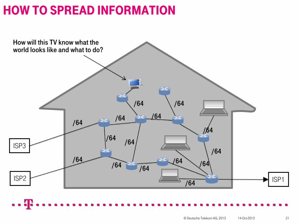
HOW TO SPREAD INFORMATION
/64
/64
/64
/64/64
/64 /64
/64
/64
ISP2
ISP3
/64
/64
How will this TV know what the world looks like and what to do?
/64
/64

14-Oct-2013© Deutsche Telekom AG, 2013 22
BG
ISP1/64
/64
LET’S START FROM THE BEGINNING
/64
/64DHCP
NETCONF
BG starts as host using RA+DHCPFrom DHCP it gets NETCONF server address and cryptographic keysAsks NETCONF server to connect to it (or starts Netconf session on initial TCP session), then tells it capabilities and desired servicesNETCONF server sends service information plus other information to BGNow BG has enough information to become router
IG

14-Oct-2013© Deutsche Telekom AG, 2013 23
BG
ISP1/64
/64
NEXT STEP, SAME THING AGAIN
/64
/64DHCP
NETCONF
IG starts as host using RA+DHCPFrom DHCP it gets NETCONF server address and cryptographic keysNETCONF server sends service information plus other information to BGNow BG has enough information to become router
IG
Things configured include:Prefix and Color informationDNS resolver... etc... Basically anything in DHCP(v6)... And more

14-Oct-2013© Deutsche Telekom AG, 2013 24
BG
ISP1/64
/64
Hosts, same thing again
/64
/64DHCP
NETCON
F
HOST starts as host using RA+DHCPFrom DHCP it gets NETCONF server address and cryptographic keysNETCONF server sends service information plus other information to HOSTNow BG can start using services
IG
14-Oct-2013© Deutsche Telekom AG, 2013 25
ISP1/64
/64
SECURITY
/64
/64
/64
/64
/64
/64
/64 /64
/64
/64
ISP2
ISP3
/64/64
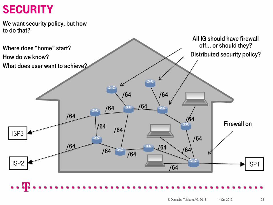
We want security policy, but how to do that?
Where does “home” start?How do we know?What does user want to achieve?
Firewall on
All IG should have firewall off... or should they?
Distributed security policy?
/64
14-Oct-2013© Deutsche Telekom AG, 2013 26
ISP1/64
/64
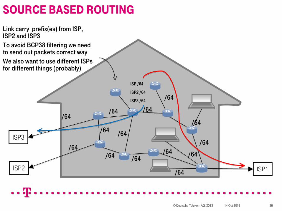
SOURCE BASED ROUTING
/64
/64
/64
/64
ISP /64
ISP2 /64
ISP3 /64
/64
/64 /64
/64
/64
ISP2
ISP3
/64
/64
/64
Link carry prefix(es) from ISP, ISP2 and ISP3To avoid BCP38 filtering we need to send out packets correct wayWe also want to use different ISPs for different things (probably)

14-Oct-2013© Deutsche Telekom AG, 2013 27
ISP1/64
/64
TOPOLOGY DISCOVERY
/64
/64
/64
/64
ISP /64
ISP2 /64
ISP3 /64
/64
/64 /64
/64
/64
ISP2
ISP3
/64
/64
/64
ISIS can make everybody aware of the topology of the network.Work on requirements for ISIS and OSPF is being done in HOMENET.Address family for capabilities and device type?

14-Oct-2013© Deutsche Telekom AG, 2013 28
BR
BOOTSTRAP PROCESS BR
R1 DHCP NETCONF
RA, M=1, A=1
RS
DHCP REQUEST {DNS resolver, netconf, CPE host key}
CPE host key, IPv6 address
Netconf SSH pub key
DHCP ANSWER {DNS resolver, netconf server,Netconf SSH pub key}
Initiate NETCONF session using reverse-SSH with mutual key/cert authentication/verification
Netconf question regarding CPE capabilities (YANG)
Capabilities (YANG)
Provision services available depending on CPE capabilities (YANG)
DHCP REQUEST {DNS resolver, netconf, CPE host key, port info}
DHCP ANSWER {DNS resolver, netconf server,Netconf SSH pub key}

14-Oct-2013© Deutsche Telekom AG, 2013 29
QUESTIONS?
Now you can bring out your tar and feathers and start throwing things at me..
THANKS!