sdh huawei 2500
TRANSCRIPT
OptiX 2500+ Transmission System
OptiX 2500+ Transmission System
SYSTEM OVERVIEW
OptiX 2500+

ContentContent
• Rack and Related Parts
• Sub-rack
• Boards
• Auxiliary Parts
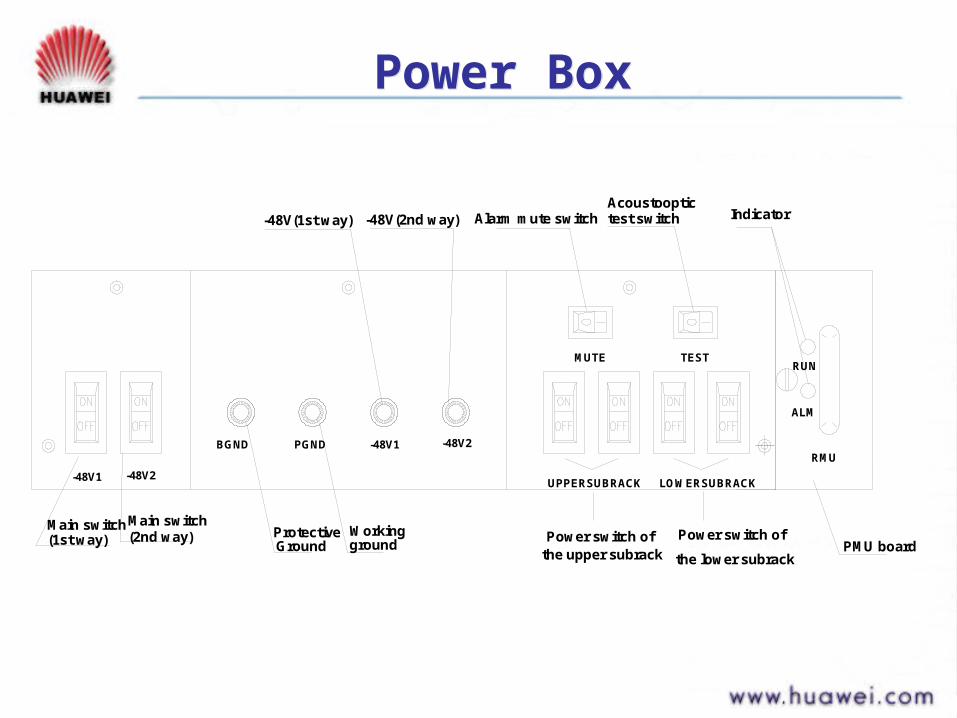
Power BoxPower Box
-48V(1st way) Alarm mute switchAcoustooptic test switch Indicator
Main switch (1st way) Protective
GroundPower switch of
the upper subrack
Working ground
Power switch of
the lower subrackPMU board
Main switch (2nd way)
-48V1 -48V2PGNDBGND
-48V1 -48V2
-48V(2nd way)
UPPERSUBRACK LOWERSUBRACK
RMU
MUTE TEST
ALM
RUN

PMU PMU
1. Generate ringing current 2. Monitor the voltage of the power supply
3. Monitor temperature in the Rack
4. Communicate with the SCC board.
1 2 3 4
Communicate with which sub-rack?
Sub-rackSub-rack
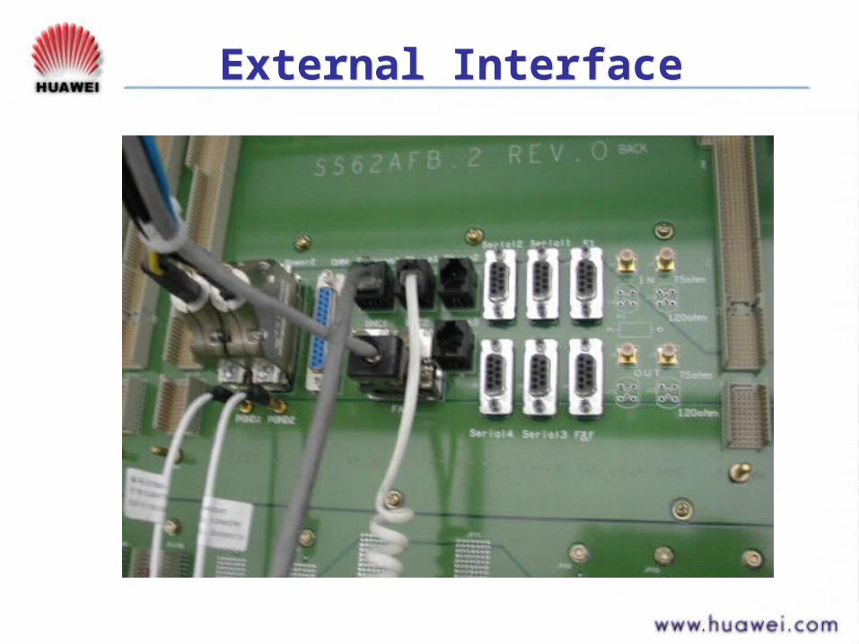
External InterfaceExternal Interface

Board Insertion AreaBoard Insertion Area
Board Insertion Area at the Front Subrack
I II II II II II IX X
U UU UU UU UU UU UC
S
C
C
C
1 72 83 94 105 116 12S S
I
U
P
Optical fiber/electrical cable leading area
FAN
XCS:1+1 protection
SCC:SCC board
IUP:protection slot
IU1~IU4,IU9~IU12:boards need Electrical interface

Access Capacity of IU SlotAccess Capacity of IU Slot
IU slot
1 2 3 4 5 6 7 8 9 10 11 12/P
Capacity 4 4 4 16share
16 16 16 16 16share
4 4 4

System OverviewSystem Overview
Cross-connect Unit
(High-order 96*96 VC-4)
(Low-order 2016*2016 VC-12)
IU
IU
IU
IU
IU
IU
IU
IU
IU
IU
IU
IU
TimingUnit
Axiliaryinterface unit
SCC and OHP unit
Interface Unit Interface Unit
ManagementinterfaceAuxiliary
interfaceExternal sychronization interface

PDH Access UnitPDH Access Unit
What PDH boards do we have in 2500+?
• PD1 : 32×E1• PQ1 : 63×E1• PM1 : 32×E1/T1• PQM : 63×E1/T1• PL3: 3×E3• PD4: 2 X E4

IndicatorIndicator
Green indicator:Operation status indicator
5 times per second : the board is not in working status.
once every other second :the board is in working status.
Twice every other seconds:the communication with the
SCC board is interrupted.

IndicatorIndicator
Red indicator: Alarm Indicator
3 times per second :critical alarm
twice per second:major alarm
once per second :minor alarm
constant on:board failed

SDH Access UnitSDH Access Unit
OptiX 2500+

SDH Access UnitSDH Access Unit
SDH boards in different levels
• S16: 1 x STM16
• SL4: 1 x STM4
• SL1: 1 x STM1
• SD4: 2 x STM4
• SPQ4: 4 x STM-1

SCC BoardSCC Board
OptiX 2500+

SCC BoardSCC Board
PrinciplePrinciple
mailbox
OHP
CPU
DCC
to boards
to boards
NM interface
F& f interface
OAM interfaceAlarm interface
So what can SCC do for us?

SCC BoardSCC Board
ApplicationsApplications
ID--- the only physical identification of NE
ONOFF
D7 D6 D5 D4 D3 D2 D1 D0
ID=9, IP=129.9.0.9
SCC BoardSCC Board
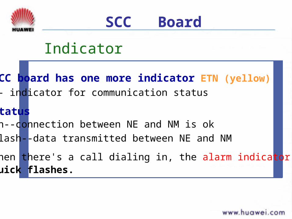
SCC board has one more indicator ETN (yellow)
-- indicator for communication status
statuson--connection between NE and NM is ok
flash--data transmitted between NE and NM
when there's a call dialing in, the alarm indicator willquick flashes.
IndicatorIndicator
SCC BoardSCC Board
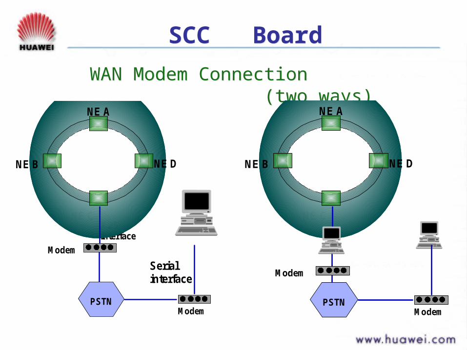
WAN Modem Connection (two ways)WAN Modem Connection (two ways)
X.25 interface
Modem
Modem
Serial interface
NE C
NE B
NE A
NE D
PSTNModem
Modem
NE C
NE B
NE A
NE D
PSTN