sdp143 pilot operated pressure surplussing valve · and safety instructions for pipeline and plant...
TRANSCRIPT

IM-P004-05 CH Issue 5 1
1. Safety information
2. General product information
3. Installation
4. Commissioning
5. Maintenance
6. Spare parts
7. Fault finding
SDP143 Pilot Operated Pressure Surplussing Valve
Installation and Maintenance Instructions
IM-P004-05CH Issue 5
0040226/5
Printed in the UK © Copyright 2007

IM-P004-05 CH Issue 52
1. Safety informationSafe operation of the unit can only be guaranteed if it is properly installed, commissioned, used and maintained by suitably qualified personnel (see Section 1.11) in compliance with the operating instructions. General installation and safety instructions for pipeline and plant construction, as well as the proper use of tools and safety equipment must also be complied with.
1.1 Intended useReferring to the Installation and Maintenance Instructions, name-plate and Technical Information Sheet, check that the product is suitable for the intended use/application. The product listed below complies with the requirements of the European Pressure Equipment Directive 97/23/EC and carries the mark when so required. The product falls within the following Pressure Equipment Directive categories:
Group 2 Product Gases
SDP143 DN15 - DN32 SEP
DN40 - DN80 1
i) The product has been specifically designed for use on steam, air and inert industrial gases which are in Group 2 of the above mentioned Pressure Equipment Directive. The products’ use on other fluids may be possible but, if this is contemplated, Spirax Sarco should be contacted to confirm the suitability
of the product for the application being considered.
ii) Check material suitability, pressure and temperature and their maximum and minimum values. If the maximum operating limits of the product are lower than those of the system in which it is being fitted, or if malfunction of the product could result in a dangerous overpressure or overtemperature occurance, ensure a safety device is included in the system to prevent such over-limit situations.
iii) Determine the correct installation situation and direction of fluid flow.
iv) Spirax Sarco products are not intended to withstand external stresses that may be induced by any system to which they are fitted. It is the responsibility of the installer to consider these stresses and take adequate precautions to minimise them.
v) Remove protection covers from all connections and protective film from all name-plates, where appropriate, before installation on steam or other high temperature applications.
1.2 AccessEnsure safe access and if necessary a safe working platform (suitably guarded) before attempting to work on the product. Arrange suitable lifting gear if required.
1.3 LightingEnsure adequate lighting, particularly where detailed or intricate work is required.
1.4 Hazardous liquids or gases in the pipelineConsider what is in the pipeline or what may have been in the pipeline at some previous time. Consider; flammable materials, substances hazardous to health, extremes of temperature.

IM-P004-05 CH Issue 5 3
1.5 Hazardous environment around the productConsider; explosion risk areas, lack of oxygen (e.g. tanks, pits), dangerous gases, extremes of temperature, hot surfaces, fire hazard (e.g. during welding), excessive noise, moving machinery.
1.6 The systemConsider the effect on the complete system of the work proposed. Will any proposed action (e.g. closing isolation valves, electrical isolation) put any other part of the system or any personnel at risk? Dangers might include isolation of vents or protective devices or the rendering ineffective of controls or alarms. Ensure isolation valves are turned on and off in a gradual way to avoid system shocks.
1.7 Pressure systemsEnsure that any pressure is isolated and safely vented to atmospheric pressure. Consider double isolation (double block and bleed) and the locking or labelling of closed valves. Do not assume that the system has depressurised even when the pressure gauge indicates zero.
1.8 TemperatureAllow time for temperature to normalise after isolation to avoid danger of burns.
1.9 Tools and consumablesBefore starting work ensure that you have suitable tools and/or consumables available. Use only genuine Spirax Sarco replacement parts.
1.10 Protective clothingConsider whether you and/or others in the vicinity require any protective clothing to protect against the hazards of, for example, chemicals, high/low temperature, radiation, noise, falling objects, and dangers to eyes and face.
1.11 Permits to workAll work must be carried out or be supervised by a suitably competent person.Installation and operating personnel should be trained in the correct use of the product according to these instructions.Where a formal 'permit to work' system is in force it must be complied with. Where there is no such system, it is recommended that a responsible person should know what work is going on and, where necessary, arrange to have an assistant whose primary responsibility is safety.Post 'warning notices' if necessary.
1.12 HandlingManual handling of Spirax-Sarco products may present a risk of injury. Lifting, pushing, pulling, carrying or supporting a load by bodily force can cause injury particularly to the back. You are advised to assess the risks taking into account the task, the individual, the load and the working environment and use the appropriate handling method depending on the circumstances of the work being done.

IM-P004-05 CH Issue 54
1.13 Residual hazardsIn normal use the external surface of the product may be very hot. If used at the maximum permitted operating conditions the surface temperature of some products may reach temperatures in excess of 300°C.Many products are not self-draining. Take due care when dismantling or removing the product from an installation (refer to 'Maintenance instructions').
1.14 FreezingProvision must be made to protect products which are not self-draining against frost damage if they are inoperative in environments where they may be exposed to temperatures below freezing point.
1.15 DisposalUnless otherwise stated in the Installation and Maintenance Instructions, this product is recyclable and no ecological hazard is anticipated with its disposal providing due care is taken.
1.16 Returning productsCustomers and stockists are reminded that under UK and EC Health, Safety and Environment Law, when returning products to Spirax Sarco they must provide information on any hazards and the precautions to be taken due to contamination residues or mechanical damage which may present a health, safety or environmental risk. This information must be provided in writing including Health and safety data sheets relating to any substances identified as hazardous.
WarningIf this product is not used in the manner specified by this IMI, then the
protection provided may be impaired.

IM-P004-05 CH Issue 5 5
2. General product information2.1 GeneralThe SDP143 is a cast steel pilot operated pressure surplussing valve suitable for steam, air and industrial gasses (Note: It is not suitable for oxygen service). The SDP143 controls by sensing the upstream pressure through a pressure sensing pipe taken from the pressure pipe union 29 which is clearly identified on Figure 1.
Note: For additional information see the Technical Information sheet TI-P004-01.
2.2 Sizes and pipe connectionsDN15LC - Low Capacity version, DN15, DN20, DN25, DN32, DN40, DN50 and DN80.Flanged to EN 1092 PN40, BS 10 Table 'J', ANSI 300 and ANSI 150.
Fig. 1
Control spring
29 - Connection for upstream pressure control pipe

IM-P004-05 CH Issue 56
2.3 Pressure / temperature limits
The product must not be used in this region.
Due to the material strength of the main diaphragm chamber the product must not be used in this region.
A-D-E Flanged EN 1092 PN40, ANSI 300 and BS 10 Table J.
A-B-C Flanged ANSI 150.
Note: Two colour coded pressure adjustment springs are available for the following downstream pressure ranges: Red 0.2 bar g to 17 bar g Grey 16.0 bar g to 24 bar g
Body design conditions PN40
Maximum design pressure A-B-C 17.2 bar g @ 40°C
A-D-E Limited to 26 bar g
Maximum design temperature 300°C @ 26 bar g
Minimum design temperature 0°C
Maximum upstream pressure for saturated steam service A-D-E 26 bar g
A-B-C 14 bar g
Maximum operating temperature 300°C @ 26 bar g
Minimum operating temperature 0°CNote: For lower operating temperatures consult Spirax Sarco
Maximum differential pressure A-D-E 26 bar
A-B-C 14 bar
Designed for a maximum cold hydraulic test pressure of: 60 bar g
Note: With internals fitted, test pressure must not exceed: 40 bar g
�
���
���
���
� �� �� ��������Pressure bar g
Tem
per
atur
e °C
A B D
C
Steam saturation curve
E

IM-P004-05 CH Issue 5 7
3. Installation
Fig. 2
Control spring
3.1 Supply (Figure 2)The SDP143 surplussing valve is supplied ready for fitting. The control spring used will be the one most suitable for the upstream surplussing pressure quoted on the order but will not be pre-set.
Note: Before actioning any installation observe the 'Safety information' in Section 1.
Connection for upstream pressure control pipe

IM-P004-05 CH Issue 58
3.2 Fitting (Figure 3, opposite)The valve should always be fitted in horizontal pipework with the main diaphragm below the line.
3.3 Pipeline sizingPiping on both sides of the valve must be sized so that the velocities do not exceed 30m/s. This means that a properly sized valve will often be smaller than the connecting pipework.
3.4 Pipeline stressesLine stresses such as could be caused by expansion or inadequate support should not be imposed on the valve body.
3.5 Isolating valvesThese should preferably be of the fullway type.
3.6 Removal of condensateEnsure that the pipework is adequately drained so that the valve is supplied with dry steam. The ideal arrangement is to fit a separator in the steam supply, if the steam is known to be dry then a drain pocket may be adequate.If there is a rise in the downstream pipework from the valve then a drain point should be provided to keep the valve drained after shutdown.
3.7 Preventing dirtThe valve should be protected by a pipeline strainer with 100 mesh screen. The strainer should be fitted on its side to prevent the accumulation of water.
3.8 Upstream pressure control pipeThe upstream pressure control pipe (supplied by others) has to be connected into the upstream pipework. The pilot valve chamber is provided with an 1/8" BSP tapping into which is screwed a steel compression fitting with a stainless steel compression ring. This is suitable for the fitting of 6 mm O/D pipe. If suitable pipe is not available the compression fitting can be removed and " nominal bore steel pipe screwed directly into the pilot valve chamber.The pressure control pipe should be connected into the top of the upstream pipework at a point where in either direction there is a length of straight pipe uninterrupted by fittings for at least 1 m or 15 pipe diameters which ever is the greater.It should be arranged with a positive fall so that any condensate can drain away.Where the size of the main makes it difficult to maintain a fall when entering the top of the main the pressure control pipe may be connected into the side of the main.A stop valve should be fitted for isolating purposes.
3.9 Pressure gaugesIt is useful to fit a pressure gauge just upstream of the valve so that the surplussing pressure can be set accurately.
3.10 BypassIf it is essential to maintain the service supplied by the valve then it may be necessary to install a bypass for use when the surplussing valve is being serviced.The bypass valve will normally be the same size as the surplussing valve. The handwheel should be padlocked to prevent unauthorised use and when in use should be under constant manual supervision.This bypass may be arranged above or to the side of the main assembly but never below it.

IM-P004-05 CH Issue 5 9
Separator
Upstream pressure gauge
Isolating valve
Bypass valve
Isolating valve
Downstream pressure gaugeStrainer
4. Commissioning4.1 Start-up (Setting the valve):- Ensure that all connections are properly made and that all valves are closed.
- Check that the adjustment is turned fully clockwise until the spring is fully compressed.
- Open the small valve in the pressure control line.
- Blow through the approach pipework by removing the cap and screen from the strainer protecting the steam trap draining the upstream pipework. Do not remove the screen from the main line strainer during this operation. Although this should remove most of the dirt which is present it may be necessary to examine and clean the main line strainer at regular intervals.
- Slowly open the upstream isolating valve until it is fully open.
- Slowly open the downstream valve until it is fully open.
- Using a 19 mm A/F spanner slowly turn the screw in an anticlockwise direction until the desired upstream surplussing pressure is obtained.
- Holding the adjustment screw in position with the spanner, tighten down the lock-nut to secure the setting of the adjustment spring, making sure that the 'C' washer stays in position.
Fig. 3
SDP143 surplussing valve
Pressure control
pipe
Steam trap set
1 m or 15 pipe diameters on either side

IM-P004-05 CH Issue 510
5. MaintenanceNote: Before actioning any maintenance programme observe
the 'Safety information' in Section 1.
Safety note:Care should be exercised when handling gaskets since the stainless steel reinforcing strip can easily inflict cuts.
5.1 Routine maintenanceIt is recommended that the valve is dismantled once every 12 to 18 months for a complete overhaul and ideally this should be carried out with the valve removed from the line. The parts that may require replacing or refurbishing are listed below:- Main valve seat (18) and main valve (17).- Pilot valve and seat unit (13).- Internal strainer (14).- Pilot diaphragms (9).- Main diaphragms (24).A detailed procedure for servicing the above items is described in Sections 5.5 to 5.9. In addition to the above items the pushrod (26) liner bush and control orifices (27A and 27B) should if necessary be cleaned of any scale deposits.
5.2 Diaphragms and cleaningIf the valve is dismantled and either the main diaphragms or the pilot diaphragms are not renewed, care must be taken not to turn the diaphragms over - refit them in exactly the same position as when dismantled. The control orifice in the adaptors (27A and 27B) and the interconnecting control pipe assembly (27) as well as the pressure sensing pipework (29A) and pressure pipe union (29) must all be kept clean of dirt.Blow through with compressed air if necessary - do not use a drill on either of the control orifices, one of which contains a split pin, as enlargement of the orifice might upset the operation of the valve.
Main diaphragms used in the SDP143 surplussing valve:
Size of valve Diaphragm diameter
DN15, DN15LC, DN20 125 mm
DN25, DN32 166 mm
DN40, DN50 230 mm
DN80 300 mm
5.3 Control springs and pressure rangesTwo colour coded adjustment springs are available for the following surplussing pressure ranges:
Red 0.2 to 17 bar
Grey 16.0 to 24 bar
IM-P004-05 CH Issue 5 11
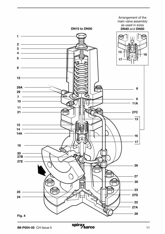
Fig. 4
DN15 to DN50
1
234
5
6
12
7
29
1514
25
24
26
27
30
20
18
22
28
23
8
910
1121
13
17
16
17
1613
Arrangement of the main valve assembly
as used in sizes DN40 and DN50
29A
14A
27B
27A
27D
27C
11A
27E

IM-P004-05 CH Issue 512
5.4 How to renew or change the control springAlthough it is not necessary from a valve safety point of view to isolate the valve in order to change the spring it will probably be necessary from an operational point of view. This is because, with the spring compression load removed, the valve will automatically be in the fully open position.
1. Isolate the surplussing valve and zero the pressure.
2. Release the adjustment lock-nut (2) and turn the adjustment screw (1) anticlockwise until the spring is slack.
3. Slide out the 'C' washer (3) from underneath the lock-nut and remove the spring housing cover (12).
4. Remove the old pressure adjustment spring (6) and replace with a new one remembering to replace the top spring plate (5).
5. Replace the cover and 'C' washer and turn the adjustment screw clockwise until the spring is fully compressed.
6. Bring the valve back into commission by following as many steps as are necessary in Section 4.
5.5 How to renew the pilot valve assembly and bellows seal1. Isolate the surplussing valve and zero the pressure.
2. Release the adjustment lock-nut (2) and turn the adjustment screw (1) anticlockwise until the spring is slack.
3. Slide out the 'C' washer (3) from underneath the lock-nut and remove the spring housing cover (12).
4. Remove the pressure adjustment spring (6) and the top spring plate (5).
5. Undo the 4 x M10 nuts and remove the spring housing (4), bottom spring plate (7) and remove the diaphragms (9) after noting which way they are installed.
6. Undo the union nut (27C) and pressure pipe union (29) and release the 6 mm stainless steel pipework.
7. Undo the 4 nuts (21) and remove the pilot valve housing (10) making sure that the main valve return spring (16) is still positioned correctly on top of the main valve (17).
8. Unscrew the pilot valve and seat unit (13) and the internal strainer screen (14A) by using a 27 mm A/F socket and also remove the plunger (11).
9. Unscrew the bellows seal assembly (11A) using a 24 mm A/F socket. If necessary this bellows assembly can be replaced.
10. With the bellows seal still removed screw in the new pilot valve and seat unit (13) and tighten down to a torque of 115 N m.
11. Insert the pilot valve plunger (11) in from the top and check that there is a gap of 0.7 mm between the top of the plunger and a straight edge placed across the diaphragm location recess (see Figure 5).
Note: Because of production tolerances the plunger is supplied slightly longer than is always required and it will generally be necessary to grind or machine material off the top end to give the correct length. After machining make sure that the sharp edges are removed from the top of the plunger as these could damage the diaphragms. The 0.7 mm gap (see the previous Step 11) ensures that with the bellows seal fitted there is just a slight gap between it and the diaphragm in its neutral position.

IM-P004-05 CH Issue 5 13
12. After locating the bellows seal assembly carefully over the plunger tighten down to a torque of 115 N m.
13. Check with a straight edge again that, with the top of the bellows pressed lightly onto the top of the plunger, there is a slight clearance - a mere line of light, between the straight edge and the top of the bellows (see Figure 5).
14. Before reassembling the valve make sure that the gasket face on both the pilot valve block and the body are clean and that the main valve return spring (16) is positioned correctly on top of the main valve head.
15. Fit the new body gasket (15) and secure the pilot valve block assembly onto the body with the 4 nuts (21) tighten these nuts to the torque shown in Table 1 below.
16. Refit the 6 mm stainless steel pipework and retighten the union nut (27C) and pressure pipe union (29) to ensure a steam tight seal.
17. Refit the two pilot diaphragms (9) making sure that they are fitted the same way round as they were removed and that all contact surfaces are clean. If necessary two new diaphragms can be fitted.
18. Place the bottom spring plate (7) in position and secure the spring housing with the 4 x M10 nuts (8) and tighten to a torque of 50 N m.
19. Replace the pressure adjustment spring (6) and the top spring plate (5) turning the adjustment screw (1) until it just locates on the top spring plate. Replace the spring housing cover (12) and the 'C' washer (3).
20. Bring the valve back into commission by following as many steps as are necessary in Section 4.
Table 1
Recommended tightening torques for pilot valve block securing nuts (item 11)
Size of valve Nut size Tightening torque
DN15, DN20, DN15LC M10 40 N m
DN25 to DN50 M12 60 N m
Note: For DN40 and DN50 valves predating 1996: M16 110 N m
DN80 M12 80 N m
Straight edge
Fig. 5
Straight edge0.7 mm

IM-P004-05 CH Issue 514
5.6 How to clean the pilot valve strainer screen1. Isolate the surplussing valve and zero the pressure.
2. Release the adjustment lock-nut (2) and turn the adjustment screw (1) anticlockwise until the spring is slack.
3. Undo the union nut (27C) and pressure pipe union (29) and release the 6 mm stainless steel pipework.
4. Undo the 4 nuts (21) and remove the pilot valve housing (10) complete with the spring housing assembly, making sure that the main valve return spring (16) is positioned correctly on top of the main valve (17).
5. Holding the pilot valve block upside down, unscrew the strainer retaining nut (14A) using a 27 mm A/F spanner.
6. Remove the internal strainer (14) for cleaning.
7. Refit the screen and strainer retaining nut (14A) tightening it to a torque of 30 N m.
8. Make sure that the gasket faces on both the pilot valve block and body are clean. Make sure that the main valve return spring (16) is positioned correctly on top of the main valve head.
9. Fit the new body gasket (15) and secure the pilot valve block assembly onto the body with the 4 nuts (21). Tighten these nuts to the torque shown in Table 1.
10. Refit the 6 mm stainless steel pipework and retighten the union nut (27C) and the pressure pipe union (29) to ensure a steam tight seal.
11. Bring the valve back into commission by following as many steps as are necessary in Section 4.
5.7 How to renew the pilot valve diaphragms1. Isolate the surplussing valve and zero the pressure.
2. Release the adjustment lock-nut (2) and turn the adjustment screw (1) anticlockwise until the spring is slack.
3. Slide out the 'C' washer (3) from underneath the lock-nut and remove the spring housing cover (12).
4. Remove the pressure adjustment spring (6) and the top spring plate (5).
5. Undo the 4 x M10 nuts (8) and remove the spring housing (4) bottom spring plate (7) and old pilot diaphragms.
6. Refit 2 new pilot diaphragms (9) making sure that all contact faces are clean.
7. Place the bottom spring plate (7) in position and secure the spring housing with the 4 x M10 nuts (8) and tighten to a torque of 50 N m
8. Replace the pressure adjustment spring (6) and the top spring plate (5) turning the adjustment screw (1) until it just locates on the top spring plate. Replace the spring housing cover (12) and the 'C' washer (3).
9. Bring the valve back into commission by following as many steps as are necessary in Section 4.

IM-P004-05 CH Issue 5 15
Fig. 6
5.8 How to renew the main diaphragms1. Isolate the surplussing valve and zero the pressure.
2. Undo the long union nut (27D) and pull it away.
3. Undo the M12 nuts and bolts (23) and drop away from the main diaphragm chamber (22) and the main diaphragm plate and pushrod assembly (25 and 26).
4. Thoroughly clean the lower diaphragm chamber and make sure that the contact surfaces are clean.
5. Replace main diaphragm plate and pushrod assembly (25 and 26) and loosely refit the lower diaphragm chamber (22) on the two bolts either side of the union connection, see Figure 6, so that the spigot is located into the recess. Also ensure that the connecting stainless steel pipework is located into its fitting.
6. Bring the two main diaphragms together and slide into position, first easing the diaphragm plate upwards to clear, see Figure 5.
7. With the main diaphragms in position, push the lower chamber home to locate the recess and refit the M12 nuts and bolts (23) tighten to a torque of 75 N m.
8. Retighten the long union nut (27D) to ensure a steam tight seal on the stainless steel pipework.
9. Bring the valve back into commission by following as many steps as are necessary in Section 4.

IM-P004-05 CH Issue 516
5.9 How to service or renew the main valve and seat1. Isolate the surplussing valve and zero the pressure.
2. Undo the union nut (27C) and the pressure pipe union nut (29) and release the 6 mm stainless steel pipework.
3. Undo the 4 nuts (21) and remove the pilot valve housing (10) complete with the spring housing assembly.
4. Remove the main valve return spring (16) and the main valve (17).
5. Using a socket (see Table 2) remove the main valve seat (18).
6. The seating faces of the main valve head and main valve seat may now be examined. If they are only slightly worn both the main valve head and main valve seat may be lapped on a flat plate using a fine grinding paste.
7. If either is badly worn or unfit for further use they will need to be replaced. However as the seats and valve heads are not supplied as matched pairs it is not particularly necessary to replace both items.
8. Making sure that the threads and seating surface in the body are clean, refit the seat and tighten to the torque shown in Table 2.
9. Where a part had been fitted or where extensive lapping has taken place, it will be necessary to reset the main valve pushrod (26 ) to give the correct valve lift.
10. To do this it is necessary to expose the main diaphragm plate and pushrod assembly by following Steps 2 and 3 in Section 5.8.
11. Refit the pushrod (26) and replace the main valve (17) making sure it is located onto the main seat.
12. The main valve can now be opened by pushing on the main diaphragm plate (25) until it comes up against the stop on the body, see Figure 7. Check the valve lift by using a depth gauge as shown.
13. If the lift is different from that shown in the Table 3, slacken the lock-nut (30) and adjust the lift by screwing the pushrod (26) in or out of the main diaphragm plate (25). When the lift is correct, retighten the lock-nut (30).
Table 2 Recommended tightening torques for main valve seat (item 22)
Size of valve Size of socket across flats Tightening torque
DN15, DN15LC 30 mm 110 - 120 N m
DN20 36 mm 140 - 150 N m
DN25 41 mm 170 - 180 N m
DN32 46 mm 200 - 210 N m
DN40 60 mm 300 - 310 N m
DN50 65 mm 400 - 410 N m
DN80 - 600 - 700 N m

IM-P004-05 CH Issue 5 17
Fig. 7
Table 3Size of valve Lift
DN15, DN15LC 2.0 mm
DN20 2.5 mm
DN25 3.0 mm
DN32 3.5 mm
DN40 4.5 mm
DN50 5.0 mm
DN80 8.0 mm
14. Replace lower end of valve by following Steps 4 to 8 in Section 5.8.
15. Make sure that the gasket faces on both the pilot valve block and body are clean. Refit the main valve (17) and replace the main valve return spring (16) correctly on top of the main valve head.
16. Fit the new body gasket (15) and secure the pilot valve housing (10) onto the body with the 4 nuts (21). Tighten these to the torque shown in Table 1.
17. Refit the 6 mm stainless steel pipework and retighten the union nut (27C) and the pressure pipe union (29) to ensure a steam tight seal.
18. Bring the valve back into commission by following as many steps as are necessary in Section 4.

IM-P004-05 CH Issue 518
6. Spare partsAvailable sparesMaintenance kit A stand-by set of spares for general maintenance purposes and covers all spares marked*Main diaphragm (2 off) A
Pilot diaphragm (2 off) B
Pilot valve seal assembly C
Pilot valve and plunger assembly D, E
Main valve assembly F, H
Main valve return spring G
Red 0.2 to 17 barPressure adjustment spring
Grey 16 to 24 bar J
Control pipe assembly KBody gasket (packet of 3) O
Set of spring housing securing studs and nuts (set of 4) P
Set of pilot valve housing securing studs and nuts (set of 4) Q
(set of 10) DN15 and DN20
Set of diaphragm chamber securing bolts and nuts (set of 12) DN25 and DN32
R (set of 16) DN40 and DN50
(set of 20) DN80
Set of main body studs and nuts (DN80) (set of 6) TPushrod, lock-nut and main diaphragm plate assembly V, W, X
How to order sparesAlways order spares by using the description given in the column headed 'Available spares' and state the size and type of pressure reducing valve. Example: 1 - Main valve assemblyfor a Spirax Sarco DN15 SDP143 pilot operated pressure surplussing valve.
Interchangeability of sparesThe following Table shows how some parts are interchangeable. For example the line headed 'Main diaphragm' indicates that the diaphragm used in sizes DN15LC, DN15 and DN20 is common to those sizes by the letter 'a'. The letter 'b' indicates that sizes DN25 and DN32 use one common diaphragm.
Spare parts DN15LC DN15 DN20 DN25 DN32 DN40 DN50 DN80Main diaphragm a a a b b c c d
Pilot diaphragm a a a a a a a a
Pilot valve seal assembly a a a a a a a a
Pilot valve and plunger assembly a a a a a a a a
Main valve assembly a b c d e f g h
Main valve return spring a a a b b c c d
Pressure adjustment spring a a a a a a a a
Control pipe assembly a a b c d e f g
Body gasket a a a b b c c d
Set of spring housing securing studs and nuts a a a a a a a a
Set of pilot valve housing securing studs and nuts a a a b b c c d
Set of diaphragm chamber securing bolts and nuts a a a b b c c d
Set of main body studs and nuts − − − − − − − a
*
*
*
*
*
*

IM-P004-05 CH Issue 5 19
Fig. 8
B
C
Q
P
K
A
R
R
J
Q
H
F
O
D
E
PG
TArrangement of main diaphragm chamber DN80 size only.
V
W
X

IM-P004-05 CH Issue 520
7. Fault finding7.1 Preliminary check1. Isolate the surplussing valve and zero the pressure.2. Release the lock-nut (2) and turn the adjustment screw clockwise until the spring is fully compressed.3. Undo the union nut (27C) and release the pipework.4. Turn on the steam slowly. If steam is discharging from the coupling in the pilot valve block, it indicates that the pilot valve is failing to seat.5. If steam is discharging from the stainless steel pipework it indicates that the main valve is failing to seat.
7.2 Valve fails to open at required pressureIf the valve does not open when the upstream pressure reaches the pressure to which it has been set then it could be caused by one of the following:1. No upstream pressure steam reaching the valve. Check that the isolating valves are open and the strainer is clear. (A pressure gauge permanently fitted on the upstream side is most useful).2. Control spring set too high.3. Upstream pressure control pipe blocked. Dismantle and blow through to clear obstruction.4. Pipe assembly (27) blocked. Remove by uncoupling the union nuts (27, 27C and 27D), blow through to clear obstruction.5. Pilot valve diaphragms fractured. Check and replace as Section 5.7.6. Main diaphragms fractured. Check and replace as Section 5.8.
7.3 Valve fails to closeIf the valve fails to close when the upstream pressure drops below the pressure to which it has been set then it could be caused by one of the following:1. Main valve (17) not seating. Check as Section 5.92. Pilot valve (14) or pilot valve plunger (11) is sticking. For access see Section 5.53. Main valve pushrod (26) sticking. Check and remove as Section 5.8.4. Control orifice (27A) blocked. Unscrew the union (27E) and the fitting (27B) from the side of the body and clean out, making sure to replace the split pin.5. Pilot valve plunger is too short. Check as Section 5.5 and replace if necessary.6. Pressure adjustment spring is broken.
7.4 Valve opens at set pressure but upstream pressure still risesIf the valve opens at the required set pressure but the upstream pressure continues to rise then it could be caused by one of the following:1. The valve is undersized for the surplussing capacity required.2. The lift on the main valve (17) is not set correctly. Check as Section 5.9 and reset the lift if necessary.3. Pilot valve plunger is too long. Check as Section 5.5 and shorten if necessary.