sdw-550 - westermo industrial data communications ... · pdf file6644-2230 3 1. description...
TRANSCRIPT
Industrial Ethernet5-port Switch
www.westermo.com
©W
este
rmo
Tele
indu
stri
AB
• 20
05User Guide
6644-2230
SDW-550
2 6644-2230
Contents
1. Description .................................................................................................................................................................................................... 3
2. Safety ................................................................................................................................................................................................................. 4–5
3. Approvals .......................................................................................................................................................................................................... 53.1 Declaration of Conformity ................................................................................................................................................... 6
4. Specification ................................................................................................................................................................................................ 7
5. Maintenance ................................................................................................................................................................................................ 8
6. Installation ...................................................................................................................................................................................................... 8
6.1 Mounting / Removal ....................................................................................................................................................................... 86.2 Connections ............................................................................................................................................................................................. 9
6.2.1 Power .............................................................................................................................................................................................. 106.2.2 TX ....................................................................................................................................................................................................... 10
6.3 DIP switch settings SDW-550 ........................................................................................................................... 11–136.5 LED indicators .................................................................................................................................................................................. 14
36644-2230
1. DescriptionThe SDW-550 is an Industrial Ethernet 5-port switch.
All ports support auto-negotiation, but DIP-switches also allow speed and duplex configuration of any individual TX port. It is also possible to set up one port to monitor traffic to/from the switch.
The SDW-550 has been designed to meet high industrial specifications, providing very high dependability in harsh environmental conditions.
Features:… TX shields individually isolated
… Wide DC power range 12-48 VDC
… Wide temperature range
… Automatic MDI/MDI-X crossover
… LED indicators for Power, Speed, Duplex, Link and Traffic
… Port monitoring
… 35 mm DIN rail mounting
… Enable or disable of flow control
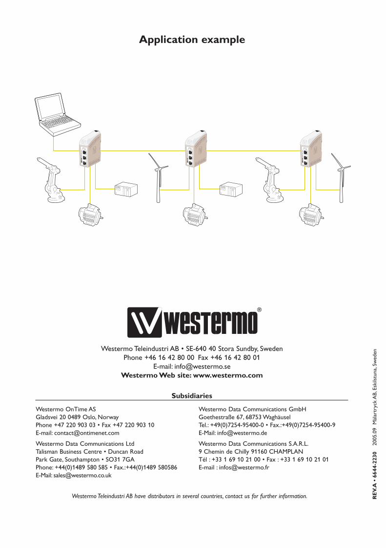
Example of applications are:… 5-port switch
… Ethernet isolator, for STP networks
4 6644-2230
2. SafetyGeneral:
Before using this unit, read this manual completely and gather all information onthe unit. Make sure that you understand it fully. Check that your application doesnot exceed the safe operating specifications for this unit.
Before installation, maintenance or modification work:
Prevent damage to internal electronics from electrostatic discharges (ESD) by discharging your body to a grounding point (e.g. use of wrist strap).
Prevent access to hazardous voltages by disconnecting the unit from DC mainssupply and all other electrical connections.
When installed, should the unit and it's wiring be separated from hazardous voltage by double or reinforced insulation.
Installation:
This unit should only be installed by qualified personnel.
This unit should only be installed in a "restricted access area", for example a lock-able cabinet where access is restricted to service personnel only.
This unit is intended for permanent connection to the DC mains supply.
The power supply wiring must be sufficiently fused, and if necessary must be pos-sible to disconnect manually from the DC mains supply. Ensure compliance tonational installation regulations.
Prevent access to hazardous voltage by disconnecting the unit from power supply.
Warning! Do not open connected unit. Hazardous voltage may occur within thisunit when connected to power supply.
This unit uses convection cooling.To avoid obstructing the air flow around theunit, follow the spacing recommendations (see Installation section).
!
!
!
56644-2230
3. ApprovalsConformity with the Directive 73/23/EEC Low Voltage Directive – LVD has beenassessed by application of the standard EN 60 950.
Conformity with the Directive 89/336/EEC Electromagnetic Compatibility (EMC)has been assessed by application of standards EN 61000-6-2 (industrial immunity)and EN 61000-6-3 (residential emission).
Care recommendationsFollow the care recommendations below to maintain full operation of unit and to fulfilthe warranty obligations.This unit must not be operating with removed covers or lids.Do not attempt to disassemble the unit.There are no user serviceable parts inside.Do not drop, knock or shake the unit, rough handling above the specification may causedamage to internal circuit boards.Do not use harsh chemicals, cleaning solvents or strong detergents to clean the unit.Do not paint the unit. Paint can clog the unit and prevent proper operation.Do not expose the unit to any kind of liquids (rain, beverages, etc).The unit is not water-proof. Keep the unit within the specified humidity levels.Do not use or store the unit in dusty, dirty areas, connectors as well as other mechanicalpart may be damaged.If the unit is not working properly, contact the place of purchase, nearest Westermo dis-tributor office or Westermo Tech support.

6 6644-2230
3.1 Declaration of Conformity
Westermo Teleindustri AB
Declaration of conformity
Org.nr/Postadress/Postal address Tel. Telefax Postgiro Bankgiro Corp. identity number Registered office
S-640 40 Stora Sundby 016-428000 016-428001 52 72 79-4 5671-5550 556361-2604 Eskilstuna
Sweden Int+46 16428000 Int+46 16428001
The manufacturer Westermo Teleindustri AB
SE-640 40 Stora Sundby, Sweden
Herewith declares that the product(s)
Type of product Model Art no Installation manual
DIN-rail SDW-550 3644-0001 6644-2230
is in conformity with the following EC directive(s).
No Short name
89/336/EEG Electromagnetic Compatibility (EMC)
References of standards applied for this EC declaration of conformity.
No Title Issue
EN 61000-6-2 Immunity for industrial environments 2 (2001)
EN 61000-6-3 Emission standard for residential, commercial and
light-industrial environments
1 (2001)
The last two digits of the year in which the CE marking was affixed: 05
Hans Levin
Technical Manager
15th December2004
76644-2230
4. Specification
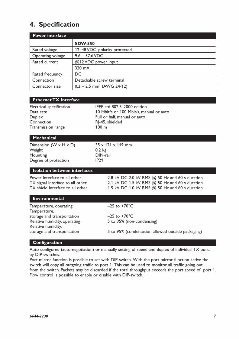
SDW-550Rated voltage 12–48 VDC, polarity protectedOperating voltage 9.6 – 57.6 VDCRated current @12 VDC power input
320 mA Rated frequency DCConnection Detachable screw terminalConnector size 0.2 – 2.5 mm2 (AWG 24-12)
Power interface
Ethernet TX Interface
Electrical specification IEEE std 802.3. 2000 editionData rate 10 Mbit/s or 100 Mbit/s, manual or autoDuplex Full or half, manual or autoConnection RJ-45, shieldedTransmission range 100 m
Mechanical
Dimension (W x H x D) 35 x 121 x 119 mmWeight 0.2 kgMounting DIN-railDegree of protection IP21
Isolation between interfaces
Power Interface to all other 2.8 kV DC 2.0 kV RMS @ 50 Hz and 60 s durationTX signal Interface to all other 2.1 kV DC 1.5 kV RMS @ 50 Hz and 60 s durationTX shield Interface to all other 1.5 kV DC 1.0 kV RMS @ 50 Hz and 60 s duration
Environmental
Temperature, operating –25 to +70°C Temperature,storage and transportation –25 to +70°CRelative humidity, operating 5 to 95% (non-condensing)Relative humidity,storage and transportation 5 to 95% (condensation allowed outside packaging)
Configuration
Auto configured (auto-negotiation) or manually setting of speed and duplex of individual TX port,by DIP-switches.Port mirror function is possible to set with DIP-switch. With the port mirror function active theswitch will copy all outgoing traffic to port 1. This can be used to monitor all traffic going out from the switch. Packets may be discarded if the total throughput exceeds the port speed of port 1.Flow control is possible to enable or disable with DIP-switch.
8 6644-2230
5. MaintenanceNo maintenance is required, as long as the unit is used as intended within the specifiedconditions.
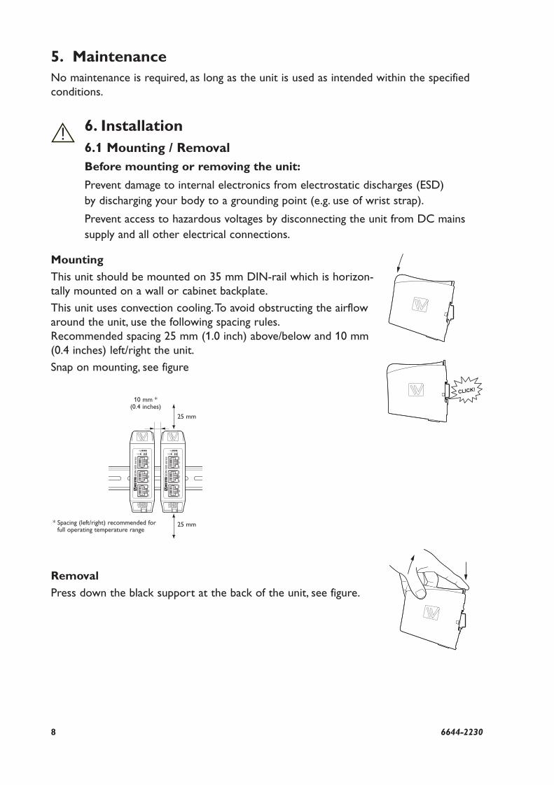
6. Installation6.1 Mounting / RemovalBefore mounting or removing the unit:
Prevent damage to internal electronics from electrostatic discharges (ESD) by discharging your body to a grounding point (e.g. use of wrist strap).
Prevent access to hazardous voltages by disconnecting the unit from DC mainssupply and all other electrical connections.
Mounting
This unit should be mounted on 35 mm DIN-rail which is horizon-tally mounted on a wall or cabinet backplate.
This unit uses convection cooling.To avoid obstructing the airflowaround the unit, use the following spacing rules.Recommended spacing 25 mm (1.0 inch) above/below and 10 mm(0.4 inches) left/right the unit.
Snap on mounting, see figure
Removal
Press down the black support at the back of the unit, see figure.
10 mm *(0.4 inches)
!
25 mm
25 mm* Spacing (left/right) recommended forfull operating temperature range
CLICK!

96644-2230
6.2 Connections
Power connection
NetworkRJ-45 connection
NetworkRJ-45 connection
LED indicators
Available models:
… SDW-550 10/100Base-T/TX: 5 ports

10 6644-2230
6.2.1 PowerThe SDW-550 supports redundant power connection.The positive input are +VA and +VB, the negative input for both supplies are COM.The power is drawn from the input with the highest voltage.
6.2.2 TXEthernet TX connection (RJ-45 connector), automatic MDI/MDI-X crossover.
Contact Signal Name Direction Description/Remark
1 TD+ In/Out Transmitted/Received data
2 TD– In/Out Transmitted/Received data
3 RD+ In/Out Transmitted/Received data
4
5
6 RD– In/Out Transmitted/Received data
7
8
Shield HF-connected
CAT 5 cable is recommended.Unshielded (UTP) or shielded (STP) connector might be used.
87654321
3-pos screw terminal Description
1 COM
2 +VA
3 +VB
12
3
116644-2230
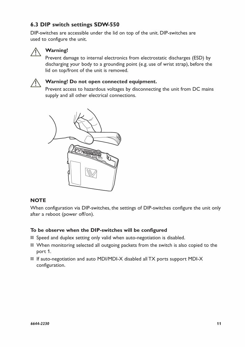
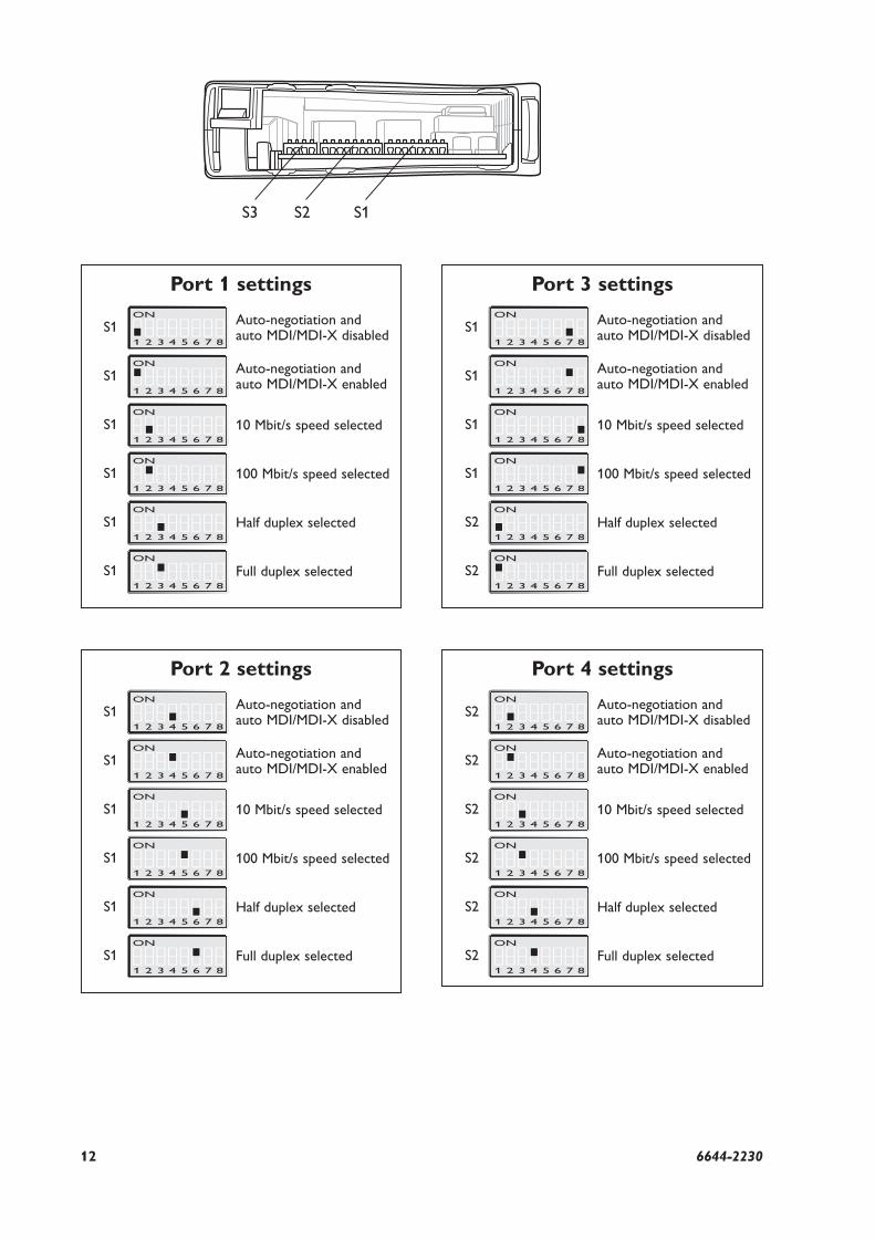
6.3 DIP switch settings SDW-550DIP-switches are accessible under the lid on top of the unit. DIP-switches are used to configure the unit.
Warning!
Prevent damage to internal electronics from electrostatic discharges (ESD) by discharging your body to a grounding point (e.g. use of wrist strap), before the lid on top/front of the unit is removed.
Warning! Do not open connected equipment.
Prevent access to hazardous voltages by disconnecting the unit from DC mainssupply and all other electrical connections.
!
!
NOTE
When configuration via DIP-switches, the settings of DIP-switches configure the unit onlyafter a reboot (power off/on).
To be observe when the DIP-switches will be configured
… Speed and duplex setting only valid when auto-negotiation is disabled.
… When monitoring selected all outgoing packets from the switch is also copied to theport 1.
… If auto-negotiation and auto MDI/MDI-X disabled all TX ports support MDI-X configuration.
12 6644-2230
S3 S2
Port 3 settingsON
1 2 3 4 5 6 7 8
S1 Auto-negotiation and auto MDI/MDI-X disabled
ON
1 2 3 4 5 6 7 8
S1 Auto-negotiation and auto MDI/MDI-X enabled
ON
1 2 3 4 5 6 7 8
S1 10 Mbit/s speed selected
ON
1 2 3 4 5 6 7 8
S1 100 Mbit/s speed selected
ON
1 2 3 4 5 6 7 8
S2 Half duplex selected
ON
1 2 3 4 5 6 7 8
S2 Full duplex selected
Port 1 settingsON
1 2 3 4 5 6 7 8
S1 Auto-negotiation and auto MDI/MDI-X disabled
ON
1 2 3 4 5 6 7 8
S1 Auto-negotiation and auto MDI/MDI-X enabled
ON
1 2 3 4 5 6 7 8
S1 10 Mbit/s speed selected
ON
1 2 3 4 5 6 7 8
S1 100 Mbit/s speed selected
ON
1 2 3 4 5 6 7 8
S1 Half duplex selected
ON
1 2 3 4 5 6 7 8
S1 Full duplex selected
Port 2 settingsON
1 2 3 4 5 6 7 8
S1 Auto-negotiation and auto MDI/MDI-X disabled
ON
1 2 3 4 5 6 7 8
S1 Auto-negotiation and auto MDI/MDI-X enabled
ON
1 2 3 4 5 6 7 8
S1 10 Mbit/s speed selected
ON
1 2 3 4 5 6 7 8
S1 100 Mbit/s speed selected
ON
1 2 3 4 5 6 7 8
S1 Half duplex selected
ON
1 2 3 4 5 6 7 8
S1 Full duplex selected
Port 4 settingsON
1 2 3 4 5 6 7 8
S2 Auto-negotiation and auto MDI/MDI-X disabled
ON
1 2 3 4 5 6 7 8
S2 Auto-negotiation and auto MDI/MDI-X enabled
ON
1 2 3 4 5 6 7 8
S2 10 Mbit/s speed selected
ON
1 2 3 4 5 6 7 8
S2 100 Mbit/s speed selected
ON
1 2 3 4 5 6 7 8
S2 Half duplex selected
ON
1 2 3 4 5 6 7 8
S2 Full duplex selected
S1
136644-2230
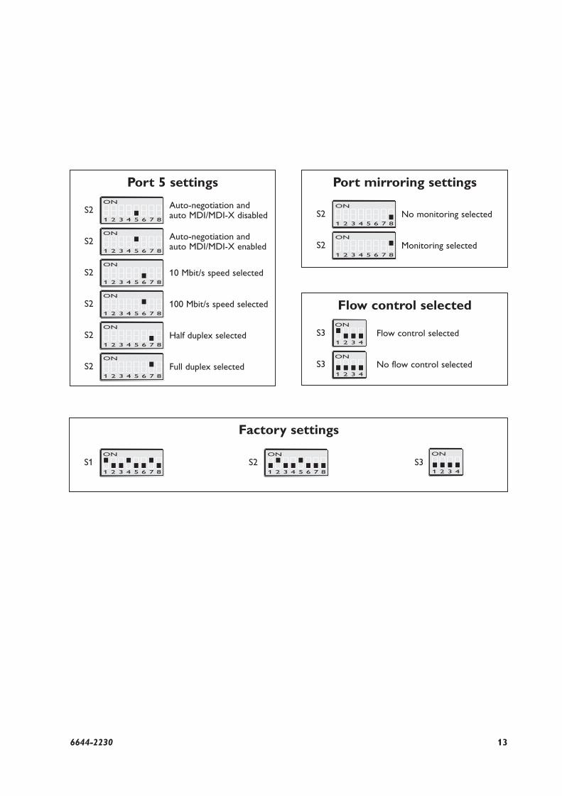
Port 5 settingsON
1 2 3 4 5 6 7 8
S2 Auto-negotiation and auto MDI/MDI-X disabled
ON
1 2 3 4 5 6 7 8
S2 Auto-negotiation and auto MDI/MDI-X enabled
ON
1 2 3 4 5 6 7 8
S2 10 Mbit/s speed selected
ON
1 2 3 4 5 6 7 8
S2 100 Mbit/s speed selected
ON
1 2 3 4 5 6 7 8
S2 Half duplex selected
ON
1 2 3 4 5 6 7 8
S2 Full duplex selected
Port mirroring settings
ON
1 2 3 4 5 6 7 8
S2 No monitoring selected
ON
1 2 3 4 5 6 7 8
S2 Monitoring selected
Flow control selected
S3 Flow control selected
S3 No flow control selected
Factory settings
ON
1 2 3 4 5 6 7 8
S1ON
1 2 3 4 5 6 7 8
S2 S3ON
1 2 3 4
ON
1 2 3 4
ON
1 2 3 4

14 6644-2230
6.5 LED indicatorsAt power on the PWR flashes during initialising.
Indicators (LED) Power (PWR)Link (LINK) of every portSpeed (SPD) and duplex (DPX) of TX ports
LED Status Indication of
PWR ON Internal power, initialising OK
Slow flash Initialisation progressing
Fast flash Initialisation error
LINK OFF No Ethernet link
ON Good Ethernet link
Flash Ethernet data is transmitted or received, traffic indication
SPD OFF 10 Mbit/s
(TX only) ON 100 Mbit/s
DPX OFF Half duplex
(TX only) ON Full duplex

RE
V.A
• 6
644-
2230
2005
.09
Mäl
artr
yck
AB
,Esk
ilstu
na,S
wed
en
Application example
Westermo Teleindustri AB • SE-640 40 Stora Sundby, SwedenPhone +46 16 42 80 00 Fax +46 16 42 80 01
E-mail: [email protected] Web site: www.westermo.com
Westermo Teleindustri AB have distributors in several countries, contact us for further information.
Westermo OnTime ASGladsvei 20 0489 Oslo, NorwayPhone +47 220 903 03 • Fax +47 220 903 10E-mail: [email protected]
Westermo Data Communications LtdTalisman Business Centre • Duncan RoadPark Gate, Southampton • SO31 7GAPhone: +44(0)1489 580 585 • Fax.:+44(0)1489 580586E-Mail: [email protected]
Westermo Data Communications GmbHGoethestraße 67, 68753 WaghäuselTel.: +49(0)7254-95400-0 • Fax.:+49(0)7254-95400-9E-Mail: [email protected]
Westermo Data Communications S.A.R.L.9 Chemin de Chilly 91160 CHAMPLANTél : +33 1 69 10 21 00 • Fax : +33 1 69 10 21 01E-mail : [email protected]
Subsidiaries