seals flow code development - nasa conference publication 10070 seals flow code development...
TRANSCRIPT

NASA Conference Publication 10070
Seals Flow CodeDevelopment
(NASA-CP-10070) SEALS FLOd GOOF DtVELOPMFNT N92-15GR2(NASA) 172 p CSCL 11A —TH
N92-1Un
G3/16 0053
Proceedings of a workshop held atNASA Lewis Research Center
Cleveland, OhioMarch 26, 1991
NASA
https://ntrs.nasa.gov/search.jsp?R=19920005864 2018-05-31T00:43:39+00:00Z

NASA Conference Publication 10070
Seals Flow CodeDevelopment
Proceedings of a workshop held atNASA Lewis Research Center
Cleveland, Ohio
March 26, 1991
NASANational Aeronautics and
Space Administration
Office of Management
Scientific and TechnicalInformation Program
1991

CONTENTS
Page
Summary 1
MORNING SESSION
Presentation of NASA Contract NASA-25644"Numerical/Analytical/Experimental Study of
Fluid Dynamic Forces in Seals"
Introduction 7
Industrial Code Development 15
Development of a CFD Code for Analysis of Fluid Dynamic Forces in Seals . . 27
KBS Development 41
KBS Demonstration 47
AFTERNOON SESSIONPresentations by Participants
Seals Related Research at Lewis Research Center 53
MSFC Hydrostatic Bearing Activities 67
Army Research Concerns in Engine Sealing 75
Seals Research at Texas A&M University 83
Seals Research at the University of Akron 101
Programs at Wright Patterson Air Force Base 103
Seal Development Activities at Allison Turbine Division 107
Areas of Seal R&D at GE 109
Seal Related Development Activities at EG&G 113
The Application of Differential Roughness to MitigateFriction and Wear (Mechanical Seal Technology) 125
Seal Technology at Rocketdyne 127
CFD Activities at Aerojet Related to Seals and Fluid Film Bearing .... 133
Pratt and Whitney Activities 139
CFD Applications in Propulsion 145
... PRECEDING PAGE BLANK NOT FILMED

Status Update on the Seal/Bearing Rotordynamics Test Facility atCase Western Reserve University 155
Seal Test Program at MIT 163
National Aerospace Plane Engine Seals 165
Volume Visualization and Knowledge Integration 171
Fluid Seals Technology at BHR Group Ltd 173
Appendix A - Workshop Agenda 175
Appendix B - Workshop Attendance List 177
SUMMARY
In recognition of a deficiency in the current modeling capability for seals, aseven-year effort was established in 1990 by NASA's Office of Aeronautics,Exploration, and Technology under the Earth-to-Orbit Propulsion program of theCivilian Space Technology Initiative to develop verified computational-fluid-dynamic (CFD) concepts, codes, and analyses for seals.
The objectives were to develop advanced concepts for the design and analysisof seals, to effectively disseminate the information to potential users by wayof annual workshops, and to provide experimental verification for the modelsand codes under a wide range of operating conditions. The prime contractorfor this effort is Mechanical Technology Incorporated (MTI); the subcontractoris CFD Research Corporation (CFDRC).
The first annual workshop on "Seals Flow Code Development" was conducted atthe NASA Lewis Research Center in Cleveland, Ohio, on March 26, 1991. Thepurpose was to report the progress of this program and to provide a forum forinformation exchange with the potential end-users. The programaccomplishments were presented; discussions were held on the accomplishmentsand the plans versus the objectives of this program. Workshop participantspresented the activities of their respective organizations in the area ofseals CFD.
Close to seventy technical managers and designers attended the 1991 sealsworkshop, including representatives from rocket engine companies, gas turbinecompanies, seals manufacturers, government agencies, consultanting firms andacademia. A peer review panel was formed prior to this workshop, representingexperts from the user community who are knowledgeable in CFD analysis methods,seal designs, rotordynamics, and/or knowledge-based systems. The function ofthe peer review panel was to provide recommendations and guidance throughoutthe program.
The presented material is documented in this NASA Proceedings. The workshopagenda is included in Appendix A; the workshop attendance list is in AppendixB. The scope of the program and the discussions held at the workshop aresummarized below.
KNOWLEDGE-BASED SYSTEM ARCHITECTURE
The approach to this program is to develop a knowledge-based system (KBS) forthe design and analysis of seals. It involves two major activities: thedevelopment of codes for different seal types, and the integration of thevarious seals and analysis modules into the KBS framework.
The KBS contains and provides the linkage between two interdependent masterseal codes: the industrial KBS code and the scientific KBS code. Theindustrial version is intended to accomplish expeditious analysis, design andoptimization of seals; the scientific version is intended to enhanceunderstanding of flow phenomena and mechanisms, to predict performance, tocontribute design guidance for complex situations, and to furnish accuracystandards for less sophisticated analyses. Examples of seal types that willbe included in the KBS are bushing and ring seals, face seals, labyrinth
1

seals, tip seals, damping seals, brush seals, electro-fluids seals and "smart"seals.
A master supervisory module (the System Supervisor) in the knowledge-basedsystem provides the integration between the scientific and industrial codes.The interdependence between the two codes is also accomplished by a commondatabase and knowledge-based system utilities, and by using the scientificversion as the model which can be used to validate the industrial codes andestablish their limits of applicability.
SYSTEM REQUIREMENTS
The hardware and software requirements of the knowledge-based system aredictated by its architectural design. The general objective is to accommodatethe various features of the KBS, including seal type and analysis selections,optional program linkage for direct user selection, input modules, outputpost-processing, design guidance and optimization, and data management. Thehardware is required to have sufficient computing capability for thesefeatures.
In addition, the system has to include the flexibility for integration,expansion and user access. It has to be designed for future users,anticipating the trends in computer hardware and software development.
The prime contractor, MTI, has devoted a significant effort in the first yearof this program to formulate the architecture, define the features and developthe requirements for the system. The approach and the proposedhardware/software configuration were presented and discussed at the 1991"Seals Flow Code Development" workshop by Dr. Bharat Aggarwal.
The hardware requirements are driven by the need for a graphical userinterface as well as by the computational requirements of the scientificcodes. The hardware is envisioned to be a desk-top computer or workstation,easily accessible, that will have sufficient memory space for executing theindustrial software modules, individually or in a multitasking mode. It willhave the capability to allow input/output communications with the scientificcodes and to provide the computing power for the use of graphical userinterfaces.
The primary hardware options that have been identified are high performanceIBM PC compatible computers and Unix-based workstations. The options for asoftware development environment include: 1. MS-DOS Window 3.0, 2. OS/2Presentation Manager, and 3. Unix with OSF/Motif Graphical Interface.
The OS/2 Presentation Manager environment has been recommended for softwaredevelopment in this program. This environment, like Unix, offers a powerfuloperating system and, like Window 3.0, is reasonably priced. The IBM PCcompatible high performance computer has been selected as the hardwareplatform because it has a large installed base with the availability ofinnovative software development tools. The proposed hardware configurationincludes the computer with a minimum of 6 megabyte RAM and 120 megabyte harddisc, Intel 80386 or 80486 processor, and a math coprocessor included for80386 machines.
Unix-workstation users expressed their concerns about the PC-based choice andthe OS/2 operating system as most of the high-technology users are in theprocess of converting to Unix workstations. The primary issue is whether theselected operating system can be portable across a PC-based computer and aworkstation. A second issue is that, if the operating system is toaccommodate multiple hardware platforms, similar criterion shall apply to theselection of the software development tools that are going to be used in theoperating system.
The requirements and selection criteria that have been developed for theknowledge-based system, as presented at the workshop, provided the basis forthe selection of a final system. Based on discussions and feedback fromworkshop participants, the final selection needs to ensure that it will havethe flexibility to satisfy the means of all potential end-users. The programneeds to address a wide spectrum of users, from the low-end technology userswho do not have the mainframe capability, to the high-technology users whohave access to a number of computer systems with unlimited computing power inthe network. In addition, the knowledge-based system needs to be modular sothat the users can acquire one or multiple modules from either version of theKBS and are able to execute the programs from a computer of their choice.
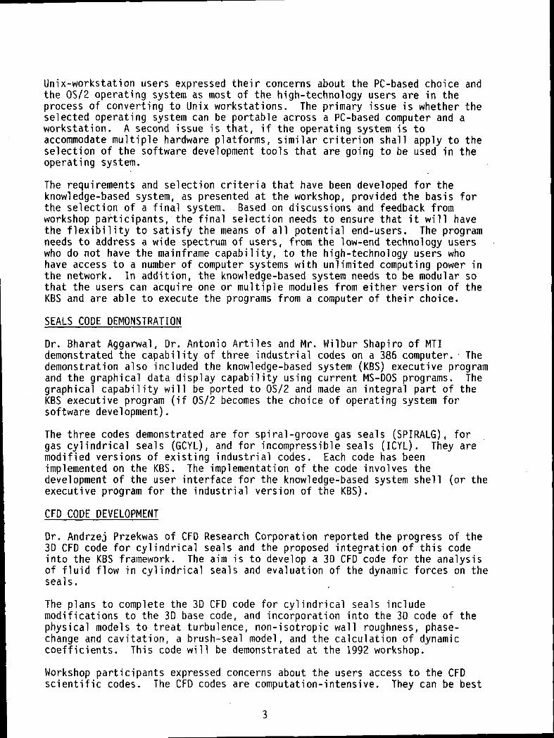
SEALS CODE DEMONSTRATION
Dr. Bharat Aggarwal, Dr. Antonio Artiles and Mr. Wilbur Shapiro of MTIdemonstrated the capability of three industrial codes on a 386 computer. Thedemonstration also included the knowledge-based system (KBS) executive programand the graphical data display capability using current MS-DOS programs. Thegraphical capability will be ported to OS/2 and made an integral part of theKBS executive program (if OS/2 becomes the choice of operating system forsoftware development).
The three codes demonstrated are for spiral-groove gas seals (SPIRALG), forgas cylindrical seals (GCYL), and for incompressible seals (ICYL). They aremodified versions of existing industrial codes. Each code has beenimplemented on the KBS. The implementation of the code involves thedevelopment of the user interface for the knowledge-based system shell (or theexecutive program for the industrial version of the KBS).
CFD CODE DEVELOPMENT
Dr. Andrzej Przekwas of CFD Research Corporation reported the progress of the3D CFD code for cylindrical seals and the proposed integration of this codeinto the KBS framework. The aim is to develop a 3D CFD code for the analysisof fluid flow in cylindrical seals and evaluation of the dynamic forces on theseals.
The plans to complete the 3D CFD code for cylindrical seals includemodifications to the 3D base code, and incorporation into the 3D code of thephysical models to treat turbulence, non-isotropic wall roughness, phase-change and cavitation, a brush-seal model, and the calculation of dynamiccoefficients. This code will be demonstrated at the 1992 workshop.
Workshop participants expressed concerns about the users access to the CFDscientific codes. The CFD codes are computation-intensive. They can be best

executed on a large capacity computer and/or through a network, with input andoutput communications provided from a desk-top system. Currently, the 3D CFDcode is being developed on an Al i i ant FX-8 computer with 256 megabytes ofcapacity. The approach is to eventually install the codes on the Cray andprovide the necessary linkage between the Cray and the desk-top system. Theconnection could be local, in the case of high-technology users, or remote,e.g. via a modem or through a network. The procedure for CFD code integrationand access will be presented at the 1992 workshop.
INDUSTRIAL INTERESTS
One of the purposes of the annual workshops is to provide interaction betweenthe user community and the code developers, thereby promoting the seal modelsfor practical applications. Close to twenty workshop participants presentedseals-related work in their organizations. Other participants expressedinterest in supplying test data for code verification and evaluation.Industrial support for this effort was evident and will be pursued as anintegral part of this program.
Several major activities are currently in progress in the community in thearea of brush seals. The advantage of the brush seal is its potential toreduce leakage. They are being investigated for rocket engine turbopumps, forsmall engine seals in the air flow systems, and for gas turbine engineapplications. Test data are being collected for each application to study theparameters affecting the performance of brush seals. These data canpotentially be used to evaluate the brush seal models that will soon bedeveloped in this program.
The industry is continuously interested in the use of the traditional shaftand face seals. Load models and analytical tools are under development forthese configurations to improve their performance. Suggestions were made byworkshop participants to obtain the analysis of alternate groove patterns tospiral grooves on face seals, to include mechanical face seals, to evaluatethe carbon face seal, and to provide means for predicting seal performance intwo-phase flow conditions. Buffered seals, rim seals, advanced counterrotating/ultra high pressure noncontacting seals, and gas seals for 3600 rpmrange were also among those recommended by workshop participants to beincluded in model evaluation.
One of the key items on the agenda for the 1992 workshop will be the issue oftechnology transfer. The users are anxious to acquire the codes that aredeveloped in this program, and exercise them on their own designs andproblems. Prompt technology transfer will provide benefits to the program intwo ways: 1. the codes will be evaluated by actual test data over practicaloperating conditions and become more valuable, and 2. the users will haveenhanced analytical capabilities and develop confidence in these codes for theanalysis and design of seals.
Typically, NASA sponsored software tools are released via COSMIC, the ComputerSoftware Management and Information Center operated by the University ofGeorgia for the Technology Utilization Office. In this program, the samemechanism will be used for the final release of the completed codes. In theinterim, a technology transfer plan will be developed prior to the 1992workshop to define a transfer-and-feedback mechanism for these codes so that

they can be released promptly to the user community for evaluation andverification prior to final delivery to COSMIC. The codes developed underthis program are targeted for a wide user community. Through an effectivetechnology transfer mechanism, they can be calibrated and become useful toolsfor commercial use.
Anita D. LiangWorkshop Chairman

INTRODUCTION
Anita D. LiangNASA Lewis Research Center
NASA Contract NAS3-25644, "Numerical/Analytical/Experimental Study of FluidDynamic Forces in Seals", was initiated in 1990 by the NASA Lewis ResearchCenter. It is a seven year program; the Mechanical Technology, Inc. (MTI) isthe prime contractor and CFDRC is the subcontractor. Annual workshops areincluded as part of the program to provide the interaction between the usercommunity and the contract team, and to disseminate, the codes that aredeveloped in this program to the potential end-users.
An introduction is made at the beginning of the first annual "Seals Flow CodeDevelopment" workshop to give the participants an overall description of theprogram. The program scope, the deliverables, the first-year accomplishmentsand the near term plans are presented.
Description of Contract, NAS3-25644Numerical/Analytical/Experimental Studyof Fluid Dynamic Forces in Seals
Program Status, Accomplishments and Plans
Workshop Objective
PRECEDING PAGE BLANK NOT FILMED

TEAM MEMBERS
NASA LeRC MTI CFDRC
Bob Hendricks Bharat Aggarwal Mahesh Athavale
Anita Liang Tony Artiles Andrzej Przekwas
Margaret Proctor Wilbur Shapiro Ashok Singhal
Julie Schlumberger
PROGRAM OBJECTIVE - Develop Codes for Analyzing and DesigningOptimized Advanced Seals for Future Aerospaceand Advanced Rocket Engine Systems
• DEVELOP 3-D CFD SCIENTIFIC CODES
• COMPILE AND GENERATE SETS OF VERIFIED 2-DINDUSTRIAL CODES
• GENERATE A KNOWLEDGE BASED SYSTEM (KBS) TO BECOUPLED TO THE CODES
8
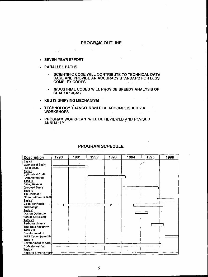
PROGRAM OUTLINE
• SEVEN YEAR EFFORT
. PARALLEL PATHS
- SCIENTIFIC CODE WILL CONTRIBUTE TO TECHNICAL DATABASE AND PROVIDE AN ACCURACY STANDARD FOR LESSCOMPLEX CODES
- INDUSTRIAL CODES WILL PROVIDE SPEEDY ANALYSIS OFSEAL DESIGNS
. KBS IS UNIFYING MECHANISM
. TECHNOLOGY TRANSFER WILL BE ACCOMPLISHED VIAWORKSHOPS
. PROGRAM WORKPLAN WILL BE REVIEWED AND REVISEDANNUALLY
PROGRAM SCHEDULE
DescriptionTasklCylindrical SealsCFD Code
Task IICylindrical Code
Task IIIFace, Wave, &Grooved SealsTask IVTip Contact &Non-continuous sealTask V
and DesignTask VI•» 1 ^ .i [ —
tlon of KBS SealsTasX VIITurbomachlneryTest Data FeedbackTask VIIIDevelopment ofKBS Code (Scientific
Task IXDevelopment of KBS
Task X
1990
i
1991 1992
p
i
1993
i-
1994
i
i
i
i
1995
1
r
i
czz
1996
ii
13
i
~\^

COMMON SCOPE OF CODE DEVELOPMENT TASKS
(TASKS I THROUGH IV, AND TASK IX)
LITERATURE SURVEY
CODE FORMULATION
OUTLINE FOR KBS INTEGRATION
PROGRAMMING AND CODING
VERIFICATION OF THE NUMERICAL ANALYSIS
CODE DOCUMENTATION
CODE INSTALLATION AND TECHNOLOGY TRANSFER
TASK V - CODE VERIFICATION AND DESIGN
CODE VERIFICATION
1. PUBLISHED LITERATURE
2. UNPUBLISHED INFORMATION FROM INDUSTRIAL SOURCES
3. CONSULTATION
DESIGN OF KBS CODES
10
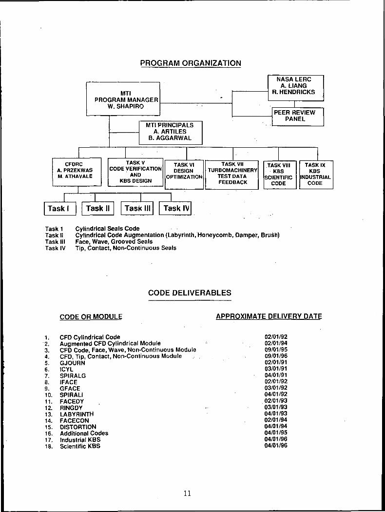
PROGRAM ORGANIZATION
MTIPROGRAM MANAGER
W. SHAPIRO
NASA LERCA. LIANG
R. HENDRICKS
MTI PRINCIPALSA. ARTILES
B. AGGARWAL
IPEER REVIEW
PANEL
CFDRCA. PRZEKWASM. ATHAVALE
TASKVCODE VERIFICATION
ANDKBS DESIGN
TASK VIDESIGN
OPTIMIZATION
TASK VIITURBOMACHINERY
TEST DATAFEEDBACK
TASK VIMKBS
SCIENTIFICCODE
TASK IXKBS
INDUSTRIALCODE
Task 1 Cylindrical Seals CodeTask II Cylindrical Code Augmentation (Labyrinth, Honeycomb, Damper, Brush)Task III Face, Wave, Grooved SealsTask IV Tip, Contact, Non-Continuous Seals
CODE DELIVERABLES
CODE OR MODULE APPROXIMATE DELIVERY DATE
1. CFD Cylindrical Code2. Augmented CFD Cylindrical Module3. CFD Code, Face, Wave, Non-Continuous Module4. CFD, Tip, Contact, Non-Continuous Module5. GJOURN6. ICYL7. SPIRALG8. IFACE9. GFACE10. SPIRALI11. FACEDY12. RINGDY13. LABYRINTH14. FACECON15. DISTORTION16. Additional Codes17. Industrial KBS18. Scientific KBS
02/01/9202/01/9409/01/9509/01/9602/01/9103/01/9104/01/9102/01/9203/01/9204/01/9202/01/9303/01/9304/01/9302/01/9404/01/9404/01/9504/01/9604/01/96
11

ACCOMPLISHMENTS
APPROVED THE BASE WORKPLAN
COMPLETED 3 INDUSTRIAL CODES
- ICYL- GCYL- SPIRALG (SPIRALGC + SPIRALGF)
COMPLETED FORMULATION OF THE KBSSTARTED INTEGRATION OF THE 3 CODES
DEVELOPED NEW AND MORE EFFICIENT ALGORITHMSFOR CFD ANALYSIS
FORMED THE PEER REVIEW PANEL
ORGANIZED THE 1ST ANNUAL WORKSHOP
SEALS CODE USER COMMUNITY
ROCKET ENGINE COMPANIES
GAS TURBINE MANUFACTURERS
SEAL COMPANIES
CONSULTANTS
GOVERNMENT AGENCIES
UNIVERSITIES
12

PEER REVIEW PANEL
GEORGE BACHE - AEROJET
TED BENJAMIN - NASA MSFC
DARA CHILDS/GERALD MORRISON - TEXAS A&M UNIVERSITY
RONALD DAYTON - U.S. AIR FORCE
HAROLD GREINER - EG&G
EUGENE JACKSON/JOE SCHARRER - ROCKWELL
ALAN LEBECK - MECHANICAL SEAL TECHNOLOGY
CHARLES MERKLE - PENN STATE UNIVERSITY
JOHN MINER/SAADAT SYED - PRATT & WHITNEY
JOHN MUNSON - ALLISON GAS TURBINE DIVISION
NELSON POPE - GENERAL ELECTRIC
RICHARD SALANT - GEORGIA INSTITUTE OF TECHNOLOGY
WORKSHOP RESULTS
NASA CONFERENCE PROCEEDINGS
- WORKSHOP PRESENTATION MATERIAL
- EXECUTIVE SUMMARY
UPDATED WORKPLAN
,- QUESTIONNAIRE
PEER REVIEW RECOMMENDATIONS
WORKSHOP DISCUSSIONS
13
NEXT YEAR'S WORKSHOP
UPDATED WORKPLAN
CYLINDRICAL CFD CODE
IFACE, GFACE, SPIRALI INDUSTRIAL CODES
FEEDBACK ON THE FIRST THREE CODES DELIVEREDIN 1991
TECHNOLOGY TRANSFER AND UTILIZATION PLAN
PRESENTATIONS BY PARTICIPANTS
14

N92-15083
INDUSTRIAL CODE DEVELOPMENT
W. ShapiroMechanical Technology Inc.
The industrial codes will consist of modules of 2-D and simplified 3-D or 1-Dcodes, intended for expeditious parametric studies, analysis and design of awide variety of seals. Integration into a unified system is accomplished bythe industrial KBS, which will also provide User Friendly interaction, contactsensitive and hypertext help, design guidance and an expandable database.
Major seal types include Cylindrical Seals and Face Seals, and within eachtype are a wide variety of configurations. For example, cylindrical sealsinclude uniform, step, taper, hydrostatic, segmented, damping, labyrinth, andspiral-groove configurations. More advanced types include brush seals,electro-fluids seals and smart seals.
The types of analyses to be included with the industrial codes are interfacialperformance (leakage, load, stiffness, friction losses, etc.), thermoelasticdistortions, and dynamic response to rotor excursions.
The first three codes to be completed and which are presently beingincorporated into the KBS are the compressible spiral-groove codes, SPIRALG,the incompressible cylindrical code, ICYL, and the compressible cylindricalcode, GCYL.
The spiral-groove codes analyzes both shaft seals and face seals with finiteeccentricity and misalignment. Four degrees of freedom are included forcylindrical seals, and three for face seals. The code predicts load, flow,power loss, and cross-coupled dynamic spring and damping coefficients, shaftdisplacements and minimum film thickness.
The ICYL (Incompressible Cylindrical Code) is a 2-D isoviscous code thatincludes roughness, multiple geometries (steps, pockets, tapers, preloadedaxes, and hydrostatic), turbulence, cavitation, and inertia at inlets to thefilm. Included are eccentricity and misalignment and variable gridspecifications. Specified pressure and periodic boundary conditions can beapplied. It produces pressures, flows, load, righting moments, filmthickness, power loss and cross-coupled dynamic spring and dampingcoefficients.
GCYL is a gas cylindrical code that can treat varying geometries (steps,tapers, hydrostatic, lobed, segmented). Shaft eccentricity, misalignment,specified boundary pressures or periodic boundary conditions can be applied.The program produces the clearance distribution, pressure distribution,leakage, load, moments, power loss and cross-coupled dynamic spring anddamping coefficients.
15
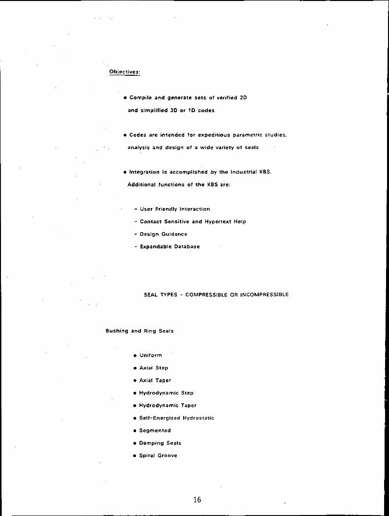
Objectives:
• Compile and generate sets of verified 20
and simplified 30 or 1D codes
• Codes are intended for expeditious parametric studies,
analysis and design of a wide variety of seals
• Integration is accomplished by the Industrial KBS.
Additional functions of the KBS are:
- User Friendly Interaction
- Contact Sensitive and Hypertext Help
- Design Guidance
- Expandable Database
SEAL TYPES - COMPRESSIBLE OR INCOMPRESSIBLE
Bushing and Ring Seals
• Uniform
• Axial Step
• Axial Taper
• Hydrodynamic Step
• Hydrodynamic Taper
• Self-Energized Hydrostatic
• Segmented
• Damping Seals
• Spiral Groove
16
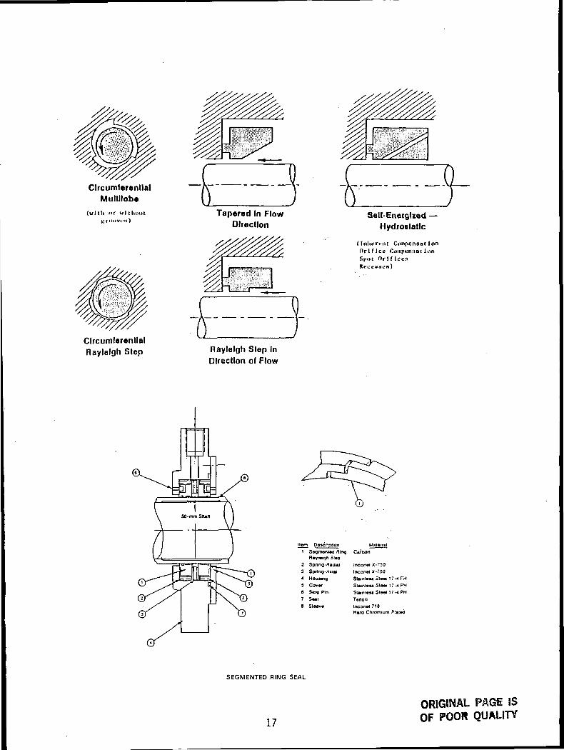
CircumferentialMutlllobe
(with or vrl thunt
CircumferentialRaylelgh Step
Tapered In FlowDirection
fj/S
Raytelgh Step InDirection of Flow
SeU-EnecgUed —Hydrostatic
(Inherent CompcnsatIonOr 1fIce CumpenHaiInnSpot Orlflcts
Item Deacnogon Maianal
3 Ring CarDon
2 Spnng-fl«3 Sprtng-Aji
4 Housing5 Cover
S Stop P!n
7 SMIfl Stew*
Incon* X-~50Inconrt X-750Stainlesa Ste«4 17-* FH
Stamleu Sleei 17-4 PHSlamfesj Steel 17-4PH
Teflon
Inconel 718Hard Chromium P!ated
SEGMENTED RING SEAL
17
ORIGINAL PAGt ISOF POOR QUALITY

i oxiirri f\.v*'-7 NMQIM *OrO«
AOTOMIXAOOCflATEO
DAMPING SEAL-LEAKAGE FLOW DAMPENS ROTOR MOTION;
ROUGH STATOR HINDERS ROTOR WHIRL
/ I i\.; H! IV ro-1- -
/ ^^ \I * \ \ u
SPIRAL-GROOVE
18

SEAL TYPES - COMPRESSIBLE OR INCOMPRESSIBLE
Face Seals
• Contact Face Seals
• Radial Step
• Radial Taper
• Hydrodynamic Step
• Hydrodynamic Taper
• Hydrostatic
• Spiral Groove
• Multi-pad
Hydrostatic CircumferentialRayleigh S'eo
CircumferentialTapered Land
Radial Rayleigh Step Radial Tapered Land
GFACE Configurations
19
ORIGINAL PAGfi FSOF POOR QUALITY
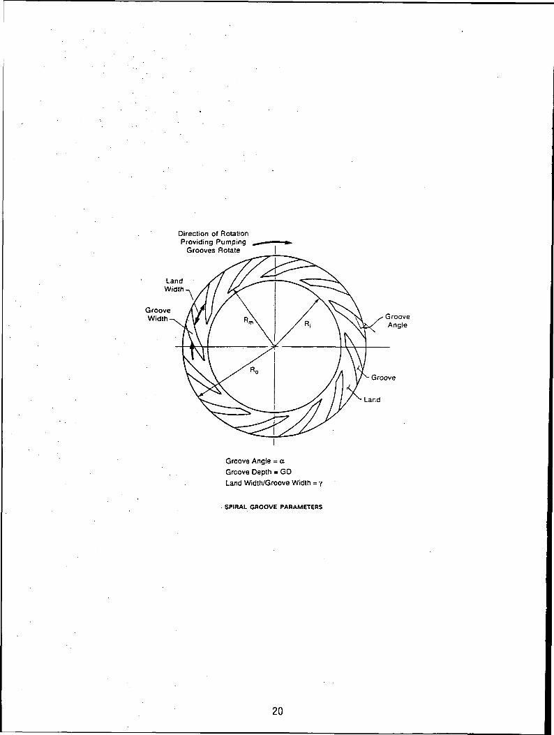
Direction of RotationProviding Pumping
Grooves Rotate
LandWidth
GrooveWidth
Groove Angle = a
Groove Depth = GD
Land Width/Groove Width = •/
SPIRAL GROOVE PARAMETERS
GrooveAngle
20
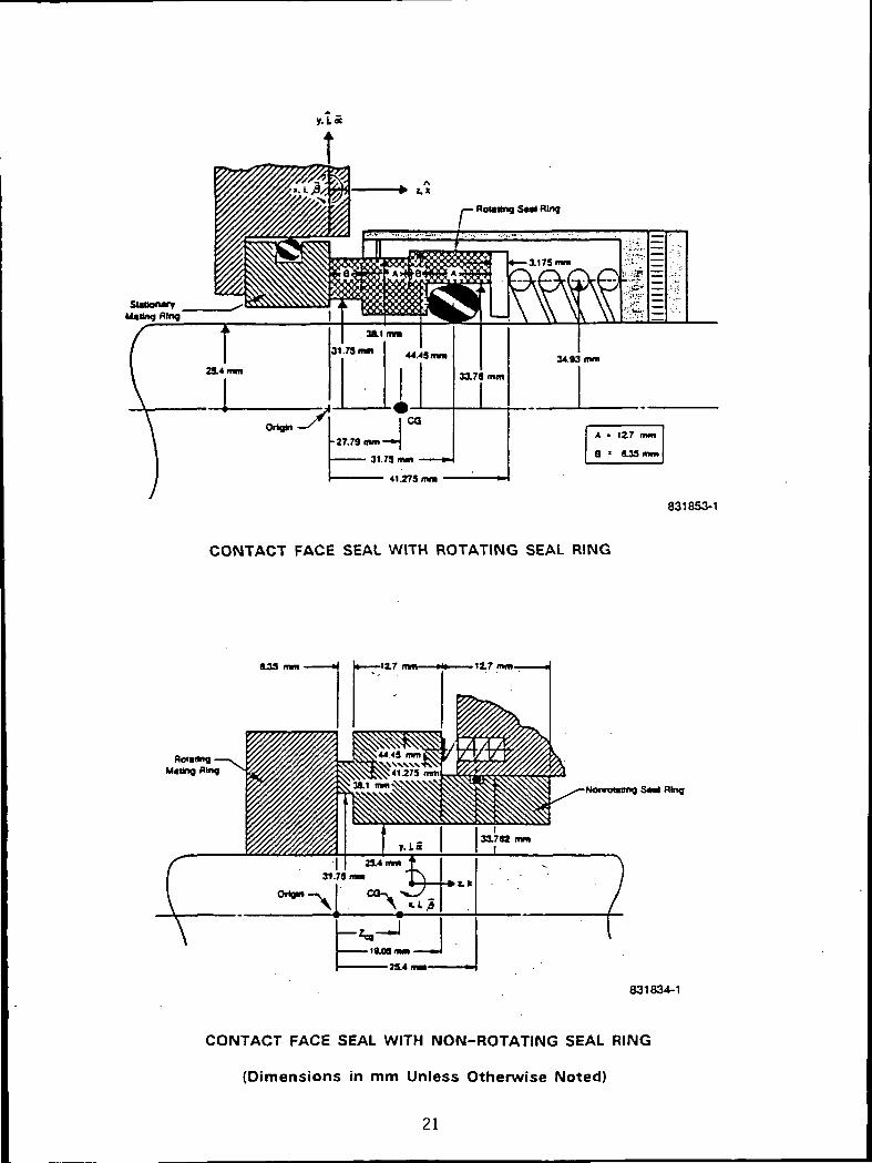
831853-1
CONTACT FACE SEAL WITH ROTATING SEAL RING
8-33 nun
\831834-1
CONTACT FACE SEAL WITH NON-ROTATING SEAL RING
(Dimensions in mm Unless Otherwise Noted)
21
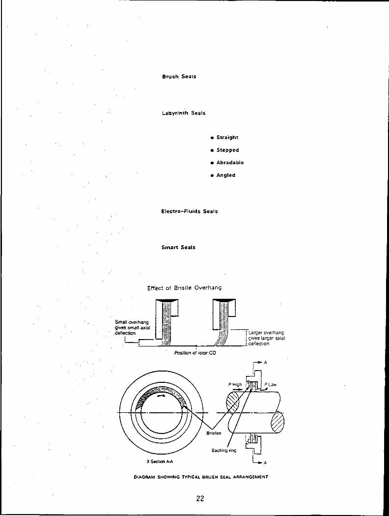
Brush Seals
Labyrinth Seals
• Straight
• Stepped
• Abradable
• Angled
Electro-Fluids Seals
Smart Seals
Effect of Bristle Overhang
Small overhanggives small axialdeflection
Position of rotor CD
I Larger overhangI gives larger axiai• ceflecticn
X Secion A-A
DIAGRAM SHOWING TYPICAL BRUSH SEAL ARRANGEMENT
22
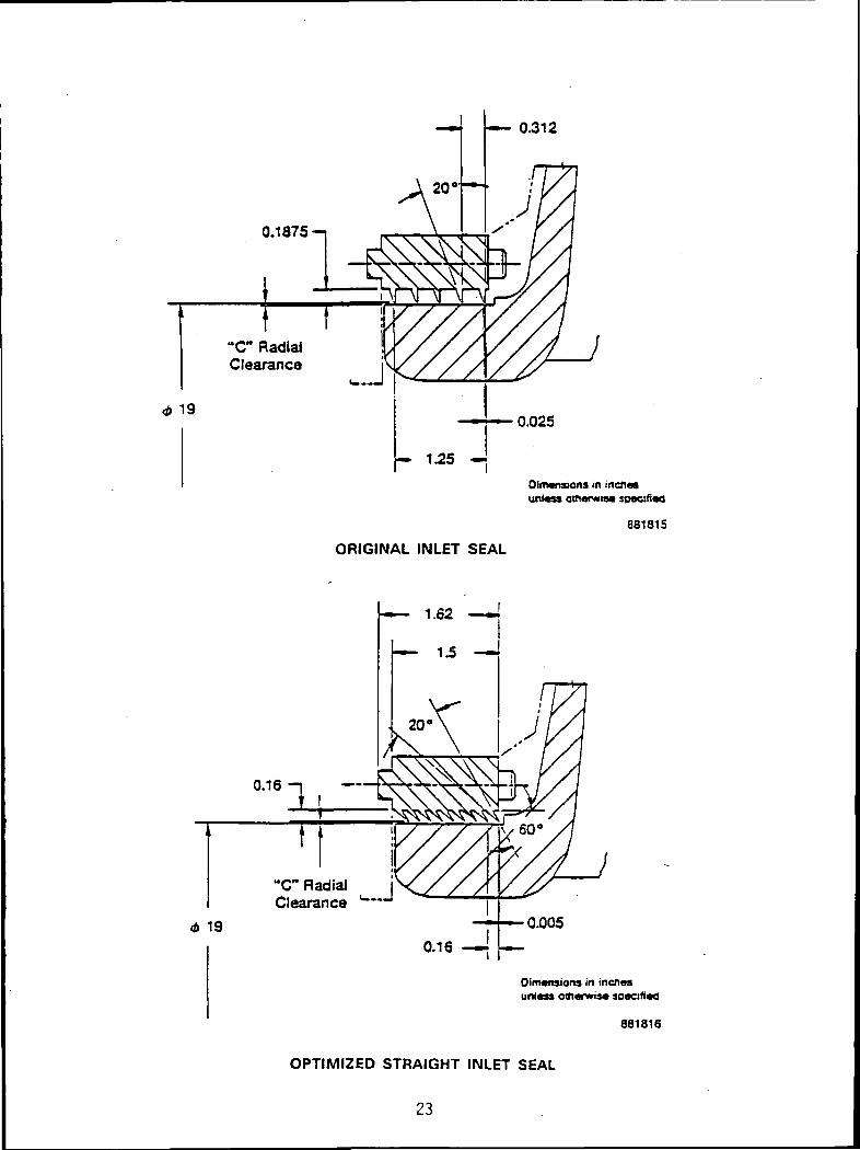
0.312
0.1875-1
"C" RadialClearance
<t> 19
Dimensions in incfiasuntess otnarMiaa so«ci(i«d
881815
ORIGINAL INLET SEAL
"C" RadialClearance
<t> 19 0.005
OinMfisiona in incnaaunless omanvis* aoecirtad
881816
OPTIMIZED STRAIGHT INLET SEAL
23

MAGNETIC FLUID SEAL
HIGH-SPEED POSITIONOF FLUID
(CENTRIFUGAL SEAL)HEAT EXCHANGERCOOLING WATER
ZERO OR SLOWSPEED POSITION
OF FLUID(MAGNETIC SEAL)
'LOW-PRESSUREREGION
NONMAGNETICMATERIAL
MAGNETIC MATERIAL,MAGNETIZED BYPERMANENT OR
ELECTROMAGNET
HIGH-PRESSUREREGION
ROTATING COLLAR
FUNDAMENTAL SEAL CONFIGURATION
Optimize Geometrylor Seal Performance
/ Inter! acialAnalysis
DynamicResponse
Determine K DynamicResponse is Acceptable
Determine if Distortionsare Excessive
ANALYTICAL TRIAD
24

Syilem Sup*ivl»k>n Coirpuler Progrim
LBuihlngModult
Face SaalModule
UbyrfcilhSaal
Module
DynamicModuli
T|p SaalModule
Thermo-alasllcModule
Damp! ngSeal
Module
MagneticFluid SealModule
Code Deliverables
Code Module Approximate Delivery Date
GCYL (Gas Cylindrical)
ICYL (Incompressible Cylindrical)
SPIRALG (Gas Spiral Groove)
CFD Cylindrical Code
IFACE (Incompressible Face)
GFACE (Gas Face)
SPIRALI (Incompressible-Spiral Groove)
FACEDY (Face-Dynamics)
RINCDY (Ring-Dynamics)
LABYRINTH (Gas)
Augmented CFD Cylindrical Module
FACECON (Face Contact)
DISTORTION (Thermo Elastic Distortion)
Additional Codes
e Brush
e Damping Seal
CFD Code, Face, Wave, Groove Module
Industrial KBS
Scientific KBS
CFD, Tip, Contact, Non-Continuous Module
02/01/91
03/01/91
04/01/91
02/01/92
02/01/92
03/01/92
04/01/92
02/01/93
03/01/93
04/01/93
02/01/94
02/01/94
04/01/94
04/01/95
09/01/95
04/01/96.
04/01/96
09/01/96
25
PLANNED ACTIVITY
i Code unification and completion
- Unified Grid Generator
- On-line Help
Code documentation
- Consistent with KBS usage
Additional problems and checkout
Annual report
26
2-15084DEVELOPMENT OF A CFD CODE FOR ANALYSIS OF
FLUID DYNAMIC FORCES IN SEALS
CFD Research CorporationM.M. Athavale, A.J. Przekwas and A.K. Singhal
This presentation is a status report for Task I of the Seals Flow Codeproject. The aim of this task is to develop a 3D CFD code for the analysis offluid flow in cylindrical seals and evaluation of the dynamic forces on theseals. This code is expected to serve as a scientific tool for detailed flowanalysis as well as a check for the accuracy of the 20 industrial codes
The features necessary in the CFD code are outlined. These include generalconsiderations such as code accuracy, efficiency, and robustness and otherspecific features such as rotating coordinate frames, steady and time-accuratesolutions, inclusion of non-isotropic wall roughness, effects of phase-changeand cavitation, and integration with KBS.
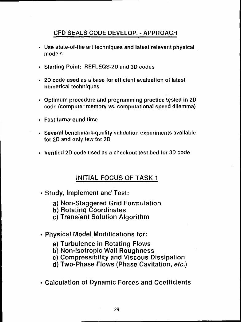
The approach and initial focus of the task is discussed next. The initialfocus of the task was to develop or modify and implement new techniques andphysical models. These include collocated grid formulation, rotatingcoordinate frames and moving grid formulation. Other advanced numericaltechniques include higher-order spatial and temporal differencing andefficient linear equation solver.
These techniques were implemented in a 2D flow solver for initial testing.Several benchmark test cases were computed using the 2D code and the resultsof these are compared with analytical solutions or experimental data to checkthe accuracy. Tests presented here include planar wedge flow, flow due to anenclosed rotor and flow in a 20 seal with a whirling rotor. Comparisonsbetween numerical and experimental results for an annular seal and a 7 cavitylabyrinth seal are also included.
The presentation is closed with plans for the second and final year of Task I.This involves completion of modifications in the 3D base code, andincorporation in the 3D code of the physical models to treat turbulence, non-isotropic wall roughness, phase-change and cavitation, brush-seal model, andcalculation of dynamic coefficients.
27

OBJECTIVES
• Develop Verified CFD Code for Analyzing Seals
• Required Features Include:
•• Applicability to a Wide Variety of Seal Configurations, suchas: Cylindrical, Labyrinth, Face, Tip and Brush Seals
•• Accuracy of Predicted Flow Fields and Dynamic Forces
•• Efficiency (Economy) of Numerical Solutions
•• Reliability (Verification) of Solutions
•• Ease-of-Use of the Code (Documentation, Training)
•• Integration with KBS
CFD CODE REQUIRED CAPABILITIES
Solve 2-D and 3-D Navier-Stokes Equations with Provisions for:
•• Complex Geometries (Body Fitted Coordinates, HighAspect Ratio Cells, Skewed Grids, etc.)
•• Stationary and Rotating Coordinates
•• Steady-State and Transient Analysis
•• Turbulence, Surface Roughness
•• Compressibility, Viscous Dissipation
•• Heat Transfer, Phase Change, Cavitation
•• Electromagnetic Effects, etc.
28
CFD SEALS CODE DEVELOP. - APPROACH
Use state-of-the art techniques and latest relevant physicalmodels
Starting Point: REFLEQS-2D and 3D codes
2D code used as a base for efficient evaluation of latestnumerical techniques
Optimum procedure and programming practice tested in 2Dcode (computer memory vs. computational speed dilemma)
Fast turnaround time
Several benchmark-quality validation experiments availablefor 20 and only few for 3D
Verified 2D code used as a checkout test bed for 3D code
INITIAL FOCUS OF TASK 1
Study, Implement and Test:
a) Non-Staggered Grid Formulationb) Rotating Coordinatesc) Transient Solution Algorithm
Physical Model Modifications for:a) Turbulence in Rotating Flowsb) Non-lsotropic Wall Roughnessc) Compressibility and Viscous Dissipationd) Two-Phase Flows (Phase Cavitation, etc.)
Calculation of Dynamic Forces and Coefficients
29
ADVANCED NUMERICAL TECHNIQUES - STATUS
Colocated Grid Formulation for BFC Grids
Strong Conservative Formulation of Momentum Equationswith Cartesian Components
Choice of SIMPLE, Modified SIMPLEC and Noniterative PISO
Higher Order Accurate Temporal Differencing
Higher Order (2nd, 3rd) Spatial Discretizations Available
Rotating Grid System for Stator-Rotor Configurations
Moving Grid option for Arbitrary Rotor Whirling Analysis
Efficient Multigrid Solver
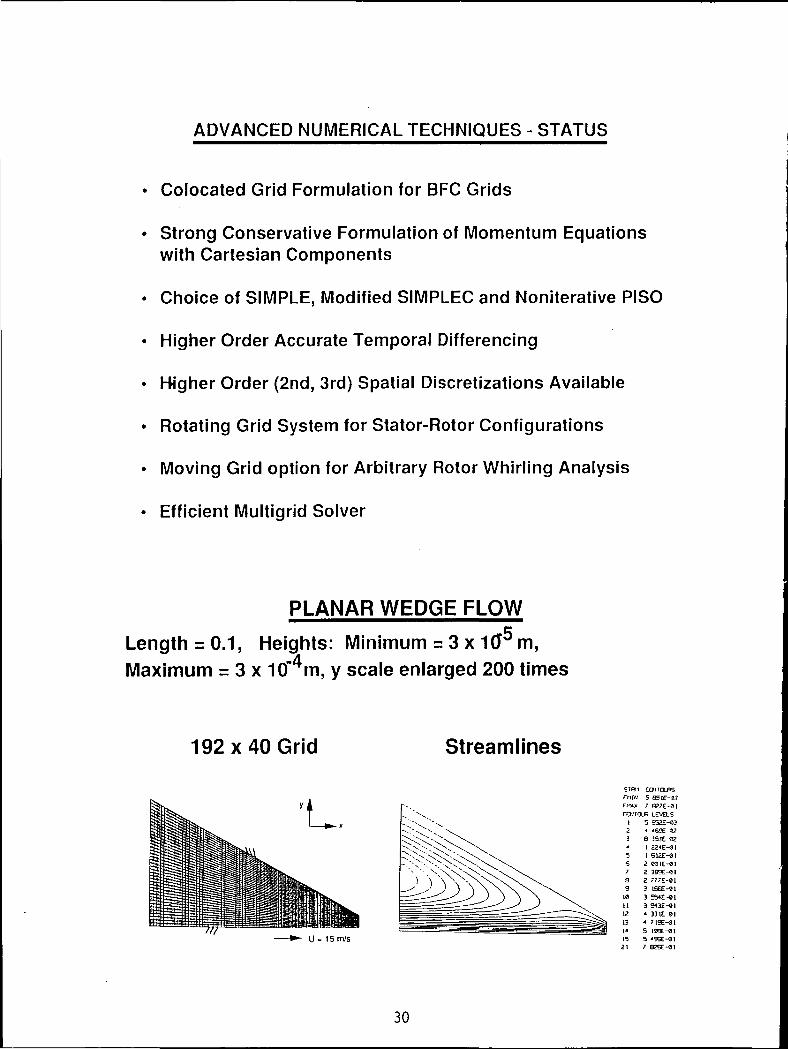
PLANAR WEDGE FLOW
Length = 0.1, Heights: Minimum = 3 x 10^ m,Maximum = 3 x 10"4m, y scale enlarged 200 times
192x40 Grid Streamlines
U •= 15 m/s
STPM CCWOLPS»1I« 5 851E-93FTOX 7 82/E-31CtWOP LEVELS
I 5 952E-032 « '59E-«23 8 353E-02
1 Sl2E-ei2 WlE-Ol2 385E-812 777E-313 16GE-013 554E-813 9<3E-91' 331E-814 719E-915 12QE-C1
7 82SE-9I
910I I1213141521
30

PLANAR WEDGE FLOW
u Velocity
D Analytical
— Numerical
x=0.5L x-0.751
Pressure
n Analytical
— Numerical
0 00 0 02 3 0-t 0 W5
ENCLOSED ROTOR
Daily & Nece (1960)
stator/rotor
31

ENCLOSED ROTORDaily and Nece
Tangential Velocity Radial Velocity
1 0-,
9 8-
Yanr
0 5-
3 4-
O 2-
r/b = 0.765
^^^^
D Data of Daily & NeceColocated Grid
oao 002 004 are arex/b
nr
-a os
r/b = 0.765
D Data of Dally & Nece—Colocated Grid
o 04 0 eex/b
WHIRLING ROTOR IN AN ANNULAR SEAL
Stator radius = 50.1478 x 10"3m,Clearance = 495 pm, e = 0.8 x clearance,Shaft Speed co = 5085 rpm
40 x 10 Computational Grid
FMIM -3 B83E'<!6rwx e I97E»«SCOlin n LE'/ELS
1 -J OTSE'06-2 512E»«S-2 035E»C6-1 551E»«6-1
Pressure ContoursSynchronous Whirl, Q = to
32ORIGINAL PAGE fSOF POOR QUALITY
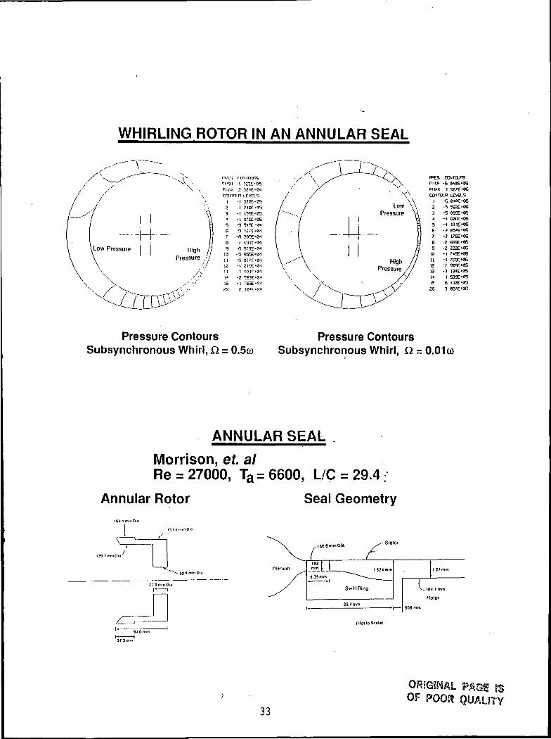
WHIRLING ROTOR IN AN ANNULAR SEAL
Cairo/is
FMAX 3 027E*«GCCNTOLR LEVELS
1 -S 04«C'CG2 -5 562E»«63 -5 C85E-«64 -4 «€6'C65 -4 I31E*«S6 -3 B54E'067 -3 176E'«66 -2 S93E>«69 -2 222E-«6
I I121314 1 63eE-«5
-1 266E««6
1521
Pressure Contours Pressure ContoursSubsynchronous Whirl, Q = O.Sco Subsynchronous Whirl, £1 = 0.01 co
ANNULAR SEAL
Morrison, et. alRe = 27000, Ta = 6600, L/C = 29.4
Annular Rotor Seal Geometry
L"M I
J^L L I _^^ 1 524 mm
Swirl Ring
25.4mm
1 27mm
V_i64 1 mm
RotOf
.SOS mm
{Mot loSc«!e|
33OF POOJf QUALJTY

ANNULAR SEAL
ux/U contours
Experimental Numerical
Inlet
25.2
1.05
1.050.95
29.2 25.3
x/cx/c
29.4
SEVEN CAVITY LABYRINTH SEAL
Morrison, et. al.Re = 28000 Ta = 7000
Labyrinth Rotor Inlet Geometry
t(lmm I 52* mmM
Ml
Cavity
?nd
CBvlty
3 (MB mm '
Close UP of Rotor
- I S < 1 mm
Hotor
34
ORIGINAL PAQfOF
QUALITY

SEVEN CAVITY LABYRINTH SEALVelocity Vector Plot
Experimental
First Cavity
Numerical
-• JCtCCCDCCCCCCDSCU^KCrCCCtEJ-
Third Cavity
\X
35
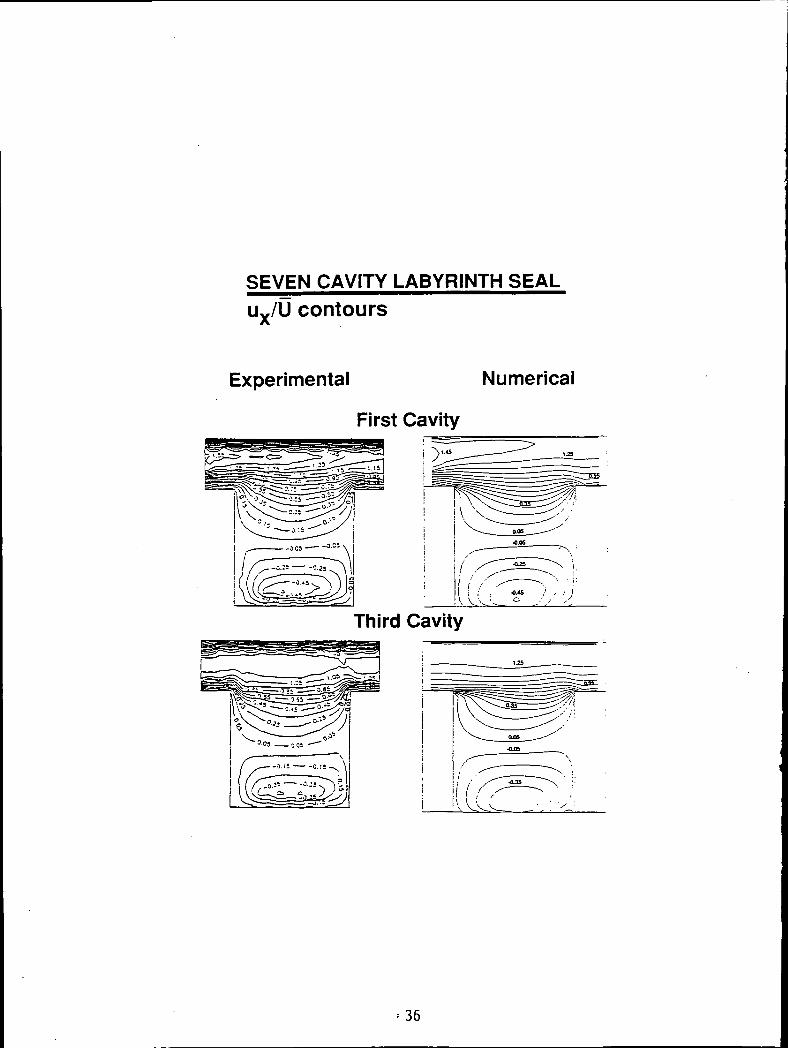
SEVEN CAVITY LABYRINTH SEALux/U contours
Experimental Numerical
First Cavity
Third Cavity
= 36

SEVEN CAVITY LABYRINTH SEALur/U contours
First Cavity/
0-05
t H.%^ m U s k*fol! I / = / ?.'»
I I?. .I \'
f^v-ys lU^a««JSli
.! si s| /
Third Cavity
SI . Slj'
.., «.•5: '9
37
ORIGINAL PAGE ISOF POOR QUALITY

SEVEN CAVITY LABYRINTH SEALue/wfehaft contours
Experimental Numerical
First Cavity
Third Cavity
-,,I • — * '
38
ORSGIWAL PAGf ISOF POOR QUALITY

TASK 1 COMPLETION PLAN (DEC 91)
• Complete Advanced Numerical TechniquesImplementation
• 3D Code Modifications
• Incorporation of Advanced Physical Models•• Turbulence Models
•• Non-lsotropic Wall Roughness
•• Compressibility and Viscous Dissipation
•• Two-Phase (Phase Change)
•• Cavitation
•• Brush Seal Model
• Incorporation of Dynamic Forces and Coefficients
39
2-15085
KBS DEVELOPMENT
Bharat AggarwalMechanical Technology Inc.
The KBS has two main objectives: 1) Provide easy access to all theindustrial and scientific codes through an executive program. The executiveprovides common services such as browsing and printing, direct access to aspecific code by clicking a button or selecting from a menu, and expert helpand guidance for seal analysis and design using expert systems to assist theuser. Other features of the KBS include online help and access to a databaseof test cases for the analysis codes. 2) Provide an easy to use userinterface for the analysis codes. The user interface is designed to minimizethe effort expended in dealing with the mechanics of using a computer,allowing the user to concentrate on seal design and analysis.
The KBS is implemented using the OS/2 Operating System with the PresentationManager (PM) graphical user interface. The PM environment provides supportfor windows, menus, buttons, etc. to enable design of a friendly userinterface. In addition, a rich set of functions are provided to support thedevelopment of interactive graphics applications. This facility will be usedto provide capabilities such as interactive seal layout and grid generation toreduce the volume of numeric input required by the programs. OS/2 currentlyruns on IBM PC compatibles using Intel 80286, 80386, or 80486 processors. IBMand Microsoft plan to port the system to run on some of the RISC platforms bythe end of 1992. The OS/2 Extended Edition from IBM also provides integratedcommunications and database support. These facilities will be usedextensively when the scientific codes are integrated into the KBS.
The user interface is designed to reduce the mechanics of using a computer tosimple operations such as menu selections, clicking buttons, etc. The basicoperations and menu items are consistent for all the programs to reduce thelearning time and to make the user feel comfortable when using the variousprograms. Context sensitive help is provided at all times and the user isprotected from making obvious errors. The data entry procedures are designedusing engineering terminology rather than computer jargon. The interactiveportions of the input are being designed to conform to the level ofabstraction used in the theoretical model so that the user does not waste timeand effort translating information on the screen into the concepts used tobuild the analytical model. The end result will be to have the interfacerecede into the background, leaving the user free to concentrate on sealdesign and analysis.
PRECEDING PAGE BLANK NOT FILMED41
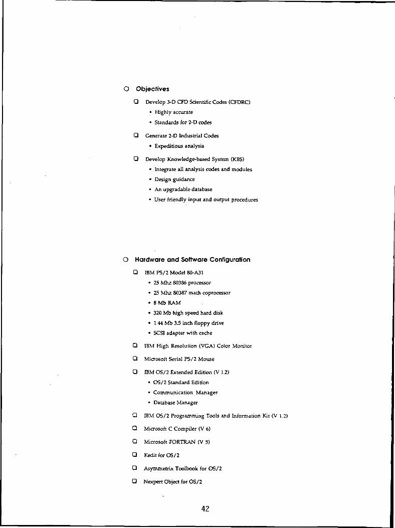
O Objectives
Q Develop 3-D CFD Scientific Codes (CFDRC)
• Highly accurate
• Standards for 2-D codes
Q Generate 2-D Industrial Codes
• Expeditious analysis
Q Develop Knowledge-based System (KBS)
• Integrate all analysis codes and modules
• Design guidance
• An upgradable database
• User friendly input and output procedures
O Hardware and Software Configuration
Q IBM PS/2 Model 80-A31
• 25 Mhz 80386 processor
• 25 Mhz 80387 math coprocessor
• 8Mb RAM
• 320 Mb high speed hard disk
• 1.44 Mb 3.5 inch floppy drive
• SCSI adapter with cache
Q IBM High Resolution (VGA) Color Monitor
Q Microsoft Serial PS/2 Mouse
Q IBM OS/2 Extended Edition (V 1.2)
• OS/2 Standard Edition
• Communication Manager
• Database Manager
Q IBM OS/2 Programming Tools and Information Kit (V 1.2)
Q Microsoft C Compiler (V 6)
Q Microsoft FORTRAN (V 5)
Q Kedit for OS/2
Q Asymmetrix Toolbook for OS/2
Q Nexpert Object for OS/2
42
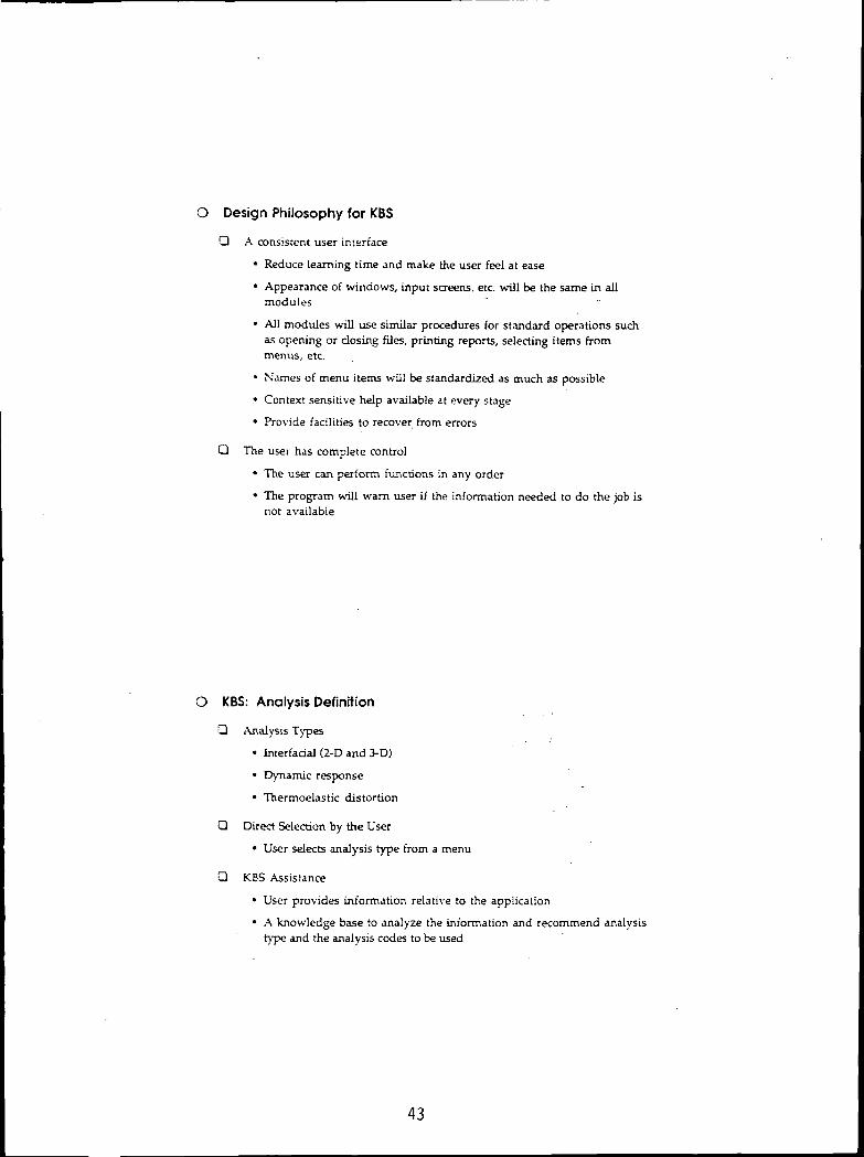
O Design Philosophy for KBS
Q A consistent user interface
• Reduce learning time and make the user fee! at ease
• Appearance of windows, input screens, etc. will be the same in allmodules
• All modules will use similar procedures for standard operations suchas opening or dosing files, printing reports, selecting items frommenus, etc.
• Names of menu items will be standardized as much as possible
• Context sensitive help available at every stage
• Provide facilities to recover from errors
Q The user has complete control
• The user can perform functions in any order
• The program will warn user if the information needed to do the job isnot available
O KBS: Analysis Definition
Q Analysis Types
• Interfacial (2-D and 3-D)
• Dynamic response
• Thermoelastic distortion
Q Direct Selection by the User
• User selects analysis type from a menu
O KBS Assistance
• User provides information relative to the application
• A knowledge base to analyze the information and recommend analysistype and the analysis codes to be used
43

O KBS: Design Guidance and Optimization
Q Guide iterative analysis
• Optimization is an iterative process involving interfacial analysis,dynamic analysis, and thermoelastic analysis
• Analyze output data to determine if iterations should continue
• Recommend the analysis to run in the next iteration
• Recommend the parameters to be changed in the next iteration
O KBS: Databases
Q Data to be Archived
• User Input data sets
• User Output data sets
• Data sets used in code validation
Q Database Procedures
• OS/2 Extended Edition Database Manager used for storing andretrieving data
• Networked database support provided through OS/2 facilities
• Data entry and retrieval screens will be designed using the QueryManager and SQL compatible commands
• Password protection will be provided to prevent unauthorized access
44

O KBS: Help and Guidance
Q Implementation
• Hypertext capabilities of Toolbook and the Information PresentationFacility (IFF) included with OS/2 will be used to design the help system
• Graphics and text will be mixed as needed
• Context sensitive help
Q Help: General
• User Interface
Q Help: Each Analysis Module
• Purpose
• Capabilities and limitations
• Theoretical background
• References
• Code validation procedures
• Description of input and output variables
• Example problems with sample input and output
Q Guidance
• Design procedures
• Seal type recommendations
O KBS: Menu Structure
CFD Codes - Main MenuScientific Codes
Analysis DefinitionSeal SelectionDatabase OperationsDesign GuidanceHelpQuit
™™. ^ „,„,_,1 r
45

Spiral.exe - Spiral Groove Gas SealsFile Input Validate Output Help
Output File:
Input File:
CFO Industrial Codes: Spiral Groove Gas Seals
Spiral.exe - Spiral Groove Gas Seals
Grid Definition
-Seal Configuration
l Region
<S> 2 RegionsO 3 Regions
Number of Cicumferential Grid Intervals
Relative Size
Grid Intervals
Groove/Pitch Ratio
Groove Angle [Deal
Groove Depth (in)
-46

2-15086KBS Demonstration
B. Aggarwal, A. Artiles, and W. ShapiroMechanical Technology, Inc.
The demonstration included five different items; the executive program, threeof the industrial codes, and graphical data display capability using currentMTI MS-DOS programs. The graphics capability included two- and three-dimensional plots viewed from different angles. This capability will beported to OS/2 and made an integral part of the KBS executive program.
The executive program has a button for each industrial code and facilities toprint and browse input and output files generated by the analysis codes. Theplotting capability will be added in the future. The user can start any ofthe codes by clicking on the button for the code. The number of codes runningsimultaneously is limited only by the amount of memory available on themachine. Multitasking capabilities of OS/2 are exploited to perform printing,browsing and analysis functions in parallel.
The three codes demonstrated included Spiral Groove Gas Seals (SPIRAL), GasCylindrical Seals (GCYL) and Incompressible Seals (ICYL). SPIRAL and GCYLinterface has the standard PM interface while ICYL interface was designedusing ToolBook.
SPIRAL and GCYL have pull down menus to access input screens. The names ofthe menu items are the same in both programs. Program options area chosenusing radio buttons and check boxes instead of entering numbers. Entry fieldsfor numeric information have built in checks to ensure that the numbers arewithin acceptable ranges. Context sensitive help is provided for all input.When the input is complete, the user may start the analysis by clicking on theanalyze button in the menu bar. The output is stored in a use specifiedoutput file. The user may also elect to save the input data is a file forfuture use.
Interactive graphics have been used to ease the input process. In SPIRAL, theuser can get immediate feedback during analysis grid specification by clickingon the DRAW button. The program will display the grid as currently specified.In GYCL, the layout of features such as Rayleigh Steps, Recesses, fluidsources, etc. on seal pads is done interactively. The components are laid outon the specified grid using the mouse. This provides a visual representationof the seal pad and avoids having to input a large volume of numerical data.This capability will be extended to include variable grid specification.
ICYL interface shows an alternative approach. The menu items are laid out onthe screen in the traditional manner. Submenus appear cascaded on the samescreen when a menu item is selected by clicking on it. The concept is similarto the pulldown menus of the standard PM interface. Direct access is providedto any input screen from any other input screen. Menu item names are the sameas in SPIRAL and GCYL. Program options and numeric data input procedures arethe same as in SPIRAL and GCYL. Arrays of numbers are input using scrollableentry fields. This capability will be added to SPIRAL and GCYL.
47

SPIRAL-GROOVE CODE
Dr. Jed Walowit
Stator for Spiral Grooved Face Seal
48

Spiral Grooved Gas Seal Computer Codes
• Shaft seals and face seals
• Compressible flow
• Finite eccentricity and misalignment
• Four degrees of freedom for shaft seals (three for face seals)
• Frequency dependent dynamic coefficients
• Arbitrary end pressures
• Predicts load, flow, power loss, dynamic coefficients, shaft
displacements and minimum film thickness
ICYL (Incompressible Cylindrical Seals) Code
Dr. Antonio Artiles
MTI
49

PROGRAM ICYL
CAPABILITIES
• 2-D incompressible isoviscous flow in
cylindrical geometry
• Rotation of both rotor and housing
• Roughness of both rotor and housing
• Arbitrary film thickness distribution,
including:
- Steps, pockets, tapers
- Preloaded arcs
• Rotor position and velocity is described
by four degrees of freedom
(translational and rotational)
• External forces and moments may be prescribed
to find rotor position
• Pocket pressurs or orifice size are prescribed
• Laminar or turbulent flow
• Cavitation
• Inertia pressure drop at inlets to fluid film
- From ends of seal
- From pressurized pockets
50

Computer Code GCYL
(Gas Cylindrical Code)
Wilbur Shapiro
MTI
51

Computer Code GCYL
The general capabilities of the GCYL include:
• Varying geometries
• Variable or constant grid (30 x 74)
• Shaft eccentricity and misalignment
• Specified boundary pressures and periodic
boundary conditions
• Symmetry in axial direction
• Determining load (function of displacement)
or seal position to satisfy given load
• Choice of English or SI units.
The output of the program include:
• Clearance distribution
• Pressure distribution
• Leakage at specified flow paths
• Load and load angle
• Righting moments
• Viscous dissipation
• Cross-coupled, frequency-dependent,
stiffness and damping coefficients
• Plotting routines (pressure and clearance
distribution)
52

N92-15087
SEALS RELATED RESEARCH AT LEWIS RESEARCH CENTER
R. C. HendricksNASA Lewis Research Center
Cleveland, Ohio
Lewis Research Center has a strong history supporting seals, and sealdynamics, research design, design, fabrication and test. Some efforts includespiral groove, self energized configurations, Rayleigh lift pads, conical,labyrinth, bore, honeycomb, face, tip, support for two-phase work, steppedconfigurations for SSME, near critical expansion, visualization, dynamicanalyses, and materials.
Some researchers on these topics include: Larry Ludwig and Bob Johnson'svarious seal designs and application; John Zuk's cavity analysis and sealscodes; Tom Strom's face and spiral groove seals; Dave Fleming's variousconfigurations including conical seals and dynamic stability predictions; BobBill's abradable and ceramic configurations; Bill Hughes' two-phase flowanalyses; Hal Sliney's materials work; Gordon Alen, Bill Loomis, El Dirussoand Bill Hady's test data comparisons and analyses; Isaaic Etsion's analysesof a variety of configurations; Allen Lubeck's face and shaft seal analyses;Hendricks1 shuttle seal and multiple aperture configuration research; GlenMcDonald and Hendricks1 ceramic shroud seal; and the Texas A&M program to citesome of LeRC's efforts.
Some current efforts include: Bruce Steinetz and Paul Sirocky's self sealinglinear segmented ceramic configurations; George Bobula, Bob Bill andHendricks1 T700 brush seal engine test; flow and duration characteristics ofbrush seals and other configurations with Margaret Proctor and JulieSchlumberger; cryogenic hydrogen brush seal tests at Rocketdyne with JoeScharrer; Teledyne brush seal tester with USAF; and support for contracts andgrants.
53

.
7////////S/////////V/^^^^
DETAINER RING-. — CARSON RING
SELF-ACTING PAD LOCATION.
MOTION VIEWA-A >FEED GROOVE
~'%,tX.7777-77777} I
0.0025 CM
(0.001 IN. )
VIEW B-B
54

LABYRINTH SEAL
COMPRESSORPRESSURE
SUMPPRESSUREP
55

1.6
1.2
e:o
= -8
.4
.. . 4 SubcooledReduced inlet ,- jd .
stagnation 3 ^temperature.
TR.O0.75
Saturation^region
0 .4 .8 1.2 1.6 2.0
Reduced inlet stagnation pressure. PR 0
Reduced choked mass flux based on homogeneous isentropic equilbrium model.
andArCH4
Reduced inletstagnation
temperature.TR.O0.8
Also Ar
.5 1.0 1.5 2.0 2,5Reduced inlet stagnation pressure. PR 0
3.0
Critical mass fluxes of oxygen, nitrogen, argon, and methane computed by isentropic equilibrium expansion using corresponding-states principles.
56
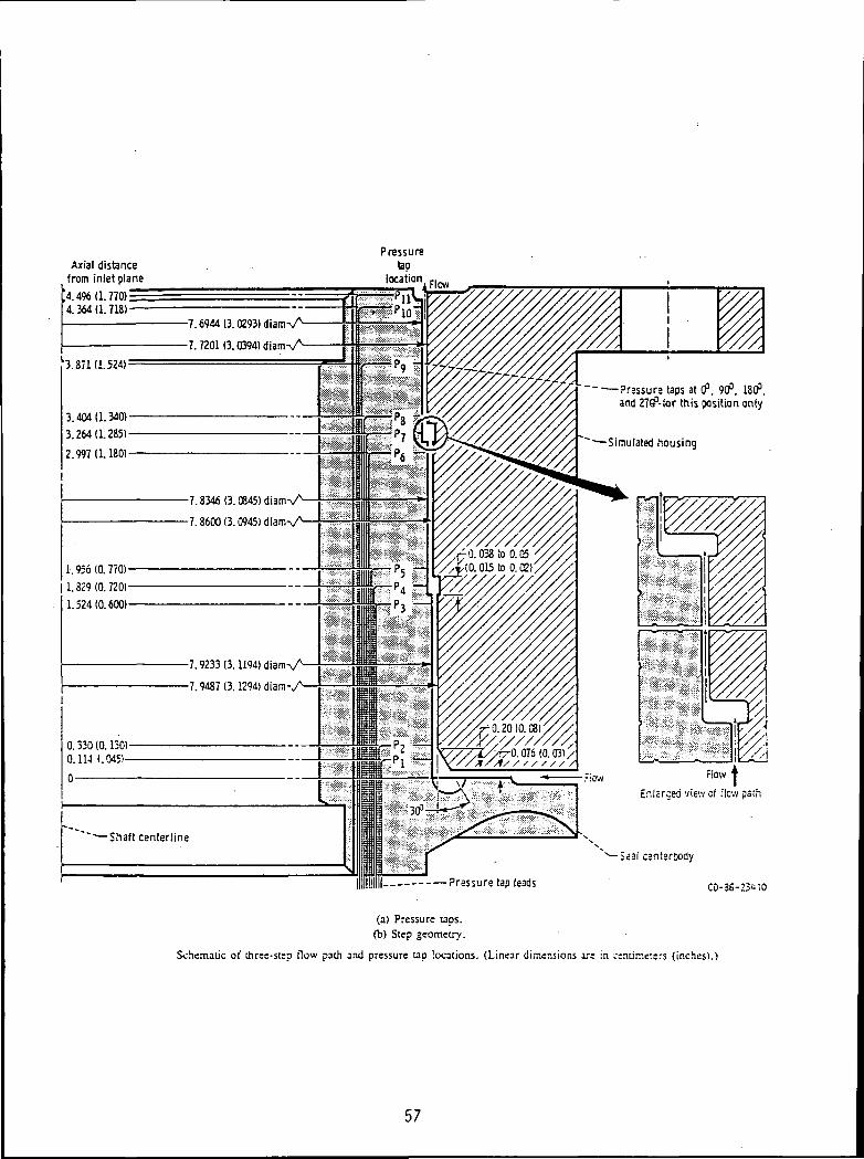
Axial distancefrom inlet plane
>. 4% (1.770)==4.364(1.718)
3.371 (1.524) =
3.404(1.3401-3.264(1.2851-2.997(1.1801-
I
1.956(0.7701-
11.829(0.7201-
1.524(0.6001-
0.330(0.1301-0.114 (.0451-
-7.6944(3.0293)diamV^
-7.7201 (3.0394) diam Vs
-7.8346(3.C845)diamVN
-7.8600 (3.
-7.9233 (3.1194) diam V^
-7.9487(3.1294) di
"—Shaft centerline
-—Pressure taps at 0°, 90°. 180°,and 27ff'-for this position only
Simulated housing
Flow
Enlsrced view of flow path
Seal canter&ody
— Pressure tap leads CD-36-23110
(a) Pressure taps,fb) Step geometry.
Schematic of three-step flow path and pressure tap locations. (Linear dimensions ire in centimeters (inches).1
57

xial distancefrom inlet planes:
' 4.724 (1.860)4.623(1.820)=4.496(1.770)
'3.998(1.574):
3.391(1.:
1.956 (0.770)-
0.457 (0.180)-0.330(0.130)-
-S.42<ii(3.3167)diam-v^
-8.4513 (3.3273) diam-%A
~~-—Shaft centerline
Pressuretap
location:
•P6 —
-PS- P5j- P5k~
-P4'
"Radial clearance,/' 0.01346 (0.0053) /
Flow
"^Simulated housing
0.1346(0.00531-
Pressure
tap PI-^ ^
0.081 V10.032) ~] |\
1 L0.330 A
(0.130)
0.290(0.114)J L
y 0.005 i
Enlarged view of inlet(data snow tap PQ tofunction as a totalpressure tap)
Flow
-Seal center&ody
Pressure tap leads
Overview of pressure taps and geometry for straight cylindrical seal. -(Linear-dimensions'are in- centimeters (inches).')
58
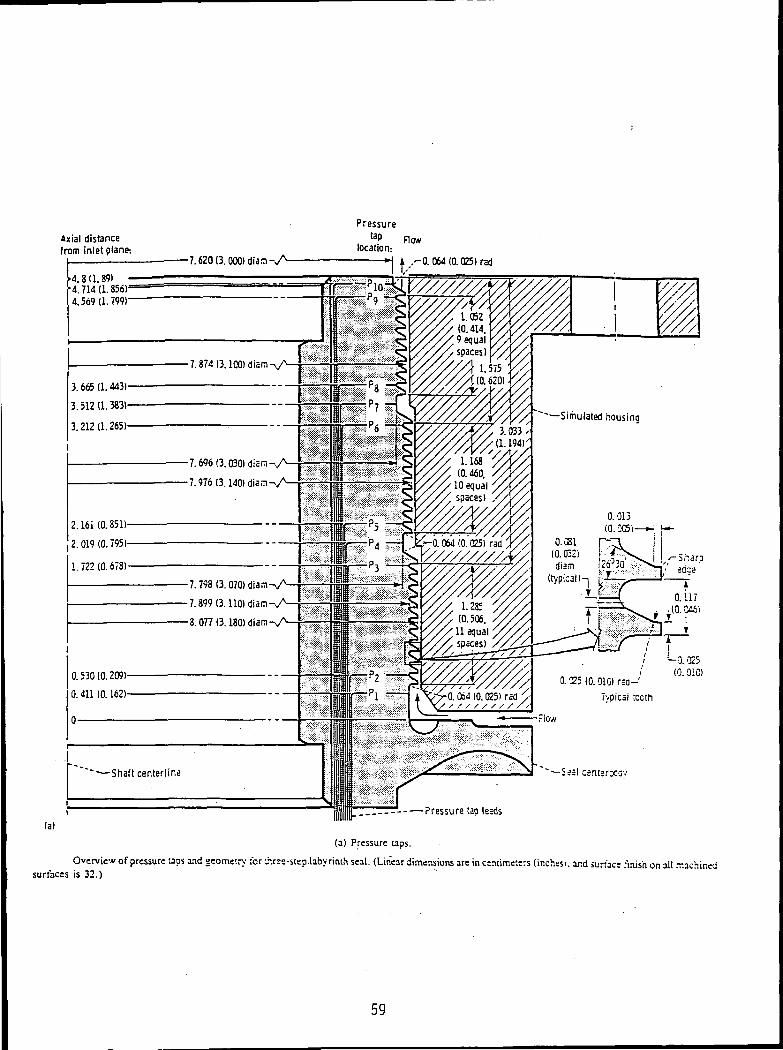
Axial distancefrom inlet plane:
-7.620(3.000)diam-vA
Pressureta.P Row
location:
(a)
."0.064 (0.025) rad
4.8(1.89)4.714(1.856)4.569(1.799)
7.874(3.100) diam
3.665 (1.443)
3.512(1.383)
3.212(1.265)Simulated housina
7.696 (3.
7.976(3.
2.161(0.851)
2.019 (0.795) ~Q. 064(0.' 025) rad Y//
7.798(3.070)diarn-v^
0.530 (0.209)
0.411 (0.162)0.025 (0.010) rsa-'
Typical teeth/Xd.0b4(b.'o25)'radv
'-—Shaft centerline ~—Seal csntsrxcv
Pressure tap leads
(a) Pressure QDS.
Overview of pressure taps and geometry ;br uHree-step.labyriiuh seal. (Linear dimensions are in ctniimeters (inches), and surrac: finish on all machinedsurfaces is 32.)
59

.25
.20
O)
= .10
.05
0
Reducedinlet
stagnationtemperature,
TR.O
.5 1.0 1.5Reduced inlet stagnation pressure. PR 0
2.0
Reduced mass flux of fluid nitrogen through three-step labyrinth seal in concentric position, as function of reduced inle: stagnation rressure.
.6
.4
.2
Reducedinlet
stagnationtemperature,
TR.OO 0.68D .86A 1.0 to 0.94O 1-12p Gaseous nitrogen, 4/19/77V Gaseous nitrogen, 4/20/77
0 .5 1.0 1.5Reduced inlet stagnation pressure, PR 0
Reduced mass flux of fluid nitrogen through three-step cylindrical seal in fully eccentric position, as function of reduced inlet stagnation pressure.
60
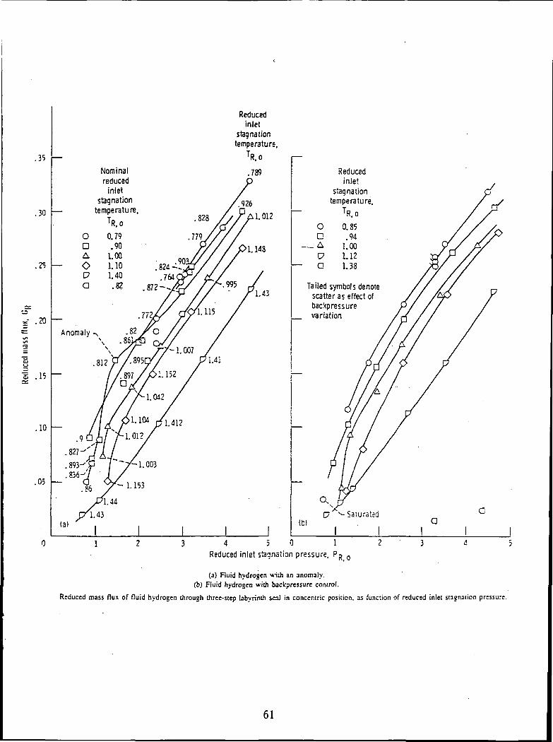
.35
Reducedinlet
stagnationtemperature,
TR.O
.30
.25
Nominalreduced
inletstagnation
temperature.1.012
*- .20
s .15
.10
.05
OnAVa
Reducedinlet
stagnationtemperature,
TR.O0.85.94
1.001.121.38
Tailed symbols denotescatter as effect ofbackpressurevariation
(b)G
1 2 3 4 5 0 1 2 3 4 :Reduced inlet stagnation pressure, PR 0
(a) Fluid hydrogen u-ith an anomaly,(b) Fluid hydrogen with backpressure control.
Reduced mass flux of fluid hydrogen through three-step labyrinth seal in concentric position, as funciion of reduced inlet stagnation pressure.
61

62

. j -oog t' c
I-( ifj-J5
p o> W 5TB 5*ytoo f.< J.
_3o_ £ .s ;J .
Ill I-•i i
n"
• 17.5
,.8rf'TW-t IIAf
I pr QljE. £c£Ml>/r
63
ORIGINAL PAGf fSOF POOR QUALITY

i'r «
ill ir ",~\
•^ !
PRESSURE DROP ACROSS BRUSH VERSUS MASS FLOWRATE
(IN LIQUID NITROGEN)/u
60
Crt .
S*3ni oU
D on*•* <iU
i(J
r» -^
• AA
• .*/
A"A •
'• A"
A" !A A
^ A •
A
• A•
. i
0.005 0.01 0.015 .0.02
MASS FLOW RATE, Ibm/s/in-circ.
0.025
• 0 RPMA 400 RPM
64ORIGINAL PAGE !SOF POOR QUALITY

120-
o..clOO
I»
S 80o5 70
£60
5 40
I »-
20-
10
o -o.<
-.0035 In. clearance /•*
/ tfm 2 uo-/' ^« o.' °^ jT 100
/ °" i so• o° S 80
0 S 70.4° <
/ 0 " 0 - 6 0 -
/ °"' ^ 5°-! «•
/ c. S 30-
' £" 2°/« 10'
.
-.0019 In. clearanc* f c
0* '• ^
,0 •
.c*
. -•' c
, . o 0 *A-- n •
/ *° "
•^V°")0 . 0 .05 0.10 0.15 0.20 0.25 0.30 fl.OO 0.05 0.10 0.15 0.20 0.2J 0.2
Volumetric Flowrate, SCF/s Volumetric Flowrate, SCF/s
120
2110
j-I xa« 80
1"
I"Q 50c3 40«
« 30C.
20
10
0a
-.0003 In. clearance 120'
CD * I"0'
• £ 100 -
• * J S0"
, /^u "* S 80
XT** 0 70
/•V " | SO
•& " ^50
• ./* | 40
/^p • ^ 30
X* 0*. 20
.0014 in. clearance
o»c
; •
>-^./""'
.-• a *A ^
/ 10 .'' « •
X -« 1 " i*r-<^ '
.00 0.05 0.10 0.15 0.20 0.25 0.30 °-°° °-05 °-10 "-15 0.20 0.2: 0.:
Volumetric Flowrate, SCF/s Volumetric Flowrate, SCF/s
• . D 0 rpm• •0 4CO rpm
SOLID-UPiNPRESUREOPEN • DOWN IN PRESSURE
~J* — theoretical
COMPARISON OF DATA AT 0 AND 400 RPM WITHOUT FLOW STRAIGHTENER
65

N92-15088
MSFC HYDROSTATIC BEARING ACTIVITIES
Theodore G. BenjaminComputational Fluid Dynamics Branch
Aerophysics DivisionStructures and Dynamics Laboratory
George C. Marshall Space Flight Center
The basic approach for analyzing hydrostatic bearing flows at MSFC isthree pronged. First, the Hydrostatic Bearing Team has responsibility forassessing and evaluating flow codes, evaluating friction, ignition, andgalling effects, evaluating wear, and performing tests. Secondly, the Officeof Aerospace and Exploration Technology Turbomachinery Seals Tasks consist oftests and analyses. Thirdly, MSFC in-house analyses utilize one-dimensionalbulk-flow codes; computational fluid dynamics (CFD) analysis is used toenhance understanding of bearing flow physics or to perform parametricanalyses that are outside the bulk-flow data base. As long as the bulk-flowcodes are accurate enough for most needs, they will be utilized accordinglyand will be supported by CFD analysis on an as-needed basis.
Overview
Hydrostatic Bearing Team formed 02/16/90- Assess and validate flow codes- Evaluate friction and ignition effects- Evaluate wear and galling effects- Verify design by HPOTP pump-end test (Rocketdyne IRAD)
- TTB in October / November timeframe
OAET Turbomachinery Seals Tasks- Three tasks in place - - E3b, E4e, and LSVT13- One task pending - - LSVT8 (NRA)
In-house CFD analyses- Baseline damping seal
- Code validation- Rotordynamic coefficients
- Baseline hydrostatic seal- Flow cavity parameters- Flow visualization
PRECEDING PAGE BLANK NOT FILMEDD/
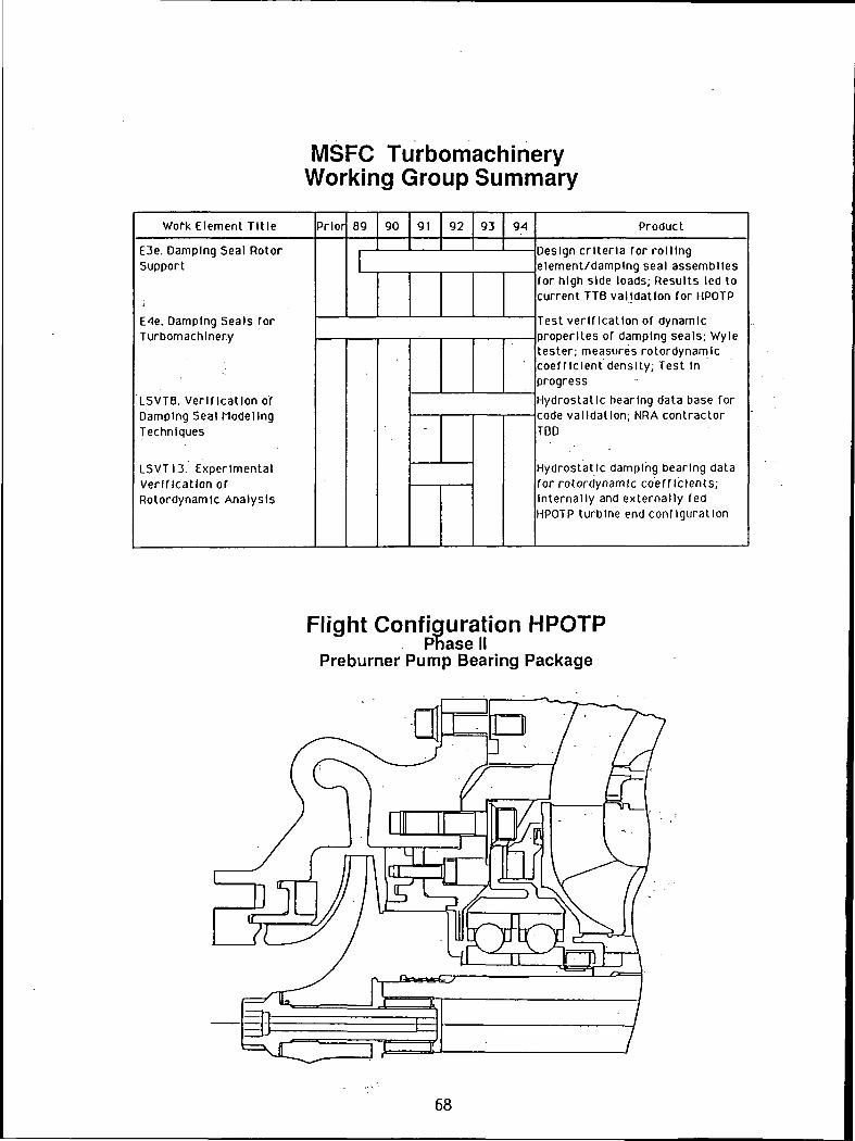
MSFC TurbomachineryWorking Group Summary
Work Element Tit le Prior 89 90 91 92 93 Product
E3e. Damping Seal RotorSupport
E4e. Damping Seals forTurbomachinery
LSVT8. Verification ofDamping Seal ModelingTechniques
LSVTI3. ExperimentalVerification ofRotordynamlc Analysis
Design criteria for rollingelement/damping seal assembliesfor high side loads; Results led tocurrent TTB validation for HPOTP
Test verification of dynamicproperltes of damping seals; Wyletester; measures rotordynamlccoeff icient density; Test Inprogress
Hydrostatic bearing data base forcode validation; NRA contractorTBD
Hydrostatic damping bearing datafor rotordynamlc coefficients;Internally and externally fedHPOTP turbine end configuration
Flight Configuration HPOTPPhase II
Preburner Pump Bearing Package
68

HPOTP Pump End RetrofitAnnular Hydrostatic Bearing
Axially Fed
Combined Hydrostatic Bearing/Damping Seal
JOURNAL
Experimental Verification ofRotordynamic Analysis
MSFC Program Status
• Complementary Damping bearing development initiated in October- Verifies rotordynamic coefficient calculations for hydrostatic bearings
• Test four hydrostatic bearings in modified long life tester- HCFC test fluid
- Two bearings internally fed through the shaft- Conventional and damping designs TBD
- Two bearings internally fed through the stator- Conventional and damping designs TBD
• Extracts all rotordynamic coefficients- Measures leakage and frictional torque
• Conceptually designs new HPOTP turbine end package- Includes lowest whirl ratio bearing tested- Provides manufacturing estimate
69

Potential HPOTP Turbine EndHybrid Bearing Retrofit
INTERNALLY FED HYDROSTATICBEARING/DAMPING SEAL
6 ROTOR FEEDHOLES P 0.219 InDIA. EACH
SHAFT SI'ACEII HOLESANCI.KI) 50' COUNTEUTO I10TATION -UESITIIILS SEAL INLET FLOU
Internally Fed Damping Bearing
LEAKAGE
LEAKAGE
SMOOTHLAND
LEAKAGE
INLET FLOW
LEAKAGE
QLVP 880616
George Von Pragenau, NASA-MSFC, Design Concept
70

Potential HPOTP Turbine EndHybrid Bearing Retrofit
FLOW—U'
J
JOUHNAL
In-house CFD Analysis
3-D analysis; 60°slice of bearing
Single-phase incompressible Navier-Stokes analysis; constant - yH 2A
• Rotational Reynolds number based on annulus width ~ 4.8 x 10
. Multi-block solution in progress with FDNS3D code- 3-dimensional pressure-based finite-difference Navier-Stokes solver- PISO algorithm with modified Stone's solver- Convection term differencing
- Central-3rd-order upwind- 2nd-order upwind
- K-£ turbulence model- Two high-Reynolds-number models- Four low-Reynolds-number models
71

c
JL
In-House CFD AnalysisConfiguration
Baseline Hydrostatic Seal
Baseline Damping Seal
12
Ci/
\
\
h/
In-House CFD AnalysisTypical Grid
9G.IM-7 «IO 168-S8-IZ * CRIO- Z10.K.1S CHID 310, ie.7 r.Bin <t
72
Summary
Hydrostatic Bearing Team meeting regularly with Rocketdyne designorganization
- TTB validation for HPOTP set for October/November 1991 timeframe
OAET tasks defined- Data bases for determining rotordynamic coefficients and flow physics
are evolving
Bulk-flow computer design codes are in place and being extended- CFD being applied to support bulk-flow code development for
assessing secondary flows in damping seal pockets
In-house analysis initiated to assess generic flows related to hydrostaticbearings
73
N92-15089
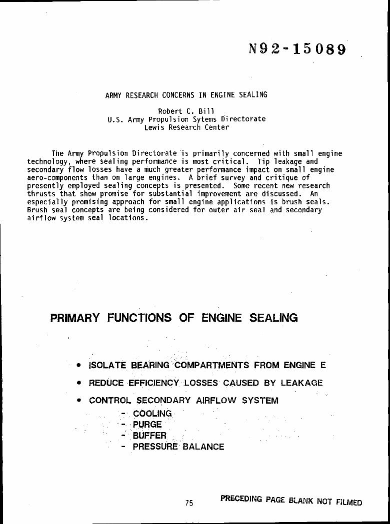
ARMY RESEARCH CONCERNS IN ENGINE SEALING
Robert C. BillU.S. Army Propulsion Sytems Directorate
Lewis Research Center
The Army Propulsion Directorate is primarily concerned with small enginetechnology, where sealing performance is most critical. Tip leakage andsecondary flow losses have a much greater performance impact on small engineaero-components than on large engines. A brief survey and critique ofpresently employed sealing concepts is presented. Some recent new researchthrusts that show promise for substantial improvement are discussed. Anespecially promising approach for small engine applications is brush seals.Brush seal concepts are being considered for outer air seal and secondaryairflow system seal locations.
PRIMARY FUNCTIONS OF ENGINE SEALING
• ISOLATE BEARING COMPARTMENTS FROM ENGINE E
• REDUCE EFFICIENCY LOSSES CAUSED BY LEAKAGE
• CONTROL SECONDARY AIRFLOW SYSTEM
- COOLING- PURGE- BUFFER- PRESSURE BALANCE
75 PRECEDING PAGE BLANK NOT RIMED
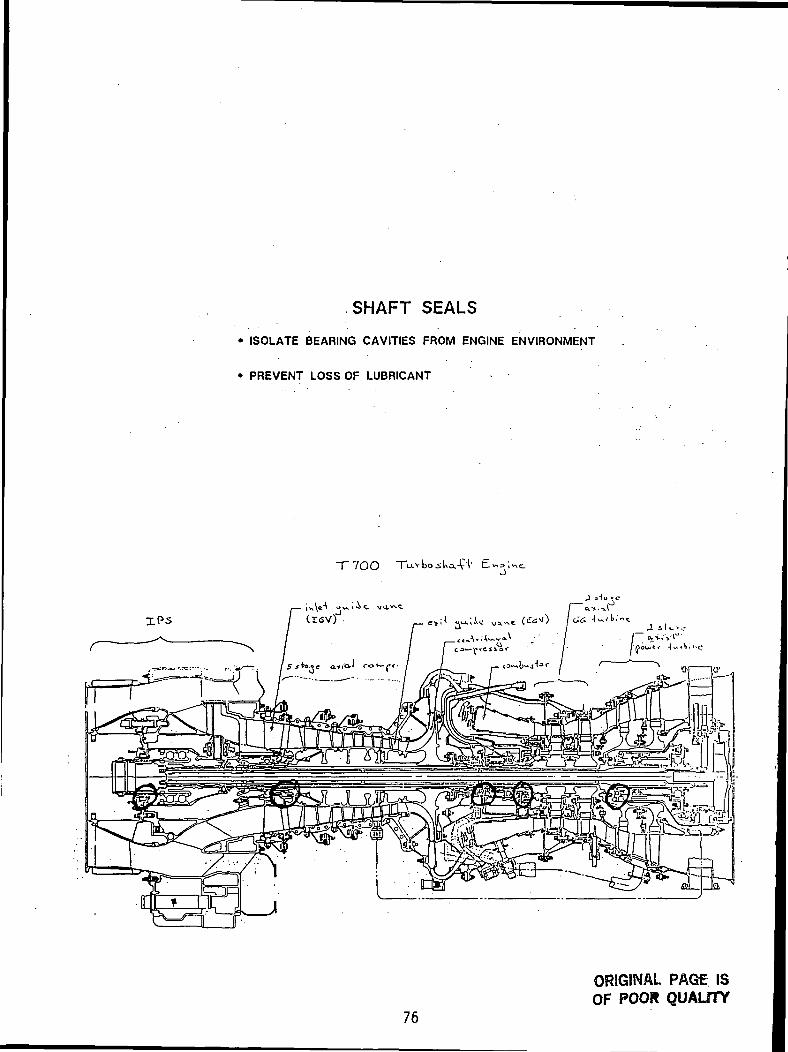
SHAFT SEALS
• ISOLATE BEARING CAVITIES FROM ENGINE ENVIRONMENT
• PREVENT LOSS OF LUBRICANT
"T 7OO
i»\e^ u^;ic v.i>~c(r<sv)
76
ORIGINAL PAGE ISOF POOR QUALITY
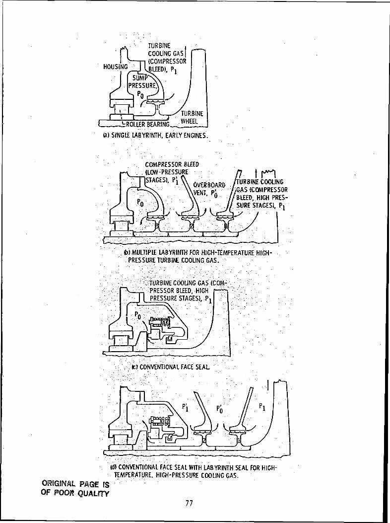
HOUSING
TURBINECOOLING GAS(COMPRESSOR
FTURBINE
-DROLLER BEARING WHEEL
la) SINGLE LABYRINTH. EARLY ENGINES.
COMPRESSOR BLEED. . (LOW-PRESSURE
STAGES). "in
URSINE COOLINGiGAS (COMPRESSORBLEED, HIGH PRES-SURE STAGES), P!
(b)MULTIPlE LABYRINTH FOR HIGH-TEMPERATURE HIGH-PRESSURE TURBIf£ COOLING GAS.
".? ^TURBINE COOUNG GAS (COM- •^,-PRESSOR BLED. HIGH
PRESSURE STAGES). P
; sj|c) CONVENTIONAL FACE SEAL
ORJGINAL PAGE fSOF POOft QUALHTY
(d) CONVENTIONAL FACE SEAL WITH LABYRINTH SEAL FOR HIGH-TEMPERATURE. HIGH-PRESSURE COOLING GAS.
77

SUMMARY - SHAFT SEALS
• MUST FUNCTION AS SEALS - NOT FLOW RESTRICTORS
• RUB CAPABILITY AND TEMPERATURE CAPABILITY OF
MATERIALS ARE TECHNICAL BARRIERS
• NEW CONCEPTS BEING EXAMINED
- "BRUSH" SEALS
- FLUIDIC SEALS
INNER AIR SEALS CONTROL
SECONDARY AIRFLOW SYSTEM
• COOLING AIR TO HOT. SECTION COMPONENTS
• DISK CAVITY PURGE AIR
• PRESSURE BALANCE SYSTEM
• SHAFT SEAL BUFFER AIR
78

I"o"){
UJ
110
oo
79
ORJGiNAL PAGf ISOF POOR QUALITY

MAINTAINING MINIMUM CLEARANCE AND KNIFE-EDGE
GEOMETRY ARE CRITICAL TO LABYRINTH
SEAL PERFORMANCE
1.0,—
— 0.020 CLEARANCE
~ f ^a 010 CLEARANCE
i
1.5 10 2.5 10 3.5SEAL PRESSURE RATIO ff
4.0 4.5 5.0
.75
<=>: .70
.65
_ IfTTf ,f*[TJ''=&-*£•-flti t' /mr
rrtiH
.2 .4 .6 .81.0 10 4.0
TIP THICKNESS TO CLEARANCE RATIO- 1/C
SUMMARY - IAS
• CLEARANCE PREDICTION AND CONTROL ARE
CRITICAL TO RELIABLE FUNCTION OF IAS SYSTEM
• EXISTING FLOW MODELS ARE CRUDE, SEMI-EMPERICAL
• MATERIAL REQUIREMENTS SIMILAR TO THOSE FOR OAS
• STRUCTURAL STABILITY CONCERNS AND GUIDELINES EXIST
- AEROELASTIC INSTABILITIES
- THERMOELASTIC INSTABILITIES
80

OUTER AIR SEALS REDUCE BLADETIP LOSSES
• OVER THE TIP LEAKAGE
• INDUCED SECONDARY FLOW LOSSES
10f-
t
I
O HIGH BYPASS RATIO FANO RESEARCH COMPRESSOR AO RESEARCH COMPRESSOR CO MULTISTAGE COMPRESSOR
a 01 a 02CLEARANCE SPAN-A/S
0.03
- Typiul compressor efficiency penalty as 9 (unction ol bladedearance-to-span ratio
0
-4
-8
-12
-16
-20
-24
\ '"v IMPULSE- V NTURBINE
— \ N\ V
\ \N\
_ \
\\
REAaiON \TURBINE^' \
1 1 1 |N
\\
X
V 1 1" 0 2 4 6 8 10 12
ROTOR TIP CLEARANCE. PERCENT OF" . ANNULAR PAS SAGE HEIGHT
• Effect ol rotor tip clearance onperformance for various turbines
81
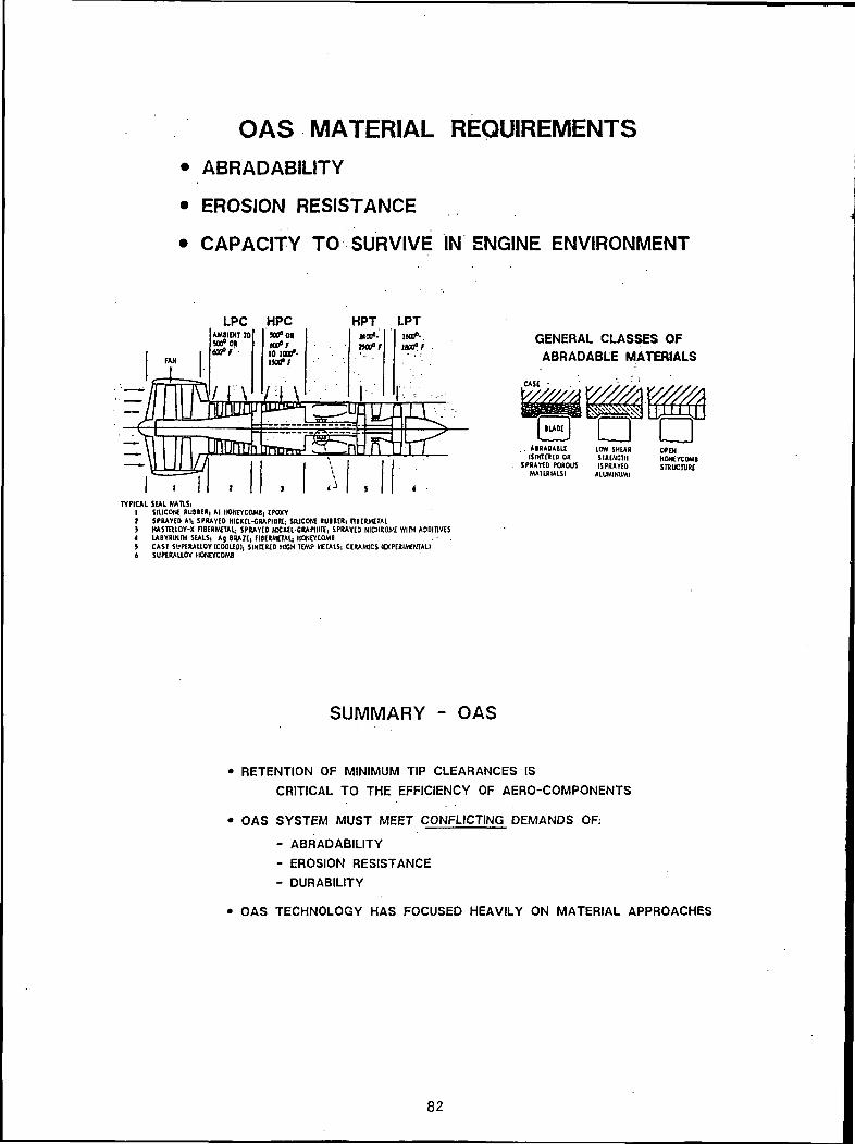
OAS MATERIAL REQUIREMENTS
• ABRADABILITY
• EROSION RESISTANCE
• CAPACITY TO SURVIVE IN ENGINE ENVIRONMENT
LPC HPCx&tttoffTO lOjf-uafi
\ .
HPTJIOO0-naft
LPTuaf-.1803° F
GENERAL CLASSES OFABRADABLE MATERIALS
CASE
THLJrtlr' - ' -H
UJJ
frti . ABRADABLE(SMTEBEO OR
SPRAYED POROUSMMIRIAISI
OPENHONEYCOMBSTRUCTURE
TYPICAL SEAL MATLSi1 SIUCONE RUBBER, Al HONEYCOMBi [POXY2 SPRAYED Al, SPRAYED NICKEL-GRAPHITE* SIUCOHE RUBBCRi FIBERMETAL3 KASTEUOY-X flBERMETAL, SPRAYED NICKEL-GRAPHITE, SPRAYED NICHROME WITH ADDITIVESI LABYRINTH SEALSi Ag 8RA2E, FIBERMCTAL, HONEYCOMB5 CAST SUPERAUOY (COOLED!, SINTERED MICH TEMP TOTALS, CERAMICS (EXPERIMENTAL!6 SUPERALLOY HONEYCOMB
SUMMARY - OAS
• RETENTION OF MINIMUM TIP CLEARANCES IS
CRITICAL TO THE EFFICIENCY OF AERO-COMPONENTS
• OAS SYSTEM MUST MEET CONFLICTING DEMANDS OF:
- ABRADABILITY
- EROSION RESISTANCE
- DURABILITY
• OAS TECHNOLOGY HAS FOCUSED HEAVILY ON MATERIAL APPROACHES
82

92-15090
SEALS RESEARCH AT TEXAS A&M UNIVERSITY
Gerald L. MorrisonTurbomachinery Laboratory
Texas A&M University
The Turbomachinery Laboratory at Texas A&M University has been providingexperimental data and computational codes for the design seals for many years.Dr. Dara Childs began the program with the development of a Halon based sealtest rig. This facility provided information about the effective stiffnessand damping in whirling seals. The Halon effectively simulated cryogenicfluids. Dr. Childs then developed another test facility (using air as theworking fluid) where the stiffness and damping matrices can be determined.This data has been used to develop bulk flow models of the seal's effect uponrotating machinery. In conjunction with Dr. Child's research. Dr. Luis SanAndres has developed a bulk flow model for calculation of performance androtordynamic coefficients of annular pressure seals of arbitrary non-uniformclearance for barotropic fluids such as LH2, LOX, LN2, and CH4. This programis very efficient (fast) and converges for very large eccentricities. Dr.Childs is now working on a bulk flow analysis of the effects of the impeller-shroud interaction upon the stability of pumps.
Dr. Gerald Morrison designed and used this data along with data from otherresearchers to develop an empirical leakage prediction code for NASA Marshall.He is presently studying, in detail, the flow field inside labyrinth andannular seals. Dr. Morrison is using an advanced 3-D laser Doppler anemometersystem to measure the mean velocity and entire Reynolds stress tensordistribution throughout the seals. Concentric and statically eccentric sealshave been studied. He is presently studying whirling seals. The dataobtained are providing valuable information about the flow phenomena occurringinside the seals, as well as a data base for comparison with numericalpredictions and for turbulence model development.
Dr. David Rhode has developed a finite difference computer code for solvingthe Reynolds averaged Navier Stokes equations inside labyrinth seals. He iscurrently evaluating a multi-scale k-e turbulence model. Using his computercode, Dr. Rhode designed and patented a new seal geometry. Dr. Rhode is alsodeveloping a large scale, 2-D seal flow visualization facility.
83
HOLLOWROLLERBEARING
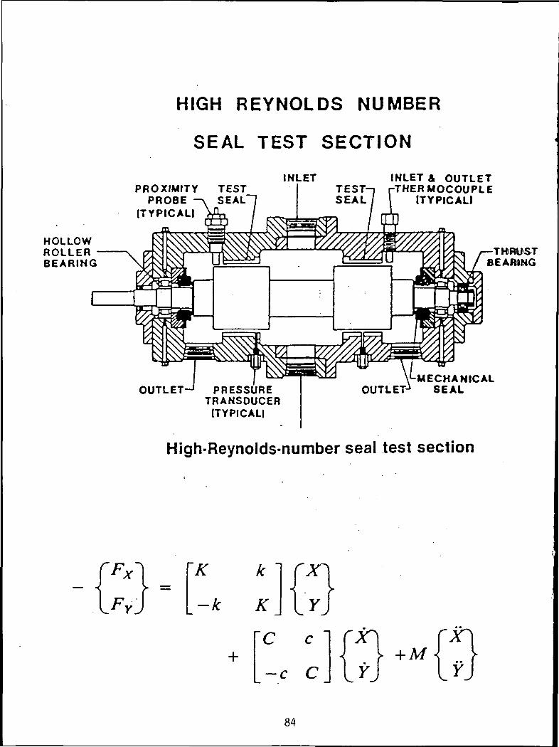
HIGH REYNOLDS NUMBER
SEAL TEST SECTION
PROXIMITYPROBE
(TYPICAL!
INLETTEST
INLET A OUTLETTHERMOCOUPLE
ITYPICALI
THRUSTBEARING
OUTLET-1 PRESSURETRANSDUCER
[TYPICAL!
V-MECHANICALOUTLET* SEAL
High-Reynolds-number seal test section
'K
84
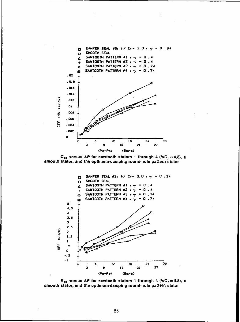
DAMPER SEAL 03,SMOOTH SEALSAWTOOTH PATTERN 01 .SAWTOOTH PATTERN 02
*/ O- 3.0 .34
- 0• -y - 0
SAWTOOTH PATTERN 03 i -y - 0SAWTOOTH PATTERN 04 , y - 0
447474
zoa
27
C,j versus AP for sawtooth stators 1 through A (h/Cr = 4.8), asmooth stator, and the optimum-damping round-hole pattern stator
ao
DAMPER SEAL «3iSMOOTH SEALSAWTOOTH PATTERN *1SAWTOOTH PATTERN #2SAWTOOTH PATTERN 03SAWTOOTH PATTERN *4
h/ Cr- 3.0 - 0 .34
-0.4-0.4- 0 .74- 0 .74
X
2
(Po-Pb) (Bare)
Kef versus AP for sawtooth stators 1 through 4 (/)/Cr = 4.8), asmooth stator, and the optimum-damping round-hole pattern stator
85
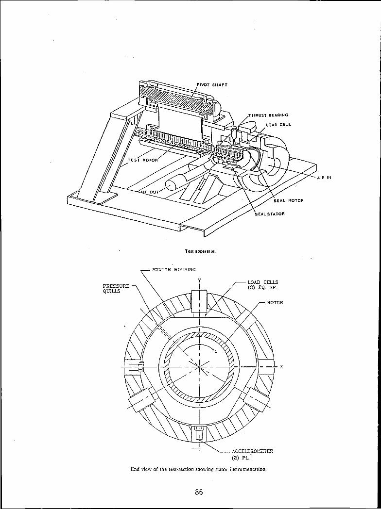
PIVOT SHAFT
,THRUST BEARING
LOAD CELL
SEAL ROTOR
SEALSTATOR
AIR IN
Test apparatus.
PRESSUREQUILLS
STATOR HOUSING
~l
LOAD CELLS(3) EQ. SP.
ROTOR
ACCELER01.ETER(2) PL.
End view of the test-section showing stator instrumentation.
86
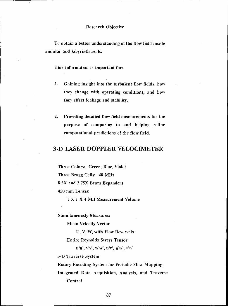
Research Objective
To obtain a better understanding of the flow field inside
annular and labyrinth seals.
This information is important for:
1. Gaining insight into the turbulent flow fields, how
they change with operating conditions, and how
they effect leakage and stability.
2. Providing detailed flow field measurements for the
purpose of comparing to and helping refine
computational predictions of the flow field.
3-D LASER DOPPLER VELOCIMETER
Three Colors: Green, Blue, Violet
Three Bragg Cells: 40 MHz
8.5X and 3.75X Beam Expanders
450 mm Lenses
1 X 1 X 4 Mil Measurement Volume
Simultaneously Measures:
Mean Velocity Vector
U, V, W, with Flow Reversals
Entire Reynolds Stress Tensor
u'u', vV, w'w', uV, u'w', v'w'
3-D Traverse System
Rotary Encoding System for Periodic Flow Mapping
Integrated Data Acquisition, Analysis, and Traverse
Control
87

The 3-D LDA system is uniquely qualified for this study
due to:
1. The small size of the probe volume (0.001" X 0.001"
X 0.004").
2. The non-invasive nature of the measurement device.
3. The ability to measure the mean velocity and the
entire Reynolds stress tensor.
4. Ensemble averaging capability for use on whirling
rotors.
5. The ability to measure flow reversals.
'ft
Texas A&M Seal Rig Composite Drawing
OpticalWindow
Flow
Rotor/ / /
- Flow
J

FIRST CAVITY
/ *~ —/ -- _/ ' _
I\ X .
^ C :\ >- ~<' I
THIRD CAVITY
-r- ~~
',' /
/
{\\\\X
— ~~
^
it
\V>.
••
~" — \' " \— X
* 1
* t
J '
*• s— __ •
1
7/
1\ •N -
— ~x __^ ""/i ",\\ „
- ^-, --*\ \\\\1
\ \
\t
s *'
FIRST CAVITY
_ . —_.
— •.f t ; i :I ' ' *J » : ;\ \ _ *» N - f\ V -. .\ ^ _ ^
\\1]//r
SEVENTH CAVITY0 DEC
THIRD CAVITY
SEVENTH CAVITY180 DFG
Mean Velocity Vector Fields, 6 =0" and 180".
89

0.1.0 X/C2.0 3.0
FIRST CAVITY
• x/cTHIRD CAVFTY
2,0 3.0
1.0 X/C2.0 3.0
FIRST CAVITY
0.' x/c
.THIRD CAVITY
2.0 3.0
2.0 3.0
o.t ai —ai —ai —0.1 —0.1 —0.1
0. 2.0 3.0"w x/c"" """ w'~ x/c
O OFG 180 OEG
Mean Azimuthal Velocity Contours, Us/Wsh, ^ =0" and 180".
90

2.0
Y/C
1.0
ai 0.1—ai
ai ai — — ai
1 J
0,.0 x/(;2.0 3.0
FIRST CAVITY
2.0
Y/C
1.0
O.C
,0.1 at -o.»
3.0
2.0
Y/C
1.0
3.0
• x/cTHIRD CAVITY
2.0 3.0
,.0 X/C2.0 3.0
3.0
1.0 x/(.2.0 3.0
FIRST CAVITY
3.0 -
acb. ' x/cTHIRD CAVITY
2.0 3.0
a, —0.1 —ai —ai —ai —ai —-ai -
O.C... x/(;2.0 3.0
SEVENTH CAVITY
180 DEC0 DEC
Turbulent Kinetic Energy Contours, K/TJ2, 9 =0 and ISO".
91 ORIGINAL PAQf isOF POOR QUALITY
2.0
Y/C
1.0
•TJ.O
2.0
Y/C
1.0
}.0
2.0
Y/C
1.0
0.
' x/cRRST CAVITY
2.0 3.0
THIRD CAVITY
,0 1.0 X/C2.0
0 DEC
3.0
' x/cFIRST CAVTTY
2.0 3.0
3.0 :
X/C.THIRD CAVITY
2.0 3.0
1'° x/c2-0
SEVENTH CAVITY
180 DEC
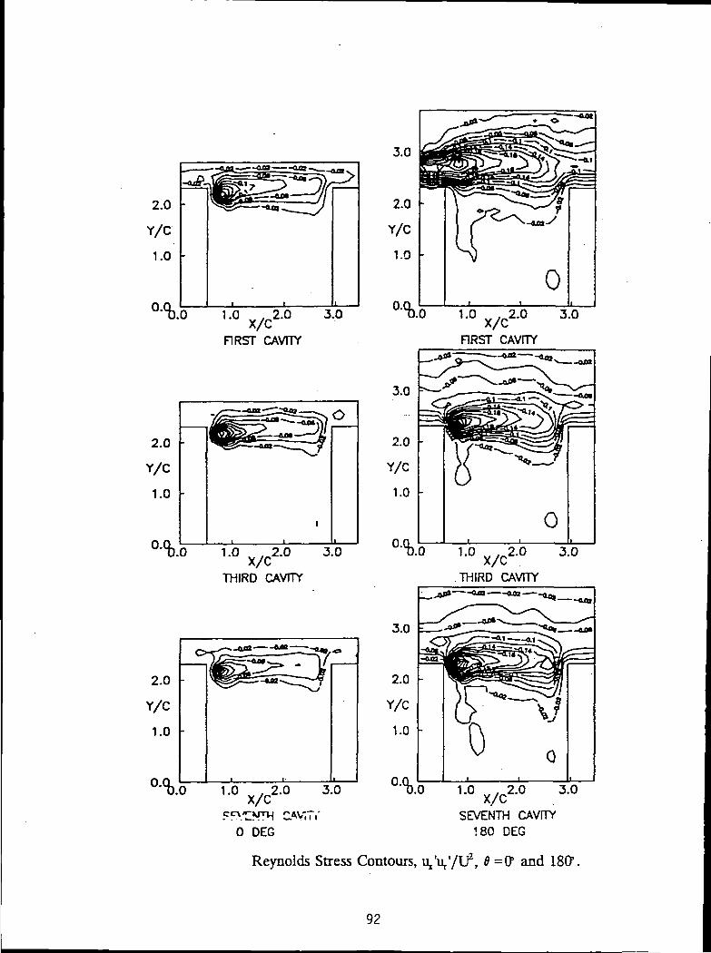
Reynolds Stress Contours, U/U//U2, 6 =0" and 180".
92

Measurements To Date:
Type of Seal
Annular
Annular
Annular
Annular
Annular
Annular
Annular
Annular
Labyrinth
Labyrinth
Labyrinth
Labyrinth
Labyrinth
Whirl
None
None
None
..None
None
None
None
None
None
None
None
None
None
Eccentricity
0
0
0.5
0.5
0.5
0.5
0.5
0.5
0.5
0
0
0
0
RPM
3,600
0
3,600
3,600
3,600
500
1,500
3,000
3,600
L 3,600
3,600
3,600
5,300
Re
28,000
23,000
23,000
23,000
28,000
0
0
0
28,000
28,000
28,000
28,000
15,000
Ta
7,000
0
7,000
7,000
7,000
970
2 )00
5,800
7,000
7,000
7,000
7,000
10,300
Swirl
None
None
None
+ 45*
-45°
NA
NA
NA
None
None
+ 45°
-45°
None
Plug
Yes
Yes
Yes ,
Yes
Yes
NA
NA
NA
None
None
Yes
Yes
None
Measurements To Be Made This Year
Type of Seal
Annular
Annular
Labyrinth
Labyrinth
WhirlRatio
1.0
1.0
1.0
1.0
Eccen-tricity
0^5
0.5
0.5
0.5
RPM
3,600
5,300
3,600
5,300
Re
28,000
15,000
28,000
15,000
Ta
7,000
10,300
7,000
10,300
Swirl
None
None
None
None
Plug
Yes
Yes
Yes
Yes
93

12.7 cm6.4cm "5.1emfW)
6.1mm
15.2cm
2.5cm
Pressure tap
O-Ring
Spacer (H)
TMt Mock
Flat plate tester assembly.
94

P=15.
0.07 -,
0.06-
0.05-K.O
< 0.04-
| 0.03-Occ
0.02-
0.01 -
0.00-1
2 BAR, CELL DEPTH=2.29mm. CLEARANCE=0.38mm
CELL WIDTH
' _ « — •— SMOOTH1 -« ' — t— 1.57mm» - - • » " - «• 0.79mm
—5-- 0.51mmX
— *»- 0.41mmsmooth pipe
/ from Moody
•+*- _ ' _ — -f"~ •¥- — —rr- ~
X
&__K^ / ^-o-."~— -^ e-- ' - -—o
J
diagrs
0000 20000 30000 40000 50000 60000 70000 80000
REYNOLDS NUMBER
im
A typical friction-factor pattern.
o.oaz — Feedback mode resonance
Normal mode resonance
-I 0.000
in
~i o.ooo
0.000
o.oco
0.000
Re Ma
40000
32000
30000
25000
20000
0.23
0.!9
0.16
' 1TOOO' ' I ' ' 'o zooop ' 40000 eoooo eoooo 10000028000 NCY ( H z )
Frequency spectra for test number
( b=1.5T, d=3.05 and H=0.25mm )
95
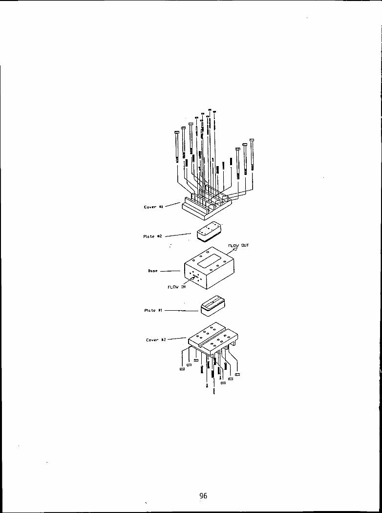
Cover il
Plate *a
Base
Plate «1
Cover tZ
96
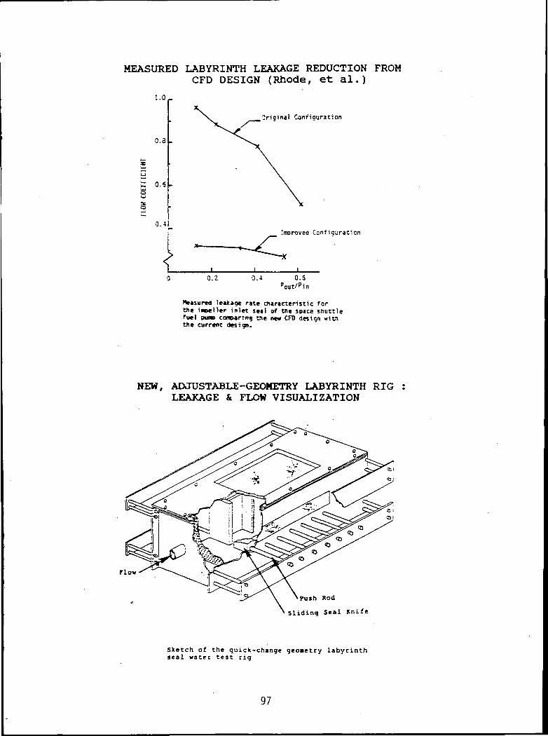
MEASURED LABYRINTH LEAKAGE REDUCTION FROMCFD DESIGN (Rhode, et al.)
i.o
0.3
t 0.5
0.4
Original Configuration
Imoroved Confiauraticn
0.2 O.Spaut/pin
Measured leakage rate characteristic fortHe livelier inlet seal of We space shuttlefuel pinv com>»ring the n«« CFD design witnthe current design.
NEW, ADJUSTABLE-GEOMETRY LABYRINTH RIGLEAKAGE & FLOW VISUALIZATION
Flow
Push Rod
Sliding Seal Knife
Sketch of the quick-change geometry labyrinthseal water test rig
97
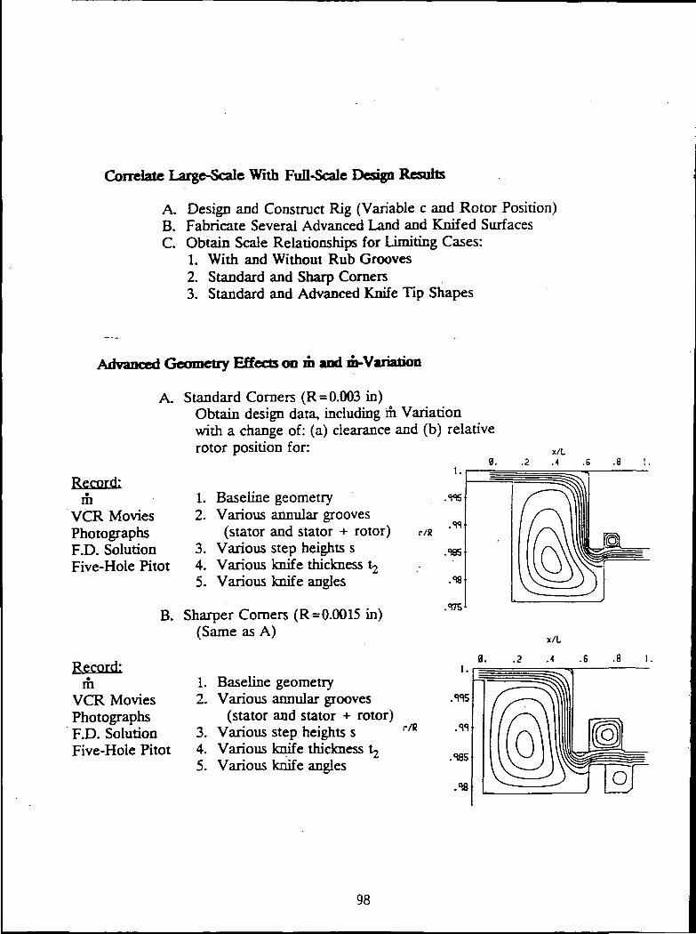
Correlate Large-Scale With Full-Scale Design Resorts
A. Design and Construct Rig (Variable c and Rotor Position)B. Fabricate Several Advanced Land and Knifed SurfacesC. Obtain Scale Relationships for Limiting Cases:
1. With and Without Rub Grooves2. Standard and Sharp Comers3. Standard and Advanced Knife Tip Shapes
Advanced Geometry Effects on m and m-Variation
A. Standard Corners (R = 0.003 in)Obtain design data, including m Variationwith a change of: (a) clearance and (b) relativerotor position for:
Record:m
VCR MoviesPhotographsF.D. SolutionFive-Hole Pilot
B.
Record:rh
VCR MoviesPhotographsF.D. SolutionFive-Hole Pitot
1. Baseline geometry2. Various annular grooves
(stator and stator + rotor)3. Various step heights s4. Various knife thickness ^5. Various knife angles
Sharper Corners (R= 0.0015 in)(Same as A)
1. Baseline geometry2. Various annular grooves
(stator and stator + rotor)3. Various step heights s4. Various knife thickness ^5. Various knife angles
r/R
i.
r/R
x/L
6 .8 1,
98

Research Object ives on Annular Sealsfor 1991 -92 at T e x a s A&M University
P.I. Dr. L. San Andres
Analysis of thermal e f fec ts on the performanceand dynamic force response of high pressureannular seals handlinq cryogenic liguids.
Adiabatic and Constant Surface Temps.
Important for LOX due to higher viscosityand lower specific heat than LH2.
Development of a unified theory for liquid, gas,and two-phase flow annular seals.
Calculation of dynamic force and moment coef fs.for displacements and angular motions.
Analysis of high pressure OIL SEAL RINGS forcompressors: single and multi-land seals.
Calculation of lock-up forces andface fricton factors.
Study of Damper Seals and Hydrostatic Bearingsas support elements in cryogenic turbopumps.
Improved Seal Entrance Factors by CFM simulations
99

hsea l . f A , • i T u i i n <Analysis .of Turbulent FlowAnnular P ressu re S e a l s
Dr. L. SanAndres, Texas A&M University
,. 2-D Bulk Flow Model for barotropic liquids
Sur face roughness: Moody js friction fac to r :
• Arbitrary Axial Clearance Distribution:uniform, taper, step, wavy via spline, andstator wear profile
* Arbitrary Static Eccentricity Ratio,
• Realistic liquid propert ies for LH2, LN2, LOX, CH4
'rogram calculates:
Leakage, Fluid Film Forces , Torque, and
Rotordynamic Coef f ic ients: Kij, Cij, Mij
Solution scheme based on efficient CFM methods
and improved approx imate guesses for f as t
convergence.
Program can be used for f looded or grooved
journal bearings.
Laminar and/or Turbulent Sea ls and Bear ings
100

N92-15091
SEALS RESEARCH AT THE UNIVERSITY OF AKRON
M.J. BraunUniversity of Akron
Akron, Ohio
FLOW AND PRESSURE STUDIES ON BRUSH SEALS
The flow visualization effort aims at determining the flow regimes and thesealing mechanisms that are at work in the brush seal, regardless of whetherthe seal is linear or circular. A vision system coupled with an imageprocessing system is used to analyze the nature of the flow.
Pressure measurements were made to study the effect of the number of brushesas well as the brush structure on the seal effectiveness.
NUMERICAL SIMULATION OF FLOW IN A HYDROSTATIC POCKET
This portion of the presentation will detail a numerical approach to flowsimulation in one hydrostatic pocket. The effects of the jet, shaft velocityand clearance on the flow patterns and pressure generation will be described.
101
N92-15092
PROGRAMS AT WRIGHT PATTERSON AIR FORCE BASEWL/POSL
Ron DaytonWright Patterson Air Force Base
The Lubrication Branch hasJtwo active programs'that1are developing gas turbineengine mainshaft air/oil seals. Both of these •programs,'one of which is withGeneral Electric .Aircraft. Engines and_the other with Pratt & Whitney Aircraft,are addressing' counter-rotating inteirshaft applications which involve veryhigh rubbing velocities. My presentation will briefly address the•objectivesand requirements of both of these efforts.
- ' ' ' - - - * '
• . .j-r.-.-F;'-' '. rn: :»r- i 'vv-r rv : ' - i f v . • • : - • ' • . • • • ;
HIGH-SPEED AIR/OIL SEAL DEVELOPMENT
CONTRACTOR: UNITED TECHNOLOGIES (PRATT & WHITNEY)
CONTRACT NUMBER: F33615-88-C-2822
START/DURATION: SEP 88 / 45 MONTHS ' - • :..^"!".;
OBJECTIVE: ' CONpUCTA COMBINED^ANAIiYTICAL AND EXPERIMENTAL-i.'. PROGRAM TO bEVECOP-ANb''ENp'URANCETESt- ;
• ' : ' ' ' - COUNTER-ROTAf ING INTERSHAFPSEAlIS FOR RELIABLEOPERATION UP TO 1200 FT/SEC PITCH LINE
../.VELOCITY
GOALS: '* 4000 HOUR SEAL LIFE* 1200 FT/SEC PITCH LINE VELOCITY- '* 50 LB/HR MAX AIR LEAKAGE @ 50 PSID & 750 F* 500 LB/HR MAX AIR LEAKAGE AFTER PRIMARY SEAL
MALFUNCTION* -MISALIGNMENT TOLERANCE ,
103PRECEDING PAGE BLANK.NOT FILMED

HIGH SPEED AIR/OIL SEAL DEVELOPMENT
APPROACH:
DEFINE THE SEAL APPLICATION AND ESTABLISH REQUIREMENTS
SELECT TWO SEAL CANDIDATES THROUGH AN ANALYTICALASSESSMENT OF PERFORMANCE POTENTIAL FROM A MINIMUMOF FIVE SEAL DESIGNS
FABRICATE AND EVALUATE THE PERFORMANCE CAPABILITIESOF BOTH SEAL DESIGNS
SELECT THE BETTER OF THE TWO SEAL DESIGNS FORENDURANCE TESTING
ENDURANCE TEST THIS SEAL FOR AN ADDITIONAL 80 HOURS
EVALUATE TEST RESULTS TO IDENTIFY IMPROVEMENTS NEEDEDAND POSSIBILITY OF TRANSITION INTO THE JTDE PROGRAM
HIGH SPEED AIR/OIL SEAL DEVELOPMENT
STATUS:
SEAL DESIGN REQUIREMENTS WERE BASED ON AN ADVANCEDFIGHTER-TYPE AIRCRAFT WITH A 60% INCREASE IN THETHRUST-TO-WEIGHT CAPABILITY OF CURRENT STATE-OF-THE-ART SYSTEMS
TWO SEAL DESIGNS, A CONTROLLED GAP SEAL CONCEPT AND ASEGMENTED HYDRODYNAMIC CIRCUMFERENTIAL SEAL, WERESELECTED FROM 25 CANDIDATES
FABRICATION OF THE CONTROLLED GAP SEAL DESIGN ISIN PROGRESS
FABRICATION OF THE SEGMENTED SEAL IS COMPLETE
SHAKEDOWN TESTING OF THE EG&G SEALOL TEST RIG HASBEEN COMPLETED
104

COUNTER-ROTATING INTERSHAFT SEALDEVELOPMENT
CONTRACTOR: G.E. AIRCRAFT ENGINES
CONTRACTOR NUMBER:* F33615-90-C-2000
START/DURATION: APR 90/29 MONTHS
OBJECTIVE: DEVELOP AN ADVANCED DESIGN INTERSHAFTSEAL FOR PHASE IIIHPTET ENGINE CONFIGURATIONS THATUTILIZE COUNTER-ROTATING TWIN SPOOLS
GOALS:
. 900 FT/SEC PITCH LINE VELOCITY
. APUPTO50PSID
. 900°F SEAL AIR INLET TEMPERATURE
COUNTER-ROTATING INTERSHAFT SEALDEVELOPMENT
APPROACH:
ADVANCED DESIGN BASED ON AN AIR BEARING-SUPPORTEDCONTINUOUS RING CONFIGURATION
THREE MATERIAL APPROACHES FOR CRITICAL SEALINGINTERFACE:
(1) CONCURRENTLY DEVELOPED ADVANCED HIGHSTRENGTH CARBON (> 100KSI PER LB/INJ)
(2) STATE-OF-THE-ART METALLIC MATERIALS
(3) INLAID ARRANGEMENTS OF CARBON, METAL,AND/OR CERAMICS
105

COUNTER-ROTATING INTERSHAFT SEALDEVELOPMENT
APPROACH rCON'T):
CONDUCT PHYSICAL AND TRIBOLOGICALCHARACTERIZATION TESTS TO SELECT BEST MATERIALAPPROACH
FOR SELECTED APPROACH, DESIGN AND FABRICATEFULL-SIZE PROTOTYPE SEAL
CONDUCT SEAL TESTS IN TWO PHASES:
(1) PERFORMANCE MAPPING(2) ENDURANCE FOR UP TO 200 HRS
BASED ON TESTS, DESIGN SEAL FOR THE PH IIDEMONSTRATOR ENGINE
COUNTER-ROTATING INTERSHAFT SEALDEVELOPMENT
STATUS:
• MATERIAL CHARACTERIZATION TESTS UNDERWAY
• PROMISING RESULTS OBTAINED WITH ADVANCED CARBONMATERIALS
(1) HIGH STRENGTH
(2) GOOD OXIDATIVE RESISTANCE
106
92-15093SEAL DEVELOPMENT ACTIVITIES AT
ALLISON TURBINE DIVISION
John Munson
Brush Seals
Brush seals are being evaluated for potential near and far term gas turbineengine applications. Development is in the form of rig component testing, andengine testing. Allison has tested an engine with 20 individual brush sealpositions. These seals were located throughout the engine. The emphasis ofthe current work is on obtaining long term performance data for brush seals.Very little of this data is available.
Film Riding Face Seals
Allison is presently developing film riding face seal technology to supportfuture gas turbine engine applications. Face seal with an approximate 7"diameter has been successfully tested to 1000°F, 100 psid, and 650 ft/sec.Seal leakage remained below 1 scfm throughout the duration of the test. Amodel for the compressible gas film has been developed which separates theprimary seal rings during operation. This model is based on the traditionalReynold's approach which is customarily applied to lubrication type problems.Because of the difficulty of experimentally verifying the program predictions,a commercial Navier-Stokes code was used in parallel. By comparingpredictions for similar cases, it is expected that the limitations of theReynold's model can be assessed as it applies to this particular seal.
107

2-15094AREAS OF SEAL R&D AT GE
A. N. PopeGeneral Electric Company
About four years ago, work was completed on a 36 inch diameter gas to gascarbon ring seal used to buffer low pressure turbine air at the rim of theforward outer flowpath on the GE36 unducted fan (UDF) engine. This highlysuccessful program demonstrated the ability to provide long life at a gasleakage rate equivalent to a .0018 inch clearance, or, conservatively estimat-ing, a 20 to 1 reduction over a labyrinth, and an SFC reduction of at least2.5%. Operating conditions were 1600 rpm (240 fps), 60 psid and 650 deg F.The seal design was based on the use of self-acting gas hydrostatic bearings.
At about the same time, we were working an AF/Navy contract for development ofa long life counter-rotating intershaft air-oil seal of approximately 7.6 inchdiameter for operation at 800 fps, 800 deg F and 50 psid. Although we weresuccessful in meeting most program goals with a split ring seal of the axialbushing type, the seal with the greatest payoff in life and air leakage rates,bearing many features common with the GE36 seal, could not be successfullytested because of the structural weakness of the primary seal ring carbonmaterial. This was a split ring seal using a hybrid combination of orificecompensated hydrostatic and shrouded hydrodynamic gas bearings. We arepresently working an AF contract to develop this design in conjunction withhigh strength carbon materials being developed by Pure Carbon Co.
In the area of engine secondary gas flow path sealing for performance improve-ment, we are currently working with carbon and all metal face seals. Nineinch diameter hydrodynamic carbon face seals at 450 fps, 140 psid and 950degrees F, have demonstrated long life at a flow reduction of approximately96% (7.5 scfm) compared to a "best" labyrinth. A fifteen inch diameter allmetal "aspirating" face seal, using self-acting hydrostatic bearings, has beensuccessfully tested to 700 fps, 100 psid and 1000 deg F, demonstrating longlife at a flow reduction of 86% compared to a "best" labyrinth. This sealwill be developed through 1400 deg F, 900 fps and 350 psid. The seal "aspi-rates" closed at about idle speed pressure during engine start and reopens atengine shutdown.
A hydraulic thrust balance "seal", currently using orifice compensatedhydrostatics, is under development. We have demonstrated long life operationfor most large engine low pressure rotor applications (170 fps) with 30000pounds control at 7 inches diameter and less than 3 gpm flow rate using Type 2(23699) engine oil. We are now working high pressure rotor systems, to 450fps. This program has two significant payoffs: 1) as much as 50 to 1increase in thrust bearing fatigue life, 2) as much as 3% reduction in SFC andsignificant multipliers in turbine bucket life.
109PRECEDING PAGE BLANK NOT FILMED

ft)5O
110
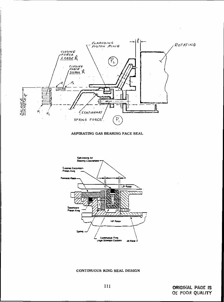
f?OT/VT IM G
ASPIRATrNG GAS BEARING FACE SEAL
Spnnq.
Coranjou* fling(Hkjn Strangui Caitxxii AR Ran •
CONTINUOUS RING SEAL DESIGN
111 ORIGINAL PAG? fSO£ POOR QUALITY

1 Primary Seal Elements2 Outer Race. Rotating3 Fwd Race. Stationary4 Aft Race. Stationary5 Axiai Springs6 Piston Ring. Stationary7 Radial Bushings8 Piston Ring. Rotating9 Radial Splines. Clamp-Hace
10 Carrier. Stationary Pistion Ring11 Clamp Ring12 Clamp Spring13 Adapter. Seal to Frame14 Flange. Engine Frame15 Radial Splines. Fwd-Aft Races16 Retainer Lugs. Carbon Segment
LARGE DIAMETER HYDROSTATIC SEAL
112
N92-15095SEAL RELATED DEVELOPMENT ACTIVITIES AT EG&G
H,F. GrinerFluid Components Technology Group
EG&G
A brief introduction is made describing EG&G Fluid Components Technology Groupand FCT Group R&D capabilities.
Seal related development activities, including modeling, analysis andperformance testing are described for several current seal related projects.These include noncontacting, high speed, high pressure gas sealing systems forturbomachinery, brush seals for gas path sealing in gas turbines andtribological material evaluation for wear surfaces in sealing systems.
GROUP R&D
Staffed and equipped (or:
Material Characterization and Analysis
Tribological Characteristics, Testing and Evaluation
High Temperature, High Pressure and High Speed Testing
of Seals and Sealing Systems
Mechanical Design of Products and Specialized
Testing Equipment
Modeling of Systems and Components, Design Analysis
and Performance Parameters
Manufacturing Process Development
113

ADVANCED AEROSPACETEST RIG
Rig Capabilities (Counter RotatingConfiguration)
- Spiudk- Speed/24,000 RPM each shaft
- Power/43 HP at 17,000 RPM. 32 HP at 26.000RPM
- Temperature of Test Cliamber/GOO°F
- Test Chamber Pressure/100 PSI
- Axial Travel/±.0625 inch each shaft
Single Shaft (Brush Seal Testing)
- Spindle Speed/24,000 RPM
- Power/43 HP at. 17,000 RPM. 32 HP as 2h.OODIli-'M
- Temperature of Test Chamber / 100'i'F
- Test Chamber Pressure/ 100 PSI
- Axial Travel/±.OG25 incites
*ypfc^^o——i r, t-FZ-f- 'tH, hiVy-n-^ ) ' -flCi-. | W J .
114
ORIGINAL PAGE JSOF POOR QUALFTY

SEAL RELATED DEVELOPMENT ACTIVITIES
BRUSH SEAL DEVELOPMENT PROGRAM
U. S. AIR FORCE PRDA-11
IN-HOUSE BRUSH SEAL TESTING
NON-CONTACTING GAS FILM SEALS
DEVELOPMENT AND TESTING
TRIBOLOGICAL MATERIAL EVALUATION
ANALYSIS AND TRIBOLOGICAL TESTING
Brush Seal Development Program \
U. S. Air Force
Integrated High Performance Turbine Engine Technology — IHPTET
PRDA -II
Objective: Develop a comprehensive design methodology (or Brush Seals
using
1. Application requirements from engine manufacturer
2. Experimental characterization of seal design and triboiogical pairs
Goals: 1. Substantially lower leakage than laby seals
2. Seal life consistent with man -rated mission requirements
3. Achieve maximum pressure sealing capability with single ormultiple stages
Provide: 1. Comprehensive seal design manual
2. Man-rated brush seal for test in an IHPTET engine
Project duration is two and one half years, started July 1990
115 ORIGINAL PAQf ?§•OF P008 QUALITY

PACK IVI Dili IBACKING %WASHLR \
r
0D,
0Dh
_ M(MT MIN.TYP
FREE U:NGTI
RETAININGWASHER
•COVER PLATEOR
SIDE PLATE
0Dr
00:
WIRE DIAMETER- dTOTAL NUMBER OE BRISTLES- n,WIRE DENSJTY-jD
BRUSH SEAL ASSY.
FLOW PARAMATER VS DP/P. COMPARISON OF BRUSH SEALAND LABYRINTH SEAL LEAKAGE
_ ot/1 2
O <nU) o
'
Ul o\— 10< o
LEGENDD = EPD TESTS 5500 RPMo = EPD TESTS 9700 RPM^ = EPD TESTS 11600 RPM+ = EPD EH TESTS 6K-15K RPMx - TELEDYNE TESTS 30000 RPMo = EPD 6 FIN LABY (.025 GAP)? = ALLISON 4 FIN (.02 GAP)
O.i
116
ORIGINAL PAGE ISOF POOR QUALITY
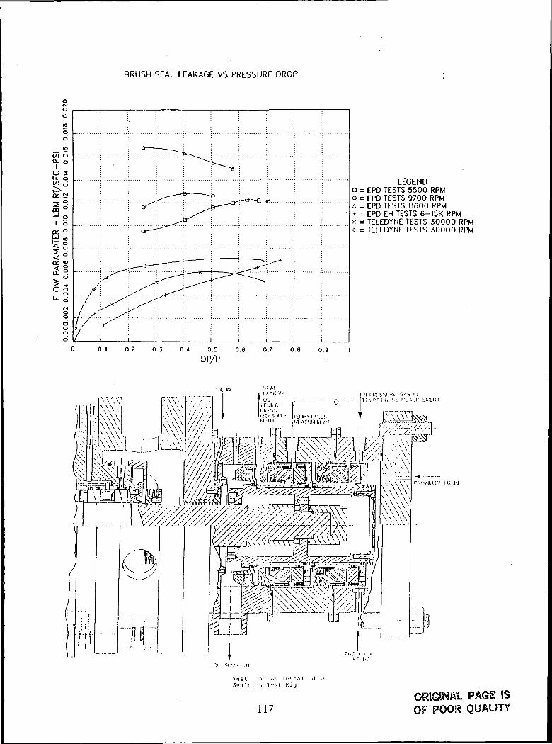
BRUSH SEAL LEAKAGE VS PRESSURE DROP
0.8 0.9
LEGENDa = EPD TESTS 5500 RPMo = EPD TESTS 9700 RPMA = EPD TESTS 11600 RPM+• = EPD EH TESTS 6-15K RPMx = TELEDYNE TESTS 30000 RPMo = TELEDYNE TESTS 30000 RPM
DP/P
Oil IN
rui'xe.m i lijtu
Tost •;«! />^ in tit: a 1 I (M! InScale. ;; T"si Hic j
117PAGE !S
OF POOR QUALITY

num-:i( CAS TNHOUGII FII.TKKS
GAS LEAKAGE TO STACK
PATENT PENDINGTandci Ciis Fdce Sciil - Sliuwn in Tlu:i ooilyn i.'.inlri tui;iil (;^s Coafii
Oil. 1JHA1N I J U F F E R G A b Ul'I-'EII GASAT BOTTOM L E A K A G E »N,,TYK)POSITION (TO STACK AT I'systcnl + £. P
IF FLAMABLE)
PROCESS • SAT PsysU-m
DAMPING DEVICE
FLUIDF I L M
i . ' l l tCUMFEK- FINGEI1 S P l i l N c ;KNT1AL L E A K A G E CENTE1IINGCONTKOI. S K A L DE\'ICE (TYI!)
I I U K F E I t G A Sri.uw INTO
METAL BELLOWS GAS SEAL (PATENT P E N D I N G )(BUFFER GAS A I I R A N G E M E N T )
118ORIGINAL PAGT ISOF POO^ 0".ft! TTY

SEAL L E A K A G E OUTTEMR AMD PRESS.MEAS.
HIC I PRESS. CAS INTil IIKAT 'IXCIIANIiKU '.EMBAHO PRESS.
MCAS.X; TO Bli CLOSED
[••ROM MEAT EXCHANGER
Dynamic Tesi. Arr,-]|ii;finioi)i. <>r a T h i n l i n e Gns Seal
Energy Dissipation vs. Pressure
Single, data per pod
o —
7 —
n: 6 —
1 5-E
oo 4 —00Q J
s 5iCC
2 2 -:
SPEED
A 5000 RPI.1
B 7500 RPM
^ 12500 RPM
0 MOOO RPM» 15000 RPM
+ 16000 RPM
15500 RPM
\^
^^^^ ^1
^"*^"".--'"^-«""""""0 J
^^ -''* •"'' f'""'*
f *^::-:*::""I''-'-*-'-*"""*'"— ^-*^^"«-''' -•-*"'"" •: s' '*'''' .-••*""
) _±:C<??|:.' -•-*''" _ B B D • »
0 J^" _ ....a a » • " •-
_ M H •• , » A« . . - 7 T A A * •* f -f "A — " — If— n ' — t 1 — t — < 1 — r — i — i ' —
100 500 700 900
SYSTEM PRESSURE PSIG
1100 1300 1500
119 OF POOF? QUALITY

Inlet Temperature vs. Pressure
Single, data of POD 2
'NJU -T-
350-u_
O£ 300-UJ££ 9 enZ3 i ~*U
<f -o:a! 200-UJ
1 I
100-
,-
SPEED
A 5000 RPU
B 7500 RPI.I
^ 12500 RPU
9 14000 RPU
8 15000 RPH+ 16000 RPU
*
15500 RPH\\\
— -+ — _K^- — "'
+ + "^ ^--*-~~~*~~^ ^A— j^ K — ' " _g —
+ « - « - * . _ _ « - *
_..*-—*-— *"""*"""*~""*"" *
^..+-'~~
."" '
50 T
H m ....g ,
, " • ; * " A1 1 1 i ! 'I I I 1 1 1
100 300 500 700 900
SYSTEM PRESSURE PSIG
100 1300 1500
Leakage vs. Pressure
Single, data of POD
1 ."! —
1.2-
-
•
b^ 0.8-UJ
^ 0.6-<t
SPEED
'. A 2500 RPU .„-« <• 5000 RPU ,--•-""*"
— ,, •'
4 7500 RPM •----•"" •'•"8 12500 RPU ,•-"" ,-*-•'"*'^--' ..*-•
, *'' -•'*" . • - - • • • • " "x' ..-*'' ...•• "
L-i-J ^ - "^ ^ , •' '"
-1 0.4^ ^' ..^•"'*' „........-• -•"T ''' ,*^ _...•••••"* ^-^L
0.2^- / / . .^
T / / /n o T / 1 / 1 ix • , i , i ,U.L | A | A | A i 1 | 1 - • j- — 1 |
100 300 500 700 900 1100 1300 15C
SYSTEM PRESSURE PSIG
120ORIGINAL PAGE 8SOF POOR

Leakage vs. Pressure
o
Single, data of POO
1.4
1.2
1.0
0.3 —
0.6
0.4 -
0.2 -f^
0.0 -:
*' /' / •'
|
100 300
.•••-" ,-•-
-I-
500 . 700 900 1100
SYSTEM PRESSURE PSIG
15000 RPM
and
15500 RPM
?500 i.-uu
o(/->
<a:
Leakage Correlation
Single, data of POO I
1.6LEGEND
A. 5000RPU. TESTB 5000RPM, CALC.$ 7500RPM. TEST• 7500RPM, CALC.
X 12500RPM, TEST
+ '2500RPU, CALC.
500 700 900
SYSTEM PRESSURE PSIG
100 1300 1500
121 QRfGSWAL PAGE IS
OF POOR QUALITY

Leakage Correlation
Single, data of POD
o(-0
Cd
<C
LEGEND
I4000RPM. TESr14000RPM, CALC.15000RPM. TEST15000RPM. CALC.16000RPM. TEST16000RPM, CALC.
0.0 -
100
p=-
r |1 ! 1 1 | 11
t1
t1 - -••
300 500 700 900 1100
SYSTEM PRESSURE PSIG
1300 1500
Unique Tribology Test Rig3
High TemperatureOscillating Test Rig
Two unique test rigs have been designed to evaluate the wearand friction of materials for aerospace sealing applications.
The first is a high temperature, oscillating rig used fortribological testing of materials for slide joints, static seals,solenoid valve plungers and similar aerospace applicationsexhibiting fretting type wear. It was designed and built at GroupR&D to accurately record variations in the normal and tangentialloads under oscillating conditions at temperatures up to 1400°.the design of this rig uses a programmable motor which canduplicate acceleration and velocity profiles of various oscillatingand low speed unidirectional motions. • the test samples areenclosed in a furnace which can be -purged using variousatmospheres. A pneumatic loading system is designed to achievehigh contact pressures (500 psi), applied pneumatically.
122
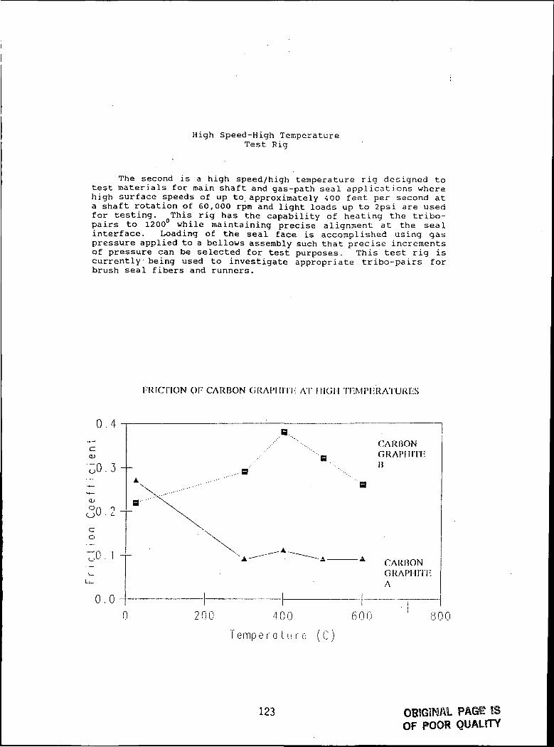
High Speed-High TemperatureTest Rig
The second is a high speed/high temperature rig designed totest materials for main shaft and gas-path seal applications wherehigh surface speeds of up to approximately 400 feet per second ata shaft rotation of 60,000 rpm and light loads up to 2psi are usedfor testing. flThis rig has the capability of heating the tribo-pairs to 1200 while maintaining precise alignment at the sealinterface. Loading of the seal face is accomplished using gaspressure applied to a bellows assembly such that precise incrementsof pressure can be selected for test purposes. This test rig iscurrently being used to investigate appropriate tribo-pairs forbrush seal fibers and runners.
FRICTION QF CARBON GRAI'IIITI' AT HIGH 'IT-MIM-RATURES
0 . 4
<uOr
co
o . o -
CARBONGRAPHITEI)
CARHONGRAPHITI'A
0 200 400 60 i
T emp e r a tu r e (C)
800
123 OBIGWAL PAGE BSOF POOR QUALITY
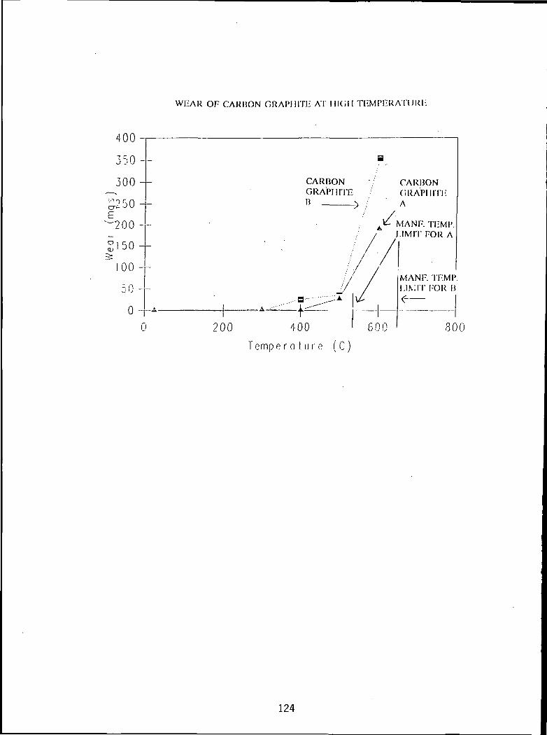
WIIAR OP CARBON GRAPIUTi:-; AT I IKil I THMPEUATUKl-
HUU -
350 -
300-
^250-^E
,
S 1 5 0 -
100 -
50 -
0 -
C
—
A
2C
a
CARBON /GRAPHITEB y
A/l
CARBONGRAPIIITI'A
V1ANF. TliMP./ JJMIT FOR A
///•: / /
••'' / /
/ /...a •^•"Z \£
«, --••"" i---^"T
)0 400 600
MANF. TI-MP.I.IN;IT I-OR n
30
T e m p e r a t u r e ( C )
124
2-15096THE APPLICATION OF DIFFERENTIAL ROUGHNESS
TO MITIGATE FRICTION AND WEAR ;
A. 0. LebeckMechanical Seal TechnologyAlbuquerque, New Mexico
By definition differential roughness occurs where the surface roughness of oneregion is distinctly different (more or less) than that of an adjacent region.Differential roughness may occur on a sliding surface when the structure of anarea of the surface is modified relative to the original material. Differen-tial roughness may be used to effect a film thickness change so as to causehydrodynamic or hydrostatic lubrication effects just as if the surfaces weremachined. The advantage of differential roughness is that the effectiveoffset of film thickness continues to exist even if there is gross wear. Onecan effect film thickness changes which are smaller than can be made directly.Furthermore, asperity tip load support is the same over both the high rough-ness and small roughness regions.
The potential uses for differential roughness are seals, bearings, and pumps.Some examples are presented.
125

N92-15097
SEAL TECHNOLOGY AT ROCKETDYNE
Joe ScharrerAdvanced Rotating Machniery
Rocketdyne's related activities and presentation include:
1. The seal codes currently in use at Rocketdyne and theircapabilities.
2. The seal testing currently planned.
3. The fluid-film bearing activity currently underway and planned,
Rocketdyne Seal Technology
Rocketdyne has a large collection of seal analysis codes
• Floating ring seals
• Static equilibrium• Dynamic response
• Face seals• Steady state performance• Stability analysis
• Load sharing seals
• CFD codes for labyrinth and annular seals• Bulk-flow analysis for rotordynamic coefficients
127 PRECEDING PAGE BLANK NOT FILMED

Rocketdyne Seal Technology
Rocketdyne code development is ongoing
• Barotropic fluid properties
• Phase change
• Brush seal performance
• Large scale roughness
• Asymmetric boundary conditions
Rocketdyne Seal Technology
Rocketdyne has both contract and internal funding for seal testing
• Contract efforts
• AFAL LOX/H2 Turbomachinery Technology ,
• Extraction of rotordynamic coefficients forknurled damping seal in LH2
• Dynamic testing of floating ring seal in LH2
• Dynamic testing of spiral groove face seal in LH2
• NASP
• Extraction of rotordynamic coefficients forknurled damping seal in LQX
• NASA MSFC NRA (with University of Akron)
• Flow visualization and measurement in knurleddamping seal
128
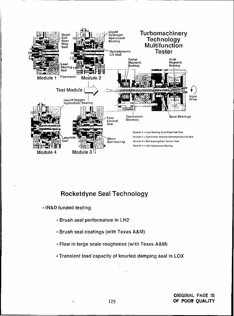
SlatorSoft l.|i|iWearRingSeal
ij-LoadSharing jdSeal
LiquidHydrogenHydrostaticBearing
HydrodynamicLilt Seal
TurbomachineryTechnologyMultifunction
TesterRadialMagneticBearing
AxialMagneticBearing
Module 1 Flexm°unt Module 2
Test Module
Liquid OxygenHydrostatic Bear ng
LabyrinthSeal
TouchdownConlrol BearingsSeal
Slave Bearings
90mmBall Bearing
Module 1 - Load Sharing Seal Slolot Soil Seal
Module 2 = Hydrostatic Bearing'HydrodynDrnlc Lltt Seal
Modulo 3 = Ball Bearing/Face Contact Seal
Module 4 = LOX Hydrostatic Bearing
Module 4 Module 3 I!
Rocketdyne Seal Technology
IR&D funded testing
• Brush seal performance in LH2
• Brush seal coatings (with Texas A&M)
• Flow in large scale roughness (with Texas A&M)
• Transient load capacity of knurled damping seal in LOX
129ORJGiNAl PAGE ISOF POOR QUALITY

Annular Hydrostatic Bearing Transient Tester
System CenteringSupport >
Radial LoadApplicator
AnnularHydrostatic Bearing
Fluid Supply
Dual Ball Bearing Pack
HPOTP PUMP END BEARING CONVERSIONPlans
Design annular LOX hydrostatic bearing/seal• Tapered, knurled sterling silver damping bearing
Eliminate ball bearings No. 1 and No. 2
IR&D to design and fabricate retrofit hardware
Contract to assemble and test on TTB
Design substantiated with component tests in Long Life tester• K-monel and Inconel 718 journals •• 60 start transient simulations per bearing in LOX
Tribometer tests measure friction and wear in GOX
Ignition data provided by White Sands testing
Future plans include upgrading tester to measure coefficients
130

HPOTP PUMP END BEARING CONVERSION
Flight Phase II Configuration Hydrostatic Bearing Retrofit
<$<s ^r=^6g^JJi r-:i;|-
l-Kc^SXl,'-:--- • --^;:;<;;.-:i;,i r.
Twelve parts & bolt pattern removed Replaced by three parts
EXPERIMENTAL VERIFICATION OFROTORDYNAMIC ANALYSIS
MSFC Program Status
Complementary damping bearing development initiated in October• Verifies rotordynamic coefficient calculations for hydrostatic bearings
Tests four hydrostatic bearings in modified long life tester• HCFC test fluid
• Two bearings internally fed through the shaft• Conventional and damping designs TBD
• Two bearings externally fed through the stator• Conventional and damping designs TBD
Extracts all rotordynamic coefficients• Measures leakage and frictional torque
Conceptually designs new HPOTP turbine end package• Includes lowest whirl ratio bearing tested• Provides manufacturing estimate
131 ORIGINAL PAGE ISOF POOR QUALITY

HYDROSTATIC BEARING TECHNOLOGYReview
Problem
• Present turbppumps limited by rolling element bearing life
Goal
• Develop reliable, long life, cryogenic fluid-film bearings
Benefits
• Eliminate rolling element bearing DN limits and life constraints• Add flexibility to optimize rotor mechanical arrangement• Increase damping for more stable operation• Reduce overhauls and maintenance costs
Rocketdyne committed to multiyear IR&D development program
• 1990 expenditure of $1.726M• 1991 commitment of $2.275M
NASA and AFAL contracts in place to further advance technology
HYDROSTATIC BEARING DEVELOPMENT INTEGRATION PLAN
Issue
CodeMaterial
EnvironmentLift-off
CoefficientsTester DemoT/P Demo
Coefficients
T/P Demo
Type/Coeff
T/P Demo
Coefficients
Coefficients
T/P Demo
Task
Code development & verificationMaterial development (tribology)Non-contacting bearing studyTransient life testingCryogenic bearing developmentDual rotor support demonstrationGeneric turbop'imp demo,UK29FD
LOX/Hp MFT bearing development
HPOTP pump end retrofit
Int/ext feed damper brg comparison
HPOTP turbine end retrofit
LOX bearing coef. testing
ADP bearing validation
ADP LH2turbopump
FundingSource
IR&D
AFAL
SSME in&D
MSFC
OPEN
NASP
MSFC
MSFC
FY90
1 2 3 4
Y
LNpi
LN2 Test
FY 91
1 2 3 4
'H2O v' GO? V \
LOX yLN2Test \
LN2 v
IIFC-l3<)a \
FY 92
1 2 3 4
7H20
•'GHo \
7 LH2Test?
^mall Brg. TechA
Vfogt cor
LHg TestingV
HFC-134a V
_T LOX coef.
7 V;
FY93
1 2 3 4
"•002
LOX Test y
7
np
PTest
3t on TTQ
Test comp
TTB Test v
7 LH2 MFT
t comp^
132
92-15098CFD ACTIVITY AT AEROJET
RELATED TO SEALS AND FLUID FILM BEARING
G. E. Bache
This presentation package covers the CFD activity at Aerojet related to sealsand fluid film bearing. The presentation addresses the following topics:
1. Aerovisc Numeric and Capabilities2. Recent Seal Application3. Future Code Development
PRESENTATION PREVIEW
- AEROVISC NUMERICS AND CAPABILITIES
- RECENT SEAL APPLICATION
- FUTURE CODE DEVELOPMENT
133

AEROVISC Numerics
Formulation- Reynolds Stress Averaged Navier-Stokes Equations in Cartesian, Strongly Conservative,
Primitive Variable Form
- k-e and ARS Turbulence Models With Log-Law Wall Functions
Discretization- "Flux" Element Based Finite Volume Method
- General Non-Orthogonal Boundary-Fitted Structured Grid
- Choice of Advection Schemes
• Upward Difference (Most Robust, Least Accurate)
• Mass Weighted Skew (Enhanced Accuracy)
• Linear Profile Skew (Most Accurate)
- Second-Order-Accuracy With Physical Advection Correction Term
-- Rhie-Type Pressure Redistribution for Incompressible Flows
Algebraic Solver
- Choice of Vectorized Gauss-Siedel or Incomplete Cholesky Base Solver
- Additive Correction Multigrid (Large Grids)
- Block Correction (High Aspect Ratio Grids)
RELEVANT CODE CAPABILITIES
INCOMPRESSIBLE FLOW
SUBSONIC, TRANSONIC, AND SUPERSONIC FLOW
NON-ISOTHERMAL AND ISOTHERMAL FLOW
LAMINAR, TURBULENT, OR INVISCID FLOW
CORIOLIS AND CENTRIFUGAL TERMS FOR TURBOMACHINERY APPLICATIONS
FIXED, MOVING OR ROTATING TURBULENT WALLS
CONJUGATE HEAT TRANSFER OR SPECIFIED WALL TEMPERATURE/FLUX
VARIABLE FLUID AND SOLID PROPERTIES
MULTI-COMPONENT FLOW (N ADDITIONAL SCALAR TRANSPORT EQUATIONS)
MULTIPLE BLOCKED REGIONS
134

i . ><nnr • tin
i. "3'ior - LI j
1 2QtSC'Pk3
. . ?7.1ff *00
i ibtit - ua
i . i our • t fn
1.JMUL'UU
9 •'O-JC Cl
n. nitir n i
a s-i-<(- -MI
o ooiir ni
•/. HODL ui
6 a c u c • 0 1
* . i n n r - 0 1
11- ,• 1 H E: f < H 111 fi ti
I . 2 8 7 C ' 0 3
I S^iL'UJ ;
I 1 C 11 • J ;» ;
!1 . 0 a 7 t f * 0 ; ) j
l .US^L'U;* j
•j . Vilb'U2 |
9 .o7ee *J2
a .H-i5e*i)2
7 . o i ? c * a ?
7 . i 7 9 e - n ?
r, s<*£r-n:
b SI Jl- • H.^
S . |U!I- • '..111
-i . tiH'PL • il?
'• . 1)1 '-*fc * ll J
-i 'd B 11- • J _-
:i VIKK • H?
L' . 11-t * J2
i. ^e^t * J1- '
U . UJL'L * Jl j
135 PAGE ISOF POOR QUALITY

Propulsion Division j
L
136 ORIGINAL PAGE fSOF PGOJ? ouAtmr

FUTURE CODE DEVELOPMENT
- GRID EMBEDDING/ATTACHING
- GRID REFINEMENT IN AND NEAR SEALS
- IMPROVED SOLUTION ACCURACY
- MULTI-LAYER TURBULENCE MODEL
AUTOMATED PROCEDURE TO PREDICT FLUID SEALDYNAMIC COEFFICIENTS
137
isOF POOR QUALITY

Perturbation Analysis .
Schematic of Fluid Film Bearing Analysis Methodology
138

92-15099PRATT AND WHITNEY ACTIVITIES
Saadat A. Syed
An example of CFD application in the seal area is described. This effortconsisted of optimizing specific seals in SSME-ATD and resulted in design of aseal tested at Pratt and Whitney which demonstrated 30% lower leakage thanstandard design at the same clearance. This example shows the potential ofidentifying seal geometry parameters which reduce internal flow leakagesdetrimental to component and turbopump efficiencies. This information canthen be used to develop an analytical design procedure for controlling leakagein any given application or environment.
ORGANIZATION
r ~ij:
COMPONENT
DESIGN
PERFORMANCE
PROGRAMMING
GROUP
RESIDENT
CFD
GROUP
GOVERNMENTRESEARCHLABS
SUBCONTRACTORS
TECHNOLOGY TRANSFER- TECHNOLOGY DEVELOPMENT -
139 ORIGINAL PAGf fSOF POOR QUALITY

COMPUTATIONAL FLUID DYNAMICSSignificant Computing Power Available
p&wCRAY X-MP-2/8
SUN
WORKSTATIONS
SiliconGraphics
"IRIS"Workstations
2-D. 3-DGraphics
NASA LeRC
NASA MSFC
APL
NumericalAerodynamic
Simulator(NAS)
NASA ARCCRAY YMP
CFD ANALYSES OF TURBOPUMPSSeven Areas Of Analysis Identified As ImportantFor Successful Turbopump Design
HPFTP
Fuel pump Interstage Turnaround duel/hot gasdlffuser/crossover manifold Interface
Bearings/seals Inlet scroll
HPOTP
Turbine temperature Prebumerredistribution •••"P*«ture
distributionprofile
140

ATP HPFTP INTERNAL FLOW MGMTPump Internal Flows
ATP - HPFTPSeal Detail
141 ORIGINALOF POOR QUAUfV
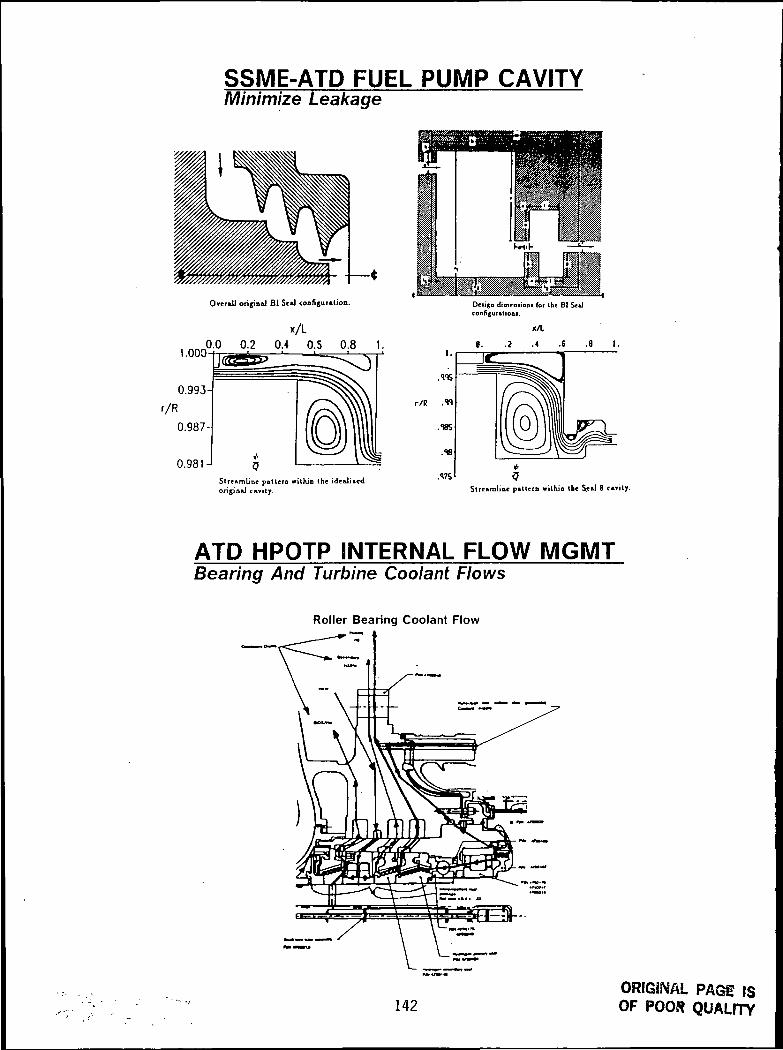
SSME-ATD FUEL PUMP CAVITYMinimize Leakage
Overall original Bl Seal configuration.
x/L
1.0000.0 0.2 0.4 O.S 0.8 1.
0.993-
r/R
0.987-
0.981-1Streamline pat tern within the idcaJizcdorigin*) cavity.
iign di mention i for Ibe BI Sealconfigutttioni.
x/L
.S7SStreamline pa t te rn wi lh io tbe Seal 8 cavity.
ATP HPOTP INTERNAL FLOW MGMTBearing And Turbine Coolant Flows
Roller Bearing Coolant Flow
142ORIGINAL PAGE ISOF POOR QUALITY
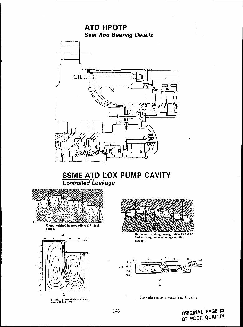
AID HPOTPSeal And Bearing Details
SSME-ATD LOX PUMP CAVITYControlled Leakage
Overall original Interpropellent ( IP ) Sealdesign.
Stietmliae p«IUtl vilkia u idonno.l IP SoJc.nIT
Recommended design configuration for the IPSeal ut i l iz ing the new lealuge liabilityconcept.
Streamline pattern wi th in Seal 75 cavity.
143 PAGE tSOF POOR QUALITY

2-15100
CFD Applications in Propulsion
Charles L. MerkleThe Pennsylvania State University
Department of Mechanical EngineeringUniversity Park, PA 16802
An overview of various applications of CFD algorithms to propulsion problemsis given. Problems of interest include incompressible, low speedcompressible, transonic and supersonic. A common family of algorithms is usedfor all applications and emphasis is placed on maintaining accuracy andconvergence efficiency for all problems. Specific problems include pumphydrodynamics, combustion and mixing simultaneous in rocket engines, viscousnozzle flow, and CFD applications to combustion stability.
CURRENT PROJECTS
ROCKET COMBUSTOR MODELING
COMBUSTION INSTABILITY MODELING
PUMP FLOWFIELDS
VISCOUS NOZZLE/PLUME FLOWS
MAXWELL/NAVIER-STOKES ANALYSIS
AUXILIARY PROPULSION
LOW SPEED COMPRESSIBLE FLOWS
145 PRECEDING PAGE BLANK NOT FILMED
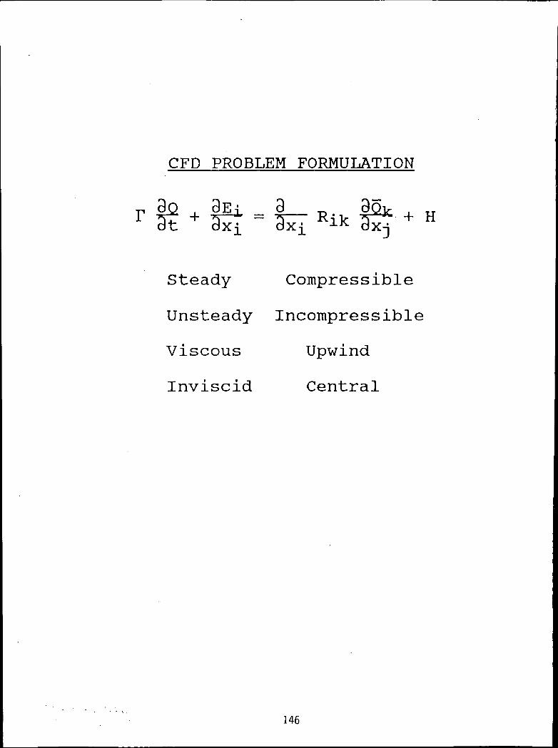
CFD PROBLEM FORMULATION
r gz + £Ei =d Hfikdt dx-[ dxj[ 1K dxj
Steady Compressible
Unsteady Incompressible
Viscous Upwind
Inviscid Central
146
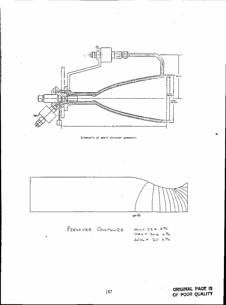
Schematic of small thruscer geometry.
,<.s 4.
147ORIGINAL PAGE ISOF POOK QUALITY

K
1 .0-
0 . 8 -
0 . 6 -
0.4
0.2
0 .0 -
-0.2 0.0 0.2 0.4 0.6 0.8 1.0
148

P Fluct vs. Time Case I Priem i=10l j=51 cll=0.5
.0100 -
.0071
.0043 -
.0014p prime
-.0014 -
-.0043 -
-.0071 -
-.0100 - I I I
Linear
Nonlinear
.00500 .00571 .00643 .00714 .00706 .00857 .00929 .01000time 23 Mnr 91 16:59:49
P Fluct vs. Time Casel Priem i=101 j=51 c(l=0.5
.0100
.0071 -
.0043 -
.0014p prime
-.0014
-.0043 -
-.0071 -
-.0100
Linear
Nonlinear
..00000 .00071 .00143 .00214 .00286 .00357 .00429 .00500time 23 Mar 91 16:59:49
149PAGE IS
OF POOR QUALITY

P Flucl vs. Time Case2 Priem i=101 j=51 cll=0.5
.403
.288
.173 -
.059p prime
-.056
-.171
-.285
-.400
Linear
Nonlinear
.0000 .0026 .0051 .0077 .0102 .0128 .0154 .0179
lime 24 Mar 91 16:16:40
Plunging Airfoi l
150

Wake behind utrc stator/rotor
-40. -30.—i—-20. -10. 0. 10. 20. 30. 40.
. 0: 2.—r—
8. 10. 12.—i—14. 16.
151ORIGINAL PAGE ISOF POOR QUALITY

•30
O O O O O O O O C D OO O O O O C- O '3 O CO O O O O O O O O OO O O O O O O O C O
o — w m -r in 10 r- a -j»
E O <! 4- M )- r-
152 ORIGINAL PAGE 19OF POOR QUALITY

o oo oo oo r>
O — r>
153 OR1G5NAL PAGE ISOF POOR QUALITY
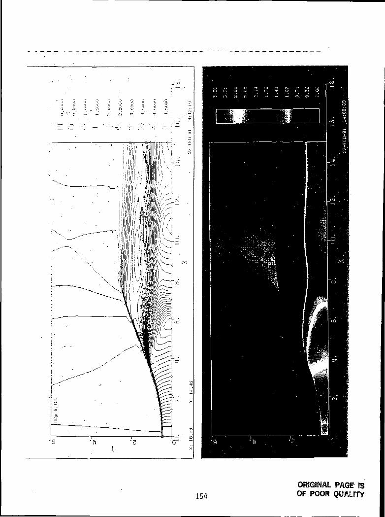
154ORIGINAL PAGT fSOF POOR QUALITY
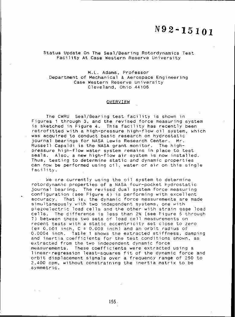
2-15101
Status Update On The Seal/Bearing Rotordynamics TestFacility At Case Western Reserve University
M.L. Adams, ProfessorDepartment of Mechanical & Aerospace Engineering
Case Western Reserve UniversityCleveland, Ohio 44106
OVERVIEW
The CWRU Seal/Bearing test facility is shown inFigures 1 through 3, and the revised force measuring systemis sketched in Figure 4. This facility has recently beenretrofitted with a high-pressure high-flow oil system, whichwas acquired to conduct basic research on hydrostaticjournal bearings for NASA Lewis Research Center. Mr.Russell Capaldi is the NASA grant monitor. The high-pressure high-flow water system remains in place to testseals. Also, a new high-flow air system is now installed.Thus, testing to determine static and dynamic propertiescan now be .performed using o i l , water or air on this singlefaci1i ty.
We are currently using the oil system to determinerotordynamic properties of a NASA four-pocket hydrostaticjournal bearing. The revised dual system force measuringconfiguration (see Figure 4) is performing with excellentaccuracy. That is, the dynamic force measurements are madesimultaneously with two independent systems, one withpiezoelectric load cells and the other with strain gage loadcells. The difference is less than 2% (see Figure 5 through7) between these two sets of load cell measurements onrecent tests with a static eccentricity set close to zero(e= 0.001 inch, C = 0.009 inch) and an orbit radius of0.0004 inch. Table 1 shows the extracted stiffness, dampingand inertia coefficients for the test conditions shown, asextracted from the two independent dynamic forcemeasurements. These coefficients were extracted using alinear-regression least-squares fit of the dynamic force andorbit displacement signals over a frequency range of 250 to2,400 cpm, without constraining the inertia matrix to besymmetric.
155
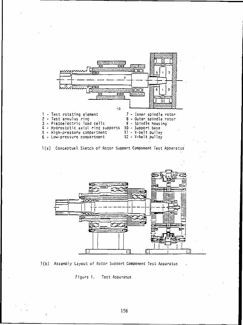
1 - Test rotating element 7 - Inner spindle rotor2 - Test annulus ring 8 - Outer spindle rotor3 - Piezoelectric load cells 9 - Spindle housing4 - Hydrostatic axial ring supports 10 - Support base5 - High-pressure compartment 11 - V-belt pulley6 - Low-pressure compartment 12 - V-belt pulley
l (a ) Conceptual Sketch of Rotor Support Component Test Apparatus
l(b) Assembly Layout of Rotor Support Component Test Apparatus
Figure 1. Test Apparatus
156

Test RigPressureG a u g e Panel
R e l i a n c e2 5 H P DCM o t o r
P i p i n g A r e a(see P i p i n gF i g u r e )
M o t o r 4P u a p
TOP VIEWOS 3 0 H PVarifiriveMotor
1100 Gal .Water Tank
SlidingDoor
-30'5
W a t e r P u m p s «i ianceCon t ro l Box Mi ia f1'13* A r e a
DC M o t o r \ , S w i t c h ( s ee ?i?i.-.sTes t Rig F i g u r e ) ,P ressure
C o n t r o l Box
Cabine t \
T \ \
LDo « O • *
O O O O
0
UTJ
,L-C
\r0
FLOOR
I s o l a t i o nTrans f o r m e r
IBM ir T e a :Rig
U S 2 0 H ?V a r i i. r i v«
* a t e :Tar. ic
FRONT VIEW
Fig. 2. Floor plan and elevation view of cesc fac i l i ty .
157 ORIGINAL PAGE SSOF PQOR QUALITY

DATA
ACQUISITIOlv >AND
PROCESSING
SIGNALCONDITIONING <
WITH MECH. SPVARIATION
I
/
L
PRINTER
HAR:DISH
r/ \ /: / —
i tim rst
FLOPUNIT
/ /30//
IBM <«361MAINFRAME
f. \\ ..
/ Ii\ .]"- KEYBOARD
OLORQNITOR
a CH. A/DEXTCLK. CH.l CH.2 CH.3 CH.4 CH.5 CH.6 CH.7 CH.3
\ -n-r
\
PR
In,™
• [j
X Y Fxk Fyt
PROX. /\ • • /
A -\ A, I
nt 1 h 3' CHG.A. | CHG.
|2 - -CHG.A.
£7"j f
1 L5c=^"xlxj , fyLE-xrx!
U ,
ux* n_,-X- ?<^r ' tPO^
^
i Fxs
1
'\Lj /
4
CHG.A.
'V
Fys ,Ax 'Ay
1
2 3 U
pui . . .35 HP DC VAR. SP.REGENERATIVE MOTOR
DATA ACQUISITION SYSTEM
Fig. 3- Schematic of data acquisition system.
158
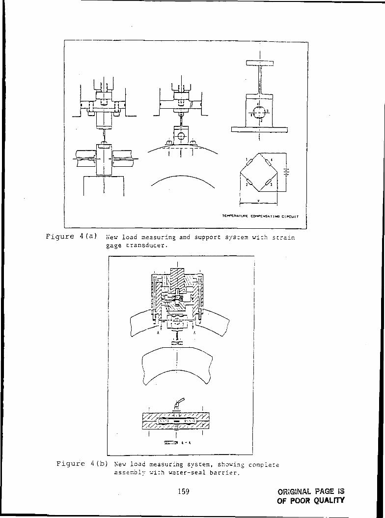
""T ' JI ; I ~JUTSo
«TT
-e-
I
CDr»>ENSaT INQ C I R C U I T
Figure 4 (a) j ew load measuring and support system wigage transducer.
th strain
'
Figure 4 (b) New load measuring system, showing comple t eassembly wi th water-seal bar r ie r .
159 ORJGSNAL PAGE 53OF POOR QUALITY

TOTAL TIME-AVERAGED SIGNAL (50 cycles)
+30,00m
10. I_ lUJU
O -
I —
UIIIilloNUJa.
o
UJUn: -Oui
-30,00
jiiiijIe-Pe'aK Ami ilil« * lo nr id T'liaso
Angle of Pout ier Fiixlainonlal Tei in
2O.30 I LOr
-2-1.109 DEGREE
V\
0,^=1.000 RPM
0^=675 CPM
368
TOTAL TIME-AVERAGED SIGNAL (50 cycles)
+30,00
m
U) -_iUJuUJ -QOJ_
cri-co
£O ~
"
UJuo ~u.I
-Ifl flflOU i vv
(
^~—
}
""— \
\"\
\
"\
\
\
\
<j =1.0OO RPM""
ncn)I[=G75 CPM
p =75 pS1()
Tllvll
Single-Peak Amplitude and Phase
Angle of Fourier Fundamental Teim :
20.005 LBF
-25.736 DEGREE
\
i/
f
J\._ /
\_ /""~\ /~
I C.ir cjl-IE I"'L-:RIOD
__/
•
////
360
160 ORIGINAL PAGE ISOF POOR QUALITY

FIRST TERM OF FOURIER DECOMPOSITION
CO
UJo
LLI
-18 -
TIME <~>F ONL" PERIOD3GQ
DYNAMIC COEFFICIENTS PEPOPT
SPECIAL FILENAME IS : CCF. IMP
TOTAL INPUT FS DATA FILE IS : 10
SHAFTSFEED CP.Ptli IS : 10OO
PECESS PRESSURE iPSIi IS : 75
INPUT DATA FILENAME NO. OF CYCLE ORBIT FREQUENCY <;F:PM.>
: c i :••:c2FCC3F:C4F:C5FI C£F:C7F:CSFICSF:.cn:
.FS
.FS
.FS
.FS
.FS
.FS
.FS
.FS
.FSF.FS
1 2471 3631 47£
1 5631 6771 7£51 . 3711 1 O4 11 1 1331 1247
ROTOPDYNAMIC COEFFICIENTS :
CK:i:D LB/INCH
0. 13236Z'E+Ci£ O. 3'E'£07OE+05
-. 44i42£E+C'5 0. 124S12E-t-0£
cck: LB*SEC/:NCH
O. fi^S'SiSE+OS -. 2444'54E+03
O. 1O104-3E+O3 O.'334374E+':i3
CDI: ] LB»SEC»SEC/INCH
-. 142564E*O1 -.213640E-1-01
0. 189671 E-t-01 -. 607746E+00
C K s ]
0. 127'i23E+06 0. 4700S"TE-1
-.47037SE-I-05 O.!321£3E^
C C s ]
0.652728E-03 -.303505E<
0. 97S187E-»-02 O. 'PSlOtSE-i
C D s ]
-. 15-3256E+01 -.256475E-I
0.201067E+01 -.499795E-
•01
•00
Table 1 (a )
161ORSGINAl PAGE ISOF POOR QUALITY

DYNAMIC COEFFICIENTS REPORT
SPECIAL FILENAME IS : IIF.INP
TOTAL INPUT FS DATA FILE IS : 10
SHAFTSPEED (RPM.i IS : 2OOO
RECESS PRESSURE fpSIJ IS : 75
INPUT DATA FILENAME NO. OF CYCLE ORBIT FREQUENCY
I I 1F.FSII2F.FSI I3F.FSII4F.FSII5F.FSII6F.FSII7F.FSIIBF.FSII9F.FSI I1OF.FS
1 2841 5o31. •• 7751 9791 1 131! 12771 1 57^1 17331 21351 2375
ROTQRDYNAMIC COEFFICIENTS:
cKk] LB/INCH
O. 136&5BE+06 0.74O254E+05
-.363&57E*05 0. 139754E-K>6
C C k 3 LB»SEC/INCH
0.501801E+03 0. 114119E+O3
-.192731E+03 0.8713BOE+O3
CDI :3 LB»SEC*SEC/INCH
0. E.6OO29E-01 -. 30450SE + 00
0. 7672£7E-K>0 0. 7544'3'3E+OO
CI.5]
0.126282E+06 0.739171E-05
-.33'Jl 12E+05 0. i33£41E+<:'£
CCs]
0.44S336E»O3 O.104627E*03
-.2O639£E-K'3 0. 874430E-^03
CDs]
O. 730574E-01 -. 1-4O757E-MJO
0. 82550 7E+OO '.''. 314Sb3E-*00
Table 1 (b)
162 ORIGINAL PAGE ISOF POOR QUALITY

2-151Q2
SEAL TEST PROGRAM AT MIT
Manual Martinex-Sanchez and K.T. Millsaps, Jr.Massachusetts Institute of Technology
MIT reports on a seal test program that was conducted in a dynamic rig. Fourdifferent 1-gland labyrinths were tested. The eccentricity, spin rate, whirlrate and flow ere varied independently.
163

92-15103
NATIONAL AEROSPACE PLANE ENGINE SEALSHigh Temperature Seal Performance Evaluation
Bruce M. SteinetzNASA Lewis Research Center
Key to the successful development of the single-stage-to-orbitNational Aerospace Plane (NASP) is the successful development ofcombined cycle ramjet/scramjet engines that can propel the vehicleto 17,000 mph to reach low earth orbit. To achieve engineperformance over this speed range, movable engine panels are usedto tailor engine flow that require low-leakage high-temperatureseals around their perimeter. NASA Lewis is developing a family ofnew high temperature seals to form effective barriers againstleakage of extremely hot (>2000 °F), high pressure (up to 100 psi)flow path gases containing hydrogen and oxygen. Preventingbackside leakage of these explosive gas mixtures is paramount inpreventing the potential loss of the engines or the entire vehicle.
Described in the subsequent pages of this report are sealtechnology development accomplishments in the three main areas ofconcept development, test and evaluation and analyticaldevelopment. The presentation closes with a brief discussion offuture plans.
SEAL CONCEPTS UNDER DEVELOPMENT (U)
CERAMIC WAFER SEAL BRAIDED CERAMIC ROPE SEAL
METALILUOWS
f••'- OPIIOKU.
COOllOrtuisunuiDMIIU IIUOWI
UNCLASSIFIED
165
PRECEDING PAGE BLANK NOT FILMEDORSGiNAlOF POOR QUALJfV

SUMMARY OF TECHNOLOGY DEVELOPMENT
SEAL DEVELOPMENT;o ADVANCED CONCEPT DEVELOPMENT
o FABRICATION TECHNOLOGY
ANALYTICAL DEVELOPMENT:o SEAL LEAKAGE FLOW MODELING
o THERMAL-STRUCTURAL ANALYSES
EXPERIMENTAL DEVELOPMENT AND EVALUATION:o HIGH TEMPERATURE LEAKAGE PERFORMANCE EVALUATION
o HIGH TEMPERATURE FRICTION AND WEAR ASSESSMENTSSOLID FILM LUBRICANT DEVELOPMENT
t-AXIAL\ PRELOAD\ ^
SCHEMATIC OF HIGH-TEMPERATURE PANEL-EDGE SEAL RIG (U)
/-*\ -x^^T") **, i
ADJUSTABLE LATERALPRELOAD SYSTEM^-,.
.\x
/
-AXIAL PRELOAD
STATIC PRESSURE ANDTEMPERATURE PROBES-,
- . . . /
CANDIDATE TEST SEAL
MULTIPLE PRELOADBELLOWS
rO.150" DISTORTION^ 18" SPAN
,,,,_ r-™c /BELLOWS- '
HIGH \ \WATT-DEHSITY \\SURFACE HEATERS^
//" —^"tu.
i ' <?FPTinM... ^-INTERCHANGEABLE STRAIGHT °±y"u"
S1^ AND DISTORTED WALLS ^ " "
4.GH-TEMPERATURE HEAD ^&£$™GASKET EXCHANGER) '"AUIIMMUtnj
1500 °f PRESSURIZED AIR(LEAKAGE METERED UPSTREAM)
166
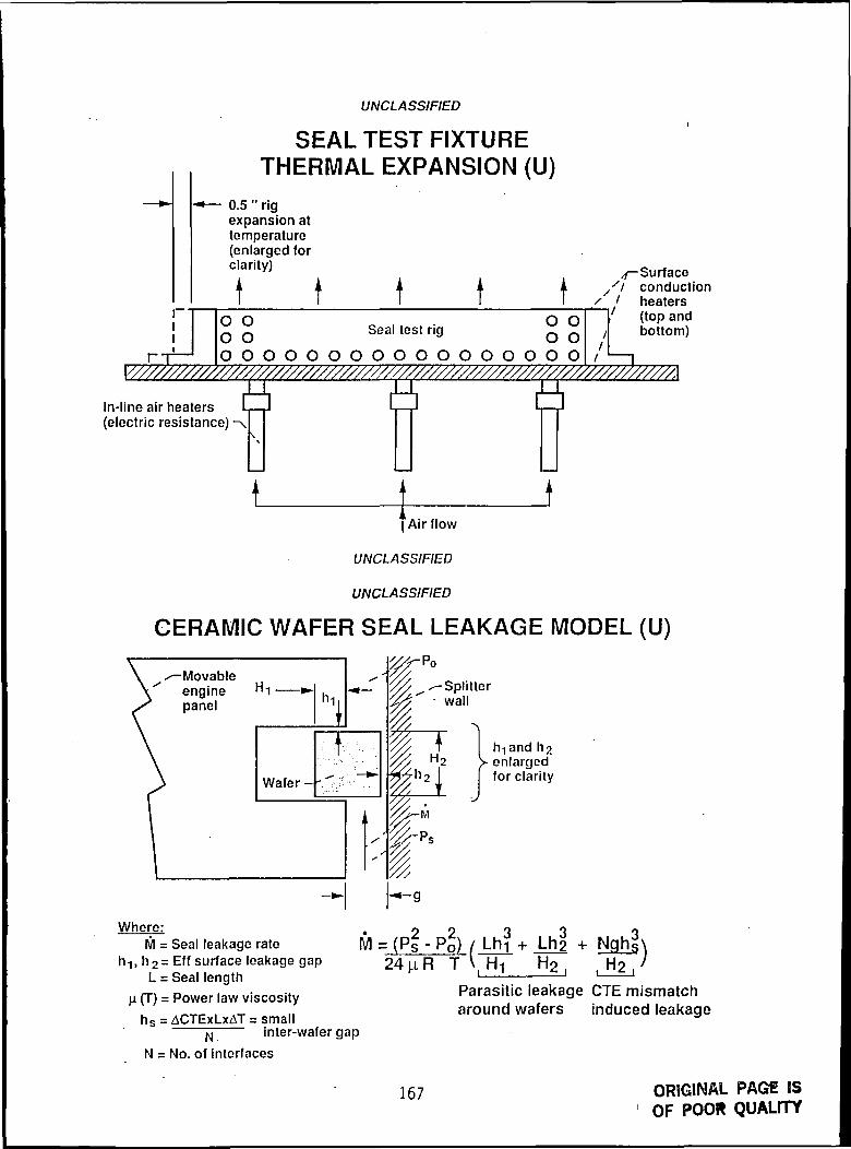
UNCLASSIFIED
SEAL TEST FIXTURE
.. ».
111
• • • m^ m » • • •
•^ — 0.5 " rigexpansion attemperature(enlarged forclarity)
t t0 0O 0
I-T— o o o o o o
m m am •»•« « • • » •
tSeal test rig
O O O O O
v ^^ • ^^ • v 1 ^ *
i — Pi irfnr
t i xx/ condu
1 .x / heaterO 00 0
o o o o o o
' (top a/ botton
'f I
In-line air heaters(electric resistance)
Airf low
UNCLASSIFIED
UNCLASSIFIED
CERAMIC WAFER SEAL LEAKAGE MODEL (U)
-Movableenginepanel 1|
Wafer-
Po
-Splitterwall
]> enlarged[ for clarity
Where:M = Seal leakage rate
h-), h2= Eff surface leakage gapL = Seal length
H (T) = Power law viscosityhs = ACTExLxAT = small
ft inter-wafer gap
N = No. of interfaces
• 2 2M = (Ps - ~- PQ) / Lhi + Lh2 •*- Nghg\
24j.iR T \ H! H2| H2/Parasitic leakage CTE mismatcharound wafers induced leakage
167 ORIGINAL PAGE ISOF POOR QUALITY

COMPARISON OFMEASURED AND PREDICTED LEAKAGE RATES VS TEMP.
FIXED PRESSURE DIFFERENTIAL: 40 psi
5x10°
3o>C •
O MeasuredPredicted
Tentative leakage limit
200 400. GOO' 800 1000
Temperature, F '
1200 1400
PRESSURE INDUCED WAFER LOADS
PRESSURE DISTRIBUTION:
Movableengine , I I j (
panel —, ~ ^^'
P.-' -— Splitter wall
( x )
'-"1-
FORCE BALANCE:
T - T *d«fp2 p2\
Pressure proHles: P, (y) - (P0 * u " >
Bcsullanls:
Resultant loads
(H'-H,3) _±M!-^SJ (H2J-H,S
' ' I K i 2 '
168

UNCLASSIFIED
2-D BRAIDED ROPE SEAL LEAKAGE PERFORMANCE (U)ROOM TEMPERATURE AIR, 80 PSI PRELOAD
Mass flow(Ib/ft.-sec.)
.000
.006
.004
.002
DA-1OB-1Ac-1,<2>D-1OE-1• F-1+ G-1AH-1
04530104530104530
% Long3535355555557575
Tentative leakage
limit
= 60 psi
1000 2000 3000 4000 5000 6000
UNCLASSIFIED
BRAIDED ROPE SEAL LEAKAGE MODEL (U)
Movableenginepanel -
Splitterwall
I-Sheath
M =L R R
/EffSeal VVResistance/
_!_+_!_ + .
Ri R2 R4 Rs+Re+R?
Where:M/L = Seal leakage per unit length
Rl, R2 = Resistance to flow behind and in-front of sealR3i R4 = Sheath resistance (eg parallel to flow direction)RS, R7 = Sheath resistance (eg perpendicular to flow direction, upstream and downstream)
R = Core resistance
169

UNCLASSIFIED
BRAIDED ROPE SEAL LEAKAGEMEASURED AND PREDICTED (U)
.008
.006
Flowrate .004
Ib/s-ft
.002
.000
Sample A1Room temperature air,
80 psi preload
D MeasuredPredicted
Sample G1Room temperature air,
80 psi preload
D Measured
Predicted
0 10 20 30 40 50 0 10 20 30 40 50 60 70
Pressure drop (psi)
SEAL DEVELOPMENT FUTURE PLANS
o EVALUATE ALTERNATE FIBER TOW DURABILITY OVER SIMULATEDTEMPERATURES.
o EVALUATE COMBINED DURABILITY/LEAKAGE PERFORMANCE OF ADVANCEDBRAID ARCHITECTURES UNDER ENGINE SIMULATED SLIDING CONDITIONS,TEMPERATURES AND PRESSURES.
o EVALUATE SURVTVABILITY OF BRAIDED ROPE SEALS UNDER THE ENGINESIMULATED EROSIVE SUPERSONIC FLOW FIELD.
EXPERIMENTALLY ASSESS REQUIRED TRANSPIRATION COOLANT FLOW RATESTO SURVIVE THE HIGH ENGINE-SIMULATED HEAT FLUXES.
170
N92-15104VOLUME VISUALIZATION AND KNOWLEDGE INTEGRATION
Thomas CochraneYosemite Systems, Inc.
Mr. Cochrane discusses how advanced computer graphics visualization techniquesand integration of knowledge throughout the concept to production cycle areproviding tools to revolutionize the design process. Relevant projects thatare used as examples are at USAF, Ford, Digital, EPA and DOE.
171

2-15105
FLUID SEALS TECHNOLOGY AT BHR GROUP LTD.
Simon LeefeBHR Group Ltd.
A mathematical model has been developed by BHR Group (formerly the BritishHydromechanics Research Association) for the European Space Agency. The modelcouples the rigid body dynamics in four degrees of freedom of a flexibly-mounted stator (with Coulomb damping) of a turbopump face seal with the fluidfilm behavior. The interfacial film is assumed gaseous, and the modelincorporates laminar/turbulent flow, inertia and sonic choking. Seal facesmay be wavy and coned, whilst the rotating ring can be eccentrically mounted,misaligned with the shaft and oscillate axially at arbitrary frequency. Themodel is currently being coded into software. An experimental programme usinga high speed cryogenic/hot gas test rig is being conducted to verify theoutput of the computer program. Future work planned for later in the yearwill incorporate mechanical contact effects.
173 PRECEDING PAGE BLANK NOT FILMED
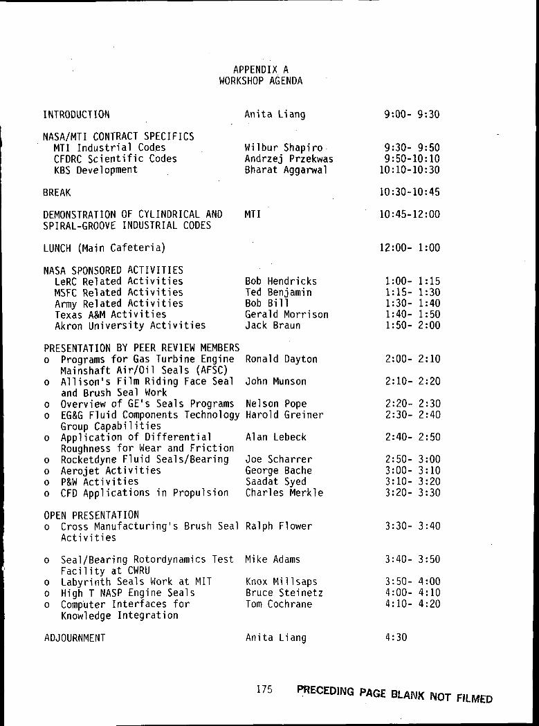
APPENDIX AWORKSHOP AGENDA
INTRODUCTION
NASA/MTI CONTRACT SPECIFICSMTI Industrial CodesCFDRC Scientific CodesKBS Development
BREAK
DEMONSTRATION OF CYLINDRICAL ANDSPIRAL-GROOVE INDUSTRIAL CODES
LUNCH (Main Cafeteria)
NASA SPONSORED ACTIVITIESLeRC Related ActivitiesMSFC Related ActivitiesArmy Related ActivitiesTexas A&M ActivitiesAkron University Activities
PRESENTATION BY PEER REVIEW MEMBERSo Programs for Gas Turbine Engine
Mainshaft Air/Oil Seals (AFSC)o Allison's Film Riding Face Seal
and Brush Seal Worko Overview of GE's Seals Programso EG&G Fluid Components Technology
Group Capabilitieso Application of Differential
Roughness for Wear and Frictiono Rocketdyne Fluid Seals/Bearingo Aerojet Activitieso P&W Activitieso CFD Applications in Propulsion
Anita Liang
Wilbur ShapiroAndrzej PrzekwasBharat Aggarwal
MTI
Bob HendricksTed BenjaminBob BillGerald MorrisonJack Braun
Ronald Dayton
John Munson
Nelson PopeHarold Greiner
Alan Lebeck
Joe ScharrerGeorge BacheSaadat SyedCharles Merkle
OPEN PRESENTATIONo Cross Manufacturing's
ActivitiesBrush Seal Ralph Flower
o Seal/Bearing Rotordynamics TestFacility at CWRU
o Labyrinth Seals Work at MITo High T NASP Engine Sealso Computer Interfaces for
Knowledge Integration
ADJOURNMENT
Mike Adams
Knox MillsapsBruce SteinetzTom Cochrane
Anita Liang
9:00- 9:30
9:30- 9:509:50-10:1010:10-10:30
10:30-10:45
10:45-12:00
12:00- 1:00
1:00- 1:151:15- 1:301:30- 1:401:40- 1:501:50- 2:00
2:00- 2:10
2:10- 2:20
2:20- 2:302:30- 2:40
2:40- 2:50
2:50- 3:003:00- 3:103:10- 3:203:20- 3:30
3:30- 3:40
3:40- 3:50
3:50- 4:004:00- 4:104:10- 4:20
4:30
175 PRECEDING PAGE BLANK NOT FILMED

APPENDIX BWORKSHOP ATTENDANCE LIST
Mike AdamsCase Western Reserve University
Bharat AggarwalMechanical Technology, Inc.
Mahesh AthavaleCFD Research Corp.
Carlos BaileyTurbo Components Textron
Theodore BenjaminNASA MSEC
Bob BillU.S. Army
Marc Carpi noPenn Statue University
Tom CochraneYosemite Systems, Inc.
Ron DaytonU.S. Air Force
Hung M. DoDresser-Rand
T. I. EldridgeStein Seal Company
Rob EvensonNOVA Corporation of Alberta
Ralph FlowerCross Manufacturing
Sol GorlandNASA LeRC
Alston GuAllied Signal Aerospace Co.
George HosangSundstrand Power Systems
Albert KascakUS Army
Gene AddyNASA LeRC
Antonio ArtilesMechanical Technology, Inc.
George BacheAerojet
Prithwish BasuEG&G Fluid Components Technology
Donald BentlyBently Nevada Corporation
Jack BraunAkron University
F. K. ChoyAkron University
Ray ChuppTeledyne CAE
Florin DimofteNASA LeRC
Constance DowlerU.S. Air Force
John EppehimerStein Seal Company
Frank FerlitaPratt & Whitney
Jim GardnerEG&G Fluid Components Technology
Harold GreinerEG&G Fluid Components
Bob HendricksNASA LeRC
Gene JacksonRocketdyne
John KocurPratt & Whitney
177PRECEDING PAGE BLANK NOT FILMED

Sunil B. KulkarniDurametallic
Anita LiangNASA LeRC
Mark MakhobeyCar-Graph, Inc.
Alan D. McNickleStein Seal Company
K. T. MillsapsMIT .
Bahram Z. MovahedSundstrand Corporation
Agnes MuszynskaBentley Nevada Corporation
Mike O'BrienComponent Engineering
Bart OlsonSparta Inc.
Bruce S. PlaceMagnetic Seal Corporation
Margaret ProctorNASA LeRC
Steve RiddlebaughNASA LeRC
James SaundersBattelle
Joe ScharrerRocketdyne
Stephen ShamrothScientific Research
Ashok SinghalCFD Research Corp.
Bruce SteinetzNASA LeRC
Dan B. Van FossenFinite Element Technology Corp.
Alan 0. LebeckMechanical Seal Technology
Robert G. LoewenthalEG&G Fluid Components Technology
Manual Martinez-SanchezMIT
Charles MerkleThe Pennsylvania State University
Gerald MorrisonTexas A&M University
John MunsonAllison Gas Turbine
Chuck NevolaEG&G SEALOL
Jim O'DonnellNAVAL Air Propulsion Center
Glenn PechtJohn Crane, Inc.
Nelson PopeGeneral Electric
Andrzej PrzekwasCFD Research Corp.
Norman SamurinDresser-Rand
Marshall SavilleAllied-Signal Aerospace Co.
Julie SchlumbergerNASA LeRC
Wilbur ShapiroMechanical Technology, Inc.
Paul Si rockySverdrup
Saadat A. SyedPratt & Whitney
Manik VasagarKaydon Ring & Seal, Inc.
178

Joe Veres Jim WalkerNASA LeRC NASA LeRC
David Westcott Mark WilsonPratt & Whitney Allison Turbine Division
179

REPORT DOCUMENTATION PAGEForm Approved
OMB No. 0704-0188Public reporting burden lor this collection of information is estimated to average 1 hour per response, including the time for reviewing instructions, searching existing data sources,gathering and maintaining the data needed, and completing and reviewing the collection of information. Send comments regarding this burden estimate or any other aspect of thiscollection of information, including suggestions for reducing this burden, to Washington Headquarters Services, Directorate for information Operations and Reports, 1215* JeffersonDavis Highway, Suite 1204, Arlington, VA 22202-4302, and to, the. Office of Management and Budget, Paperwork Reduction Project (0704-0188), Washington, DC 20503.
1. AGENCY USE ONLY (Leave Wan*) 2. REPORT DATE* 3. REPORT TYPE AND DATES COVERED
March 1991 Conference Publication4. TITLE AND SUBTITLE
Seals Flow Code Development .
6. AUTHOR(S)
7. PERFORMING ORGANIZATION NAME(S) AND ADDRESS(ES)
National Aeronautics and Space AdministrationLewis Research Center
. Cleveland, Ohio 44135-3191
9. SPONSORING/MONITORING AGENCY NAMES(S) AND ADDRESS(ES)
National Aeronautics and Space AdministrationWashington, D.C. 20546-0001
5. FUNDING NUMBERS
WII ^Ofi &T> 79
8. PERFORMING ORGANIZATIONREPORT NUMBER
E-6219
10. SPONSORING/MONITORINGAGENCY REPORT NUMBER
NASA CP- 10070
11. SUPPLEMENTARY NOTES
Responsible person, Anita Liang, (216) 433-8779.
12a. DISTRIBUTION/AVAILABILITY STATEMENT
Unclassified - UnlimitedSubject Categories 16 and 99
12b. DISTRIBUTION CODE
1 3. ABSTRACT (Maximum 200 words)
In recognition of a deficiency in the current modeling capability for seals, a seven-year effort was established in 1990by NASA's Office of Aeronautics, Exploration, and Technology under the Earth-to-Orbit Propulsion program of theCivilian Space Technology Initiative to develop verified computational-fluid-dynamic (CFD) concepts, codes, andanalyses for seals. The objectives were to develop advanced concepts for the design and analysis of seals, to effec-tively disseminate the information to potential users by way of annual workshops, and to provide experimentalverification for the models and codes under a wide range of operating conditions. The first annual workshop on"Seals Flow Code Development" was conducted at the NASA Lewis Research Center in Cleveland, Ohio, onMarch 26, 1991. The purpose was to report the progress of this program and to provide a forum for informationexchange with the potential end-users. The presented material is documented in the NASA Proceedings.
14. SUBJECT TERMS 15. NUMBER OF PAGESComputational fluid mechanics; Mathematical models; Turbomachinery; Pump seals; 183Expert systems; Dynamics 16. PRICE CODE
A09
17. SECURITY CLASSIFICATION 18. SECURITY CLASSIFICATION 19. SECURITY CLASSIFICATION 20. LIMITATION OF ABSTRACTOF REPORT OF THIS PAGE OF ABSTRACT
Unclassified Unclassified Unclassified
NSN 7540-01-280-5500
C-3
Standard Form 298 (Rev. 2-89)Prescribed by ANSI Std. Z39-18298-102

National Aeronautics andSpace Administration
Lewis Research CenterCleveland, Ohio 44135
Official BusinessPenalty for Private Uae $300
FOURTH CLASS MAIL
ADDRESS CORRECTION REQUESTEDU.S.MAIL
Post?ge and Fees PaidNational Aeronautics andSpace AdministrationNASA 451
NASA