seapress - viega
TRANSCRIPT

Instructions for Use
Seapress
Press connector system made of CuNi10Fe1.6Mn alloy.
System Year built (from)Seapress 03/2003
INT

Table of contents
1 About these instructions for use 3
1.1 Target groups 31.2 Labelling of notes 31.3 About this translated version 4
2 Product information 5
2.1 Standards and regulations 52.2 Intended use 6
2.2.1 Regulations 62.2.2 Areas of use 72.2.3 Media 7
2.3 Product description 82.3.1 Overview 82.3.2 Pipes 82.3.3 Press connectors 102.3.4 Sealing elements 11
2.4 Information for use 132.4.1 Corrosion 13
3 Handling 14
3.1 Transport 143.2 Storage 143.3 Assembly information 14
3.3.1 Mounting instructions 143.3.2 Potential equalisation 153.3.3 Permitted exchange of sealing elements 153.3.4 Space requirements and intervals 163.3.5 Required tools 18
3.4 Assembly 193.4.1 Replacing the sealing element 193.4.2 Bending pipes 203.4.3 Shortening the pipes 203.4.4 Deburring the pipes 213.4.5 Pressing the connection 223.4.6 Leakage test 23
3.5 Disposal 23
Table of contents
Seapress 2

1 About these instructions for use
Trade mark rights exist for this document; for further information, go toviega.com/legal.
1.1 Target groupsThe information in this manual is directed at heating and sanitary pro‐fessionals and trained personnel.
Individuals without the abovementioned training or qualification are notpermitted to mount, install and, if required, maintain this product. Thisrestriction does not extend to possible operating instructions.
The installation of Viega products must take place in accordance withthe general rules of engineering and the Viega instructions for use.
1.2 Labelling of notesWarning and advisory texts are set aside from the remainder of the textand are labelled with the relevant pictographs.
DANGER! This symbol warns of possible life-threatening injury.
WARNING! This symbol warns of possible serious injury.
CAUTION! This symbol warns of possible injury.
NOTICE! This symbol warns of possible damage to property.
This symbol gives additional information and hints.
About these instructions for use
Seapress 3

1.3 About this translated versionThis instruction for use contains important information about the choiceof product or system, assembly and commissioning as well as intendeduse and, if required, maintenance measures. The information about theproducts, their properties and application technology are based on thecurrent standards in Europe (e.g. EN) and/or in Germany(e.g. DIN/DVGW).
Some passages in the text may refer to technical codes in Europe/Germany. These should serve as recommendations in the absence ofcorresponding national regulations. The relevant national laws, stand‐ards, regulations, directives and other technical provisions take priorityover the German/European directives specified in this manual: Theinformation herein is not binding for other countries and regions; as saidabove, they should be understood as a recommendation.
About these instructions for use
Seapress 4

2 Product information
2.1 Standards and regulationsThe following standards and regulations apply to Germany / Europe andare provided as a support feature.
Scope / Notice Regulations applicable in Ger‐many
Planning of pipeline installations DIN 86003, Part 1
Scope / Notice Regulations applicable in Ger‐many
Execution and manufacture ofpermitted pipes
DIN 86019
Exact calculation of the fixingpoints
DIN 86082:2008-02
Scope / Notice Regulations applicable in Ger‐many
Field of application of sealing ele‐ments in fire extinguishing and fireprotection systems, foam andsprinkler systems, bilge and bal‐last systems, sea water andcooling water systems
DIN 86003-1
Field of application of sealing ele‐ments in fire extinguishing and fireprotection systems, foam andsprinkler systems, bilge and bal‐last systems, sea water andcooling water systems
DIN 86076
Field of application of sealing ele‐ments in fire extinguishing and fireprotection systems, foam andsprinkler systems, bilge and bal‐last systems, sea water andcooling water systems
Manufacturer's information
Regulations from section: Regulations
Regulations from section: Pipes
Regulations from section: Sealing elements
Product information
Seapress 5

Scope / Notice Regulations applicable in Ger‐many
Corrosion of metals in sea waterand marine applications
DIN 81249-1
Corrosion of metals in sea waterand marine applications
DIN 81249-2
Corrosion of metals in sea waterand marine applications
DIN 81249-3
Corrosion of metals in sea waterand marine applications
DIN 81249-4
Scope / Notice Regulations applicable in Ger‐many
Leakage test in ship pipelines DIN 86001:2010-09
Leakage test in ship pipelines Standard pressure tests of theoperating company (shipyard)
Leakage test in ship pipelines Requirements / regulations of theresponsible classification body/bodies
2.2 Intended use
Coordinate the use of the system for areas of use andmedia other than those described with the Viega ServiceCenter.
2.2.1 RegulationsWhen planning pipeline installations, the regulations applicable for therespective type of vessel must be observed.
Observe for instance the requirements defined by:
n Classification societiesn IMOn SOLASn Marpoln The respective flag state,
for instance the See-Berufsgenossenschaftn Standardsn Equipment manufacturersn Building regulations
Regulations from section: Corrosion
Regulations from section: Leakage test
Product information
Seapress 6

n Pressure equipment directivesn UVV Seen US Coast Guardn Regulations for the Suez Canaln Regulations for the Panama Canal
See also Ä ‘Regulations from section: Regulations’ on page 5
2.2.2 Areas of useSeapress cannot only be used with aggressive media (e. g. sea water),but also in aggressive surroundings (e. g. on ships or in marine engi‐neering systems).
In accordance with the classification criteria and the rating of the classIII of the IACS, the equipment can be used amongst others in the fol‐lowing areas:
n Fire extinguishing and fire protection systemsn Foam and sprinkler systemsn Bilge and ballast systemsn Saltwater cooling systemsn Saltwater desalination systemsn Low-pressure steam systems (only with FKM sealing element)n Condensation removaln Deck and sanitary drainage pipelines (internal)n Scupper and drainpipen Compressed air pipelines (operating air, no starting or control air)
2.2.3 MediaThe system is suitable for the following media, amongst others:
n Saltwatern All types of process watern Compressed air (operating air) in acc. with the specification of the
sealing element usedn EPDM at oil concentration < 25 mg/m3
n FKM at oil concentration ≥ 25 mg/m3
n Fuelsn Lubricantsn Hydraulic fluidsn Steam in low-pressure steam systems (only with FKM sealing ele‐
ment)n Spring and ballast watern Distilled water
NOTICE! Before installation, refer to the relevant valid certificate forverification of suitability and approval, or contact theappropriate certification body.
Product information
Seapress 7
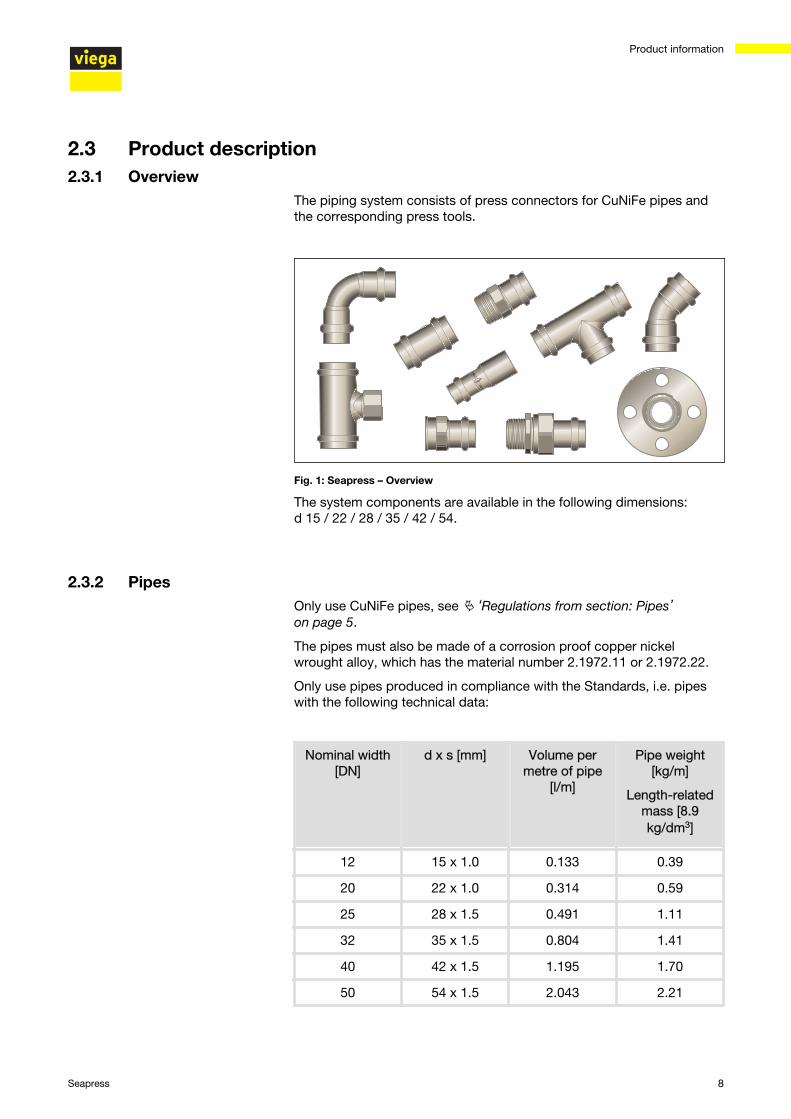
2.3 Product description2.3.1 Overview
The piping system consists of press connectors for CuNiFe pipes andthe corresponding press tools.
Fig. 1: Seapress – Overview
The system components are available in the following dimensions:d 15 / 22 / 28 / 35 / 42 / 54.
2.3.2 PipesOnly use CuNiFe pipes, see Ä ‘Regulations from section: Pipes’on page 5.
The pipes must also be made of a corrosion proof copper nickelwrought alloy, which has the material number 2.1972.11 or 2.1972.22.
Only use pipes produced in compliance with the Standards, i.e. pipeswith the following technical data:
Nominal width[DN]
d x s [mm] Volume permetre of pipe
[l/m]
Pipe weight[kg/m]
Length-relatedmass [8.9kg/dm3]
12 15 x 1.0 0.133 0.39
20 22 x 1.0 0.314 0.59
25 28 x 1.5 0.491 1.11
32 35 x 1.5 0.804 1.41
40 42 x 1.5 1.195 1.70
50 54 x 1.5 2.043 2.21
Product information
Seapress 8

Requirements for fixing intervals should restrict the number of fixingpoints to a technically justifiable amount, on the other hand, they shouldprevent intervals being so large as to cause damage due to vibrations.
The intervals for the fixing pipelines contained in following table are rec‐ommended for the fixing of pipelines:
Interval between the pipe clamps
d [mm] Fixing interval between the pipeclamps [m]
15.0 1.20
22.0 1.20
28.0 1.20
35.0 2.20
42.0 2.20
54.0 2.20
Information on the accurate calculation of the fixing pointsis comprised in the Standard, see Ä ‘Regulations fromsection: Pipes’ on page 5.
Pipelines expand with heat. Heat expansion is dependent on the mate‐rial. Changes in length lead to tension within the installation. These ten‐sions must be equalised with suitable measures.
The following are effective:
n Fixed and gliding pointsn Expansion equalisation joints (expansion bends)
Heat expansion co-efficients CuNiFe
Material Heat expansion co-effi‐cient ⍺
[mm/mK]
Example:
Length expansion withpipe lengths = 20 m and
ΔT = 50 K [mm]
CuNiFe 0.017 17.0
Laying and fixing pipes
Length expansion
Product information
Seapress 9

Fig. 2: Length expansion of CuNiFe pipes
1 - Length expansion → ΔI [mm]2 - Pipe length l0 [m]3 - Temperature difference → Δϑ [K]
2.3.3 Press connectorsPress connectors are available in a number of shapes. An overview ofthe press connectors suitable for the system can be found in the cata‐logue.
The press connectors in the Seapress system are made of the alloyCuNi10Fe1.6Mn, a copper-nickel-iron alloy. This alloy fulfils the specialrequirements for saltwater applications.
Product information
Seapress 10

The press connectors have a circumferential bead in which the sealingelement lies. The press connector is deformed upstream and down‐stream of the bead and permanently connected to the pipe duringpressing. The sealing element is not deformed during pressing.
2.3.4 Sealing elementsThe press connectors are factory-fitted with EPDM sealing elements.For areas of use with higher thermal resistance, such as e.g. in the caseof low-pressure steam systems, the press connectors must beequipped with FKM sealing elements.
The sealing elements can be distinguished as follows:
n EPDM sealing elements are polished black.n FKM sealing elements are matt black.
Fig. 3: Press connectors
Product information
Seapress 11

Area of use
Fire extin‐guishing andfire protectionsystems
Foam andsprinkler sys‐tems
Bilge and bal‐last systems
Saltwater andcooling watersystems
Compressed airpipelines (operatingair)
Area of useall pipeline sec‐tions 1)
all pipeline sec‐tions 1)
all pipeline sec‐tions 1)
e. g. vaporisersupply pipe 1)
Sanitaryprocess andwastewater 1)
Tank cleaning 1)
all pipeline sections2)
Operating tem‐perature [Tmax.]
110 °C 110 °C 110 °C 110 °C 110 °C
Operating pres‐sure [Pmax]
1.6 MPa(16 bar)
1.6 MPa(16 bar)
1.6 MPa(16 bar)
1.6 MPa(16 bar) 1.6 MPa (16 bar)
Comments
Use is to becoordinated inacc. with theclassification
criteria and therating of the
general rules ofengineering.3)
Use is to becoordinated inacc. with theclassificationcriteria and therating of thegeneral rules ofengineering.3)
Use is to becoordinated inacc. with theclassificationcriteria and therating of thegeneral rules ofengineering.3)
Use is to becoordinated inacc. with theclassification
criteria and therating of the
general rules ofengineering.3)
Oil content< 25 mg / m3
1) only fire-tested types are permitted in category A machine rooms
2) no starting or control air
3) see Ä ‘Regulations from section: Sealing elements’ on page 5
Area of use Compressed air Low-pressure steam sys‐tems
Use all pipeline sec‐tions all pipeline sections 1)
Operating temper‐ature [Tmax.]
60 °C 120 °C
Operating pres‐sure [Pmax]
1.6 MPa (16 bar) 0.1 MPa (1 bar)
Commentsdry, oil content≥ 25 mg /m3 —
1)Harmonize the use with the classification criteria and the rating pur‐suant to the general directives, Ä ‘Regulations from section: Sealingelements’ on page 5.
Area of use of the EPDM sealing element
Area of use of the FKM sealing element
Product information
Seapress 12

2.4 Information for use2.4.1 Corrosion
The corrosion resistance against seawater is due to the phenomenonthat a CuNiFe alloy forms a thin protective layer on the surface if itcomes into contact with clean seawater.
The wrought iron alloy CuNiFe 1.6 Mn is very resistant to corrosion afterthe protective coating has formed. Especially with saltwater and otheraggressive waters such as e.g. brackish and bilge water and their sur‐rounding area.
For notes on corrosion of metals in saltwater and marine atmosphere,see the applicable regulations, Ä ‘Regulations from section: Corrosion’on page 6.
Product information
Seapress 13

3 Handling
3.1 Transport
Observe the following when transporting pipes:
n Do not pull the pipes over the sill. The surface could be damaged.n Secure pipes during transportation. Pipes may become bent due to
shifting.n Do not damage the protective caps on the pipe ends and do not
remove them until immediately before mounting. Damaged pipeends may not be pressed.
In addition, observe the instructions provided by the pipemanufacturer.
3.2 StorageObserve the following when storing pipes and press connectors:
n Store components in a clean and dry place.n Do not store the components directly on the floor.n Provide at least three points of support for the storage of pipes.n Where possible, store different sizes separately.
Store small sizes on top of larger sizes if separate storage is not pos‐sible.
n Store pipes of different materials separately to prevent contact cor‐rosion.
In addition, observe the instructions provided by the pipemanufacturer.
3.3 Assembly information3.3.1 Mounting instructions
System components may, in some cases, become damaged throughtransportation and storage.
n Check all parts.n Replace damaged components.
Checking system components
Handling
Seapress 14

n Do not repair damaged components.n Contaminated components may not be installed.
3.3.2 Potential equalisation
DANGER! Danger due to electrical currentAn electric shock can lead to burns and serious injury andeven death.
Because all metallic piping systems conduct electricity,unintentional contact with a live part can lead to the wholepiping system and components connected to it (e. g. radi‐ators) becoming energised.
n Only allow electrical work to be carried out by qualifiedelectricians.
n Always integrate the metal piping system into thepotential equalisation.
It is the fitter of the electrical system who is responsiblefor ensuring that the potential equalisation is tested andsecured.
3.3.3 Permitted exchange of sealing elements
Important instructionWith their material-specific qualities, sealing elements inpress connectors are adapted for use with the corre‐sponding media and/or the areas of use of the piping sys‐tems and are generally only certified for them.
The exchange of a sealing element is generally permitted.The sealing element must be exchanged for a designatedspare part for the intended application Ä Chapter 2.3.4‘Sealing elements’ on page 11. The use of other sealingelements is not permitted.
Exchanging a sealing element is permitted in the following situations:
n if the sealing element in the press connector is obviously damagedand should be exchanged for a Viega spare sealing element made ofthe same material
n if an EPDM sealing element should be exchanged for an FKM sealingelement (due to higher thermal resistance on ships)
Handling
Seapress 15

3.3.4 Space requirements and intervals
Space requirement PT1, type 2 (PT2), PT3-EH, PT3-AH, Pressgun 4B,4E, 5
d 15 22 28 35 42 54
a [mm] 20 25 25 30 45 50
b [mm] 50 60 70 85 100 115
Space requirement Picco, Pressgun Picco
d 15 22 28 35
a [mm] 25 25 25 25
b [mm] 60 65 65 65
Space requirement press ring
d 15 22 28 35 42 54
a [mm] 40 45 50 55 60 65
b [mm] 50 60 70 75 85 90
Space requirement PT1, type 2 (PT2), PT3-EH, PT3-AH, Pressgun 4B,4E, 5
d 15 22 28 35 42 54
a [mm] 25 30 30 50 50 55
b [mm] 65 80 85 95 115 140
c [mm] 40 40 50 50 70 80
Pressing between pipelines
Pressing between pipe and wall
Handling
Seapress 16

Space requirement Picco, Pressgun Picco
d 15 22 28 35
a [mm] 30 30 30 30
b [mm] 70 75 80 80
c [mm] 40 40 40 40
Space requirement press ring
d 15 22 28 35 42 54
a [mm] 40 45 50 55 60 65
b [mm] 50 60 70 75 85 90
c [mm] 35 40 45 50 55 65
Assess the completion of wall and shutter lead-ins on anindividual basis and in agreement as well as in acc. withthe corresponding certification body.
Minimum distance with d 15–54
Press machine amin [mm]
PT1 45
Type 2 (PT2)
50
Type PT3-EH
Type PT3-AH
Pressgun 4E / 4B
Pressgun 5
Picco / Pressgun Picco 35
Wall distance
Handling
Seapress 17

NOTICE! Leaky press connections due to pipes beingtoo short!If two press connectors are to be mounted onto a pipewithout an interval, the pipe must not be too short. If thepipe is not inserted up to the prescribed insertion depth inthe press connector during pressing, the connection maybecome leaky.
With pipes with a diameter of d 15–28, the length of thepipe must be at least as long as the total insertion depthof both press connectors.
Minimum distance with press jaws d 15–54
d amin [mm]
15 0
22 0
28 0
35 10
42 15
54 25
For the Z dimensions, refer to the respective product page in the onlinecatalogue.
3.3.5 Required toolsThe following tools are required for production of a press connection:
n pipe cutter or a fine-toothed hacksawn deburrer and coloured pen for markingn press machine with constant pressing forcen Press jaw or press ring with corresponding hinged adapter jaw, suit‐
able for the pipe diameter and suitable profile
Interval between the pressings
Z dimensions
Handling
Seapress 18

Fig. 4: Press jaws
Recommended Viega press machines:
n Pressgun 5n Pressgun 4E / 4Bn Type PT3-AHn Type PT3-H / EHn Type 2 (PT2)n Pressgun Piccon Picco
3.4 Assembly3.4.1 Replacing the sealing element
Do not use pointed or sharp-edged objects to remove thesealing element. They may damage the sealing element orthe bead.
▶ Remove the sealing element from the bead.
Removing the sealing element
Handling
Seapress 19

▶ Insert a new, undamaged sealing element into the bead.
▶ Ensure that the complete sealing element is in the bead.
3.4.2 Bending pipesCuNiFe pipes in the sizes d 15, 22 and 28 can be bent cold with com‐mercially available bending equipment (radius at least 3.5 x d).
The pipe ends (a) must be at least 50 mm long so that the press con‐nectors can be mounted properly.
3.4.3 Shortening the pipes
NOTICE! Leaky press connections due to damagedmaterial!Press connections can become leaky due to damagedpipes or sealing elements.
Observe the following instructions to avoid damage topipes and sealing elements:
n Do not use cutting discs (angle grinders) or flame cut‐ters when cutting to length.
n Do not use grease or oils (e. g. cutting oil).
For information about tools, also see Ä Chapter 3.3.5 ‘Required tools’on page 18.
Inserting the sealing element
Handling
Seapress 20

▶ Cut the pipe properly using a pipe cutter or fine-toothed hacksaw.
Avoid grooves on the pipe surface.
3.4.4 Deburring the pipesDeburring prevents the sealing element being damaged or the that thepress connector cants when mounted. Viega recommends using adeburrer (model 2292.2).
NOTICE! Damage due to the wrong tool!Do not use sanding disks or similar tools when deburring.The pipes could be damaged by these.
▶ Deburr the inside and outside of the pipe.
Handling
Seapress 21

3.4.5 Pressing the connection
Requirements:
n The pipe end is not bent or damaged.n The pipe is deburred.n The correct sealing element is in the press connector.
EPDM = polished blackFKM = matt black
n The sealing element is undamaged.n The complete sealing element is in the bead.
▶ Push the press connector onto the pipe as far as it will go.
▶ Mark the insertion depth.
▶ Place the press jaw onto the press machine and push the retainingbolt in until it clicks into place.
INFO! Observe the press tool instruction manual.
Handling
Seapress 22

▶ Open the press jaw and place it at a right-angle onto the press con‐nector.
▶ Check the insertion depth using the marking.
▶ Ensure that the press jaw is placed centrally on the bead of thepress connector.
▶ Carry out the pressing process.
▶ Open and remove the press jaw.
▷ Connection is pressed.
3.4.6 Leakage testThe installer must perform a leakage test before commissioning.
Carry out this test on a system that is finished but not covered yet.
Observe the applicable regulations, see Ä ‘Regulations from section:Leakage test’ on page 6.
The leakage test pursuant to the applicable regulations must also becarried out for non-potable water installations, see Ä ‘Regulations fromsection: Leakage test’ on page 6.
Document the result.
3.5 DisposalSeparate the product and packaging materials (e. g. paper, metal,plastic or non-ferrous metals) and dispose of in accordance with validnational legal requirements.
Handling
Seapress 23
