second block i manned mission - ibiblio · second block i manned mission ... *apollo, ^rendezvous,...
TRANSCRIPT

SID 66-1424
(NASA-CS-129871) MISSION HODDLAE DATABOOK; SECOND BLOCK 1 MANNED MISSION(North American Aviation, Inc.) 1 Nov.1966 99 p
N73-70280 '
Onclas00/99 37192
Second Block I Manned Mission1 November 1966
SYSTEMS ENGINEERING, APOLLO
NORTH AMERICAN AVIATION, INC. SPACE and INFORMATION SYSTEMS DIVISION

SID 66-1424
MISSION MODULAR DATA BOOKSecond Block I Manned Mission
1 November 1966
Contract NAS9-150, Exhibit I, Paragraph 5. 13
Approved by
G. B. Merrick, DirectorSystems Engineering, Apollo
N O R T H A M E R I C A N A V I A T I O N , I N C .SPACE and INFORMATION SYSTEMS DIVISION
TECHNICAL REPORT INDEX/ABSTRACT
ACCESSION NUMBER DOCUMENT SECURITY CLASSIFICATION
UNCLASSIFIEDTITLE OF DOCUMENT
MISSION MODULAR DATA BOOKSECOND BLOCK I MANNED MISSION
D/692 SPACECRAFT REQUIREMENTS GROUP
LIBRARY USE ONLY
NAJ65231ORIGINATING AGENCY AND OTHER SOURCES
SPACE AND INFORMATION SYSTEMS DIV. OF NAA,DOWNEY, CALIF.SYSTEMS ENGINEERING, APOLLO
DOCUMENT NUMBER
PUBL ICAT ION DATE
01NOV66CONTRACT NUMBER
NAS9-150
DESCRIPTIVE TERMS
*APOLLO, ̂ RENDEZVOUS, *SIMULATED DOCKING, ̂ EXPERIMENTS,*TEST OBJECTIVES
ABSTRACT
TO BE USED IN CONJUNCTION WITH SID 66-1177, MISSION MODULARDATA BOOK, FIRST BLOCK I MANNED MISSION. PRESENTS ONLYTHE DATA WHICH ARE SIGNIFICANTLY DIFFERENT FROM SID 66-1177.
FORM M 131-V REV 1-66

N O R T H A M E R I C A N A V I A T I O N , I N C . (•ffisaH) SPACE and INFORMATION SYSTEMS DIVISION
FOREWORD
The Mission Modular Data Book. Second Block IManned Mission, was prepared by the SpacecraftRequirements Group in accordance with ACN 1252,which defines the revised NAA support to the NASAmission planning effort. This book presents onlythe data which are significantly different from thosein SID 66-1177. Therefore, it should be used inconjunction with the Mission Modular Data Book,First Block I Manned Mission.
SID 66-1424

N O R T H A M E R I C A N A V I A T I O N , I N C . ( (^H^ SPACE and INFORMATION SYSTEMS DIVISION
CONTENTS
Section Page
1.0 INTRODUCTION 1-11.1 Scope of the MMDB 1-11.2 Building Blocks . . . . . . . . 1-1
6.0 BUILDING BLOCKS 6-1BUILDING BLOCK 1 7 : EXPERIMENTS . . . . 6 - 3BUILDING BLOCK 19: RENDEZVOUS AND
SIMULATED DOCKING 6-31
7.0 TEST OBJECTIVES 7-17 . 1 Introduction . . . . . . . . 7 - 17.2 Potential Problems . . . . . . • 7-37.3 Test Objective Accomplishment Data Sheets . 7-4
SID 66-1424

N O R T H A M E R I C A N A V I A T I O N , I N C . U«gg|>H I SPACE and INFORMATION SYSTEMS DIVISION
ILLUSTRATIONS
Figure Page
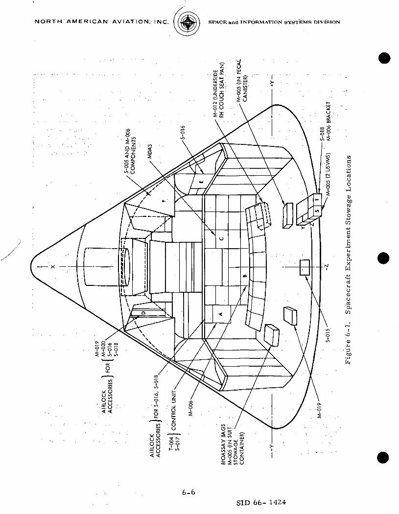
6 - 1 Spacecraft Experiment Stowage Locations . . . . 6 - 67-1 Building Block/Test Objective Matrix 7-497-2 Test Objective/Test Objective Matrix 7-51
TABLES
Table Page
6 - 1 Summary o f BB-17: Experiments . . . . . . 6 - 36 - 2 Experiment Equipment Stowage. . . . . . . 6 - 7
VI1
SID 66-1424

N O R T H A M E R I C A N A V I A T I O N , I N C . 4*a33'H SPACE and INFORMATION SYSTEMS DIVISION
1.0 INTRODUCTION
1. 1 SCOPE OF THE MMDB
In view of the similarity between the spacecraft to be used on the firstand second Block I manned missions, this report has been prepared for usein conjunction with the Mission Modular Data Book, First Block I .MannedMission, SID 66-1177, dated 1 September 1966 (hereafter referred to asSID 66-1177). The mission planning data presented in SID 66-1177 are givenin parametric form as functions of spacecraft weight, time, maneuveringrate, deadband width, etc., which are within the range of the existingspacecraft variations.
Of the seven sections in SID 66-1177, only three are changedin this volume:
Section 1.0 IntroductionSection 6.0 Building BlocksSection 7.0 Test Objectives
The remaining sections — i.e., 2.0 Spacecraft Constraints, 3.0 ElectricalPower, 4.0 Communications, and 5.0 Propellant Requirements—are directlyapplicable to this data book. The common-level concept and techniques formission synthesis, as described in SID 66-1177, remain the same.
1.2 BUILDING BLOCKS
Of the twenty-five building blocks presented in SID 66-1177, one blockhas been changed (BB-17: Experiments) and one block added (BB-19:Rendezvous and Simulated Docking). Although some of the scientific experi-ments are the same as those performed on the first Block I manned mission,they have been included in Building Block 1 7 of this volume to provide fullblock coverage for each spacecraft.
As discussed in the Introduction to SID 66-1177, the information pre-sented is applicable to earth-orbital manned missions at altitudes less than450 nautical miles. The building blocks are self-contained packages ofinformation for each function and/or spacecraft event. Since a rendezvousand simulated docking maneuver was not a test objective for the first mannedmission, Building Block 19 has been prepared to cover this event. It wouldbe identified as a category C operation in Table 1-1 of SID 66-1177.
1-1SID 66-1424

N O R T H A M E R I C A N A V I A T I O N . I N C . (f^^H| SPACE and INFORMATION SYSTEMS DIVISION
6.0 BUILDING BLOCKS
The two building blocks included in this volume represent the changesto Section 6.0 of SID 66-1177 that are unique to the second Block I mannedmission. All blocks presented in SID 66-1177 that are not specificallymentioned herein are assumed to require no changes and may be useddirectly for either mission.
6-1SID 66-1424

NORTH AMERICAN AVIATION, INC. SPACE and INFORMATION SYSTEMS DIVISION
BUILDING BLOCK 17: EXPERIMENTS
17.1 INTRODUCTION
This section contains information on the spacecraft in-flight experimentrequirements. The experiments are classified as medical (M), scientific (S),and technological (T) experiments. They are listed in the Summary(Table 6-1). Spacecraft stowage volumes are defined in Figure 6-1. Adetailed list of experiment equipment stowed in each volume is presentedin Table 6-2.
All experiments will be subject to the following rules:
1. Experiments shall not interfere with the crew's primaryactivities or responsibilities.
2. Experiments shall not be performed during emergency conditions.
17.2 SUMMARY
Table 6-1 summarizes this block.
Table 6-1. Summary of BB-17: Experiments
Experiments
Number
Old
M-4A
M-5A
M-6A
New
M-004
M-005
M-006
Title
In-flight Phono -cardiogram
Biomedical Assays,Body Fluids
Bone Demineral-ization
BlockPara.
17.3
17.4
17.5
Requirements for Experiment
Spacecraft Power
0.8 + 7 . 2 wattsfor MDAS
None
None
Attitude Hold
None
None
None
AstronautsParticipating
Commanderandnavigator
All
All
Remarks
Data recorded onMDAS power
Experiment limitedby number of samplebags
No in-flight interface
6-3
SID 66-1424

NORTH AMERICAN AVIATION, INC. SPACE and INFORMATION SYSTEMS DIVISION
Table 6-1. Summary of BB-17: Experiments (Cont)
Experiments
Number
Old
M-7A
M-ll
M-12
M-19
M-20
M-23
S-5A
S-6A
S-14
S-15
New
M-007
M-011
M-012
M-019
M-020
M-023
S-005
S-006
T-004
S-015
Title
Calcium BalanceStudy
Cytogenetic BloodStudies
Exercise Ergometer
Metabolic RateMeasurement
Pulmonary Function
Lower Body Nega-tive Pressure
Synoptic TerrainPhotography
Synoptic WeatherPhotography
Orbital OtolithFunction
Zero-g SingleHuman Cell
BlockPara.
17.6
17.7
17.8
17.9
17. 10
17.11
17.12
17.13
17.14
17.15
Requirements for Experiment
Spacecraft Power
None
None
4 watts + 7 . 2watts for MDAS
.,
3. 5 watts +7.2 watts forMDAS
3. 5 watts +7. 2 watts forMDAS
None
None
None
20 watts con-tinuous + 49. 5peak duringexperimentreadout
7. 5 watts
Attitude Hold
None
None
None
None
None
None
SC-Z axisperpendic-ular to earth
SC-Z axisperpendic-ular to earth
None
None
AstronautsParticipating
All
All
All
Any oneastronaut
Any oneastronaut
Any oneastronaut
Any oneastronaut
Any oneastronaut
Any oneastronaut
Oneastronaut
Remarks
M-5A equipmentplus fecal canister
No in-flightinterface
No AV's permittedduring experiment.M-012 performed inconjunction withM-019 and M-020
Utilizes MDAS.Performed in con-junction with M- 012and M-020
Utilize M-019 gasmeter and MDAS
No in-flightinterface
201bof RCS fuelallotted
201bof RCS fuelallotted
Shares data handlingsys and display con-trols with S-017
6-4
SID 66-1424
NORTH AMERICAN AVIATION. INC. SPACE and INFORMATION SYSTEMS DIVISION
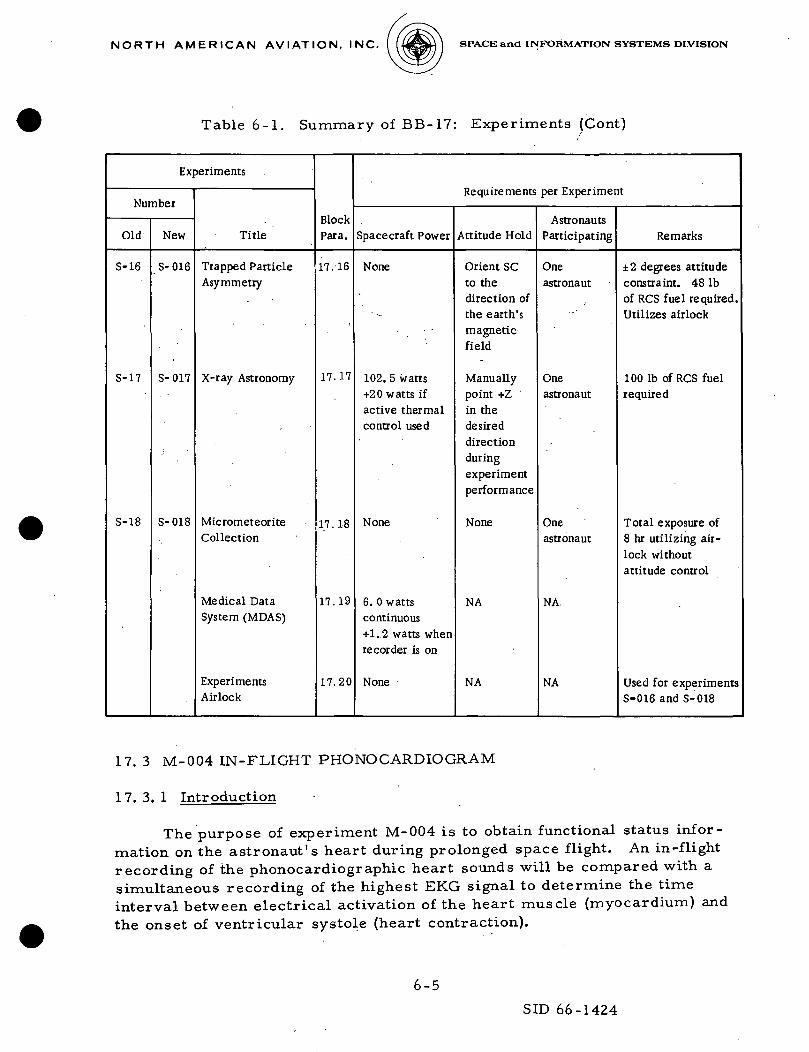
Table 6-1. Summary of BB-17: Experiments (Cont)
Experiments
Number
Old
S-16
S-17
S-18
New
S-016
S-017
S-018
Title
Trapped ParticleAsymmetry
X-ray Astronomy
MicrometeoriteCollection
Medical DataSystem (MDAS)
ExperimentsAirlock
BlockPara.
11.16
17.17
17.18
17.19
17.20
Requirements per Experiment
Spacecraft Power
None
102. 5 watts+20 watts ifactive thermalcontrol used
None
6. 0 wattscontinuous+1..2 watts whenrecorder is on
None
Attitude Hold
Orient SCto thedirection ofthe earth'smagneticfield
Manuallypoint +Zin thedesireddirectionduringexperimentperformance
None
NA
NA
AstronautsParticipating
Oneastronaut
Oneastronaut
Oneastronaut
NA.
NA
Remarks
±2 degrees attitudeconstraint. 48 Ibof RCS fuel required.Utilizes airlock
100 Ib of RCS fuelrequired
Total exposure of8 hr utilizing air-lock withoutattitude control
Used for experimentsS-016 and S-018
17. 3 M-004 IN-FLIGHT PHONO CARDIOGRAM
17. 3. 1 Introduction
The purpose of experiment M-004 is to obtain functional status infor-mation on the astronaut's heart during prolonged space flight. An in-flightrecording of the phonocardiographic heart sounds will be compared with asimultaneous recording of the highest EKG signal to determine the timeinterval between electrical activation of the heart muscle (myocardium) and
the onset of ventricular systole (heart contraction).
6-5
SID 66-1424
N O RT H AM E R 1C A N AV I ATI O N, I NC. SPACE and INFORMATION SYSTEMS DIVISION
COCO
• iH4->
rtiuO
0).donj
O
f-i0)ftXW
nifnU<DU.rtja
en
-JD
• 3bO
S S
6-6SID 66- 1424

NORTH AMERICAN AVIATION, INC. SPACE and INFORMATION SYSTEMS DIVISION
Table 6-2. Experiment Equipment Stowage
Equipment
Stowage Volume
D F- Utilization
Controls and displays panelStandpipeExtension rodHandle rodAblator door rod70-mm film packsMDASInterconnecting hose (3/4 OD x 24. 11)Nose clipMouthpieceBreathing valveAirlock handlePulmonary gas bag assemblyProtractorActive unitCalibration unit70-mm camera and ring sight70-mm film packSpot meterExposure dial250-mm lensUSVMS unitReceiversFilter (USVMS valve assembly)S-018 experimentCamera bracketOctopus cable
T-004 and S-017(Airlock) S-016 and S-018(Airlock) S-016 and S-018(Airlock) S-016 and S-018(Airlock) S-016 and S-018S-005 and operational
MDASM-019 and M-020M-019 and M-020M-019 and M-020M-019 and M-020(Airlock) S-016 and S-018M-020
S-016S-016S-005 and operationalS-005 and operationalS-005 and operationalS-005 and operationalS-005 and operationalM-005M-005M-005S-018S-006S-005
Additional experiment stowage locations:
Suit storage container (under LH couch)2 M-005 bags (V16-750098-41 and -51 assemblies)112 M-005 sample bags (total -41 and -51)21 plastic bags (under main lid -4i and -51) M-0052 cuff bags2 mixing bags (M-005)
M-012 Ergometer (under RH couch seat pan)S-015 Experiment (1) (aft of center couch on aft bulkhead)M-019 Experiment (1) (aft bulkhead aft of LH couch)1 USVMS unit (M-005) in fecal canister
6-7
SID 66-1424

NORTH A M E R I C A N AVIATION, INC. SPACE and INFORMATION SYSTEMS DIVISION
17. 3. 2 General Information
Performance of the experiment is dependent upon the prior connectionof the octopus cable to the medical'data acquisition system (MDAS) and tothe power source. The biomedical instrumentation interfaces with the MDASby means of a "T" adapter installed at the cobra cable/spacecraft electricalinterface of each crew position. There will be three T adapters. The octopuscable is connected to the T adapter of the crewman to be recorded, and thetelemetry input biomedical switch is set to either crewman. Test subjectswill be the commander and navigator.
17. 3. 3 Operational Timeline Segment
T im.e(min:sec)
t0 + 00:00
t0 + 00:50
t0 + 01:00
t0 + 16:00
t0 + 16:10
t0 + 17:00
t0 + 17:10
tn + 32:10
t0 + 32:20
Function
Connect octopus cable to T adapterof crewman to be recordedPerform required electricalswitching for recording of data
Record data
Biomedical tape recorder selectorswitch to OFF
Transfer cable to T adapter ofnext subject
Perform required electricalswitching for recording of data
Record data
Biomedical tape recorder selectorswitch to OFF
Cycle complete
Minimum total time = 32:20
A Time(min:sec)
00:50
00:10
15:00
00:10
00:50
00:10
15:00
00:10
6-8
SID 66-1424

NORTH AMERICAN AVIATION, INC. SPACE and INFORMATION SYSTEMS DIVISION
1 7. 3. 4 Power Requirement
The electrical power profile is depicted as follows. M-004 requires0. 8 watts continuously while operating. The MDAS requires 6. 0 wattscontinuously plus 1.2 watts for the recorder.
E1K
1<1
cr
8.0 WATTS.
*r >s.
0.8 WATTS
1 1) 5 10
U O.S
15 20 25 30MINUTES
i WATTS
135
140
17.4 M-005 BIOMEDICAL ASSAYS, BODY FLUIDS
1 7. 4. 1 Introduction
The purpose of experiment M-005 is to identify body changes thatoccur within the astronauts during weightlessness. This is accomplishedby a careful postflight analysis of body fluids collected during flight. Uri-nalysis will yield medical information on such biochemical constituentsas body steroids, catecholamines, enzymes, and salts. This experimentutilizes a radioactive aqueous solution for the urine volume/sample correl-ation. The radioactive course is tritium in nondangerous quantities.
17.4.2 General Information
Two crewmen will participate in the experiment, and each will have hisown personal urine sampling and volume measuring system (USVMS) unit.All urine eliminations are collected by means of the urine sampling devices,and a tritium tracer is introduced. A 75 cc sample of each micturition istaken, and the remainder is dumped overboard. The tritium radioactivitycannot penetrate its containers, either in the accumulator on the US VMS orin the sample bags. The potential experimental limitations are the quantityof sample bags (112), the supply of tritium in the USVMS, and the availableentry stowage volume. After completion of the experiment, the crew willuse the operational WMS for voiding.
6-9
SID 66-1424

NORTH A M E R I C A N AVIATION, INC. SPACE and INFORMATION SYSTEMS DIVISION
17. 4. 3 Operational Timeline Segment
Time(minrsec)
t0 + 00:00
t0 + 01:15
t0 + 02:15
t0 -1- 03:00
t0 -1- 04:00
tj_ + 00:00
t2 + 00:00
t2 + 02:20
t2 + 03:20
t2 + 04:15
ts + 00:00
t3 + 01:30
Function
Place bio-assay bag in operationalstowage, LEB
Ingress to aft equipment bay from LEB
Obtain urine sampling devices fromstowage, aft bay
Ingress to LEB from aft equipment bay
Prepare urine sampling device for use
Obtain and stow urine sample, LEB
Secure urine sampling device, LEB
Ingress to aft equipment bay from LEB
Stow urine sampling device, aftequipment bay
Ingress to LEB from aft equipment bay
Place bio-assay bag in boost/entrystowage, aft equipment bay
Complete cycle
A Time(min:sec)
01:15
01:00
00:45
01:00
02:05
12:05
02:20
01:00
00:55
01:00
01:30
Minimum total time = 24:55
17.5 M-006 BONE DEMINERALIZATION
The purpose of experiment M-006 is to determine the effect of weight-lessness and immobilization during space flight on the demineralization ofcertain bones within the body of each astronaut. (NOTE: No in-flightinterface)
6-10
SID 66-1424

N O R T H A M E R I C A N A V I A T I O N , I N C . 4^^>H ] SPACE and INFORMATION SYSTEMS DIVISION
17. 6 M-007 CALCIUM BALANCE STUDY
17. 6. 1 Introduction
The purpose of this experiment is to determine the rates of muscleand bone catabolism (nitrogen and calcium balance studies) on prolongedspace flights.
17.6.2 General Information
Astronauts will be maintained on a 0. 8 to 1. 0 gram calcium diet fortwo weeks prior to flight, during flight, and for two weeks postflight. Carefulrecording of intake and output will be required, and 100 cc aliquots of timedurine specimens will be analyzed. Dietary intake will be carefully analyzedfor calcium content, and a careful dietary record must be maintained. Amild laxative will be required postflight. Two 5-cc blood samples will berequired before and after flight with approximately a week between eachsample. Urine will be analyzed for phosphorus, nitrogen, other minerals,and hydroxproline. Nitrogen balance determinations will be made. Totalfecal specimens shall be stored.
17. 6. 3 Operational Timeline Segment
To be added at a later date.
1 7. 6. 4 Power Requirement
None
1 7. 6. 5 RCS Propellant Requirement
None
17.7 M-011 CYTOGENETIC BLOOD STUDIES
The purpose of experiment M-011 is to conduct preflight and postflightanalyses to determine if space environment produces cellular changes in theblood of the astronauts. These changes may not be apparent from routinemonitoring procedures. (NOTE: No in-flight interface)
17.8 M-012 EXERCISE ERGOMETER
17. 8. 1 Introduction
The purpose of experiment M-012 is to determined the benefits ofexercise during space flight.
6-11
SID 66-1424

NORTH AMERICAN AVIATION, INC. SPACE and INFORMATION SYSTEMS DIVISION
17. 8. 2 General Information
This experiment will be performed by each of the three crewmen, onetime on the fourth, eighth, and twelfth day of the mission. Additional exerciserequirements will be satisfied by using a bungee.
17. 8. 3 Operational Timeline Segment
Time(minrsec) Function
A Time(minisec)'
t0 + 00:00
tj + 00:00
tl + 01:30
02:11
+ 06:52
+ 21:52
+ 24:54
+ 26:25
t2 + 00:00
05:31
Unstow ergometer and prepare for use
Obtain couch pads and position forexercise
Remove clinical monitoring equipmentfrom stowage
Activate biomedical tape recorder andmonitor blood pressure, oral temper-ature and biomedical functions
Exercise
Monitor blood pressure, oral temper-ature, and biomedical functions
Deactivate recorder and stow clinicalequipment
Remove pads from exercise positionand install on center couch
Stow ergometer
Complete cycle
03:10
01:30
00:41
04:41
15:00
03:02
01:31
01:15
05:31
Minimum total time = 3 6 : 2 1
17.8.4 Power Requirement
The electrical power profile for M-012 is presented as follows. TheM-012 requires 4 watts for operation. The MDAS requires 6. 0 wattscontinuously plus 1. 2 watts for 3 recorders.
6-12
SID 66-1424

N O R T H A M E R I C A N A V I A T I O N , I N C . (tf*|>H) SPACE and INFORMATION SYSTEMS DIVISION
J 1.2 WATTS
ICXLLU
B0.
<
S
\ I I) 5 10 15
MINUTES
4 WATTS
1 1 120 25
|30
17.9 M-019 METABOLIC RATE MEASUREMENT
17. 9. 1 Introduction
The purpose of the experiment is to measure the metabolic rates ofthe astronauts during space flight. This measurement will provide dataconcerning the activity level of the astronauts in the gravity-free environ-ment of the CSM. Information will be provided which is essential for theestablishment of physiological requirements in the areas of respiration,nutrition, and thermal balance.
1 7. 9. 2 General Information
An established method for the determination of metabolic rate is thatof indirect calorimetry in which oxygen consumption is determined from themeasurement of respired gases. This method is appropriate for spacecraftuse. An astronaut is required to assemble equipment and perform theexperiment two or three times per 24-hour period. The astronaut removesthe gas meter from the stowed position and places the instrument on thefood shelf. He removes from Volume D a nose clip, mouthpiece, breathingvalve, and connecting tubing and cables. After assembling this equipment,he breathes into the gas meter during periods of rest and at varying activitylevels. Experiment duration will be 10 to 20 minutes.
17. 9. 3 Operational Timeline Segment
To be added when available.
17.9.4 Power Requirement
The M-019 gas meter requires 3. 5 watts continuously while operating,plus 7. 2 watts required for the MDAS and recorders.
6-13
SID 66-1424

N O R T H A M E R I C A N A V I A T I O N , I NC. 4*aS»H SPACE and INFORMATION SYSTEMS DIVISION
17. 10 M-020 PULMONARY FUNCTION
17.10.1 Introduction
The purpose of experiment M-20 is to investigate and measure thechanges in vital capacity, residual volume, and maximum breathing capacityof astronauts functioning in a space environment.
17. 10. 2 General Information
Vital capacity, tidal volume, and expiratory reserve volume aredetermined by standard exhalation spirometric maneuvers. A nose clip,mouthpieces, a breathing valve and dry gas meter (M-019) type spirometerare used. Respiratory rates are obtained from the operational safetymonitoring impedance pneumograph and are used along with the total volumeexpired (as measured by the gas meter) to obtain an average tidal volumeover a timed interval. A crew member connects the 80-liter lightweightplastic film bag to the gas meter, and all the gas within the bag is evacuatedthrough the meter for volume measurements. Expired volumes for maximumvoluntary ventilation are collected over a 15-second period of maximum ,;
effort. The collection will be for a 30-second timed period. The exerciserate will be 3000 ft-lb/minute for 15 minutes. Expired volumes or restingminute volumes will be collected through a 15-minute pre-exercise restingperiod.
17. 10. 3 Operational Timeline Segment
To be added when available.
17. 10.4 Power Requirement
This utilizes the M-019 gas meter which requires 3. 5 watts continuouslywhile operating plus 7. 2 watts required for the MDAS and recorder.
17. 11 M-023 LOWER BODY NEGATIVE PRESSURE
17. 11. 1 Introduction
The purpose of this experiment is to assess any progressive decrementin integrity of the cardiovascular system following prolonged space flight.
17.11.2 General Information
This experiment will be pre- and postflight tests only. There are nospacecraft requirements. The mission requirements are:
6-14
SID 66-1424
N O R T H A M E R I C A N A V I A T I O N , INC. U^SaM I SPACE and INFORMATION SYSTEMS DIVISION
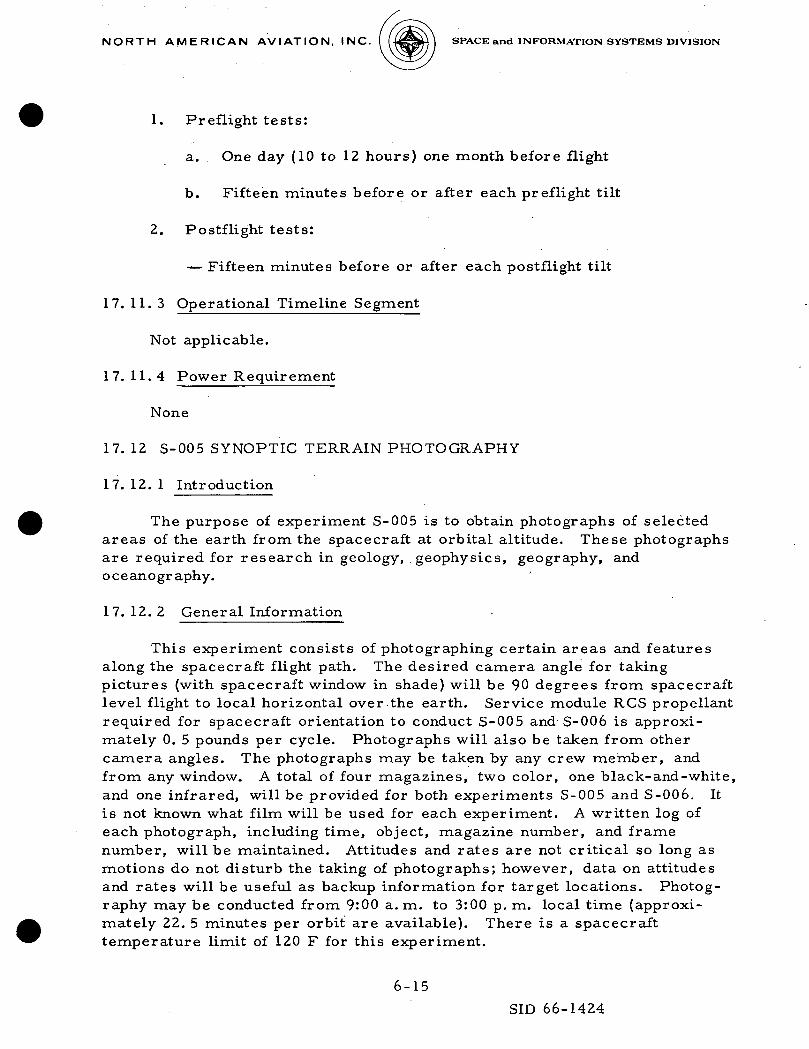
1. Preflight tests:
a. One day (10 to 12 hours) one month before flight
b. Fifteen minutes before or after each preflight tilt
2. Postflight tests:
— Fifteen minutes before or after each postflight tilt
17. 11. 3 Operational Timeline Segment
Not applicable.
17. 11.4 Power Requirement
None
17. 12 S-005 SYNOPTIC TERRAIN PHOTOGRAPHY
17. 12. 1 Introduction
The purpose of experiment S-005 is to obtain photographs of selectedareas of the earth from the spacecraft at orbital altitude. These photographsare required for research in geology, .geophysics, geography, andoceanography.
17. 12. 2 General Information
This experiment consists of photographing certain areas and featuresalong the spacecraft flight path. The desired camera angle for takingpictures (with spacecraft window in shade) will be 90 degrees from spacecraftlevel flight to local horizontal over the earth. Service module RCS propellantrequired for spacecraft orientation to conduct S-005 and S-006 is approxi-mately 0. 5 pounds per cycle. Photographs will also be taken from othercamera angles. The photographs may be taken by any crew member, andfrom any window. A total of four magazines, two color, one black-and-white,and one infrared, will be provided for both experiments S-005 and S-006. Itis not known what film will be used for each experiment. A written log ofeach photograph, including time, object, magazine number, and framenumber, will be maintained. Attitudes and rates are not critical so long asmotions do not disturb the taking of photographs; however, data on attitudesand rates will be useful as backup information for target locations. Photog-raphy may be conducted from 9:00 a.m. to 3:00 p. m. local time (approxi-mately 22. 5 minutes per orbit are available). There is a spacecrafttemperature limit of 120 F for this experiment.
6-15
SID 66-1424
NORTH A M E R I C A N AVIATION, INC. SPACE and INFORMATION SYSTEMS DIVISION
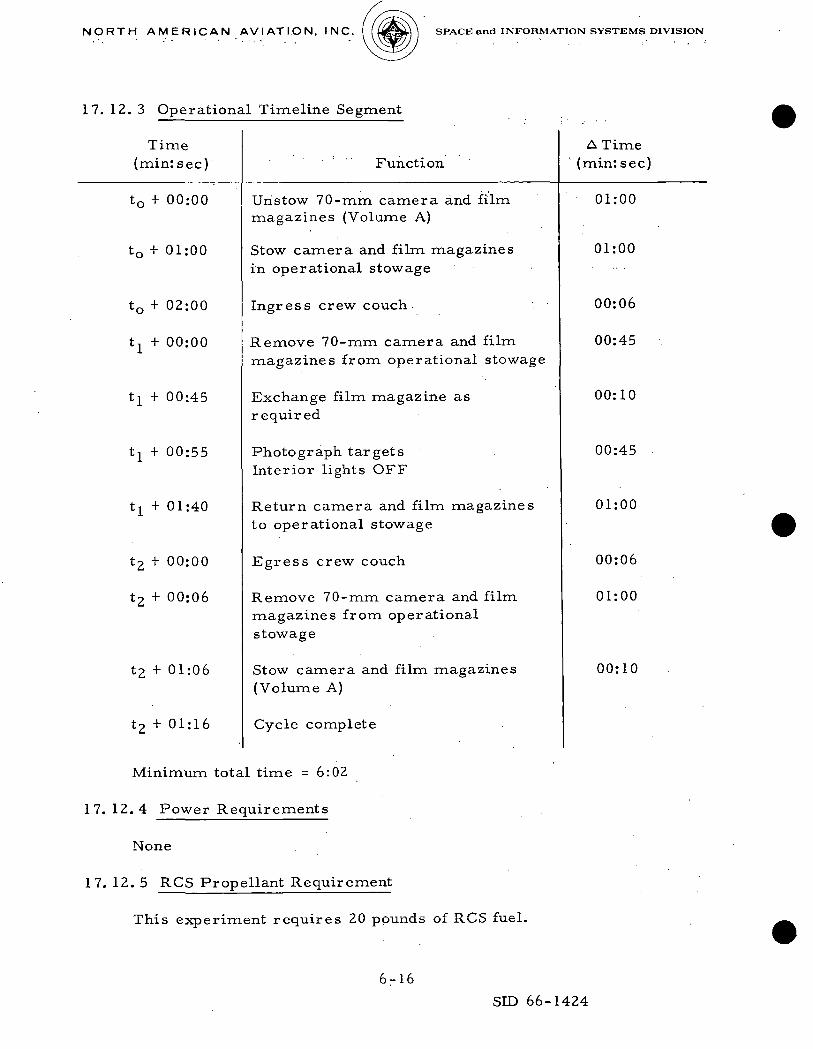
17. 12. 3 Operational Timeline Segment
Time(minrsec) Function
A Time(min: sec)
t0 + 00:00
t0 + 01:00
t0 + 02:00
t1 + 00:00
t]_ + 00:45
tl + 00:55
tl + 01:40
t2 + 00:00
t2 f 00:06
t2 + 01:06
t2 + 01:16
Unstow 70-mm camera and filmmagazines (Volume A)
Stow camera and film magazinesin operational stowage
Ingress crew couch
Remove 70-mm camera and filmmagazines from operational stowage
Exchange film magazine asrequired
Photograph targetsInterior lights OFF
Return camera and film magazinesto operational stowage
Egress crew couch
Remove 70-mm camera and filmmagazines from operationalstowage
Stow camera and film magazines(Volume A)
Cycle complete
Minimum total time = 6:02
17. 12.4 Power Requirements
None
17.12.5 RCS Propellant Requirement
This experiment requires 20 pounds of RCS fuel.
01:00
01:00
00:06
00:45
00:10
00:45
01:00
00:06
01:00
00:10
6-16SID 66-1424

N O R T H A M E R I C A N A V I A T I O N , I N C . -MS^tH ] SPACE and INFORMATION SYSTEMS DIVISION
17. 13 S-006 SYNOPTIC WEATHER PHOTOGRAPHY
17. 13. 1 Introduction
The purpose of experiment S-006 is to obtain selective, high-qualityphotographs of cloud patterns taken from the spacecraft at orbital altitude.These photographs will be used for studies of weather system structuresaround the earth.
17. 13. 2 General Information
Same as 17. 8. 2.
17. 13. 3 Operational Timeline Segment
Same as 17. 8. 3. ;
17. 13.4 Power Requirement
None
17. 13. 5 RCS Propellant Requirement
This experiment requires 20 pounds of RCS fuel.
17. 14 T-004 ORBITAL OTQLITH FUNCTION
17. 14. 1 Introduction
The purpose of experiment T-004 is to record directly the changesin activity of the otolith system which might take place in orbital flight(using bullfrogs as subjects).
17. 14. 2 General Information
The orbital otolith experiment is designed to record the bioelectricaction potentials in the bullfrog during weightlessness and repeated accel-erations (obtained by spinning the animals with a small rotator) and todetermine the adaptability of the otolith system to •weightlessness and accel-eration during extended periods of flight. The experiment equipment willhave continuous power supplied to it after installation into the spacecraftjust before launch. This power will be provided initially by a ground powersource. At approximately T-3 hours an astronaut positions the main Anonessential bus to ON and pushes the T-004 experiment circuit breaker in.
6-17
SID 66-1424

NORTH AMERICAN AVIATION, INC. SPACE and INFORMATION SYSTEMS DIVISION
This switches power from the ground source to spacecraft power. "Whilethe spacecraft is in flight, the stimulus to the otolith system is applied byastronaut-activated rotation (0 .5 g) of the specimen capsule.
17. 14.3 Operational Timeline Segment
Time(min:sec)
t0 + 00:00
t0 + 00:15
t0 + 00:20
ti + 00:00
ti + 00:15
t! + 00:20
ti + 00:25
ti + 01:12
t! +.01:32
t! + 01:37
ti + 01:57
ti + 01:59
ti + 02:04
t!.+ 03:04
Function
Activate experiment T-004/S-017 mainpower
Open scientific compartment A
Set T-004 main power switch to ON
Close scientific compartment A
Perform experiment T-004 test cycle .
Open scientific compartment A
Depress FROG PWR ON button onportable control unit
Depress RCDR READ IN button onportable control unit
Record mission time and frog cycle num-ber on recorder
Ver i fy f rog cycle number in experiments log
Depress VOICE button on portable controlunit
Announce mission elapsed time and frogcycle number
Release VOICE button on portable controlunit
Depress FROG CENT CYCLE button onportable control unit
Record frog cycle number and missionelapsed time in experiments log
Wait time: to complete experiment/record-ing cycle
Note: After completion of four experimentcycles, allow the data recorder to operate
ATime. (min: sec)
00:15
00:05
00:15
00:15
00:05
00:05
00:47
00:20
00:0.5
00:20
00:02
00:05
01:00
05:38
4 x 8:42 =34:48
6-11
SID 66-1424
NORTH AMERICAN AVIATION, INC.
Time(min:sec)
SPACE and INFORMATION SYSTEMS DIVISION
FunctionATime
(min: sec)
+ 34:48
+ 34:53
tz + 00:00
tz + 00:15
to + 00:20
tz + 00:25
t + 00:3.0
+ 00:35
+ 08:35
+ 08:40
t3 + 00:00
13 + 00:15
13 + 00:20
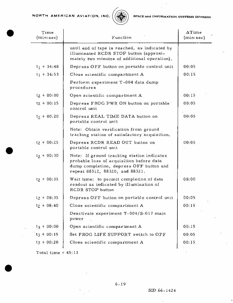
until end of tape is reached, as indicated byilluminated RCDR STOP button (approxi-mately two minutes of additional operation).
Depress OFF button on portable control unit
Close scientific compartment A
Perform experiment T-004 data dumpprocedures
Open scientific compartment A
Depress FROG PWR ON button on portablecontrol unit
Depress REAL TIME DATA button onportable control unit
Note: Obtain verif icat ion from groundtracking station of satisfactory acquisition.
Depress RCDR READ OUT button onportable control unit
Note: If ground tracking station indicatesprobable loss of acquisition before datadump completion, depress OFF button andrepeat 88312, 88320, and 88321.
Wait time: to permit completion of datareadout as indicated by illumination ofRCDR STOP button
Depress OFF button on portable control unit
Close scientific compartment A
Deactivate experiment T-004/S-017 mainpower
Open scientific compartment A
Set FROG LIFE SUPPORT switch to OFF
Close scientif ic compartment A
00:05
00:15
00:15
00:05
00:05
00:05
08:00
00:05
00:15
00:15
00:05
00:15
Total time = 45: 13
6-19
SID 66-1424

NORTH AMERICAN AVIATION, INC. SPACE and INFORMATION SYSTEMS DIVISION
17. 14.4 Power Requirement
The T-004 otolith experiment requires 20 watts continuous powerdissipation from the time the live specimens are inserted through completionof their operational cycle. The following profile includes this requirementin the total power dissipation analysis.
DAYS IN ORBIT
HOURS AFTER LAUNCH T
1 2
0 T+24
2 2 21111*1111111*1111* 1 1 1
3
T-t48 T +
2 S1 1 i * i M i ii
4 5
72 T-W6 T+
)•
6 7 I 8 <
20 T+H4 T+168 T-H92
1
?
T+216
T-004 READ-INS: 3-HOUR INTERVALS,4 MINUTES EACH
• T-004 READ-INS: ONE-HOUR INTERVALS,4 MINUTES EACH2 READ-OUTS PER DAY, 8 MINUTES EACH(3 READ-OUTS WORST CASE)
• RECORDER READ-OUTS REQUIRE 33 WATTSTOTAL POWER DISSIPATION.
•READ-INS REQUIRE 44.5 WATTS NORMAL;69.5 WATTS FOR 20-SECOND PEAK DURINGREAD-INS FOR TOTAL POWER DISSIPATION.
17. 15 S-015 ZERO-G SINGLE HUMAN CELL,
17. 15. 1 Introduction
The purpose of experiment S-015 is to study the influence of zerogravity on living human cells and tissue cultures. The experiment willtry to answer the question of whether or not the absence of gravity has asignificant e f fec t on isolated human cells. The investigation will consistof the recording of the morphologic and physiologic functions of the cellsand the bio-chemical status of the cells at zero gravity.
17. 15. 2 General Information
The experiment procedure is to record by phase contrast time-lapsemotion pictures the functional and morphological aspects of single livinghuman cells. These will include a study of pinocytosis, mitosis, cell size,
6-20
SID 66-1424
NORTH AMERICAN AVIATION, INC. SPACE and INFORMATION SYSTEMS DIVISION
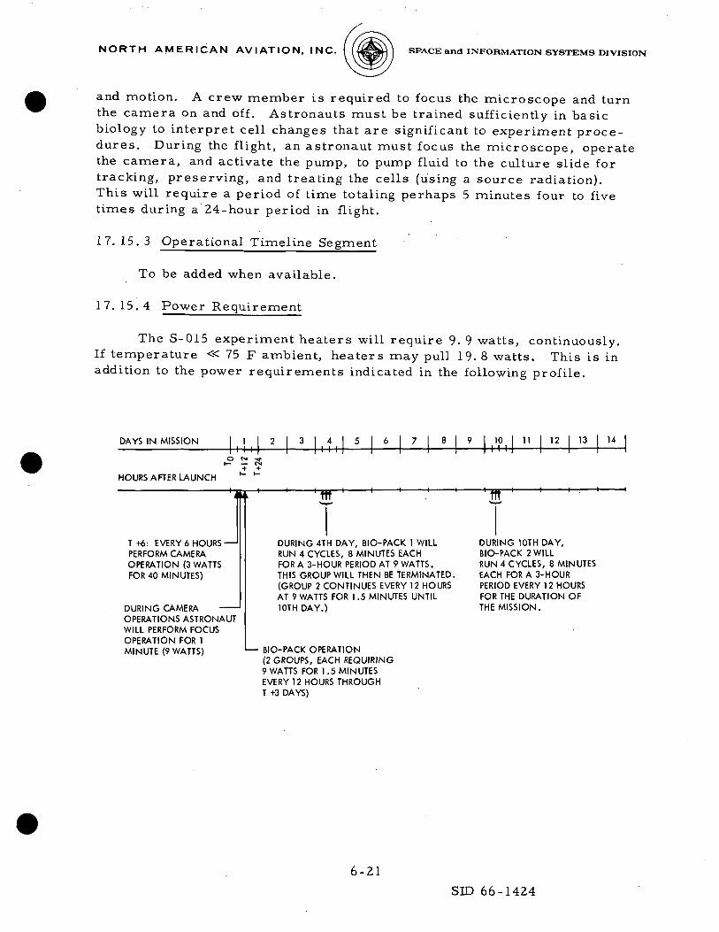
and motion. A crew member is required to focus the microscope and turnthe camera on and off . Astronauts must be trained sufficiently in basicbiology to interpret cell changes that are significant to experiment proce-dures. During the flight, an astronaut must focus the microscope, operatethe camera, and activate the pump, to pump fluid to the culture slide fortracking, preserving, and treating the cells (using a source radiation).This will require a period of time totaling perhaps 5 minutes four to fivetimes during a 24-hour period in flight.
17.15.3 Operational Timeline Segment
To be added when available.
17.15.4 Power Requirement
The S-015 experiment heaters will require 9.9 watts, continuously.If temperature « 75 F ambient, heaters may pull 19. 8 watts. This is inaddition to the power requirements indicated in the following profile.
DAYS IN MISSION, 1 ,
2 3 4M I
5 6 1 7 8 9 101 1 1
11 12 13 | 14
HOURS AFTER LAUNCH
T -hi: EVERY 6 HOURS—'PERFORM CAMERAOPERATION (3 WATTSFOR 40 MINUTES)
DURING CAMERAOPERATIONS ASTRONAUTWILL PERFORM FOCUSOPERATION FOR 1MINUTE (9 WATTS)
DURING 4TH DAY, BIO-PACK 1 WILLRUN 4 CYCLES, 8 MINUTES EACHFOR A 3-HOUR PERIOD AT 9 WATTS.THIS GROUP WILL THEN BE TERMINATED.(GROUP 2 CONTINUES EVERY 12 HOURSAT 9 WATTS FOR 1.5 MINUTES UNTIL10TH DAY.)
BIO-PACK OPERATION(2 GROUPS, EACH REQUIRING9 WATTS FOR 1.5 MINUTESEVERY 12 HOURS THROUGHT +3 DAYS)
DURING 10TH DAY,BIO-PACK 2 WILLRUN 4 CYCLES, 8 MINUTESEACH FOR A 3-HOURPERIOD EVERY 12 HOURSFOR THE DURATION OFTHE MISSION.
6-21
SID 66-1424
NORTH AMERICAN AVIATION, INC. SPACE and INFORMATION SYSTEMS DIVISION
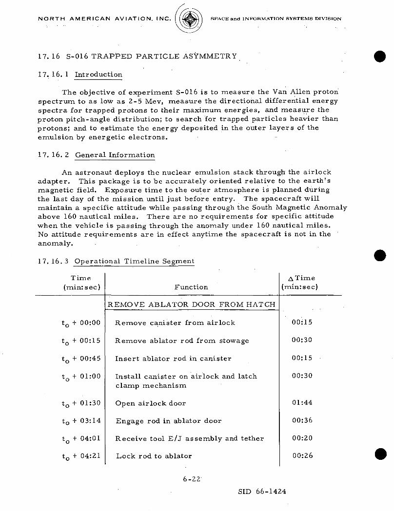
17. 16 S-016 TRAPPED PARTICLE ASYMMETRY
17. 16. 1 Introduction
The objective of experiment S-016 is to measure the Van Allen protonspectrum to as low as 2-5 Mev, measure the directional differential energyspectra for trapped protons to their maximum energies, and measure theproton pitch-angle distribution; to search for trapped particles heavier thanprotons; and to estimate the energy deposited in the outer layers of theemulsion by energetic electrons.
17. 16. 2 General Information
An astronaut deploys the nuclear emulsion stack through the airlockadapter. This package is to be accurately oriented relative to the earth'smagnetic field. Exposure time to the outer atmosphere is planned duringthe last day of the mission until just before entry. The spacecraft willmaintain a specific attitude •while passing through the South Magnetic Anomalyabove 160 nautical miles. There are no requirements for specific attitudewhen the vehicle is passing through the anomaly under 160 nautical miles.No attitude requirements are in effect anytime the spacecraft is not in theanomaly.
17. 16. 3 Operational Timeline Segment
Time(min: sec)
t0 + 00:00
t0 + 00:15
t0 + 00:45
t0 + 01:00
t0 + 01:30
t0 + 03:14
t0 + 04:01
t0 + 04:21
Function
REMOVE ABLATOR DOOR FROM HATCH
Remove canister from airlock
Remove ablator rod from stowage
Insert ablator rod in canister
Install canister on airlock and latchclamp mechanism
Open airlock door
Engage rod in ablator door
Receive tool E/J assembly and tether
Lock rod to ablator
ATime(min:sec)
00:15
00:30
00:15
00:30
01:44
00:36
00:20
00:26
6-22
SID 66-1424

NORTH AMERICAN AVIATION, INC. SPACE and INFORMATION SYSTEMS DIVISION
Time(min:sec)
t0 + 04:52
t0 -1- 05:35
t0 + 07:19
t0 + 08:25
ti + 00:00
ti + 00:20
ti +00:41
ti + 01:22
ti + 01:37
tj + 04:44
ti + 05:15
ti + 06:00
ti + 07:00
tz + 00:00
t2 + 01:44
t2 + 02:10
Function
Pull ablator door into canister
Close airlock door
Remove canister with ablator door fromairlock
Stow ablator door with rod on main hatchand stow canister temporarily
PREPARE S-016 UNIT FOR DEPLOYMENT
Attach E/J lanyard to wrist
Obtain collar from Volume D
Obtain standpipe from Volume A
Remove canister from temporarystowage
Assemble standpipe and collar tocanister
Assemble deployment rod assembly andinsert into standpipe
Obtain experiment S-016 unit
Attach S-016 unit to deployment rod
Install canister with S-016 unit onairlock and latch clamp mechanism
DEPLOY EXPERIMENT S-016 NUCLEAREMULSION DETECTOR UNIT
Open airlock
Deploy experiment S-016
Withdraw experiment S-016 unitinto canister
A Time(min:sec)
00:43
01:49
01:06
00:20
00:20
00:21
00:26
00:15
00:20
00:30
00:20
01:00
01:05
01:44
00:26
00:50
6-23SID 66-1424

NORTH A M E R I C A N AV I ATI O N, I NC. SPACE and INFORMATION SYSTEMS DIVISION
Time(minrsec)
t2 + 03:00
ts + 00:00
t3 + 00:55
t3 + 01:31
t3 + 02:17
ts + 03:17
t3 + 03:58
ts + 06:24
ts + 06:44
ts + 07:05
t3 + 08:15
ts + 08:45
t3 + 10:29
t3 + 11:18
ts + 11:48
t3 + 12:19
t3 + 12:55
Function
Close airlock door
SECURE EXPERIMENT S-016
Remove canister with experimentfrom airlock
Remove experiment S-016 unit fromdeployment rod
Stow S-016 unit
Remove canister and standpipe fromdeployment rod assembly
Stow protractor and handle
Disassemble deployment rods
Receive canister with standpipe andcollar
Remove ablator door from stowageon hatch
Insert ablator rod with ablator doorin canister .
Install canister on airlock and latchclamp mechanism
Open airlock door
Install ablator door
Receive tool E/J assembly andtether
Unlock rod from ablator door
Withdraw rod from ablator door
Detach and pass tool E/J
A Time .(min:sec)
01:09
00:55
00:36
00:46
01:00
00:41
02:26
00:20
00:21
01:10
00:30
01:44
00:49
00:30
00:31
00:36
00:21
6-24.
SID 66-1424

NORTH AMERICAN AVIATION, INC. SPACE and INFORMATION SYSTEMS DIVISION
Time(min:sec)
t3 + 13:16
t3 .+ 15:00
t3 + 15:31
t3 + 15:41
t3 + 15:46
t3 + 16:01
Function
Close airlock door
Remove canister from airlock
Remove ablator rod from canister
Receive ablator door rod
Install plug in canister and stowablator door in Volume A
Install canister on airlock and latchclamp mechanism
A Time(min:sec)
01:44
00:31
00:10
00:05
00:15
00:10
Minimum time = 37:10
17. 16.4 Power Requirement
None
17.16.5 RCS Propellant Requirement
This experiment requires 48 pounds of RCS fuel.
17.17 S-01 7 X-RAY ASTRONOMY
17. 17. 1 Introduction
The purpose of experiment S-017 is to study X-ray sources outside thesolar system. These sources cannot be studied from the earth due to absorp-tion of the X-rays into the atmosphere. The scientific objectives of theproposed experiment are:
1. To determine the positions of the known X-ray sources toa few arc minutes
2. To measure the X-ray spectrum from the stronger sources
3. To observe certain objects of astronomical interest for evidenceof X-ray emission. These objects would include, strong radioemission centers, the galactic center, the ecliptic and certainextragalactic objects such as supernova remnants.
6-25
SID 66-1424

NORTH A M E R I C A N AVIATION, INC. SPACE and INFORMATION SYSTEMS DIVISION
4. To scan the galactic equator for X-ray sources
5. To measure the relative and absolute strengths of the X-rayemission from the sources
17. 17. 2 General Information
An astronaut performs an in-flight calibration of the position or boresighting of the X-ray axis. This is done by pointing the star sensor axis ata known star and adjusting the vehicle attitude so that the sensor axis pointsexactly at the star for an instant. Pressing the MARK button records theG&N (IMU) coordinates at this instant. After this axis calibration, the space-craft is slewed to observe a known X-ray source or to scan for source. Thevisual display unit within the command module permits the crew to orient thespacecraft and assists in maintaining the X-ray source in the field of view.
17. 17. 3 Operational Timeline Segment
To be supplied when available.
17. 17.4 Power Requirement .
The S-017 experiment requires a total power dissipation of 102. 5 wattsnominal plus 20 watts if active thermal control is required. The followingtime-oriented operational profile presents the power dissipation.
DAYS IN ORBIT
HOURS AFTER LAUNCH T0 T+24 T-^8 T+72 T+96 T+]20 T+144 T+168 T+i92 T+216
•4- I I I
T +25: S-017OPERATIONAL CHECK(15 MINUTES)
T +74: S-017 BORESIGHT-AND THERMALDEFORMATION TEST,PART I (32 MINUTES)
• READ-INS REQUIRE 102.5WATTS NORMAL,PLUS 20 WATTS IF ACTIVE THERMALCONTROL IS REQUIRED.
• RECORDER READ-OUTS REQUIRE 33 WATTS.
• OPERATIONAL CHECK REQUIRES.(TBD).
• BORE-SIGHT AND THERMAL DEFORMATIONTEST (PARTI) REQUIRES (TBD).
• THERMAL DEFORMATION TEST(PART II) REQUIRES (TBD).
222222922222222828tmmmmt.mt
TIME FOR ADDITIONALMEASUREMENTS ASREQUESTED BY SCIENTIFICOPERATIONAL SUPPORTPERSONNEL AND APPROVEDBY MISSION CONTROL
L- 18 READ-INS, 30 MINUTESEACH; AND 18 READ-OUTS,8 MINUTES EACH
T +78: S-017 THERMALDEFORMATION TEST,PART II (30 MINUTES)
6-26
SID 66-1424

N O R T H A M E R I C A N A V I A T I O N , I N C . 4^SH I SPACE and INFORMATION SYSTEMS DIVISION
17.17.5 RCS Propellant Requirement
This experiment requires 100 pounds of RCS fuel.
17. 18 S-018 MICROMETEORITE COLLECTION
17. 18. 1 Introduction
The purpose of experiment S-018 is to collect small micrometeoritesand to measure directly the fluxes of larger micrometeorite particles atsatellite altitudes. The secondary purpose is to carry out biological exposureand collection experiments.
17. 18. 2 General Information
The micrometeorite collection experiment equipment will be stowed inthe command module during launch and much of the flight. An astronautplaces the collector container in the airlock canister and deploys it by meansof an extension rod through the airlock. An in-flight exposure of eight hoursis required. This exposure may be continuous or may be conducted duringportions of several orbits. There is no requirement for attitude control. TheRCS jets will be OFF to prevent collection plate contamination.
17. 18. 3 Operational Timeline Segment
To be added when available
17.18.4 Power Requirement
None
17.19 MEDICAL DATA ACQUISITION SYSTEM
17.19.1 Introduction
The MDAS is used to record the phonocardiogram (M-004) and bio-medical data as well as supporting experiments M-012, M-019, M-020,M-005, and M-007. The biomedical data are used to evaluate experimentM-004. Additionally, timing signals are provided to the onboard voicerecorder. The MDAS is installed in Volume C and receives signals andpower through the octopus cable. The power is obtained at a connector inVolume A. The tape recorder provides a seven-channel tape record ofphysiological signals related to the medical experiments. The followingdata are to be recorded:
6-27
SID 66-1424

NORTH A M E R I C A N AVIATION, INC. SPACE and INFORMATION SYSTEMS DIVISION
1. Impedance pneumograph
2. Electrocardiogram (EKG)
3. Phonocardiogram (PCG)
4. Ergometer work output signal
5. Oral temperature/blood pressure pump
6. Systolic and diastolic markers
7. Time code
17. 19. 2 General Information
The MDAS recording requirements for this mission are as follows:
Channel Requirement
4
6
Impedance pneumograph—2 men 20 minuteseach per day
Ergometer — 3 men 40 minutes each on4th, 8th, and 12th days
EGG 1—2: men 20 minutes each per day
EGG 2/phonocardiagram—2 men20 minutes each per day
Timing
17. 19. 3 Operational Timeline Segment
Time(minrsec)
t0 + 00:00
t0 + 00:15
t0 + 00:25
Function
Unstow octopus cable (Area D)
Connect octopus cable to biomedicaltape recorder
Verify main power switch OFF
A Time(min:sec)
00:15
00:10
00:02
6-28SID 66-1424

NORTH AMERICAN AVIATION, INC. SPACE and INFORMATION SYSTEMS DIVISION
Time(mincsec) Function
A Time(min:sec)
t0 + 00:27
tn + 02:27
t0 + 02:37
t0 + 02:47
+ 00:00
+ 02:00
tj + 02:15
Route octopus cable and attach toVelcro tabs
Connect octopus cable to electricpower (Area A)
Connect octopus cable to any crew-man's T adapter
Prepare biomedical tape recorder forservice
Disconnect octopus cable fromcrewman's T adapter, electricalpower, and biomedical tape recorderPrepare cable for stowage
Stow octopus cable (Area D)
Cycle complete
02:00
00:10
00:10
01:05
02:00
00:15
Minimum total time = 6:07
17. 19. 4 Power Requirement
The MDAS requires 6. 0 watts continuously while operating plus1. 2 watts for the biomedical tape recorder plus any additional experimentpower requirement.
17.20 EXPERIMENTS AIRLOCK
The airlock experiments canister is utilized for experiments S-016,Trapped Particle Asymmetry, and S-018, Micrometeorite Collection. Theairlock consists of an inner hatch pressure door and outer hatch door; innerrecessed airlock adapter block; experiment canisters and deployment rods,mechanism, etc. The operation of the airlock system during use for oneexperiment in flight consists of
1. The inner hatch pressure door is transposed from its closedposition to an adjacent open position on the inside surface of theinner structure by means of a hand cranked mechanism.
6-29SID 66-1424

N O R T H A M E R I C A N A V I AT I O N , I N C . 4«a»H ] SPACE and INFORMATION SYSTEMS DIVISION
2. The outer hatch door is withdrawn inward by means of anotherconnector latch rod mechanism so that it clears the inner hatchand then is stored in the inner recessed airlock adapter block.
3. The inner hatch pressure door is reseated to seal the commandmodule.
4. The inner recessed airlock adapter block is removed and storedin spacecraft.
5. The first experiment contained within the canister is clamped andattached to opening flange.
6. The inner hatch pressure door is reopened.
7. The experimental package is deployed beyond the outer mold lineby means of a deployment rod .
8. When experiment period is complete, the experiment packageis returned within canister.
9.., The inner hatch door is closed. ;
10. The canister with the experiment is removed and stowed.
11. The adapter block which contains the outer hatch door is replaced.
12. The inner hatch door is opened.
13. The outer hatch door is extended into closed position and thedeployment rod removed.
14. The inner hatch door is closed.
To run the second experiment, the operation would consist of startingwith steps 10 and 11. The first experiment is unloaded and the secondexperiment fitted in the same canister. The sealing surfaces of the flangeare checked, and then steps 4 to 14 are repeated.
6-30SID 66-1424

N O R T H A M E R I C A N A V I A T I O N , I N C . i^W SPACE and INFORMATION SYSTEMS DIVISION
BUILDING BLOCK 19: RENDEZVOUS ANDSIMULATED DOCKING
19.1 INTRODUCTION
The second Block I manned mission includes a rendezvous and simu-lated docking maneuver which consists of providing a relative AV at CSM/S-IVB separation, so that the CSM passes above and behind the S-IVB,moving away. As the vehicles orbit the earth, the CSM moves below theS-IVB, its velocity increases, and the relative distance between the vehiclesdecreases. A terminal phase initiation (TPI) maneuver, followed by abraking maneuver, brings the vehicles to a station-keeping configuration,after which the CSM closes on the S-IVB and simulates a docking maneuver.
Building Block 19 (BB-19) differs from the building blocks presented inSID 66-1177 in that a timeline cannot be prepared without knowledge ofspecific trajectory data. In place of a timeline, a sequence of events isgiven in Paragraph 19.2.2. In preparing the sequence of events, an attemptwas made to utilize those blocks that exist in SID 66-1177. For the phasesof Building Block 19 for which this was not possible, recommended pro-cedures are described.
The initial point of reference selected for the sequence of events is theCSM/S-IVB separation (BB-6). This selection provides a convenient refer-ence point and permits a slight alteration in BB-6 without completely rewritingthe block.
19.2 OPERATIONAL DATA
19.2.1 General Information
Various assumptions have been made in the preparation of BB-19.Among these assumptions are the following:
1. Prior to CSM/S-IVB separation, an IMU alignment has beenperformed (BB-7, Case I).
2. The optics have been unstowed and mounted.
3. It is desired to track the S-IVB by optical means following theCSM/S-IVB separation.
6-31
SID 66-1424
NORTH AMERICAN AVIATION, INC. SPACE and INFORMATION SYSTEMS DIVISION
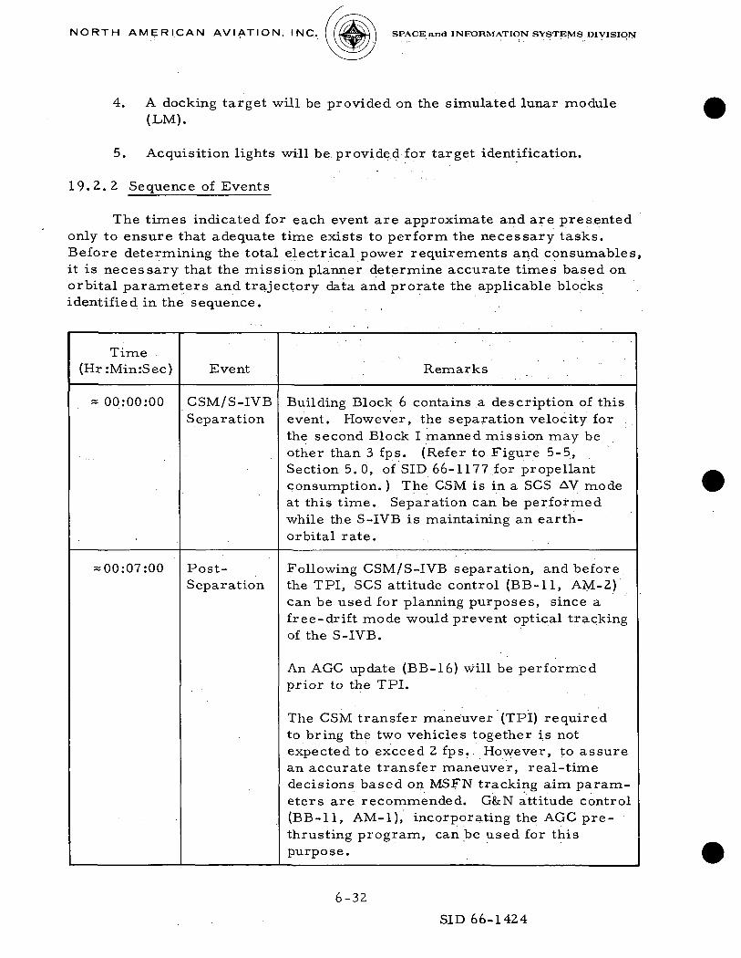
4. A docking target will be provided on the simulated lunar module(LM).
5. Acquisition lights will be provided for target identification.
19.2.2 Sequence of Events
The times indicated for each event are approximate and are presentedonly to ensure that adequate time exists to perform the necessary tasks.Before determining the total electrical power requirements and consumables,it is necessary that the mission planner determine accurate times based onorbital parameters and trajectory data and prorate the applicable blocksidentified in the sequence.
Time(Hr:Min:Sec) Event Remarks
* 00:00:00 CSM/S-IVBSeparation
Building Block 6 contains a description of thisevent. However, the separation velocity forthe second Block I manned mission may beother than 3 fps. (Refer to Figure 5-5,Section 5.0, of SID 66-1177.,for propellantconsumption. ) The CSM is in a SCS AV modeat this time. Separation can be performedwhile the S-IVB is maintaining an earth-orbital rate.
-00:07:00 Post-Separation
Following CSM/S-IVB separation, and before,the TPI, SCS attitude control (BB-11, AM-2)can be used for planning purposes, since afree-drift mode would prevent optical trackingof the S-IVB.
An AGC update (BB-16) will be performedprior to the TPI.
The CSM transfer maneuver (TPI) requiredto bring the two vehicles together is notexpected to exceed 2 fps. However, to assurean accurate transfer maneuver, real-timedecisions based on MSFN tracking aim param-eters are recommended. G&N attitude control(BB-11, AM-1), incorporating the AGC pre-thrusting program, can be used for thispurpose.
6-32
SID 66-1424

NORTH AMERICAN AVIATION, INC. SPACE and INFORMATION SYSTEMS DIVISION
Time(Hr:Min:Sec) Event Remarks
An SCS attitude maneuver (BB-11, AM-2) willbe used to set the required attitude prior tothe service module RCS AV maneuver. Onceattitude is set, control will return to G&N(BB-11, AM-1) for the thrusting program.
= 01:05:00 TerminalPhaseInitiation(TPI)
A +X RCS translation maneuver (BB-13, AM-1)•will be performed for rendezvous. (Note thatthe references to the SPS in the timeline andduty cycles of BB-13 are not applicable forthis maneuver.)
Following the TPI, attitude control willreturn to the G&N (BB-11, AM-1).
= 01:35:00 BrakingManeuver
A -X RCS translation maneuver will be per-formed (BB-13, AM-1) to null the relativevelocities of the two vehicles. The crewmanoptical alignment sight (COAS) will be used inconjunction -with out-of-the-window refer-ence to determine relative position. Approx-imately 3 minutes will be required to unstowand mount the COAS.
= 01:36:00 StationKeeping
Prior to the docking simulation, it is antic-ipated that the CSM will hold a position of<150 feet relative to the S-IVB for an undeter-mined period of time during which SCS attitudecontrol (BB-11, AM-2) will be used (G&Noperating) to continuously refine the attitudealignment.
= 01:50:00 DockingSimulation
For the actual docking simulation, the CSMwill be in the SCS attitude control mode (BB-11, AM-2). The couches are in dockingposition, the translation and rotation con-troller is unlocked, and the CSM is in min-imum deadband control mode. A closingvelocity of approximately 0.25 fps is.desir-able during the last 100 feet. Refinement ofthe CSM attitude alignment is performed byutilizing the COAS and LM docking target.
6-33SID 66-1424

NORTH A M E R I C A N AVIATION, INC. SPACE and INFORMATION SYSTEMS DIVISION
Time(Hr:Min:Sec) Event Remarks
Assuming a 100-foot separation at dockinginitiation, contact will occur after approxi-mately 6 minutes 40 seconds. Following con-tact, a -X RCS translation maneuver (BB-13,AM-1) will be performed for final CSM/S-IVBseparation.
BB-6BB-11,BB-16BB-11,BB-11,BB-11,BB-13,BB-11,BB-13,BB-11,
AM-2
AM-1AM-2AM-1AM-1AM-1AM-1AM-2
19.2.3 Subsystem Duty Cycles
The preceding paragraph indicates the sequential use of the followingblocks from SID 66-1177:
CSM/S-IVB SeparationSCS Attitude ControlAGC UpdateGfeN Attitude ControlSCS Attitude ControlGfcN Attitude ControlRCS TranslationG&N Attitude ControlRCS TranslationSCS Attitude Control
Each of these blocks has a duty-cycle section which has been preparedto reflect the assumptions indicated in the respective timelines of SID 66-1177.Upon determination of the desired block durations for this application, theblocks must be altered, taking into consideration the duration change andapplicable assumptions. For instance, the SCS attitude control block (BB-11, AM-2) assumed a 72-degree maneuver followed by a one-hour attitudehold. If, following CSM/S-IVB separation, a 47-degree maneuver followedby a 25-minute hold is desired, the duty-cycle components shown inTable 6-22 (SID 66-1177) would remain the same, but the duty-cycle percent-ages would be altered accordingly.
19.2.4 Electrical Power
The total average electrical power for this block can be calculated byentering Section 3.0, Electrical Power, of SID 66-1177 with the duty cyclesof the blocks revised as described in Paragraph 19. 2. 3.
6-34
SID 66-1424

NORTH AMERICAN AVIATION, INC. SPACE and INFORMATION SYSTEMS DIVISION
19.2.5 Propellant Consumption.
Upon determination of block durations, required AV's, and attitudemaneuvers, which are based upon specific trajectory data including S-IVBorientation during rendezvous, the service module RCS propellant consump-tion can be determined by entering Section 5.0, Propellant Requirements,SID 66-1177.
19.3 PERFORMANCE DATA
In view of the lack of performance data for a simulated docking maneu-ver in which neither a probe nor a drogue are involved, the following infor-mation is presented to indicate the limits within which actual CSM/LM/S-IVBdocking shall occur on future missions.
CSM/LM Initial Docking Contact Velocities
Axial velocityRadial velocityAngular velocity
0. 1 to 1. 0 fps0.0 to 0. 5 fps0. 0 to 1.0 deg/ sec about any axis
Alignment of CSM and LM for Initial Docking Contact
Radial alignment Radial displacement of contacting elementcenterlines at the docking interface not toexceed 12 inches„
Angular alignment
Rotational alignment
The included angle measured bet-ween theY-Z planes of the docking interfaces notto exceed 10 degrees
The included angle between the commandmodule and LM Z-X planes measured inthe command module roll attitude to be-60±10 degrees
6-35
SID 66-1424

N O R T H A M E R I C A N A V I A T I O N , I N C . ( (flgSwV SPACE and INFORMATION SYSTEMS DIVISION
7.0 TEST OBJECTIVES
7. 1 INTRODUCTION
This section provides the visibility necessary for test objectiveaccomplishment •while real-time mission planning redesign is performedby use of building blocks. Accomplishment of test objectives is not anautomatic result of performance of building blocks, because the testobjective, test condition, and data requirements are not inherent elementsof the building blocks. Therefore, a test objective accomplishment datasheet (TOADS) is provided for each objective which lists the test conditions,,related objectives, and data requirements.
Test condition identification in the TOADS guides the mission designerby listing either the building blocks, special tests, or unique procedureswhich permit test objective accomplishment. Where necessary, thedeltajs (A's) to a building block, as a result of test objective accomplish-ment, are identified as well as any lighting^or other restrictive conditions.The mission designer is also provided correlation with the applicableprocedure of the AOH.
The TOADS, under Data Requirements, provide the mission designerwith sufficient guidelines to enable him to program test objective accomplish-ment to the highest degree desired. These guidelines consist of pulse codemodulation(PCM) data rate at either high bit rate (HER) or low bit rate (LBR),recommendations with respect to use of telemetry (T/M) or data storageequipment (DSE), frequency and duration of data acquisition, identificationwith respect to maximum and minimum data acquisition requirements,astronaut support, related objectives, etc.
The heart of this section is the two matrices (Building Block/TestObjective Matrix, Figure 7-1, and Test Objective/Test Objective Matrix,Figure 7-2) which both supplement and summarize the TOADS. The logicused in generating these matrices derives from the fact that real-time mis-sion planning redesign will be achieved by call up of the building blocks.The correlation coding of the matrices identifies which building blocks and/ortest objectives accomplish or govern the accomplishment of test objectivesas well as the results of mission design decisions as regards data acqui-sition. The matrices can also be used as a test objective accomplishmentchecklist during the mission. For convenience, a short-form test objectivehas been used in the matrices.
7-1
SID 66-1424

N O R T H A M E R I C A N A V I A T I O N , I N C . («iaM) SPACE and INFORMATION SYSTEMS DIVISION
The basic assumptions which controlled the matrix correlation oftest objectives were as follows:
1. Test objective accomplishment will be achieved by the operationalperformance of building blocks. Therefore, maneuver and/ormode objectives such as use of proportional rate, wide deadband,etc. , are assumed to be achieved during such appropriate missionoperations as inertial measurement unit (IMU) alignment, navi-gation sightings, drifting flight (powered down), etc.
2. All potential data sources (maneuver, operation, etc.) for agiven test objective are identified to the fullest extent possible.It is not to be assumed that all indicated sources are requiredfor objective satisfaction. However, it is highly desirable thatall operations susceptible to variation as a function of astronautperformance be accomplished by as many astronauts as ispractical.
3. Those objectives which do not occur as a result of a buildingblock are identified as a special test (ST) and related to the domainof the objective or building block most closely associated as afunction of time, test conditions, or operation.
No attempt has been made to evaluate the degree of test objectiveaccomplishment possible by performing any given building block or objectiveonce or many times. Because the degree of accomplishment is a function ofmany variables (quantity of data gathered, validity of specific maneuver oroperation, repeatability of test parameters, etc.) which are difficult topositively control before a mission, the evaluation has been left as a post-mission or possibly post-test objective task.
Test objective satisfaction implies that a sufficient quantity of data begathered to support the analytical requirement. Almost all of the testobjectives, as identified by the TOADS, require HER PCM data (51 .2 kbps).As building blocks are called up and the concomitant test objectives areaccomplished, the relationship between objective duration, Manned SpaceFlight Network (MSFN) contact, and analytical (i. e. , data) requirementsmust be closely monitored. Certain revolutions over the North Americancontinent during an earth orbital mission provide approximately 16 minutesof continuous real-time PCM T/M. This latter factor makes these revo-lutions the most desirable for purposes of test objective accomplishment.
The Measurement Operational Readiness Requirements (MORR),Appendix B of SID 65-304-1, supports test objective accomplishment by identi-fying the measurements required as well as test objective applicability. TheMORR may be used for detailed information with respect to measurementtest objective support.
7-2
SID 66-1424

N O R T H A M E R I C A N A V I A T I O N , I N C . (f^^H) SPACE and INFORMATION SYSTEMS DIVISION
7.2 POTENTIAL PROBLEMS
The basic problem of test objective accomplishment in earth orbit isdata acquisition. This in turn can be divided into two elements, both ofwhich should be considered by the mission designer. These two elementsare the decision as to what quantity of data is to be acquired (identified inthe TOADS as the choice between maximum or minimum data acquisition)and •when and/or how the DSE will be used to acquire HER PCM.
Although almost all of the test objectives could be satisfied by themere fact of their occurrence (i. e. , Demonstrate), quantitative analysis,if desired, requires quantitative data. The data acquisition period variesnot only from test objective to test objective but also within a test objec-tive as a function of the extent of analysis desired. An example of the latterwould be the test objective for demonstration of IMU alignment whosebuilding block can be regarded as a maneuvering sub-block and an alignmentsub-block separated by an Apollo guidance computer (AGC) program. Ifit is sufficient to solely demonstrate alignment, then the minimum dataacquisition need consist only of verbal comment and/or PCM T/M or on-board determination of the desired and actual IMU gimbal alignment. If itis desirable that this operation (or governing test objective) be used as amaximum data acquisition (i. e. , acquire data on guidance and navigation(G&N) attitude control, proportional rate, maximum deadband, etc.), thenthe data acquisition period is synonymous with both sub-blocks if not theentire block. Time-over-station (TOS) is now the governing factor in themission designers decisions. Obviously, the mission designer will have toestablish a priority ranking between what he needs as against what he canacquire. This means in effect that the mission designer must plan his dataacquisition as well as his sequential operations to assure that sufficientdata are acquired coincident with the logical flow of the mission.
Use of the DSE to support the data acquisition periods of test objectivesperformed fully or partially off-station and whose data requirement is HBRPCM necessitates careful planning. The playback ratio of 1:1 for DSErecorded HBR PCM can introduce severe data management problems. Forthis reason, some technique of in-flight data management is recommended.Certain of the long-term test objectives whose data are quasi-static havebeen suggested as being conducive to a technique of real-time editing duringdata acquisition in their respective TOADS. A typical example would be athermal oriented objective whose duration of data acquisition is one hourand requires HBR PCM. These data could be gathered by periodic short-burst operation of the DSE during data acquisition so that total data accumu-lated can be dumped during one station pass (i. e. , 5 seconds of data every5 minutes for one hour for a total of 300 seconds, assuming an average TOSof 5 minutes). Variations of this technique could be used for long-term
7-3
SID 66-1424
N O R T H AM E RIC A N A VI AT IO N. I N C. (tfflJW] SPACE and INFORMATION SYSTEMS DIVISION
dynamic objectives by initiating an IMU alignment over Hawaii, record onDSE, complete the alignment over Guaymas, dump the DSE to Corpus Christi,and perform the service propulsion subsystem (SPS) AV over Antigua.
7.3 TEST OBJECTIVE ACCOMPLISHMENT DATA SHEETS
The following data sheets are organized sequentially by the testobjective numbers identified in Figure 7-2.
Test objective applicability for the MMDB is based on the NASAdocument 3640-60 12-TU-OO 1, Mission Requirements for Apollo SpacecraftDevelopment Mission Apollo Saturn 204A/205, Revision 1, dated February1966, as amended by NASA document 05952-HOO 1-RU-OOO, Apollo SaturnMission 204A Implementation Requirements of Spacecraft Mission Objectives,dated 1 August 1966 (source for test objectives P. 2. 1.7 and P. 2. 4. 7) andNASA letter PM2-152, "Revision to Mission AS205 Mission Requirements,"dated 22 August 1966 (source for test objectives P. 1.2. 7 and P. 2.6.1).
7-4
SID 66-1424

N O R T H A M E R I C A N A V I A T I O N , I N C . U*f|»H I SPACE and INFORMATION SYSTEMS DIVISION
P. 1.1.1 Demonstrate astronaut capability to align the IMU using sextant,: scanning telescope, and AGC.
.• This objective will be accomplished in conjunction withobjective P. 2. 1. 3. Refer to objective P. 2. 1. 3 for accomplish-ment data.
P. 1.1.2 Demonstrate astronaut capability to align the vehicle to a pre-determined inertial attitude by use of the scanning telescope inconjunction with the rotation and attitude impulse controls.
This objective will be accomplished in conjunction with objec-tive P. 2. 1. 4. Refer to objective P. 2. 1. 4 for accomplishmentdata.
P. 1.1.3 Demonstrate astronaut ability to determine orbital parameters byearth landmark tracking using the scanning telescope and the AGC.
This objective will be accomplished in conjunction with objec-tive P. 2. 1. 5. Refer to objective P. 2. 1. 5 for accomplishmentdata.
P. 1.1.4 Demonstrate astronaut capability to support updating of the AGCfrom MSFN via updata link and voice modes.
This objective will be accomplished in conjunction with objec-tive P. 4. 1. 1. Refer to objective P. 4. 1. 1 for accomplishmentdata.
P.1.1.5 Deleted
P. 1.1.6 Demonstrate astronaut capability to perform a midcourse star-landmark angle measurement using the sextant.
TEST CONDITIONS
No special test conditions or procedures are required otherthan those identified in BB-8, Celestial Navigation.
DATA REQUIREMENTS
Maximum data acquisition requires either continuous HBR PCMT/M or HBR PCM selectively recorded on DSE by the astro-nauts throughout the initial maneuvering phase of the buildingblock (approximately 18 minutes) and continuous HBR PCM T/Mthroughout the succeeding celestial sighting phase of the
7-5SID 66-1424
N O R T H A M E R I C A N A V I A T I O N , I N C . H*fl*Hl SPACE and INFORMATION SYSTEMS DIVISION
building block (approximately 10 minutes). Maximum dataacquisition only during the second, or celestial sighting, phaseof the building block does not assure maximum objectiveaccomplishment. Minimum data acquisition requires approxi-mately 10 seconds of LBR PCM, either T/M or DSE for laterdump (5 seconds of display keyboard (DSKY) shaft and trunniondata and 5 seconds of DSKY mark data).
Astronaut support for maximum data acquisition requires identi-fication of the lunar landmark used and the star used, and alsosubjective comment on procedures, controls, etc. Astronautsupport for minimum data acquisition requires the above plustime required for both building block phases.
RELATED TEST OBJECTIVES
Examination of the test objective matrix (Figure 7-2) shows thatrelated objectives which could always be accomplished are theECS objectives P. 2. 3. 1, P. 2. 3. 2, P. 2. 3. 4, and P. 2. 3. 6, theconsumables objective P. 4. 3, the astronaut-supported objec-tives S . 2 . 3 a n d S . 2 . 4 , and the displays and controls (D&C) objec-tive S. 3. 3. All G&N, stabilization and control subsystem (SCS),and thermal control objectives require maximum data acquisi-tion. Of these latter, the minimum impulse controller objec-tives P. 1. 2. 2 and P. 2. 2. 5 and the minimum deadband objectiveP. 2.2. 1 are the most likely to be accomplished during thesighting. Maximum data acquisition through the maneuveringwould accomplish the proportional rate objectives P. 1. 2. 1 andP. 2. 2. 4 and the limit cycle objective P. 2. 2. 3. The P. 2. 4. 1TOADS defines the maximum data acquisition which would berequired during the building block to accomplish that objective.
P. 1.1.7 Demonstrate astronaut visual observation capability by performinga manual "out-of-window" CSM attitude orientation (simulated deorbitpreparations).
TEST CONDITIONS
This objective should be accomplished in both sunlight and earthshadow. Maneuver can be accomplished by either AM-2 orAM-3 of BB-11. Accomplishment by both modes is desirable.Refer to AOH 12. 3. 15 and the current Mission Requirements (MR).It is highly desirable that the IM-U be ON. Use of the IMU consti-tutes a A to BB- 11 AM-2 and AM-3. Note that BB-25 AM-2requires this technique.
7-6
SID 66-1424

N O R T H A M E R I C A N A V I A T I O N . I N C . ' (ttgaw) SPACE and INFORMATION SYSTKMS DIVISION
DATA REQUIREMENTS
Maximum data acquisition requires continuous HBR PCM,either T/M or DSE for later dump, for the duration of themaneuver (approximately 5 minutes). Objective P. 2. 1. 1 wouldbe accomplished both before and after this objective (refer toAOH 8. 6. 5. 1). Minimum data acquisition would consist of thefollowing: (1) accomplishment of the attitude orientation,(2) accomplishment of objective P. 2. 1. 1 before and after theattitude orientation, and (3) astronaut logging and transmissionof these data.
Astronauts should log time required for maneuver and any prob-lems encountered.
RELATED TEST OBJECTIVES
Examination of the test objective matrix (Figure 7-2) shows thatrelated objectives which could always be accomplished are theattitude reference objective P. 2. 1. 1; the ECS objective P. 2. 3. 1;the consumables objective P. 4. 3; the astronaut-supportedobjective S. 2. 2, S. 2. 3 and S. 2. 4; and the D&C objective S. 3. 3.The proportional rate objectives P. 1. 2. 1 and P. 2. 2. 4 and thewide deadband objective P. 2. 2. 2 require maximum data acqui-sition. Although the IMU objectives P. 1. 1. 1 and P. 2. 1.3 mustbe accomplished prior to the maneuver, they are not part of theobjective and not required to be accomplished with the objective.
'P. 1.2.1 Demonstrate astronaut capability to maintain proportional rate con-trol using the rotation and attitude impulse controls and the flightdirector attitude indicator (FDAI) attitude display (to be demonstratedfor both single- and multi-axis maneuvers).
This objective will be accomplished in conjunction with objec-tive P. 2. 2. 4. Refer to objective P. 2. 2. 4 for accomplishmentdata.
P.1.2.2 Demonstrate astronaut capability, using the SCS/RCS minimumimpulse controller, to support G&N optics measurements.
This objective wilX be accomplished in conjunction with P. 2. 2. 5.Refer to objective P. 2. 2. 5 for accomplishment data.
P. 1.2.3: Deleted
P. 1.2.4 Deleted
7-7
SID 66-1424

N O R T H A M E R I C A N A V I A T I O N , I N C . (<aeHJ i SPACE and i NFORMATION SYSTEMS DIVISION
P.1.2.5 Demonstrate astronaut capability to perform all required pre-AVoperations in preparation for GfkN or SCS thrust vectorcontrol (TVC).
TEST CONDITIONS .
No special test conditions or procedures are required other thanperformance of BB-12 in earth orbit and BB-25 for deorbit orBB-26 for contingency deorbit. .
DATA REQUIREMENTS
There are no PCM measurements for this specific test objective.During the building block phase beginning with GikN power up,the related test objectives may be accomplished by either maxi-mum or minimum data acquisition according to their respectiveTOADS. The duration of this phase of the building block isapproximately 82 minutes. Objective P. 2. 3. 5 would be accom-plished during an SPS cold soak (see P. 2. 3. 5 TOADS).
Astronaut support for either maximum or minimum data acqui-sition requires objective comment concerning adequacy offunctions, time allotted, etc.
RELATED TEST OBJECTIVE
Examination of the test objective matrix (Figure 7-2) shows thatrelated objectives which could always be accomplished are theECS objectives P. 2. 3. 1, P. 2. 3. 2, P. 2. 3. 4, P. 2. 3. 5 (duringthe SPS cold soak)., and P. 2. 3. 6, the AGC update objectivesP. 1. 1. 4 and P. 4. 1. 1, the communication objectives P. 4. 2. 1,P. 4. 2. 3, and P. 4. 2. 4, the consumables objective P. 4. 3, andthe D&C objective S. 3. 3. While the IMU objectives P. 1. 1. 1and P. 2. 1. 3 would be performed, they require continuous maxi-mum data acquisition during an extended period of time for com-plete satisfaction which the preceding objectives do not. TheP. 2. 4. 1 TOADS defines the maximum data acquisition whichwould be required during the building block to accomplish thatobjective.
P.1.2.6 Spacecraft 012 only.
7-8
SID 66-1424

N O R T H A M E R I C A N A V I A T I O N . I N C . -HSaH ) SPACE and INFORMATION SYSTEMS DIVISION
P. 1. 2. 7 Demonstrate capability to perform a rendezvous and simulateddocking maneuver with the launch vehicle as a target followingCSM/S-IVB separation.
TEST CONDITIONS
No special test conditions or procedures are required beyond thoserequired for the performance of BB-19 during which appropriatelighting conditions should exist to support both this test objectiveand, if possible, P. 2. 7 (refer to P. 2. 7 TOADS). The crewmenoptical alignment sight (COAS) will be utilized during the simulateddocking. A desirable sequence of test objectives would be P. 2. 1. 7followed by this objective. Refer to the current MR.
DATA REQUIREMENTS
Maximum data acquisition requires HER PCM either T/M or onDSE for later dump. These data are to be available periodicallythroughout accomplishment of the objective as required for defini-tion of spacecraft maneuvering. It is highly desirable that thesimulated docking portion of this test objective be continuouslyavailable by real-time T/M, as much as possible. Astronaut'sobjective comment on adequacy of procedures, lighting, targetidentification, control modes, equipment, etc. , would supplementthe HER PCM.
Minimum data acquisition would consist solely of the astronaut'sobjective comment as previously noted.
RELATED TEST OBJECTIVES
Examination of the test objective matrix (Figure 7-2) shows that therelated objective which could always be accomplished is the D&Cobjective S. 3. 3. The objectives for proportional rate P. 1. 2. 1 andP. 2. 2. 4, translation control P. 2. 2. 26 and direct ullage P. 2. 2. 7all require maximum data acquisition. The wide deadband objec-tive P. 2. 2. 2, which also requires maximum data acquisition, maynot be adequately accomplished during rendezvous. The SLAphotography objective P. 2. 7 could be accomplished concurrentlywith the docking maneuver.
P. 1. 2. 8 Deleted.
P. 1. 3. 1 Demonstrate a manual SPS start.
TEST CONDITIONS
No special test conditions or procedures are required other thanperformance of the appropriate procedures of BB-12. Thecontingency BB-44 requires this technique.
7-9
SID 66-1424

N O R T H A M E R I C A N AVI AT I O N . I N C . ( U®V) SPACE and INFORMATION SYSTEMS DIVISION
DATA REQUIREMENTS
Data acquisition at the time of SPS manual start requires HBRPCM T/M and DSE for later dump. These data are availablebecause of the data requirement for SPS AV (see objective P.2.6.1).
Astronaut support requires objective comment with respect toadequacy of techniques, displays and controls, etc. These datamay be available in real-time or on DSE for later dump.
RELATED TEST OBJECTIVES
Examination of the test objective matrix (Figure 7-2) shows thatthe related objective which could always be accomplished is theD&C objective S. 3. 3. This manual SPS start objective is one ofthe test variables which would be accomplished during the SPSobjective P. 2. 6. 1.
P. 1.4 Deleted
P.1.5 Spacecraft 012 only.
P.2.1.1 Evaluate and compare the performance of the G8*N and SCS attitudereference systems during launch, orbital maneuvers and entry.
TEST CONDITIONS
No special test conditions are required other than performanceofBB-1, -5, -7, -8, -11, -12, -25, and -26 with the IMU ON.Performance of this test objective in conjunction with a buildingblock that does not otherwise require IMU ON constitutes a A tothat building block. Refer to AOH 12. 1. 3 (procedure 8. 6. 5. 1).It is highly desirable that this test objective be performed beforeand/or after those objectives as identified in their respectiveTOADS.
DATA REQUIREMENTS
Maximum data acquisition for related objectives requires HBRPCM, either T/M or DSE for later dump (approximately 5 sec-onds per data burst). It is highly desirable.that maximum databe acquired by HBR PCM on DSE during an attitude hold maneu-ver of approximately 1-1/2 hours at a data sample rate of5 seconds every 5 minutes during the maneuver. Maximum dataacquisition during entry requires HBR PCM on DSE beginning5 seconds before entry and ending 5 seconds after entry.
7-10
SID 66-1424

N O R T H A M E R I C A N A V I A T I O N , I N C . ( (-H^M ] SPACE and INFORMATION SYSTEMS DIVISION
Minimum data acquisition requires astronaut performance ofAOH procedure 8. 6. 5. 1 at all points identified for maximumdata acquisition except entry. Minimum data acquisition duringentry is not desired. Minimum data acquisition requires astro-naut data logging and voice transmission of these data.
RELATED TEST OBJECTIVES
Examination of the test objective matrix (Figure 7-2) shows thatthe related objective •which would always be accomplished is theD&C objective S. 3. 3. The attitude reference objective supportsaccomplishment of the vehicle alignment objectives P. 1. 1. 2 andP. 2. 1. 4 and the out-the-window objective P. 1. 1. 7 as defined inthe TOADS for those objectives. The remaining objectives (IMUalignment P. 1.1.1 and P. 2. 1. 3, orbital determination P. 1. 1. 3,and P. 2. 1. 5, G&N attitude control P. 2. 1. 2, TVC P. 2. 1. 6, andSPS AV P. 2. 6. 1) provide several opportunities for gatheringattitude reference data either over long periods of time or underdynamic conditions as defined in their TOADS.
P.2.1.2 Demonstrate performance of G&N subsystem in attitude control, AVcontrol, and entry guidance.
TEST CONDITIONS
No special test conditions or procedures are required other thanidentified in BB-7, -11, -12, and -25 and contingency BB-26 and-44. Refer to AOH 12.4. 2.
DATA REQUIREMENTS
Maximum data acquisition requires continuous HBR PCM,either T/M or DSE for later dump. These data are requiredfor the durations indicated in .the TOADS for the related testobjectives. Entry guidance requires continuous HBR PCM onDSE beginning 5 seconds before initiation of entry guidance andending 5 seconds after termination of entry guidance.
Minimum data acquisition requires astronaut objective commentwith respect to the adequacy of procedures, control modes, etc.These data may also supplement maximum data acquisition.
RELATED TEST OBJECTIVES
Examination of the test objective matrix (Figure 7-2) shows thatattitude and AV control is accomplished during IMU alignmentP. 1. 1. 1 and P. 2. 1. 3 and SPS AV P. 2. 6. 1. The related objec-
7-11
SID 66-1424
N O R T H A M E R I C A N A V I A T I O N , I N C . U-^^Rl SPACE and INFORMATION SYSTEMS DIVISION
tive which •would always be accomplished is TVC P. 2. 1. 6 duringAV control. The minimum deadbarid objective P. 2. 2. 1 couldbe accomplished during AV control because of the data require-ment of P. 2. 6. 1 TOADS but would not be accomplished duringattitude control and entry guidance if maximum data acquisitionwere not achieved. The attitude reference objective P. 2. 1. 1could always be accomplished. The remaining objectives (widedeadband P. 2. 2. 2, limit cycle P. 2. 2. 3, and thermal controlP.2.4. 1) are related to attitude control and entry guidance andwould not be accomplished if maximum data acquisition werenot achieved.
P.2.1.3 Demonstrate performance of the sextant, scanning telescope, andAGC to align the IMU.
TEST CONDITIONS
No special test conditions or procedures are required other thanthose identified in BB-7. Refer to AOH 12. 2. 1. BB-8, Land-mark, requires performance of this operation before BB-8;and BB-12, -25, and -26 include this operation. It is highlydesirable that this objective also be accomplished at some timebetween the end of BB-5 and start of BB-6.
DATA REQUIREMENTS
Maximum data acquisition while theCSM is attached to the SIV-Brequires continuous HBR PCM T/M for approximately 15 min-utes. Maximum data acquisition for alignment after CSM/SIV-Bseparation requires continuous HBR PCM T/M for approximately24 minutes. This latter case may require selective use of DSE.It is highly desirable that the CSM maneuvering period prior toalignment also be covered by maximum data acquisition whichrequires continuous HBR PCM T/M or selective use of DSE forapproximately 17 minutes. Minimum data acquisition requiresLBR PCM, either T/M or DSE for later dump, as follows:5-second data burst of DSKY data at end of alignment; and,after gimbal torquing, a 5-second data burst of DSKY data asobtained by AOH procedure 8. 6.5. 1.
Test objective P. 2. 1. 1 would be accomplished immediately afterthe alignment by either maximum or minimum data acquisitionas defined by P. 2. 1. 1 TOADS.
Astronaut support requires objective comment with respect totask suitability, attitude control mode suitability, adequacy oftime allotment, inadequacies in D&C, etc. These data areapplicable to both maximum and minimum data acquisition.
7-12
SID 66-1424
N O R T H A M E R I C A N A V I A T I O N , I N C . -fCiltH ) SPACE and INFORMATION SYSTEMS DIVISION
RELATED TEST OBJECTIVES ' . ,.
Examination of the test objective matrix (Figure 7-2) shows thatthe related objectives which would always be accomplished arethe companion objective P. 1. 1. 1 and the D&C objective S. 3. 3.Other related objectives which could be accomplished are theattitude reference objective P. 2. 1.1, and ECS objectives P. 2. 3. 1,P. 2. 3. 2, P. 2. 3. 4, and P. 2. 3. 6, and the astronaut supportedobjectives S. 2. 3 and S. 2; 4. The minimum impulse controllerobjectives P. 1. 2. 2 and P. 2. 2. 5, attitude control objectiveP. 2. 1.2, and wide deadband objective P. 2. 2. 2 require maximumdata acquisition during the alignment. The proportional rateobjectives P. 1. 2. 1 and P. 2. 2. 4 and the limit cycle objectiveP. 2. 2. 3 require maximum data acquisition'during the pre-alignment maneuvering. The P. 2. 4. 1 TOADS defines the maxi-mum data acquisition which would be required during the buildingblock to accomplish that objective.
P.2.1.4 Demonstrate performance of the scanning telescope in conjunctionwith the rotation and attitude impulse controls to align the vehicleto a predetermined inertial attitude.
TEST CONDITIONS
This is a special test using BB-11 AM-2 after performance ofBB-7. Refer to AOH paragraph 8. 6. 5. 10 and the current MR.The IMU will be ON during performance of this test objective,and this constitutes a A to BB-11 AM-2. It is highly desirablethat this objective be accomplished as soon as practicablefollowing CSM/SIV-B separation. Normal use of BB-12 AM-2,BB-12AM-3, and BB-25 AM-2, (i.e., G&N OFF) requiresthis technique. .
DATA REQUIREMENTS . . . - ' •
Maximum data acquisition requires continuous HBR PCM, eitherT/M or DSE for later dump, for approximately 5 minutes and10 seconds beginning 5 seconds prior to the misalignment and
.ending 5 seconds after the realignment. Objective P. 2. 1. 1. . . . would be accomplished after, the maneuver. Minimum data
acquisition ;require;s performance of,objective P. 2. 1.1 beforemisalignment and after realignment as identified by the minimumdata acquisition of the P. 2. 1. 1 TOADS.
7-13SID 66-1424
N O R T H A M E R I C A N A V I A T I O N , I N C . U^gW I SPACE and INFORMATION SYSTEMS DIVISION
Astronaut objective comment as to adequacy of procedures, timerequired, etc., may supplement-both maximum and minimumdata acquisition.
. ; , RELATED TEST OBJECTIVES - . • . . , - _ • . . , ' . . ' ; ' . , " ' , . _ _ '
Examination of the; test objective matrix (Figure 7-2) shows thatthe related objectives which would always be accomplished arethe companion objective; P. 1. 1., 2 and the D&C objective S. 3. 3.Other related objectives which could be accomplished are theattitude reference .objective P. 2. 1. 1, the command modulehabitability portion of the ECS objective P. 2. 3. 1, the consum-ables objective P. 4. 3, and the astronaut-supported objectivesS. 2. 3 and S. 2. 4. The minimum, impulse controller objectivesP-. 1. 2. 2 and P. 2. 2. 5 and'the minimum deadband objectiveP. 2. 2. 1 require maximum data acquisition while aligning thevehicle. The proportional rate objectives P..1.2. 1, P. 2. 2. 4,which require maximum data acquisition,, could be accomplishedduring misalignment and attitude re acquisition.
P.2.1.5 Demonstrate performance of the scanning telescope and the AGCto establish orbital parameters.
TEST CONDITIONS ,
No special test conditions or procedures are required other thanperformance of BB-8, Landmark Sightings. Refer toAOH12.2.2.It is highly desirable that this objective also be accomplished atsome time between the end of.BB-5 and.start of BB-6.
•DATA REQUIREMENTS •
Maximum data acquisition while the CSM is ^attached to the SIV-Brequires continuous HBR PCM T/M for approximately. 7 minutes.Repetition sightings would require approximately 10 additionalminutes. Maximum data acquisition for sightings after separa-
• . : • . . . . tioh have the same requirements; as above. It is highly desirablethat the CSM,maneuvering period prior to alignment also be
. covered by maximum data ̂ acquisition which .requires continuousHBR PCM, either. T/M.or .DSE for.later dump, for approximately
' 6minutes. Minimum data acquisition would consist of a 5-second• • • • . - . . . .data'burst of LBR PCM, either T/M or DSE for later dump, of. •:; all significant'DSKY'displays.; : • ' • • . ' .
7-14: ' SID 66-1424

N O R T H A M E R I C A N A V I A T I O N , INC. (-f^jA) SPACE and INFORMATION SYSTEMS DIVISION
Test objective P. 2. 1. 1 would be accomplished before and afterthe sighting by either maximum or minimum data acquisition asdefined by P. 2. 1. 1 TOADS.
Astronaut support requires objective comment with respect totask suitability, attitude control mode suitability, adequacy oftime allotment, inadequacies in DfkC, target acquisition, etc.These data are applicable to both maximum and minimum dataacquisition.
RELATED TEST OBJECTIVES
Examination of the test objective matrix (Figure 7-2) shows thatthe related objectives which would always be accomplished arethe companion objective P. 1. 1. 3 and the D&C objective S. 3. 3.Related objectives which could be accomplished are the attitudereference objective P. 2. 1. 1, the ECS objectives P. 2. 3. 1, P. 2. 3. 2,P. 2. 3. 4, and P. 2. 3. 6, the consumables objective P. 4. 3, and theastronaut-supported objectives S. 2. 3 and S. 2. 4. The minimumimpulse controller objectives P. 1. 2. 2 and P. 2. 2. 5 and the widedeadband objective P. 2. 2. 2 require maximum data acquisitionwhere applicable during the sightings. The limit cycle objectiveP. 2. 2. 3 requires continuous maximum data acquisition throughoutthe sightings. The P. 2. 4. 1 TOADS define the maximum dataacquisition which would be required during the building block toaccomplish that objective.
P.2.1.6 Demonstrate performance in the G&N and SCS to control the thrustvector.
TEST CONDITIONS
No special test conditions or procedures are required other thanperformance of BB-12 and -25 or contingency BB-26 and -44.Refer to AOH procedure 12. 3. 2.
DATA REQUIREMENTS
Data acquisition requires continuous HBR PCM T/M beginning5 seconds prior to the AV and ending 5 seconds after completionof the AV. This time period is included within the data require-ment identified in the P. 2. 6. 1 TOADS.
Astronaut support requires objective comment relative togimbal positioning, apparent TVC, adequacy of mode, use ofcenter-of-gravity determination data, etc.
7-15
SID 66-1424
N O R T H A M E R I C A N AV I A T I O N , I NC. (-HsaHl SPACE and INFORMATION SYSTEMS DIVISION
RELATED TEST OBJECTIVES
Examination of the test objective matrix (Figure 7-2) shows thatthe related objectives which would always be accomplished areG&N AV control P. 2. 1. 2 and minimum deadband P. 2. 2. 1. Theattitude reference objective P. 2. 1. 1 could be accomplished.This TVC objective is one of the test variables whieh would beaccomplished during the SPS objective 2.6. 1.
P. 2. 1. 7 Obtain data on optical acquisition and tracking of a target vehicleusing the sextant.
TEST CONDITIONS
This is a special test to be accomplished during the initialportion of BB-19. Initiation of the test will be under the guidanceof MSFN from the MCC at MSC. It is highly desirable that theoptics be ON during performance of this objective. It should benoted that a desirable sequence of test objectives would be tofollow this objective by P. 1.2.7. Refer to the current MR.
DATA REQUIREMENTS
Maximum data acquisition requires HER PCM either T/M or onDSE for later dump. These data are to be available throughoutthe time period that encompasses final alignment of the optics andtarget lock-on and periodically, as required, for definition ofoptics adjustment throughout the tracking. Astronaut objectivecomment as to adequacy of controls, target visibility, ease ofoperation, etc. , would supplement the HER PCM.
Minimum data acquisition would consist of astronaut log of theoptics CDU readout and DSKY display of IMU data after initialtarget acquisition and periodically as required for definition ofoptics adjustment throughout the tracking. These data would besupplemented by the astronaut objective comment previouslynoted.
RELATED TEST OBJECTIVES
Examination of the test objective matrix (Figure 7-2) shows thatthe related objectives which could always be accomplished arethe ECS objectives P. 2. 3.1 and P. 2. 3. 2, the consumablesobjective P. 4. 3, and astronaut-supported objectives S. 2. 2, S.2.3,and S.2.4, as well as the DfeC objective S.3.3. The proportional
7-16
SID 66-1424
N O R T H A M E R I C A N A V I A T I O N . I N C . («£§«) SPACE and INFORMATION SYSTEMS DIVISION
rate objectives P. 1.2.1 and P . 2. Z. 4 and the minimum impulsecontroller objectives P. 1.2. 2 and P. 2. 2. 5 require maximum dataacquisition during the maneuvering portion of acquisition andtracking when those objectives are being accomplished. Eitherthe minimum deadband objective P. 2. 2. 1 or the maximum dead-band objective P. 2. 2. 2, both of which require maximum dataacquisition, could be accomplished during those portions of theacquisition and tracking when those modes are utilized. The limitcycle objective P. 2. 2.3, which also requires maximum dataacquisition, may be accomplished if sufficient data can be acquired.
P.2.2.1 Demonstrate rate damping in all three axes in minimum deadband.
TEST CONDITIONS
No special test conditions or procedures are required otherthan performance of BB-8, -11, -12, and -25 or contingencyBB-26 and -44. It is highly desirable that this objective beperformed at more than one level of consumables quantity.
DATA REQUIREMENTS
Data acquisition requires continuous HBR PCM during theappropriate maximum data acquisition periods of the performedbuilding block as identified by the related test objective TOADS.
A form of minimum data acquisition would be possible by astro-naut monitoring and logging of the FDAI rate indication. Thismode of data acquisition is not recommended.
Astronaut support requires objective comment relative toadequacy of mode, FDAI indications, D&C procedures, etc.
RELATED TEST OBJECTIVES
Examination of the test objective matrix (Figure 7-2) shows thatthe objective is accomplished as a function of the vehicle align-ment objectives P. 1. 1. 2, P. 2. 1. 4, the celestial navigationobjective P. 1. 1. 6, the TVC objective P. 2. 1.6, and the SPSobjective P. 2. 6. 1. The best opportunity for acquisition atvarying consumable quantities is during the various SPS AV's.
P.2.2.2 Demonstrate SCS attitude hold capability in the propellant conser-vation (wide deadband) configuration.
7-17
SID 66-1424

N O R T H A M E R I C A N A V I A T I O N , I N C . 4*^a>H 1 SPACE and INFORMATION SYSTEMS DIVISION
TEST CONDITIONS
No test conditions or procedures are required other than identi-fied in BB-6, -7, -8, -11, and -19. It is highly desirable that thisobjective be performed at more than one level of consumablesquantity. It is also desirable that a special test be performedby using BB-11 AM-2 for approximately one hour. Refer toAOH procedure 12. 3. 16.
DATA REQUIREMENTS
Data acquisition requires continuous HBR PCM during theappropriate maximum data acquisition periods of the performedbuilding block as identified by the related TOADS (see below).Special test maximum data acquisition requires continuous HBRPCM T/M for approximately 5 minutes at the beginning and endof the test and periodically throughout the test at each stationcontact. These data may be supplemented by periodic one min-ute bursts on DSE between station contacts. Special test mini-mum data acquisition requires astronaut logging of the FDAIat the beginning and end as well as periodically throughout thetest.
Astronaut support requires objective comment with respect tothe adequacy of the mode, D&C, damping, etc.
RELATED TEST OBJECTIVES
Examination of the test objective matrix (Figure 7-2) shows thatthis objective is accomplished as a function of the IMU objectivesP. 1. 1. 1 and P. 2. 1. 3, the orbital parameter objectives P. 1. 1. 3and P. 2. 1. 5, the out-the-window objective P. 1. 1. 7, the simulateddocking objective P. 1. 2. 7, the optical tracking objective P. Z . I . 7,and the SLA panel objective P. 2. 7. During the special test, therelated objectives •which could be accomplished are the ECSobjective P. 2. 3. 1, the consumables objective P. 4. 3, the vibrationobjective S. 2. 4, and the D&C objective S. 3. 3. The limit cycleobjective P. 2. 2. 3 would be accomplished if maximum data acqui-sition is acquired. The proportional rate objectives P. 1. 2. 1 andP. 2. 2. 4 could be accomplished if maximum data acquisitionwere acquired where appropriate. The P. 2. 4. 1 TOADS definethe maximum data acquisition which •would be required duringthe special test to accomplish that objective.
P.2.2.3 Demonstrate convergence to minimum impulse limit cycle ratesduring attitude hold in the SCS attitude control mode.
7-18
SID 66-1424

N O R T H A M E R I C A N A V I A T I O N . I N C . ( {saW| SPACE and INFORMATION SYSTEMS DIVISION
TEST CONDITIONS
No special test conditions or procedures are required other thanthose identified in BB-7, -8, and -11. It is highly desirablethat this objective be performed at more than one level of con-sumables quantity.
DATA REQUIREMENTS
Data acquisition requires continuous HER PCM during the appro-priate maximum data acquisition periods of the performedbuilding block as identified by the related TOADS (see below).
Astronaut support requires objective comment relative toadequacy of mode, D&C, etc.
RELATED TEST OBJECTIVES
Examination of the test objective matrix (Figure 7-2) shows thatthis objective is. accomplished as a function of the IMU objectivesP. 1. 1. 1 and P. 2. 1. 3, the orbital parameter objectives P. 1. 1. 3and P. 2. 1. 5, the celestial sighting objective P. 1. 1. 6, and thespecial test of the wide deadband objective P. 2. 2. 2.
P.2.2.4 Demonstrate proportional rate control performance using therotation and attitude impulse controls and the FDAI attitude dis-play (for both single- and multi-axis maneuvers).
TEST CONDITIONS
No test conditions or procedures are required other than thoseidentified in BB-6, -7, -8, -11 and -19. The single-axis maneuver(pitch only) may be accomplished during BB-6. Accomplishmentof roll only and yaw only requires special planning. The multi-axis maneuver may be accomplished during BB-7, -8, and -11.
DATA REQUIREMENTS
Data, acquisition requires continuous HER PCM during the appro-priate maximum data acquisition periods of the performed build-ing block as identified by the related TOADS (see below).
Astronaut support requires objective comment relative to con-troller displacement, FDAI readability, adequacy of mode,
7-19
SID 66-1424
N O R T H AM E R I C A N A V I A T I O N , I N C . («S3^ V >., SPACE and INFORMATION SYSTEMS DIVISION
D&C, etc. This latter, if supplemented by astronaut logging ofFDAI readout, would be a form of minimum data acquisition,but it is not recommended for that purpose.
RELATED TEST OBJECTIVES
Examination of the test objective matrix (Figure 7-2) shows thatthis objective is accomplished as a function of the maneuveringportions of the IMU objectives P. 1. 1. 1 and P. 2. 1. 3, the vehiclealignment objectives P. 1. 1. 2 and P. 2. 1.4, the celestial sightingobjective P. 1. 1. 6, the out-the-window objective P. 1. 1. 7, thesimulated docking objective P. 1. 2. 7, the optical tracking objec-tive P. 2. 1. 7, the special test of the wide deadband objectiveP. 2. 2. 2, and the maneuvering portion of the SLA panel objectiveP. 2. 7. The companion objective P. 1. 2. 2 would be accomplishedduring the appropriate maximum data acquisition periods of theabove related objectives.
P.2.2.5 Demonstrate performance of the SCS/RCS minimum impulsecontroller, in supporting G&N optics measurements.
TEST CONDITIONS
No special test conditions or procedures are required other thanthose .identified in BB-7 and -8.
DATA REQUIREMENTS
Data acquisition requires continuous HER PCM during theappropriate maximum data acquisition periods of the performedbuilding block as identified by the related TOADS (see below).
Astronaut support requires objective comment relative toadequacy of controller, procedures, etc.
RELATED OBJECTIVES
Examination of the test objective matrix (Figure 7-2) shows thatthis objective is accomplished as a function of the alignmentportions of the IMU objectives P. 1. 1. 1 and P. 2. 1. 3, the vehiclealignment objectives P. 1. 1. 2 and P. 2. 1. 4, the orbital par-ameters objectives P. 1. 1. 3 and P. 2. 1. 5, and the celestialsighting objective P. 1. 1. 6. The companion objective P. 1. 2. 2would be accomplished during the appropriate maximum dataacquisition periods of the above related objectives.
7-20
SID 66-1424

N O R T H A M E R I C A N A V I A T I O N , I N C . («f|*H^ SPACE and INFORMATION SYSTKMS DIVISION
P.2.2.6 Demonstrate translation performance control in all three axes.
TEST CONDITIONS
No test conditions or procedures are required other than thoseidentified in BB-6, -11, -12, -13, -19, and-25 or contingencyBB-26 and -44. It is highly desirable that translation in Y and Zbe performed using BB-13 during accomplishment of P. 2.7 afterBB-6 because normal mission use of these building blocks doesnot accomplish anything other than ±X translation.
DATA REQUIREMENTS
Data acquisition requires continuous HBR PCM during theappropriate maximum data acquisition periods of the performedbuilding blocks as identified by the related TOADS (see below).
Astronaut support requires objective comment relative toadequacy of control, DikC, mode, etc. A form of minimum dataacquisition would be possible by supplementing the above astro-naut support by astronaut logging of FDAI readout for residualrate and cross coupling, but it is not recommended for thatpurpose.
RELATED OBJECTIVES
Examination of the test objective matrix (Figure 7-2) shows that. the +X translation portion of this objective is accomplished during
the simulated docking objective P. 1 .2 .7 and the SPS objectiveP. 2. 6.1. As previously noted, the SLA panel objective P. 2. 7permits accomplishment of translation in Y and Z. Relatedobjectives which can be accomplished are the restraint objectiveS.2.2, the vibration objective S.2.4, and the D&C objective S. 3.3.
P.2.2.7 Demonstrate direct ullage maneuver performance.
TEST CONDITIONS
No special test conditions or procedures are required other thanidentified in BB-6, -12, -13, and -25 or contingency BB-24.This objective will be accomplished in BB-6 and may be accom-plished in any of the remaining building blocks.
7-21SID 66-1424

N O R T H A M E R I C A N A V I A T I O N , I N C . l-WaJStH-Vv-SPACE and INFORMATION SYSTEMS DIVISION
DATA REQUIREMENTS ' ' ' . . .
Data acquisition requires continuous HER PCM during theappropriate maximum data acquisition periods of the performedbuilding block as identified in the related TOADS (see below).
Astronaut support requires, objective comment relative toadequacy of procedures and D&C, as well as monitoring/loggingof AV indication.
RELATED TEST OBJECTIVES
Examination of the test objective matrix (Figure 7-2) shows that. this objective .is accomplished during the SPS objective P. 2. 6. 1.
Related objectives which can be accomplished are the restraintobjective S. 2. 2, the vibration objective S. 2. 4, and the D&Cobjective S. 3. 3. . ; .
P.2.3.1 Demonstrate satisfactory command module cabin habitability andequipment temperature control.
TEST CONDITIONS
It is highly desirable that this objective be accomplished duringthe special test SPS cold and hot soak (BB-12) identified byP. 2. 6. 1 TOADS. Refer to AOH procedure 12. 3. 1 and the cur-rent Mission Requirements. No further test conditions or pro-cedures other than accomplishment during BB-1, -5, -7, -8,-9, -10, -11, -12, and -25 or contingency BB-26 are required.
. • • DATA REQUIREMENTS
Maximum data acquisition requires HBR PCM, either T/M orDSE for later dump. These data would consist of periodic .1bursts of any duration ranging from 5 seconds to 5 minutesthroughout the performance of the building blocks or specialtest previously identified.
Astronaut support requires objective comment, periodic or asrequired, relative to general comfort, ease of movement incommand module, monitor ing/logging of appropriate D&C,reporting of such control changes as may be required, com-mand module atmosphere, etc. Minimum data acquisitionrequires solely the above astronaut support.
7-22
SID 66-1424

N O R T H A M E R I C A N A V I A T I O N , I N C . U&gH 1 SPACE and INFORMATION SYSTEMS DIVISION
RELATED TEST OBJECTIVES
Examination of the test objective matrix (Figure 7-2) shows thatthis objective is accomplished during the various operations andmaneuvers objectives (IMU alignment, vehicle alignment,orbital parameters, celestial sighting, out-the-window, widedeadband special test) as well as pre-AV operations objectiveP. 1. 2. 5, and the ECS objectives P. 2. 3. 3, P. 2. 3. 5, and P. 2. 3. 6.Related objectives which can be accomplished are the suit circuitobjective P. 2. 3. 2, the water separator objective P. 2. 3. 4, andthe D&C objective S. 3. 3. Related objectives which requiremaximum data acquisition for accomplishment are the thermalcontrol objective P. 2. 4. 1 and the ECS radiator objective P. 2. 4. 4.This ECS objective is of special interest during the special testcold and hot soaks of the SPS objective P. 2. 6. 1.
P.2.3.2 Demonstrate satisfactory command module suit circuit habitability.
TEST CONDITIONS
No special test conditions or procedures are required other thanaccomplishment during BB-5, -7, -8, -9, -12, -14, -24, and-25or contingency BB-26. It is highly desirable that accomplish-ment encompasses all modes of suit circuit usage. Refer toAOH procedure 12. 2. 8.
DATA REQUIREMENTS
Maximum data acquisition requires HBR PCM, either T/M orDSE for later dump. These data would consist of periodic burstsof any duration ranging from 5 seconds to 5 minutes throughoutthe performance of the building blocks identified above.
Astronaut support requires objective comment, periodic or asrequired, relative to general comfort, faceplate fogging, moni-toring/logging of appropriate D&cC, reporting of such controlchanges as may be required, suit atmosphere and/or odors, etc.Minimum data acquisition requires solely the above astronautsupport.
RELATED TEST OBJECTIVES
Examination of the test objective matrix (Figure 7-2) shows thatthis objective is accomplished during the longer period oper-ations (IMU alignment, orbital parameters, celestial sightings,pre-AV operations) where high activity of the astronaut while
7-23
SID 66-1424

N O R T H A M E R I C A N A V I A T I O N . I NC. ($gi&\ SPACE and INFORMATION SYSTEMS DIVISION
wearing the PGA is of interest. Related objectives which can beaccomplished are the temperature control portion of objectiveP. 2. 3. 1, the waste management objective P. 2. 3. 3, the waterseparator objective P. 2. 3. 4, and the pressure control objectiveP. 2. 3..6, as well as the D&C objective S. 3. 3. This ECS objec-tive is of interest during the special test cold and hot soaks ofthe SPS objective P. 2. 6. 1.
P.2.3.3 Demonstrate performance of the waste management subsystem.
TEST CONDITIONS
No special test conditions are required other than accomplish-ment during BB-9 and -10. It is highly desirable that this testobjective be accomplished on a daily basis as indicated belowin data requirements. Refer to AOH procedure 12. 2. 4 and thecurrent Mission Requirements.
DATA REQUIREMENTS
Maximum data acquisition requires continuous LBR PCMrecorded on DSE for later dump for a minimum of 80 minutesper cycle. It is highly desirable that these data (gas chromato-graph) be acquired at least twice daily, one cycle of cabinsample and one cycle of suit sample.
Astronaut support requires objective comment relative to useof fecal canister, fecal bags, urine dump, PGA urinal dump,vacuum cleaner, waste stowage, miscellaneous debris, etc.
RELATED TEST OBJECTIVES
Examination of the test objective matrix (Figure 7-2) shows thatthe related objectives which would always be accomplished arethe ECShabitability objectives P.2.3.1 and P.2.3.2. Relatedobjectives which can be accomplished are the provisioningobjective S.2.1 and the D&C objective S.3.3.
P.2.3.4 Demonstrate performance of the water separators.
TEST CONDITIONS
No special test conditions or procedures are required other thanaccomplishment during BB-5, -7, -8, -9, -12, -14, -17, -24,
7-24
SID 66-1424

N O R T H A M E R I C A N A V I A T I O N , I N C . («IsW) SPACE and INFORMATION SYSTEMS DIVISION
and -25, or contingency BB-26. It is highly desirable that thisobjective be accomplished during any period of high physicalactivity. Refer to AOH procedure 12.2.7.
DATA REQUIREMENTS
Maximum data acquisition requires HER PCM, either T/M orDSE for later dump. These data would consist of periodicbursts of any duration ranging from 5 seconds to 5 minutesthroughout the performance of the building block.
Astronaut support requires objective comment relative tocondensation/high humidity, D&C, logging of humidity data fromthe GFE hydrometer, etc. These data.are of particular interestduring and after experiment M-3A. Minimum data acquisitionrequires solely the above astronaut support.
RELATED TEST OBJECTIVES
Examination of the test objective matrix (Figure 7-2) shows thatthis objective is accomplished during the longer period oper-ations (IMU alignment, orbital parameters, celestial sightings,pre-AV operations) which would involve high physical activity.Related objectives which would always be accomplished are theECS habitability objectives P.2.3.1 and P.2.3.2 and the conden-sation objective P.2.4.6. The D&C objective could also beaccomplished. This ECS objective may also be of interest afterany experiments which involve high levels of astronaut activity.
P.2.3.5 Verify heat rejection of the ECS evaporators.
TEST CONDITIONS
It is highly desirable that this objective be accomplished duringthe special test SPS cold soak (BB-12) identified by P.2.6.1TOADS. Refer to AOH procedure 12.3.7. No further test con-ditions or procedures other than indicated in BB-5 and postBB-5 in earth orbit while the CSM is attached to the S-IVB,and BB-24 are required.
DATA REQUIREMENTS
Maximum data acquisition requires HER PCM, either T/M orDSE for later dump. These data would consist of 5-second
7-25
SID 66-1424

N O R T H A M E R I C A N A V I A T I O N , I N C . 4*g3*H I SPACE and INFORMATION SYSTEMS DIVISION
data bursts every 2 minutes for a sufficient time to establishthe cooling trend (approximately 20 to 30 minutes) duringevaporator operations. If required, these data can be reac-quired periodically throughout the building block or special test.
Astronaut support requires objective comment relative to pro-cedures, monitoring/logging of D&C data, etc. Minimum dataacquisition requires solely the above astronaut support.
RELATED TEST OBJECTIVES
Examination of the test objective matrix (Figure 7-2) and thebuilding block matrix (Figure 7-1) shows that this objective isaccomplished at specific points in the mission in order to con-trol cabin temperature. Related objectives which would accom-plish the ECS objective are the deorbit pre-AV operationsobjective P. 1.2.5, and the special test cold soak of the SPSobjective P.2.6.1. Related objectives always accomplished arethe command module habitability portion of P.2.3.1, the pres-sure control objective P.2.3.6, and the D&C objective S.3.3.
P.2.3.6 Demonstrate capability of the pressure control circuit to regulatethe cabin pressure and the water tank pressure.
TEST CONDITIONS
No special test conditions or procedures are required other thanaccomplishment during BB-1, -5, -7, -8, -9, -10, -12, -24,-25, and -35 or contingency BB-26. Refer to AOH procedure12.2.6.
DATA REQUIREMENTS
Maximum data acquisition requires HER PCM, either T/M orDSE for later dump. These data would consist of periodicbursts of any duration ranging from 5 seconds to 5 minutesthroughout the performance of the building block.
Astronaut support requires objective comment relative to watertank pressure, monitoring/logging of D&C data, reporting ofsuch control changes as may be required, procedures, etc.Minimum data acquisition requires solely the above astronautsupport.
7-26
SID 66-1424

N O R T H A M E R I C A N . A V I A T I O N . I N C . (flSft) SPACE and INFORMATION SYSTEMS DIVI SIGN
RELATED TEST OBJECTIVES
Examination of the test objective matrix (Figure 7-2) shows thatthis objective is accomplished during the longer period oper-ations (IMU alignment, orbital parameters, celestial sightings,pre-AV operations) as well as the ECS evaporator objectiveP. 2.3.5 and the provisioning objective S.2.1. Related objectiveswhich can be accomplished are the ECS objectives P.2.3.1 andP.2.3.2 and the D&C objective S.3.3.
P.2.4.1 Verify CSM thermal control during controlled orientations and obtaindata during random drift.
TEST CONDITIONS
It is highly desirable that this objective be accomplished duringthe BB-12 special test cold and hot soaks of the SPS (see P.2.6.1TOADS). Refer to AOH procedure 12.3.3 and the current MissionRequirements. No further test conditions or procedures otherthan accomplishment during BB-5, -7, -8, -9, and -11 arerequired.
DATA REQUIREMENTS
Data acquisition requires HBR PCM during the appropriatemaximum data acquisition periods of the performed buildingblocks as identified by the related test objective TOADS.These data would consist, of periodic bursts of any durationranging from 5 seconds to 5 minutes throughout the perform-ance of the building blocks. LBR PCM would also sufficeexcept during the special test (see P.2.6.1 TOADS).
Astronaut support requires periodic monitoring/logging ofappropriate D&C as well as pe,riodic monitoring/logging ofapproximate spacecraft drift rate and attitude with respectto the sun during drifting flight (special test).
RELATED TEST OBJECTIVES
Examination of the test objective matrix (Figure 7-2) showsthat this objective-is accomplished during the longer periodoperations and maneuvers (IMU alignment, orbital parameters,celestial sightings, pre-AV operations, wide deadband specialtest) as well as the special test cold and hot soaks of the SPSobjective P. 2. 6. 1. The related ECS objective P. 2. 3. 1 would
7-27
SID 66-1424
N O R T H A M E R I C A N A V I A T I O N , I N C . («1»H1 SPACEand INFORMATION SYSTEMS DIVISION
always be accomplished. Related objectives which could beaccomplished are the service module RCS objectives P. 2.4. 2and the ECS and EPS radiator objectives P. 2. 4. 4 and P. 2.4. 5.
P.2.4.2 Verify service module RCS thermal response characteristics, withRCS thermal control active.
TEST CONDITIONS
No special test conditions or procedures are required other thanaccomplishment during BB-9 and -14 and the special test periodof BB-12 (see P.2.6.1 TOADS). This is not meant to excludeany other building block as a potential data source. Refer toAOH procedure 12.2.10.
DATA REQUIREMENTS
Data acquisition requires periodic HBR PCM, either T/M orDSE for later dump. These data would consist of periodicbursts of any duration ranging from 5 seconds to 5 minutesthroughout the performance of the building block or specialtest. The exact definition of thermal equipment cyclic oper-ation may not be possible other than by post-analysis.
Astronaut support requires periodic monitoring /logging ofservice module RCS D&C as well as periodic monitoring/loggingof approximate spacecraft drift rate and attitude orientationrelative to the sun.
RELATED TEST OBJECTIVES
Examination of the test objective matrix (Figure 7-2) shows thatthe related D&C objective S.3.3 would always be accomplished.The thermal control objective P.2.4.1 and the ECS and EPSradiator objectives P.2.4.4 and P.2.4.5 are related through thespecial test cold and hot soak of the SPS objective P.2.6.1 andcould be accomplished with this service module RCS objective.
P.2.4.3 Verify command module RCS thermal control.
TEST CONDITIONS
No special test conditions or procedures are required otherthan identified in BB-14 and -25 or contingency BB-26. Referto AOH procedure 12.4.1. BB-14 would be accomplished at
7-28
SID 66-1424
N O R T H A M E R I C A N A V I A T I O N . INC. ((«£})) SPACE and INFORMATION SYSTEMS DIVISION
some point between BB-5 and -6. Use of the command moduleRCS injector valves prior to BB-6 may constitute a A to thepower load of that portion of the mission.
DATA REQUIREMENTS .
Data acquisition requires HBR PCM on DSE for later dumpduring the appropriate period of the performed building block.Those data would consist of 5-second bursts at approximatelyone minute intervals.
Astronaut support requires monitoring/logging of minimum andmaximum oxidizer valve temperature from the D&C selectablemeter as well as logging period of operation. These data maybe retained for postmission acquisition or voice-communicationduring the mission.
RELATED TEST OBJECTIVES
Examination of the test objective matrix (Figure 7-2) shows thatthe only related objective which would always be accomplishedis the DfcC objective S.3.3.
P.2.4.4 Verify ECS radiator heat rejection.
TEST CONDITIONS
It is highly desirable that this objective be accomplished duringthe BB-12 special test cold and hot soaks of the SPS (see P.2.6.1TOADS). No further test conditions or procedures other thanaccomplishment during BB-9 are required. This is not meantto exclude any other building block as a potential data source.Refer to AOH procedure 12.2.3 and the current MissionRequirements.
DATA REQUIREMENTS
Data acquisition requires HBR PCM, either T/M or DSE forlater dump. These data would consist of periodic bursts ofany duration ranging from 5 seconds to 5 minutes throughoutthe performance of the building block or special test whereattitude holds are greater than 30 minutes. It is desirable thatthese data be available at least once per revolution. LBRPCM would also support this objective, but it is not recommended.
7-29
SID 66-1424

N O R T H A M E R I C A N AVI A T I O N . I NC.. ($f|$U SPACE and INFORMATION SYSTEMS DIVISION
Astronaut support requires periodic monitoring /logging of ECSD&C and approximate spacecraft drift rate and attitude as wellas reporting changes to control settings.
RELATED TEST OBJECTIVES
Examination of the test objective matrix1 (Figure 7-2) shows thatthe related objectives which could always be accomplished arethe temperature control portion of objective P.2.3.1, the servicemodule RCS objective P.2.4.2, and the EPS radiator objectiveP.2.4.5. -The D&C objective would always be accomplished.The special test cold and hot soak of the SPS objective P.2.6.1as well as the thermal control objective P.2.4.1 relates thisECS radiator objective to the EPS radiator objective P.2.4.5.
P.2.4.5 Verify electrical power subsystem (EPS) radiator heat rejection.
TEST CONDITIONS
It is highly desirable that this objective be accomplished duringthe BB-12 special test cold and hot soaks of the SPS (see P.2.6.1TOADS). No further test conditions or procedures other thanaccomplishment during BB-9 are required. This is not meantto exclude any other building block as a potential data source.Refer to AOH procedure 12.3.6 and the current MissionRequirements.
DATA REQUIREMENTS
Data acquisition requires HER PCM, either T/M or DSE forlater dump. These data would consist of periodic bursts ofany duration ranging from 5 seconds to 5 minutes throughoutthe performance of the building block or special test. It isdesirable that these data be available at least once per revolution.
Astronaut support requires periodic monitoring/logging ofEPS D&C and approximate spacecraft drift rate and attituderelative to the sun. These data should be correlated with powerdemands.
RELATED TEST OBJECTIVES
Examination, of the test objective matrix (Figure 7-2) shows thatthe related objectives which could always be accomplished arethe service module RCS objective P.2.4.2 and the ECS radiatorobjective P.2.4.4. The D&C objective S.3.3 would always be
7-30
SID 66-1424

N O R T H A M E R I C A N AVI AT I O N . I NC. (l^^H] SPACE and INFORMATION SYSTEMS DIVISION
accomplished. The special test cold and hot soak of the SPSobjective P.2.6.1 as well as the thermal control objective P.2.4.1relates this EPS radiator objective to the ECS radiator objec-tive P.2.4.4. This EPS radiator objective should be correlatedwith the cryogenic pressure control objective P.2.5.1.
P. 2.4.6 Obtain data on cabin and secondary structure condensation areasand degree of condensation as a function of CSM attitude andduration.
TEST CONDITIONS
It is highly desirable that this objective be accomplished duringthe BB-12 special test hot soak of the SPS (see P.2.6.1 TOADS).No further test conditions or procedures other thanaccomplishment during BB-9 and BB-24 are required. This isnot meant to exclude any other building block as a potential datasource. Refer to AOH procedure 12.2.5 and the current MissionRequirements.
DATA REQUIREMENTS
There are no PCM measurements in support of this test objective.
Astronaut support requires objective comment relative to degreeand location of condensation, possible cause or source, corre-lation with work activity, approximate spacecraft attitude, etc.Special attention should be given to observations during pre-entry cooldown (BB-24).
RELATED TEST OBJECTIVES
Examination of the test objective matrix (Figure 7-2) shows thatthe related objective always accomplished is the water separatorobjective P.2.3.4.
P. 2.4. 7 Obtain data on degradion of ECS radiator coating and commandmodule thermal coating due to boost environment.
TEST CONDITIONS
This is a special test using BB-11, AM-2. BB-14maybeselectively used during the special test. Refer to current MR.It is highly desirable that this objective be accomplished duringthe BB-12 special-test cold and hot soaks of the SPS (see P. 2. 6. 1TOADS). It is desirable that this objective be accomplished during
7-31
SID 66-1424
N O R T H A M E R I C A N A V I A T I O N , I N C . -fflgllH.): SPACE and INFORMATION SYSTEMS DIVISION
at least one extended period of approximately three revolutionsduring which the CSM attitude period is constrained with respectto the local vertical.
DATA REQUIREMENTS
Maximum data acquisition requires HER PCM, either T/M oron DSE for later dump. These data would consist of periodicbursts of approximately one minute in duration every 15 minutesthroughout accomplishment of the objective. LBR PCM wouldalso support this objective, but it is not recommended becauseof the omission of glycol-flow data in this mode of acquisition.
Astronaut support requires periodic monitoring/logging of ECSD&C, specifically space radiator data and spacecraft attitude andrate data.
RELATED TEST OBJECTIVES
Examination of the test objective matrix (Figure 7-2) shows thatthe related objectives which would always be accomplished arethe ECS objectives P. 2. 3. 1, P. 2. 3. 2, and P. 2 . 3. 4 and thethermal control objectives P. 2.4. 1, P. 2. 4. 4, and P. 2. 4. 5.Related objectives which could be accomplished are the ECSevaporators objective P. 2. 3. 5, the service module RCS objectiveP. 2 .4 .2 , the condensation objective P .2 .4 .6 , the consumablesobjective P. 4. 3, the astronaut-supported objectives S.2 .2 ,S.2.3, and S. 2. 4, and the D&C objective S.3.3. The proportionalrate objectives P. 1. 2. 1 and P .2 .2 . 4, as well as the wide dead-band objective P. 2. 2.4, require maximum data acquisition(HER PCM). .The limit cycle objective P. 2. 2. 3, which alsorequires maximum data acquisition, could be accomplished.
P.2.5.1 Verify automatic and manual operation of the cryogenic pressurecontrol.
TEST CONDITIONS
It is highly desirable that manual operation be scheduled, as aspecial test, for some continuous 10-hour period as early aspossible in the mission during BB-9 AM-1. A recommendedperiod would be the initial SPS cold soak. No further testconditions or procedures other than accomplishment duringBB-9 and BB-14 are required. This is not to exclude any
7-32
SID 66-1424
N O R T H A M E R I C A N A V I A T I O N , INC. (fifaWV SPACEan<i INFORMATION SYSTEMS DIVISION
other building block as a potential data source for automaticoperation. Refer to AOH procedure 12.3.4 and the currentMission Requirements.
DATA REQUIREMENTS
Data acquisition requires LBR PCM, either T/M or DSE forlater dump. These data would consist of periodic bursts ofany duration ranging from 5 seconds to 5 minutes approximatelyevery 30 minutes throughout the performance of the buildingblocks. It is highly desirable that the sampling frequency duringthe special test be at approximately 15-minute intervals. HERPCM is not required, but it is also acceptable.
Astronaut support requires objective comment with respect toadequacy of procedures, D&C, etc. , as well as monitoring/logging of D&C data approximately once per hour during auto-matic operation and approximately every 15 minutes duringmanual operation.
RELATED TEST OBJECTIVES
Examination of the test objective matrix (Figure 7-2) shows thatthe related objective always accomplished is the D&C objectiveS.3.3. The related consumables objective P.4.3 could also beaccomplished. This cryogenic pressure control objective isrelated to the special test cold soak of the SPS objective onlybecause of the requirement for manual operations noted above.
P.2.5.2 Verify fuel cell water separation and purity during earth orbitalenvironment.
TEST CONDITIONS
No special test conditions or procedures are required other thanaccomplishment during BB-9, -10, and -14. This is not toexclude any other building block as a potential data source.Refer to AOH procedure 12.3.5.
DATA REQUIREMENTS
Data acquisition requires HBR PCM, either T/M or DSE forlater dump. These data would consist of periodic data burstsof any duration ranging from 5 seconds to 5 minutes approxi-mately every 30 minutes throughout the building blocks.
7-33
SID 66-1424
N O R T H A M E R I C A N A V I A T I O N , I N C . (-HsSH) SPACE and INFORMATION SYSTEMS DIVISION
Astronaut support requires objective comment as regardspurity and availability of water, adequacy of D&C, monitoring/logging of fuel cell activity, etc. These data should be availableapproximately once per hour.
RELATED TEST OBJECTIVES
Examination of the test objective matrix (Figure 7-2) shows thatthe related test objective which would always be accomplishedis the D&C objective S.3.3. The related consumables objectiveP.4.3 could also be accomplished. This fuel cell water objectiveis related to the cryogenic pressure control objective P.2.5.1 andthe provisioning objective S.2.1 because of the requirement foradequate water in the mission.
P.2.6.1 Verify five SPS duty cycles.
TEST CONDITIONS
No test conditions or procedures are required other than thoseidentified in BB-12 and -25, contingency BB-44 and the controlledorientations for the special test cold soak and solar soak-identi-fied in the current Mission Requirements. It is highly desirablethat the various AV's consist of any or all of the following:Initial AV for system performance, restart AV for systemperformance, AV following a cold soak, AV following a solarsoak, long-duration AV, minimum impulse AV, AV at lowpropellant level, and deorbit AV. The cold soak and solarsoak burns are identified as a special test within the domainof BB-12 for those TOADS where they impact the accomplishmentof those test objectives. In actuality, the possible durationapproximately 12 hours) of these attitude control periods pre-cludes their inclusion as an actual part of BB-12. The coldand hot soaks are most likely a combination of BB-11 to estab-lish a particular orientation followed by BB-9 with selectiveinterpolations of BB-11 to update that orientation. Refer to AOHprocedure 12.3.2 and the current Mission Requirements. BB-15may be performed as required during these special tests. Itis highly desirable that all recommended AV modes be exercised.
DATA REQUIREMENTS
Data acquisition requires continuous HER PCM T/M and DSEfor later dump, if required. These data are to be available
7-34
SID 66-1424
N O R T H A M E R I C A N A V I A T I O N , I N C . -MffisTII. ' SPACE and INFORMATION SYSTEMS DIVISION
from 2 minutes before the AV, through the AV, to 2 minutesafter the AV (not over 5 minutes including duration of AV).Flight qualification recorder data would also be required forpostmission recovery for the time period from 10 seconds beforethe AV to 10 seconds after the AV.
Astronaut support requires objective comment relative toadequacy of procedures, D&C, monitoring/logging of anyanomalies encountered, etc. These data are to be availablein real-time or as close as practical to the conclusion of the AV.
In addition to the above, it is highly desirable that MSFNmonitor in real-time the following PCM measurements duringboth the cold and solar soak: oxidizer and fuel feedline tem-peratures, pitch and yaw gimbal actuator temperatures, andcommand module side heat shield bondline temperatures. Duringthe solar soak, it is highly desirable that chamber outer skinand injector manifold temperatures be added to the precedingmonitored measurements. These data should be available atleast once per revolution.
RELATED TEST OBJECTIVES
Examination of the test objective matrix (Figure 7-2) as wellas the building block matrix (Figure 7-1) shows that almostall test objectives are related in some fashion to this SPSobjective. Related objectives which would always be accom-plished are the manual start objective P. 1.3.1, the G&N AVcontrol objective P.2.1.2, the TVC objective P.2.1.6, the mini-mum deadband objective P.2.2.1, the translation and ullageobjectives P.2.2.6 and P.2.2.7, the SPS objectives P.2.6.3 andP.2.6.4, and the D&C objective S.3.3. Objectives which couldbe accomplished are the attitude reference objective P.2.1.1,the consumables objective P.4.3, and the astronaut supportedobjectives S.2.2, S.2.3, and S.2.4. The special test cold andhot soaks provide the opportunity for accomplishing the ECSobjectives P.2.3.1, P.2.3.2, and P.2.3.5, the thermal controlobjectives P. 2.4. 1, P. 2.4. 2, P. 2. 4.4, P. 2. 4. 5, P. 2.4. 6, andP. 2.4. 7, and the manual cryogenic pressure control objectiveP. 2. 5. 1. The relating of operations and maneuvers, such asIMU alignment, vehicle alignment, AGC update, out-the-window,and pre-AV operations, is included for consistency with thebuilding block and definition of sequential operations.
7-35
SID 66-1424

N O R T H A M E R I C A N A V I A T I O N , I N C . U*gS>H 1 SPACE and INFORMATION SYSTEMS DIVISION
P.2.6.2 Deleted
P.2.6.3 Verify operation of the engine redundant bipropellant valve.
TEST CONDITIONS
Accomplishment of this objective constitutes a special testduring one or more of the AV's of BB-12. Refer to AOH pro-cedure 12.3.2 and the current Mission Requirements. It ishighly desirable that AV's be accomplished using both valvebank A only and valve bank B only.
DATA REQUIREMENTS
Data acquisition requires continuous HBR PCM to coincidewith the data acquisition identified in P.2.6.1 TOADS.
Astronaut support requires objective comment as regardsvariation in AV with single bank operation, adequacy ofprocedures as well as D&C, etc. These data to be availablein real-time or as close as practical to the conclusion of the AV.
RELATED TEST OBJECTIVES
Examination of the test objective matrix (Figure 7-2) shows thatthe related objective which would always be accomplished isthe D&C objective S.3.3. The related gauging objective P.2.6.4could be accomplished. This bipropellant valve objective isaccomplished as one of the test variables during the SPSobjective P.2.6.1.
P.2.6.4 Verify operation and accuracy of primary and auxiliary propellantgauging display.
TEST CONDITIONS
Accomplishment of this objective constitutes a special testduring one or more of the AV's of BB-12. Refer to AOH pro-cedure 12.3.2 and the current Mission Requirements. Schedulingof this objective during the mission would entail correlating thepropellant consumed with point sensor location to assureuncovering of a point sensor during the AV selected for objectiveaccomplishment.
7-36
SID 66-1424

N O R T H A M E R I C A N A V I A T I O N , I N C . (tsaH) SPACE and INFORMATION SYSTEMS DIVISION
DATA REQUIREMENTS
Data acquisition requires continuous HBR PCM to coincidewith the data acquisition identified in P.2.6.1 TOADS. Thesedata would be gathered with AUXILIARY selected on the gaugingdisplay throughout the test period. An alternate method wouldbe to momentarily switch to PRIMARY 2 seconds after cross-ing each sensor point and then 2 seconds later returning toAUXILIARY.
Astronaut support requires objective comment with regard toanomalies in the D&C, adequacy of procedures, etc. Thesedata are to be available in real-time or as close as practicalto the conclusion of the AV.
RELATED TEST OBJECTIVES
Examination of the test objective matrix (Figure 7-2) shows thatthe related objective which would always be accomplished is theD&C objective S.3.3. The related objectives which could beaccomplished are the bipropellant valve objective P.2.6.3 andthe consumables objective P.4.3. This gauging objective isaccomplished as one of the test variables during the SPSobjective P.2.6.1.
P.2.7 Demonstrate SLA panel deployment.
TEST CONDITIONS
No special test conditions or procedures are required otherthan performance of BB-19 in such a manner that there issufficient daylight to permit photography of the SLA panels. Notethat accomplishment of this objective during BB-19 is essentiallya special test within that BB. It is highly desirable that thephotographs, which can be taken from the left- or right-hand CSMcouches, be taken not only from dead-on but also at variousoffset angles from the SLA centerline. This permits accomplish-ment of objective P. 2. 2. 6 using BB-13 during the photography.
DATA REQUIREMENTS
There are no PCM measurements in support of this objective.If BB-13 is used to position the spacecraft for purposes of
7-37
SID 66-1424
N O R T H A M E R I C A N A V I A T I O N , I N C . U^H I SPACE and INFORMATION SYSTEMS DIVISION
photography, it is highly desirable that continuous HER PCMbe acquired throughout the maneuvering (approximately 5 min-utes). These data would be required in real-time or on DSEfor later dump.
Astronaut support requires objective comment relative to SLApanel deployment, S-IVB stabilization, adequacy of controlmode, etc. These data are to be available in real-time or asclose as practical to conclusion of the objective.
RELATED TEST OBJECTIVES
Examination of the test objective matrix (Figure 7-2) shows thatthe related proportional rate objectives P. 1.2. 1 and P. 2. 2. 4,the wide deadband objective P. 2. 2. 2, and the translation objectiveP. 2. 2. 6 all require maximum data acquisition for accomplish-ment during the maneuvers. The rendezvous objective is themaneuver during the final portions of which this SLA panelobjective is accomplished.
P.2.8 Deleted
P.2.9 Deleted
P.2.10 Verify biomedical instrumentation adequacy.
TEST CONDITIONS
No special test conditions or procedures are required other thanaccomplishment during BB-1, -5, -9, and -17. This is not toexclude any other building block as a potential data source.Refer to AOH procedure 12.1.4. It is highly desirable that thetest pattern, once established, remain constant.
DATA REQUIREMENTS
Data acquisition requires HBR PCM, either T/M or DSE forlater dump. DSE would primarily be used to maintain continu-ity of test pattern for those periods when the spacecraft is outof station contact. These data would be gathered continuously,when required, for any duration ranging from 1 to 5 minutes.Supplemental data would be furnished by postmtssion recoveryof the biomedical recorder.
7-38
SID 66-1424
N O R T H A M E R I C A N A V I A T I O N , I N C . 4*aSB>H SPACE and INFORMATION SYSTEMS DIVISION
Astronaut support requires such objective comment as wouldpermit correlation of the PCM data with work-rest cycles,periods of discomfort, exercise periods, etc. These data wouldbe available concurrently with the PCM data.
RELATED TEST OBJECTIVES
Examination of the test objective matrix (Figure 7-2) shows thatthis objective could assist in accomplishment of the experimentobjective S.6.
P.3 MSFC objective
P.4.1.1 Demonstrate updating of the AGC from MSFN via updata link andvoice modes.
TEST CONDITIONS
No special test conditions or procedures are required otherthan accomplishment of BB-16. Refer to AOH procedure 12.3.8.This objective would also be accomplished as a part of BB-5(or post-BB-5 operation), -12 and -25, or contingency BB-26.Accomplishment of this objective with BB-12 AM-2 and -3 wouldconstitute a special test, because it is not normally required.
DATA REQUIREMENTS
Data acquisition for UHF uplink requires approximately oneminute of HER PCM T/M.
Data acquisition for VHF voice uplink requires astronautobjective comment with regard to adequacy of mode, D&C,procedures, etc.
RELATED TEST OBJECTIVES
Examination of the test objective matrix (Figure 7-2) shows thatthe related objectives always accomplished are the companionobjective P. 1.1.4 and the D&C objective S. 3. 3. The communi-cations objectives P.4.2.1 and P.4.2.4 and the acoustic objectiveS.2.3 could be accomplished.
P.4.2il Verify CSM/MSFN S-band telemetry, television, voice, updata,and tracking capability.
7-39
SID 66-1424

N O R T H A M E R I C A N A V I A T I O N , I N C . -MeaitA) SPACE and INFORMATION SYSTEMS DIVISION
TEST CONDITIONS
Although the updata portion of this test objective may be accom-plished during BB-16, in general, this test objective constitutesa special test because S-band is not required for Block I. BB-9AM-2 offers the best opportunity for accomplishment; however,this is not meant to exclude any other building block as apotential data source. Use of television during BB-9 constitutesa A to that building block. Refer to AOH procedure 12.1.2. Itis desirable that some exercise of the S-band high power modebe achieved. This latter is also a A to BB-9.
DATA REQUIREMENTS
Data acquisition requires HBR or LBR PCM, when required.These data would consist of any duration ranging from 1 to5 minutes of simultaneous VHF and S-band T/M. S-bandtracking, sequentially in both modes (doppler and PRN), wouldbe acquired simultaneously with C-band tracking. HBR-PCMT/M would be available simultaneously with television trans-mission of a suitable target (approximately 5 minutes duration).
Astronaut support requires objective comment as regards theadequacy of S-band voice vis-a-vis VHF. These data would bederived from either simultaneous or sequential VHF and S-bandvoice.
It is desirable that 24 hours of S-band operation, primarilyin low power mode, be acquired during the first 48 hours ofthe mission.
RELATED TEST OBJECTIVES
Examination of the test objective matrix (Figure 7-2) shows thatthe related test objectives which could be accomplished are theAGC update objectives P. 1.1.4 and P.4.1.1, the data dump objec-tive P.4.2.2, the CTE update objective P.4.2.3, the acousticobjective S.2.3, and the D&C objective S. 3. 3 .
P.4.2.2 Demonstrate the capability of VHF/FM and S-band data dump.
TEST CONDITIONS
This test objective would be a special test capable of accom-plishment in either BB-5 or AM-2 of BB-9. Refer to AOHprocedure 12.3.13.
7-40SID 66-1424

N O R T H A M E R I C A N A V I A T I O N , I N C . -rtalW SPACE and INFORMATION SYSTEMS DIVISION
DATA REQUIREMENTS
Data acquisition requires simultaneous VHF/FM and S-banddata dump of HER PCM for approximately one minute as wellas simultaneous VHF/FM and S-band data dump of LBR PCMfor approximately one minute. Alternate data acquisitionwould be S-band dump of previously transmitted VHF/FM PCM.Less desirable would be S-band dump of PCM not previouslytransmitted; these data would require qualitative analysis.
Astronaut support requires objective comment relative toprocedures and D&C.
RELATED TEST OBJECTIVES
Examination of the test objective matrix (Figure 7-2) showsthat the related test objectives which qould always be accom-plished are the S-band objective P.4.2.1, the acoustic objectiveS.2.3, and the D&C objective S.3.3. The VHF communicationsobjective P.4.2.4 is related because of the requirement fordownlink.
P.4.2.3 Verify compatibility of MSFN updata link (UDL) for updatingcentral timing equipment (CTE) by the UHF and S-band links.
TEST CONDITIONS
This test objective would be a special test capable of accom-plishment in either BB-5 or AM-2 of BB-9. Refer to AOHprocedure 12.3.11. If not operationally required, it is desirablethat the test update occur sequentially, i. e. , update by UHFand then by S-band.
DATA REQUIREMENTS
Data acquisition requires approximately one minute of HBR PCMT/M for each mode.
Astronaut support, other than appropriate switching as necessary,is not required.
RELATED TEST OBJECTIVES
Examination of the test objective matrix (Figure 7-2) showsthat the related test objectives which could always be accom-plished are the S-band objective P.4.2.1 and the VHF communi-cations objective P.4.2.4.
7-41SID 66-1424

N O R T H A M E R I C A N A V I A T I O N , I N C . (-(O^) SPACE and INFORMATION SYSTEMS DIVISION
P.4.2.4 Demonstrate the capability of MSFN and spacecraft crew to main-tain VHF communications.
TEST CONDITIONS
No special test conditions or procedures are required otherthan crew activity as required to maintain VHF communicationsthroughout the mission. Refer to AOH procedure 12.1.1. VHFcommunications are required for BB-12, -14, -16, and -25and contingency BB-26. This is not meant to exclude BB-5 and-9> or any other building block as a potential data source.
DATA REQUIREMENTS
Data acquisition requires HER PCM T/M of any durationranging from 5 seconds to 5 minutes, as required.
Astronaut support requires objective comment relative toadequacy of procedures, D&C, audio levels, etc.
RELATED TEST OBJECTIVES
Examination of the test objectives matrix (Figure 7-2) showsthat the related test objective which would be always accom-plished is the D&C objective S.3.3. The related objective whichcould be accomplished is the acoustic objective S. 3. 3. The AGCobjectives P . 1. 1.4 and P. 4. 1. 1, the data dump objective P . 4. 2. 2,and the CTE objective P. 4. 2. 3 are related because of the require-ment for downlink.
P.4.3 Obtain data on the use of consumables for a long duration earthorbital mission.
TEST CONDITIONS
No special test conditions or procedures are required otherthan accomplishment as required by BB-5, -6, -7, -8, -11,-12, -13, -14, -15, -24, and -25 and contingency BB-26.Refer to AOH procedure 12.2.9-
DATA REQUIREMENTS
Data acquisition requires HER PCM, either T/M or DSE forlater dump. These data would consist of any duration rangingfrom 5 seconds to 5 minutes, as required.
7-42
SID 66-1424

N O R T H A M E R I C A N AVI ATION, I NC. (tfflMA ] SPACE and INFORMATION SYSTEMS DIVISION
Astronaut support requires logging consumption of such itemsas potable water, LiOH canisters, etc. These data would beperiodically voice-transmitted to MSFN.
RELATED TEST OBJECTIVES
Examination of the test objective matrix (Figure 7-2) showsthat this objective is accomplished as an element of pre- AVoperations. This objective may also be accomplished after theIMU alignment objectives P. 1. 1. 1 and P. 2. 1.3, the vehiclealignment objectives P. 1.1. 2 and P. 2. 1.4, the orbital parameterobjectives P. 1. 1.3 and P. 2. 1.5, the celestial sighting objectiveP. 1. 1. 6, the out-the-window objective P. 1. 1.7, the simulateddocking objective P. 2. 1.7, the wide deadband special testobjective P. 2. 2. 2, the cryogenic pressure objective P. 2. 5. 1,the fuel cell water objective P. 2. 5. 2, and the SPS objectivesP .2 .6 . 1 and P .2 .6 .4 .
P. 5. 1 Deleted.
S.I Demonstrate CSM and launch vehicle compatibility.
TEST CONDITIONS
No special test conditions or procedures are required otherthan accomplishment of BB-1, -5, and -6. Refer to AOHprocedure 12.1.8.
DATA REQUIREMENTS
There are no specific PCM measurements in support of thistest objective. However, it is highly desirable that continuousHBR PCM T/M be available from T-O to insertion in earthorbit.
Astronaut support requires objective comment with regard tovibration, acoustic phenomena, structural or systemanomalies, etc. These data would be available in real-timeor as close as practical to the time of occurrence.
RELATED TEST OBJECTIVES
Examination of the test objective matrix (Figure 7-2) showsthat this objective can be accomplished by the related separation
7-43
SID 66-1424

N O R T H A M E R I C A N A V I A T I O N , I N C . UsaWl SPACE and INFORMATION SYSTEMS DIVISION
objective P. 1.2.6. Related objectives which could be accom-plished are the astronaut-supported objectives S.2.2, S.2.3,and S.2.4.
5.2.1 Obtain data on food provisioning for a long-duration mission.
TEST CONDITIONS
No special test conditions or procedures are required otherthan accomplishment during BB-10. Refer to AOH procedure12.2.13.
DATA REQUIREMENTS
Data acquisition requires LBR PCM, either T/M or DSE forlater dump. These data would consist of approximately 5 secondsof data once every hour or revolution throughout the mission.
Astronaut support requires objective comment with respect topalatability, flavor alteration, etc. These data would beavailable coincident with meal periods, if possible, or assoon as practical after the meal period.
RELATED TEST OBJECTIVES
Examination of the test objective matrix (Figure 7-2) showsthat related test objectives which could be accomplished arethe waste management objective P.2. 3.3, the pressure controlobjective P.2.3.6 and the fuel cell water objective P.2.5.2.
5.2.2 Demonstrate adequacy of the couch restraint system.
TEST CONDITIONS
No special test conditions or procedures are required otherthan accomplishment during BB-1, -12, -25, and -35 or con-tingency BB-26 and -44. Refer to AOH procedure 12.1.5.
DATA REQUIREMENTS
There are no specific PCM measurements in support of thistest objective. Flight qualification recorder data would berequired during the building block for postmission recovery.
7-44
SID 66-1424

N O R T H A M E R I C A N A V I A T I O N . I N C . M«||>W] SPACE and INFORMATION SYSTEMS DIVISION
Astronaut support requires objective comment with regard tocomfort, adjustability, D&C access, etc. These data wouldbe available in real-time or as close as practical to the timeof acquisition.
RELATED TEST OBJECTIVES
Examination of the test objective matrix (Figure 7-2) showsthat the related objectives which function as data sources forthis restraint objective are the out-the-window objective P. 1.1.7,the translation and ullage objectives P.2.2.6 and P.2.7.7, theSPS objective P.2.6.1, ,and the compatibility-objective S.I.
5.2.3 Obtain data (astronaut-sensed) on acoustic environment.
TEST CONDITIONS
No special test conditions or procedures are required otherthan accomplishment during BB-1, -7, -8, -9i -11, -12, -13,-14, -17, -25, and -35 or contingency BB-26. Refer to AOHprocedure 12.1.7.
DATA REQUIREMENTS
• There are no specific PCM measurements in support of thistest objective.
Astronaut support requires objective comment with respect tonoise level, possible source, possible remedial action ifany, etc. These data would be available in real-time or asclose as practical to the time of phenomena detection.
RELATED TEST OBJECTIVES
Examination of the test objective matrix (Figure 7-2) shows thatthe related objectives which function as data sources for thisacoustic objective are the G&N operation and maneuvering objec-tives, the SPS objective P. 2 . 6 . 1 , and the communications objec-tives as well as the compatibility objective S.I. The relatedobjective which could be accomplished with this acousticobjective is the vibration objective S.2.4.
5.2.4 Obtain data (astronaut-sensed) on signs of equipment structureresonant vibration.
7-45
SID 66-1424

N O R T H A M E R I C A N A V I A T I O N , I N C . (^^^V SPACE and INFORMATION SYSTEMS DIVISION
TEST CONDITIONS
No special test conditions or procedures are required otherthan accomplishment during BB-1, -6, -7, -8, -11, -12,-13, and -25 or contingency BB-26. Refer to AOH procedure12.1.6.
DATA REQUIREMENTS
There are no specific PCM measurements in support of thistest objective.
Astronaut support requires objective comment with respect todetected vibration, possible source or cause, etc. These datawould be available in real-time or as close as practical to thetime of occurrence.
RELATED TEST OBJECTIVES
Examination of the test objective matrix (Figure 7-2) showsthat the related objectives which function as data sources forthis vibration objective are the G&N operation and maneuveringobjectives, the special test wide deadband objective P.2.2.2,the translation and ullage objectives P.2.2.6 and P.2.2.7, theSPS objective P.2.6.1, as well as the compatibility objective S.I.The related objective which could be accomplished with thisvibration objective is the acoustic objective S.2.3.
S.3.1 Demonstrate simulated one-man lunar orbit and transearth coastoperations.
TEST CONDITIONS
This constitutes a special test which could require the perform-ance of any or all of the following: BB-7, -8, -9» -11, -12,-13, -14, -15, and -16. Accomplishment of this test objectivewould require the generation within the mission of its own time-line. Refer to AOH procedure 12.3.18.
DATA REQUIREMENTS
Data acquisition requires maximum or minimum data acquisitionas identified in those TOADS selected as applicable.
7-46SID 66-1424

N O R T H A M E R I C A N A V I A T I O N , I N C . 4^W SPACE and INFORMATION SYSTEMS DIVISION
Astronaut required support would be as identified in those TOADSselected as applicable, as well as objective comment relativeto one-man operation.
RELATED TEST OBJECTIVES
Examination of the test objective matrix (Figure 7-2) permitsidentification of all the operations which could be accomplishedby performance of the aforementioned building blocks.
5.3.2 Deleted.
5.3.3 , Demonstrate adequacy of displays/controls and compartmentlighting.
TEST CONDITIONS
No special test conditions or procedures are required otherthan performance of all building blocks. Refer to AOHprocedure 12.3.12.
DATA REQUIREMENTS
There are no specific PCM measurements in support of thistest objective.
Astronaut support requires objective comment relative to thetest objective as obtained through performance of the buildingblocks. It is highly desirable that data be obtained by the astro-nauts by use of a hand-held light meter to provide quantitativedata with respect to light levels. All these data should beperiodically transmitted to MSFN.
RELATED TEST OBJECTIVES
Examination of the test objective matrix (Figure 7-2) and thebuilding block matrix (Figure 7-1) shows that almost all testobjectives can function as data sources for the D&C objective.
5.4 Deleted.
5.5 Deleted.
5.6 Conduct medical, scientific, and Department of Defense experi-ments as assigned to these missions.
7-47
SID 66-1424

N O R T H A M E R I C A N A V I A T I O N , I N C . tfg&H 1 SPACE and INFORMATION SYSTEMS DIVISION
TEST CONDITIONS
No special test conditions or procedures are required otherthan accomplishment of BB-17. Refer to AOH Section 11.
DATA REQUIREMENTS
Data acquisition is defined in BB-17.
RELATED TEST OBJECTIVES
Examination of the test objective matrix (Figure 7-2) showsthat the related test objectives which could always be accom-plished are the biomedical objective P. 2. 10 and the acousticobjective S. 2. 3. The related water separator objective couldbe accomplished after any experiment which requires highphysical activity.
7-48
SID 66-1424

NORTH AMERICAN AVIATION, INC. SPACE and INFORMATION SYSTEMS DIVISION
LEGEND
P = OBJECTIVE WHICH IS ACCOMPLISHED DURING BUILDING BLOCK
5 = OBJECTIVE WHICH CAN 6E ACCOMPLISHED DURING BUILDING BLOCK
R - OBJECTIVE OR OPERATION WHICH REQUIRES THIS BUILDING BLOCK
X = OPERATION OR OBJECTIVE WHICH IS REQUIRED BY BUILDING BLOCK
4R = OBJECTIVE OR OPERATION WHICH MUST BE ACCOMPLISHED OR BEPERFORMED PRIOR TO BUILDING BLOCK
4 = OBJECTIVE WHICH CAN BE ACCOMPLISHED AFTER BUHDING BLOCK
ST = SPECIAL TEST (SEE SPECIFIC TEST OBJECTIVE)
O = OBJECTIVE NOT ACCOMPLISHED BY MINIMUM DATA ACQUISITION
BUILDING BLOCK
BB-I ASCENT
BB-2 LET JETTISON
BB-5 POST-INSERTION
8B-6 CSM/S-IVB SEPARATION
BB-7 IMU ALIGNMENT
66-8 NAVIGATION SIGHTINGS
LANDMARK
CELESTIAL
B8-S> DRIFTING FLIGHT
AM-1 POWERED DOWN
AM- 2 POWERED UP
BB-IO CREW MAINTENANCE
MEAL PREPARATION
WASTE MANAGEMENT
BB-11 ATTITUDE CONTROL
AM-1 G&N ATTITUDE CONTROL MODE
AM-2 SCS ATTITUDE CONTROL MODE
AM-3 MANUAL ATTITUDE CONTROL MODE
BB-12 SPS 4V
AM-1 G&N 4 V MODE
AM-2 SCS 4V MODE
AM-3 MANUAL 4V MODE
BB-13 RCS TRANSLATION
AM-1 TRANSLATION CONTROL
AM-2 DIRECT ULLAGE
BB-14 SUBSYSTEM STATUS CHECKS
EPS, ECS, SPS, COMM, SM RCS, CM RCS
BB-15 SUBSYSTEM MAINTENANCE
FUEL CELL PURGING
BATTERY CHARGING
SPS PROPELLANT FEED LINE TEMPERATURE CONTROL
BB-16 AGC UPDATE
MSFN/UPDATA LINK MODE
MSFN/VOICE MODE
BB-17 EXPERIMENTS
BB-18 CABIN DEPRESSURIZATION
88-19 RENDEZVOUS AND SIMULATED DOCKING
BB-24 PRE-DEORBIT
BB-25 SPS DEORBIT AND ENTRY
AM-1 G&N ENTRY (PRIMARY)
AM-2 SCS ENTRY (BACKUP) - LIFTI NG AND ROLLI NG
BB-26 SM RCS OEORBIT AND ENTRY
G&N ENTRY (PRIMARY)
BB-35 PARACHUTE DESCENT AND IMPACT
BB-37 POST-LANDING
BB-41 RADIATOR LOSS (ECS AND EPS)
BB-42 LES ABORT
BB-44 LAUNCH ABORT — SPS
BB-45 WATER BOILER FAILURE
P
4R
X
ST
X
X
X
4
ST
X
X
X
P
P
X
ST
ST
P
P
X
X
P
R
R
X
£)
(S;
(SJ
©(s)
(Si
a)
uy(!)
X
X
X
s
R
R
R
R
X
X
X
P
S
ss
P
sss
P
4
4
4
4
4
4
4
4
A
4
4
(!)
®
p
p
p
i>
p
p
4R
X
ST
X
X
X
4
ST
X
X
X
p
pp
pp
p
p
4
ST
ST
ST
®
©©
P
P
P
P
P
P
15)cjy
w
(i)§i
w
©
(?)CD
(s)(s)
(f)©
©
©®
(S.)
(f)
w(p)
'£)
(S)
P
P
P
(P)
p;
p
p
p
W
p
(p)
ss
b
s
s
s
ss
ss
p
sss
ST
ST
ST
S
S
S
s
ss
5
S
S
s
s
s
s
s
ps
p
s
s
ss
ss
sss
s
s
s
s
s
p
ST
ST
ST
P
S
S
s
ss
ss
p
sss
s
s
sp
s
(s)
;s)©
ss
©©(s)
ST
ST
ST
S
S
ST
ST
ST
S P
P
P
P
S
s
ST
ST
ST
S
S
ST
ST
ST
S
S
ST
ST
ST
S
ST
ST
ST
ST
ST
ST
S
P
P
S
S
P
S
ppp
ST
H
P
P
ST
ST
ST
ST
ST
ST
brST
1P
1t
'
,
;11]
s
ST
t
S
S
s
p
p
X
ST
ST
P
P
X
X
ST
S
s
ST
ST
ST
ST
S
S
S
X
X
X
X
X
X
X
X
X
A
4
4
4
4
P
4
4
4
X
X
X
4
4
P
4
4
4
4
4
P
S
4R
P
P
P
P
P
P
p
P
P
P
P
P
P
S
S
S
s
ss
sss
sss
ss
s
s
ss
ss
s
ss
ss
sss
sss
ss
ss
s
s
ss
ss
ss
sss
sss
ss
s
sss
ss
ppppp
pp
pp
pp
ppp
ppp
ss
s
ssp
ss
p
p
pp
psspppp
s
ss
p
.Figure 7-1. Building Block/Test Objective Matrix
71-49, 7-50
SID 66-1424

NORTH AMERICAN AVIATION, INC. SPACE and INFORMATION SYSTEMS DIVISION
LEGEND
P = RELATED OBJECTIVE WHICH IS ACCOMPLISHED CONCURRENTLY WITHSUBJECT OBJECTIVE
S = RELATED OBJECTIVE V/HICH CAN BE ACCOMPLISHED CONCURRENTLY WITHSUBJECT OBJECTIVE " ~
* s RELATED OBJECTIVE WHICH ACCOMPLISHES SUBJECT OBJECTIVE
AS = RELATED OBJECTIVE WHICH COULD BE ACCOMPLISHED IMMEDIATELYAFTER ACCOMPLISHING SUBJECT OBJECTIVE
4R = RELATED OBJECTIVE OR OPERATION WHICH MUST BE ACCOMPLISHED OR BEPERFORMED PRIOR TO SUBJECT OBJECTIVE
A = SUBJECT OBJECTIVE COULD BE PERFORMED AFTER RELATED OBJECTIVE
ST = SPECIAL TEST (SEE SPECIFIC TEST OBJECTIVE)
O > RELATED OBJECTIVE NOT ACCOMPLISHED BY MINIMUM DATA ACQUISITION
MJBJtLi oBJtuivt /W*A/V»yvVV*AA7<i^
P. I.I. 2 ASTRONAUT ALIGN VEHICLE USING SCT
P. I.I. 3 ASTRONAUT ORBITAL PARAMETER DETERMINATION
P. 1.1. 4 ASTRONAUT UPDATE AGC
P. 1.1. 6 ASTRONAUT MIDCOURSE STAR SIGHTING
P. I.I. 7 ASTRONAUT VISUAL ATTITUDE ORIENTATION
P. 1.2.1 ASTRONAUT MAINTAIN PROPORTIONAL RATE FDAI
P. 1.2. 2 ASTRONAUT MINIMUM IMPULSE, OPTICS
P. 1.2. 5 ASTRONAUT PRE 4V OPERATIONS
P.I .2.7 ASTRONAUT PERFORM SIMULATED DOCKING
P. 1.3.1 ASTRONAUT MANUAL SPS START
P. 2. 1.1. G&N AND SCS ATTITUDE REFERENCE COMPARISON
P. 2. 1.2 G&NATTITUDE 4V CONTROL AND ENTRY GUIDANCE
P. 2. 1.3 ALIGN IMU
P. 2. 1.4 ALIGN VEHICLE USING SCT
P. 2. 1.5 ESTABLISH ORBIT PARAMETERS
P. 2. 1.6 G&N AND SCS TVC
P. 2. 1.7 OPTICAL ACQUISITION AND TRACKING SEXTANT
P. 2. 2.1 RATE DAMPING MINIMUM DEADBAND
P. 2. 2. 2 SCS ATTITUDE HOLD (WIDE DEADBAND)
P. 2. 2. 3 SCS ATTITUDE HOLD, LIMIT CYCLE
P. 2. 2. 4 PROPORTIONAL RATE FDAI
P. 2. 2. 5 MINIMUM IMPULSE CONTROLLER (OPTICS)
P. 2. 2. 6 TRANSLATION PERFORMANCE
P. 2.2.7 DIRECT ULLAGE
P.2.3.1 CM AND EQUIPMENT TEMPERATURE CONTROL
P. 2. 3. 2 SUIT CIRCUIT HABITABILITY
P.2.3.3 WASTE MANAGEMENT PERFORMANCE
P.2.3.4 WATER SEPARATORS PERFORMANCE
P.2.3.5 ECS EVAPORATORS
P. 2. 3. 6 PRESSURE CONTROL CIRCUIT
P. 2. 4.1 CSM THERMAL CONTROL
P. 2. 4. 2 SM RCS THERMAL RESPONSE
P.2.4.3 CM RCS THERMAL CONTROL
P. 2.4.4 ECS RADIATOR HEAT REJECTION
P. 2. 4. 5 EPS RADIATOR HEAT REJECTION
P. 2. 4. 6 CABIN CONDENSATION
P. 2. 4. 7 ECS RADIATOR DEGRADATION
P. 2. 5.1 AUTO AND MANUAL CRYOGENIC PRESSURE CONTROL
P.2.5.2 FUEL CELL WATER SEPARATION AND PURITY
P.2.6.1 SPS 4V
P. 2. 6. 3 REDUNDANT BIPROPELLANT VALUE
P. 2. 6. 4 PRIMARY AND AUXILIARY GAUGING DISPLAY
P.2.7 SLA PANEL DEPLOY
P. 2. 10 BIOMEDICAL INSTRUMENTATION
P. 3 S-IVB/IU CHECKOUT
P. 4. 1.1 UPDATE AC,C
P. 4. 2.1 CSM/MSFN S-BAND CAPABILITY
P.4.2.2 VHF/FM, S-BAND DATA DUMP
P.4.2.3 UHF, S-BAND CTE UPDATE
P. 4. 2. 4 VHF COMMUNICATIONS
P. 4. 3 CONSUMABLES DATA
S.I CSM/LV COMPATIBILITY
S. 2. 1 FOOD PROVISION! NG DATA
S.2.2 COUCH RESTRAINTS
S.2.3 ACOUSTIC ENVIRONMENT
S.2.4 RESONANT VIBRATION
5.3. 1 ONE MAN LUNAR ORBIT AND TRANS-EARTH COAST OPERATIONS
S.6 EXPERIMENTS
411
4R
6»
R
R
(p;
AR
P
AR
AR
As
R
R
R
R
R
R
RR
4R
R
R
S
R
R
4
P
8
R
R
A
R
R
S
--
R
&
P
R
8
R
R
I!
R
R
R
R
R
S
P
4R
tS
4s
R
S
R
R
R
R
R
R
R
R
R
R
R
R
S
1!
4
R
R
4
R
R
R
S]
S)
s)<•)
Pj
S)
(S)
(E)
(s;
(p.
.s)
T f "p)iw,p)
p)(!)(P)
(P;
(P;
48
R
R
R
R
R
R
4R
R
S
R
4s
R
ft
R
R
4R
R
P
dS
AS4S
AS
AS
43
4S
4S
AS
4S
P!
4
CP")
p
R
P
P
it
4R
48R
R
(V
4R
4R
4R
4PJ
R
R
R
R
R
R
R
R
R
4R
4
R
It
S
P
R
R
4
R
R
R
R
4
R
8
S
p
R
4
8
R
R
R
R
R
R
R
4
R
8
S
4p
R
P
R
R
4
R
R
R
R
It
R
R
4
R
R
R
(V
P'
S
CP)
p
's,
p
Pi
(p)
,'•>R
S)
(s)fp)
(p)
©
R
R
8
R
(P)
(P)
4
R
S)
00
s)
teIs)
(s)
£
(f)
Is!
s)(s)
s),')(?)
(p;
(S)(s)
(£>
(f)
(P)
(s)
piMW
P)
CP)
(P!(p)(p)
^p)
P)
p
(s)
R
8
P
p
R
8
S
S
S
ss
s
sss
s
s
sppssp
s
p
ST
s
s
s
s
s
s
s
s
s
p
p
s
p
ST
s
R
S
S
s
s
s
s
s
s
s
p
p
pp
s
AS
s
R
R
s
ST
S
S
s
s
s
s
R
p
p
s
s
SJ
cys)
5)
s;s)
s)
s)
(f)
s
R
R
p
ST
s
s
ss
s
ST
s
p
(s)
ss
s
p
ST
S
ss
s
p
ST
S
p
s
s
R
8
8
R
R
R
R
R
8
R
R
RR
ST
4
8
R
8
!
1
1
1
1
1
1
1
|
4R
48ST
4
s
4
s
s
45
R
4R
8
8
8
R
ST
ST
SI
ST
ST
ST
ST
ST
ST
R
8
p
s
1
4
R
RR
S
p
s
4
R
4S
R
R
R
S
S
P
p s
48
sS 1
4S
R
S
ss
R
s
s
s1
s
4s
s
4S
,
R
S s
s
s
s
4R
S
R
IS4S
4S
4S
AS
S
ASAS
AS
AS
4S
ASASAS
AS
4s
AR
R
R
R
S
ssssss
ssS
S
ss
S1
R
R
s
i
s
s
s
s
sss
ss
sss
s
s
ss
s
s
1sss
s
s
s
ss
^
s
s
R
R
PP
R1; P
^Pp
P
R P
S
S
p
R P
8
R
8
8
8
R
R
R
p
p
s
s
ssssssss
R ! P
R
8
R
R
R
R
R
R
8
8
R
R
R
pp
p
s(•rtpp
pss
p
p
4
S
R
S
Figure 7-2. Test Objective/Test Objective Matrix
7-51, 7-52SID 66-1424